section power supply, ground & circuit elements c ... · power supply, ground & circuit...
TRANSCRIPT

ELECTRICAL & POWER CONTROL
C
D
E
BSECTION PG A
POWER SUPPLY, GROUND & CIRCUIT ELEMENTS
G
F
G
H
I
J
K
L
O
P
N
CONTENTS
P
POWER SUPPLY&GROUND CIRCUIT
BASIC INSPECTION .................................... 3
BATTERY ............................................................ 3How to Handle Battery ..............................................3Work Flow .................................................................5
COMPONENT DIAGNOSIS .......................... 6
POWER SUPPLY ROUTING CIRCUIT ............... 6Wiring Diagram - BATTERY POWER SUPPLY - ......6Wiring Diagram - BATTERY POWER SUPPLY FUSIBLE LINK No. I - .............................................18Wiring Diagram - BATTERY POWER SUPPLY FUSE No. 6 - ...........................................................22Wiring Diagram - BATTERY POWER SUPPLY FUSE No. 11 - .........................................................25Wiring Diagram - BATTERY POWER SUPPLY FUSE No. 34 - .........................................................27Wiring Diagram - BATTERY POWER SUPPLY FUSE No. 50 - .........................................................29Wiring Diagram - BATTERY POWER SUPPLY FUSE No. 53 - .........................................................34Wiring Diagram - ACCESSORY POWER SUP-PLY - .......................................................................39Wiring Diagram - ACCESSORY POWER SUP-PLY FUSE No. 19 - .................................................42Wiring Diagram - IGNITION POWER SUPPLY - ....45Wiring Diagram - IGNITION POWER SUPPLY FUSE No. 3 - ...........................................................55Wiring Diagram - IGNITION POWER SUPPLY FUSE No. 4 - ...........................................................58Wiring Diagram - IGNITION POWER SUPPLY FUSE No. 44 - .........................................................60Wiring Diagram - IGNITION POWER SUPPLY FUSE No. 45 - .........................................................63Fuse ........................................................................66Fusible Link .............................................................66Circuit Breaker ........................................................66
HARNESS LAYOUT .........................................67How To Read Harness Layout ................................67Outline .....................................................................68Main Harness ..........................................................69Engine Room Harness ............................................70Engine Control Harness ..........................................72Body Harness ..........................................................74Body No. 2 Harness ................................................75Room Lamp Harness ...............................................76Door Harness (Driver Side Door) ............................77Door Harness (Passenger Side Door) .....................78
HARNESS CONNECTOR .................................79Description ...............................................................79
STANDARDIZED RELAY .................................82Description ...............................................................82
FUSE BLOCK - JUNCTION BOX (J/B) ............84Fuse, Connector and Terminal Arrangement ..........84
FUSE, FUSIBLE LINK AND RELAY BOX ........85Fuse and Fusible Link Arrangement ........................85
IPDM E/R (INTELLIGENT POWER DISTRI-BUTION MODULE ENGINE ROOM) ................86
Fuse, Connector and Terminal Arrangement ..........86
PRECAUTION ..............................................87
PRECAUTIONS .................................................87Precaution for Supplemental Restraint System (SRS) "AIR BAG" and "SEAT BELT PRE-TEN-SIONER" .................................................................87Precaution for Battery Service .................................87Precaution for Procedure without Cowl Top Cover ....87
PREPARATION ...........................................88
PREPARATION .................................................88Special Service Tools ..............................................88
www.gtr-
store
.eu
PG-1

ON-VEHICLE REPAIR ................................ 89
BATTERY .......................................................... 89Exploded View ........................................................ 89Removal and Installation ........................................ 89
BATTERY TERMINAL WITH FUSIBLE LINK ... 91Exploded View ........................................................ 91Removal and Installation ........................................ 91
SERVICE DATA AND SPECIFICATIONS (SDS) .......................................................... 92
SERVICE DATA AND SPECIFICATIONS (SDS) ................................................................. 92
Battery ..................................................................... 92
www.gtr-
store
.eu
PG-2

G
BATTERY[POWER SUPPLY&GROUND CIRCUIT]
C
D
E
F
G
H
I
J
K
L
B
A
O
P
N
P
< BASIC INSPECTION >
BASIC INSPECTIONBATTERYHow to Handle Battery INFOID:0000000003926418
CAUTION:• If it becomes necessary to start the engine with a booster battery and jumper cables, use a 12-volt
booster battery.• After connecting battery cables, ensure that they are tightly clamped to battery terminals for good
contact.• Never add distilled water through the hole used to check specific gravity.
METHODS OF PREVENTING OVER-DISCHARGE
The following precautions must be taken to prevent over-discharging a battery.• The battery surface (particularly its top) should always be kept
clean and dry.• The terminal connections should be clean and tight.• At every routine maintenance, check the electrolyte level.
This also applies to batteries designated as “low maintenance” and“maintenance-free”.
• When the vehicle is not going to be used over a long period oftime, disconnect the battery cable from the negative terminal. (Ifthe vehicle has an extended storage switch, turn it off.)
• Check the charge condition of the battery.Periodically check the specific gravity of the electrolyte. Keep aclose check on charge condition to prevent over-discharge.
CHECKING ELECTROLYTE LEVELWARNING:Never allow battery fluid to come in contact with skin, eyes, fabrics, or painted surfaces. After touch-ing a battery, never touch or rub your eyes until you have thoroughly washed your hands. If acid con-tacts eyes, skin or clothing, immediately flush with water for 15 minutes and seek medical attention.
MEL040F
ELA0349D
MEL042F
www.gtr-
store
.eu
PG-3

[POWER SUPPLY&GROUND CIRCUIT]BATTERY
< BASIC INSPECTION >• Remove the cell plug using a suitable tool.• Add distilled water up to the MAX level.
SulphationA battery will be completely discharged if it is left unattendedfor a long time and the specific gravity will become less than1.100. This may result in sulphation on the cell plates.To determine if a battery has been “sulphated”, note its voltageand current when charging it. As shown in the figure, less cur-rent and higher voltage are observed in the initial stage ofcharging sulphated batteries.A sulphated battery may sometimes be brought back into ser-vice by means of a long, slow charge, 12 hours or more, fol-lowed by a battery capacity test.
SPECIFIC GRAVITY CHECK1. Read hydrometer and thermometer indications at eye level.2. Use the chart below to correct your hydrometer reading accord-
ing to electrolyte temperature.
Hydrometer Temperature Correction
MEL043F
PKIA2353E
MEL042FA
Battery electrolyte temperature [°C (°F)] Add to specific gravity reading
71 (160) 0.032
66 (150) 0.028
60 (140) 0.024
54 (130) 0.020
49 (120) 0.016
43 (110) 0.012
38 (100) 0.008
32 (90) 0.004
27 (80) 0
21 (70) −0.004
16 (60) −0.008
10 (50) −0.012
4 (40) −0.016
−1 (30) −0.020
−7 (20) −0.024
www.gtr-
store
.eu
PG-4
G
BATTERY[POWER SUPPLY&GROUND CIRCUIT]
C
D
E
F
G
H
I
J
K
L
B
A
O
P
N
P
< BASIC INSPECTION >
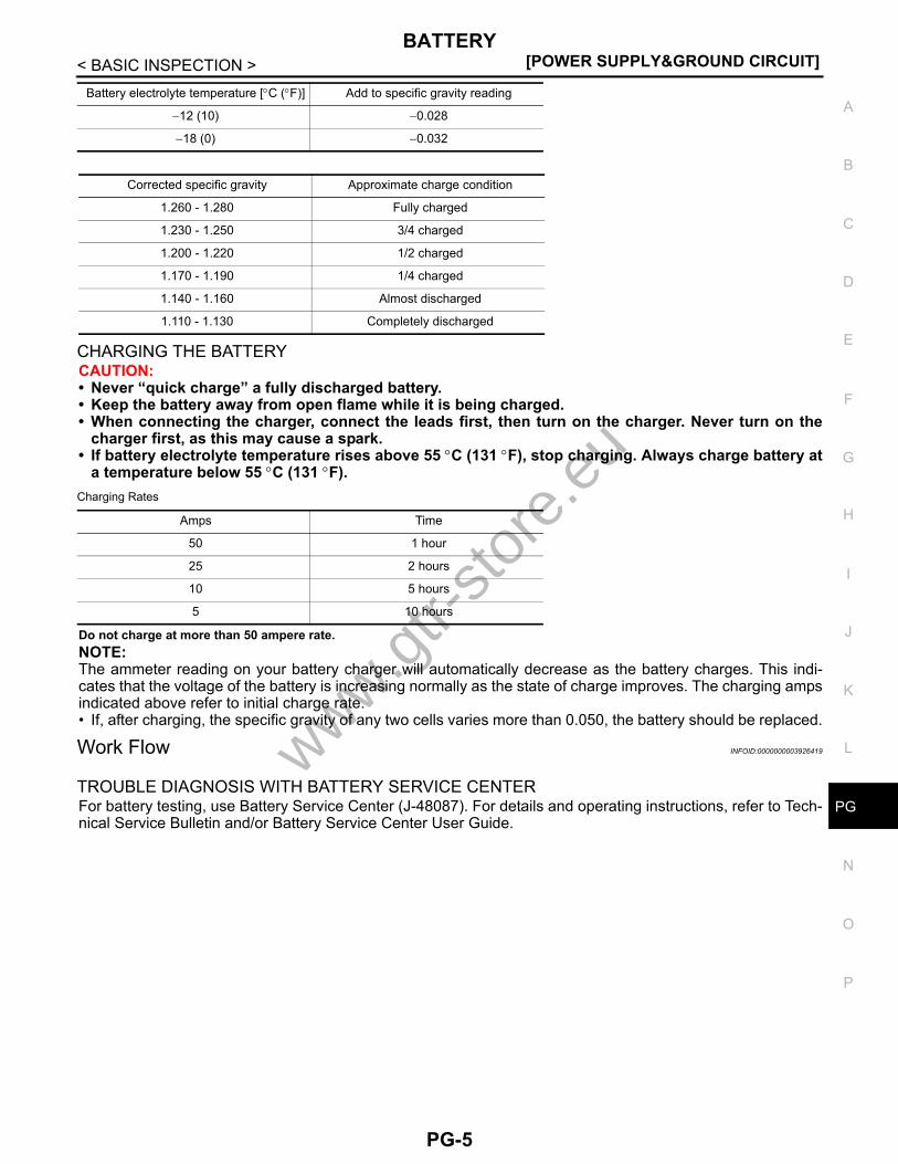
CHARGING THE BATTERYCAUTION:• Never “quick charge” a fully discharged battery.• Keep the battery away from open flame while it is being charged.• When connecting the charger, connect the leads first, then turn on the charger. Never turn on the
charger first, as this may cause a spark.• If battery electrolyte temperature rises above 55 °C (131 °F), stop charging. Always charge battery at
a temperature below 55 °C (131 °F).Charging Rates
Do not charge at more than 50 ampere rate.NOTE:The ammeter reading on your battery charger will automatically decrease as the battery charges. This indi-cates that the voltage of the battery is increasing normally as the state of charge improves. The charging ampsindicated above refer to initial charge rate.• If, after charging, the specific gravity of any two cells varies more than 0.050, the battery should be replaced.
Work Flow INFOID:0000000003926419
TROUBLE DIAGNOSIS WITH BATTERY SERVICE CENTERFor battery testing, use Battery Service Center (J-48087). For details and operating instructions, refer to Tech-nical Service Bulletin and/or Battery Service Center User Guide.
−12 (10) −0.028
−18 (0) −0.032
Battery electrolyte temperature [°C (°F)] Add to specific gravity reading
Corrected specific gravity Approximate charge condition
1.260 - 1.280 Fully charged
1.230 - 1.250 3/4 charged
1.200 - 1.220 1/2 charged
1.170 - 1.190 1/4 charged
1.140 - 1.160 Almost discharged
1.110 - 1.130 Completely discharged
Amps Time
50 1 hour
25 2 hours
10 5 hours
5 10 hours
www.gtr-
store
.eu
PG-5
[POWER SUPPLY&GROUND CIRCUIT]POWER SUPPLY ROUTING CIRCUIT
< COMPONENT DIAGNOSIS >
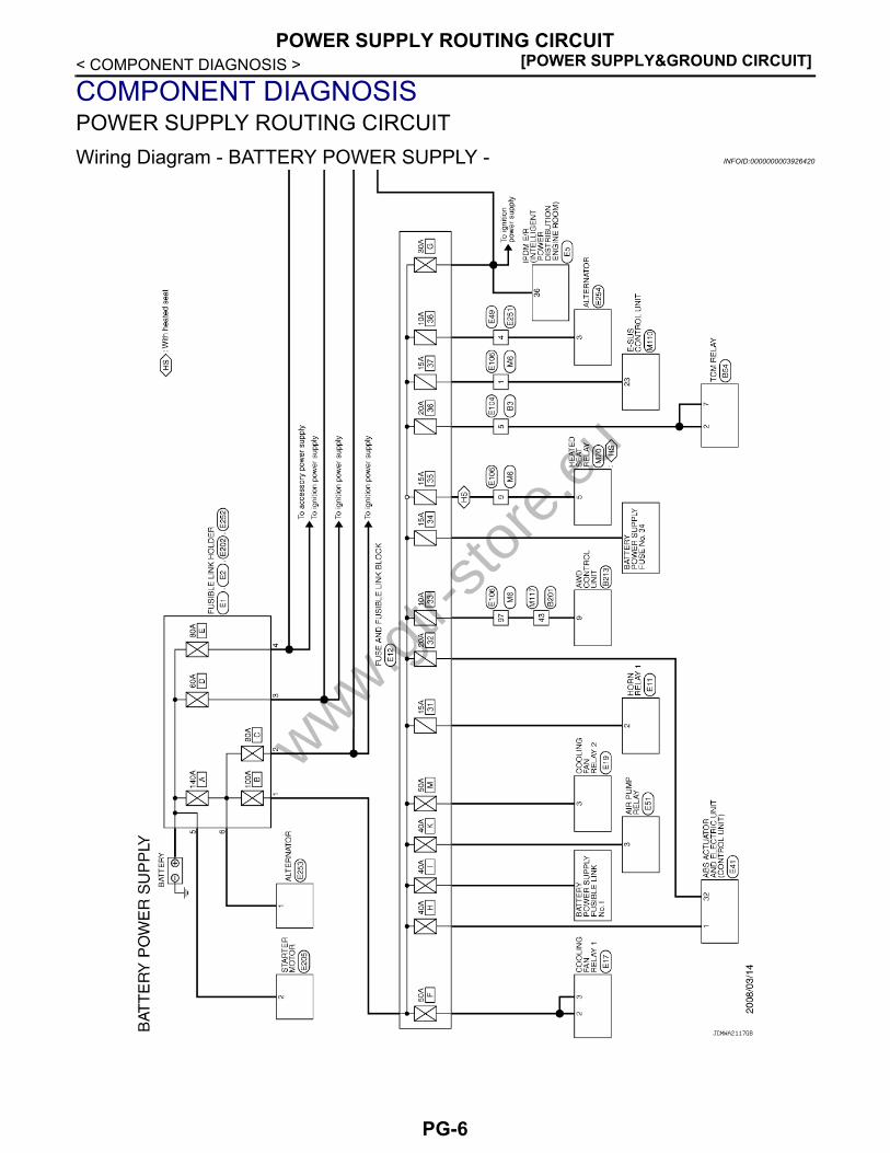
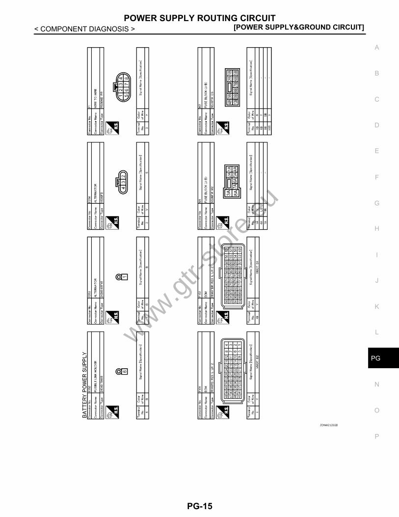
COMPONENT DIAGNOSISPOWER SUPPLY ROUTING CIRCUITWiring Diagram - BATTERY POWER SUPPLY - INFOID:0000000003926420
JCMWA2117GB
www.gtr-
store
.eu
PG-6

G
POWER SUPPLY ROUTING CIRCUIT[POWER SUPPLY&GROUND CIRCUIT]
C
D
E
F
G
H
I
J
K
L
B
A
O
P
N
P
< COMPONENT DIAGNOSIS >
JCMWA2118GB
www.gtr-
store
.eu
PG-7

[POWER SUPPLY&GROUND CIRCUIT]POWER SUPPLY ROUTING CIRCUIT
< COMPONENT DIAGNOSIS >
JCMWA2119GB
www.gtr-
store
.eu
PG-8

G
POWER SUPPLY ROUTING CIRCUIT[POWER SUPPLY&GROUND CIRCUIT]
C
D
E
F
G
H
I
J
K
L
B
A
O
P
N
P
< COMPONENT DIAGNOSIS >
JCMWA2120GB
www.gtr-
store
.eu
PG-9

[POWER SUPPLY&GROUND CIRCUIT]POWER SUPPLY ROUTING CIRCUIT
< COMPONENT DIAGNOSIS >
JCMWA2121GB
www.gtr-
store
.eu
PG-10

G
POWER SUPPLY ROUTING CIRCUIT[POWER SUPPLY&GROUND CIRCUIT]
C
D
E
F
G
H
I
J
K
L
B
A
O
P
N
P
< COMPONENT DIAGNOSIS >
JCMWA2122GB
www.gtr-
store
.eu
PG-11

[POWER SUPPLY&GROUND CIRCUIT]POWER SUPPLY ROUTING CIRCUIT
< COMPONENT DIAGNOSIS >
JCMWA2123GB
www.gtr-
store
.eu
PG-12

G
POWER SUPPLY ROUTING CIRCUIT[POWER SUPPLY&GROUND CIRCUIT]
C
D
E
F
G
H
I
J
K
L
B
A
O
P
N
P
< COMPONENT DIAGNOSIS >
JCMWA2124GB
www.gtr-
store
.eu
PG-13

[POWER SUPPLY&GROUND CIRCUIT]POWER SUPPLY ROUTING CIRCUIT
< COMPONENT DIAGNOSIS >
JCMWA2125GB
www.gtr-
store
.eu
PG-14
G
POWER SUPPLY ROUTING CIRCUIT[POWER SUPPLY&GROUND CIRCUIT]
C
D
E
F
G
H
I
J
K
L
B
A
O
P
N
P
< COMPONENT DIAGNOSIS >
JCMWA2126GB
www.gtr-
store
.eu
PG-15

[POWER SUPPLY&GROUND CIRCUIT]POWER SUPPLY ROUTING CIRCUIT
< COMPONENT DIAGNOSIS >
JCMWA2127GB
www.gtr-
store
.eu
PG-16

G
POWER SUPPLY ROUTING CIRCUIT[POWER SUPPLY&GROUND CIRCUIT]
C
D
E
F
G
H
I
J
K
L
B
A
O
P
N
P
< COMPONENT DIAGNOSIS >
JCMWA2128GB
www.gtr-
store
.eu
PG-17

[POWER SUPPLY&GROUND CIRCUIT]POWER SUPPLY ROUTING CIRCUIT
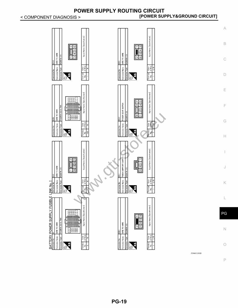
< COMPONENT DIAGNOSIS >Wiring Diagram - BATTERY POWER SUPPLY FUSIBLE LINK No. I - INFOID:0000000003926421
JCMWA2129GB
www.gtr-
store
.eu
PG-18
G
POWER SUPPLY ROUTING CIRCUIT[POWER SUPPLY&GROUND CIRCUIT]
C
D
E
F
G
H
I
J
K
L
B
A
O
P
N
P
< COMPONENT DIAGNOSIS >
JCMWA2130GB
www.gtr-
store
.eu
PG-19

[POWER SUPPLY&GROUND CIRCUIT]POWER SUPPLY ROUTING CIRCUIT
< COMPONENT DIAGNOSIS >
JCMWA2131GB
www.gtr-
store
.eu
PG-20

G
POWER SUPPLY ROUTING CIRCUIT[POWER SUPPLY&GROUND CIRCUIT]
C
D
E
F
G
H
I
J
K
L
B
A
O
P
N
P
< COMPONENT DIAGNOSIS >
JCMWA2132GB
www.gtr-
store
.eu
PG-21

[POWER SUPPLY&GROUND CIRCUIT]POWER SUPPLY ROUTING CIRCUIT
< COMPONENT DIAGNOSIS >Wiring Diagram - BATTERY POWER SUPPLY FUSE No. 6 - INFOID:0000000003926422
JCMWA2133GB
www.gtr-
store
.eu
PG-22

G
POWER SUPPLY ROUTING CIRCUIT[POWER SUPPLY&GROUND CIRCUIT]
C
D
E
F
G
H
I
J
K
L
B
A
O
P
N
P
< COMPONENT DIAGNOSIS >
JCMWA2134GB
www.gtr-
store
.eu
PG-23

[POWER SUPPLY&GROUND CIRCUIT]POWER SUPPLY ROUTING CIRCUIT
< COMPONENT DIAGNOSIS >
JCMWA2135GB
www.gtr-
store
.eu
PG-24

G
POWER SUPPLY ROUTING CIRCUIT[POWER SUPPLY&GROUND CIRCUIT]
C
D
E
F
G
H
I
J
K
L
B
A
O
P
N
P
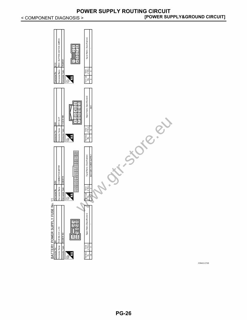
< COMPONENT DIAGNOSIS >Wiring Diagram - BATTERY POWER SUPPLY FUSE No. 11 - INFOID:0000000003926423
JCMWA2136GB
www.gtr-
store
.eu
PG-25
[POWER SUPPLY&GROUND CIRCUIT]POWER SUPPLY ROUTING CIRCUIT
< COMPONENT DIAGNOSIS >
JCMWA2137GB
www.gtr-
store
.eu
PG-26

G
POWER SUPPLY ROUTING CIRCUIT[POWER SUPPLY&GROUND CIRCUIT]
C
D
E
F
G
H
I
J
K
L
B
A
O
P
N
P
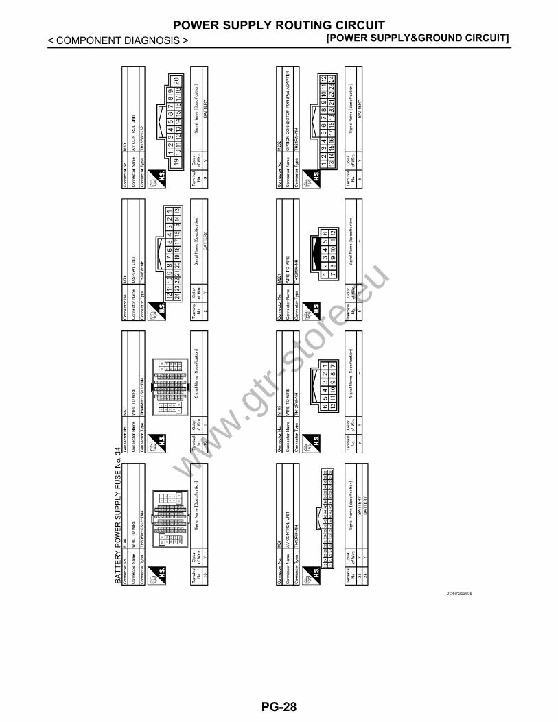
< COMPONENT DIAGNOSIS >Wiring Diagram - BATTERY POWER SUPPLY FUSE No. 34 - INFOID:0000000003926426
JCMWA2138GB
www.gtr-
store
.eu
PG-27
[POWER SUPPLY&GROUND CIRCUIT]POWER SUPPLY ROUTING CIRCUIT
< COMPONENT DIAGNOSIS >
JCMWA2139GB
www.gtr-
store
.eu
PG-28

G
POWER SUPPLY ROUTING CIRCUIT[POWER SUPPLY&GROUND CIRCUIT]
C
D
E
F
G
H
I
J
K
L
B
A
O
P
N
P
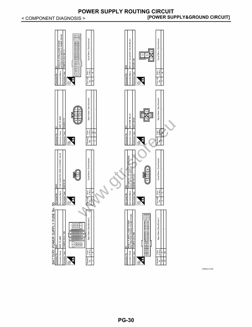
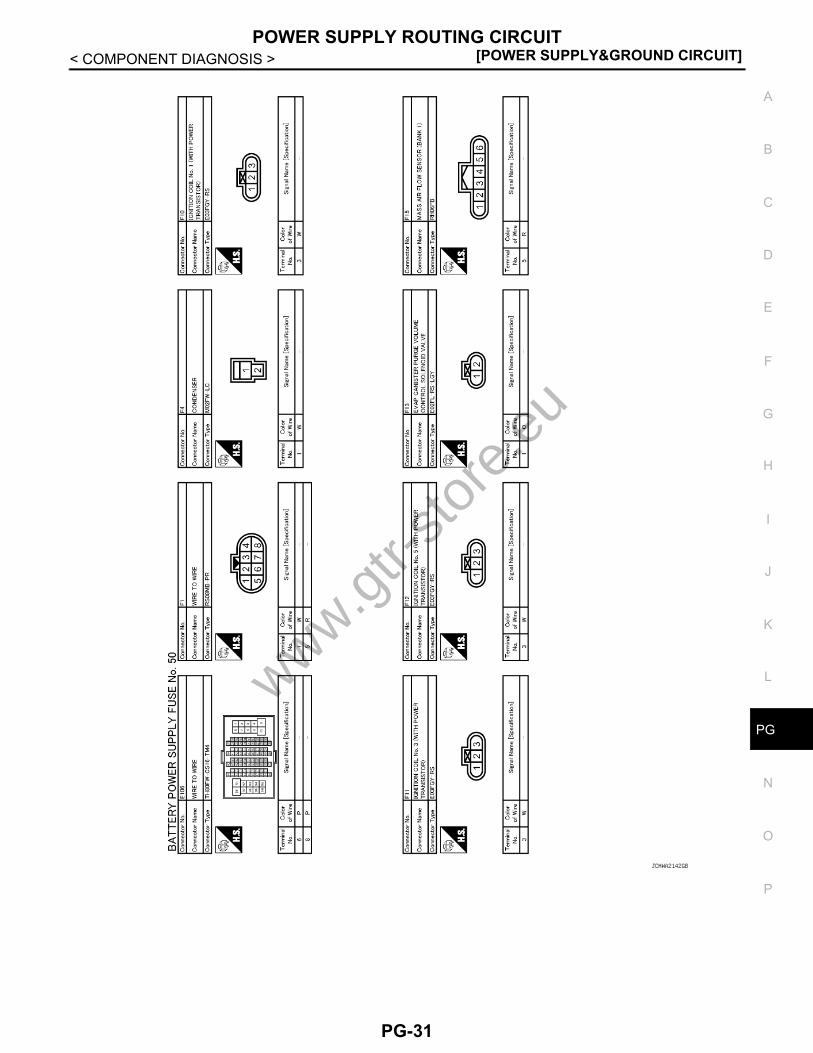
< COMPONENT DIAGNOSIS >Wiring Diagram - BATTERY POWER SUPPLY FUSE No. 50 - INFOID:0000000003926427
JCMWA2140GB
www.gtr-
store
.eu
PG-29
[POWER SUPPLY&GROUND CIRCUIT]POWER SUPPLY ROUTING CIRCUIT
< COMPONENT DIAGNOSIS >
JCMWA2141GB
www.gtr-
store
.eu
PG-30
G
POWER SUPPLY ROUTING CIRCUIT[POWER SUPPLY&GROUND CIRCUIT]
C
D
E
F
G
H
I
J
K
L
B
A
O
P
N
P
< COMPONENT DIAGNOSIS >
JCMWA2142GB
www.gtr-
store
.eu
PG-31
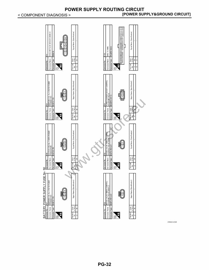
[POWER SUPPLY&GROUND CIRCUIT]POWER SUPPLY ROUTING CIRCUIT
< COMPONENT DIAGNOSIS >
JCMWA2143GB
www.gtr-
store
.eu
PG-32

G
POWER SUPPLY ROUTING CIRCUIT[POWER SUPPLY&GROUND CIRCUIT]
C
D
E
F
G
H
I
J
K
L
B
A
O
P
N
P
< COMPONENT DIAGNOSIS >
JCMWA2144GB
www.gtr-
store
.eu
PG-33

[POWER SUPPLY&GROUND CIRCUIT]POWER SUPPLY ROUTING CIRCUIT
< COMPONENT DIAGNOSIS >Wiring Diagram - BATTERY POWER SUPPLY FUSE No. 53 - INFOID:0000000003926428
JCMWA2145GB
www.gtr-
store
.eu
PG-34

G
POWER SUPPLY ROUTING CIRCUIT[POWER SUPPLY&GROUND CIRCUIT]
C
D
E
F
G
H
I
J
K
L
B
A
O
P
N
P
< COMPONENT DIAGNOSIS >
JCMWA2146GB
www.gtr-
store
.eu
PG-35

[POWER SUPPLY&GROUND CIRCUIT]POWER SUPPLY ROUTING CIRCUIT
< COMPONENT DIAGNOSIS >
JCMWA2147GB
www.gtr-
store
.eu
PG-36

G
POWER SUPPLY ROUTING CIRCUIT[POWER SUPPLY&GROUND CIRCUIT]
C
D
E
F
G
H
I
J
K
L
B
A
O
P
N
P
< COMPONENT DIAGNOSIS >
JCMWA2148GB
www.gtr-
store
.eu
PG-37
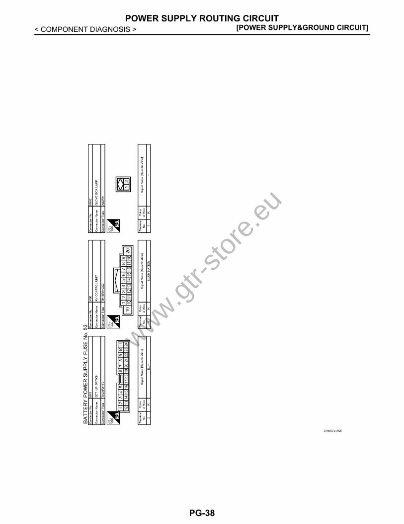
[POWER SUPPLY&GROUND CIRCUIT]POWER SUPPLY ROUTING CIRCUIT
< COMPONENT DIAGNOSIS >
JCMWA2149GB
www.gtr-
store
.eu
PG-38
G
POWER SUPPLY ROUTING CIRCUIT[POWER SUPPLY&GROUND CIRCUIT]
C
D
E
F
G
H
I
J
K
L
B
A
O
P
N
P
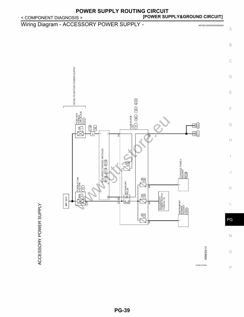
< COMPONENT DIAGNOSIS >Wiring Diagram - ACCESSORY POWER SUPPLY - INFOID:0000000003926429
JCMWA2150GB
www.gtr-
store
.eu
PG-39

[POWER SUPPLY&GROUND CIRCUIT]POWER SUPPLY ROUTING CIRCUIT
< COMPONENT DIAGNOSIS >
JCMWA2151GB
www.gtr-
store
.eu
PG-40
G
POWER SUPPLY ROUTING CIRCUIT[POWER SUPPLY&GROUND CIRCUIT]
C
D
E
F
G
H
I
J
K
L
B
A
O
P
N
P
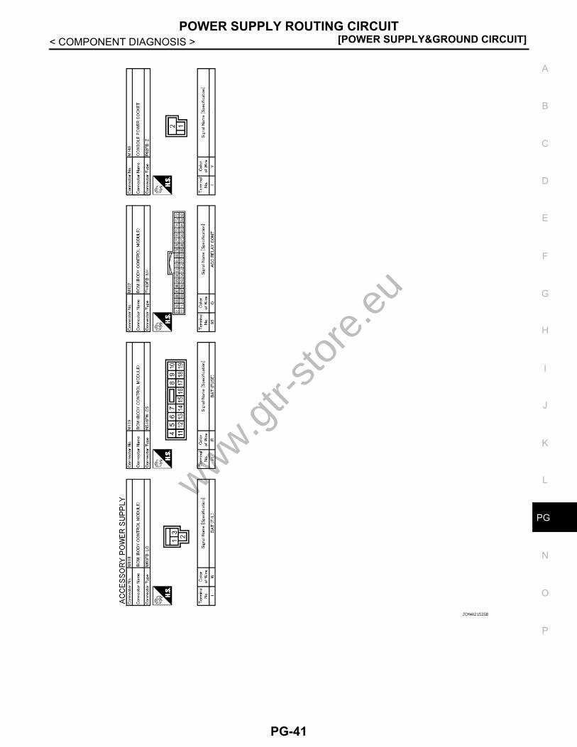
< COMPONENT DIAGNOSIS >
JCMWA2152GB
www.gtr-
store
.eu
PG-41

[POWER SUPPLY&GROUND CIRCUIT]POWER SUPPLY ROUTING CIRCUIT
< COMPONENT DIAGNOSIS >Wiring Diagram - ACCESSORY POWER SUPPLY FUSE No. 19 - INFOID:0000000003926430
JCMWA2153GB
www.gtr-
store
.eu
PG-42

G
POWER SUPPLY ROUTING CIRCUIT[POWER SUPPLY&GROUND CIRCUIT]
C
D
E
F
G
H
I
J
K
L
B
A
O
P
N
P
< COMPONENT DIAGNOSIS >
JCMWA2154GB
www.gtr-
store
.eu
PG-43

[POWER SUPPLY&GROUND CIRCUIT]POWER SUPPLY ROUTING CIRCUIT
< COMPONENT DIAGNOSIS >
JCMWA2155GB
www.gtr-
store
.eu
PG-44

G
POWER SUPPLY ROUTING CIRCUIT[POWER SUPPLY&GROUND CIRCUIT]
C
D
E
F
G
H
I
J
K
L
B
A
O
P
N
P
< COMPONENT DIAGNOSIS >Wiring Diagram - IGNITION POWER SUPPLY - INFOID:0000000003926431
JCMWA2156GB
www.gtr-
store
.eu
PG-45
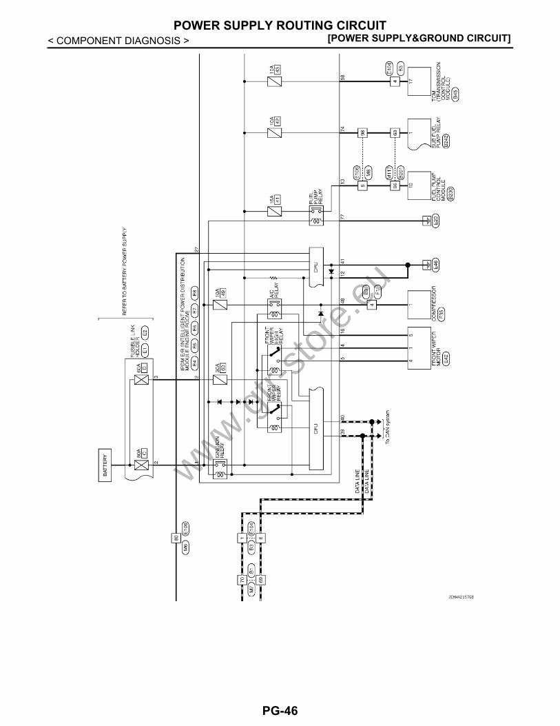
[POWER SUPPLY&GROUND CIRCUIT]POWER SUPPLY ROUTING CIRCUIT
< COMPONENT DIAGNOSIS >
JCMWA2157GB
www.gtr-
store
.eu
PG-46

G
POWER SUPPLY ROUTING CIRCUIT[POWER SUPPLY&GROUND CIRCUIT]
C
D
E
F
G
H
I
J
K
L
B
A
O
P
N
P
< COMPONENT DIAGNOSIS >
JCMWA2158GB
www.gtr-
store
.eu
PG-47
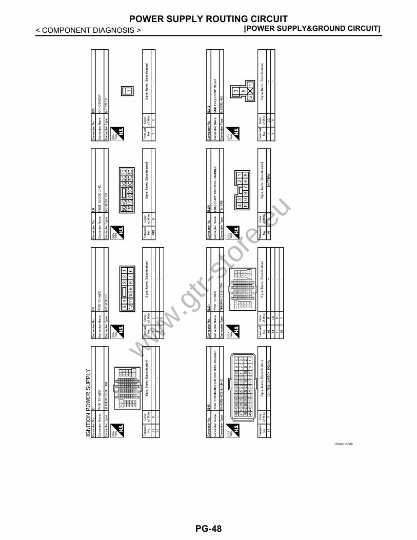
[POWER SUPPLY&GROUND CIRCUIT]POWER SUPPLY ROUTING CIRCUIT
< COMPONENT DIAGNOSIS >
JCMWA2159GB
www.gtr-
store
.eu
PG-48

G
POWER SUPPLY ROUTING CIRCUIT[POWER SUPPLY&GROUND CIRCUIT]
C
D
E
F
G
H
I
J
K
L
B
A
O
P
N
P
< COMPONENT DIAGNOSIS >
JCMWA2160GB
www.gtr-
store
.eu
PG-49

[POWER SUPPLY&GROUND CIRCUIT]POWER SUPPLY ROUTING CIRCUIT
< COMPONENT DIAGNOSIS >
JCMWA2161GB
www.gtr-
store
.eu
PG-50
G
POWER SUPPLY ROUTING CIRCUIT[POWER SUPPLY&GROUND CIRCUIT]
C
D
E
F
G
H
I
J
K
L
B
A
O
P
N
P
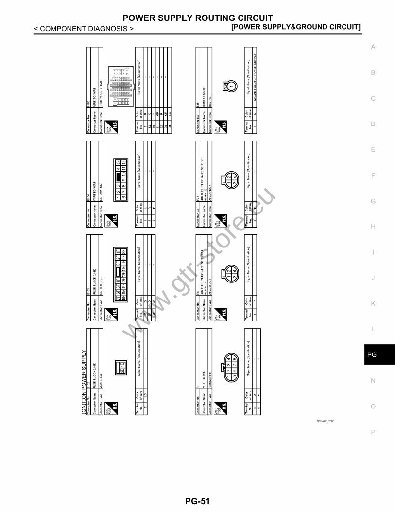
< COMPONENT DIAGNOSIS >
JCMWA2162GB
www.gtr-
store
.eu
PG-51

[POWER SUPPLY&GROUND CIRCUIT]POWER SUPPLY ROUTING CIRCUIT
< COMPONENT DIAGNOSIS >
JCMWA2163GB
www.gtr-
store
.eu
PG-52

G
POWER SUPPLY ROUTING CIRCUIT[POWER SUPPLY&GROUND CIRCUIT]
C
D
E
F
G
H
I
J
K
L
B
A
O
P
N
P
< COMPONENT DIAGNOSIS >
JCMWA2164GB
www.gtr-
store
.eu
PG-53

[POWER SUPPLY&GROUND CIRCUIT]POWER SUPPLY ROUTING CIRCUIT
< COMPONENT DIAGNOSIS >
JCMWA2165GB
www.gtr-
store
.eu
PG-54

G
POWER SUPPLY ROUTING CIRCUIT[POWER SUPPLY&GROUND CIRCUIT]
C
D
E
F
G
H
I
J
K
L
B
A
O
P
N
P
< COMPONENT DIAGNOSIS >Wiring Diagram - IGNITION POWER SUPPLY FUSE No. 3 - INFOID:0000000003926432
JCMWA2166GB
www.gtr-
store
.eu
PG-55

[POWER SUPPLY&GROUND CIRCUIT]POWER SUPPLY ROUTING CIRCUIT
< COMPONENT DIAGNOSIS >
JCMWA2167GB
www.gtr-
store
.eu
PG-56

G
POWER SUPPLY ROUTING CIRCUIT[POWER SUPPLY&GROUND CIRCUIT]
C
D
E
F
G
H
I
J
K
L
B
A
O
P
N
P
< COMPONENT DIAGNOSIS >
JCMWA2168GB
www.gtr-
store
.eu
PG-57

[POWER SUPPLY&GROUND CIRCUIT]POWER SUPPLY ROUTING CIRCUIT
< COMPONENT DIAGNOSIS >Wiring Diagram - IGNITION POWER SUPPLY FUSE No. 4 - INFOID:0000000003926433
JCMWA2169GB
www.gtr-
store
.eu
PG-58

G
POWER SUPPLY ROUTING CIRCUIT[POWER SUPPLY&GROUND CIRCUIT]
C
D
E
F
G
H
I
J
K
L
B
A
O
P
N
P
< COMPONENT DIAGNOSIS >
JCMWA2170GB
www.gtr-
store
.eu
PG-59

[POWER SUPPLY&GROUND CIRCUIT]POWER SUPPLY ROUTING CIRCUIT
< COMPONENT DIAGNOSIS >Wiring Diagram - IGNITION POWER SUPPLY FUSE No. 44 - INFOID:0000000003926434
JCMWA2171GB
www.gtr-
store
.eu
PG-60

G
POWER SUPPLY ROUTING CIRCUIT[POWER SUPPLY&GROUND CIRCUIT]
C
D
E
F
G
H
I
J
K
L
B
A
O
P
N
P
< COMPONENT DIAGNOSIS >
JCMWA2172GB
www.gtr-
store
.eu
PG-61

[POWER SUPPLY&GROUND CIRCUIT]POWER SUPPLY ROUTING CIRCUIT
< COMPONENT DIAGNOSIS >
JCMWA2173GB
www.gtr-
store
.eu
PG-62
G
POWER SUPPLY ROUTING CIRCUIT[POWER SUPPLY&GROUND CIRCUIT]
C
D
E
F
G
H
I
J
K
L
B
A
O
P
N
P
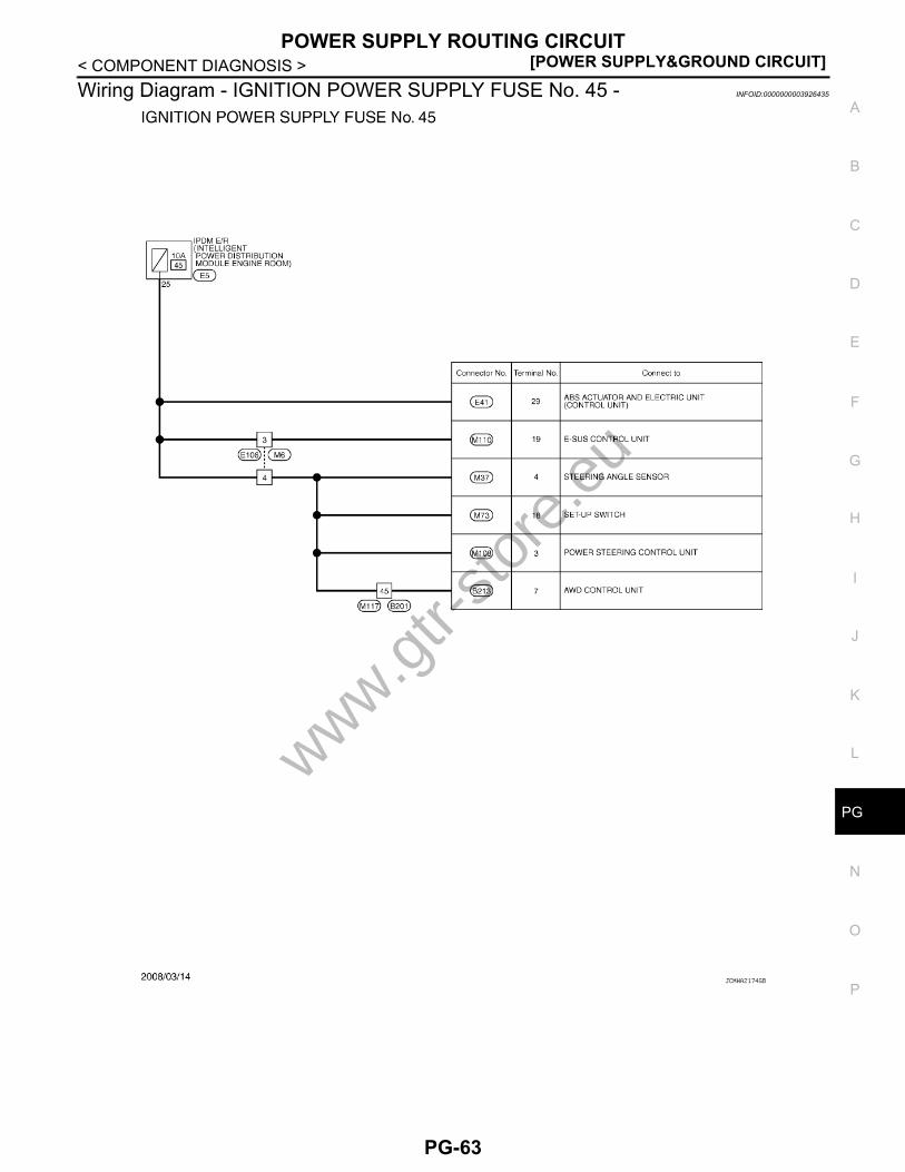
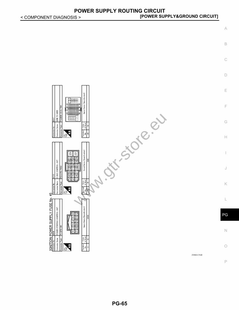
< COMPONENT DIAGNOSIS >Wiring Diagram - IGNITION POWER SUPPLY FUSE No. 45 - INFOID:0000000003926435
JCMWA2174GB
www.gtr-
store
.eu
PG-63

[POWER SUPPLY&GROUND CIRCUIT]POWER SUPPLY ROUTING CIRCUIT
< COMPONENT DIAGNOSIS >
JCMWA2175GB
www.gtr-
store
.eu
PG-64
G
POWER SUPPLY ROUTING CIRCUIT[POWER SUPPLY&GROUND CIRCUIT]
C
D
E
F
G
H
I
J
K
L
B
A
O
P
N
P
< COMPONENT DIAGNOSIS >
JCMWA2176GB
www.gtr-
store
.eu
PG-65

[POWER SUPPLY&GROUND CIRCUIT]POWER SUPPLY ROUTING CIRCUIT
< COMPONENT DIAGNOSIS >Fuse INFOID:0000000003926436
• If fuse is blown, be sure to eliminate cause of malfunction beforeinstalling new fuse.
• Use fuse of specified rating. Never use fuse of more than specifiedrating.
• Do not partially install fuse; always insert it into fuse holder prop-erly.
• Remove fuse for “ELECTRICAL PARTS (BAT)” if vehicle is notused for a long period of time.
Fusible Link INFOID:0000000003926437
A melted fusible link can be detected either by visual inspection or byfeeling with finger tip. If its condition is questionable, use circuittester or test lamp.
CAUTION:• If fusible link should melt, it is possible that critical circuit
(power supply or large current carrying circuit) is shorted. Insuch a case, carefully check and eliminate cause of malfunc-tion.
• Never wrap outside of fusible link with vinyl tape. Important:Never let fusible link touch any other wiring harness, vinyl orrubber parts.
Circuit Breaker INFOID:0000000003926438
The PTC thermistor generates heat in response to current flow. Thetemperature (and resistance) of the thermistor element varies withcurrent flow. Excessive current flow will cause the element's temper-ature to rise. When the temperature reaches a specified level, theelectrical resistance will rise sharply to control the circuit current.Reduced current flow will cause the element to cool. Resistance fallsaccordingly and normal circuit current flow is allowed to resume.
CEL083
1 : Fusible link
JPMIA1074ZZ
SEL109W
www.gtr-
store
.eu
PG-66

G
HARNESS LAYOUT[POWER SUPPLY&GROUND CIRCUIT]
C
D
E
F
G
H
I
J
K
L
B
A
O
P
N
P
< COMPONENT DIAGNOSIS >HARNESS LAYOUTHow To Read Harness Layout INFOID:0000000003926439
CONNECTOR SYMBOLMain symbols of connector (in Harness Layout) are indicated in the below.
1 : Connector model2 : Cavity3 : Male (M) and female (F) terminals4 : Connector color5 : Special type
JPMIA0113GB
JPMIA0114GB
www.gtr-
store
.eu
PG-67

[POWER SUPPLY&GROUND CIRCUIT]HARNESS LAYOUT
< COMPONENT DIAGNOSIS >Outline INFOID:0000000003926440
JCMIA0325GB
www.gtr-
store
.eu
PG-68
G
HARNESS LAYOUT[POWER SUPPLY&GROUND CIRCUIT]
C
D
E
F
G
H
I
J
K
L
B
A
O
P
N
P
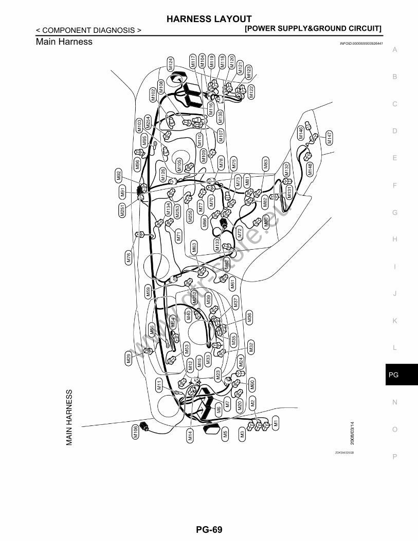
< COMPONENT DIAGNOSIS >Main Harness INFOID:0000000003926441
JCMIA0326GB
www.gtr-
store
.eu
PG-69

[POWER SUPPLY&GROUND CIRCUIT]HARNESS LAYOUT
< COMPONENT DIAGNOSIS >Engine Room Harness INFOID:0000000003926442
ENGINE COMPARTMENT
JCMIA0327GB
www.gtr-
store
.eu
PG-70

G
HARNESS LAYOUT[POWER SUPPLY&GROUND CIRCUIT]
C
D
E
F
G
H
I
J
K
L
B
A
O
P
N
P
< COMPONENT DIAGNOSIS >PASSENGER COMPARTMENT
JCMIA0328GB
www.gtr-
store
.eu
PG-71

[POWER SUPPLY&GROUND CIRCUIT]HARNESS LAYOUT
< COMPONENT DIAGNOSIS >Engine Control Harness INFOID:0000000003926443
ENGINE COMPARTMENT
JCMIA0329GB
www.gtr-
store
.eu
PG-72

G
HARNESS LAYOUT[POWER SUPPLY&GROUND CIRCUIT]
C
D
E
F
G
H
I
J
K
L
B
A
O
P
N
P
< COMPONENT DIAGNOSIS >PASSENGER COMPARTMENT
JCMIA0330GB
www.gtr-
store
.eu
PG-73

[POWER SUPPLY&GROUND CIRCUIT]HARNESS LAYOUT
< COMPONENT DIAGNOSIS >Body Harness INFOID:0000000003926444
JCMIA0331GB
www.gtr-
store
.eu
PG-74
G
HARNESS LAYOUT[POWER SUPPLY&GROUND CIRCUIT]
C
D
E
F
G
H
I
J
K
L
B
A
O
P
N
P
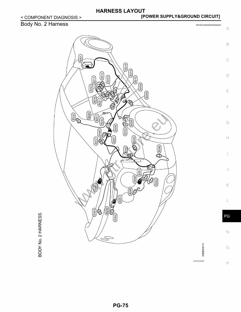
< COMPONENT DIAGNOSIS >Body No. 2 Harness INFOID:0000000003926445
JCMIA0332GB
www.gtr-
store
.eu
PG-75

[POWER SUPPLY&GROUND CIRCUIT]HARNESS LAYOUT
< COMPONENT DIAGNOSIS >Room Lamp Harness INFOID:0000000003926446
JCMIA0333GB
www.gtr-
store
.eu
PG-76

G
HARNESS LAYOUT[POWER SUPPLY&GROUND CIRCUIT]
C
D
E
F
G
H
I
J
K
L
B
A
O
P
N
P
< COMPONENT DIAGNOSIS >Door Harness (Driver Side Door) INFOID:0000000003926465
JCMIA0334GB
www.gtr-
store
.eu
PG-77

[POWER SUPPLY&GROUND CIRCUIT]HARNESS LAYOUT
< COMPONENT DIAGNOSIS >Door Harness (Passenger Side Door) INFOID:0000000003926466
JCMIA0335GB
www.gtr-
store
.eu
PG-78

G
HARNESS CONNECTOR[POWER SUPPLY&GROUND CIRCUIT]
C
D
E
F
G
H
I
J
K
L
B
A
O
P
N
P
< COMPONENT DIAGNOSIS >HARNESS CONNECTORDescription INFOID:0000000003926452
HARNESS CONNECTOR (TAB-LOCKING TYPE)• The tab-locking type connectors help prevent accidental looseness or disconnection.• The tab-locking type connectors are disconnected by pushing or lifting the locking tab(s). Refer to the figure
below.CAUTION:Never pull the harness or wires when disconnecting the connector.
[Example]
HARNESS CONNECTOR (SLIDE-LOCKING TYPE)• A new style slide-locking type connector is used on certain systems and components, especially those
related to OBD.• The slide-locking type connectors help prevent incomplete locking and accidental looseness or disconnec-
tion.• The slide-locking type connectors are disconnected by pushing or pulling the slider. Refer to the figure
below.
SEL769DA
www.gtr-
store
.eu
PG-79

[POWER SUPPLY&GROUND CIRCUIT]HARNESS CONNECTOR
< COMPONENT DIAGNOSIS >CAUTION:• Never pull the harness or wires when disconnecting the connector.• Be careful not to damage the connector support bracket when disconnecting the connector.
[Example]
HARNESS CONNECTOR (LEVER LOCKING TYPE)• Lever locking type harness connectors are used on certain control units and control modules such as ECM,
ABS actuator and electric unit (control unit), etc.• Lever locking type harness connectors are also used on super multiple junction (SMJ) connectors.• Always confirm the lever is fully locked in place by moving the lever as far as it will go to ensure full connec-
tion.CAUTION:
SEL769V
www.gtr-
store
.eu
PG-80

G
HARNESS CONNECTOR[POWER SUPPLY&GROUND CIRCUIT]
C
D
E
F
G
H
I
J
K
L
B
A
O
P
N
P
< COMPONENT DIAGNOSIS >Always confirm the lever is fully released (loosened) before attempting to disconnect or connect theseconnectors to avoid damage to the connector housing or terminals.
LKIA0670E
1. Control unit with single leverA. FastenB. LoosenC. Lever
2. Control unit with dual leversA. LeversB. FastenC. Loosen
3. SMJ connectorA. LeverB. FastenC. Loosen
www.gtr-
store
.eu
PG-81
[POWER SUPPLY&GROUND CIRCUIT]STANDARDIZED RELAY
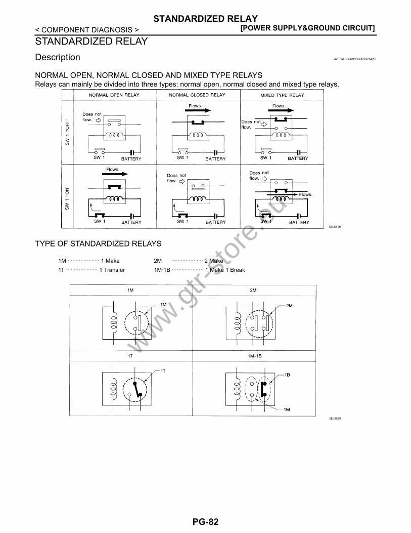
< COMPONENT DIAGNOSIS >STANDARDIZED RELAYDescription INFOID:0000000003926453
NORMAL OPEN, NORMAL CLOSED AND MIXED TYPE RELAYSRelays can mainly be divided into three types: normal open, normal closed and mixed type relays.
TYPE OF STANDARDIZED RELAYS
SEL881H
1M ···················· 1 Make 2M ···················· 2 Make1T ···················· 1 Transfer 1M·1B ···················· 1 Make 1 Break
SEL882H
www.gtr-
store
.eu
PG-82

G
STANDARDIZED RELAY[POWER SUPPLY&GROUND CIRCUIT]
C
D
E
F
G
H
I
J
K
L
B
A
O
P
N
P
< COMPONENT DIAGNOSIS >
SEL188W
www.gtr-
store
.eu
PG-83

[POWER SUPPLY&GROUND CIRCUIT]FUSE BLOCK - JUNCTION BOX (J/B)
< COMPONENT DIAGNOSIS >FUSE BLOCK - JUNCTION BOX (J/B)Fuse, Connector and Terminal Arrangement INFOID:0000000003926454
JCMWA2177GB
www.gtr-
store
.eu
PG-84
G
FUSE, FUSIBLE LINK AND RELAY BOX[POWER SUPPLY&GROUND CIRCUIT]
C
D
E
F
G
H
I
J
K
L
B
A
O
P
N
P
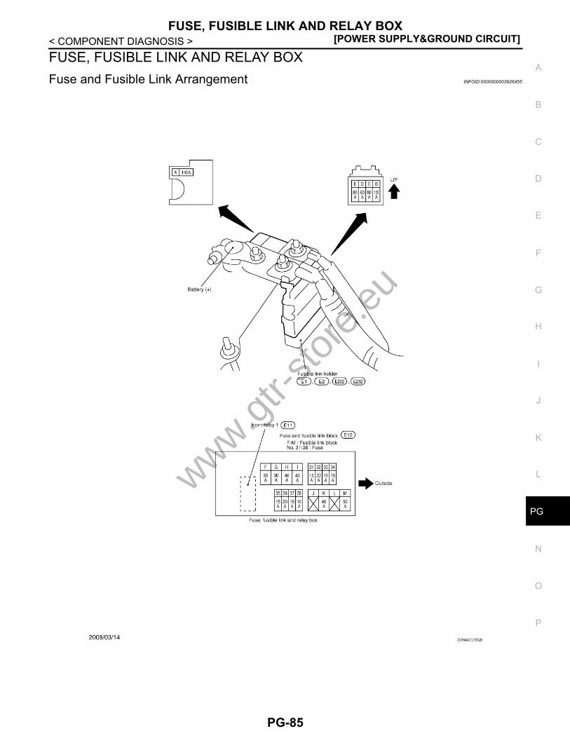
< COMPONENT DIAGNOSIS >FUSE, FUSIBLE LINK AND RELAY BOXFuse and Fusible Link Arrangement INFOID:0000000003926455
JCMWA2178GB
www.gtr-
store
.eu
PG-85

[POWER SUPPLY&GROUND CIRCUIT]IPDM E/R (INTELLIGENT POWER DISTRIBUTION MODULE ENGINE ROOM)
< COMPONENT DIAGNOSIS >IPDM E/R (INTELLIGENT POWER DISTRIBUTION MODULE ENGINEROOM)Fuse, Connector and Terminal Arrangement INFOID:0000000003926456
JCMWA2179GB
www.gtr-
store
.eu
PG-86
G
PRECAUTIONS[POWER SUPPLY&GROUND CIRCUIT]
C
D
E
F
G
H
I
J
K
L
B
A
O
P
N
P
< PRECAUTION >
PRECAUTIONPRECAUTIONSPrecaution for Supplemental Restraint System (SRS) "AIR BAG" and "SEAT BELT PRE-TENSIONER" INFOID:0000000004114425
The Supplemental Restraint System such as “AIR BAG” and “SEAT BELT PRE-TENSIONER”, used alongwith a front seat belt, helps to reduce the risk or severity of injury to the driver and front passenger for certaintypes of collision. This system includes seat belt switch inputs and dual stage front air bag modules. The SRSsystem uses the seat belt switches to determine the front air bag deployment, and may only deploy one frontair bag, depending on the severity of a collision and whether the front occupants are belted or unbelted.Information necessary to service the system safely is included in the “SRS AIRBAG” and “SEAT BELT” of thisService Manual.WARNING:• To avoid rendering the SRS inoperative, which could increase the risk of personal injury or death in
the event of a collision which would result in air bag inflation, all maintenance must be performed byan authorized NISSAN/INFINITI dealer.
• Improper maintenance, including incorrect removal and installation of the SRS, can lead to personalinjury caused by unintentional activation of the system. For removal of Spiral Cable and Air BagModule, see the “SRS AIRBAG”.
• Never use electrical test equipment on any circuit related to the SRS unless instructed to in this Ser-vice Manual. SRS wiring harnesses can be identified by yellow and/or orange harnesses or harnessconnectors.
Precaution for Battery Service INFOID:0000000004114426
Before disconnecting the battery, lower both the driver and passenger windows. This will prevent any interfer-ence between the window edge and the vehicle when the door is opened/closed. During normal operation, thewindow slightly raises and lowers automatically to prevent any window to vehicle interference. The automaticwindow function will not work with the battery disconnected.
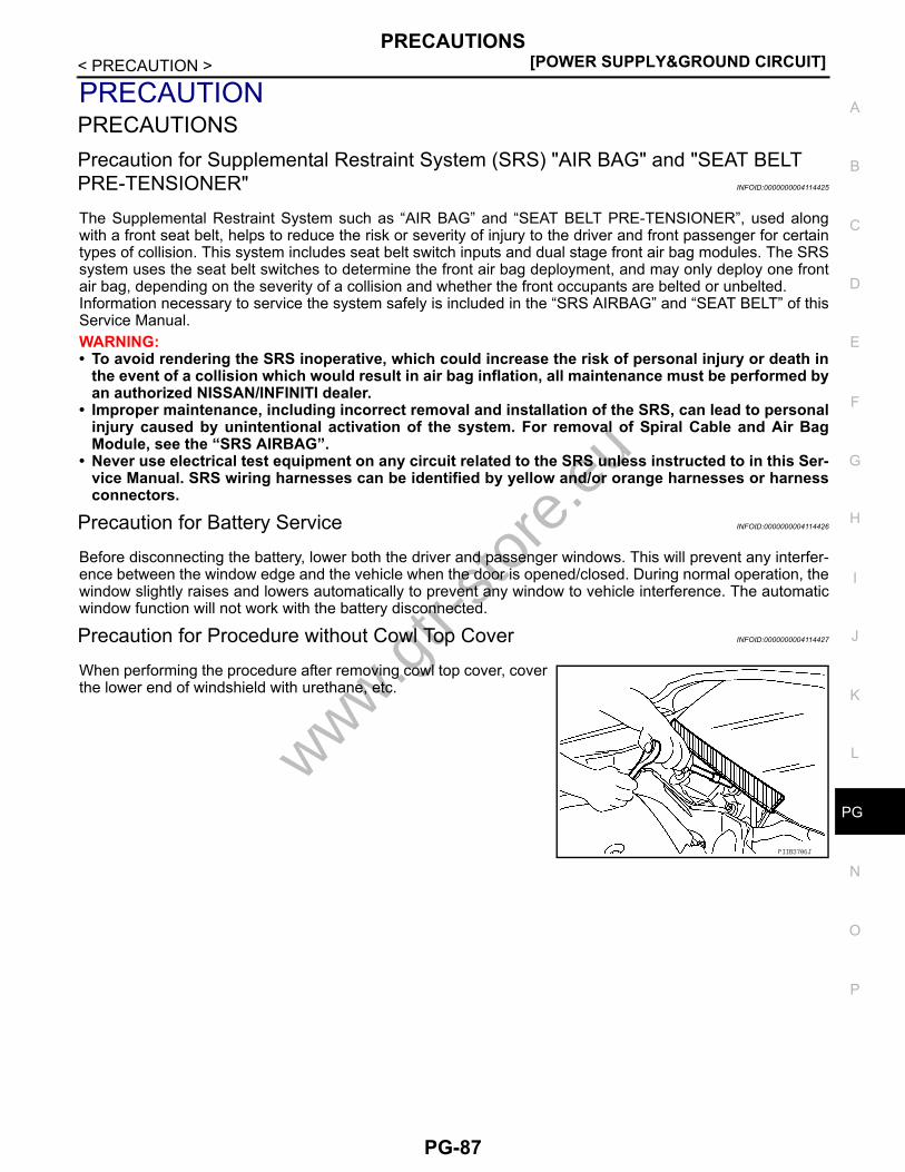
Precaution for Procedure without Cowl Top Cover INFOID:0000000004114427
When performing the procedure after removing cowl top cover, coverthe lower end of windshield with urethane, etc.
PIIB3706J
www.gtr-
store
.eu
PG-87

[POWER SUPPLY&GROUND CIRCUIT]PREPARATION
< PREPARATION >
PREPARATIONPREPARATIONSpecial Service Tools INFOID:0000000003926459
Tool number(Kent-Moore No.)Tool name
Description
—(J-48087)Battery Service Center Tests battery.
For operating instructions, refer to Technical Service Bulletin and Battery Service Center User Guide.
WKIA5280E
www.gtr-
store
.eu
PG-88
G
BATTERY[POWER SUPPLY&GROUND CIRCUIT]
C
D
E
F
G
H
I
J
K
L
B
A
O
P
N
P
< ON-VEHICLE REPAIR >
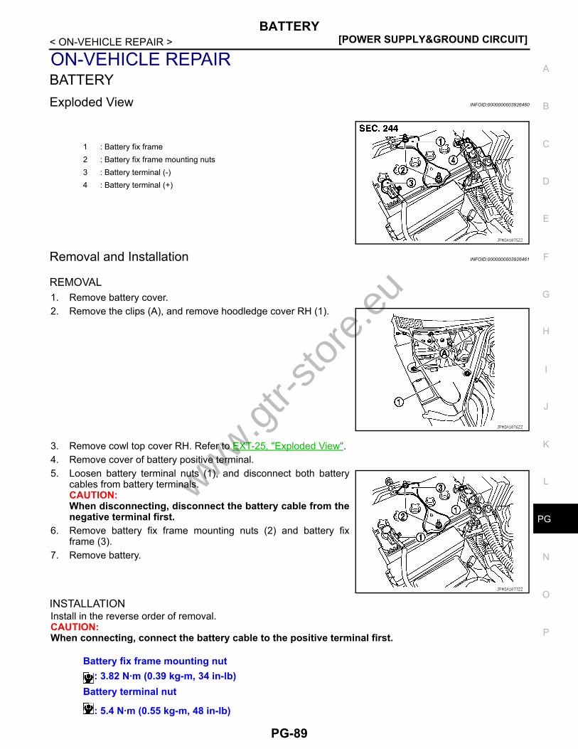
ON-VEHICLE REPAIRBATTERYExploded View INFOID:0000000003926460
Removal and Installation INFOID:0000000003926461
REMOVAL1. Remove battery cover.2. Remove the clips (A), and remove hoodledge cover RH (1).
3. Remove cowl top cover RH. Refer to EXT-25, "Exploded View".4. Remove cover of battery positive terminal.5. Loosen battery terminal nuts (1), and disconnect both battery
cables from battery terminals. CAUTION:When disconnecting, disconnect the battery cable from thenegative terminal first.
6. Remove battery fix frame mounting nuts (2) and battery fixframe (3).
7. Remove battery.
INSTALLATIONInstall in the reverse order of removal.CAUTION:When connecting, connect the battery cable to the positive terminal first.
1 : Battery fix frame2 : Battery fix frame mounting nuts3 : Battery terminal (-)4 : Battery terminal (+)
JPMIA1075ZZ
JPMIA1076ZZ
JPMIA1077ZZ
Battery fix frame mounting nut: 3.82 N·m (0.39 kg-m, 34 in-lb)
Battery terminal nut
: 5.4 N·m (0.55 kg-m, 48 in-lb)
www.gtr-
store
.eu
PG-89

[POWER SUPPLY&GROUND CIRCUIT]BATTERY
< ON-VEHICLE REPAIR >Reset electronic systems as necessary. Refer to GI-51, "ADDITIONAL SERVICE WHEN REMOVING BAT-TERY NEGATIVE TERMINAL : Required Procedure After Battery Disconnection".
www.gtr-
store
.eu
PG-90

G
BATTERY TERMINAL WITH FUSIBLE LINK[POWER SUPPLY&GROUND CIRCUIT]
C
D
E
F
G
H
I
J
K
L
B
A
O
P
N
P
< ON-VEHICLE REPAIR >BATTERY TERMINAL WITH FUSIBLE LINKExploded View INFOID:0000000003926462
Removal and Installation INFOID:0000000003926463
REMOVAL1. Remove battery cover.2. Disconnect the battery cable from the negative terminal.3. Remove cover of battery positive terminal.4. Remove harness mounting nuts (1) and fusible link holder
mounting nut (2).5. Disconnect harness connectors (3) and remove battery terminal
with fusible link (4).
INSTALLATIONInstall in the reverse order of removal.
1 : Harness mounting nuts2 : Fusible link holder mounting nut3 : Harness connector4 : Battery terminal with fusible link
JPMIA1078ZZ
JPMIA1079ZZ
Harness mounting nut
: 13.2 N·m (1.3 kg-m, 10 ft-lb)Fusible link holder mounting nut
: 13.2 N·m (1.3 kg-m, 10 ft-lb)
www.gtr-
store
.eu
PG-91

[POWER SUPPLY&GROUND CIRCUIT]SERVICE DATA AND SPECIFICATIONS (SDS)
< SERVICE DATA AND SPECIFICATIONS (SDS)
SERVICE DATA AND SPECIFICATIONS (SDS)SERVICE DATA AND SPECIFICATIONS (SDS)Battery INFOID:0000000003926464
Type 55B24L(S)
20 hour rate capacity [V - Ah] 12 - 45
Cold cranking current (For reference value) [A] 433
www.gtr-
store
.eu
PG-92