section manual air conditioner
TRANSCRIPT

MTC-1
MANUAL AIR CONDITIONER
J AIR CONDITIONER
CONTENTS
C
D
E
F
G
H
I
K
L
M
SECTION
A
B
MTC
Revision: January 2005 2004 Pathfinder Armada
PRECAUTIONS .......................................................... 4Precautions for Supplemental Restraint System (SRS) “AIR BAG” and “SEAT BELT PRE-TEN-SIONER” .................................................................. 4Precautions for Working with HFC-134a (R-134a) ..... 4Contaminated Refrigerant ........................................ 4General Refrigerant Precautions .............................. 5Precautions for Leak Detection Dye ......................... 5A/C Identification Label ............................................ 6Precautions for Refrigerant Connection ................... 6
FEATURES OF NEW TYPE REFRIGERANT CONNECTION ...................................................... 6O-RING AND REFRIGERANT CONNECTION ..... 7
Precautions for Servicing Compressor ................... 10Precautions for Service Equipment ........................ 10
RECOVERY/RECYCLING EQUIPMENT ............ 10ELECTRONIC LEAK DETECTOR ...................... 10VACUUM PUMP ..................................................11MANIFOLD GAUGE SET .....................................11SERVICE HOSES ................................................11SERVICE COUPLERS ........................................ 12REFRIGERANT WEIGHT SCALE ...................... 12CHARGING CYLINDER ...................................... 12
Wiring Diagrams and Trouble Diagnosis ................ 12PREPARATION ......................................................... 13
Special Service Tools ............................................. 13HFC-134a (R-134a) Service Tools and Equipment ... 13Commercial Service Tools ...................................... 15
REFRIGERATION SYSTEM ..................................... 17Refrigerant Cycle ................................................... 17
REFRIGERANT FLOW ....................................... 17Refrigerant System Protection ............................... 17
REFRIGERANT PRESSURE SENSOR ............. 17PRESSURE RELIEF VALVE .............................. 18
Component Layout ................................................. 19FRONT REFRIGERATION SYSTEM .................. 19REAR REFRIGERATION SYSTEM .................... 20
LUBRICANT .............................................................. 21Maintenance of Lubricant Quantity in Compressor ... 21
LUBRICANT ........................................................ 21CHECKING AND ADJUSTING ............................ 21
AIR CONDITIONER CONTROL ............................... 23Description .............................................................. 23Operation ................................................................ 23
AIR MIX DOOR CONTROL ................................. 23BLOWER SPEED CONTROL ............................. 23INTAKE DOORS CONTROL ............................... 23MODE DOOR CONTROL ................................... 23DEFROSTER DOOR CONTROL ........................ 23MAGNET CLUTCH CONTROL ........................... 24
Description of Control System ................................ 25Control Operation ................................................... 25
TEMPERATURE SWITCH (TEMPERATURE CONTROL) (FRONT) .......................................... 26TEMPERATURE SWITCH (TEMPERATURE CONTROL) (REAR) ............................................ 26RECIRCULATION () SWITCH ............................. 26REAR WINDOW DEFOGGER SWITCH ............. 26OFF SWITCH (BLOWER SPEED SET TO 0) ..... 26A/C SWITCH ....................................................... 26MODE SWITCH .................................................. 26REAR BLOWER SWITCH (FRONT) ................... 26REAR BLOWER SWITCH (REAR) ..................... 26
Discharge Air Flow ................................................. 27FRONT ................................................................ 27REAR .................................................................. 27
System Description (Front) ..................................... 28SWITCHES AND THEIR CONTROL FUNCTION ... 28
System Description (Rear) ..................................... 29SWITCHES AND THEIR CONTROL FUNCTION ... 29
CAN Communication System Description .............. 30TROUBLE DIAGNOSIS ............................................ 31
CONSULT-II Function (BCM) ................................. 31CONSULT-II BASIC OPERATION ....................... 31DATA MONITOR ................................................. 32
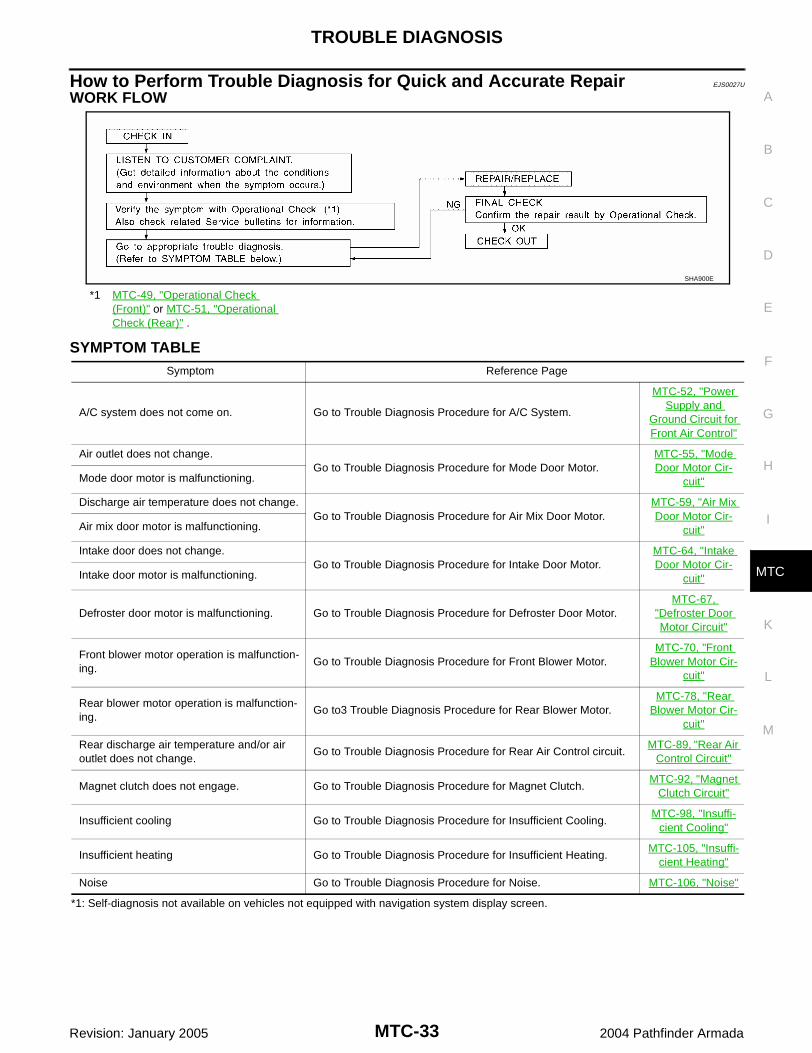
How to Perform Trouble Diagnosis for Quick and Accurate Repair ...................................................... 33

MTC-2Revision: January 2005 2004 Pathfinder Armada
WORK FLOW ...................................................... 33SYMPTOM TABLE .............................................. 33
Component Parts and Harness Connector Location ... 34ENGINE COMPARTMENT .................................. 34FRONT PASSENGER COMPARTMENT ............ 35REAR PASSENGER COMPARTMENT ............... 36
Schematic ............................................................... 37Wiring Diagram — A/C,M — ................................... 38Front Air Control Terminals and Reference Value ... 47
PIN CONNECTOR TERMINAL LAYOUT ............ 47TERMINALS AND REFERENCE VALUE FOR FRONT AIR CONTROL ....................................... 47
Operational Check (Front) ...................................... 49CHECKING BLOWER ......................................... 49CHECKING DISCHARGE AIR ............................ 49CHECKING RECIRCULATION ............................ 49CHECKING TEMPERATURE DECREASE ......... 50CHECKING TEMPERATURE INCREASE .......... 50CHECK A/C SWITCH .......................................... 50
Operational Check (Rear) ....................................... 51CHECKING BLOWER ......................................... 51CHECKING TEMPERATURE DECREASE ......... 51CHECKING TEMPERATURE INCREASE .......... 51
Power Supply and Ground Circuit for Front Air Con-trol ........................................................................... 52
INSPECTION FLOW ........................................... 52COMPONENT DESCRIPTION ............................ 53DIAGNOSTIC PROCEDURE FOR A/C SYSTEM ... 53
Mode Door Motor Circuit ........................................ 55INSPECTION FLOW ........................................... 55SYSTEM DESCRIPTION .................................... 56COMPONENT DESCRIPTION ............................ 56DIAGNOSTIC PROCEDURE FOR MODE DOOR MOTOR ................................................... 57
Air Mix Door Motor Circuit ...................................... 59INSPECTION FLOW ........................................... 59SYSTEM DESCRIPTION .................................... 60COMPONENT DESCRIPTION ............................ 60DIAGNOSTIC PROCEDURE FOR AIR MIX DOOR MOTOR (FRONT) .................................... 61DIAGNOSTIC PROCEDURE FOR AIR MIX DOOR MOTOR (REAR) ...................................... 62
Intake Door Motor Circuit ........................................ 64INSPECTION FLOW ........................................... 64SYSTEM DESCRIPTION .................................... 65COMPONENT DESCRIPTION ............................ 65DIAGNOSTIC PROCEDURE FOR INTAKE DOOR MOTOR ................................................... 66
Defroster Door Motor Circuit ................................... 67SYMPTOM: .......................................................... 67INSPECTION FLOW ........................................... 67SYSTEM DESCRIPTION .................................... 68COMPONENT DESCRIPTION ............................ 68DIAGNOSTIC PROCEDURE FOR DEFROSTER DOOR MOTOR ............................ 68
Front Blower Motor Circuit ...................................... 70INSPECTION FLOW ........................................... 70SYSTEM DESCRIPTION .................................... 71COMPONENT DESCRIPTION ............................ 71
DIAGNOSTIC PROCEDURE FOR BLOWER MOTOR ................................................................72COMPONENT INSPECTION ...............................76
Rear Blower Motor Circuit .......................................78INSPECTION FLOW ............................................78SYSTEM DESCRIPTION .....................................79DIAGNOSTIC PROCEDURE FOR REAR BLOWER MOTOR ...............................................79COMPONENT INSPECTION ...............................87
Rear Air Control Circuit ...........................................89INSPECTION FLOW ............................................89SYSTEM DESCRIPTION .....................................90DIAGNOSTIC PROCEDURE FOR REAR AIR CONTROL ...........................................................90
Magnet Clutch Circuit ..............................................92INSPECTION FLOW ............................................92SYSTEM DESCRIPTION .....................................93DIAGNOSTIC PROCEDURE FOR MAGNET CLUTCH ..............................................................93COMPONENT INSPECTION ...............................97
Insufficient Cooling ..................................................98INSPECTION FLOW ............................................98PERFORMANCE TEST DIAGNOSES ................99PERFORMANCE CHART ..................................101TROUBLE DIAGNOSES FOR UNUSUAL PRES-SURE .................................................................102
Insufficient Heating ...............................................105INSPECTION FLOW ..........................................105
Noise .....................................................................106INSPECTION FLOW ..........................................106
Water Valve Circuit ................................................107COMPONENT DESCRIPTION ..........................107DIAGNOSTIC PROCEDURE FOR WATER VALVE ................................................................107COMPONENT INSPECTION .............................109
Intake Sensor Circuit .............................................109COMPONENT DESCRIPTION ..........................109DIAGNOSTIC PROCEDURE FOR INTAKE SEN-SOR ...................................................................109COMPONENT INSPECTION ............................. 111
CONTROL UNIT ......................................................112Removal and Installation ....................................... 112
FRONT AIR CONTROL ..................................... 112REAR AIR CONTROL ....................................... 112
INTAKE SENSOR ....................................................113Removal and Installation ....................................... 113
REMOVAL .......................................................... 113INSTALLATION .................................................. 113
BLOWER MOTOR ...................................................114Components .......................................................... 114Removal and Installation ....................................... 114
FRONT BLOWER MOTOR ................................ 114REAR BLOWER MOTOR .................................. 115
IN-CABIN MICROFILTER ........................................116Removal and Installation ....................................... 116
FUNCTION ........................................................ 116REPLACEMENT TIMING .................................. 116REPLACEMENT PROCEDURE ........................ 116
HEATER & COOLING UNIT ASSEMBLY ...............118

MTC-3
C
D
E
F
G
H
I
K
L
M
A
B
MTC
Revision: January 2005 2004 Pathfinder Armada
Components ..........................................................118Removal and Installation .......................................119
FRONT HEATER AND COOLING UNIT ASSEM-BLY .....................................................................119REAR HEATER AND COOLING UNIT ASSEM-BLY .................................................................... 120
HEATER CORE ...................................................... 121Components ......................................................... 121Removal and Installation ...................................... 122
FRONT HEATER CORE ................................... 122REAR HEATER CORE ..................................... 123
DEFROSTER DOOR MOTOR ................................ 124Removal and Installation ...................................... 124
REMOVAL ......................................................... 124INSTALLATION ................................................. 124
INTAKE DOOR MOTOR ......................................... 125Removal and Installation ...................................... 125
REMOVAL ......................................................... 125INSTALLATION ................................................. 125
MODE DOOR MOTOR ........................................... 126Removal and Installation ...................................... 126
REMOVAL ......................................................... 126INSTALLATION ................................................. 126
AIR MIX DOOR MOTOR ......................................... 127Components ......................................................... 127Removal and Installation ...................................... 127
FRONT AIR MIX DOOR MOTOR ..................... 127REAR AIR MIX DOOR MOTOR ........................ 128
FRONT BLOWER MOTOR RESISTOR ................. 129Removal and Installation ...................................... 129
REMOVAL ......................................................... 129INSTALLATION ................................................. 129
REAR BLOWER MOTOR RESISTOR ................... 130Removal and Installation ...................................... 130
REMOVAL ......................................................... 130INSTALLATION ................................................. 130
DUCTS AND GRILLES .......................................... 131Components ......................................................... 131Removal and Installation ...................................... 134
CENTER CONSOLE HEAT DUCT AND REAR FINISHER ASSEMBLY GRILLE ....................... 134DEFROSTER NOZZLE ..................................... 134RH AND LH SIDE DEMISTER DUCT ............... 134RH AND LH VENTILATOR DUCT ..................... 134CENTER VENTILATOR DUCT ......................... 134FLOOR DUCT ................................................... 134REAR OVERHEAD DUCTS .............................. 134REAR FLOOR DUCT ........................................ 135GRILLES ........................................................... 135
REFRIGERANT LINES ........................................... 136HFC-134a (R-134a) Service Procedure ............... 136
SETTING OF SERVICE TOOLS AND EQUIP-MENT ................................................................ 136
Components ......................................................... 138Removal and Installation for Compressor ............ 140
REMOVAL ......................................................... 140INSTALLATION ................................................. 141
Removal and Installation for Compressor Clutch . 141REMOVAL ......................................................... 141INSPECTION .................................................... 142INSTALLATION ................................................. 142BREAK-IN OPERATION .................................... 144
Removal and Installation for Low-pressure Flexible Hose ..................................................................... 144
REMOVAL ......................................................... 144INSTALLATION ................................................. 144
Removal and Installation for High-pressure Flexible Hose ..................................................................... 144
REMOVAL ......................................................... 144INSTALLATION ................................................. 144
Removal and Installation for High-pressure Pipe . 144REMOVAL ......................................................... 144INSTALLATION ................................................. 144
Removal and Installation for Low-pressure Pipe .. 145REMOVAL ......................................................... 145INSTALLATION ................................................. 145
Removal and Installation for Refrigerant Pressure Sensor .................................................................. 145
REMOVAL ......................................................... 145INSTALLATION ................................................. 145
Removal and Installation for Condenser .............. 145REMOVAL ......................................................... 145INSTALLATION ................................................. 146
Removal and Installation for Front Evaporator ..... 147REMOVAL ......................................................... 147INSTALLATION ................................................. 148
Removal and Installation for Rear Evaporator ...... 148REMOVAL ......................................................... 149INSTALLATION ................................................. 149
Removal and Installation for Front Expansion Valve . 149REMOVAL ......................................................... 149INSTALLATION ................................................. 149
Removal and Installation for Rear Expansion Valve . 149REMOVAL ......................................................... 149INSTALLATION ................................................. 150
Checking for Refrigerant Leaks ............................ 150Checking System for Leaks Using the Fluorescent Dye Leak Detector ................................................ 150Dye Injection ......................................................... 150Electronic Refrigerant Leak Detector .................... 151
PRECAUTIONS FOR HANDLING LEAK DETECTOR ....................................................... 151CHECKING PROCEDURE ............................... 152
SERVICE DATA AND SPECIFICATIONS (SDS) .... 154Service Data and Specifications (SDS) ................ 154
COMPRESSOR ................................................ 154LUBRICANT ...................................................... 154REFRIGERANT ................................................. 154ENGINE IDLING SPEED .................................. 154BELT TENSION ................................................. 154

MTC-4
PRECAUTIONS
Revision: January 2005 2004 Pathfinder Armada
PRECAUTIONS PFP:00001
Precautions for Supplemental Restraint System (SRS) “AIR BAG” and “SEAT BELT PRE-TENSIONER” EJS00274
The Supplemental Restraint System such as “AIR BAG” and “SEAT BELT PRE-TENSIONER”, used alongwith a front seat belt, helps to reduce the risk or severity of injury to the driver and front passenger for certaintypes of collision. This system includes seat belt switch inputs and dual stage front air bag modules. The SRSsystem uses the seat belt switches to determine the front air bag deployment, and may only deploy one frontair bag, depending on the severity of a collision and whether the front occupants are belted or unbelted.Information necessary to service the system safely is included in the SRS and SB section of this Service Man-ual.WARNING: To avoid rendering the SRS inoperative, which could increase the risk of personal injury or death
in the event of a collision which would result in air bag inflation, all maintenance must be per-formed by an authorized NISSAN/INFINITI dealer.
Improper maintenance, including incorrect removal and installation of the SRS, can lead to per-sonal injury caused by unintentional activation of the system. For removal of Spiral Cable and AirBag Module, see the SRS section.
Do not use electrical test equipment on any circuit related to the SRS unless instructed to in thisService Manual. SRS wiring harnesses can be identified by yellow and/or orange harnesses orharness connectors.
Precautions for Working with HFC-134a (R-134a) EJS00275
WARNING: CFC-12 (R-12) refrigerant and HFC-134a (R-134a) refrigerant are not compatible. If the refrigerants
are mixed compressor failure is likely to occur. Refer to MTC-4, "Contaminated Refrigerant" . Todetermine the purity of HFC-134a (R-134a) in the vehicle and recovery tank, use RefrigerantRecovery/Recycling Recharging equipment and Refrigerant Identifier.
Use only specified lubricant for the HFC-134a (R-134a) A/C system and HFC-134a (R-134a) compo-nents. If lubricant other than that specified is used, compressor failure is likely to occur.
The specified HFC-134a (R-134a) lubricant rapidly absorbs moisture from the atmosphere. The fol-lowing handling precautions must be observed:
– When removing refrigerant components from a vehicle, immediately cap (seal) the component tominimize the entry of moisture from the atmosphere.
– When installing refrigerant components to a vehicle, do not remove the caps (unseal) until justbefore connecting the components. Connect all refrigerant loop components as quickly as possi-ble to minimize the entry of moisture into system.
– Only use the specified lubricant from a sealed container. Immediately reseal containers of lubri-cant. Without proper sealing, lubricant will become moisture saturated and should not be used.
– Avoid breathing A/C refrigerant and lubricant vapor or mist. Exposure may irritate eyes, nose andthroat. Remove HFC-134a (R-134a) from the A/C system using certified service equipment meetingrequirements of SAE J2210 [HFC-134a (R-134a) recycling equipment], or J2209 [HFC-134a (R-134a)recovery equipment]. If accidental system discharge occurs, ventilate work area before resumingservice. Additional health and safety information may be obtained from refrigerant and lubricantmanufacturers.
– Do not allow lubricant, NISSAN A/C System Lubricant Type S (DH-PS) or equivalent, to come incontact with styrofoam parts. Damage may result.
Contaminated Refrigerant EJS00276
If a refrigerant other than pure HFC-134a (R-134a) is identified in a vehicle, your options are: Explain to the customer that environmental regulations prohibit the release of contaminated refrigerant
into the atmosphere. Explain that recovery of the contaminated refrigerant could damage your service equipment and refriger-
ant supply. Suggest the customer return the vehicle to the location of previous service where the contamination may
have occurred.

PRECAUTIONS
MTC-5
C
D
E
F
G
H
I
K
L
M
A
B
MTC
Revision: January 2005 2004 Pathfinder Armada
If you choose to perform the repair, recover the refrigerant using only dedicated equipment and contain-ers. Do not recover contaminated refrigerant into your existing service equipment. If your facilitydoes not have dedicated recovery equipment, you may contact a local refrigerant product retailer for avail-able service. This refrigerant must be disposed of in accordance with all federal and local regulations. Inaddition, replacement of all refrigerant system components on the vehicle is recommended.
If the vehicle is within the warranty period, the air conditioner warranty is void. Please contact NISSANCustomer Affairs for further assistance.
General Refrigerant Precautions EJS00277
WARNING: Do not release refrigerant into the air. Use approved recovery/recycling equipment to capture the
refrigerant every time an air conditioning system is discharged. Always wear eye and hand protection (goggles and gloves) when working with any refrigerant or
air conditioning system. Do not store or heat refrigerant containers above 52°C (125°F). Do not heat a refrigerant container with an open flame; if container warming is required, place the
bottom of the container in a warm pail of water. Do not intentionally drop, puncture, or incinerate refrigerant containers. Keep refrigerant away from open flames: poisonous gas will be produced if refrigerant burns. Refrigerant will displace oxygen, therefore be certain to work in well ventilated areas to prevent
suffocation. Do not pressure test or leak test HFC-134a (R-134a) service equipment and/or vehicle air condi-
tioning systems with compressed air during repair. Some mixtures of air and HFC-134a (R-134a)have been shown to be combustible at elevated pressures. These mixtures, if ignited, may causeinjury or property damage. Additional health and safety information may be obtained from refriger-ant manufacturers.
Precautions for Leak Detection Dye EJS00278
The A/C system contains a fluorescent leak detection dye used for locating refrigerant leaks. An ultraviolet(UV) lamp is required to illuminate the dye when inspecting for leaks.
Always wear fluorescence enhancing UV safety goggles to protect your eyes and enhance the visibility ofthe fluorescent dye.
The fluorescent dye leak detector is not a replacement for an electronic refrigerant leak detector. The fluo-rescent dye leak detector should be used in conjunction with an electronic refrigerant leak detector (J-41995).
For your safety and the customer's satisfaction, read and follow all manufacturer's operating instructionsand precautions prior to performing work.
A compressor shaft seal should not be repaired because of dye seepage. The compressor shaft sealshould only be repaired after confirming the leak with an electronic refrigerant leak detector (J-41995).
Always remove any dye from the leak area after repairs are complete to avoid a misdiagnosis during afuture service.
Do not allow dye to come into contact with painted body panels or interior components. If dye is spilled,clean immediately with the approved dye cleaner. Fluorescent dye left on a surface for an extended periodof time cannot be removed .
Do not spray the fluorescent dye cleaning agent on hot surfaces (engine exhaust manifold, etc.). Do not use more than one refrigerant dye bottle (1/4 ounce / 7.4 cc) per A/C system. Leak detection dyes for HFC-134a (R-134a) and CFC-12 (R-12) A/C systems are different. Do not use
HFC-134a (R-134a) leak detection dye in CFC-12 (R-12) A/C systems or CFC-12 (R-12) leak detectiondye in HFC-134a (R-134a) A/C systems or A/C system damage may result.
The fluorescent properties of the dye will remain for over three (3) years unless a compressor failureoccurs.

MTC-6
PRECAUTIONS
Revision: January 2005 2004 Pathfinder Armada
A/C Identification Label EJS00279
Vehicles with factory installed fluorescent dye have this identificationlabel on the underside of hood.
Precautions for Refrigerant Connection EJS0027A
A new type refrigerant connection has been introduced to all refrigerant lines except the following locations. Expansion valve to cooling unit Evaporator pipes to evaporator (inside cooling unit) Refrigerant pressure sensor
FEATURES OF NEW TYPE REFRIGERANT CONNECTION The O-ring has been relocated. It has also been provided with a groove for proper installation. This
reduces the possibility of the O-ring being caught in, or damaged by, the mating part. The sealing directionof the O-ring is now set vertically in relation to the contacting surface of the mating part to improve sealingcharacteristics.
The reaction force of the O-ring will not occur in the direction that causes the joint to pull out, thereby facil-itating piping connections.
WJIA0672E
SHA815E
PRECAUTIONS
MTC-7
C
D
E
F
G
H
I
K
L
M
A
B
MTC
Revision: January 2005 2004 Pathfinder Armada
O-RING AND REFRIGERANT CONNECTION
Front A/C Compressor and Condenser
WJIA1578E

MTC-8
PRECAUTIONS
Revision: January 2005 2004 Pathfinder Armada
Rear A/C
CAUTION:The new and former refrigerant connections use different O-ring configurations. Do not confuse O-rings since they are not interchangeable. If a wrong O-ring is installed, refrigerant will leak at oraround the connection.
1. High-pressure service valve 2. Grommet 3. High-pressure pipe
4. Refrigerant pressure sensor 5. Condenser 6. Compressor shaft seal
7. High-pressure flexible hose 8. Low-pressure flexible hose 9. Low-pressure service valve
10. Low-pressure pipe 11. Expansion valve (front) 12. Drain hose
WJIA0955E

PRECAUTIONS
MTC-9
C
D
E
F
G
H
I
K
L
M
A
B
MTC
Revision: January 2005 2004 Pathfinder Armada
O-Ring Part Numbers and Specifications
*: Always check with the Parts Department for the latest parts information.
WARNING:Make sure all refrigerant is discharged into the recycling equipment and the pressure in the system isless than atmospheric pressure. Then gradually loosen the discharge side hose fitting and remove it.CAUTION:When replacing or cleaning refrigerant cycle components, observe the following. When the compressor is removed, store it in the same position as it is when mounted on the car.
Failure to do so will cause lubricant to enter the low pressure chamber. When connecting tubes, always use a torque wrench and a back-up wrench. After disconnecting tubes, immediately plug all openings to prevent entry of dirt and moisture. When installing an air conditioner in the vehicle, connect the pipes as the final stage of the opera-
tion. Do not remove the seal caps of pipes and other components until just before required forconnection.
Allow components stored in cool areas to warm to working area temperature before removing sealcaps. This prevents condensation from forming inside A/C components.
Thoroughly remove moisture from the refrigeration system before charging the refrigerant. Always replace used O-rings. When connecting tube, apply lubricant to circle of the O-rings shown in illustration. Be careful not
to apply lubricant to threaded portion.Lubricant name: NISSAN A/C System Lubricant Type S (DH-PS) or equivalentPart number: KLH00-PAGS0
O-ring must be closely attached to dented portion of tube. When replacing the O-ring, be careful not to damage O-ring and tube. Connect tube until you hear it click, then tighten the nut or bolt by hand until snug. Make sure that
the O-ring is installed to tube correctly.
Connec-tion type
O-ring size
Part number* D mm (in) W mm (in)
New 8 92471 N8210 6.8 (0.268) 1.85 (0.0728)
Former 10 J2476 89956 9.25 (0.3642) 1.78 (0.0701)
New12
92472 N8210 10.9 (0.429) 2.43 (0.0957)
Former 92475 71L00 11.0 (0.433) 2.4 (0.094)
New16
92473 N8210 13.6 (0.535) 2.43 (0.0957)
Former 92475 72L00 14.3 (0.563) 2.3 (0.091)
New19
92474 N8210 16.5 (0.650) 2.43 (0.0957)
Former 92477 N8200 17.12 (0.6740) 1.78 (0.0701)
New 24 92195 AH300 21.8 (0.858) 2.4 (0.094)
SHA814E

MTC-10
PRECAUTIONS
Revision: January 2005 2004 Pathfinder Armada
After connecting line, conduct leak test and make sure that there is no leakage from connections.When the gas leaking point is found, disconnect that line and replace the O-ring. Then tighten con-nections of seal seat to the specified torque.
Precautions for Servicing Compressor EJS0027B
Plug all openings to prevent moisture and foreign matter from entering. When the compressor is removed, store it in the same position as it is when mounted on the car. When replacing or repairing compressor, follow “Maintenance of Lubricant Quantity in Compres-
sor” exactly. Refer to MTC-21, "Maintenance of Lubricant Quantity in Compressor" . Keep friction surfaces between clutch and pulley clean. If the surface is contaminated with lubri-
cant, wipe it off by using a clean waste cloth moistened with thinner. After compressor service operation, turn the compressor shaft by hand more than 5 turns in both
directions. This will equally distribute lubricant inside the compressor. After the compressor isinstalled, let the engine idle and operate the compressor for 1 hour.
After replacing the compressor magnet clutch, apply voltage to the new one and check for normaloperation. Refer to MTC-141, "Removal and Installation for Compressor Clutch"
Precautions for Service Equipment EJS0027C
RECOVERY/RECYCLING EQUIPMENTFollow the manufacturer's instructions for machine operation and machine maintenance. Never introduce anyrefrigerant other than that specified into the machine.
ELECTRONIC LEAK DETECTORFollow the manufacturer's instructions for tester operation and tester maintenance.
RHA861F

PRECAUTIONS
MTC-11
C
D
E
F
G
H
I
K
L
M
A
B
MTC
Revision: January 2005 2004 Pathfinder Armada
VACUUM PUMPThe lubricant contained inside the vacuum pump is not compatiblewith the specified lubricant for HFC-134a (R-134a) A/C systems.The vent side of the vacuum pump is exposed to atmospheric pres-sure so the vacuum pump lubricant may migrate out of the pump intothe service hose. This is possible when the pump is switched offafter evacuation (vacuuming) and hose is connected to it.To prevent this migration, use a manual valve situated near thehose-to-pump connection, as follows. Usually vacuum pumps have a manual isolator valve as part of
the pump. Close this valve to isolate the service hose from thepump.
For pumps without an isolator, use a hose equipped with a man-ual shut-off valve near the pump end. Close the valve to isolatethe hose from the pump.
If the hose has an automatic shut off valve, disconnect the hosefrom the pump: as long as the hose is connected, the valve isopen and lubricating oil may migrate.
Some one-way valves open when vacuum is applied and closeunder a no vacuum condition. Such valves may restrict the pump'sability to pull a deep vacuum and are not recommended.
MANIFOLD GAUGE SETBe certain that the gauge face indicates HFC-134a (R-134a or134a). Make sure the gauge set has 1/2″-16 ACME threaded con-nections for service hoses. Confirm the set has been used only withrefrigerant HFC-134a (R-134a) along with specified lubricant.
SERVICE HOSESBe certain that the service hoses display the markings described(colored hose with black stripe). All hoses must include positive shut-off devices (either manual or automatic) near the end of the hosesopposite the manifold gauge.
RHA270D
SHA533D
RHA272D

MTC-12
PRECAUTIONS
Revision: January 2005 2004 Pathfinder Armada
SERVICE COUPLERSNever attempt to connect HFC-134a (R-134a) service couplers to aCFC-12 (R-12) A/C system. The HFC-134a (R-134a) couplers willnot properly connect to the CFC-12 (R-12) system. If an improperconnection is attempted, discharging and contamination may occur.
REFRIGERANT WEIGHT SCALEVerify that no refrigerant other than HFC134a (R-134a) and specifiedlubricants have been used with the scale. If the scale controls refrig-erant flow electronically, the hose fitting must be 1/2”-16 ACME.
CHARGING CYLINDERUsing a charging cylinder is not recommended. Refrigerant may be vented into air from cylinder's top valvewhen filling the cylinder with refrigerant. Also, the accuracy of the cylinder is generally less than that of anelectronic scale or of quality recycle/recharge equipment.
Wiring Diagrams and Trouble Diagnosis EJS0027D
When you read wiring diagrams, refer to the following: GI-15, "How to Read Wiring Diagrams" PG-4, "POWER SUPPLY ROUTING CIRCUIT"When you perform trouble diagnosis, refer to the following: GI-9, "How to Follow Trouble Diagnoses" GI-27, "How to Perform Efficient Diagnosis for an Electrical Incident"
Shut-off valve rotation A/C service valve
Clockwise Open
Counterclockwise Close
RHA273D
RHA274D

PREPARATION
MTC-13
C
D
E
F
G
H
I
K
L
M
A
B
MTC
Revision: January 2005 2004 Pathfinder Armada
PREPARATION PFP:00002
Special Service Tools EJS0027E
The actual shapes of Kent-Moore tools may differ from those of special service tools illustrated here.
HFC-134a (R-134a) Service Tools and Equipment EJS0027F
Never mix HFC-134a (R-134a) refrigerant and/or its specified lubricant with CFC-12 (R-12) refrigerant and/orits lubricant.Separate and non-interchangeable service equipment must be used for handling each type of refrigerant/lubri-cant.Refrigerant container fittings, service hose fittings and service equipment fittings (equipment which handlesrefrigerant and/or lubricant) are different between CFC-12 (R-12) and HFC-134a (R-134a). This is to avoidmixed use of the refrigerants/lubricant.Adapters that convert one size fitting to another must never be used refrigerant/lubricant contamination willoccur and compressor failure will result.
Tool number(Kent-Moore No.)Tool name
Description
—(J-38873-A)Pulley installer
Installing pulley
KV99233130(J-29884)Pulley puller
Removing pulley
LHA171
LHA172
Tool number(Kent-Moore No.)Tool name
Description
HFC-134a (R-134a) refrigerant Container color: Light blueContainer marking: HFC-134a (R-134a)Fitting size: Thread size
large container 1/2”-16 ACME
KLH00-PAGS0( — )NISSAN A/C System Lubricant Type S (DH-PS)
Type: Poly alkylene glycol oil (PAG), type S (DH-PS)Application: HFC-134a (R-134a) swash plate compressors (NISSAN only)Lubricity: 40 m (1.4 US fl oz, 1.4 Imp fl oz)
(ACR2005-NI)ACR5 A/C Service Center
Refrigerant recovery/recycling and re-charging
S-NT196
S-NT197
WJIA0293E

MTC-14
PREPARATION
Revision: January 2005 2004 Pathfinder Armada
(J-41995)Electronic refrigerant leak detector
Power supply:
DC 12V (Battery terminal)
(J-43926)Refrigerant dye leak detection kitKit includes:(J-42220) UV lamp and UV safety goggles(J-41459) Refrigerant dye injector(J-41447) qty. 24HFC-134a (R-134a) refrigerant dye(J-43872) Refrigerant dye cleaner
Power supply:
DC 12V (Battery terminal)
(J-42220)Fluorescent dye leak detector
Power supply:
DC 12V (Battery terminal)
For checking refrigerant leak when flu-orescent dye is installed in A/C system.Includes: UV lamp and UV safety gog-gles
(J-41447)HFC-134a (R-134a) Fluorescent leak detection dye(Box of 24, 1/4 ounce bottles)
Application: For HFC-134a (R-134a) PAG oilContainer: 1/4 ounce (7.4cc) bottle(Includes self-adhesive dye identifica-tion labels for affixing to vehicle after charging system with dye.)
(J-41459)HFC-134a (R-134a) Dye injectorUse with J-41447, 1/4 ounce bottle
For injecting 1/4 ounce of fluorescent leak detection dye into A/C system.
(J-43872)Refrigerant dye cleaner
For cleaning dye spills.
Tool number(Kent-Moore No.)Tool name
Description
AHA281A
ZHA200H
SHA438F
SHA439F
SHA440F
SHA441F

PREPARATION
MTC-15
C
D
E
F
G
H
I
K
L
M
A
B
MTC
Revision: January 2005 2004 Pathfinder Armada
Commercial Service Tools EJS0027G
(J-39183-C)Manifold gauge set (with hoses and couplers)
Identification:
The gauge face indicates R-134a.Fitting size-Thread size
1/2”-16 ACME
Service hoses
High side hose(J-39500-72B)
Low side hose(J-39500-72R)
Utility hose(J-39500-72Y)
Hose color
Low side hose: Blue with black stripe
High side hose: Red with black stripe
Utility hose: Yellow with black stripe or green with black stripeHose fitting to gauge:
1/2”-16 ACME
Service couplers
High side coupler(J-39500-20A)
Low side coupler(J-39500-24A)
Hose fitting to service hose:
M14 x 1.5 fitting is optional or perma-nently attached.
(J-39699)Refrigerant weight scale
For measuring of refrigerantFitting size-Thread size
1/2”-16 ACME
(J-39649)Vacuum pump(Including the isolator valve)
Capacity:
Air displacement: 4 CFM
Micron rating: 20 microns
Oil capacity: 482 g (17 oz)Fitting size-Thread size
1/2”-16 ACME
Tool number(Kent-Moore No.)Tool name
Description
RJIA0196E
S-NT201
S-NT202
S-NT200
S-NT203

MTC-16
PREPARATION
Revision: January 2005 2004 Pathfinder Armada
Tool name Description
(J-41810-NI)Refrigerant identifier equipment- (R-134a)
For checking refrigerant purity and system contamination
Power tool Loosening bolts and nuts
(J-44614)Clutch disc holding tool
Clutch disc holding tool
RJIA0197E
PBIC0190E
WHA230
REFRIGERATION SYSTEM
MTC-17
C
D
E
F
G
H
I
K
L
M
A
B
MTC
Revision: January 2005 2004 Pathfinder Armada
REFRIGERATION SYSTEM PFP:KA990
Refrigerant Cycle EJS0027H
REFRIGERANT FLOWThe refrigerant flows in the standard pattern, that is, through the compressor, the condenser with liquid tank,through the front and rear evaporators, and back to the compressor. The refrigerant evaporation through theevaporator coils are controlled by front and rear externally equalized expansion valves, located inside the frontand rear evaporator cases.
Refrigerant System Protection EJS0027I
REFRIGERANT PRESSURE SENSORThe refrigerant system is protected against excessively high or low pressures by the refrigerant pressure sen-sor, located on the condenser. If the system pressure rises above or falls below the specifications, the refriger-ant pressure sensor detects the pressure inside the refrigerant line and sends a voltage signal to the ECM.The ECM de-energizes the A/C relay to disengage the magnetic compressor clutch when pressure on the highpressure side detected by refrigerant pressure sensor is over about 2,746 kPa (28 kg/cm2 , 398 psi), or belowabout 120 kPa (1.22 kg/cm2 , 17.4 psi).

MTC-18
REFRIGERATION SYSTEM
Revision: January 2005 2004 Pathfinder Armada
PRESSURE RELIEF VALVEThe refrigerant system is also protected by a pressure relief valve, located in the rear head of the compressor.When the pressure of refrigerant in the system increases to an abnormal level [more than 2,990 kPa (30.5 kg/cm2 , 433.6 psi)], the release port on the pressure relief valve automatically opens and releases refrigerantinto the atmosphere.
WJIA1342E

REFRIGERATION SYSTEM
MTC-19
C
D
E
F
G
H
I
K
L
M
A
B
MTC
Revision: January 2005 2004 Pathfinder Armada
Component Layout EJS0027J
FRONT REFRIGERATION SYSTEM
WJIA0956E

MTC-20
REFRIGERATION SYSTEM
Revision: January 2005 2004 Pathfinder Armada
REAR REFRIGERATION SYSTEM
1. Defroster nozzle 2. LH side demister duct 3. LH ventilator duct
4. RH side demister duct 5. RH ventilator duct 6. Center ventilator duct
7. Front heater and cooling unit assembly 8. Floor duct 9. Clips
10. Heat duct
1. Rear floor duct 2. Rear heater and cooling unit assembly 3. Rear lower overhead duct
4. Rear upper overhead duct
LJIA0142E

LUBRICANT
MTC-21
C
D
E
F
G
H
I
K
L
M
A
B
MTC
Revision: January 2005 2004 Pathfinder Armada
LUBRICANT PFP:KLG00
Maintenance of Lubricant Quantity in Compressor EJS0027K
The lubricant in the compressor circulates through the system with the refrigerant. Add lubricant to compres-sor when replacing any component or after a large refrigerant leakage has occurred. It is important to maintainthe specified amount.If lubricant quantity is not maintained properly, the following malfunctions may result: Lack of lubricant: May lead to a seized compressor Excessive lubricant: Inadequate cooling (thermal exchange interference)
LUBRICANTName: NISSAN A/C System Lubricant Type S (DH-PS)Part number: KLH00-PAGS0
CHECKING AND ADJUSTINGCAUTION:If excessive lubricant leakage is noted, do not perform the lubricant return operation.Start the engine and set the following conditions:test condition Engine speed: Idling to 1,200 rpm A/C switch: On Blower speed: Max. position Temp. control: Optional [Set so that intake air temperature is 25° to 30° C (77° to 86°F).] Intake position: Recirculation ( ) Perform lubricant return operation for about ten minutesAdjust the lubricant quantity according to the following table.
Lubricant Adjusting Procedure for Components Replacement Except CompressorAfter replacing any of the following major components, add the correct amount of lubricant to the system.Amount of lubricant to be added
*1: If refrigerant leak is small, no addition of lubricant is needed.
Lubricant Adjustment Procedure for Compressor Replacement1. Before connecting recovery/recycling equipment to vehicle, check recovery/recycling equipment gauges.
No refrigerant pressure should be displayed. If NG, recover refrigerant from equipment lines.2. Connect recovery/recycling equipment to vehicle. Confirm refrigerant purity in supply tank using recovery/
recycling equipment and refrigerant identifier. If NG, refer to MTC-4, "Contaminated Refrigerant" .3. Confirm refrigerant purity in vehicle A/C system using recovery/recycling equipment and refrigerant identi-
fier. If NG, refer to MTC-4, "Contaminated Refrigerant" .4. Discharge refrigerant into the refrigerant recovery/recycling equipment. Measure lubricant discharged into
the recovery/recycling equipment.5. Drain the lubricant from the “old” (removed) compressor into a graduated container and recover the
amount of lubricant drained.6. Drain the lubricant from the “new” compressor into a separate, clean container.
Part replaced
Lubricant to be added to system
RemarksAmount of lubricant
m (US fl oz, Imp fl oz)
Front evaporator 75 (2.5, 2.6) —
Rear evaporator 75 (2.5, 2.6) —
Condenser 75 (2.5, 2.6) —
Liquid tank 5 (0.2, 0.2) Add if compressor is not replaced.
In case of refrigerant leak30 (1.0, 1.1) Large leak
— Small leak *1

MTC-22
LUBRICANT
Revision: January 2005 2004 Pathfinder Armada
7. Measure an amount of new lubricant installed equal to amount drained from “old” compressor. Add thislubricant to “new” compressor through the suction port opening.
8. Measure an amount of new lubricant equal to the amount recovered during discharging. Add this lubricantto “new” compressor through the suction port opening.
9. If the liquid tank also needs to be replaced, add an additional 5 m (0.2 US fl oz, 0.2 Imp fl oz) of lubricantat this time.Do not add this 5 m (0.2 US fl oz, 0.2 Imp fl oz) of lubricant if only replacing the compressor.
RHA065DD

AIR CONDITIONER CONTROL
MTC-23
C
D
E
F
G
H
I
K
L
M
A
B
MTC
Revision: January 2005 2004 Pathfinder Armada
AIR CONDITIONER CONTROL PFP:27500
Description EJS0028L
The front air control provides regulation of the vehicle's interior temperature. The system is based on the posi-tion of the front air controls temperature switch selected by the driver. This is done by utilizing a microcom-puter, also referred to as the front air control, which receives input signals from the following two sensors: Intake sensor PBR (position balanced resistor).The front air control uses these signals (including the set position of the temperature switch) to control: Outlet air volume Air temperature Air distributionThe front air control also provides separate regulation of the vehicle's interior temperature for the rear passen-ger area. The system is based on the temperature and rear blower settings selected from rear controlswitches located on the front air control, or from the temperature and rear blower settings selected from rearcontrol switches on the rear air control, when the front air control switches are set to the rear position.The front air control is used to select: Outlet air volume Air temperature/distribution
Operation EJS0028M
AIR MIX DOOR CONTROLThe air mix door is controlled so that in-vehicle temperature changed based on the position of the temperatureswitch.
BLOWER SPEED CONTROLBlower speed is controlled based on front and rear blower switch settings.When blower switch is turned, the blower motor starts and increases air flow volume each time the blowerswitch is turned counterclockwise, and decreases air flow volume each time the blower switch is turned coun-terclockwise.When engine coolant temperature is low, the blower motor operation is delayed to prevent cool air from flow-ing.
INTAKE DOORS CONTROLThe intake doors are controlled by the recirculation switch setting, and the mode (defroster) switch setting.
MODE DOOR CONTROLThe mode door is controlled by the position of the mode switch.
DEFROSTER DOOR CONTROLThe defroster door is controlled by: Turning the defroster dial to front defroster.

MTC-24
AIR CONDITIONER CONTROL
Revision: January 2005 2004 Pathfinder Armada
MAGNET CLUTCH CONTROL
When the A/C switch is pressed, or the mode switch is turned to the defroster position, the front air control out-puts a compressor ON signal to BCM.The BCM then sends a compressor ON signal to ECM, via CAN communication line.ECM judges whether compressor can be turned ON, based on each sensor status (refrigerant pressure sen-sor signal, throttle angle sensor, etc.). If it judges compressor can be turned ON, it sends compressor ON sig-nal to IPDM E/R, via CAN communication line.Upon receipt of compressor ON signal from ECM, IPDM E/R turns air conditioner relay ON to operate com-pressor.
WJIA0682E

AIR CONDITIONER CONTROL
MTC-25
C
D
E
F
G
H
I
K
L
M
A
B
MTC
Revision: January 2005 2004 Pathfinder Armada
Description of Control System EJS0028N
The control system consists of input sensors, switches, the front air control (microcomputer) and outputs.The relationship of these components is shown in the figure below:
Control Operation EJS0028O
Front air control
WJIA0683E
WJIA0485E

MTC-26
AIR CONDITIONER CONTROL
Revision: January 2005 2004 Pathfinder Armada
Rear air control
TEMPERATURE SWITCH (TEMPERATURE CONTROL) (FRONT)Increases or decreases the set temperature.
TEMPERATURE SWITCH (TEMPERATURE CONTROL) (REAR)Increases or decreases the set temperature.
RECIRCULATION () SWITCH When REC switch is ON, REC switch indicator turns ON, and air inlet is set to REC. When REC switch is turned OFF, or when compressor is turned from ON to OFF, REC switch is automati-
cally turned OFF. REC mode can be re-entered by pressing REC switch again. REC switch is not operated when DEF switch is turned ON, or at the D/F position.
REAR WINDOW DEFOGGER SWITCHWhen switch is ON, rear window is defogged.
OFF SWITCH (BLOWER SPEED SET TO 0)The compressor and blower are OFF, the intake doors are set to the outside air position, and the air outletdoors are set to the foot (75% foot and 25% defrost) position.
A/C SWITCHThe compressor is ON or OFF.
MODE SWITCHControls the air discharge outlets through control of the mode and defroster doors.
REAR BLOWER SWITCH (FRONT)Manually control the blower speed. Four speeds are available for manual control.
REAR BLOWER SWITCH (REAR)When the rear blower switch (front) is in the OFF position, the rear blower motor cannot operate.When the rear blower switch (front) is in the REAR position, it allows the rear blower switch (rear) to controlthe rear blower motor speed. In any other position (1-4), the rear blower switch (front) controls the rear blowermotor speed regardless of the rear blower switch (rear) position.
LJIA0024E
AIR CONDITIONER CONTROL
MTC-27
C
D
E
F
G
H
I
K
L
M
A
B
MTC
Revision: January 2005 2004 Pathfinder Armada
Discharge Air Flow EJS002BC
FRONT
REAR
WJIA0540E
WJIA0528E
WJIA0541E
WJIA0621E

MTC-28
AIR CONDITIONER CONTROL
Revision: January 2005 2004 Pathfinder Armada
System Description (Front) EJS002BD
SWITCHES AND THEIR CONTROL FUNCTION
WJIA1582E
WJIA0532E
AIR CONDITIONER CONTROL
MTC-29
C
D
E
F
G
H
I
K
L
M
A
B
MTC
Revision: January 2005 2004 Pathfinder Armada
System Description (Rear) EJS002BE
SWITCHES AND THEIR CONTROL FUNCTION
WJIA0623E
WJIA0624E

MTC-30
AIR CONDITIONER CONTROL
Revision: January 2005 2004 Pathfinder Armada
CAN Communication System Description EJS0028R
Refer to LAN-5, "CAN COMMUNICATION" .

TROUBLE DIAGNOSIS
MTC-31
C
D
E
F
G
H
I
K
L
M
A
B
MTC
Revision: January 2005 2004 Pathfinder Armada
TROUBLE DIAGNOSIS PFP:00004
CONSULT-II Function (BCM) EJS0027T
CONSULT-II can display each diagnostic item using the diagnostic test modes shown following.
CONSULT-II BASIC OPERATIONCAUTION:If CONSULT-II is used with no connection of CONSULT-II CONVERTER, malfunctions might bedetected in self-diagnosis depending on control unit which carries out CAN communication.1. With the ignition switch OFF, connect CONSULT-II and CON-
SULT-II converter to the data link connector, and turn the ignitionswitch ON.
2. Touch “START (NISSAN BASED VHCL)”.
3. Touch “BCM” on “SELECT SYSTEM” screen. If “BCM” is notindicated, go to GI-38, "CONSULT-II Data Link Connector (DLC)Circuit" .
BCM diagnostic test item
Diagnostic mode Description
Inspection by part
WORK SUPPORTSupports inspections and adjustments. Commands are transmitted to the BCM for setting the status suitable for required operation, input/output signals are received from the BCM and received data is displayed.
DATA MONITOR Displays BCM input/output data in real time.
ACTIVE TEST Operation of electrical loads can be checked by sending drive signal to them.
SELF-DIAG RESULTS Displays BCM self-diagnosis results.
CAN DIAG SUPPORT MNTR The result of transmit/receive diagnosis of CAN communication can be read.
ECU PART NUMBER BCM part number can be read.
CONFIGURATION Performs BCM configuration read/write functions.
BBIA0369E
BCIA0029E
BCIA0030E

MTC-32
TROUBLE DIAGNOSIS
Revision: January 2005 2004 Pathfinder Armada
DATA MONITOROperation Procedure1. Touch “AIR CONDITIONER” on “SELECT TEST ITEM” screen.
2. Touch “DATA MONITOR” on “SELECT DIAG MODE” screen.
3. Touch either “ALL SIGNALS” or “SELECTION FROM MENU” on“DATA MONITOR” screen.
4. Touch “START”.5. When “SELECTION FROM MENU” is selected, touch items to
be monitored. When “ALL SIGNALS” is selected, all the itemswill be monitored.
6. Touch “RECORD” while monitoring, then the status of the moni-tored item can be recorded. To stop recording, touch “STOP”.
Display Item List
WJIA0468E
BCIA0031E
All signals Monitors all the items.
Selection from menu Selects and monitors the individual item selected.
WJIA0469E
Monitor item name “operation or unit”
Contents
IGN ON SW “ON/OFF” Displays “IGN Position (ON)/OFF, ACC Position (OFF)” status as judged from ignition switch signal.
COMP ON SIG “ON/OFF” Displays “COMP (ON)/COMP (OFF)” status as judged from air conditioner switch signal.
FAN ON SIG “ON/OFF” Displays “FAN (ON)/FAN (OFF)” status as judged from blower motor switch signal.
TROUBLE DIAGNOSIS
MTC-33
C
D
E
F
G
H
I
K
L
M
A
B
MTC
Revision: January 2005 2004 Pathfinder Armada
How to Perform Trouble Diagnosis for Quick and Accurate Repair EJS0027U
WORK FLOW
SYMPTOM TABLE
*1: Self-diagnosis not available on vehicles not equipped with navigation system display screen.
*1 MTC-49, "Operational Check (Front)" or MTC-51, "Operational Check (Rear)" .
SHA900E
Symptom Reference Page
A/C system does not come on. Go to Trouble Diagnosis Procedure for A/C System.
MTC-52, "Power Supply and
Ground Circuit for Front Air Control"
Air outlet does not change.Go to Trouble Diagnosis Procedure for Mode Door Motor.
MTC-55, "Mode Door Motor Cir-
cuit"Mode door motor is malfunctioning.
Discharge air temperature does not change.Go to Trouble Diagnosis Procedure for Air Mix Door Motor.
MTC-59, "Air Mix Door Motor Cir-
cuit"Air mix door motor is malfunctioning.
Intake door does not change.Go to Trouble Diagnosis Procedure for Intake Door Motor.
MTC-64, "Intake Door Motor Cir-
cuit"Intake door motor is malfunctioning.
Defroster door motor is malfunctioning. Go to Trouble Diagnosis Procedure for Defroster Door Motor.MTC-67,
"Defroster Door Motor Circuit"
Front blower motor operation is malfunction-ing.
Go to Trouble Diagnosis Procedure for Front Blower Motor.MTC-70, "Front
Blower Motor Cir-cuit"
Rear blower motor operation is malfunction-ing.
Go to3 Trouble Diagnosis Procedure for Rear Blower Motor.MTC-78, "Rear
Blower Motor Cir-cuit"
Rear discharge air temperature and/or air outlet does not change.
Go to Trouble Diagnosis Procedure for Rear Air Control circuit.MTC-89, "Rear Air
Control Circuit"
Magnet clutch does not engage. Go to Trouble Diagnosis Procedure for Magnet Clutch.MTC-92, "Magnet
Clutch Circuit"
Insufficient cooling Go to Trouble Diagnosis Procedure for Insufficient Cooling.MTC-98, "Insuffi-
cient Cooling"
Insufficient heating Go to Trouble Diagnosis Procedure for Insufficient Heating.MTC-105, "Insuffi-
cient Heating"
Noise Go to Trouble Diagnosis Procedure for Noise. MTC-106, "Noise"

MTC-34
TROUBLE DIAGNOSIS
Revision: January 2005 2004 Pathfinder Armada
Component Parts and Harness Connector Location EJS0027V
ENGINE COMPARTMENT
WJIA1580E

TROUBLE DIAGNOSIS
MTC-35
C
D
E
F
G
H
I
K
L
M
A
B
MTC
Revision: January 2005 2004 Pathfinder Armada
FRONT PASSENGER COMPARTMENT
WJIA1581E

MTC-36
TROUBLE DIAGNOSIS
Revision: January 2005 2004 Pathfinder Armada
REAR PASSENGER COMPARTMENT
WJIA1583E

TROUBLE DIAGNOSIS
MTC-37
C
D
E
F
G
H
I
K
L
M
A
B
MTC
Revision: January 2005 2004 Pathfinder Armada
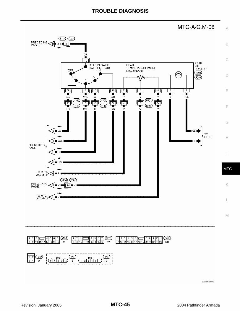
Schematic EJS0027W
WJWA0151E

MTC-38
TROUBLE DIAGNOSIS
Revision: January 2005 2004 Pathfinder Armada
Wiring Diagram — A/C,M — EJS0027X
WJWA0152E

TROUBLE DIAGNOSIS
MTC-39
C
D
E
F
G
H
I
K
L
M
A
B
MTC
Revision: January 2005 2004 Pathfinder Armada
WJWA0153E

MTC-40
TROUBLE DIAGNOSIS
Revision: January 2005 2004 Pathfinder Armada
WJWA0154E

TROUBLE DIAGNOSIS
MTC-41
C
D
E
F
G
H
I
K
L
M
A
B
MTC
Revision: January 2005 2004 Pathfinder Armada
WJWA0099E

MTC-42
TROUBLE DIAGNOSIS
Revision: January 2005 2004 Pathfinder Armada
WJWA0155E

TROUBLE DIAGNOSIS
MTC-43
C
D
E
F
G
H
I
K
L
M
A
B
MTC
Revision: January 2005 2004 Pathfinder Armada
WJWA0156E

MTC-44
TROUBLE DIAGNOSIS
Revision: January 2005 2004 Pathfinder Armada
WJWA0157E
TROUBLE DIAGNOSIS
MTC-45
C
D
E
F
G
H
I
K
L
M
A
B
MTC
Revision: January 2005 2004 Pathfinder Armada
WJWA0158E

MTC-46
TROUBLE DIAGNOSIS
Revision: January 2005 2004 Pathfinder Armada
WJWA0159E

TROUBLE DIAGNOSIS
MTC-47
C
D
E
F
G
H
I
K
L
M
A
B
MTC
Revision: January 2005 2004 Pathfinder Armada
Front Air Control Terminals and Reference Value EJS0027Y
Measure voltage between each terminal and ground by followingTerminals and Reference Value for front air control.
PIN CONNECTOR TERMINAL LAYOUT
TERMINALS AND REFERENCE VALUE FOR FRONT AIR CONTROL
WJIA0544E
WJIA0402E
Termi-nal No.
Wire color
ItemIgnition switch
ConditionVoltage (V)(Approx.)
1 B Ground - - 0V
2 Y Sensor power ON - 5V
3 W/G Air mix door motor (Front) CW ON Clockwise rotation Battery voltage
4 G Air mix door motor (Front) CCW ON Counterclockwise rotation Battery voltage
5 BR/W Mode door motor CW ON Clockwise rotation Battery voltage
6 P/L Mode door motor CCW ON Counterclockwise rotation Battery voltage
7 O Intake door motor CCW ON Counterclockwise rotation Battery voltage
8 G/B Intake door motor CW ON Clockwise rotation Battery voltage
9 L/B Intake sensor ON - 0 - 5V
10 W/G Water valveON Water valve open 0V
ON Water valve closed 5V
11 Y/B Rear defroster request ON - Battery voltage
12 W/R Compressor ON signalON A/C switch OFF 5V
ON A/C switch ON 0V
14 Y/G Power supply for IGN ON - Battery voltage
15 P Sensor ground ON - 0V
16 GR Mode door motor feedback ON - 0 - 5V
18 SB Air mix door motor (Front) feedback ON - 0 - 5V
19 LG Defroster door motor CW ON Clockwise rotation Battery voltage
20 P/B Defroster door motor CCW ON Counterclockwise rotation Battery voltage
21 V/R Sensor return ON - 0 - 5V
22 Y/R Power supply for BAT - - Battery voltage
23 R/L Illumination + ON Park lamps ON Battery voltage

MTC-48
TROUBLE DIAGNOSIS
Revision: January 2005 2004 Pathfinder Armada
24 BR Illumination - - Park lamps ON
25 LG/B Defroster door motor feedback ON - 0 - 5V
26 R/B Front blower monitor ONFront blower motor OFF Battery voltage
Front blower motor ON 0V
27 GR/R Air mix door motor (Rear) CW ON Clockwise rotation Battery voltage
28 L/Y Air mix door motor (Rear) CCW ON Counterclockwise rotation Battery voltage
33 V Air mix door (Rear) set point ON - 0 - 5V
34 W CAN-H ON - 0 - 5V
35 R CAN-L ON - 0 - 5V
38 W/L Rear blower request ONRear blower motor OFF Battery voltage
Rear blower motor ON 0V
39 Y/B Rear select signal ON - 0V - Battery voltage
41 B/W Blower ground ONFront blower motor OFF Battery voltage
Front blower motor ON 0V
42 R/Y Air mix door motor (Rear) feedback ON - 0 - 5V
Termi-nal No.
Wire color
ItemIgnition switch
ConditionVoltage (V)(Approx.)
PIIA2344E

TROUBLE DIAGNOSIS
MTC-49
C
D
E
F
G
H
I
K
L
M
A
B
MTC
Revision: January 2005 2004 Pathfinder Armada
Operational Check (Front) EJS0028T
The purpose of the operational check is to confirm that the system operates properly.
CHECKING BLOWER1. Turn blower control switch clockwise. Blower should operate on
low speed. The blower symbol should have one blade lit (on dis-play).
2. Turn the blower control switch again, and continue checkingblower speed and blower symbol until all speeds are checked.
3. Leave blower on MAX speed. If NG, go to trouble diagnosis procedure for front blower motor cir-cuit. Refer to MTC-70, "Front Blower Motor Circuit" .If OK, continue with next check.
CHECKING DISCHARGE AIR1. Turn the mode switch.2. Each position indicator should change shape (on display, if
equipped).
3. Confirm that discharge air comes out according to the air distri-bution table.
Mode door position is checked in the next step.If NG, go to trouble diagnosis procedure for MTC-55, "Mode DoorMotor Circuit" .If OK, continue with next check.NOTE:Confirm that the compressor clutch is engaged (sound or visualinspection) and intake door position is at fresh when the DEF or D/Fis selected.
CHECKING RECIRCULATION1. Press recirculation ( ) switch one time. Recirculation indica-
tor should illuminate.
2. Press recirculation ( ) switch one more time. Recirculationindicator should go off.
3. Listen for intake door position change (blower sound shouldchange slightly).
If NG, go to trouble diagnosis procedure for MTC-64, "Intake DoorMotor Circuit" .If OK, continue with next check.NOTE:Confirm that the compressor clutch is engaged (sound or visualinspection) and intake door position is at fresh when the DEF or D/F is selected.
Conditions : Engine running and at normal operating temperature
WJIA0487E
WJIA0488E
WJIA0528E
WJIA0489E
MTC-50
TROUBLE DIAGNOSIS
Revision: January 2005 2004 Pathfinder Armada
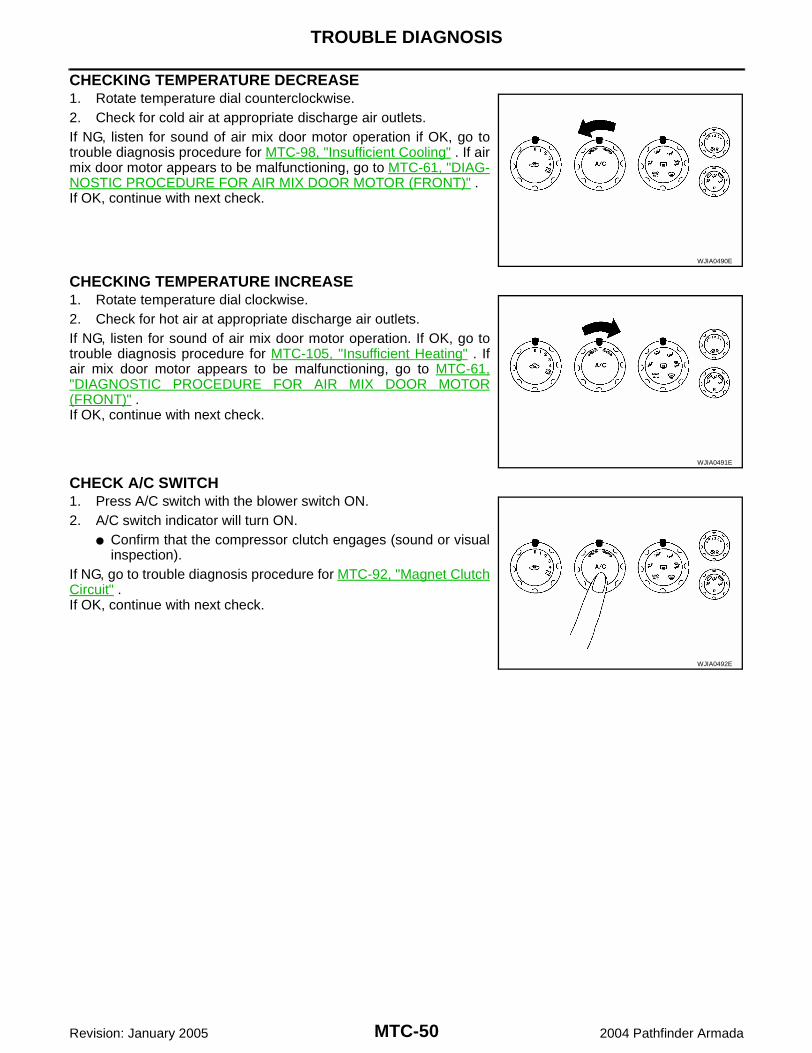
CHECKING TEMPERATURE DECREASE1. Rotate temperature dial counterclockwise.2. Check for cold air at appropriate discharge air outlets.If NG, listen for sound of air mix door motor operation if OK, go totrouble diagnosis procedure for MTC-98, "Insufficient Cooling" . If airmix door motor appears to be malfunctioning, go to MTC-61, "DIAG-NOSTIC PROCEDURE FOR AIR MIX DOOR MOTOR (FRONT)" .If OK, continue with next check.
CHECKING TEMPERATURE INCREASE1. Rotate temperature dial clockwise.2. Check for hot air at appropriate discharge air outlets.If NG, listen for sound of air mix door motor operation. If OK, go totrouble diagnosis procedure for MTC-105, "Insufficient Heating" . Ifair mix door motor appears to be malfunctioning, go to MTC-61,"DIAGNOSTIC PROCEDURE FOR AIR MIX DOOR MOTOR(FRONT)" .If OK, continue with next check.
CHECK A/C SWITCH1. Press A/C switch with the blower switch ON.2. A/C switch indicator will turn ON.
Confirm that the compressor clutch engages (sound or visualinspection).
If NG, go to trouble diagnosis procedure for MTC-92, "Magnet ClutchCircuit" .If OK, continue with next check.
WJIA0490E
WJIA0491E
WJIA0492E

TROUBLE DIAGNOSIS
MTC-51
C
D
E
F
G
H
I
K
L
M
A
B
MTC
Revision: January 2005 2004 Pathfinder Armada
Operational Check (Rear) EJS00281
The purpose of the operational check is to confirm that the system operates properly.
CHECKING BLOWER1. Turn the blower control switch clockwise to position "1". Blower
should operate on low speed.2. Turn the blower control switch clockwise again to switch position
"2", "3", and "4" until all speeds are checked.3. Leave blower on maximum speed. If NG, go to trouble diagnosis procedure for MTC-78, "Rear BlowerMotor Circuit" .If OK, continue with next check.
CHECKING TEMPERATURE DECREASE1. Rotate temperature/mode dial fully counterclockwise.2. Check for cold air at appropriate discharge air outlets.If NG, listen for sound of air mix door motor operation if OK, go totrouble diagnosis procedure for MTC-98, "Insufficient Cooling" . If airmix door motor appears to be malfunctioning, go to MTC-62, "DIAG-NOSTIC PROCEDURE FOR AIR MIX DOOR MOTOR (REAR)" .If OK, continue with next check.
CHECKING TEMPERATURE INCREASE1. Rotate temperature/mode dial clockwise.2. Check for hot air at appropriate discharge air outlets.If NG, listen for sound of air mix door motor operation. If OK, go totrouble diagnosis procedure for MTC-105, "Insufficient Heating" . Ifair mix door motor appears to be malfunctioning, go to MTC-61,"DIAGNOSTIC PROCEDURE FOR AIR MIX DOOR MOTOR(FRONT)" .If OK, continue with next check.
Conditions : Engine running and at normal operating temperature
WJIA1585E
WJIA1586E
WJIA1587E

MTC-52
TROUBLE DIAGNOSIS
Revision: January 2005 2004 Pathfinder Armada
Power Supply and Ground Circuit for Front Air Control EJS00282
SYMPTOM: A/C system does not come on.
INSPECTION FLOW
*1 MTC-52, "Power Supply and Ground Circuit for Front Air Control".
*2 MTC-49, "Operational Check (Front)" or MTC-51, "Operational Check (Rear)" .
*3 MTC-112, "FRONT AIR CONTROL"
WJIA1589E

TROUBLE DIAGNOSIS
MTC-53
C
D
E
F
G
H
I
K
L
M
A
B
MTC
Revision: January 2005 2004 Pathfinder Armada
COMPONENT DESCRIPTIONFront Air ControlThe front air control has a built-in microcomputer which processesinformation sent from various sensors needed for air conditioneroperation. The air mix door motors, mode door motor, intake doormotors, defroster door motor, blower motor and compressor are thencontrolled.The front air control is unitized with control mechanisms. When thevarious switches and temperature dials are operated, data is input tothe front air control.
Potentio Temperature Control (PTC)The PTC is built into the front air control. It can be set from cold tohot or any intermediate position by rotating the temperature dial.
DIAGNOSTIC PROCEDURE FOR A/C SYSTEMSYMPTOM: A/C system does not come on.
WJIA0544E
WJIA0494E
WJIA0414E

MTC-54
TROUBLE DIAGNOSIS
Revision: January 2005 2004 Pathfinder Armada
1. CHECK POWER SUPPLY CIRCUITS FOR FRONT AIR CONTROL
1. Disconnect front air control connector.2. Check voltage between front air control harness connector M49
terminals 14 (G/Y) and 22 (Y/R), and ground.
OK or NGOK >> GO TO 2.NG >> Check 10A fuses [Nos. 8 and 19, located in the fuse block (J/B)]. Refer to PG-74 .
If fuses are OK, check harness for open circuit. Repair or replace as necessary. If fuses are NG, replace fuse and check harness for short circuit. Repair or replace as neces-
sary.
2. CHECK GROUND CIRCUIT FOR FRONT AIR CONTROL
1. Turn ignition switch OFF.2. Check continuity between front air control harness connector
M49 terminal 1 (B) and ground.
OK or NGOK >> Replace front air control. Refer to MTC-112, "FRONT
AIR CONTROL" .NG >> Repair harness or connector.
Terminals Ignition switch position
(+)
(-) OFF ACC ONFront air control
connector
Terminal No.(Wire color)
M49 14 (Y/G)
Ground
Approx. 0V Approx. 0VBattery voltage
M49 22 (Y/R)Battery voltage
Battery voltage
Battery voltage
WJIA0415E
1 - Ground : Continuity should exist.
WJIA1588E

TROUBLE DIAGNOSIS
MTC-55
C
D
E
F
G
H
I
K
L
M
A
B
MTC
Revision: January 2005 2004 Pathfinder Armada
Mode Door Motor Circuit EJS00283
SYMPTOM: Air outlet does not change. Mode door motor does not operate normally.
INSPECTION FLOW
*1 MTC-27, "Discharge Air Flow". *2 MTC-49, "Operational Check (Front)".
*3 MTC-57, "DIAGNOSTIC PROCE-DURE FOR MODE DOOR MOTOR".
*4 MTC-33, "SYMPTOM TABLE". *5 MTC-112, "FRONT AIR CON-TROL".
WJIA1590E

MTC-56
TROUBLE DIAGNOSIS
Revision: January 2005 2004 Pathfinder Armada
SYSTEM DESCRIPTIONComponent PartsMode door control system components are: Front air control Mode door motor PBR (built into mode door motor)
System OperationThe mode door position (vent, B/L, foot, and defrost) is set by the front air control by means of the mode doormotor. When a mode door position is selected on the front air control, voltage is applied to one circuit of themode door motor while ground is applied to the other circuit, causing the mode door motor to rotate. The direc-tion of rotation is determined by which circuit has voltage applied to it, and which one has ground applied to it.The front air control monitors the mode door position by measuring the voltage signal on the PBR circuit.
Mode Door Control Specification
COMPONENT DESCRIPTIONMode Door MotorThe mode door motor is attached to the heater & cooling unit. Itrotates so that air is discharged from the outlet as indicated by thefront air control. Motor rotation is conveyed to a link which activatesthe mode door.
WJIA0434E
WJIA0587E
TROUBLE DIAGNOSIS
MTC-57
C
D
E
F
G
H
I
K
L
M
A
B
MTC
Revision: January 2005 2004 Pathfinder Armada
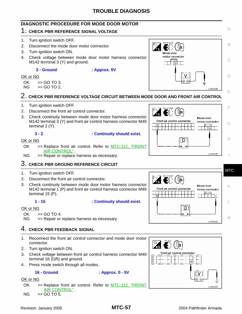
DIAGNOSTIC PROCEDURE FOR MODE DOOR MOTOR
1. CHECK PBR REFERENCE SIGNAL VOLTAGE
1. Turn ignition switch OFF.2. Disconnect the mode door motor connector.3. Turn ignition switch ON.4. Check voltage between mode door motor harness connector
M142 terminal 3 (Y) and ground.
OK or NGOK >> GO TO 3.NG >> GO TO 2.
2. CHECK PBR REFERENCE VOLTAGE CIRCUIT BETWEEN MODE DOOR AND FRONT AIR CONTROL
1. Turn ignition switch OFF.2. Disconnect the front air control connector.3. Check continuity between mode door motor harness connector
M142 terminal 3 (Y) and front air control harness connector M49terminal 2 (Y).
OK or NGOK >> Replace front air control. Refer to MTC-112, "FRONT
AIR CONTROL" .NG >> Repair or replace harness as necessary.
3. CHECK PBR GROUND REFERENCE CIRCUIT
1. Turn ignition switch OFF.2. Disconnect the front air control connector.3. Check continuity between mode door motor harness connector
M142 terminal 1 (P) and front air control harness connector M49terminal 15 (P).
OK or NGOK >> GO TO 4.NG >> Repair or replace harness as necessary.
4. CHECK PBR FEEDBACK SIGNAL
1. Reconnect the front air control connector and mode door motorconnector.
2. Turn ignition switch ON.3. Check voltage between front air control harness connector M49
terminal 16 (GR) and ground.4. Press mode switch through all modes.
OK or NGOK >> Replace front air control. Refer to MTC-112, "FRONT
AIR CONTROL" .NG >> GO TO 5.
3 - Ground : Approx. 5V
LJIA0028E
3 - 2 : Continuity should exist.
LJIA0029E
1 - 15 : Continuity should exist.
LJIA0031E
16 - Ground : Approx. 0 - 5V
LJIA0032E

MTC-58
TROUBLE DIAGNOSIS
Revision: January 2005 2004 Pathfinder Armada
5. CHECK PBR FEEDBACK CIRCUIT
1. Turn ignition switch OFF.2. Disconnect the mode door motor connector and front air control
harness connector.3. Check continuity between mode door motor harness connector
M142 terminal 2 (GR) and front air control harness connectorM49 terminal 16 (GR).
OK or NGOK >> Replace mode door motor. Refer to MTC-126, "MODE
DOOR MOTOR" .NG >> Repair or replace harness as necessary.
2 - 16 : Continuity should exist.
LJIA0034E
TROUBLE DIAGNOSIS
MTC-59
C
D
E
F
G
H
I
K
L
M
A
B
MTC
Revision: January 2005 2004 Pathfinder Armada
Air Mix Door Motor Circuit EJS00284
SYMPTOM: Discharge air temperature does not change. Air mix door motor does not operate.
INSPECTION FLOW
*1 MTC-49, "Operational Check (Front)" or MTC-51, "Operational Check (Rear)" .
*2 MTC-61, "DIAGNOSTIC PROCE-DURE FOR AIR MIX DOOR MOTOR (FRONT)".
*3 MTC-112, "FRONT AIR CON-TROL".
WJIA1591E

MTC-60
TROUBLE DIAGNOSIS
Revision: January 2005 2004 Pathfinder Armada
SYSTEM DESCRIPTIONComponent PartsAir mix door control system components are: Front air control Air mix door motors (Front and rear) PBR (built-into air mix motors)
System OperationThe front air control receives data from the temperature selected by the driver and rear passenger. The frontair control then applies a voltage to one circuit of the appropriate air mix door motor, while ground is applied tothe other circuit, causing the appropriate air mix door motor to rotate. The direction of rotation is determined bywhich circuit has voltage applied to it, and which one has ground applied to it. The front air control monitors theair mix door positions by measuring the voltage signal on the PBR circuits of each door.
Air Mix Door Control Specification
COMPONENT DESCRIPTIONAir Mix Door Motors
The air mix door motor front is attached to the front heater & coolingunit. The rear air mix door motor is attached to the rear heater &cooling unit. These motors rotate so that the air mix door is openedor closed to a position set by the front (or rear) air control. Motorrotation is then conveyed through a shaft and the air mix door posi-tion is then fed back to the front air control by the PBR built into theair mix door motors.
WJIA0435E
WJIA0641E
WJIA0430E

TROUBLE DIAGNOSIS
MTC-61
C
D
E
F
G
H
I
K
L
M
A
B
MTC
Revision: January 2005 2004 Pathfinder Armada
DIAGNOSTIC PROCEDURE FOR AIR MIX DOOR MOTOR (FRONT)
1. CHECK PBR REFERENCE SIGNAL VOLTAGE
1. Turn ignition switch OFF.2. Disconnect the air mix door motor (Front) connector.3. Turn ignition switch ON.4. Check voltage between air mix door motor (Front) harness con-
nector M147 terminal 3 (Y) and ground.
OK or NGOK >> GO TO 3.NG >> GO TO 2.
2. CHECK PBR REFERENCE VOLTAGE CIRCUIT BETWEEN AIR MIX DOOR MOTOR (FRONT) AND FRONT AIR CONTROL
1. Turn ignition switch OFF.2. Disconnect the front air control connector.3. Check continuity between air mix door motor (Front) harness
connector M147 terminal 3 (Y) and front air control harness con-nector M49 terminal 2 (Y).
OK or NGOK >> Replace front air control. Refer to MTC-112, "FRONT
AIR CONTROL" .NG >> Repair or replace harness as necessary.
3. CHECK PBR GROUND REFERENCE CIRCUIT
1. Turn ignition switch OFF.2. Disconnect the front air control connector.3. Check continuity between air mix door motor (Front) harness
connector M147 terminal 2 (P) and front air control harness con-nector M49 terminal 15 (P).
OK or NGOK >> GO TO 4.NG >> Repair or replace harness as necessary.
3 - Ground : Approx. 5V
WJIA0643E
3 - 2 : Continuity should exist.
WJIA0644E
2 - 15 : Continuity should exist.
WJIA0645E

MTC-62
TROUBLE DIAGNOSIS
Revision: January 2005 2004 Pathfinder Armada
4. CHECK PBR FEEDBACK SIGNAL
1. Reconnect the front air control connector and air mix door motor(Front) connector.
2. Turn ignition switch ON.3. Check voltage between front air control harness connector M49
terminal 18 (SB) and ground.4. Rotate front temperature dial through complete range.
OK or NGOK >> Replace front air control. Refer to MTC-112, "FRONT
AIR CONTROL" .NG >> GO TO 5.
5. CHECK PBR FEEDBACK CIRCUIT
1. Turn ignition switch OFF.2. Disconnect the air mix door motor (Front) connector and front air
control connector.3. Check continuity between air mix door motor (Front) harness
connector M147 terminal 4 (SB) and front air control harnessconnector M49 terminal 18 (SB).
OK or NGOK >> Replace air mix door motor (Front). Refer to MTC-127,
"FRONT AIR MIX DOOR MOTOR" .NG >> Repair or replace harness as necessary.
DIAGNOSTIC PROCEDURE FOR AIR MIX DOOR MOTOR (REAR)
1. CHECK PBR REFERENCE SIGNAL VOLTAGE
1. Turn ignition switch OFF.2. Disconnect the air mix door motor (Rear) connector.3. Turn ignition switch ON.4. Check voltage between air mix door motor (Rear) harness con-
nector B155 terminal 3 (Y) and ground.
OK or NGOK >> GO TO 3.NG >> GO TO 2.
18 - Ground : Approx. 0V - 5V
LJIA0041E
4 - 18 Continuity should exist.
WJIA0646E
3 - Ground : Approx. 5V
LJIA0050E

TROUBLE DIAGNOSIS
MTC-63
C
D
E
F
G
H
I
K
L
M
A
B
MTC
Revision: January 2005 2004 Pathfinder Armada
2. CHECK PBR REFERENCE VOLTAGE CIRCUIT BETWEEN AIR MIX DOOR MOTOR (REAR) AND FRONT AIR CONTROL
1. Turn ignition switch OFF.2. Disconnect the front air control connector.3. Check continuity between air mix door motor (Rear) harness
connector B155 terminal 3 (Y) and front air control harness con-nector M49 terminal 2 (Y).
OK or NGOK >> Replace front air control. Refer to MTC-112, "FRONT
AIR CONTROL" .NG >> Repair or replace harness as necessary.
3. CHECK PBR GROUND REFERENCE CIRCUIT
1. Turn ignition switch OFF.2. Disconnect the front air control connector.3. Check continuity between air mix door motor (Rear) harness
connector B155 terminal 2 (P) and front air control harness con-nector M49 terminal 15 (P).
OK or NGOK >> GO TO 4.NG >> Repair or replace harness as necessary.
4. CHECK PBR FEEDBACK SIGNAL
1. Reconnect the front air control connector and air mix door motor(Rear) connector.
2. Turn ignition switch ON.3. Check voltage between front air control harness connector M50
terminal 42 (R/Y) and ground.4. Rotate rear temperature dial through complete range.
OK or NGOK >> Replace front air control. Refer to MTC-112, "FRONT
AIR CONTROL" .NG >> GO TO 5.
5. CHECK PBR FEEDBACK CIRCUIT
1. Turn ignition switch OFF.2. Disconnect the air mix door motor (Rear) connector and front air
control connector.3. Check continuity between air mix door motor (Rear) harness
connector B155 terminal 4 (R/Y) and front air control harnessconnector M50 terminal 42 (R/Y).
OK or NGOK >> Replace air mix door motor (Rear) MTC-128, "REAR
AIR MIX DOOR MOTOR" .NG >> Repair or replace harness as necessary.
3 - 2 Continuity should exist.
LJIA0051E
2 - 15 Continuity should exist.
LJIA0052E
42 - Ground : Approx. 0 - 5V
LJIA0053E
4 - 42 Continuity should exist.
LJIA0054E

MTC-64
TROUBLE DIAGNOSIS
Revision: January 2005 2004 Pathfinder Armada
Intake Door Motor Circuit EJS00285
SYMPTOM: Intake door does not change. Intake door motor does not operate normally.
INSPECTION FLOW
*1 MTC-49, "Operational Check (Front)".
*2 MTC-112, "FRONT AIR CON-TROL".
WJIA1592E

TROUBLE DIAGNOSIS
MTC-65
C
D
E
F
G
H
I
K
L
M
A
B
MTC
Revision: January 2005 2004 Pathfinder Armada
SYSTEM DESCRIPTIONComponent PartsIntake door control system components are: Front air control Intake door motor
System OperationThe intake door control determines the intake door position based on the position of the recirculation switch.When the recirculation switch is depressed the intake door motor rotate closing off the fresh air inlet and recir-culating the cabin air. If the recirculation switch is depressed again, the intake door motor rotate in the oppo-site direction, again allowing fresh air into the cabin.
Intake Door Control Specification
COMPONENT DESCRIPTIONIntake door motor
The intake door motor is attached to the intake unit. It rotates so that air is drawn from inlets set by the front aircontrol. Motor rotation is conveyed to a lever which activates the intake door.
WJIA0436E
WJIA0552E

MTC-66
TROUBLE DIAGNOSIS
Revision: January 2005 2004 Pathfinder Armada
DIAGNOSTIC PROCEDURE FOR INTAKE DOOR MOTOR
1. CHECK INTAKE DOOR MOTOR CIRCUIT VOLTAGE
1. Turn ignition switch OFF.2. Disconnect intake door motor connector.3. Turn ignition switch ON.4. Rotate the temperature control dial clockwise.5. Check voltage between intake door motor harness connector
M58 terminal 6 (G/B) and ground.
OK or NGOK >> GO TO 3.NG >> GO TO 2.
2. CHECK INTAKE DOOR MOTOR CIRCUIT FOR OPEN
1. Turn ignition switch OFF.2. Disconnect front air control connector.3. Check continuity between front air control harness connector
M49 terminal 8 (G/B) and intake door motor harness connectorM58 terminal 6 (G/B).
OK or NGOK >> Replace front air control connector. Refer to MTC-112,
"FRONT AIR CONTROL" .NG >> Repair or replace harness as necessary.
3. CHECK INTAKE DOOR MOTOR CIRCUIT VOLTAGE
1. Turn ignition switch ON.2. Rotate the temperature control dial counterclockwise.3. Check voltage between intake door motor harness connector
M58 terminal 1 and ground.
OK or NGOK >> Replace intake door motor. Refer to MTC-125, "INTAKE
DOOR MOTOR" .NG >> GO TO 4.
4. CHECK INTAKE DOOR MOTOR CIRCUIT FOR OPEN
1. Turn ignition switch OFF.2. Disconnect front air control connector.3. Check continuity between front air control harness connector
M49 terminal 7 (O) and intake door motor harness connectorM58 terminal 1 (O).
OK or NGOK >> Replace front air control. Refer to MTC-112, "FRONT
AIR CONTROL" .NG >> Repair or replace harness as necessary.
6 - Ground :Battery voltage
WJIA1324E
8 - 6 :Continuity should exist.
WJIA1593E
1 - Ground :Battery voltage
WJIA1326E
7 - 1 :Continuity should exist.
WJIA1594E

TROUBLE DIAGNOSIS
MTC-67
C
D
E
F
G
H
I
K
L
M
A
B
MTC
Revision: January 2005 2004 Pathfinder Armada
Defroster Door Motor Circuit EJS00286
SYMPTOM: Defroster door does not change. Defroster door does not operate normally.
INSPECTION FLOW
*1MTC-49, "Operational Check (Front)"
*2 MTC-112, "FRONT AIR CONTROL"
WJIA1595E

MTC-68
TROUBLE DIAGNOSIS
Revision: January 2005 2004 Pathfinder Armada
SYSTEM DESCRIPTIONComponent PartsDefroster door control system components are: Front air control Defroster door motor PBR (built into defroster door motor)
System OperationThe front air control determines defroster door position based on the position of the mode switch. When themode switch is in the defroster position, the defroster door motor rotates directing air to the defroster ducts.When any mode other than defroster is selected, the defroster motor rotates in the opposite direction closingoff air flow to the defroster ducts. The front air control monitors the position of the defroster door position bymeasuring the voltage on the PBR circuit.
COMPONENT DESCRIPTIONDefroster door motor The defroster door motor is attached to the front heater & coolingunit. The front air control sends a voltage to rotate to the defrosterdoor directing the air flow either to the defroster ducts, or to the floorducts, depending on which way the voltage and ground are appliedto the motor leads. Motor rotation is conveyed to a lever which acti-vates the defroster door.
DIAGNOSTIC PROCEDURE FOR DEFROSTER DOOR MOTOR
1. CHECK PBR REFERENCE SIGNAL VOLTAGE
1. Turn ignition switch OFF.2. Disconnect the defroster door motor harness connector.3. Turn ignition switch ON.4. Check voltage between defroster door motor harness connector
M144 terminal 3 (Y) and ground.
OK or NGOK >> GO TO 3.NG >> GO TO 2.
2. CHECK PBR REFERENCE VOLTAGE CIRCUIT BETWEEN DEFROSTER DOOR MOTOR AND FRONT AIR CONTROL
1. Turn ignition switch OFF.2. Disconnect the front air control connector.3. Check continuity between defroster door motor harness connec-
tor M144 terminal 3 (Y) and front air control harness connectorM49 terminal 2 (Y).
OK or NGOK >> Replace front air control. Refer to MTC-112, "FRONT
AIR CONTROL" .NG >> Repair or replace harness as necessary.
WJIA0592E
3 - Ground : Approx. 5V.
WJIA0554E
3 - 2 : Continuity should exist.
WJIA0555E

TROUBLE DIAGNOSIS
MTC-69
C
D
E
F
G
H
I
K
L
M
A
B
MTC
Revision: January 2005 2004 Pathfinder Armada
3. CHECK PBR GROUND REFERENCE CIRCUIT
1. Turn ignition switch OFF.2. Disconnect the front air control connector.3. Check continuity between defroster door motor harness connec-
tor M144 terminal 2 (P) and front air control harness connectorM49 terminal 15 (P).
OK or NGOK >> GO TO 4.NG >> Repair or replace harness as necessary.
4. CHECK PBR FEEDBACK SIGNAL
1. Reconnect the front air control connector and mode door motorconnector.
2. Turn ignition switch ON.3. Check voltage between front air control harness connector M49
terminal 25 (LG/B) and ground.4. Change mode between floor, defroster, and panel.
OK or NGOK >> Replace front air control. Refer to MTC-112, "FRONT
AIR CONTROL" .NG >> GO TO 5.
5. CHECK PBR FEEDBACK CIRCUIT
1. Turn ignition switch OFF.2. Disconnect the defroster door motor connector and front air con-
trol connector.3. Check continuity between defroster door motor harness connec-
tor M144 terminal 4 (LG/B) and front air control harness connec-tor M49 terminal 25 (LG/B).
OK or NGOK >> Replace defroster door motor. Refer to MTC-124,
"DEFROSTER DOOR MOTOR" .NG >> Repair or replace harness as necessary.
2 - 15 : Continuity should exist.
WJIA0556E
25 - Ground : Approx.0 - 5V
WJIA1596E
4 - 25 : Continuity should exist.
WJIA0558E

MTC-70
TROUBLE DIAGNOSIS
Revision: January 2005 2004 Pathfinder Armada
Front Blower Motor Circuit EJS00287
SYMPTOM: Blower motor operation is malfunctioning.
INSPECTION FLOW
*1 MTC-49, "Operational Check (Front)".
*2 MTC-72, "DIAGNOSTIC PROCE-DURE FOR BLOWER MOTOR".
*3 EC-163, "DTC P0117, P0118 ECT SENSOR".
*4 MTC-33, "SYMPTOM TABLE". *5 MTC-112, "FRONT AIR CONTROL"
WJIA1597E
TROUBLE DIAGNOSIS
MTC-71
C
D
E
F
G
H
I
K
L
M
A
B
MTC
Revision: January 2005 2004 Pathfinder Armada
SYSTEM DESCRIPTIONComponent Parts Front air control Front blower switch Front blower motor resistor Front blower motor Front blower motor relay
System Operation
Blower Speed Control Specification
COMPONENT DESCRIPTIONBlower Motor ResistorThe blower motor resistor is located on the cooling unit. The blowermotor resistor grounds the blower motor through a series of 1, 2, orthree resistors, depending upon speed selected. For high speedoperation the blower motor resistor is circumvented and the blowermotor grounds directly.
WJIA1005E
WJIA0441E
WJIA0648E

MTC-72
TROUBLE DIAGNOSIS
Revision: January 2005 2004 Pathfinder Armada
DIAGNOSTIC PROCEDURE FOR BLOWER MOTORSYMPTOM: Blower motor operation is malfunctioning.
1. DIAGNOSTIC PROCEDURE
Turn the front blower switch to each of its four speeds.Does blower motor rotate normally at each speed?YES or NOYES >> INSPECTION END.NO >> 1. Does not rotate at any speed, GO TO 2.
2. Does not rotate at 1 - 3 speed, GO TO 13.3. Does not rotate at 4 speed, GO TO 16.
2. CHECK FUSES
Check 20A fuses (Nos. 24 and 27, located in the fuse and fusible link box). Refer to PG-75, "FUSE AND FUS-IBLE LINK BOX" .OK or NGOK >> GO TO 3.NG >> GO TO 8.
3. CHECK FRONT BLOWER MOTOR POWER SUPPLY
1. Disconnect front blower motor harness connector.2. Select any front blower speed except OFF.3. Check voltage between front blower motor harness connector
M62 terminal 2 (W/L) and ground.
OK or NGOK >> GO TO 11.NG >> GO TO 4.
WJIA0502E
2 - Ground : Battery voltage
WJIA0650E

TROUBLE DIAGNOSIS
MTC-73
C
D
E
F
G
H
I
K
L
M
A
B
MTC
Revision: January 2005 2004 Pathfinder Armada
4. CHECK FRONT BLOWER MOTOR RELAY
Refer to MTC-76, "Front Blower Motor Relay" .OK or NGOK >> GO TO 5.NG >> Replace front blower motor relay.
5. CHECK FRONT BLOWER MOTOR POWER FROM RELAY TO FRONT BLOWER MOTOR
1. Reconnect front blower motor harness connector.2. Disconnect front blower motor relay.3. Connect a jumper wire between front blower motor relay con-
nector H2 (harness side) terminals 3 and 5 and between frontblower motor relay connector H2 (harness side) terminals 6 and7.
4. Momentarily (no more than 4 seconds), set front blower switchto any position except OFF.
OK or NGOK >> GO TO 6.NG >> GO TO 10.
6. CHECK FRONT BLOWER MOTOR RELAY (COIL SIDE) POWER SUPPLY CIRCUIT
1. Set front blower switch to any position except OFF.2. Check voltage between front blower motor relay harness con-
nector H2 terminal 1 (Y/G) and ground.
OK or NGOK >> GO TO 7.NG >> Repair harness or connector.
7. CHECK FRONT BLOWER MOTOR RELAY (COIL SIDE) GROUND CIRCUIT
1. Turn ignition switch OFF.2. Check continuity between front blower motor relay harness connector H2 terminal 2 (B) and ground.
OK or NGOK >> Replace front blower motor relay.NG >> Repair harness or connector.
Front blower motor should rotate.
WJIA0503E
1 - Ground : Battery voltage.
WJIA0504E
2 - Ground Continuity should exist.
WJIA0505E

MTC-74
TROUBLE DIAGNOSIS
Revision: January 2005 2004 Pathfinder Armada
8. REPLACE FUSE
Refer to PG-75, "FUSE AND FUSIBLE LINK BOX" .Does fuse open when front blower motor is turned on?YES or NOYES >> GO TO 9.NO >> INSPECTION END.
9. CHECK FRONT BLOWER MOTOR POWER SUPPLY CIRCUIT FOR SHORT
1. Turn ignition switch OFF.2. Disconnect front blower motor harness connector.3. Check continuity between front blower motor harness connector
M62 terminal 2 (W/L) and ground.
OK or NGOK >> Check front blower motor. Refer to MTC-76, "Front
Blower Motor" .NG >> Repair harness or connector.
10. CHECK FRONT BLOWER MOTOR RELAY (SWITCH SIDE) POWER SUPPLY CIRCUIT
1. Turn ignition switch OFF.2. Disconnect front blower motor harness connector.3. Check continuity between front blower motor relay harness con-
nector H2 terminal 5 (W/L) and 7 (W/L) and front blower motorharness connector M62 terminal 2 (W/L).
OK or NGOK >> Repair harness or connector between front blower
motor fuses and front blower motor relay.NG >> Repair harness or connector between front blower
motor relay and front blower motor.
11. CHECK FRONT BLOWER MOTOR
Refer to MTC-76, "Front Blower Motor" .OK or NGOK >> GO TO 12.NG >> Replace front blower motor.
12. CHECK FRONT BLOWER SWITCH
Refer to MTC-76, "Front Blower Switch" .OK or NGOK >> Repair harness or connector between front blower switch and front blower motor.NG >> Replace front air control. Refer to MTC-112, "FRONT AIR CONTROL" .
13. CHECK FRONT BLOWER MOTOR RESISTOR
Refer to MTC-77, "Front Blower Motor Resistor" .OK or NGOK >> GO TO 14.NG >> Replace front blower motor resistor. Refer to MTC-129, "Removal and Installation" .
2 - Ground : Continuity should not exist.
WJIA0649E
5, 7 - 2 : Continuity should exist.
WJIA0651E

TROUBLE DIAGNOSIS
MTC-75
C
D
E
F
G
H
I
K
L
M
A
B
MTC
Revision: January 2005 2004 Pathfinder Armada
14. CHECK FRONT BLOWER SWITCH CIRCUIT
1. Reconnect front blower motor resistor harness connector.2. Check voltage between front blower switch connector M51 ter-
minals 2 (R/B), 3 (L/R), and 7 (L/Y) and ground.
OK or NGOK >> Replace front air control. Refer to MTC-112, "FRONT AIR CONTROL" .NG >> GO TO 15.
15. CHECK FRONT BLOWER MOTOR GROUND CIRCUIT TO FRONT BLOWER MOTOR RESISTOR
1. Turn ignition switch OFF.2. Disconnect front blower motor and front blower motor resistor
harness connector.3. Check continuity between front blower motor connector M62 ter-
minal 1 (L/W) and front blower motor resistor harness connectorM122 terminal 3 (L/W).
4. Check continuity between front blower motor connector M62 ter-minal 1 (L/W) and ground.
OK or NGOK >> INSPECTION END.NG >> Repair harness or connector.
16. CHECK FRONT BLOWER SWITCH
Refer to MTC-76, "Front Blower Switch" .OK or NGOK >> Repair harness or connector.NG >> Replace front air control. Refer to MTC-112, "FRONT AIR CONTROL" .
Terminal No. Voltage (Approx.)+ -
2
Ground 12V3
7WJIA0510E
1 - 3 : Continuity should exist.
1 - Ground : Continuity should not exist.WJIA0647E
MTC-76
TROUBLE DIAGNOSIS
Revision: January 2005 2004 Pathfinder Armada
COMPONENT INSPECTIONFront Blower Motor RelayCheck continuity between terminals by supplying 12 volts andground to coil side terminals of relay.
Front Blower MotorConfirm smooth rotation of the blower motor. Ensure that there are no foreign particles inside the blower unit. Apply 12 volts to terminal 2 and ground to terminal 1 and verify
that the motor operates freely and quietly.
Front Blower SwitchCheck continuity between terminals at each switch position.
LJIA0068E
WJIA0595E
WJIA0508E

TROUBLE DIAGNOSIS
MTC-77
C
D
E
F
G
H
I
K
L
M
A
B
MTC
Revision: January 2005 2004 Pathfinder Armada
Front Blower Motor ResistorCheck continuity between terminals. There will be resistance, butthere should not be an open or short between any two terminals.
WJIA0509E

MTC-78
TROUBLE DIAGNOSIS
Revision: January 2005 2004 Pathfinder Armada
Rear Blower Motor Circuit EJS00288
SYMPTOM: Blower motor operation is malfunctioning.
INSPECTION FLOW
*1 MTC-49, "Operational Check (Front)" or MTC-51, "Operational Check (Rear)" .
*2 MTC-87, "Rear Blower Switch (Front)"
*3 MTC-33, "SYMPTOM TABLE"
WJIA0517E

TROUBLE DIAGNOSIS
MTC-79
C
D
E
F
G
H
I
K
L
M
A
B
MTC
Revision: January 2005 2004 Pathfinder Armada
SYSTEM DESCRIPTIONComponent PartsRear blower speed control system components are: Front air control Rear blower switch (front) Rear blower switch (rear) Rear blower motor resistor Rear blower motor Rear blower motor relay
System Operation
Rear Blower ControlWhen the rear blower switch (front) is in the OFF position, the rear blower motor cannot operate.When the rear blower switch (front) is in the REAR position, it allows the rear blower switch (rear) to controlthe rear blower motor speed. In any other position (1-4), the rear blower switch (front) controls the rear blowermotor speed regardless of the rear blower switch (rear) position.
DIAGNOSTIC PROCEDURE FOR REAR BLOWER MOTORRear Blower Switch (Rear) CircuitSYMPTOM: Rear blower motor does not rotate when rear blower switch (front) is set to REAR position.
1. CHECK REAR BLOWER MOTOR OPERATION
Blower motor rotates normally when rear blower switch (front) is set at 1 - 4 speed.OK or NGOK >> GO TO 2.NG >> Refer to MTC-81, "Trouble Diagnosis Procedure For Rear Blower Motor (1 - 4 Speed)" .
2. CHECK REAR BLOWER SWITCH (FRONT)
Refer to MTC-87, "Rear Blower Switch (Front)" .OK or NGOK >> GO TO 3.NG >> Replace rear blower switch (front).
WJIA1004E

MTC-80
TROUBLE DIAGNOSIS
Revision: January 2005 2004 Pathfinder Armada
3. CHECK REAR BLOWER SWITCH (REAR)
Refer to MTC-87, "Rear Blower Switch (Rear)" .OK or NGOK >> GO TO 4.NG >> Replace rear blower switch (rear). Refer to MTC-112, "REAR AIR CONTROL" .
4. CHECK CIRCUIT CONTINUITY
1. Turn ignition switch OFF.2. Disconnect rear blower switch (front) connector and rear blower
switch (rear) connector.3. Check continuity between rear blower switch (front) harness
connector M52 terminal 2 (BR) and rear blower switch (rear)harness connector R208 terminal 10 (BR).
OK or NGOK >> Inspection End.NG >> Repair harness or connector.
2 - 10 : Continuity should exist.
LJIA0098E

TROUBLE DIAGNOSIS
MTC-81
C
D
E
F
G
H
I
K
L
M
A
B
MTC
Revision: January 2005 2004 Pathfinder Armada
Trouble Diagnosis Procedure For Rear Blower Motor (1 - 4 Speed)SYMPTOM: Rear blower motor does not rotate when rear blower switch (front) is set at 1 - 4 speed.
Inspection Flow
*1 MTC-49, "Operational Check (Front)" or MTC-51, "Operational Check (Rear)" .
*2 MTC-81, "Trouble Diagnosis Proce-dure For Rear Blower Motor (1 - 4 Speed)".
*3 MTC-33, "SYMPTOM TABLE".
WJIA0518E

MTC-82
TROUBLE DIAGNOSIS
Revision: January 2005 2004 Pathfinder Armada
1. DIAGNOSTIC PROCEDURE
Blower motor rotates normally at each speed.OK or NGOK >> Inspection End.NG >> 1. Does not rotate at any speed, GO TO 2.
2. Does not rotate at 1 - 3 speed, GO TO 13.3. Does not rotate at 4 speed, GO TO 18.
2. CHECK FUSES
Check 15A fuses [Nos. 10 and 11, located in the fuse block (J/B)]. Refer to PG-74, "FUSE BLOCK-JUNCTIONBOX(J/B)" .OK or NGOK >> GO TO 3.NG >> GO TO 8.
3. CHECK REAR BLOWER MOTOR POWER SUPPLY
1. Turn ignition switch OFF.2. Disconnect rear blower motor connector.3. Select any rear blower speed except OFF.4. Turn ignition switch ON.5. Check voltage between rear blower motor harness connector
B134 terminal 2 (L/R) and ground.
OK or NGOK >> GO TO 11.NG >> GO TO 4.
4. CHECK REAR BLOWER MOTOR RELAY
Refer to MTC-87, "Rear Blower Motor Relay" .OK or NGOK >> GO TO 5.NG >> Replace rear blower motor relay.
5. CHECK REAR BLOWER MOTOR POWER FROM RELAY TO REAR BLOWER MOTOR
1. Turn ignition switch OFF.2. Reconnect rear blower motor connector.3. Disconnect rear blower motor relay J1.4. Turn ignition switch ON.5. Set rear blower switch (front) to any position except OFF, REAR,
or 4 - speed.6. Momentarily (no more than 4 seconds), connect a jumper wire
between rear blower motor relay connector J1 (harness side)terminals 3 and 5.
OK or NGOK >> GO TO 6.NG >> GO TO 10.
2 - Ground : Battery voltage.
WJIA0596E
Rear blower motor should rotate. LJIA0100E

TROUBLE DIAGNOSIS
MTC-83
C
D
E
F
G
H
I
K
L
M
A
B
MTC
Revision: January 2005 2004 Pathfinder Armada
6. CHECK REAR BLOWER MOTOR RELAY (COIL SIDE) POWER SUPPLY CIRCUIT
1. Turn ignition switch OFF.2. Disconnect fuse block (J/B) connector.3. Turn ignition switch ON.4. Set rear blower switch (front) to any position except OFF, REAR,
or 4 - speed.5. Check voltage between fuse block (J/B) harness connector M39
terminal 3Q (W/L) and ground.
OK or NGOK >> GO TO 7.NG >> GO TO 20.
7. CHECK REAR BLOWER MOTOR RELAY (COIL SIDE) GROUND CIRCUIT
1. Turn ignition switch OFF.2. Check continuity between fuse block (J/B) harness connector
M3 terminal 7N (B) and ground.
OK or NGOK >> Replace fuse block (J/B).NG >> Repair harness or connector.
8. REPLACE FUSE
Refer to PG-74, "FUSE BLOCK-JUNCTION BOX(J/B)"Fuse should not open when rear blower motor is activated.OK or NGOK >> Inspection End.NG >> GO TO 9.
9. CHECK REAR BLOWER MOTOR POWER SUPPLY CIRCUIT FOR SHORT
1. Turn ignition switch OFF.2. Disconnect battery cables and rear blower motor connector.3. Check continuity between rear blower motor harness connector
B134 terminal 2 (L/R) and ground.
OK or NGOK >> Check rear blower motor. Refer to MTC-88, "Rear
Blower Motor" .NG >> Repair harness or connector.
3Q - Ground : Battery voltage.
LJIA0101E
7N - Ground : Continuity should exist.
WJIA0597E
2 - Ground : Continuity should not exist.
WJIA0598E

MTC-84
TROUBLE DIAGNOSIS
Revision: January 2005 2004 Pathfinder Armada
10. CHECK REAR BLOWER MOTOR RELAY (SWITCH SIDE) POWER SUPPLY CIRCUIT
1. Turn ignition switch OFF.2. Disconnect fuse block (J/B) and rear blower motor connectors.3. Check continuity between fuse block (J/B) harness connector
M3 terminal 3N (SB) and 8N (L/R) and rear blower motor har-ness connector B134 terminal 2 (L/R).
OK or NGOK >> GO TO 20.NG >> Repair harness or connector.
11. CHECK REAR BLOWER MOTOR
Refer to MTC-88, "Rear Blower Motor" .OK or NGOK >> GO TO 12.NG >> Replace rear blower motor. refer to MTC-115, "REAR BLOWER MOTOR"
12. CHECK REAR BLOWER SWITCH (FRONT)
Refer to MTC-87, "Rear Blower Switch (Front)" .OK or NGOK >> GO TO 15.NG >> Replace rear blower switch (front).
13. CHECK REAR BLOWER MOTOR RESISTOR
Refer to MTC-88, "Rear Blower Motor Resistor" .OK or NGOK >> GO TO 14.NG >> Replace rear blower motor resistor.
14. CHECK REAR BLOWER SWITCH (FRONT) CIRCUIT
1. Turn ignition switch OFF.2. Disconnect rear blower switch (front) M52.3. Turn ignition switch ON.4. Reconnect rear blower motor resistor harness connector B133.5. Check voltage between each rear blower switch (front) connec-
tor M52 terminals 3 (LG), 7 (W/L), and 8 (G), and ground.
OK or NGOK >> GO TO 17.NG >> GO TO 16.
3N, 8N - 2 : Continuity should exist.
WJIA0599E
Terminal No.Voltage
(+) (-)
3
Ground Approx. 12V7
8
LJIA0108E
TROUBLE DIAGNOSIS
MTC-85
C
D
E
F
G
H
I
K
L
M
A
B
MTC
Revision: January 2005 2004 Pathfinder Armada
15. CHECK REAR BLOWER MOTOR GROUND CIRCUIT TO REAR BLOWER MOTOR RESISTOR
1. Turn ignition switch OFF.2. Disconnect rear blower motor and rear blower motor resistor
connectors.3. Check continuity between rear blower motor connector B134
terminal 1 (L/B) and rear blower motor resistor harness connec-tor B133 terminal 3 (L/B).
4. Check continuity between rear blower motor connector B134terminal 1 (L/B) and ground.
OK or NGOK >> GO TO 16.NG >> Repair harness or connector.
16. CHECK REAR BLOWER SWITCH (FRONT) CIRCUIT
1. Turn ignition switch OFF.2. Disconnect rear blower motor resistor connector.3. Check continuity between rear blower switch (front) connector
M52 terminals 3 (LG), 7 (W/L), and 8 (G), and rear blower motorresistor connector B133 terminals 1 (LG), 4 (W/L), and 2 (G).
OK or NGOK >> Inspection End.NG >> Repair harness or connector.
17. CHECK REAR BLOWER SWITCH (FRONT) CIRCUIT
1. Turn ignition switch OFF.2. Disconnect rear blower switch (rear) connectors.3. Check continuity between rear blower switch (front) connector
M52 terminals 3 (LG), 5 (L/B), 7 (W/L), and 8 (G), and rearblower switch (rear) connector R203 terminals 9 (LG), 6 (L/B), 8(W/L), and 7 (G).
OK or NGOK >> GO TO 18.NG >> Repair harness or connector.
1 - 3 : Continuity should exist.
1 - Ground : Continuity should not exist.WJIA0600E
Terminal No.Continuity
Rear blower switch (front) Rear blower motor resistor
3 1
Should exist7 4
8 2
LJIA0109E
Terminal No.Continuity
Rear blower switch (front) Rear blower switch (rear)
3 9
Should exist5 6
7 8
8 7
LJIA0110E

MTC-86
TROUBLE DIAGNOSIS
Revision: January 2005 2004 Pathfinder Armada
18. CHECK REAR BLOWER SWITCH (FRONT)
Refer to MTC-87, "Rear Blower Switch (Front)" .OK or NGOK >> GO TO 19.NG >> Replace rear blower switch (front).
19. CHECK REAR BLOWER SWITCH (REAR)
Refer to MTC-87, "Rear Blower Switch (Rear)" .OK or NGOK >> Inspection End.NG >> Replace rear blower switch (rear).
20. CHECK CIRCUIT BETWEEN FRONT AIR CONTROL AND FUSE BLOCK (J/B) [REAR BLOWER MOTOR RELAY (COIL SIDE) POWER]
1. Disconnect front air control and fuse block (J/B) connectorsM39.
2. Check continuity between front air control harness connectorM50 terminal 38 (W/L) and fuse block (J/B) connector M39 ter-minal 3Q (W/L).
OK or NGOK >> Replace front air control.NG >> Repair harness or connector.
Continuity should exist.
LJIA0111E

TROUBLE DIAGNOSIS
MTC-87
C
D
E
F
G
H
I
K
L
M
A
B
MTC
Revision: January 2005 2004 Pathfinder Armada
COMPONENT INSPECTIONRear Blower Motor RelayCheck circuit continuity between terminals by supplying 12 volts andground to coil side terminals of relays.
Rear Blower Switch (Rear)Check continuity between terminals at each switch position.
Rear Blower Switch (Front)Check continuity between terminals at each switch position.
LJIA0068E
LJIA0113E
LJIA0114E

MTC-88
TROUBLE DIAGNOSIS
Revision: January 2005 2004 Pathfinder Armada
Rear Blower MotorCheck that there are no foreign particles inside the intake unit.Apply 12 volts to terminal 2 and ground to terminal 1 and ensure thatthe blower motor rotates freely and quietly.
Rear Blower Motor ResistorCheck continuity between terminals. There will be resistance, butthere should not be an open or short between any two terminals.
WJIA0601E
LJIA0116E
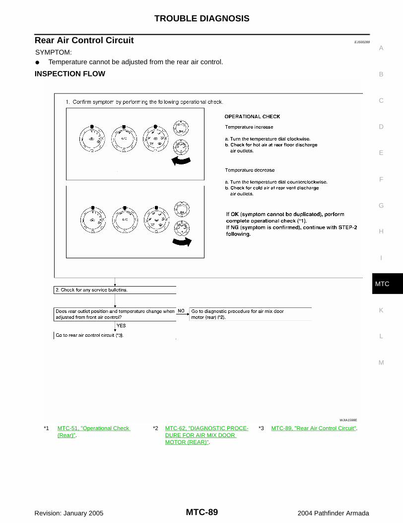
TROUBLE DIAGNOSIS
MTC-89
C
D
E
F
G
H
I
K
L
M
A
B
MTC
Revision: January 2005 2004 Pathfinder Armada
Rear Air Control Circuit EJS00289
SYMPTOM: Temperature cannot be adjusted from the rear air control.
INSPECTION FLOW
*1 MTC-51, "Operational Check (Rear)".
*2 MTC-62, "DIAGNOSTIC PROCE-DURE FOR AIR MIX DOOR MOTOR (REAR)".
*3 MTC-89, "Rear Air Control Circuit".
WJIA1598E

MTC-90
TROUBLE DIAGNOSIS
Revision: January 2005 2004 Pathfinder Armada
SYSTEM DESCRIPTIONComponent PartsRear air control system components are: Front air control Rear air control Air mix motor (rear) Rear blower relay Rear blower motor resistor Rear blower motor
System Operation
Rear Air ControlWhen the rear blower switch (front) (integral to the front air control) is in the REAR position the rear blowermotor speeds and the rear temperature/mode are controlled by the rear blower switch (rear) and the rear tem-perature switch (rear) (both integral to the rear air control).
DIAGNOSTIC PROCEDURE FOR REAR AIR CONTROLSYMPTOM: Blower motor operation is malfunctioning. Refer to MTC-78, "Rear Blower Motor Circuit" . Temperature/mode operation is malfunctioning.
1. CHECK OPERATION FROM FRONT AIR CONTROL
Does rear temperature/mode operate normally from front air control?YES or NOYES >> GO TO 2.NO >> Refer to MTC-62, "DIAGNOSTIC PROCEDURE FOR AIR MIX DOOR MOTOR (REAR)" .
LJIA0120E

TROUBLE DIAGNOSIS
MTC-91
C
D
E
F
G
H
I
K
L
M
A
B
MTC
Revision: January 2005 2004 Pathfinder Armada
2. CHECK CIRCUIT BETWEEN REAR AIR CONTROL AND FRONT AIR CONTROL FOR OPEN AND SHORT
1. Turn ignition switch OFF.2. Disconnect front air control and rear air control connectors.3. Check continuity between front air control harness connector
M50 terminal 33 (V) and rear air control harness connectorR204 terminal 5 (V).
4. Check continuity between rear air control harness connectorR204 terminal 5 (V) and ground.
OK or NGOK >> GO TO 3.NG >> Repair harness or connector.
3. CHECK CIRCUIT BETWEEN REAR AIR CONTROL AND AIR MIX DOOR MOTOR (REAR) FOR OPEN OR SHORT
1. Disconnect air mix door motor (rear) connector.2. Check continuity between rear air control harness connector
R204 terminal 2 (P) and 4 (Y) and air mix door motor (rear) har-ness connector B155 terminal 2 (P) and 3 (Y).
3. Check continuity between rear air control harness connectorR204 terminals 2 (P) and 4 (Y) and ground.
OK or NGOK >> Replace rear air control. Refer to MTC-112, "REAR AIR CONTROL" .NG >> Repair harness or connector.
33 - 5 Continuity should exist.
5 - Ground Continuity should not exist.LJIA0121E
2 - 2 Continuity should exist.4 - 3 Continuity should exist.
2, 4 - Ground Continuity should not exist. LJIA0122E

MTC-92
TROUBLE DIAGNOSIS
Revision: January 2005 2004 Pathfinder Armada
Magnet Clutch Circuit EJS0028A
SYMPTOM: Magnet clutch does not engage.
INSPECTION FLOW
*1 MTC-49, "Operational Check (Front)"
*2 MTC-109, "Intake Sensor Circuit". *3 MTC-112, "FRONT AIR CONTROL".
WJIA1599E

TROUBLE DIAGNOSIS
MTC-93
C
D
E
F
G
H
I
K
L
M
A
B
MTC
Revision: January 2005 2004 Pathfinder Armada
SYSTEM DESCRIPTIONThe front air control controls compressor operation based on intake temperature and a signal from ECM.
Low Temperature Protection ControlThe front air control will turn the compressor ON or OFF as determined by a signal detected by the intake sen-sor.When intake air temperature is higher than the preset value, the compressor turns ON. The compressor turnsOFF when intake air temperature is lower than the preset value. That preset value is dependent on the ambi-ent temperature, refer to the following table.
DIAGNOSTIC PROCEDURE FOR MAGNET CLUTCHSYMPTOM: Magnet clutch does not engage when A/C switch is ON.
1. PERFORM AUTO ACTIVE TEST
Refer to PG-22, "Auto Active Test" .Does magnet clutch operate?YES or NOYES >> WITH CONSULT-II
GO TO 4.
WITHOUT CONSULT-IIGO TO 5.
NO >> Check 10A fuse (No. 48, located in IPDM E/R), and GO TO 3.
Ambient temperature °C (°F)Compressor ON
intake temperature C (°F)Compressor OFF
intake temperature C (°F)
0 (32) 2.5 (37) 2.0 (36)
10 (50) 2.5 (37) 2.0 (36)
20 (68) 2.5 (37) 1.5 (35)
30 (86) 2.0 (36) 0.5 (33)
40 (104) 2.0 (36) 0.5 (33)
50 (122) 2.0 (36) 0.5 (33)
WJIA0603E
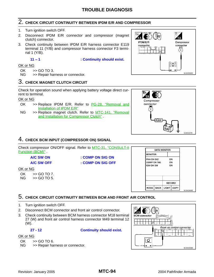
MTC-94
TROUBLE DIAGNOSIS
Revision: January 2005 2004 Pathfinder Armada
2. CHECK CIRCUIT CONTINUITY BETWEEN IPDM E/R AND COMPRESSOR
1. Turn ignition switch OFF.2. Disconnect IPDM E/R connector and compressor (magnet
clutch) connector.3. Check continuity between IPDM E/R harness connector E119
terminal 11 (Y/B) and compressor harness connector F3 termi-nal 1 (Y/B).
OK or NGOK >> GO TO 3.NG >> Repair harness or connector.
3. CHECK MAGNET CLUTCH CIRCUIT
Check for operation sound when applying battery voltage direct cur-rent to terminal.OK or NGOK >> Replace IPDM E/R. Refer to PG-28, "Removal and
Installation of IPDM E/R"NG >> Replace magnet clutch. Refer to MTC-141, "Removal
and Installation for Compressor Clutch" .
4. CHECK BCM INPUT (COMPRESSOR ON) SIGNAL
Check compressor ON/OFF signal. Refer to MTC-31, "CONSULT-IIFunction (BCM)" .
OK or NGOK >> GO TO 7.NG >> GO TO 5.
5. CHECK CIRCUIT CONTINUITY BETWEEN BCM AND FRONT AIR CONTROL
1. Turn ignition switch OFF.2. Disconnect BCM connector and front air control connector.3. Check continuity between BCM harness connector M18 terminal
27 (W) and front air control harness connector M49 terminal 12(W).
OK or NGOK >> GO TO 6.NG >> Repair harness or connector.
11 – 1 : Continuity should exist.
WJIA0560E
SJIA0197E
A/C SW ON : COMP ON SIG ONA/C SW OFF : COMP ON SIG OFF
WJIA0469E
27 - 12 Continuity should exist.
WJIA0448E

TROUBLE DIAGNOSIS
MTC-95
C
D
E
F
G
H
I
K
L
M
A
B
MTC
Revision: January 2005 2004 Pathfinder Armada
6. CHECK VOLTAGE FOR FRONT AIR CONTROL (COMPRESSOR ON SIGNAL)
1. Reconnect BCM connector and front air control connector.2. Turn ignition switch ON.3. Check voltage between front air control harness connector M49
terminal 12 (W) and ground.
OK or NGOK >> GO TO 7.NG-1 >> If the voltage is approx. 5V when A/C switch is ON, replace front air control. Refer to MTC-112,
"FRONT AIR CONTROL" .NG-2 >> If the voltage is approx. 0V when A/C switch is OFF, replace BCM. Refer to BCS-21, "Removal
and Installation of BCM" .
7. CHECK REFRIGERANT PRESSURE SENSOR
WITH CONSULT-II1. Start engine.2. Check voltage of refrigerant pressure sensor. Refer to MTC-31, "CONSULT-II Function (BCM)" .
WITHOUT CONSULT-II1. Start engine.2. Check voltage between ECM harness connector F54 terminal
70 (B/W) and ground.
OK or NGOK >> WITH CONSULT-II
GO TO 8.
WITHOUT CONSULT-IIGO TO 9.
NG >> Refer to MTC-97, "Refrigerant Pressure Sensor" .
Terminals
Condition Voltage(+)
(-)Front air control con-
nector
Terminal No.(Wire color)
M49 12 (W) GroundA/C switch: ON Approx. 0V
A/C switch: OFF Approx. 5V
WJIA0449E
Terminals
Condition Voltage(+)
(-)ECM con-nector
Terminal No.(Wire color)
F54 70 (B/W) Ground A/C switch: ON Approx. 0.36 - 3.88V
LJIA0124E

MTC-96
TROUBLE DIAGNOSIS
Revision: January 2005 2004 Pathfinder Armada
8. CHECK BCM INPUT (FAN ON) SIGNAL
Check FAN ON/OFF signal. Refer to MTC-31, "CONSULT-II Func-tion (BCM)" .
OK or NGOK >> GO TO 11.NG >> GO TO 9.
9. CHECK CIRCUIT CONTINUITY BETWEEN BCM AND FRONT AIR CONTROL
1. Turn ignition switch OFF.2. Disconnect BCM connector and front air control connector.3. Check continuity between BCM harness connector M18 terminal
28 (L/R) and front air control harness connector M49 terminal 10(L/R).
OK or NGOK >> GO TO 10.NG >> Repair harness or connector.
10. CHECK VOLTAGE FOR FRONT AIR CONTROL (FAN ON SIGNAL)
1. Reconnect BCM connector and front air control connector.2. Turn ignition switch ON.3. Check voltage between front air control harness connector M49
terminal 10 (L/R) and ground.
OK or NGOK >> GO TO 11.NG-1 >> If the voltage is approx. 5V when blower motor is ON, replace front air control. Refer to MTC-112,
"FRONT AIR CONTROL" .NG-2 >> If the voltage is approx. 0V when blower motor is OFF, replace BCM. Refer to BCS-21, "Removal
and Installation of BCM" .
11. CHECK INTAKE SENSOR CIRCUIT
Check intake sensor. Refer to MTC-109, "Intake Sensor Circuit" .OK or NGOK >> GO TO 12.NG >> Repair or replace malfunctioning part(s).
BLOWER CONTROL SWITCH ON
: FAN ON SIG ON
BLOWER CONTROL SWITCH OFF
: FAN ON SIG OFF
WJIA0469E
28 - 10 Continuity should exist.
WJIA0450E
Terminals
Condition Voltage(+)
(-)Front air con-trol connector
Terminal No.(Wire color)
M49 10 (L/R) Ground
A/C switch: ONBlower motor operates
Approx. 0V
A/C switch: OFF Approx. 5V
WJIA0451E

TROUBLE DIAGNOSIS
MTC-97
C
D
E
F
G
H
I
K
L
M
A
B
MTC
Revision: January 2005 2004 Pathfinder Armada
12. CHECK CAN COMMUNICATION
Check CAN communication. Refer to MTC-30, "CAN Communication System Description" . BCM – ECM ECM – IPDM E/R ECM – Front air controlOK or NGOK >> Inspection End.NG >> Repair or replace malfunctioning part(s).
COMPONENT INSPECTIONRefrigerant Pressure SensorThe refrigerant pressure sensor is attached to the condenser.
WJIA1600E

MTC-98
TROUBLE DIAGNOSIS
Revision: January 2005 2004 Pathfinder Armada
Insufficient Cooling EJS0028B
SYMPTOM: Insufficient cooling
INSPECTION FLOW
*1 .MTC-49, "Operational Check (Front)" .
*2 EM-12, "Checking Drive Belts". *3 MTC-60, "System Operation".
*4 EC-408, "Description" . *5 MTC-4, "Contaminated Refrigerant". *6 .MTC-99, "PERFORMANCE TEST DIAGNOSES"
*7 MTC-101, "Test Reading"
WJIA1601E

TROUBLE DIAGNOSIS
MTC-99
C
D
E
F
G
H
I
K
L
M
A
B
MTC
Revision: January 2005 2004 Pathfinder Armada
PERFORMANCE TEST DIAGNOSES
*1 MTC-101, "PERFORMANCE CHART".
*2 MTC-101, "PERFORMANCE CHART".
*3 MTC-102, "Trouble Diagnoses for Unusual Pressure".
*4 MTC-59, "Air Mix Door Motor Cir-cuit".
RJIA1601E
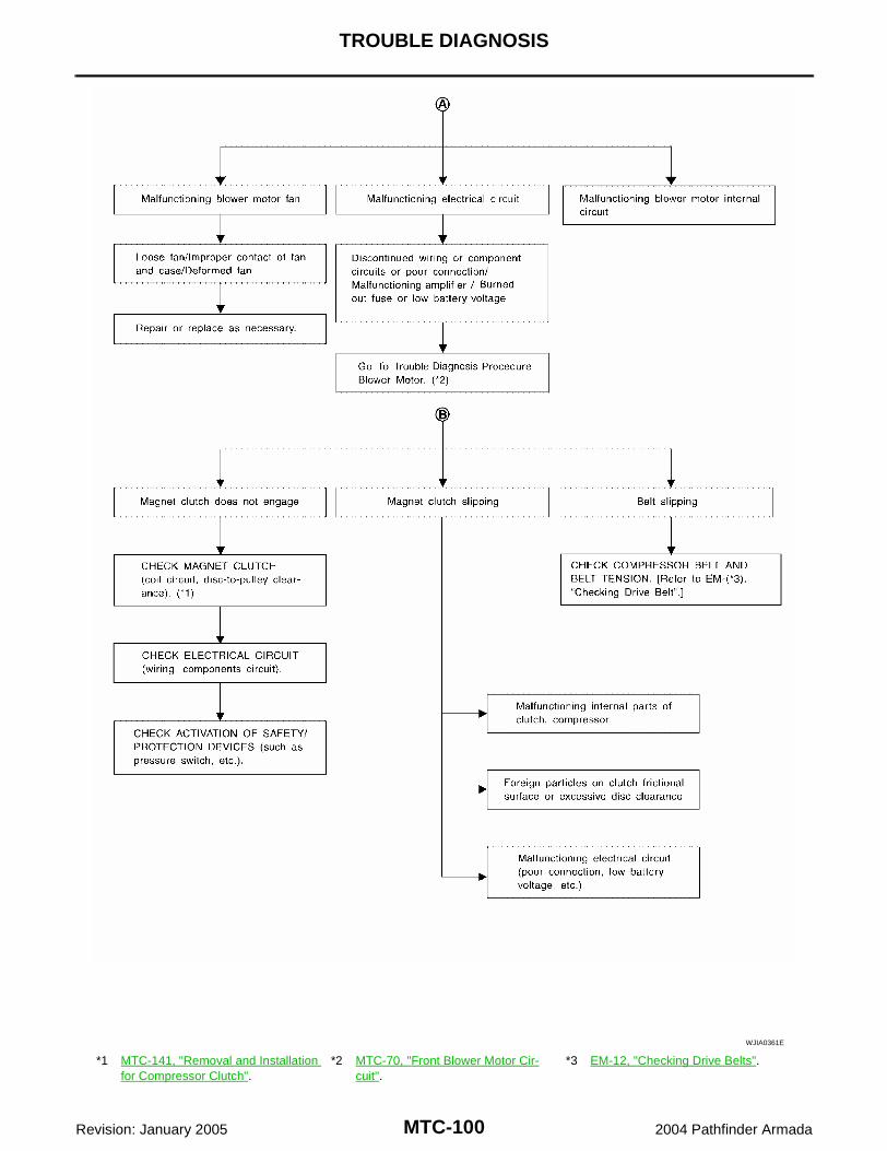
MTC-100
TROUBLE DIAGNOSIS
Revision: January 2005 2004 Pathfinder Armada
*1 MTC-141, "Removal and Installation for Compressor Clutch".
*2 MTC-70, "Front Blower Motor Cir-cuit".
*3 EM-12, "Checking Drive Belts".
WJIA0361E
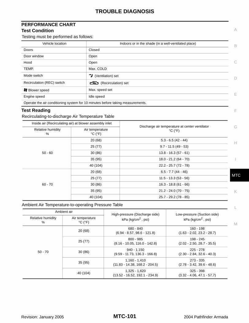
TROUBLE DIAGNOSIS
MTC-101
C
D
E
F
G
H
I
K
L
M
A
B
MTC
Revision: January 2005 2004 Pathfinder Armada
PERFORMANCE CHARTTest ConditionTesting must be performed as follows:
Test ReadingRecirculating-to-discharge Air Temperature Table
Ambient Air Temperature-to-operating Pressure Table
Vehicle location Indoors or in the shade (in a well-ventilated place)
Doors Closed
Door window Open
Hood Open
TEMP. Max. COLD
Mode switch (Ventilation) set
Recirculation (REC) switch (Recirculation) set
Blower speed Max. speed set
Engine speed Idle speed
Operate the air conditioning system for 10 minutes before taking measurements.
Inside air (Recirculating air) at blower assembly inletDischarge air temperature at center ventilator
°C (°F)Relative humidity%
Air temperature°C (°F)
50 - 60
20 (68) 5.3 - 6.5 (42 - 44)
25 (77) 9.7 - 11.5 (49 - 53)
30 (86) 13.8 - 16.3 (57 - 61)
35 (95) 18.0 - 21.2 (64 - 70)
40 (104) 22.2 - 25.7 (72 - 78)
60 - 70
20 (68) 6.5 - 7.7 (44 - 46)
25 (77) 11.5 - 13.3 (53 - 56)
30 (86) 16.3 - 18.8 (61 - 66)
35 (95) 21.2 - 24.0 (70 - 75)
40 (104) 25.7 - 29.2 (78 - 85)
Ambient airHigh-pressure (Discharge side)
kPa (kg/cm2 , psi)
Low-pressure (Suction side)
kPa (kg/cm2 , psi)Relative humidity%
Air temperature°C (°F)
50 - 70
20 (68)680 - 840
(6.94 - 8.57, 98.6 - 121.8)160 - 198
(1.63 - 2.02, 23.2 - 28.7)
25 (77)800 - 985
(8.16 - 10.05, 116.0 - 142.8)198 - 245
(2.02 - 2.50, 28.7 - 35.5)
30 (86)940 - 1,150
(9.59 - 11.73, 136.3 - 166.8)225 - 278
(2.30 - 2.84, 32.6 - 40.3)
35 (95)1,160 - 1,410
(11.83 - 14.38, 168.2 - 204.5)273 - 335
(2.78 - 3.42, 39.6 - 48.6)
40 (104)1,325 - 1,620
(13.52 - 16.52, 192.1 - 234.9)325 - 398
(3.32 - 4.06, 47.1 - 57.7)

MTC-102
TROUBLE DIAGNOSIS
Revision: January 2005 2004 Pathfinder Armada
TROUBLE DIAGNOSES FOR UNUSUAL PRESSUREWhenever system′s high and/or low side pressure is unusual, diagnose using a manifold gauge. The markerabove the gauge scale in the following tables indicates the standard (usual) pressure range. Since the stan-dard (usual) pressure, however, differs from vehicle to vehicle, refer to above table (Ambient air temperature-to-operating pressure table).
Both High- and Low-pressure Sides are Too High
High-pressure Side is Too High and Low-pressure Side is Too Low
Gauge indication Refrigerant cycle Probable cause Corrective action
Both high- and low-pressure sides are too high.
Pressure is reduced soon after water is splashed on condenser.
Excessive refrigerant charge in refrigeration cycle
Reduce refrigerant until speci-fied pressure is obtained.
Air suction by cooling fan is insufficient.
Insufficient condenser cooling performance↓1. Condenser fins are clogged.
2. Improper fan rotation of cooling fan
Clean condenser.
Check and repair cooling fan as necessary.
Low-pressure pipe is not cold.
When compressor is stopped high-pressure value quickly drops by approximately 196 kPa (2
kg/cm2 , 28 psi). It then decreases gradually there-after.
Poor heat exchange in con-denser(After compressor operation stops, high-pressure decreases too slowly.)↓Air in refrigeration cycle
Evacuate repeatedly and recharge system.
Engine tends to overheat.Engine cooling systems mal-function.
Check and repair engine cool-ing system.
An area of the low-pres-sure pipe is colder than areas near the evaporator outlet.
Plates are sometimes cov-ered with frost.
Excessive liquid refrigerant on low-pressure side
Excessive refrigerant dis-charge flow
Expansion valve is open a little compared with the specification.
↓Improper expansion valve adjustment
Replace expansion valve.
AC359A
Gauge indication Refrigerant cycle Probable cause Corrective action
High-pressure side is too high and low-pressure side is too low.
Upper side of condenser and high-pressure side are hot, however, liquid tank is not so hot.
High-pressure tube or parts located between compressor and condenser are clogged or crushed.
Check and repair or replace malfunctioning parts.
Check lubricant for contami-nation.
AC360A

TROUBLE DIAGNOSIS
MTC-103
C
D
E
F
G
H
I
K
L
M
A
B
MTC
Revision: January 2005 2004 Pathfinder Armada
High-pressure Side is Too Low and Low-pressure Side is Too High
Both High- and Low-pressure Sides are Too Low
Gauge indication Refrigerant cycle Probable cause Corrective action
High-pressure side is too low and low-pressure side is too high. High- and low-pressure sides
become equal soon after com-pressor operation stops.
Compressor pressure opera-tion is improper.↓Damaged inside compressor packings.
Replace compressor.
No temperature difference between high- and low-pres-sure sides.
Compressor pressure opera-tion is improper.↓Damaged inside compressor packings.
Replace compressor.
AC356A
Gauge indication Refrigerant cycle Probable cause Corrective action
Both high- and low-pressure sides are too low.
There is a big temperature difference between receiver drier outlet and inlet. Outlet temperature is extremely low.
Liquid tank inlet and expan-sion valve are frosted.
Liquid tank inside is slightly clogged.
Replace liquid tank.
Check lubricant for contami-nation.
Temperature of expansion valve inlet is extremely low as compared with areas near liquid tank.
Expansion valve inlet may be frosted.
Temperature difference occurs somewhere in high-pressure side.
High-pressure pipe located between receiver drier and expansion valve is clogged.
Check and repair malfunc-tioning parts.
Check lubricant for contami-nation.
Expansion valve and liquid tank are warm or only cool when touched.
Low refrigerant charge.↓Leaking fittings or compo-nents.
Check refrigerant system for leaks. Refer to MTC-150, "Checking for Refrigerant Leaks"
There is a big temperature dif-ference between expansion valve inlet and outlet while the valve itself is frosted.
Expansion valve closes a little compared with the specifica-tion.↓1. Improper expansion valve
adjustment.
2. Malfunctioning expansion valve.
3. Outlet and inlet may be clogged.
Remove foreign particles by using compressed air.
Check lubricant for contami-nation.
An area of the low-pressure pipe is colder than areas near the evaporator outlet.
Low-pressure pipe is clogged or crushed.
Check and repair malfunc-tioning parts.
Check lubricant for contami-nation.
Air flow volume is too low. Evaporator is frozen.
Check intake sensor circuit.Refer to MTC-109, "Intake Sensor Circuit" .
Replace compressor.
AC353A

MTC-104
TROUBLE DIAGNOSIS
Revision: January 2005 2004 Pathfinder Armada
Low-pressure Side Sometimes Becomes Negative
Low-pressure Side Becomes Negative
Gauge indication Refrigerant cycle Probable cause Corrective action
Low-pressure side sometimes becomes negative. Air conditioning system
does not function and does not cyclically cool the com-partment air.
The system constantly func-tions for a certain period of time after compressor is stopped and restarted.
Refrigerant does not dis-charge cyclically.↓Moisture is frozen at expan-sion valve outlet and inlet.↓Water is mixed with refriger-ant.
Drain water from refrigerant or replace refrigerant.
Replace liquid tank.
AC354A
Gauge indication Refrigerant cycle Probable cause Corrective action
Low-pressure side becomes nega-tive.
Liquid tank or front/rear side of expansion valve′s pipe is frosted or dewed.
High-pressure side is closed and refrigerant does not flow.↓Expansion valve or liquid tank is frosted.
Leave the system at rest until no frost is present. Start it again to check whether or not the malfunction is caused by water or foreign particles.
If water is the cause, initially cooling is okay. Then the water freezes causing a blockage. Drain water from refrigerant or replace refrig-erant.
If due to foreign particles, remove expansion valve and remove the particles with dry and compressed air (not shop air).
If either of the above meth-ods cannot correct the mal-function, replace expansion valve.
Replace liquid tank.
Check lubricant for contami-nation.
AC362A
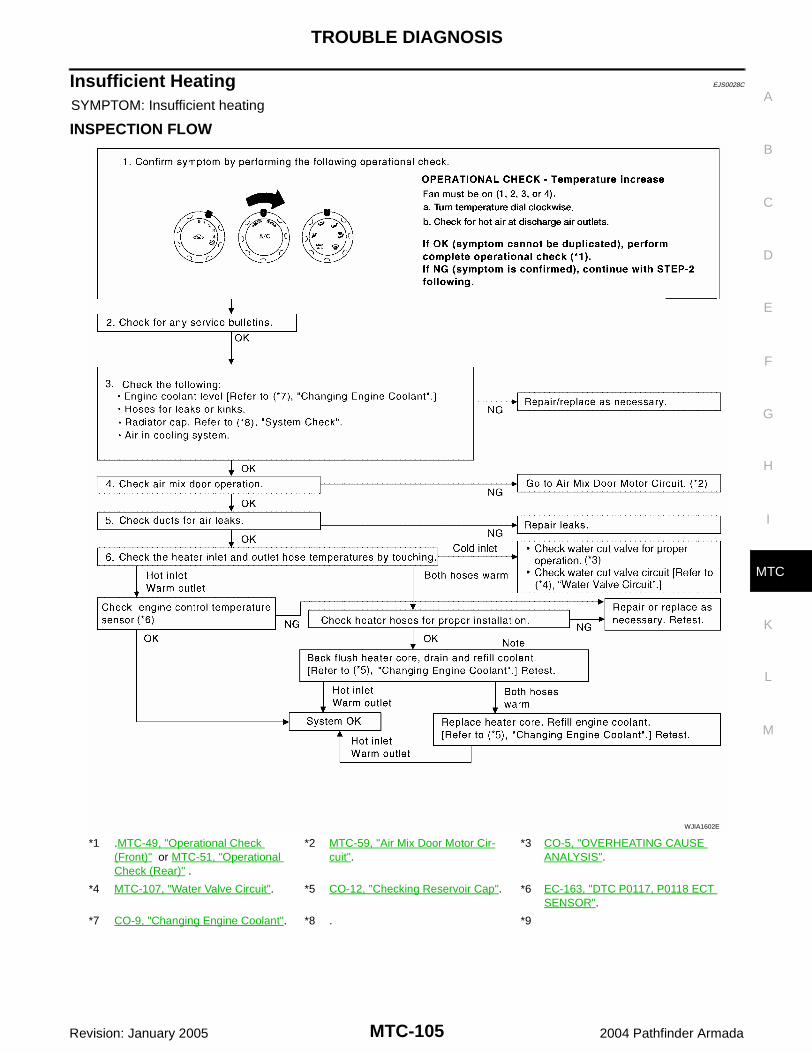
TROUBLE DIAGNOSIS
MTC-105
C
D
E
F
G
H
I
K
L
M
A
B
MTC
Revision: January 2005 2004 Pathfinder Armada
Insufficient Heating EJS0028C
SYMPTOM: Insufficient heating
INSPECTION FLOW
*1 .MTC-49, "Operational Check (Front)" or MTC-51, "Operational Check (Rear)" .
*2 MTC-59, "Air Mix Door Motor Cir-cuit".
*3 CO-5, "OVERHEATING CAUSE ANALYSIS".
*4 MTC-107, "Water Valve Circuit". *5 CO-12, "Checking Reservoir Cap". *6 EC-163, "DTC P0117, P0118 ECT SENSOR".
*7 CO-9, "Changing Engine Coolant". *8 . *9
WJIA1602E

MTC-106
TROUBLE DIAGNOSIS
Revision: January 2005 2004 Pathfinder Armada
Noise EJS0028V
SYMPTOM: Noise
INSPECTION FLOW
WJIA0473E
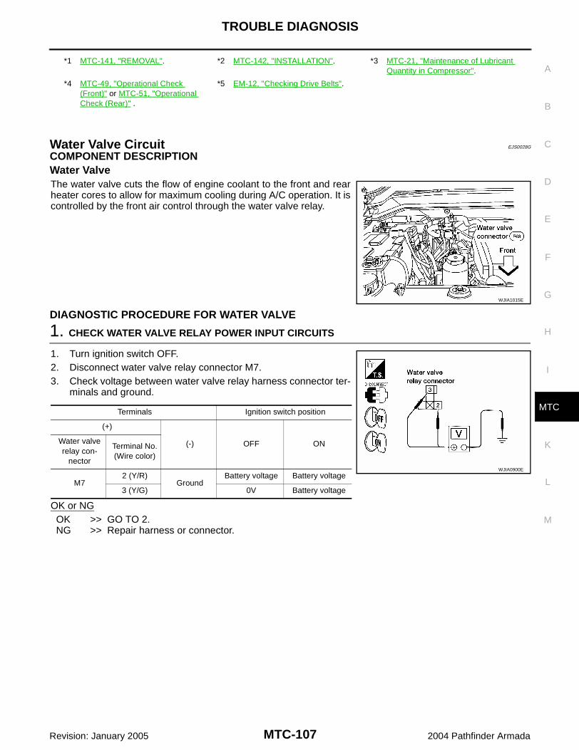
TROUBLE DIAGNOSIS
MTC-107
C
D
E
F
G
H
I
K
L
M
A
B
MTC
Revision: January 2005 2004 Pathfinder Armada
Water Valve Circuit EJS0028G
COMPONENT DESCRIPTIONWater ValveThe water valve cuts the flow of engine coolant to the front and rearheater cores to allow for maximum cooling during A/C operation. It iscontrolled by the front air control through the water valve relay.
DIAGNOSTIC PROCEDURE FOR WATER VALVE
1. CHECK WATER VALVE RELAY POWER INPUT CIRCUITS
1. Turn ignition switch OFF.2. Disconnect water valve relay connector M7.3. Check voltage between water valve relay harness connector ter-
minals and ground.
OK or NGOK >> GO TO 2.NG >> Repair harness or connector.
*1 MTC-141, "REMOVAL". *2 MTC-142, "INSTALLATION". *3 MTC-21, "Maintenance of Lubricant Quantity in Compressor".
*4 MTC-49, "Operational Check (Front)" or MTC-51, "Operational Check (Rear)" .
*5 EM-12, "Checking Drive Belts".
WJIA1015E
Terminals Ignition switch position
(+)
(-) OFF ONWater valve relay con-
nector
Terminal No.(Wire color)
M72 (Y/R)
GroundBattery voltage Battery voltage
3 (Y/G) 0V Battery voltage
WJIA0900E

MTC-108
TROUBLE DIAGNOSIS
Revision: January 2005 2004 Pathfinder Armada
2. CHECK WATER VALVE CONTROL
1. Turn ignition switch ON.2. Select MAX A/C with mode switch.3. Check continuity between water valve relay harness connector
M7 terminal 1 (W/G) and ground, as MAX A/C is switched OFFand ON.
OK or NGOK >> GO TO 4.NG >> GO TO 3.
3. CHECK WATER VALVE CONTROL OUTPUT CIRCUIT
1. Turn ignition switch OFF.2. Disconnect front air control connector M49.3. Check continuity between water valve relay harness connector
M7 terminal 1 (W/G) and front air control harness connectorM49 terminal 10 (W/G).
4. Check continuity between water valve relay harness connectorM7 terminal 1 (W/G) and ground.
OK or NGOK >> Replace front air control. Refer to MTC-112, "FRONT AIR CONTROL" .NG >> Repair harness or connector.
4. CHECK WATER VALVE RELAY
Check water valve relay. Refer to MTC-109, "Water Valve Relay" .OK or NGOK >> GO TO 5NG >> Replace water valve relay.
5. CHECK WATER VALVE GROUND CIRCUIT
1. Turn ignition switch OFF.2. Disconnect water valve connector F68.3. Check continuity between water valve harness connector F68
terminal - (B) and ground.
OK or NGOK >> GO TO 6.NG >> Repair harness or connector.
Terminals
Condition Continuity(+)
(-)Water valve relay con-
nector
Terminal No.(Wire color)
M7 1 (W/G) GroundMAX A/C: ON Yes
MAX A/C: OFF No
WJIA0901E
1 - 10 : Continuity should exist.
1 - Ground : Continuity should not exist. WJIA1014E
(-) - Ground : Continuity should exist.
WJIA0816E

TROUBLE DIAGNOSIS
MTC-109
C
D
E
F
G
H
I
K
L
M
A
B
MTC
Revision: January 2005 2004 Pathfinder Armada
6. CHECK WATER VALVE POWER CIRCUIT
1. Check continuity between water valve relay connector terminal 5(Y/L) and water valve connector F68 terminal + (Y/L)
2. Check continuity between water valve relay harness connectorM7 terminal 5 (Y/L) and ground.
OK or NGOK >> Replace water valve. NG >> Repair harness or connector.
COMPONENT INSPECTIONWater Valve RelayCheck continuity between terminals 3 and 5 by supplying 12 voltsand ground to coil side terminals of relay.
Intake Sensor Circuit EJS0028K
COMPONENT DESCRIPTIONIntake SensorThe intake sensor is located on the heater & cooling unit. It convertstemperature of air after it passes through the evaporator into a resis-tance value which is then input to the front air control.
DIAGNOSTIC PROCEDURE FOR INTAKE SENSORSYMPTOM: Intake sensor circuit is open or shorted.
5 - + : Continuity should exist.
5 - Ground : Continuity should not exist.
WJIA0903E
LHA160
WJIA0571E
WJIA0464E

MTC-110
TROUBLE DIAGNOSIS
Revision: January 2005 2004 Pathfinder Armada
1. CHECK VOLTAGE BETWEEN INTAKE SENSOR AND GROUND
1. Disconnect intake sensor connector.2. Turn ignition switch ON.3. Check voltage between intake sensor harness connector M146
terminal 2 (L/B) and ground.
OK or NGOK >> GO TO 2.NG >> GO TO 4.
2. CHECK CIRCUIT CONTINUITY BETWEEN INTAKE SENSOR AND FRONT AIR CONTROL
1. Turn ignition switch OFF.2. Disconnect front air control connector.3. Check continuity between intake sensor harness connector
M146 terminal 1 (V/R) and front air control harness connectorM49 terminal 21 (V/R).
OK or NGOK >> GO TO 3.NG >> Repair harness or connector.
3. CHECK INTAKE SENSOR
Refer to MTC-111, "Intake Sensor" .OK or NGOK >> Replace front air control. Refer to MTC-112, "FRONT AIR CONTROL" .NG >> Replace intake sensor. Refer to MTC-113, "INTAKE SENSOR" .
4. CHECK CIRCUIT CONTINUITY BETWEEN INTAKE SENSOR AND FRONT AIR CONTROL
1. Turn ignition switch OFF.2. Disconnect front air control connector.3. Check continuity between intake sensor harness connector
M146 terminal 2 (L/B) and front air control harness connectorM49 terminal 9 (L/B).
4. Check continuity between intake sensor harness connectorM146 terminal 2 (L/B) and ground.
OK or NGOK >> Replace front air control. Refer to MTC-112, "FRONT AIR CONTROL"NG >> Repair harness or connector.
2 - Ground : Approx. 5V
WJIA0465E
1 - 21 : Continuity should exist.
WJIA0466E
2 - 9 : Continuity should exist.
2 - Ground : Continuity should not exist. LJIA0125E

TROUBLE DIAGNOSIS
MTC-111
C
D
E
F
G
H
I
K
L
M
A
B
MTC
Revision: January 2005 2004 Pathfinder Armada
COMPONENT INSPECTIONIntake SensorAfter disconnecting intake sensor connector, measure resistancebetween terminals 1 and 2 at sensor harness side, using the tablebelow.
If NG, replace intake sensor.
Temperature °C (°F) Resistance kΩ
−15 (5) 209.0
−10 (14) 160.0
−5 (23) 123.0
0 (32) 95.8
5 (41) 74.9
10 (50) 58.9
15 (59) 46.7
20 (68) 37.3
25 (77) 30.0
30 (86) 24.2
35 (95) 19.7
40 (104) 16.1
45 (113) 13.2
WJIA0572E

MTC-112
CONTROL UNIT
Revision: January 2005 2004 Pathfinder Armada
CONTROL UNIT PFP:27500
Removal and Installation EJS0025W
FRONT AIR CONTROLRemoval1. Remove the five control knobs from the front air control unit.2. Remove the cluster lid C. Refer to IP-11, "CLUSTER LID C" .3. Remove the four screws securing the front air control unit to the
cluster lid C.4. Remove the front air control unit.
InstallationInstallation is in the reverse order of removal.
REAR AIR CONTROLRemoval1. Remove the overhead console from the headliner. Refer to EI-33, "HEADLINING" .2. Remove the four screws and remove the rear air control.
InstallationInstallation is in the reverse order of removal.
LJIA0130E
LJIA0131E
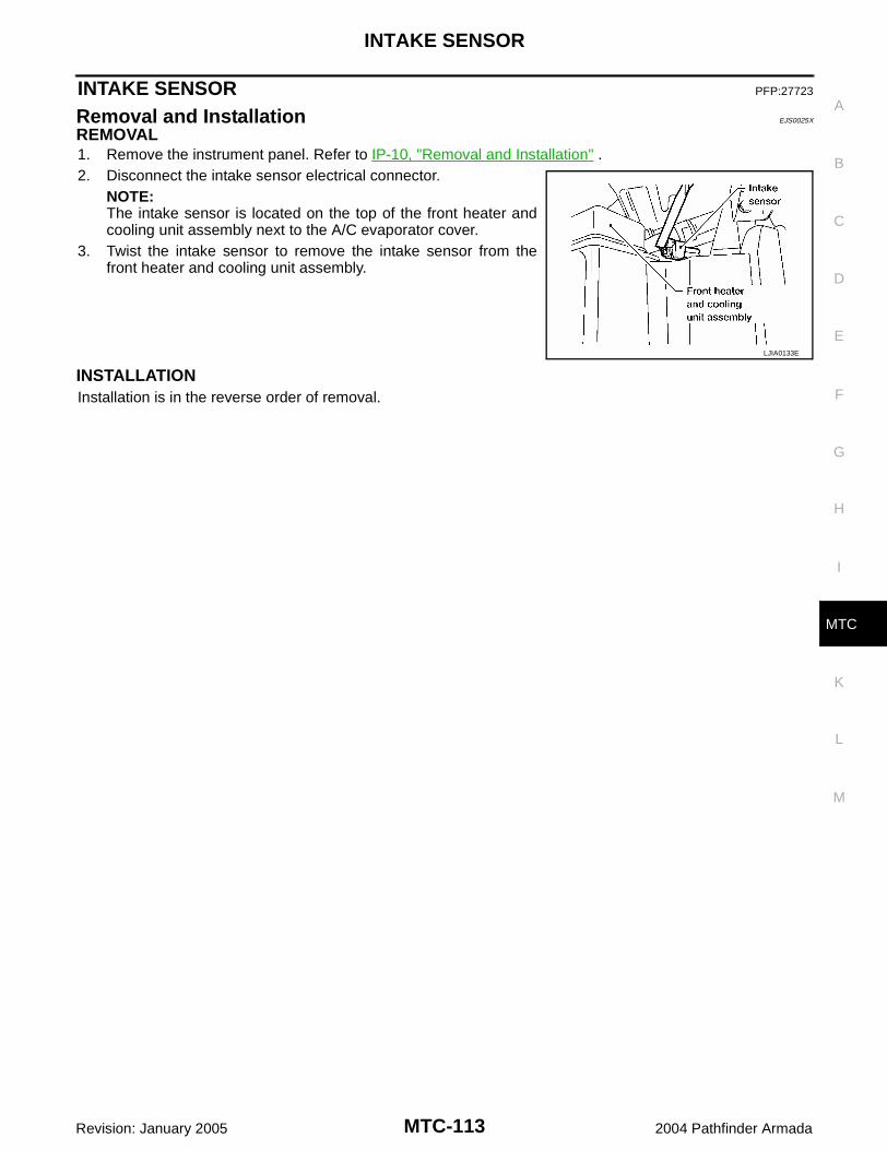
INTAKE SENSOR
MTC-113
C
D
E
F
G
H
I
K
L
M
A
B
MTC
Revision: January 2005 2004 Pathfinder Armada
INTAKE SENSOR PFP:27723
Removal and Installation EJS0025X
REMOVAL1. Remove the instrument panel. Refer to IP-10, "Removal and Installation" .2. Disconnect the intake sensor electrical connector.
NOTE:The intake sensor is located on the top of the front heater andcooling unit assembly next to the A/C evaporator cover.
3. Twist the intake sensor to remove the intake sensor from thefront heater and cooling unit assembly.
INSTALLATIONInstallation is in the reverse order of removal.
LJIA0133E

MTC-114
BLOWER MOTOR
Revision: January 2005 2004 Pathfinder Armada
BLOWER MOTOR PFP:27226
Components EJS0025Y
Front Blower Motor
Rear Blower Motor
Removal and Installation EJS0025Z
FRONT BLOWER MOTORRemoval1. Remove the glove box assembly. Refer toIP-10, "Removal and Installation" .2. Disconnect the front blower motor electrical connector.3. Remove the three screws and remove the front blower motor.
InstallationInstallation is in the reverse order of removal.
LJIA0136E
1. Front heater and cooling unit assembly 2. Front blower motor 3. Front blower motor resistor
LJIA0055E
1. Rear blower motor 2. Rear blower motor case 3. Rear blower motor resistor

BLOWER MOTOR
MTC-115
C
D
E
F
G
H
I
K
L
M
A
B
MTC
Revision: January 2005 2004 Pathfinder Armada
REAR BLOWER MOTORRemoval1. Remove the rear RH interior trim panel. Refer to EI-30, "Removal and Installation" .2. Disconnect the rear blower motor electrical connector.3. Remove the three screws and remove the rear blower motor.
InstallationInstallation is in the reverse order of removal.
LJIA0056E

MTC-116
IN-CABIN MICROFILTER
Revision: January 2005 2004 Pathfinder Armada
IN-CABIN MICROFILTER PFP:27277
Removal and Installation EJS00272
FUNCTIONThe air inside the passenger compartment is filtered by the in-cabinmicrofilters when the heater or A/C controls are set on either therecirculation or fresh mode. The two in-cabin microfilters are locatedin the front heater and cooling unit assembly. The rear heater andcooling unit assembly only draws in air from the passenger compart-ment to recirculate into the passenger compartment, so the rearheater and cooling unit assembly is not equipped with in-cabinmicrofilters.
REPLACEMENT TIMINGReplacement of the two in-cabin microfilters is recommended on a regular interval depending on the drivingconditions. Refer to MA-7, "PERIODIC MAINTENANCE" . It may also be necessary to replace the two in-cabinmicrofilters as part of a component replacement if the in-cabin microfilters are damaged.
REPLACEMENT PROCEDURE1. Remove the two lower glove box hinge pins to remove the glove
box from the instrument panel and let it hang from the cord.
2. Remove the screw and remove the in-cabin microfilter cover.3. Remove the in-cabin microfilters from the front heater and cool-
ing unit assembly housing.
4. Insert the first new in-cabin microfilter into the front heater andcooling unit assembly housing and slide it over to the right.Insert the second new in-cabin microfilter into the front heaterand cooling unit assembly housing.NOTE:The in-cabin microfilters are marked with air flow arrows. Theend of the microfilter with the arrow should face the rear of thevehicle. The arrows should point downward.
LJIA0012E
WLIA0027E
LJIA0134E
LJIA0148E

IN-CABIN MICROFILTER
MTC-117
C
D
E
F
G
H
I
K
L
M
A
B
MTC
Revision: January 2005 2004 Pathfinder Armada
5. Install the in-cabin microfilter cover.
6. Install the lower glove box in the instrument panel and secure itwith the two hinge pins.
LJIA0134E
WLIA0027E
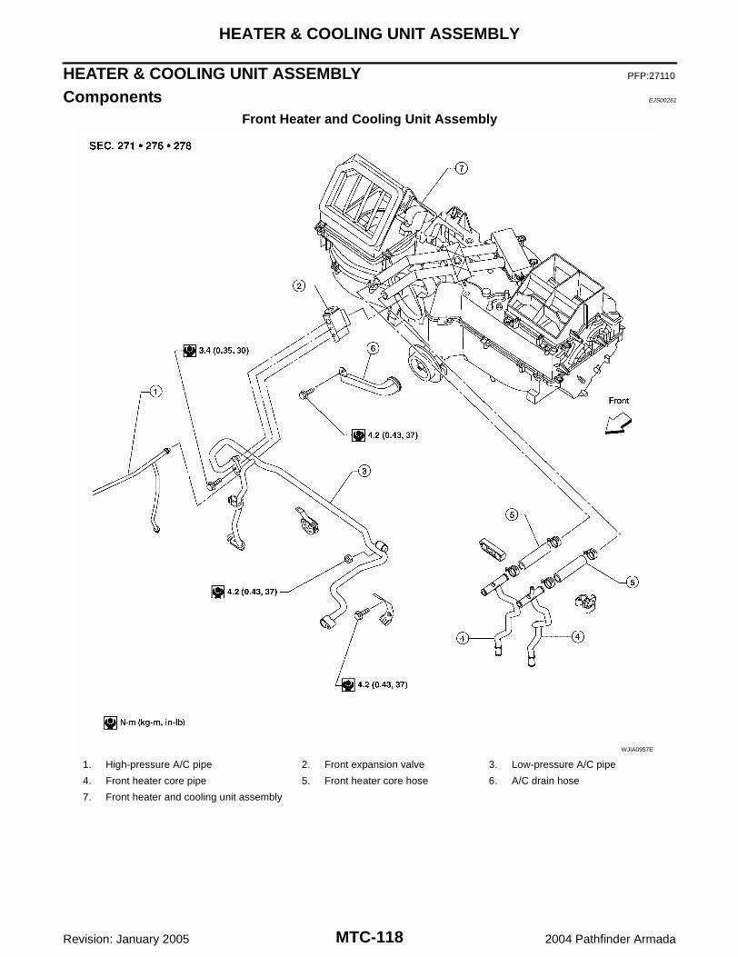
MTC-118
HEATER & COOLING UNIT ASSEMBLY
Revision: January 2005 2004 Pathfinder Armada
HEATER & COOLING UNIT ASSEMBLY PFP:27110
Components EJS00261
Front Heater and Cooling Unit Assembly
WJIA0957E
1. High-pressure A/C pipe 2. Front expansion valve 3. Low-pressure A/C pipe
4. Front heater core pipe 5. Front heater core hose 6. A/C drain hose
7. Front heater and cooling unit assembly

HEATER & COOLING UNIT ASSEMBLY
MTC-119
C
D
E
F
G
H
I
K
L
M
A
B
MTC
Revision: January 2005 2004 Pathfinder Armada
Rear Heater and Cooling Unit Assembly
Removal and Installation EJS00262
FRONT HEATER AND COOLING UNIT ASSEMBLYRemoval1. Discharge the refrigerant from the A/C system. Refer to MTC-136, "Discharging Refrigerant" .2. Drain the coolant from the engine cooling system. Refer to MA-13, "DRAINING ENGINE COOLANT" .3. Remove the cowl top extension. Refer to EI-18, "Removal and Installation" .4. Remove the exhaust system. Refer to EX-3, "Removal and Installation" .5. Disconnect the front heater hoses from the front heater core.6. Disconnect the high/low pressure pipes from the front expansion valve.
LJIA0066E
1. Rear heater and cooling unit assembly 2. Rear A/C pipes 3. Rear heater core pipes
4. Rear heater core hose 5. Rear blower motor 6. Underfloor rear A/C pipes
7. Underfloor rear heater core pipes
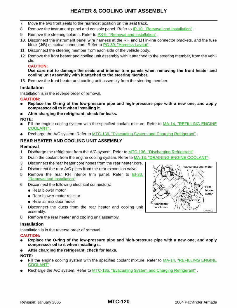
MTC-120
HEATER & COOLING UNIT ASSEMBLY
Revision: January 2005 2004 Pathfinder Armada
7. Move the two front seats to the rearmost position on the seat track.8. Remove the instrument panel and console panel. Refer to IP-10, "Removal and Installation" .9. Remove the steering column. Refer to PS-9, "Removal and Installation" .10. Disconnect the instrument panel wire harness at the RH and LH in-line connector brackets, and the fuse
block (J/B) electrical connectors. Refer to PG-39, "Harness Layout" .11. Disconnect the steering member from each side of the vehicle body.12. Remove the front heater and cooling unit assembly with it attached to the steering member, from the vehi-
cle.CAUTION:Use care not to damage the seats and interior trim panels when removing the front heater andcooling unit assembly with it attached to the steering member.
13. Remove the front heater and cooling unit assembly from the steering member.
InstallationInstallation is in the reverse order of removal.CAUTION: Replace the O-ring of the low-pressure pipe and high-pressure pipe with a new one, and apply
compressor oil to it when installing it. After charging the refrigerant, check for leaks.NOTE: Fill the engine cooling system with the specified coolant mixture. Refer to MA-14, "REFILLING ENGINE
COOLANT" . Recharge the A/C system. Refer to MTC-136, "Evacuating System and Charging Refrigerant" .
REAR HEATER AND COOLING UNIT ASSEMBLYRemoval1. Discharge the refrigerant from the A/C system. Refer to MTC-136, "Discharging Refrigerant" .2. Drain the coolant from the engine cooling system. Refer to MA-13, "DRAINING ENGINE COOLANT" .3. Disconnect the rear heater core hoses from the rear heater core.4. Disconnect the rear A/C pipes from the rear expansion valve.5. Remove the rear RH interior trim panel. Refer to EI-30,
"Removal and Installation" .6. Disconnect the following electrical connectors:
Rear blower motor Rear blower motor resistor Rear air mix door motor
7. Disconnect the ducts from the rear heater and cooling unitassembly.
8. Remove the rear heater and cooling unit assembly.
InstallationInstallation is in the reverse order of removal.CAUTION: Replace the O-ring of the low-pressure pipe and high-pressure pipe with a new one, and apply
compressor oil to it when installing it. After charging the refrigerant, check for leaks.NOTE: Fill the engine cooling system with the specified coolant mixture. Refer to MA-14, "REFILLING ENGINE
COOLANT" . Recharge the A/C system. Refer to MTC-136, "Evacuating System and Charging Refrigerant" .
LJIA0021E

HEATER CORE
MTC-121
C
D
E
F
G
H
I
K
L
M
A
B
MTC
Revision: January 2005 2004 Pathfinder Armada
HEATER CORE PFP:27140
Components EJS00263
Front Heater and Cooling Unit Assembly
LJIA0138E
1. Heater core cover 2. Heater core pipe bracket 3. Heater core
4. Upper bracket 5. Upper heater and cooling unit case 6. A/C evaporator
7. Lower heater and cooling unit case 8. Blower motor 9. Front blower motor resistor
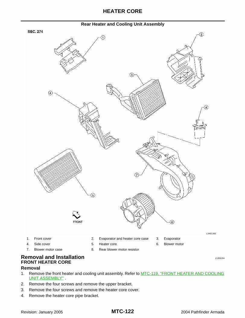
MTC-122
HEATER CORE
Revision: January 2005 2004 Pathfinder Armada
Rear Heater and Cooling Unit Assembly
Removal and Installation EJS00264
FRONT HEATER CORERemoval1. Remove the front heater and cooling unit assembly. Refer to MTC-119, "FRONT HEATER AND COOLING
UNIT ASSEMBLY" .2. Remove the four screws and remove the upper bracket.3. Remove the four screws and remove the heater core cover.4. Remove the heater core pipe bracket.
LJIA0135E
1. Front cover 2. Evaporator and heater core case 3. Evaporator
4. Side cover 5. Heater core 6. Blower motor
7. Blower motor case 8. Rear blower motor resistor

HEATER CORE
MTC-123
C
D
E
F
G
H
I
K
L
M
A
B
MTC
Revision: January 2005 2004 Pathfinder Armada
5. Remove the heater core.NOTE:If the in-cabin microfilters are contaminated from coolant leakingfrom the heater core, replace the in-cabin microfilters with newones before installing the new heater core.
InstallationInstallation is in the reverse order of removal.
REAR HEATER CORERemoval1. Partially drain the engine cooling system. Refer to MA-13, "DRAINING ENGINE COOLANT" .2. Remove the rear RH interior trim panel. Refer to EI-30, "Removal and Installation" .3. Disconnect the rear heater hoses from the heater core.
4. Remove the rear heater core bracket.5. Remove the heater core.
InstallationInstallation is in the reverse order of removal.
LJIA0134E
LJIA0069E
LJIA0071E

MTC-124
DEFROSTER DOOR MOTOR
Revision: January 2005 2004 Pathfinder Armada
DEFROSTER DOOR MOTOR PFP:27733
Removal and Installation EJS00265
Defroster Door Motor - Front Heater and Cooling Unit Assembly
REMOVAL1. Remove the front heater and cooling unit assembly. Refer to MTC-119, "FRONT HEATER AND COOLING
UNIT ASSEMBLY" .2. Remove the steering member from the front heater and cooling unit assembly.3. Disconnect the defroster door motor electrical connector.4. Remove the three screws and remove the defroster door motor.
INSTALLATIONInstallation is in the reverse order of removal.
WJIA0622E
1. Front heater and cooling unit assembly 2. Intake door motor 3. Air mix door motor
4. Front blower motor resistor 5. Mode door motor 6. Defroster door motor

INTAKE DOOR MOTOR
MTC-125
C
D
E
F
G
H
I
K
L
M
A
B
MTC
Revision: January 2005 2004 Pathfinder Armada
INTAKE DOOR MOTOR PFP:27730
Removal and Installation EJS00266
Intake Door Motor - Front Heater and Cooling Unit Assembly
REMOVAL1. Remove the front heater and cooling unit assembly. Refer to MTC-119, "FRONT HEATER AND COOLING
UNIT ASSEMBLY" .2. Remove the steering member from the front heater and cooling unit assembly.3. Disconnect the intake door motor electrical connector.4. Remove the three screws and remove the intake door motor.
INSTALLATIONInstallation is in the reverse order of removal.
WJIA0622E
1. Front heater and cooling unit assembly 2. Intake door motor 3. Air mix door motor
4. Front blower motor resistor 5. Mode door motor 6. Defroster door motor

MTC-126
MODE DOOR MOTOR
Revision: January 2005 2004 Pathfinder Armada
MODE DOOR MOTOR PFP:27731
Removal and Installation EJS00267
Mode Door Motor - Front Heater and Cooling Unit Assembly
REMOVAL1. Remove the front heater and cooling unit assembly. Refer to MTC-119, "FRONT HEATER AND COOLING
UNIT ASSEMBLY" .2. Remove the steering member from the front heater and cooling unit assembly.3. Disconnect the mode door motor electrical connector.4. Remove the two screws and remove the mode door motor.
INSTALLATIONInstallation is in the reverse order of removal.
WJIA0622E
1. Front heater and cooling unit assembly 2. Intake door motor 3. Air mix door motor
4. Front blower motor resistor 5. Mode door motor 6. Defroster door motor

AIR MIX DOOR MOTOR
MTC-127
C
D
E
F
G
H
I
K
L
M
A
B
MTC
Revision: January 2005 2004 Pathfinder Armada
AIR MIX DOOR MOTOR PFP:27732
Components EJS00268
Air Mix Door Motor - Front Heater and Cooling Unit Assembly
Removal and Installation EJS00269
FRONT AIR MIX DOOR MOTORRemoval1. Remove the front heater and cooling unit assembly. Refer to MTC-119, "FRONT HEATER AND COOLING
UNIT ASSEMBLY" .2. Remove the steering member from the front heater and cooling unit assembly.3. Disconnect the air mix door motor electrical connector.4. Remove the three screws and remove the air mix door motor.
InstallationInstallation is in the reverse order of removal.
WJIA0622E
1. Front heater and cooling unit assembly 2. Intake door motor 3. Air mix door motor
4. Front blower motor resistor 5. Mode door motor 6. Defroster door motor
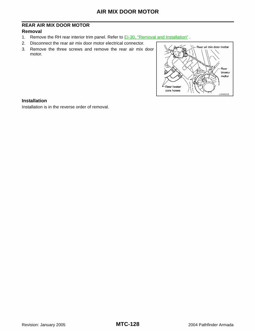
MTC-128
AIR MIX DOOR MOTOR
Revision: January 2005 2004 Pathfinder Armada
REAR AIR MIX DOOR MOTORRemoval1. Remove the RH rear interior trim panel. Refer to EI-30, "Removal and Installation" .2. Disconnect the rear air mix door motor electrical connector.3. Remove the three screws and remove the rear air mix door
motor.
InstallationInstallation is in the reverse order of removal.
LJIA0021E
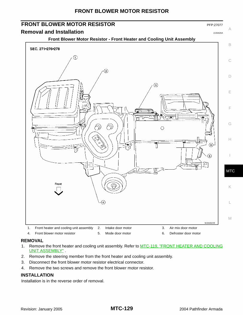
FRONT BLOWER MOTOR RESISTOR
MTC-129
C
D
E
F
G
H
I
K
L
M
A
B
MTC
Revision: January 2005 2004 Pathfinder Armada
FRONT BLOWER MOTOR RESISTOR PFP:27077
Removal and Installation EJS0026A
Front Blower Motor Resistor - Front Heater and Cooling Unit Assembly
REMOVAL1. Remove the front heater and cooling unit assembly. Refer to MTC-119, "FRONT HEATER AND COOLING
UNIT ASSEMBLY" .2. Remove the steering member from the front heater and cooling unit assembly.3. Disconnect the front blower motor resistor electrical connector.4. Remove the two screws and remove the front blower motor resistor.
INSTALLATIONInstallation is in the reverse order of removal.
WJIA0622E
1. Front heater and cooling unit assembly 2. Intake door motor 3. Air mix door motor
4. Front blower motor resistor 5. Mode door motor 6. Defroster door motor
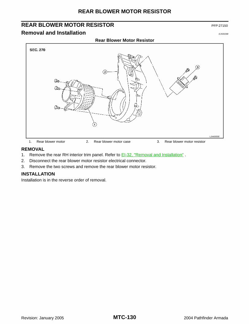
MTC-130
REAR BLOWER MOTOR RESISTOR
Revision: January 2005 2004 Pathfinder Armada
REAR BLOWER MOTOR RESISTOR PFP:27150
Removal and Installation EJS0026B
Rear Blower Motor Resistor
REMOVAL1. Remove the rear RH interior trim panel. Refer to EI-32, "Removal and Installation" .2. Disconnect the rear blower motor resistor electrical connector.3. Remove the two screws and remove the rear blower motor resistor.
INSTALLATIONInstallation is in the reverse order of removal.
LJIA0055E
1. Rear blower motor 2. Rear blower motor case 3. Rear blower motor resistor
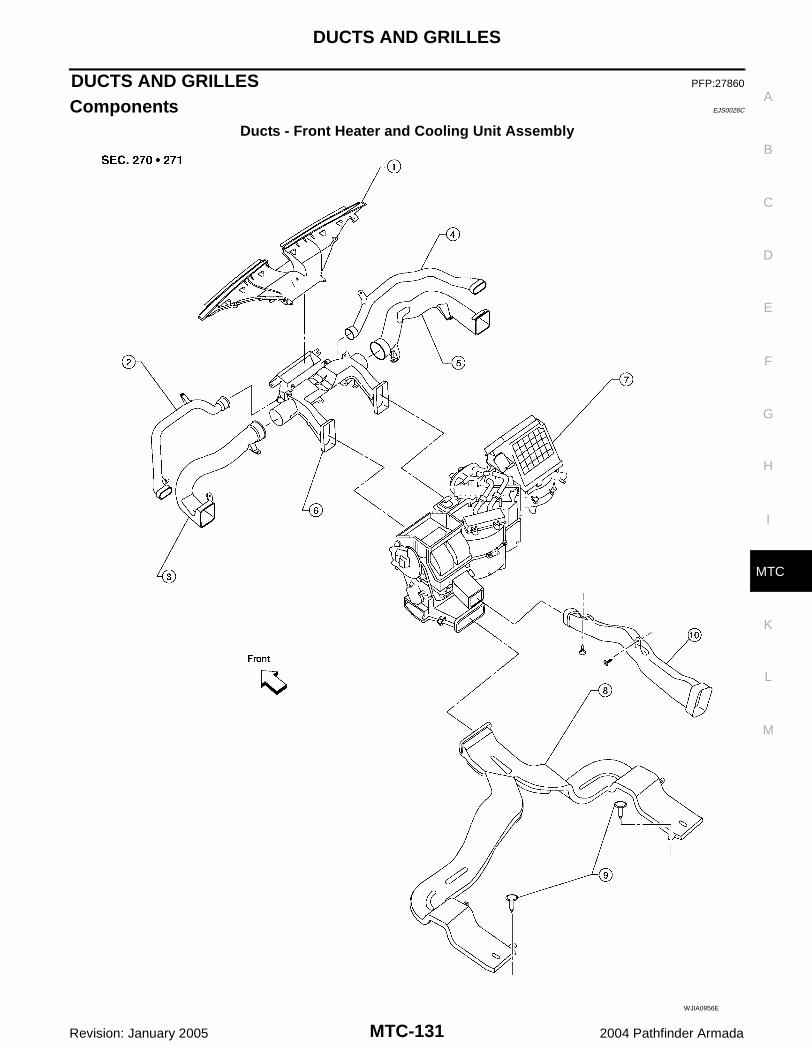
DUCTS AND GRILLES
MTC-131
C
D
E
F
G
H
I
K
L
M
A
B
MTC
Revision: January 2005 2004 Pathfinder Armada
DUCTS AND GRILLES PFP:27860
Components EJS0026C
Ducts - Front Heater and Cooling Unit Assembly
WJIA0956E

MTC-132
DUCTS AND GRILLES
Revision: January 2005 2004 Pathfinder Armada
Ducts - Rear Heater and Cooling Unit Assembly
1. Defroster nozzle 2. LH side demister duct 3. LH ventilator duct
4. RH side demister duct 5. RH ventilator duct 6. Center ventilator duct
7. Front heater and cooling unit assembly 8. Floor duct 9. Clips
10. Heat duct
LJIA0142E
1. Rear floor duct 2. Rear heater and cooling unit assembly 3. Rear lower overhead duct
4. Rear upper overhead duct

DUCTS AND GRILLES
MTC-133
C
D
E
F
G
H
I
K
L
M
A
B
MTC
Revision: January 2005 2004 Pathfinder Armada
Grilles
LJIA0140E
1. Overhead console trim panel 2. Overhead console front grilles (front) 3. Overhead console rear grilles (rear)
4. Instrument panel 5. Storage tray bottom cover (LH) 6. LH side ventilator and demister grille
MTC-134
DUCTS AND GRILLES
Revision: January 2005 2004 Pathfinder Armada
Removal and Installation EJS0026D
CENTER CONSOLE HEAT DUCT AND REAR FINISHER ASSEMBLY GRILLERemovalThe center console must be removed and disassembled to remove the heat duct and rear finisher assemblygrille. Refer to IP-15, "Center Console" .
InstallationInstallation is in the reverse order of removal.
DEFROSTER NOZZLERemoval1. Remove the instrument panel trim. Refer to IP-10, "Removal and Installation" .2. Remove the defroster nozzle.
InstallationInstallation is in the reverse order of removal.
RH AND LH SIDE DEMISTER DUCTRemoval1. Remove the instrument panel trim. Refer to IP-10, "Removal and Installation" .2. Remove the RH or LH side demister duct.
InstallationInstallation is in the reverse order of removal.
RH AND LH VENTILATOR DUCTRemoval1. Remove the instrument panel trim. Refer to EI-30, "Removal and Installation" .2. Remove the RH or LH ventilator duct.
InstallationInstallation is in the reverse order of removal.
CENTER VENTILATOR DUCTRemoval1. Remove the instrument panel trim. Refer to IP-10, "Removal and Installation" .2. Remove the defroster nozzle.3. Remove the RH and LH side demister ducts.4. Remove the RH and LH ventilator ducts.5. Remove the center ventilator duct.
InstallationInstallation is in the reverse order of removal.
FLOOR DUCTRemoval1. Remove the floor carpet. Refer to EI-32, "Removal and Installation" .2. Remove the two clips and remove the floor duct.
InstallationInstallation is in the reverse order of removal.
REAR OVERHEAD DUCTSRemoval1. Remove the rear RH interior trim panel. Refer to EI-30, "Removal and Installation" .2. Remove the headliner. Refer to EI-24, "Removal and Installation" .
7. LH ventilator grille 8. RH ventilator grille 9. RH side ventilator and demister grille
10. Storage tray bottom cover (RH)
DUCTS AND GRILLES
MTC-135
C
D
E
F
G
H
I
K
L
M
A
B
MTC
Revision: January 2005 2004 Pathfinder Armada
NOTE:The rear headliner duct connected to the rear overhead duct is part of the headlining trim panel and isreplaced as an assembly.
3. Remove the two bolts and remove the upper and lower rear overhead ducts.
InstallationInstallation is in the reverse order of removal.
REAR FLOOR DUCTRemoval1. Remove the rear RH interior trim panel. Refer to EI-30, "Removal and Installation" .2. Reposition the floor carpet out of the way.3. Remove the two bolts and remove the rear floor duct.
InstallationInstallation is in the reverse order of removal.
GRILLESRemoval1. Remove the interior trim panel as necessary. Refer to EI-30, "Removal and Installation" or EI-33, "HEAD-
LINING" .2. Remove the grille from the interior trim panel.
NOTE:To remove the overhead console front and rear grilles, turn the grille counter-clockwise to release thegrille from the overhead console trim panel.
InstallationInstallation is in the reverse order of removal.
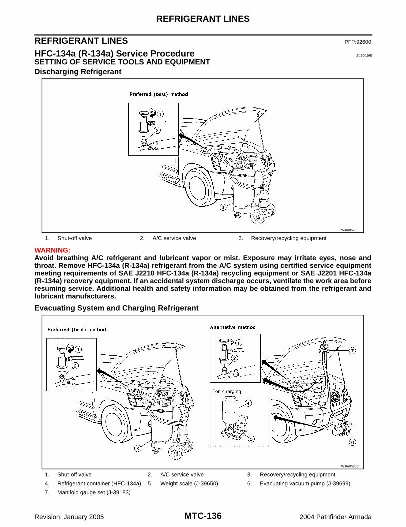
MTC-136
REFRIGERANT LINES
Revision: January 2005 2004 Pathfinder Armada
REFRIGERANT LINES PFP:92600
HFC-134a (R-134a) Service Procedure EJS0026E
SETTING OF SERVICE TOOLS AND EQUIPMENTDischarging Refrigerant
WARNING:Avoid breathing A/C refrigerant and lubricant vapor or mist. Exposure may irritate eyes, nose andthroat. Remove HFC-134a (R-134a) refrigerant from the A/C system using certified service equipmentmeeting requirements of SAE J2210 HFC-134a (R-134a) recycling equipment or SAE J2201 HFC-134a(R-134a) recovery equipment. If an accidental system discharge occurs, ventilate the work area beforeresuming service. Additional health and safety information may be obtained from the refrigerant andlubricant manufacturers.
Evacuating System and Charging Refrigerant
1. Shut-off valve 2. A/C service valve 3. Recovery/recycling equipment
WJIA0579E
1. Shut-off valve 2. A/C service valve 3. Recovery/recycling equipment
4. Refrigerant container (HFC-134a) 5. Weight scale (J-39650) 6. Evacuating vacuum pump (J-39699)
7. Manifold gauge set (J-39183)
WJIA0580E
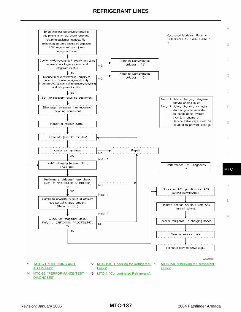
REFRIGERANT LINES
MTC-137
C
D
E
F
G
H
I
K
L
M
A
B
MTC
Revision: January 2005 2004 Pathfinder Armada
*1 MTC-21, "CHECKING AND ADJUSTING" .
*2 MTC-150, "Checking for Refrigerant Leaks".
*3 MTC-150, "Checking for Refrigerant Leaks".
*4 MTC-99, "PERFORMANCE TEST DIAGNOSES".
*5 MTC-4, "Contaminated Refrigerant".
WJIA0530E

MTC-138
REFRIGERANT LINES
Revision: January 2005 2004 Pathfinder Armada
Components EJS0026F
Front A/C Compressor and Condenser
WJIA1578E

REFRIGERANT LINES
MTC-139
C
D
E
F
G
H
I
K
L
M
A
B
MTC
Revision: January 2005 2004 Pathfinder Armada
Rear A/C
NOTE:Refer to MTC-6, "Precautions for Refrigerant Connection" .
1. High-pressure service valve 2. Grommet 3. High-pressure pipe
4. Refrigerant pressure sensor 5. Condenser 6. Compressor shaft seal
7. High-pressure flexible hose 8. Low-pressure flexible hose 9. Low-pressure service valve
10. Low-pressure pipe 11. Expansion valve (front) 12. Drain hose
WJIA0955E

MTC-140
REFRIGERANT LINES
Revision: January 2005 2004 Pathfinder Armada
Removal and Installation for Compressor EJS0026G
A/C Compressor Mounting
REMOVAL1. Discharge the refrigerant. Refer to MTC-136, "HFC-134a (R-134a) Service Procedure" .2. Remove the front right wheel and tire assembly. Refer to WT-6, "Rotation" .3. Remove the engine under cover and the splash shield using power tool.4. Remove the engine air cleaner and air ducts. Refer to EM-14, "AIR CLEANER AND AIR DUCT" .5. Remove the drive belt. Refer to EM-12, "DRIVE BELTS" .6. Disconnect the compressor electrical connector.7. Disconnect the high-pressure flexible hose and low-pressure flexible hose from the compressor.
CAUTION:Cap or wrap the joint of the pipe with suitable material such as vinyl tape to avoid the entry of air.
8. Remove the compressor bolts and nut using power tools.
WJIA0958E
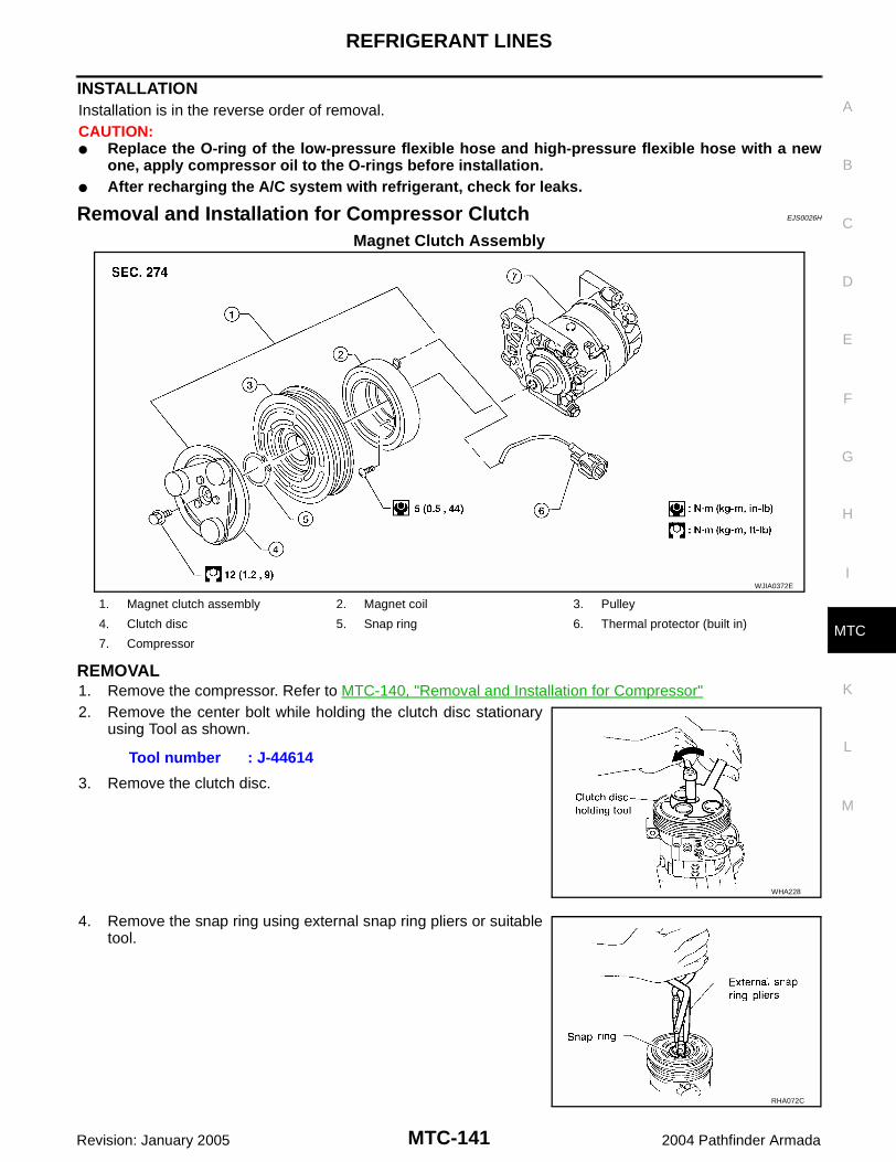
REFRIGERANT LINES
MTC-141
C
D
E
F
G
H
I
K
L
M
A
B
MTC
Revision: January 2005 2004 Pathfinder Armada
INSTALLATIONInstallation is in the reverse order of removal.CAUTION: Replace the O-ring of the low-pressure flexible hose and high-pressure flexible hose with a new
one, apply compressor oil to the O-rings before installation. After recharging the A/C system with refrigerant, check for leaks.
Removal and Installation for Compressor Clutch EJS0026H
Magnet Clutch Assembly
REMOVAL1. Remove the compressor. Refer to MTC-140, "Removal and Installation for Compressor"2. Remove the center bolt while holding the clutch disc stationary
using Tool as shown.
3. Remove the clutch disc.
4. Remove the snap ring using external snap ring pliers or suitabletool.
WJIA0372E
1. Magnet clutch assembly 2. Magnet coil 3. Pulley
4. Clutch disc 5. Snap ring 6. Thermal protector (built in)
7. Compressor
Tool number : J-44614
WHA228
RHA072C

MTC-142
REFRIGERANT LINES
Revision: January 2005 2004 Pathfinder Armada
5. Remove the pulley using Tool with a small adapter. Position thesmall adapter on the end of the drive shaft and the center of thepuller on the small adapter.CAUTION:To prevent deformation of the pulley groove, the pullerclaws should be hooked under the pulley groove and notinto the pulley groove.
6. Remove the magnet coil harness clip using a screwdriver,remove the three magnet coil fixing screws and remove themagnet coil.
INSPECTIONClutch DiscIf the contact surface shows signs of damage due to excessive heat,replace clutch disc and pulley.
PulleyCheck the appearance of the pulley assembly. If contact surface of pulley shows signs of excessive grooving,replace clutch disc and pulley. The contact surfaces of the pulley assembly should be cleaned with a suitablesolvent before reinstallation.
CoilCheck magnet coil for loose connections or any cracked insulation.
INSTALLATION1. Install the magnet coil.
CAUTION:Be sure to align the magnet coil pin with the hole in thecompressor front head.
LHA173
WHA212
WHA183
WHA213

REFRIGERANT LINES
MTC-143
C
D
E
F
G
H
I
K
L
M
A
B
MTC
Revision: January 2005 2004 Pathfinder Armada
2. Install the magnet coil harness clip using a screwdriver.3. Install the pulley assembly using Tool and a wrench, then install
the snap ring using snap ring pliers.
4. Install the clutch disc on the compressor shaft, together with theoriginal shim(s). Press the clutch disc down by hand.
5. Install the clutch pulley bolt using Tool, to prevent the clutch discfrom turning and tighten the bolt to specification. Refer to MTC-138, "Components" .
CAUTION:After tightening the clutch pulley bolt, check that the clutchpulley rotates smoothly.
6. Check the pulley clearance all the way around the clutch disc asshown.
7. If the specified clearance is not obtained, replace the adjustingspacer to readjust.
8. Connect the compressor electrical connector.9. Install the drive belt. Refer to EM-12, "DRIVE BELTS" .10. Install the engine under cover and the splash shield.
Tool number : — (J-38873-A)
WJIA0368E
WHA184
Tool number : J-44614
WHA229
Clutch disc-to-pulley clearance : 0.3 - 0.6 mm (0.012 - 0.024 in)
WHA194

MTC-144
REFRIGERANT LINES
Revision: January 2005 2004 Pathfinder Armada
BREAK-IN OPERATIONWhen replacing compressor clutch assembly, always conduct the break-in operation. This is done by engag-ing and disengaging the clutch about 30 times. Break-in operation raises the level of transmitted torque.
Removal and Installation for Low-pressure Flexible Hose EJS0026I
REMOVAL1. Remove the engine room cover using power tools.2. Remove the engine air cleaner and air ducts. Refer to EM-14, "AIR CLEANER AND AIR DUCT" .3. Remove the cowl top extension. Refer to EI-18, "COWL TOP" . 4. Discharge the refrigerant. Refer to MTC-136, "HFC-134a (R-134a) Service Procedure" .
CAUTION:Cap or wrap the joint of the pipe with suitable material such as vinyl tape to avoid the entry of air.
5. Remove the low-pressure flexible hose. Refer to MTC-138, "Components" .
INSTALLATIONInstallation is in the reverse order of removal.Refer to MTC-138, "Components" .CAUTION: Replace the O-ring of the low-pressure flexible hose with a new one, then apply compressor oil to
it when installing it. After charging refrigerant, check for leaks.
Removal and Installation for High-pressure Flexible Hose EJS0026J
REMOVAL1. Remove the engine under cover.2. Remove the engine air cleaner and air ducts. Refer to EM-14, "AIR CLEANER AND AIR DUCT"3. Discharge the refrigerant. Refer to MTC-136, "HFC-134a (R-134a) Service Procedure" .4. Remove the high-pressure flexible hose. Refer to MTC-138, "Components" .
CAUTION:Cap or wrap the joint of the pipe with suitable material such as vinyl tape to avoid the entry of air.
INSTALLATIONInstallation is in the reverse order of removal.Refer to MTC-138, "Components" .CAUTION: Replace the O-ring of the high-pressure flexible hose with a new one, then apply compressor oil to
it when installing it. After charging refrigerant, check for leaks.
Removal and Installation for High-pressure Pipe EJS0026K
REMOVAL1. Remove the cowl top extension. Refer to EI-18, "COWL TOP" . 2. Disconnect the battery negative cable.3. Reposition the IPDM E/R aside.4. Remove the front right wheel and tire assembly. Refer to WT-6, "Rotation" .5. Position aside the front floor insulator.6. Discharge the refrigerant. Refer to MTC-136, "HFC-134a (R-134a) Service Procedure" .7. Remove the low pressure pipe. Refer to MTC-145, "Removal and Installation for Low-pressure Pipe" .8. Remove the high-pressure pipe. Refer to MTC-138, "Components" .
CAUTION:Cap or wrap the joint of the pipe with suitable material such as vinyl tape to avoid the entry of air.
INSTALLATIONInstallation is in the reverse order of removal.Refer to MTC-138, "Components" .

REFRIGERANT LINES
MTC-145
C
D
E
F
G
H
I
K
L
M
A
B
MTC
Revision: January 2005 2004 Pathfinder Armada
CAUTION: Replace the O-ring of the high-pressure pipe with a new one, then apply compressor oil to it when
installing it. After charging refrigerant, check for leaks.
Removal and Installation for Low-pressure Pipe EJS0026L
REMOVAL1. Discharge the refrigerant. Refer to MTC-136, "HFC-134a (R-134a) Service Procedure" .2. Remove the cowl top and the cowl top extension. Refer to EI-18, "COWL TOP" .3. Remove the low-pressure pipe. Refer to MTC-138, "Components" .
CAUTION:Cap or wrap the joint of the pipes with suitable material such as vinyl tape to avoid the entry of air.
INSTALLATIONInstallation is in the reverse order of removal.Refer to MTC-138, "Components" .CAUTION: Replace the O-ring of the high/low-pressure pipe with a new one, then apply compressor oil to it
when installing it. After charging refrigerant, check for leaks.
Removal and Installation for Refrigerant Pressure Sensor EJS0026M
REMOVAL1. Discharge the refrigerant. Refer to MTC-136, "HFC-134a (R-134a) Service Procedure" .2. Disconnect the refrigerant pressure sensor electrical connector
and remove the refrigerant pressure sensor from the condenser.CAUTION:Be careful not to damage the condenser fins.
INSTALLATIONInstallation is in the reverse order of removal.Refer to MTC-138, "Components" .CAUTION: Be careful not to damage the condenser fins. Apply compressor oil to the O-ring of the refrigerant pressure sensor when installing it. After charging refrigerant, check for leaks.
Removal and Installation for Condenser EJS0026N
REMOVAL1. Discharge the refrigerant. Refer to MTC-136, "HFC-134a (R-134a) Service Procedure" .2. Remove the radiator. Refer to CO-10, "RADIATOR" .
CAUTION:Be careful not to damage the core surface of the condenser and the radiator.
3. Disconnect the high-pressure flexible hose and the high-pressure pipe from the condenser.CAUTION:Cap or wrap the joint of the pipe with suitable material such as vinyl tape to avoid the entry of air.
LJIA0145E

MTC-146
REFRIGERANT LINES
Revision: January 2005 2004 Pathfinder Armada
4. Disconnect the refrigerant pressure sensor connector. Remove the refrigerant pressure sensor from the condenser
as necessary.5. Lift the condenser out of the mounting grommets to remove the
condenser.
INSTALLATIONInstallation is in the reverse order of removal.Refer to MTC-138, "Components" .CAUTION: Replace the O-rings of the high-pressure pipe and the high-pressure flexible hose with new ones,
then apply compressor oil to them after installing them. After charging refrigerant, check for leaks. Replace the grommets as necessary.
LJIA0145E
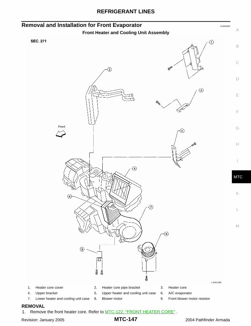
REFRIGERANT LINES
MTC-147
C
D
E
F
G
H
I
K
L
M
A
B
MTC
Revision: January 2005 2004 Pathfinder Armada
Removal and Installation for Front Evaporator EJS0026O
Front Heater and Cooling Unit Assembly
REMOVAL1. Remove the front heater core. Refer to MTC-122, "FRONT HEATER CORE" .
LJIA0138E
1. Heater core cover 2. Heater core pipe bracket 3. Heater core
4. Upper bracket 5. Upper heater and cooling unit case 6. A/C evaporator
7. Lower heater and cooling unit case 8. Blower motor 9. Front blower motor resistor
MTC-148
REFRIGERANT LINES
Revision: January 2005 2004 Pathfinder Armada
2. Remove the defroster mode door arm.3. Separate the heater core and cooling unit case.4. Remove the evaporator.
INSTALLATIONInstallation is in the reverse order of removal.CAUTION:Replace the O-rings on the low-pressure flexible hose and the high-pressure pipe with new ones.Apply compressor oil to the O-rings before installing them.
Removal and Installation for Rear Evaporator EJS0026P
Rear Heater and Cooling Unit Assembly
LJIA0135E
1. Front cover 2. Evaporator and heater core case 3. Evaporator
4. Side cover 5. Heater core 6. Rear blower motor
7. Blower motor case 8. Rear blower motor resistor

REFRIGERANT LINES
MTC-149
C
D
E
F
G
H
I
K
L
M
A
B
MTC
Revision: January 2005 2004 Pathfinder Armada
REMOVAL1. Remove the rear heater and cooling unit assembly from the vehicle. Refer to MTC-120, "REAR HEATER
AND COOLING UNIT ASSEMBLY" .2. Remove the rear blower motor.3. Remove the rear blower speed resistor.4. Remove the rear air mix door motor.5. Remove the rear duct and blend door assembly. Refer to MTC-
134, "DEFROSTER NOZZLE" .6. Disassemble the rear heater and cooling unit assembly to
remove the evaporator.
INSTALLATIONInstallation is in the reverse order of removal.CAUTION: Replace the O-rings on the rear A/C pipes with new ones. Apply compressor oil to the O-rings
before installing them. After charging refrigerant, check for leaks.
Removal and Installation for Front Expansion Valve EJS0026Q
REMOVAL1. Discharge the refrigerant. Refer to MTC-136, "HFC-134a (R-134a) Service Procedure" .2. Remove the front heater and cooling unit assembly. Refer to MTC-119, "FRONT HEATER AND COOLING
UNIT ASSEMBLY" .3. Remove the cooler grommet.4. Remove the expansion valve.
INSTALLATIONInstallation is in the reverse order of removal.
CAUTION: Replace the O-rings on the A/C refrigerant pipes with new ones, then apply compressor oil to them
when installing them. After charging refrigerant, check for leaks.
Removal and Installation for Rear Expansion Valve EJS0026R
REMOVAL1. Discharge the refrigerant. Refer to MTC-136, "HFC-134a (R-134a) Service Procedure" .2. Remove the rear RH interior side trim panel. Refer to EI-30, "Removal and Installation" .3. Disconnect the A/C refrigerant pipes from the expansion valve.
LJIA0021E
WJIA0582E
Expansion valve bolts : 4 N·m (0.41 kg-m, 35 in-lb)A/C refrigerant pipe to expansion valve bolt : Refer to MTC-138, "Components"
.
MTC-150
REFRIGERANT LINES
Revision: January 2005 2004 Pathfinder Armada
CAUTION:Cap or wrap the A/C refrigerant pipe ends with a suitable material such as vinyl tape to avoid theentry of air and contaminants.
4. Remove the expansion valve.
INSTALLATIONInstallation is in the reverse order of removal.
CAUTION: Replace the O-rings on the A/C refrigerant pipes with new ones, then apply compressor oil to them
when installing them. After charging refrigerant, check for leaks.
Checking for Refrigerant Leaks EJS0026S
Perform a visual inspection of all refrigeration parts, fittings, hoses and components for signs of A/C lubricantleakage, damage, and corrosion. Any A/C lubricant leakage may indicate an area of refrigerant leakage. Allowextra inspection time in these areas when using either an electronic refrigerant leak detector (J-41995) or fluo-rescent dye leak detector (J-42220).If any dye is observed using a fluorescent dye leak detector (J-42220), confirm the leak using a electronicrefrigerant leak detector (J-41995). It is possible that the dye is from a prior leak that was repaired and notproperly cleaned.When searching for leaks, do not stop when one leak is found but continue to check for additional leaks at allsystem components and connections.When searching for refrigerant leaks using an electronic refrigerant leak detector (J-41995), move the probealong the suspected leak area at 25 - 50 mm (1 - 2 in) per second and no further than 6 mm (1/4 in) from thecomponent.CAUTION:Moving the electronic refrigerant leak detector probe slower and closer to the suspected leak area willimprove the chances of finding a leak.
Checking System for Leaks Using the Fluorescent Dye Leak Detector EJS0026T
1. Check the A/C system for leaks using the fluorescent dye leak detector (and safety goggles) (J-42220) ina low sunlight area (area without windows preferable). Illuminate all components, fittings and lines. Thedye will appear as a bright green/yellow area at the point of leakage. Fluorescent dye observed at theevaporator drain opening indicates an evaporator core assembly leak (tubes, core or expansion valve).
2. If the suspected area is difficult to see, use an adjustable mirror or wipe the area with a clean shop rag orcloth, then inspect the shop rag or cloth with the fluorescent dye leak detector (J-42220) for dye residue.
3. After the leak is repaired, remove any residual dye using dye cleaner (J-43872) to prevent future misdiag-nosis.
4. Perform a system performance check and then verify the leak repair using a electronic refrigerant leakdetector (J-41995).NOTE: Other gases in the work area or substances on the A/C components, for example, anti-freeze, wind-
shield washer fluid, solvents and lubricants, may falsely trigger the leak detector. Make sure the sur-faces to be checked are clean.
Clean with a dry cloth or blow off with shop air. Do not allow the sensor tip of the electronic refrigerant leak detector (J-41995) to contact with any sub-
stance. This can also cause false readings and may damage the detector.
Dye Injection EJS0026U
NOTE:This procedure is only necessary when recharging the system or when the compressor has seized and mustbe replaced.
1. Check the A/C system static (at rest) pressure. Pressure must be at least 345 kPa (3.52 kg/cm2 , 50 psi).
Expansion valve bolts : 4 N·m (0.41 kg-m, 35 in-lb)A/C refrigerant pipe to expansion valve bolt : Refer to MTC-138, "Components"
.

REFRIGERANT LINES
MTC-151
C
D
E
F
G
H
I
K
L
M
A
B
MTC
Revision: January 2005 2004 Pathfinder Armada
2. Pour one bottle 7.4 cc (1/4 ounce) of the HFC-134a (R-134a) fluorescent leak detection dye (J-41447) intothe HFC-134a (R-134a) dye injector (J-41459).CAUTION:If repairing the A/C system or replacing a component, pour the HFC-134a (R-134a) fluorescent leakdetection dye (J-41447) directly into the open system connection and proceed with the serviceprocedures.
3. Connect the injector tool (J-41459) to the low-pressure service valve.4. Start the engine and switch the A/C system ON.5. When the A/C system is operating (compressor running), inject one bottle 7.4 cc (1/4 ounce) of HFC-134a
(R-134a) fluorescent leak detection dye (J-41447) through the low-pressure service valve using HFC-134a (R-134a) dye injector (J-41459). Refer to the manufacturer's operating instructions.
6. With the engine still running, disconnect the HFC-134a (R-134a) dye injector (J-41459) from the low-pres-sure service valve.
7. Operate the A/C system for a minimum of 20 minutes to mix the HFC-134a (R-134a) fluorescent leakdetection dye (J-41447) with the A/C system oil. Depending on the leak size, operating conditions andlocation of the leak, it may take from minutes to days for the HFC-134a (R-134a) fluorescent leak detec-tion dye to penetrate an A/C system leak and become visible.
Electronic Refrigerant Leak Detector EJS0026V
PRECAUTIONS FOR HANDLING LEAK DETECTORNOTE:When performing a refrigerant leak check, use a electronic refrigerant leak detector (J-41995) or equivalent.Ensure that the electronic refrigerant leak detector (J-41995) is calibrated and set properly according to themanufacturer's operating instructions.The electronic refrigerant leak detector (J-41995) is a delicatedevice. To use the leak detector properly, read the manufacturer'soperating instructions and perform any specified maintenance.
1. Position the probe approximately 5 mm (3/16 in) away from thepoint to be checked as shown.
AHA281A
SHA707EA

MTC-152
REFRIGERANT LINES
Revision: January 2005 2004 Pathfinder Armada
2. When checking for leaks, circle each fitting completely with theprobe as shown.
3. Move the probe along each component at a speed of approxi-mately 25 - 50 mm (1 - 2 in)/second as shown.
CHECKING PROCEDURENOTE:To prevent inaccurate or false readings, make sure there is no refrigerant vapor, shop chemicals, or cigarettesmoke in the vicinity of the vehicle. Perform the leak test in a calm area (low air/wind movement) so that theleaking refrigerant is not dispersed.1. Turn the engine OFF.2. Connect the manifold gauge set (J-39183-C) to the A/C service ports. Refer to MTC-136, "SETTING OF
SERVICE TOOLS AND EQUIPMENT" .
3. Check if the A/C refrigerant pressure is at least 345 kPa (3.52 kg/cm2 , 50 psi) above a temperature of16°C (61°F). If less than specification, recover/evacuate and recharge the system with the specifiedamount of refrigerant. Refer to MTC-136, "HFC-134a (R-134a) Service Procedure" .NOTE:At temperatures below 16°C (61°F), leaks may not be detected since the system may not reach 345 kPa(3.52 kg/cm2 , 50 psi) pressure.
4. Perform the leak test from the high-pressure side (front A/C compressor discharge “a” to evaporator inlet“f” or rear piping connection “l”) to the low-pressure side (front A/C evaporator drain hose “g” to shaft seal“k” and rear A/C evaporator drain hose “o” to piping connection “r”). Refer to MTC-138, "Components" .Clean the component to be checked and carefully move the electronic refrigerant leak detector probecompletely around the following connections and components. Check the compressor shaft seal Check the high and low-pressure pipe and hose fittings, relief valve, and compressor shaft seal Check the liquid tank Check the refrigerant pressure sensor Check all around the service valves. Check that the service valve caps are screwed tightly on the ser-
vice valves (to prevent leaks).NOTE:After removing manifold gauge set (J-39183-C) from the service valves, wipe any residue from the ser-vice valves to prevent any false readings by the electronic refrigerant leak detector (J-41995).
EvaporatorWith engine OFF, turn blower fan on “High” for at least 15 seconds to dissipate any refrigerant trace inthe heater and cooling unit assembly. Wait a minimum of 10 minutes accumulation time (refer to themanufacturer's recommended procedure for actual wait time) before inserting the electronic refrigerantleak detector probe into the heater and cooling unit assembly drain hose.
SHA706E
SHA708EA

REFRIGERANT LINES
MTC-153
C
D
E
F
G
H
I
K
L
M
A
B
MTC
Revision: January 2005 2004 Pathfinder Armada
NOTE:Keep the probe inserted for at least 10 seconds. Use caution not to contaminate the probe tip withwater or dirt that may be in the drain hose.
5. If a leak is detected, verify at least once by blowing compressed air into the area of the suspected leak,then repeat the leak check.
6. Do not stop when one leak is found. Continue to check for additional leaks at all system components andconnections.
7. If no leaks are found, perform steps 8 - 11.8. Start the engine.9. Set the heater A/C controls as follows:
NOTE:For the automatic system, turn OFF the automatic controls and set the heater A/C controls manually.
a. A/C switch to ONb. Air flow to VENT modec. Intake position to RECIRCULATION moded. Temperature to MAX colde. Blower speed to HIGH
10. Run the engine at 1,500 rpm for at least 2 minutes.11. Turn the engine OFF and perform the leak check again following
steps 4 through 6 above.Refrigerant leaks should be checked immediately after turningthe engine OFF. Begin with the leak detector at the compressor.The pressure on the high pressure side will gradually drop afterthe refrigerant circulation stops and pressure on the low pres-sure side will gradually rise, as shown in the graph. Some leaksare more easily detected when the pressure is high.
12. Before connecting the recovery/recycling equipment to the vehicle, check the recovery/recycling equip-ment gauges. No refrigerant pressure should be displayed. If pressure is displayed, recover the refriger-ant from the equipment lines and then check the refrigerant purity.
13. Confirm refrigerant purity in supply tank using recovery/recycling equipment and refrigerant identifierequipment (J-41810-NI).
14. Confirm the refrigerant purity in the vehicle's A/C system using recovery/recycling equipment and refriger-ant identifier equipment (J-41810-NI).
15. Discharge the A/C system using recovery/recycling equipment. Repair the leaking fitting or component asnecessary.
16. Evacuate and recharge the A/C system and perform the leak test to confirm that there are no refrigerantleaks.
17. Conduct the Operational Check to ensure system works properly. Refer to MTC-49, "Operational Check(Front)" .
SHA839E

MTC-154
SERVICE DATA AND SPECIFICATIONS (SDS)
Revision: January 2005 2004 Pathfinder Armada
SERVICE DATA AND SPECIFICATIONS (SDS) PFP:00030
Service Data and Specifications (SDS) EJS0026W
COMPRESSOR
LUBRICANT
REFRIGERANT
ENGINE IDLING SPEEDRefer to EC-31, "Idle Speed and Ignition Timing Check" .
BELT TENSIONRefer to EM-12, "Tension Adjustment" .
Make ZEXEL VALEO CLIMATE CONTROL
Model DKS-17D
Type Swash plate
Displacement 175.5 cm3 (10.7 in3 ) / rev
Cylinder bore × stroke 30.5 mm (1.20 in) x 24.0 mm (0.94 in)
Direction of rotation Clockwise (viewed from drive end)
Drive belt Poly V
Name NISSAN A/C System Lubricant Type S (DH-PS)
Part number KLH00-PAGS0
Capacity Total in system 290 m (9.8 US fl oz, 10.2 lmp fl oz)
Type HFC-134a (R-134a)
Capacity 1.08 ± 0.05 kg (2.38 ± 0.11 lb)