section j – level 1 ttm handbook
TRANSCRIPT
Traffic Control Devices Manual Part 8
Code of practice for temporary traffic management (CoPTTM) Manual number: SP/M/010
Section J – Level 1 TTM handbook
© NZ Transport Agency
www.nzta.govt.nz
Fourth edition, Amendment 3 of Code of practice for temporary traffic management
Date of issue: 1 October 2014
Effective date: 1 December 2014
ISBN 978-0-478-40772-3 (print)
ISBN 978-0-478-40773-0 (online)
Copyright information
This publication is copyright © NZ Transport Agency. Material in it may be reproduced for personal or in-house use without formal permission or charge, provided suitable acknowledgement is made to this publication and the NZ Transport Agency (NZTA) as the source. Requests and enquiries about the reproduction of material in this publication for any other purpose should be made to: NZ Transport Agency Private Bag 6995 Wellington 6141
The permission to reproduce material in this publication does not extend to any material for which the copyright is identified as being held by a third party. Authorisation to reproduce material belonging to a third party must be obtained from the copyright holder(s) concerned.
Disclaimer
The NZTA has endeavoured to ensure material in this document is technically accurate and reflects legal requirements. However, the document does not override governing legislation. The NZTA and its employees and agents involved in the preparation and publication of this document do not accept liability for any consequences arising from the use of this document. Users of this document should apply and rely upon their own skill and judgment, and should not rely on the manual's contents in isolation from other sources of advice and information. In applying their own skill and judgment, the standards of safety and serviceability explicitly required or implied by this manual shall not be reduced. If the user is unsure whether the material is correct, they should make direct reference to the relevant legislation or regulations and contact the NZTA.
More information
Published 2013
ISBN 978-0-478-40772-3 (print)
ISBN 978-0-478-40773-0 (online)
NZ Transport Agency
Contents Glossary of terms ........................................................................................................................ iv Introduction to level 1 TTM handbook........................................................................................ 1
Sections of CoPTTM .................................................................................................................................. 1 Overview of level 1 TTM handbook ...................................................................................................... 2 Key aspects .................................................................................................................................................. 3
Section A - Introduction and general ......................................................................................... 4 About CoPTTM (A1) ................................................................................................................................ 4 Principles (A3) ........................................................................................................................................... 4 Levels of temporary traffic management (TTM) (A4) .................................................................... 4 Powers and responsibilities (A5) ...........................................................................................................5 Training (A6) .............................................................................................................................................. 11 Traffic management plans (A7) ........................................................................................................... 12 Temporary traffic management (TTM) safety audit procedures (A8) ...................................... 15
Section B - Equipment ................................................................................................................ 16 Signs including stands and supports (B1) ........................................................................................... 16 Delineation devices (B2) ....................................................................................................................... 35 High visibility garments (B3) ................................................................................................................ 37 Logos, names and trademarks (B4).................................................................................................... 38 Portable traffic signals (B5) .................................................................................................................. 39 Safety fences (B6) .................................................................................................................................. 40 Horizontal arrow boards (B8.3) .......................................................................................................... 40 Mobile variable message sign (B10) .................................................................................................... 41 Temporary road safety barriers (B12) ................................................................................................. 41 Temporary speed humps (B13) ............................................................................................................ 41 Warning systems (B14) .......................................................................................................................... 41
Section C - Static operations ................................................................................................... 42 Worksite layout (C2) ............................................................................................................................. 42 Signs and worksite zones (C3) ............................................................................................................ 49 Temporary speed limit – TSL (C4)...................................................................................................... 52 Delineation devices (C5) ....................................................................................................................... 56 Safety zones (C6) .................................................................................................................................... 57 Tapers (C7) ............................................................................................................................................... 58 Shoulder and lane closures (C8) ......................................................................................................... 60 Road closures and detours (C9) .......................................................................................................... 65 Positive traffic management (C10) ..................................................................................................... 66 Temporary traffic management (TTM) installation, management and removal (C11) ......... 72 Unattended worksites and activity at night (C12) .......................................................................... 74 Pedestrians and cyclists (C13) ............................................................................................................. 76 Work vehicles, equipment and materials (C14) .............................................................................. 79 Worksite access (C15) ...........................................................................................................................80
Traffic control devices manual part 8 CoPTTM Section J - Page ii 4th edition, October 2014

Managing traffic queues (C16) ............................................................................................................. 81 Equipment maintenance standards (C19) ........................................................................................ 82
Section D - Mobile operations ................................................................................................. 88 General (D1) ............................................................................................................................................. 88 Work vehicles (D2) ................................................................................................................................ 94 Pilot vehicles (D3) .................................................................................................................................. 94 Shadow vehicles (D4) ........................................................................................................................... 96 Mobile closures operational requirements (D5) ............................................................................ 96 Semi-static closures (D6) ..................................................................................................................... 99 Special mobile operations (D7) .......................................................................................................... 101
List of appendices .................................................................................................................... 104 Appendix a TSL decision matrix worksheet ................................................................................... 105 Appendix B1 level 1 & LV layout distances table ........................................................................... 106 Appendix B2 level LV layout distances table ..................................................................................107 Appendix C Short TMP ........................................................................................................................ 108 Appendix D Full TMP ............................................................................................................................. 111 Appendix E Checking process GTMPs ............................................................................................ 120 Appendix F On-site record ................................................................................................................... 121 Appendix G Site condition rating form – Full audit ........................................................................ 122 Appendix H Site condition rating form – Short audit .................................................................... 123 Appendix I Notice of non-conformance ........................................................................................... 125 Appendix J Application for STMS delegated authority ................................................................ 126
Traffic control devices manual part 8 CoPTTM Section J - Page iii 4th edition, October 2014

NZ Transport Agency
Glossary of terms A list of terms used in this document having specialised meanings or interpretation in the NZ Transport Agency’s Code of practice for temporary traffic management (CoPTTM).
Annual average daily traffic (AADT)
The average volume of traffic using a road over the year. The AADT is shown as vehicles per day (vpd).
Clear sight distance (CSD)
CSD is used for mobile operations and is the distance a road user can clearly see along the road with no obstructions.
Code of practice for temporary traffic management (CoPTTM)
The NZ Transport Agency’s Traffic control devices manual part 8 Code of practice for temporary traffic management describes best practice for the safe and efficient management and operation of temporary traffic management (TTM) on all roads in New Zealand and is mandatory on state highways.
Engineering exception decision (EED)
A written decision that varies minimum CoPTTM requirements. It is agreed between the contractor and the RCA.
Manual traffic controller (MTC)
A person controlling the flow of traffic in a single lane past a closure with the use of stop/go paddles – RP4/RP41 (TW-33).
Multi-lane roads For a driver, means a one-way road, or a two-way road, with two or more marked lanes (except bicycle lanes) that are:
• on the side of the dividing line or median strip where the driver is driving • for the use of vehicles travelling in the same direction.
NZ Transport Agency (NZTA)
The government agency in New Zealand responsible for CoPTTM.
Road controlling authority (RCA)
The RCA is the authority, body or person who has control of the roading network (eg for state highways the RCA is NZTA).
Road environment constraints
A road environment constraint can be a short urban block, access to commercial or residential premise and similar items which may interfere with standard taper length or sign spacings.
Road reserve The area of land between the legal boundaries, usually fence line to fence line and including any safety run-off areas, which is dedicated to allow the passage of road users. The road reserve also includes an airspace of six metres directly above the road surface. The terms road and road reserve have the same meaning in the NZ Transport Agency’s Traffic control devices manual.
Road user Any user of the road, including motor vehicle drivers, motorcyclists, pedestrians and cyclists.
Safety zones A safety zone is a three-dimensional space extending to the front and back, to the sides and above a working space. This space also includes the areas within the coned tapers although these are not included in the safety zone dimensions.
Site traffic management supervisor (STMS)
An NZ Transport Agency (NZTA) qualified person who has specific responsibility for documentation, and management of temporary traffic management (TTM).
Traffic control devices manual part 8 CoPTTM Section J - Page iv 4th edition, October 2014
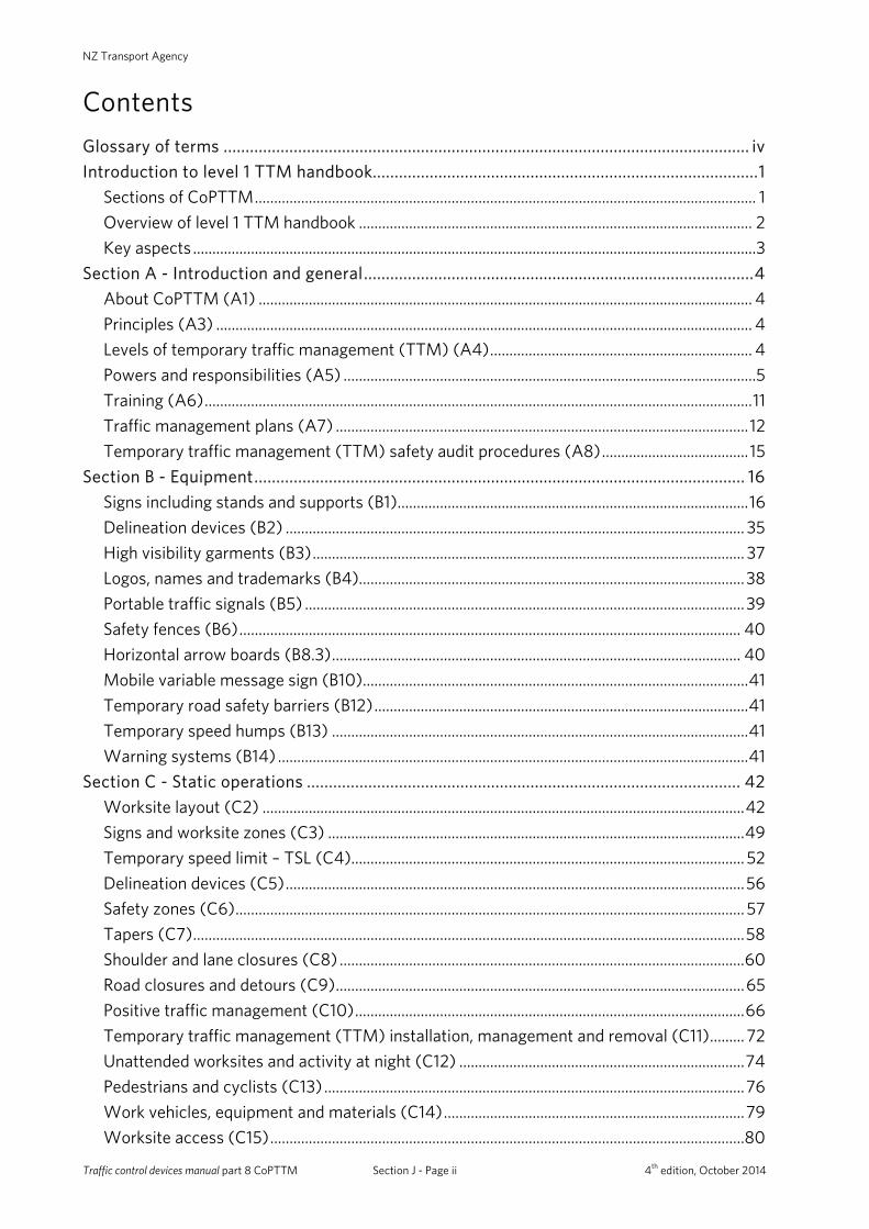
TCD Rule Land Transport Rule: Traffic Control Devices 2004, including any subsequent amendments.
Temporary speed limit (TSL)
A speed limit that is in force for a period of less than six months and is set under the Land Transport Rule: Setting of Speed Limits 2003 by the RCA.
Temporary traffic management (TTM)
The process of managing road users through or past a closure in a safe manner with minimal delay and inconvenience.
Traffic controller (TC) An NZ Transport Agency (NZTA) qualified person who has specific responsibility to manage a worksite on a level LV and level 1 road.
Traffic management coordinator (TMC)
A person, or position, in an organisation that has the delegated authority from a road controlling authority (RCA) to approve traffic management plans (TMPs), coordinate temporary traffic management (TTM) and, where appropriate for local roads, to delegate power to approve TMPs to others.
Traffic management diagram (TMD)
The TMD is a traffic management diagram within, and forms part of, the TMP. A TMP may have more than one TMD included as part of it.
Traffic management plan (TMP)
A document describing the design, implementation, maintenance and removal of temporary traffic management (TTM) while the associated activity is being carried out within the road reserve or adjacent to and affecting the road reserve.
Temporary speed limit (TSL)
A speed limit that is in force for a period of less than six months and is set under the Land Transport Rule: Setting of Speed Limits 2003 by the RCA.
Temporary traffic management (TTM)
The process of managing road users through or past a closure in a safe manner with minimal delay and inconvenience.
WorkSafe NZ WorkSafe NZ is New Zealand’s workplace health and safety regulator. It works to reduce work-related death and injury rates, and support employers and employees in productive work.
Traffic control devices manual part 8 CoPTTM Section J - Page v 4th edition, October 2014

NZ Transport Agency Introduction to level 1 TTM handbook
Introduction to level 1 TTM handbook
Sections of CoPTTM This level 1 TTM handbook forms section J of the Code of Practice for Temporary Traffic Management (CoPTTM). It only provides a summary of the key elements of the CoPTTM. It also includes additional diagrams covering a wider range of situations than those included in section F. This handbook is designed to be used as a support to training and an onsite reference document.
It is not intended to be used in place of, nor supersede, the CoPTTM.
The following sections are summarised in this handbook:
Section Title
Section A Introduction and general
Section B Equipment
Section C Static operations
Section D Mobile operations
Section E Standard forms and descriptions
Section F Level LV and level 1 layout drawings
Traffic control devices manual part 8 CoPTTM Section J - Page 1 4th edition, October 2014
Introduction to level 1 TTM handbook
Overview of level 1 TTM handbook This Level 1 TTM handbook is made available on the basis that all users:
• are conversant with CoPTTM and hold current qualification as prescribed by CoPTTM • comply with the requirements of:
o CoPTTM o Health and Safety in Employment Act and Regulations o TCD Rule
• comply with all legislation relevant to the works • keep abreast of all revisions of CoPTTM and relevant legislation • comply with requirements of the Road Controlling Authority • exercise sound judgment.
The fundamentals CoPTTM must be applied to any activity that varies the normal operating conditions of the road reserve.
All activities must be managed in terms of an approved traffic management plan (TMP).
Temporary traffic management (TTM) must be installed before any work activity commences.
Worksites must be under the control of a Site Traffic Management Supervisor (STMS) at all times. For attended worksites, the STMS may delegate site control to a Traffic Controller (TC).
Traffic control devices manual part 8 CoPTTM Section J - Page 2 4th edition, October 2014
NZ Transport Agency Introduction to level 1 TTM handbook
Key aspects TTM must:
• provide for all affected parties including heavy vehicles, cars, cyclists, pedestrians, property owners and adjoining businesses
• accommodate special demands imposed by schools, emergency services, rail/rail crossings, airports, ports, utilities, industry, recreational, facilities, special events, holidays etc
• accommodate: o all work phases o site specific volumes and traffic character o day/night/poor light etc o attended/ unattended work sites o weather
• comply with specific Road Controlling Authority requirements • provide a contingency plan • ensure all persons working on or visiting the site are fully briefed on site safety
requirements • provide for regular monitoring of the work site.
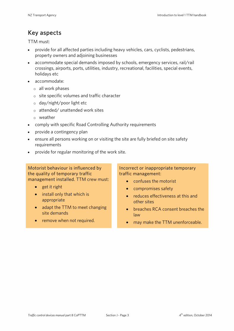
Motorist behaviour is influenced by the quality of temporary traffic management installed. TTM crew must:
• get it right • install only that which is
appropriate • adapt the TTM to meet changing
site demands • remove when not required.
Incorrect or inappropriate temporary traffic management:
• confuses the motorist • compromises safety • reduces effectiveness at this and
other sites • breaches RCA consent breaches the
law • may make the TTM unenforceable.
Traffic control devices manual part 8 CoPTTM Section J - Page 3 4th edition, October 2014
Summary of section A - Introduction and general
Section A - Introduction and general
About CoPTTM (A1)
Availability of CoPTTM (A1.2) CoPTTM is available in two forms:
1. Electronic format: CoPTTM is available as a PDF on the NZTA’s website.
2. Printed format: A complete copy or specific sections of CoPTTM are available to order from the NZTA’s website (www.nzta.govt.nz/resources/code-temp-traffic-management/copttm.html).
Principles (A3) To ensure safe and efficient TTM, CoPTTM is based on the following fundamental principles: • TTM must be consistent throughout New Zealand • there must be a TMP for all activities • safety for road workers and users must be an integral part of all activities carried out • clear and positive guidance must be provided for road users • activities must be planned so as to cause as little disruption to road users as possible
without compromising safety.
Levels of temporary traffic management (TTM) (A4)
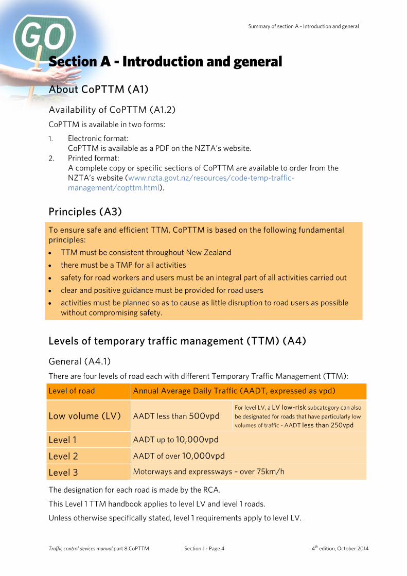
General (A4.1) There are four levels of road each with different Temporary Traffic Management (TTM):
Level of road Annual Average Daily Traffic (AADT, expressed as vpd)
Low volume (LV) AADT less than 500vpd For level LV, a LV low-risk subcategory can also be designated for roads that have particularly low volumes of traffic - AADT less than 250vpd
Level 1 AADT up to 10,000vpd
Level 2 AADT of over 10,000vpd
Level 3 Motorways and expressways – over 75km/h
The designation for each road is made by the RCA.
This Level 1 TTM handbook applies to level LV and level 1 roads.
Unless otherwise specifically stated, level 1 requirements apply to level LV.
Traffic control devices manual part 8 CoPTTM Section J - Page 4 4th edition, October 2014
NZ Transport Agency Summary of section A - Introduction and general
Powers and responsibilities (A5)
Road controlling authority (A5.3)
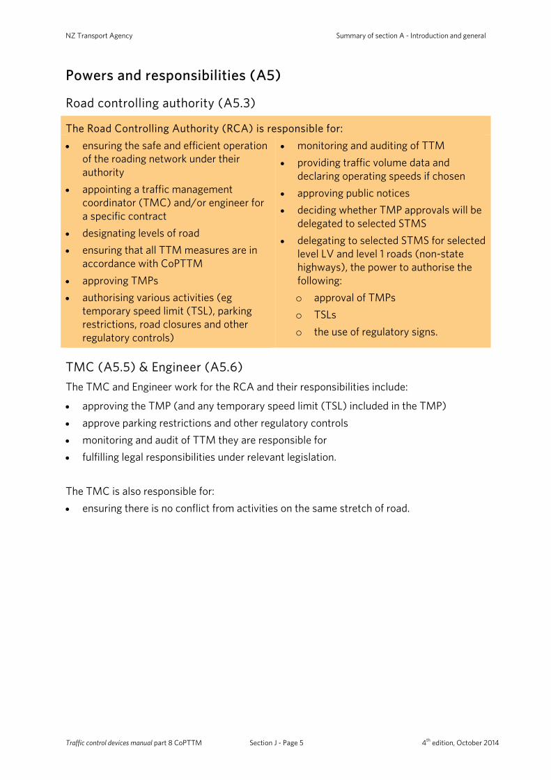
The Road Controlling Authority (RCA) is responsible for:
• ensuring the safe and efficient operation of the roading network under their authority
• appointing a traffic management coordinator (TMC) and/or engineer for a specific contract
• designating levels of road • ensuring that all TTM measures are in
accordance with CoPTTM • approving TMPs • authorising various activities (eg
temporary speed limit (TSL), parking restrictions, road closures and other regulatory controls)
• monitoring and auditing of TTM • providing traffic volume data and
declaring operating speeds if chosen • approving public notices • deciding whether TMP approvals will be
delegated to selected STMS • delegating to selected STMS for selected
level LV and level 1 roads (non-state highways), the power to authorise the following: o approval of TMPs o TSLs o the use of regulatory signs.
TMC (A5.5) & Engineer (A5.6) The TMC and Engineer work for the RCA and their responsibilities include:
• approving the TMP (and any temporary speed limit (TSL) included in the TMP) • approve parking restrictions and other regulatory controls • monitoring and audit of TTM they are responsible for • fulfilling legal responsibilities under relevant legislation. The TMC is also responsible for: • ensuring there is no conflict from activities on the same stretch of road.
Traffic control devices manual part 8 CoPTTM Section J - Page 5 4th edition, October 2014
Summary of section A - Introduction and general
Contractors (A5.7) Contractors are responsible for: • ensuring they have the authorisation of the RCA to carry out work or other activity in
the road reserve or affecting the road reserve • ensuring those preparing TMPs are trained STMS • preparing accurate TMPs that reflect the worksite conditions, in accordance with
CoPTTM and any contractual requirements or RCA authorisation conditions • ensuring they have an approved and accepted TMP before starting any work • obtaining approval and timings for occupation of the worksite, from the TMC prior to
commencing work • implementing approved TMPs • operating in terms of the traffic regulations and the requirements of The official New
Zealand road code • ensuring that all TSLs have been authorised by the RCA (or person with delegated
authority) • storing any TTM equipment or plant not in immediate use, off the carriageway and in
accordance with C14.1.4 Parking and storage of vehicles, plant and materials • the appointment of a suitably trained STMS and/or traffic controller (TC), and staff for
each worksite - recording details of inspections/audits of TTM measures • ensuring that the STMS is supported in matters of safety • suspending any STMS issued with two notices of non-conformance within a three-
month period from TTM supervision duties • reporting on crashes at worksites to TMC within 24 hours (definition of a crash is
provided in subsection A5.7.3 Definition of a crash).
Definition of a crash
A crash is defined as any incident involving a road user, resulting in damage to any installed TTM equipment, vehicles, plant or injury to a person. Any crash resulting in a serious harm accident must be reported to the WorkSafe NZ as soon as the accident becomes known.
The contractor must record all crashes at worksites and, within 24 hours of any crash, brief the engineer and/or the RCA on the details of the crash, including the following: • a copy of the signed and approved TMP for the worksite • details of the incident including a diagram showing the layout of the worksite at the
time of the crash. The diagram must also show any relevant crash details such as vehicle travel paths, skid marks, etc
• photographs of the crash site. Minor incidents, such as one or two cones being struck, do not need to be recorded unless there appears to have been potential for a serious incident to have occurred.
Traffic control devices manual part 8 CoPTTM Section J - Page 6 4th edition, October 2014
NZ Transport Agency Summary of section A - Introduction and general
Site Traffic Management Supervisor (A5.8) The person in charge of TTM at a level LV and level 1 worksite is the Site Traffic Management Supervisor (STMS). The STMS may delegate control of the site to a TC. Note: A Level 1 qualified person must not have any TTM responsible position for any Level 2 or 3 Temporary Traffic Management.
The STMS has the authority to:
• postpone, cancel or modify operations when safety is threatened • permit visitor entry to the worksite • order people off the worksite for issues of non-compliance or safety.
Note: Where a visitor is wearing a standard high visibility garment this will be enough to enter the worksite but not the working space. Where other equipment such as steel cap footwear, helmets or fire retardant garments are required in the working space, the visitor may be denied entry to the working space.
The STMS cannot amend TSLs without delegated authority or prior approval of the RCA or the engineer. The STMS’ general responsibilities are: • ensure there is a copy of the approved TMP available on-site at all times when the
worksite is attended and that this is available for inspection • ensure TMP is appropriate to the worksite. Where the TMP is not suitable, halt
proceedings until the necessary actions have been taken ensure contingency plans are implemented
• arrange on-site toolbox meetings at the start of each set-up, on a regular basis (eg daily) and at each change of a TTM measure. Use the approved TMP to explain: o the worksite hazards o site driving/parking requirements o the method of entering/leaving the worksite
• ensure all personnel entering the worksite are briefed on the safety hazards and the safety procedures to be followed. Visitors are to sign confirming they have understood the briefing
• ensure all personnel and visitors on-site are wearing compliant high-visibility clothing • train MTC on how to carry out their function • record and notify the RCA or engineer as appropriate of all crashes at the worksite and
any complaints about the TTM • record and inform the RCA or engineer immediately of any significant modifications to
TTM • brief the TC on the TTM requirements of the worksite before handing control of the
worksite to the TC. Briefing must be confirmed in writing to acknowledge the handover • be contacted by mobile phone or two-way radio at all times • ensure traffic is monitored for queuing and delays • ensure worksite inspections are completed at least two hourly
Traffic control devices manual part 8 CoPTTM Section J - Page 7 4th edition, October 2014
Summary of section A - Introduction and general
• ensure that all corrective action detailed in a notice of non-conformance is undertaken within the required time frame
• ensure that persons on the worksite operate in terms of the traffic regulations and the requirements of The official New Zealand road code
• ensure any TTM changes required by the New Zealand Police, WorkSafe NZ, RCA or engineer are made immediately and documented on the TMP. The TMC is to be informed within 24 hours.
On level LV and level 1 roads the STMS may undertake other worker roles in addition to their STMS duties. The STMS role must take priority. The STMS, or a TC, to whom the STMS has delegated worksite control, must be on-site at all times on an attended worksite. The STMS can manage up to six attended worksites. The STMS travel time from each worksite is:
Level of road Attended worksite delegated to a TC Unattended worksite
Level 1 30 minutes 60 minutes
Level LV 60 minutes 120 minutes
Any attended worksite delegated to a TC must be inspected by the STMS on a daily basis (or for activities that move from worksite to worksite within a day the STMS must inspect one worksite each day). These worksite inspections must be documented by the STMS. The STMS may manage all active worksites for a capital project at any one time subject to remaining within 30 minutes of all sites. A TC, properly briefed by the STMS in charge, must be in control of each worksite when the STMS is absent. For mobile operations and short-term operations, which do not require more than five personnel in total to satisfactorily undertake the work, the STMS may also undertake other aspects of the work. Note: The STMS does not have to undertake a worksite inspection of an activity being controlled by a TC where that activity is an inspection as defined in section D. For inspection activities, as defined in section D, the STMS must be immediately contactable but does not have to be within 30 minutes travel time of the worksite.
Traffic control devices manual part 8 CoPTTM Section J - Page 8 4th edition, October 2014
NZ Transport Agency Summary of section A - Introduction and general
Site safety briefings (A5.8.6) All persons involved with the activities must be briefed/inducted by the STMS and/or TC, and have this documented on the site records.
Use the approved TMP to explain:
• identified hazards • the TTM requirements for the
worksite • safety zone requirements and limits.
Briefings are to be completed:
• at the start of each set-up • on a regular basis (eg daily) • at each new phase of the works.
All people arriving on-site must receive a worksite induction before proceeding around the worksite. The approved TMP is used to explain:
• the worksite hazards • site driving and parking requirements • the method of entering and leaving the worksite. The STMS must have with them their NZTA warrant card (or suitable certified documentation as evidence of qualification). Where there are three or more personnel on-site, the STMS must wear the STMS garment (where less than three personnel on site, the STMS may wear the fluorescent red-orange high-visibility garment).
Traffic controller (A5.9)
When delegated control of a worksite, the TC has the authority to:
• Postpone, cancel or modify operations when safety is threatened • Permit visitor entry to the worksite • Order people off the worksite for issues of non-compliance or safety.
Note: Where a visitor is wearing a standard high visibility garment this will be enough to enter the worksite but not the working space. Where other equipment such as steel cap footwear, helmets or fire retardant garments are required in the working space, the visitor may be denied entry to the working space.
For level LV and level 1 roads a TC may take the role of an STMS and set up, maintain, alter and remove TTM for the worksite under the following conditions: • there is an approved TMP for the worksite • the STMS must brief the TC in charge of the worksite on the TTM requirements • the STMS inspects the worksite on a daily basis (or for activities that move from
worksite to worksite within a day, the STMS must inspect one worksite each day). ALL of the above actions must be documented by the STMS. The TC may also perform other duties (eg foreman, grader driver) however TTM responsibilities must take priority.
Traffic control devices manual part 8 CoPTTM Section J - Page 9 4th edition, October 2014
Summary of section A - Introduction and general
General responsibilities of a TC (A5.9.3) The general responsibilities of the appointed TC for a worksite are to: • ensure TMP is appropriate to the worksite. Where the TMP is not suitable, halt
proceedings until the necessary actions have been taken • carry out on-site toolbox meetings at the start of each set-up, on a regular basis (eg
daily) and at each change of a TTM measure. Use the approved TMP to explain: o the worksite hazards o site driving/parking requirements o the method of entering/leaving the worksite
• keep a record of induction sessions held • ensure all personnel and visitors on-site are wearing compliant high-visibility clothing
and any other safety equipment required by the activity • ensure traffic is monitored for queuing and delays • ensure 2 hourly worksite inspections are completed • ensure that persons on the worksite operate in terms of the traffic regulations and the
requirements of The official New Zealand road code • contact the STMS immediately if there is a need to complete modifications to TTM
measures not included in the approved TMP • ensure contingency plans are implemented • record and notify the STMS or contractor as appropriate of all crashes at the worksite
and any complaints about the TTM • ensure that they can be contacted by mobile phone or two-way radio at all times • ensure that all corrective action detailed in a notice of non-conformance is undertaken
within the required time frame • ensure any TTM changes required by the New Zealand Police, WorkSafe NZ, RCA or
engineer are made immediately and documented on the TMP. Notify the STMS immediately. The TMC is to be informed within 24 hours.
The TC must have with them their NZTA warrant card (or suitable certified documentation as evidence of qualification) and wear the fluorescent red-orange high-visibility garment.
Traffic control devices manual part 8 CoPTTM Section J - Page 10 4th edition, October 2014

NZ Transport Agency Summary of section A - Introduction and general
Training (A6)
Level 1 TC, TC – Inspector (TC-I) & STMS training (A6.5, A6.6 & A6.7) All personnel who have supervising responsibilities (TC, TC-I & STMS) must be trained to the appropriate standard for the level of road and tasks that they are undertaking. Before attending Level 1 STMS training, the candidate must have held the TC or TC-I qualification for at least one month. These qualifications lapse three years after the date of the course assessment. Once lapsed, the holder is deemed out of date and can no longer fulfil a TTM role. Qualifications are renewed on successful completion of a refresher course. If the qualification has lapsed for over 12 months, the candidate will be required to successfully complete a full workshop for their lapsed level of qualification before being recertified.
TC and TC-I qualifications enable the holder, once briefed by the STMS, to: • set up, maintain, alter and remove level LV and level 1 TTM worksites • undertake some of the on-site duties of an STMS for level LV and level 1 TTM.
STMS qualification enables the holder to: • draft TMPs • check and approve TMPs prepared by others • undertake the duties of an STMS for level LV and level 1 TTM • undertake TTM audits of TTM of worksites for level LV and level 1 TTM.
Traffic control devices manual part 8 CoPTTM Section J - Page 11 4th edition, October 2014
Summary of section A - Introduction and general
Traffic management plans (A7) The Traffic Management Plan (TMP) describes the nature and extent of TTM at a worksite and how road users (including pedestrians and cyclists) will be managed by the use of TTM measures.
The TMPs are required for all activities that vary the normal operating conditions of a road, irrespective of whether the activity is on a carriageway, on a footpath, or on a road shoulder.
The TMPs are also needed for activities outside the road reserve, which will affect the normal operating conditions of the road.
Depending on the size, duration and location of the worksite multiple TMPs (or a TMP with multiple TMDs) may be required for various stages of the work. The TMP does not replace the need to obtain the required consent from the RCA for the activity to be undertaken. All traffic management plans must include a contingency plan.
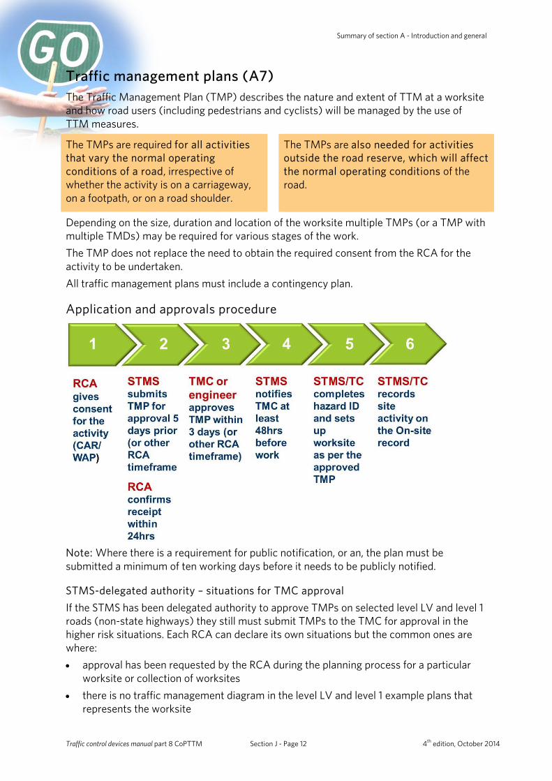
Application and approvals procedure
Note: Where there is a requirement for public notification, or an, the plan must be submitted a minimum of ten working days before it needs to be publicly notified.
STMS-delegated authority – situations for TMC approval If the STMS has been delegated authority to approve TMPs on selected level LV and level 1 roads (non-state highways) they still must submit TMPs to the TMC for approval in the higher risk situations. Each RCA can declare its own situations but the common ones are where: • approval has been requested by the RCA during the planning process for a particular
worksite or collection of worksites • there is no traffic management diagram in the level LV and level 1 example plans that
represents the worksite
Traffic control devices manual part 8 CoPTTM Section J - Page 12 4th edition, October 2014
NZ Transport Agency Summary of section A - Introduction and general
• a road needs to be closed or traffic delays for more than five minutes at any one time during the day, or for a cumulative period of 30 minutes in any one hour period, except where otherwise specified by the RCA
• a footpath will be closed and users will have to enter/cross a live lane • a cycle lane will be closed • a pedestrian crossing or traffic signal installation is affected • restricted parking, bus stops, loading zones and/or taxi stands will be affected • portable traffic signals are to be used • a lane closure is required at an intersection • signs need to be placed on a flush median • traffic moving in one direction is split around a closure • mobile operations are on roads with posted speed limit exceeding 50km/h (except for
grading operations) • the activity is an event • other situation/s as may be stipulated by the RCA.
Principles for traffic management plans (A7.3) TMPs must be consistent with CoPTTM. Traffic management measures must prioritise the treatment of the hazard(s) created by the activity in the following order: • elimination • isolation • minimisation. The person approving the TMP must be satisfied that the hazards have been managed. The TMP must be designed and drafted by an STMS. The activity and associated TTM must be carried out in such a manner as to avoid, or at least minimise, inconvenience or delay to road users whilst still providing safe conditions for both the road user and those carrying out the activity. The activity must be separated from road users wherever possible. The TTM measures proposed must not be over restrictive nor use an excessive number of signs. The TSLs must have the minimum possible reduction in speed limit for the minimum time and over a minimum length while still providing for the safety of road users and those carrying out the activity. Activities with varying on-site phases must have multiple TMPs or TMDs covering each phase. This includes unattended worksites.
Traffic control devices manual part 8 CoPTTM Section J - Page 13 4th edition, October 2014
Summary of section A - Introduction and general
Contents of traffic management plans (A7.4) The worksite-specific requirements for TMPs, blank TMP forms and a schedule of specific job requirements for traffic management and safety form are contained in section E, appendix A.
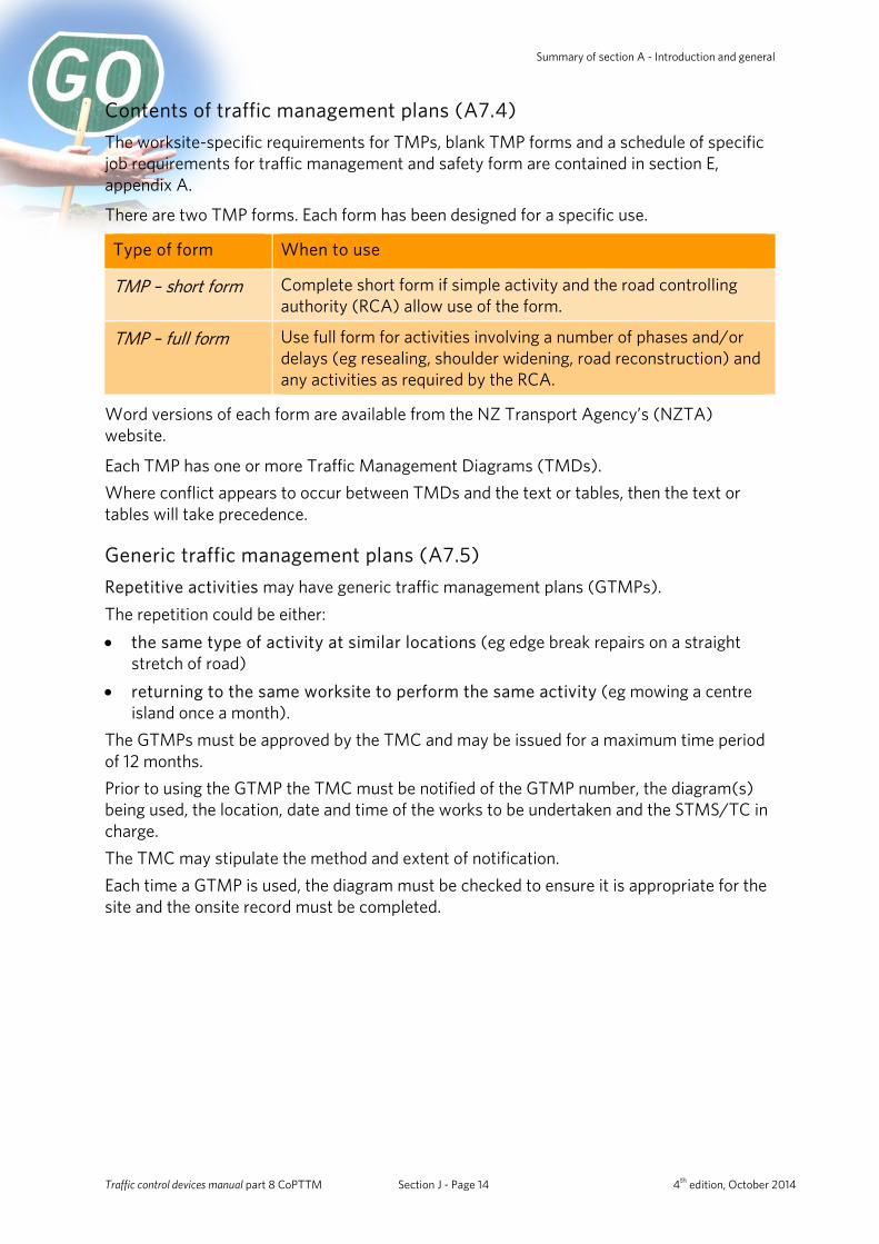
There are two TMP forms. Each form has been designed for a specific use.
Type of form When to use
TMP – short form Complete short form if simple activity and the road controlling authority (RCA) allow use of the form.
TMP – full form Use full form for activities involving a number of phases and/or delays (eg resealing, shoulder widening, road reconstruction) and any activities as required by the RCA.
Word versions of each form are available from the NZ Transport Agency’s (NZTA) website.
Each TMP has one or more Traffic Management Diagrams (TMDs). Where conflict appears to occur between TMDs and the text or tables, then the text or tables will take precedence.
Generic traffic management plans (A7.5) Repetitive activities may have generic traffic management plans (GTMPs). The repetition could be either: • the same type of activity at similar locations (eg edge break repairs on a straight
stretch of road) • returning to the same worksite to perform the same activity (eg mowing a centre
island once a month). The GTMPs must be approved by the TMC and may be issued for a maximum time period of 12 months. Prior to using the GTMP the TMC must be notified of the GTMP number, the diagram(s) being used, the location, date and time of the works to be undertaken and the STMS/TC in charge. The TMC may stipulate the method and extent of notification. Each time a GTMP is used, the diagram must be checked to ensure it is appropriate for the site and the onsite record must be completed.
Traffic control devices manual part 8 CoPTTM Section J - Page 14 4th edition, October 2014
NZ Transport Agency Summary of section A - Introduction and general
Availability of traffic management plans (A7.7)
A copy of the signed and approved TMP/generic TMPs must be available on-site at all times when the worksite is attended
For selected level LV and level 1 roads, if the TMP has been approved by the STMS under delegated authority, a copy of the TMP must be kept for one year.
Engineering exception decisions (A7.9) Any variation to CoPTTM must be in terms of a written EED which describes: What the problem is:
a. Describe the road environment constraint b. State CoPTTM requirements for the proposed activity.
Why CoPTTM-compliant TTM should not be installed. How will safety be ensured. The EED must be attached to, and form part of, the TMP for the activity. The EED must be applied across boundaries where applicable. A template for an EED is included in section E1.7 of CoPTTM.
Temporary traffic management (TTM) safety audit procedures (A8) Audits provide assurance that good TTM is being achieved. It is recommended that audits be carried out by both the RCA and any party who has activity completed for them on the roads. There are two audit forms (full audit and short audit) which can be used for the following:
Full audit Short audit
• attended and unattended static worksites • semi-static activities • mobile and inspections activities • day-time and night-time activities.
• attended and unattended static worksites • day-time and night-time activities.
People using these procedures must hold a current STMS qualification.
Traffic control devices manual part 8 CoPTTM Section J - Page 15 4th edition, October 2014

Summary of section B - Equipment
Level 1
750mm
Section B - Equipment
Signs including stands and supports (B1)
Introduction (B1.1) There are currently 2 numbering systems in use: • MOTSAM – TW-1A (old number) • TCD Rule – T1A (new number). The Level 1 TTM handbook only shows the new numbering system but both numbering systems are shown in CoPTTM. All new TMPs must use the new sign references. Existing generic traffic management plans (GTMPs) will remain current until they are due for their 12 month revision. After this date they must use the new sign references.
General (B1.2) TTM signs are set out at worksites to:
• provide advance warning • direct and protect road users, and road workers • notify road users when they are safely through a worksite. All TTM signs must comply with the NZTA’s TCD Rule and CoPTTM.
Sign standards (B1.3) All sign faces (temporary and regulatory) must have retro-reflective material backgrounds. Most temporary warning signs will have a fluorescent orange background.
Typically level 1 signs are used on level LV and level 1 roads. The minimum size for a diamond-shaped sign is 750mm x 750mm.
The minimum size for a regulatory sign is 750mm diameter. However, 600mm diameter signs may be used for mobile operations. Where insufficient lane width is a factor, the RCA may approve the use of the RD6L/R twin disc (300mm diameter).
Traffic control devices manual part 8 CoPTTM Section J - Page 16 4th edition, October 2014
NZ Transport Agency Summary of section B - Equipment
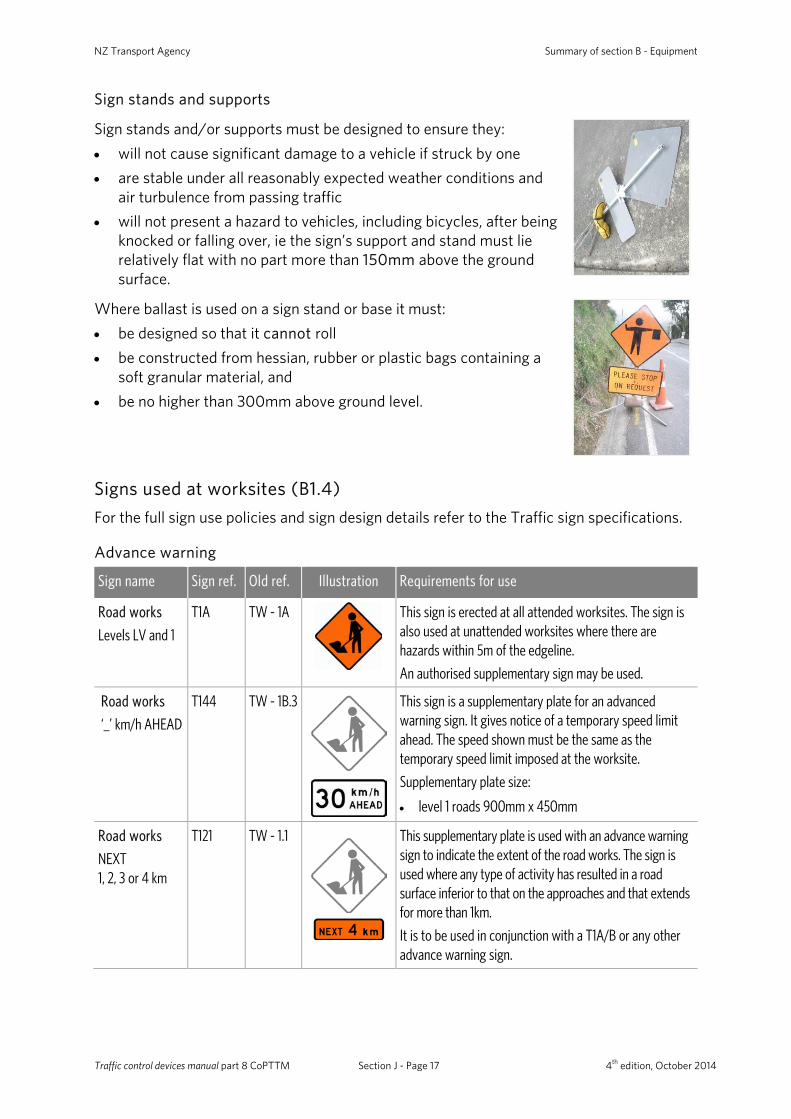
Sign stands and supports
Sign stands and/or supports must be designed to ensure they: • will not cause significant damage to a vehicle if struck by one • are stable under all reasonably expected weather conditions and
air turbulence from passing traffic • will not present a hazard to vehicles, including bicycles, after being
knocked or falling over, ie the sign’s support and stand must lie relatively flat with no part more than 150mm above the ground surface.
Where ballast is used on a sign stand or base it must: • be designed so that it cannot roll • be constructed from hessian, rubber or plastic bags containing a
soft granular material, and • be no higher than 300mm above ground level.
Signs used at worksites (B1.4) For the full sign use policies and sign design details refer to the Traffic sign specifications.
Advance warning
Sign name Sign ref. Old ref. Illustration Requirements for use
Road works
Levels LV and 1
T1A TW - 1A
This sign is erected at all attended worksites. The sign is also used at unattended worksites where there are hazards within 5m of the edgeline.
An authorised supplementary sign may be used.
Road works
‘_’ km/h AHEAD T144 TW - 1B.3
This sign is a supplementary plate for an advanced warning sign. It gives notice of a temporary speed limit ahead. The speed shown must be the same as the temporary speed limit imposed at the worksite.
Supplementary plate size:
• level 1 roads 900mm x 450mm
Road works
NEXT 1, 2, 3 or 4 km
T121 TW - 1.1
This supplementary plate is used with an advance warning sign to indicate the extent of the road works. The sign is used where any type of activity has resulted in a road surface inferior to that on the approaches and that extends for more than 1km.
It is to be used in conjunction with a T1A/B or any other advance warning sign.
Traffic control devices manual part 8 CoPTTM Section J - Page 17 4th edition, October 2014
Summary of section B - Equipment
Sign name Sign ref. Old ref. Illustration Requirements for use
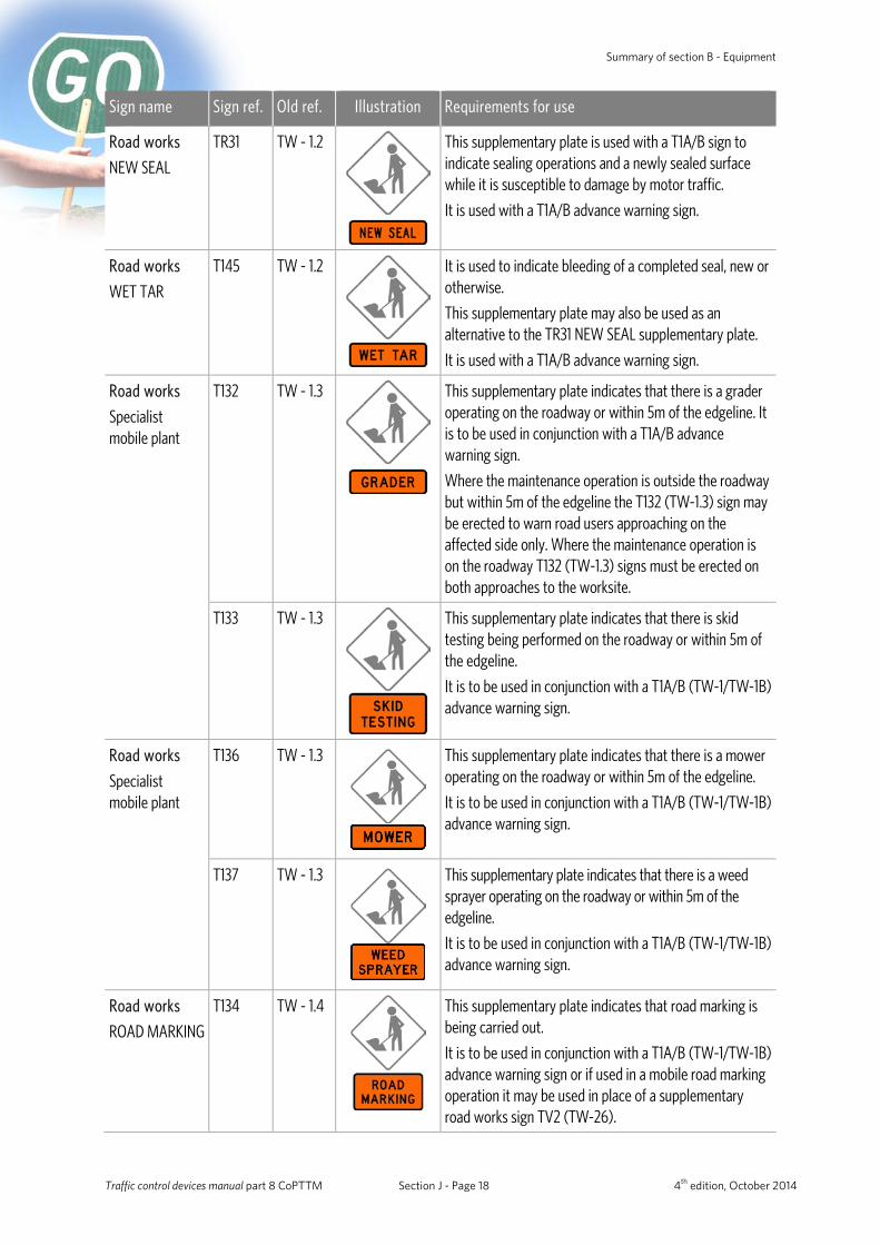
Road works
NEW SEAL
TR31 TW - 1.2
This supplementary plate is used with a T1A/B sign to indicate sealing operations and a newly sealed surface while it is susceptible to damage by motor traffic.
It is used with a T1A/B advance warning sign.
Road works
WET TAR
T145 TW - 1.2
It is used to indicate bleeding of a completed seal, new or otherwise.
This supplementary plate may also be used as an alternative to the TR31 NEW SEAL supplementary plate.
It is used with a T1A/B advance warning sign.
Road works
Specialist mobile plant
T132
TW - 1.3
This supplementary plate indicates that there is a grader operating on the roadway or within 5m of the edgeline. It is to be used in conjunction with a T1A/B advance warning sign.
Where the maintenance operation is outside the roadway but within 5m of the edgeline the T132 (TW-1.3) sign may be erected to warn road users approaching on the affected side only. Where the maintenance operation is on the roadway T132 (TW-1.3) signs must be erected on both approaches to the worksite.
T133 TW - 1.3
This supplementary plate indicates that there is skid testing being performed on the roadway or within 5m of the edgeline.
It is to be used in conjunction with a T1A/B (TW-1/TW-1B) advance warning sign.
Road works
Specialist mobile plant
T136 TW - 1.3
This supplementary plate indicates that there is a mower operating on the roadway or within 5m of the edgeline.
It is to be used in conjunction with a T1A/B (TW-1/TW-1B) advance warning sign.
T137 TW - 1.3
This supplementary plate indicates that there is a weed sprayer operating on the roadway or within 5m of the edgeline.
It is to be used in conjunction with a T1A/B (TW-1/TW-1B) advance warning sign.
Road works
ROAD MARKING
T134 TW - 1.4
This supplementary plate indicates that road marking is being carried out.
It is to be used in conjunction with a T1A/B (TW-1/TW-1B) advance warning sign or if used in a mobile road marking operation it may be used in place of a supplementary road works sign TV2 (TW-26).
Traffic control devices manual part 8 CoPTTM Section J - Page 18 4th edition, October 2014
NZ Transport Agency Summary of section B - Equipment
Sign name Sign ref. Old ref. Illustration Requirements for use
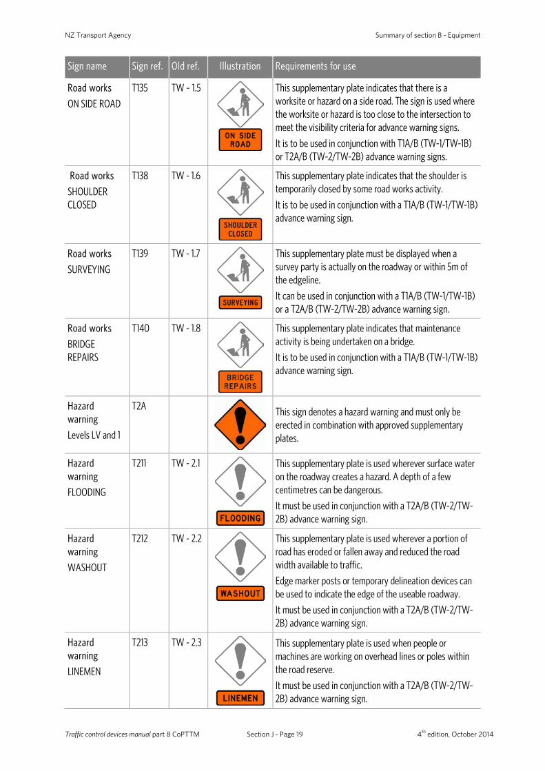
Road works
ON SIDE ROAD
T135 TW – 1.5
This supplementary plate indicates that there is a worksite or hazard on a side road. The sign is used where the worksite or hazard is too close to the intersection to meet the visibility criteria for advance warning signs.
It is to be used in conjunction with T1A/B (TW-1/TW-1B) or T2A/B (TW-2/TW-2B) advance warning signs.
Road works
SHOULDER CLOSED
T138 TW - 1.6
This supplementary plate indicates that the shoulder is temporarily closed by some road works activity.
It is to be used in conjunction with a T1A/B (TW-1/TW-1B) advance warning sign.
Road works
SURVEYING
T139 TW - 1.7
This supplementary plate must be displayed when a survey party is actually on the roadway or within 5m of the edgeline.
It can be used in conjunction with a T1A/B (TW-1/TW-1B) or a T2A/B (TW-2/TW-2B) advance warning sign.
Road works
BRIDGE REPAIRS
T140 TW - 1.8
This supplementary plate indicates that maintenance activity is being undertaken on a bridge.
It is to be used in conjunction with a T1A/B (TW-1/TW-1B) advance warning sign.
Hazard warning
Levels LV and 1
T2A
This sign denotes a hazard warning and must only be erected in combination with approved supplementary plates.
Hazard warning
FLOODING
T211 TW - 2.1
This supplementary plate is used wherever surface water on the roadway creates a hazard. A depth of a few centimetres can be dangerous.
It must be used in conjunction with a T2A/B (TW-2/TW-2B) advance warning sign.
Hazard warning
WASHOUT
T212 TW - 2.2
This supplementary plate is used wherever a portion of road has eroded or fallen away and reduced the road width available to traffic.
Edge marker posts or temporary delineation devices can be used to indicate the edge of the useable roadway.
It must be used in conjunction with a T2A/B (TW-2/TW-2B) advance warning sign.
Hazard warning
LINEMEN
T213 TW - 2.3
This supplementary plate is used when people or machines are working on overhead lines or poles within the road reserve.
It must be used in conjunction with a T2A/B (TW-2/TW-2B) advance warning sign.
Traffic control devices manual part 8 CoPTTM Section J - Page 19 4th edition, October 2014
Summary of section B - Equipment
Sign name Sign ref. Old ref. Illustration Requirements for use
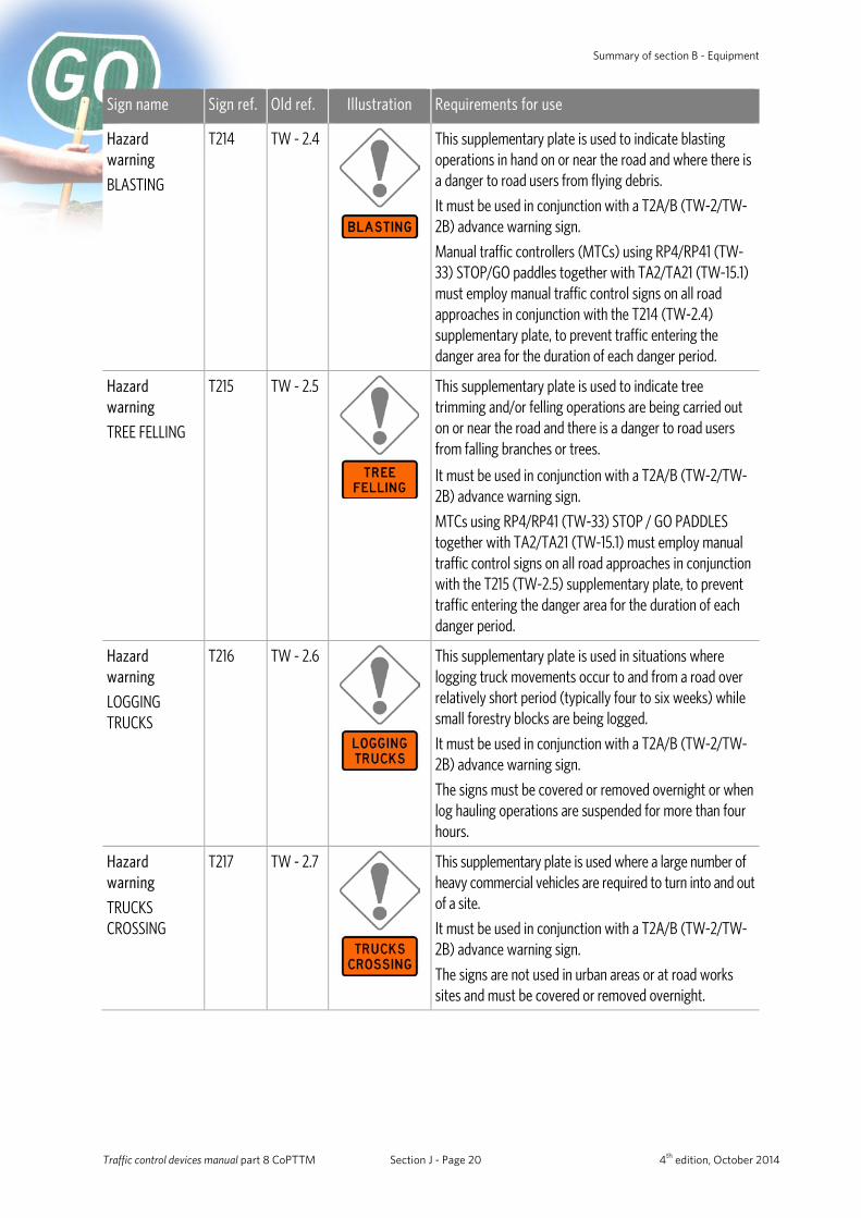
Hazard warning
BLASTING
T214 TW - 2.4
This supplementary plate is used to indicate blasting operations in hand on or near the road and where there is a danger to road users from flying debris.
It must be used in conjunction with a T2A/B (TW-2/TW-2B) advance warning sign.
Manual traffic controllers (MTCs) using RP4/RP41 (TW-33) STOP/GO paddles together with TA2/TA21 (TW-15.1) must employ manual traffic control signs on all road approaches in conjunction with the T214 (TW-2.4) supplementary plate, to prevent traffic entering the danger area for the duration of each danger period.
Hazard warning
TREE FELLING
T215 TW - 2.5
This supplementary plate is used to indicate tree trimming and/or felling operations are being carried out on or near the road and there is a danger to road users from falling branches or trees.
It must be used in conjunction with a T2A/B (TW-2/TW-2B) advance warning sign.
MTCs using RP4/RP41 (TW-33) STOP / GO PADDLES together with TA2/TA21 (TW-15.1) must employ manual traffic control signs on all road approaches in conjunction with the T215 (TW-2.5) supplementary plate, to prevent traffic entering the danger area for the duration of each danger period.
Hazard warning
LOGGING TRUCKS
T216 TW - 2.6
This supplementary plate is used in situations where logging truck movements occur to and from a road over relatively short period (typically four to six weeks) while small forestry blocks are being logged.
It must be used in conjunction with a T2A/B (TW-2/TW-2B) advance warning sign.
The signs must be covered or removed overnight or when log hauling operations are suspended for more than four hours.
Hazard warning
TRUCKS CROSSING
T217 TW - 2.7
This supplementary plate is used where a large number of heavy commercial vehicles are required to turn into and out of a site.
It must be used in conjunction with a T2A/B (TW-2/TW-2B) advance warning sign.
The signs are not used in urban areas or at road works sites and must be covered or removed overnight.
Traffic control devices manual part 8 CoPTTM Section J - Page 20 4th edition, October 2014
NZ Transport Agency Summary of section B - Equipment
Sign name Sign ref. Old ref. Illustration Requirements for use
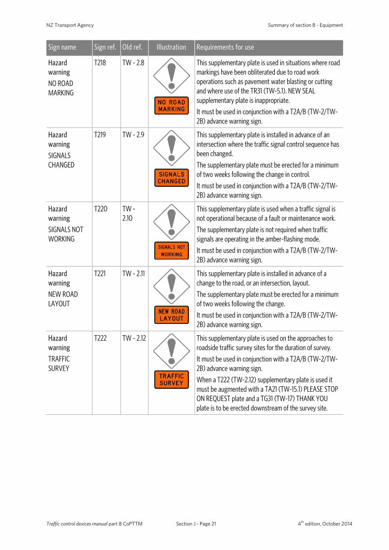
Hazard warning
NO ROAD MARKING
T218 TW - 2.8
This supplementary plate is used in situations where road markings have been obliterated due to road work operations such as pavement water blasting or cutting and where use of the TR31 (TW-5.1). NEW SEAL supplementary plate is inappropriate.
It must be used in conjunction with a T2A/B (TW-2/TW-2B) advance warning sign.
Hazard warning
SIGNALS CHANGED
T219 TW - 2.9
This supplementary plate is installed in advance of an intersection where the traffic signal control sequence has been changed.
The supplementary plate must be erected for a minimum of two weeks following the change in control.
It must be used in conjunction with a T2A/B (TW-2/TW-2B) advance warning sign.
Hazard warning
SIGNALS NOT WORKING
T220 TW - 2.10
This supplementary plate is used when a traffic signal is not operational because of a fault or maintenance work.
The supplementary plate is not required when traffic signals are operating in the amber-flashing mode.
It must be used in conjunction with a T2A/B (TW-2/TW-2B) advance warning sign.
Hazard warning
NEW ROAD LAYOUT
T221 TW - 2.11
This supplementary plate is installed in advance of a change to the road, or an intersection, layout.
The supplementary plate must be erected for a minimum of two weeks following the change.
It must be used in conjunction with a T2A/B (TW-2/TW-2B) advance warning sign.
Hazard warning
TRAFFIC SURVEY
T222 TW - 2.12
This supplementary plate is used on the approaches to roadside traffic survey sites for the duration of survey.
It must be used in conjunction with a T2A/B (TW-2/TW-2B) advance warning sign.
When a T222 (TW-2.12) supplementary plate is used it must be augmented with a TA21 (TW-15.1) PLEASE STOP ON REQUEST plate and a TG31 (TW-17) THANK YOU plate is to be erected downstream of the survey site.
Traffic control devices manual part 8 CoPTTM Section J - Page 21 4th edition, October 2014
Summary of section B - Equipment
Sign name Sign ref. Old ref. Illustration Requirements for use
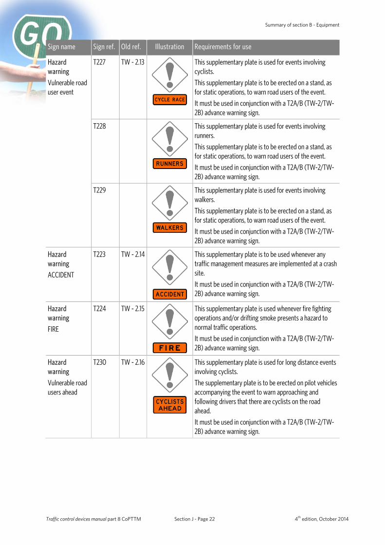
Hazard warning
Vulnerable road user event
T227 TW - 2.13
This supplementary plate is used for events involving cyclists.
This supplementary plate is to be erected on a stand, as for static operations, to warn road users of the event.
It must be used in conjunction with a T2A/B (TW-2/TW-2B) advance warning sign.
T228
This supplementary plate is used for events involving runners.
This supplementary plate is to be erected on a stand, as for static operations, to warn road users of the event.
It must be used in conjunction with a T2A/B (TW-2/TW-2B) advance warning sign.
T229
This supplementary plate is used for events involving walkers.
This supplementary plate is to be erected on a stand, as for static operations, to warn road users of the event.
It must be used in conjunction with a T2A/B (TW-2/TW-2B) advance warning sign.
Hazard warning
ACCIDENT
T223 TW - 2.14
This supplementary plate is to be used whenever any traffic management measures are implemented at a crash site.
It must be used in conjunction with a T2A/B (TW-2/TW-2B) advance warning sign.
Hazard warning
FIRE
T224 TW - 2.15
This supplementary plate is used whenever fire fighting operations and/or drifting smoke presents a hazard to normal traffic operations.
It must be used in conjunction with a T2A/B (TW-2/TW-2B) advance warning sign.
Hazard warning
Vulnerable road users ahead
T230 TW - 2.16
This supplementary plate is used for long distance events involving cyclists.
The supplementary plate is to be erected on pilot vehicles accompanying the event to warn approaching and following drivers that there are cyclists on the road ahead.
It must be used in conjunction with a T2A/B (TW-2/TW-2B) advance warning sign.
Traffic control devices manual part 8 CoPTTM Section J - Page 22 4th edition, October 2014
NZ Transport Agency Summary of section B - Equipment
Sign name Sign ref. Old ref. Illustration Requirements for use
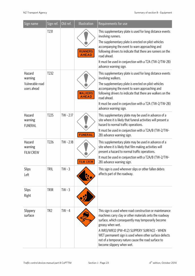
T231
This supplementary plate is used for long distance events involving runners.
The supplementary plate is erected on pilot vehicles accompanying the event to warn approaching and following drivers to indicate that there are runners on the road ahead.
It must be used in conjunction with a T2A (TW-2/TW-2B) advance warning sign.
Hazard warning
Vulnerable road users ahead
T232
This supplementary plate is used for long distance events involving walkers.
The supplementary plate is erected on pilot vehicles accompanying the event to warn approaching and following drivers to indicate that there are walkers on the road ahead.
It must be used in conjunction with a T2A (TW-2/TW-2B) advance warning sign.
Hazard warning
FUNERAL
T225 TW - 2.17
This supplementary plate may be used in advance of a site where it is likely that funeral activities will present a hazard to normal traffic operations.
It must be used in conjunction with a T2A/B (TW-2/TW-2B) advance warning sign.
Hazard warning
FILM CREW
T226 TW - 2.18
This supplementary plate may be used in advance of a site where it is likely that film making activities will present a hazard to normal traffic operations.
It must be used in conjunction with a T2A/B (TW-2/TW-2B) advance warning sign.
Slips
Left
TR1L TW - 3
This sign is used wherever slips or other fallen debris affects part of the roadway.
Slips
Right
TR1R TW - 3
Slippery surface
TR2 TW - 4
This sign is used where road construction or maintenance machines carry clay or other materials onto the roadway surface, which consequently may temporarily become greasy when wet.
A WR3/WR32 (PW-41.2) SLIPPERY SURFACE - WHEN WET permanent sign is used where other surface defects not of a temporary nature cause the road surface to become slippery when wet.
Traffic control devices manual part 8 CoPTTM Section J - Page 23 4th edition, October 2014
Summary of section B - Equipment
Sign name Sign ref. Old ref. Illustration Requirements for use
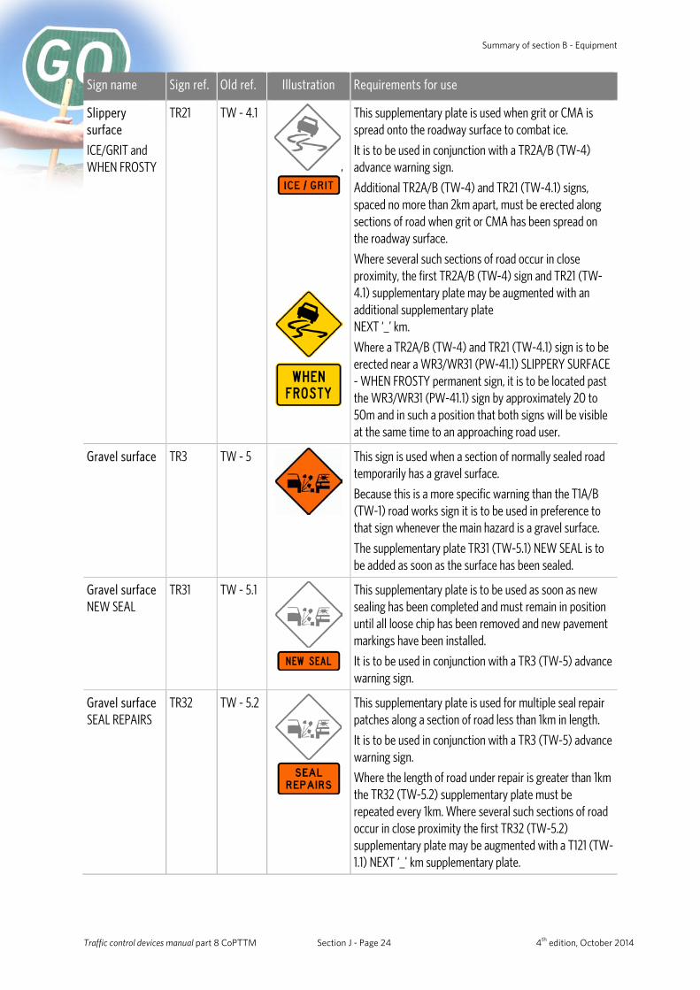
Slippery surface
ICE/GRIT and WHEN FROSTY
TR21 TW - 4.1
,
This supplementary plate is used when grit or CMA is spread onto the roadway surface to combat ice.
It is to be used in conjunction with a TR2A/B (TW-4) advance warning sign.
Additional TR2A/B (TW-4) and TR21 (TW-4.1) signs, spaced no more than 2km apart, must be erected along sections of road when grit or CMA has been spread on the roadway surface.
Where several such sections of road occur in close proximity, the first TR2A/B (TW-4) sign and TR21 (TW-4.1) supplementary plate may be augmented with an additional supplementary plate NEXT ‘_’ km.
Where a TR2A/B (TW-4) and TR21 (TW-4.1) sign is to be erected near a WR3/WR31 (PW-41.1) SLIPPERY SURFACE - WHEN FROSTY permanent sign, it is to be located past the WR3/WR31 (PW-41.1) sign by approximately 20 to 50m and in such a position that both signs will be visible at the same time to an approaching road user.
Gravel surface TR3 TW - 5
This sign is used when a section of normally sealed road temporarily has a gravel surface.
Because this is a more specific warning than the T1A/B (TW-1) road works sign it is to be used in preference to that sign whenever the main hazard is a gravel surface.
The supplementary plate TR31 (TW-5.1) NEW SEAL is to be added as soon as the surface has been sealed.
Gravel surface NEW SEAL
TR31 TW - 5.1
This supplementary plate is to be used as soon as new sealing has been completed and must remain in position until all loose chip has been removed and new pavement markings have been installed.
It is to be used in conjunction with a TR3 (TW-5) advance warning sign.
Gravel surface SEAL REPAIRS
TR32 TW - 5.2
This supplementary plate is used for multiple seal repair patches along a section of road less than 1km in length.
It is to be used in conjunction with a TR3 (TW-5) advance warning sign.
Where the length of road under repair is greater than 1km the TR32 (TW-5.2) supplementary plate must be repeated every 1km. Where several such sections of road occur in close proximity the first TR32 (TW-5.2) supplementary plate may be augmented with a T121 (TW-1.1) NEXT ‘_' km supplementary plate.
Traffic control devices manual part 8 CoPTTM Section J - Page 24 4th edition, October 2014

NZ Transport Agency Summary of section B - Equipment
Sign name Sign ref. Old ref. Illustration Requirements for use
Stock – temporary Cattle/Sheep
TF1 TW - 6
These signs are used where driven stock crosses or travels short distances along the road at infrequent intervals (greater than two days) and in such a location as to cause a traffic hazard.
The signs should only be displayed when stock is actually within the road reserve.
When the frequency of stock movements is greater (on a regular daily basis - often perhaps several times a day) or, where the lack of fences, walls, etc. along the road reserve results in continual presence of stock on the road the WF12/11 (PW-37.1/37) STOCK signs are a better option.
TF2 TW - 6.1
ROAD WORKS TV2 TW - 26
This sign indicates that this vehicle is involved with an operation on the road.
It must be used in conjunction with a vehicle-mounted flashing amber beacon.
It must be mounted on the front of the lead pilot vehicle for all mobile operations.
ROAD INSPECTION
TV3 TW - 27
This sign must be used in conjunction with vehicle-mounted flashing amber beacons and must be mounted on the rear of any vehicle conducting road inspections.
Diverge TL1 TW – 35
This sign may be used within a site where traffic lanes in the same direction are required to pass either side of a hazard.
Note: TL1 (TW-35) signs must never be used for centre lane closures.
Uneven surface TR4 TW - 36
This sign is used where road surface deformation constitutes an additional hazard at a worksite.
Traffic control devices manual part 8 CoPTTM Section J - Page 25 4th edition, October 2014
Summary of section B - Equipment
Direction and protection
Sign name Sign ref. Old ref. Illustration Requirements for use
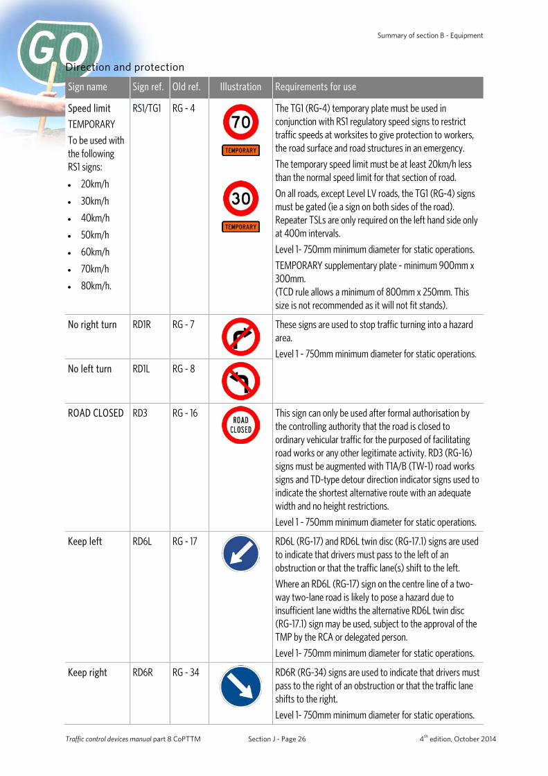
Speed limit
TEMPORARY
To be used with the following RS1 signs:
• 20km/h
• 30km/h
• 40km/h
• 50km/h
• 60km/h
• 70km/h
• 80km/h.
RS1/TG1 RG - 4
The TG1 (RG-4) temporary plate must be used in conjunction with RS1 regulatory speed signs to restrict traffic speeds at worksites to give protection to workers, the road surface and road structures in an emergency.
The temporary speed limit must be at least 20km/h less than the normal speed limit for that section of road.
On all roads, except Level LV roads, the TG1 (RG-4) signs must be gated (ie a sign on both sides of the road). Repeater TSLs are only required on the left hand side only at 400m intervals.
Level 1- 750mm minimum diameter for static operations.
TEMPORARY supplementary plate - minimum 900mm x 300mm. (TCD rule allows a minimum of 800mm x 250mm. This size is not recommended as it will not fit stands).
No right turn RD1R RG - 7
These signs are used to stop traffic turning into a hazard area.
Level 1 - 750mm minimum diameter for static operations.
No left turn RD1L RG - 8
ROAD CLOSED RD3 RG - 16
This sign can only be used after formal authorisation by the controlling authority that the road is closed to ordinary vehicular traffic for the purposed of facilitating road works or any other legitimate activity. RD3 (RG-16) signs must be augmented with T1A/B (TW-1) road works signs and TD-type detour direction indicator signs used to indicate the shortest alternative route with an adequate width and no height restrictions.
Level 1 - 750mm minimum diameter for static operations.
Keep left RD6L RG - 17
RD6L (RG-17) and RD6L twin disc (RG-17.1) signs are used to indicate that drivers must pass to the left of an obstruction or that the traffic lane(s) shift to the left.
Where an RD6L (RG-17) sign on the centre line of a two-way two-lane road is likely to pose a hazard due to insufficient lane widths the alternative RD6L twin disc (RG-17.1) sign may be used, subject to the approval of the TMP by the RCA or delegated person.
Level 1- 750mm minimum diameter for static operations.
Keep right RD6R RG - 34
RD6R (RG-34) signs are used to indicate that drivers must pass to the right of an obstruction or that the traffic lane shifts to the right.
Level 1- 750mm minimum diameter for static operations.
Traffic control devices manual part 8 CoPTTM Section J - Page 26 4th edition, October 2014
NZ Transport Agency Summary of section B - Equipment
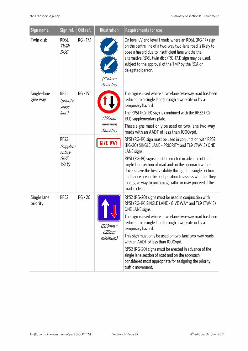
Sign name Sign ref. Old ref. Illustration Requirements for use
Twin disk RD6L TWIN DISC
RG - 17.1
(300mm diameter)
On level LV and level 1 roads where an RD6L (RG-17) sign on the centre line of a two-way two-lane road is likely to pose a hazard due to insufficient lane widths the alternative RD6L twin disc (RG-17.1) sign may be used, subject to the approval of the TMP by the RCA or delegated person.
Single-lane give way
RP51
(priority single lane)
RG - 19.1
(750mm minimum diameter)
The sign is used where a two-lane two-way road has been reduced to a single lane through a worksite or by a temporary hazard.
The RP51 (RG-19) sign is combined with the RP22 (RG-19.1) supplementary plate.
These signs must only be used on two-lane two-way roads with an AADT of less than 1000vpd.
RP51 (RG-19) sign must be used in conjunction with RP52 (RG-20) SINGLE LANE - PRIORITY and TL9 (TW-13) ONE LANE signs.
RP51 (RG-19) signs must be erected in advance of the single lane section of road and on the approach where drivers have the best visibility through the single section and hence are in the best position to assess whether they must give way to oncoming traffic or may proceed if the road is clear.
RP22
(supplementary GIVE WAY)
Single lane priority
RP52 RG - 20
(560mm x
625mm minimum)
RP52 (RG-20) signs must be used in conjunction with RP51 (RG-19) SINGLE LANE - GIVE WAY and TL9 (TW-13) ONE LANE signs.
The sign is used where a two-lane two-way road has been reduced to a single lane through a worksite or by a temporary hazard.
This sign must only be used on two-lane two-way roads with an AADT of less than 1000vpd.
RP52 (RG-20) signs must be erected in advance of the single lane section of road and on the approach considered most appropriate for assigning the priority traffic movement.
Traffic control devices manual part 8 CoPTTM Section J - Page 27 4th edition, October 2014
Summary of section B - Equipment
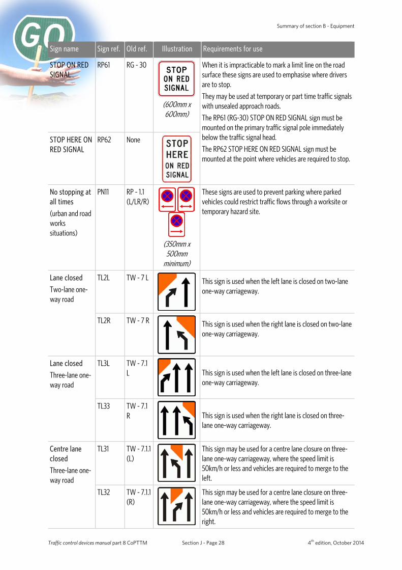
Sign name Sign ref. Old ref. Illustration Requirements for use
STOP ON RED SIGNAL
RP61 RG - 30
(600mm x 600mm)
When it is impracticable to mark a limit line on the road surface these signs are used to emphasise where drivers are to stop.
They may be used at temporary or part time traffic signals with unsealed approach roads.
The RP61 (RG-30) STOP ON RED SIGNAL sign must be mounted on the primary traffic signal pole immediately below the traffic signal head.
The RP62 STOP HERE ON RED SIGNAL sign must be mounted at the point where vehicles are required to stop.
STOP HERE ON RED SIGNAL
RP62 None
No stopping at all times
(urban and road works situations)
PN11 RP - 1.1 (L/LR/R)
(350mm x
500mm minimum)
These signs are used to prevent parking where parked vehicles could restrict traffic flows through a worksite or temporary hazard site.
Lane closed
Two-lane one-way road
TL2L TW - 7 L
This sign is used when the left lane is closed on two-lane one-way carriageway.
TL2R TW - 7 R
This sign is used when the right lane is closed on two-lane one-way carriageway.
Lane closed
Three-lane one-way road
TL3L TW - 7.1 L
This sign is used when the left lane is closed on three-lane one-way carriageway.
TL33 TW - 7.1 R
This sign is used when the right lane is closed on three-lane one-way carriageway.
Centre lane closed
Three-lane one-way road
TL31 TW - 7.1.1 (L)
This sign may be used for a centre lane closure on three-lane one-way carriageway, where the speed limit is 50km/h or less and vehicles are required to merge to the left.
TL32 TW - 7.1.1 (R)
This sign may be used for a centre lane closure on three-lane one-way carriageway, where the speed limit is 50km/h or less and vehicles are required to merge to the right.
Traffic control devices manual part 8 CoPTTM Section J - Page 28 4th edition, October 2014
NZ Transport Agency Summary of section B - Equipment
Sign name Sign ref. Old ref. Illustration Requirements for use
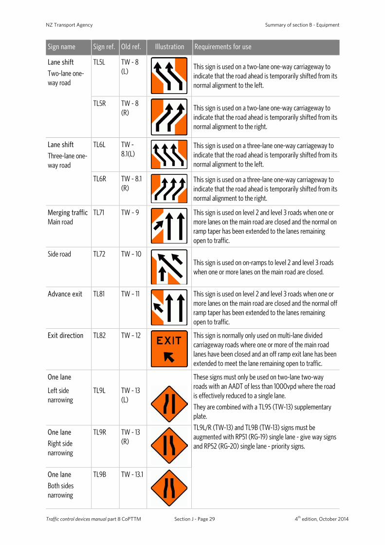
Lane shift
Two-lane one-way road
TL5L TW - 8 (L)
This sign is used on a two-lane one-way carriageway to indicate that the road ahead is temporarily shifted from its normal alignment to the left.
TL5R TW - 8 (R)
This sign is used on a two-lane one-way carriageway to indicate that the road ahead is temporarily shifted from its normal alignment to the right.
Lane shift
Three-lane one-way road
TL6L TW - 8.1(L)
This sign is used on a three-lane one-way carriageway to indicate that the road ahead is temporarily shifted from its normal alignment to the left.
TL6R TW - 8.1 (R)
This sign is used on a three-lane one-way carriageway to indicate that the road ahead is temporarily shifted from its normal alignment to the right.
Merging traffic Main road
TL71 TW – 9
This sign is used on level 2 and level 3 roads when one or more lanes on the main road are closed and the normal on ramp taper has been extended to the lanes remaining open to traffic.
Side road TL72 TW – 10
This sign is used on on-ramps to level 2 and level 3 roads when one or more lanes on the main road are closed.
Advance exit TL81 TW – 11
This sign is used on level 2 and level 3 roads when one or more lanes on the main road are closed and the normal off ramp taper has been extended to the lanes remaining open to traffic.
Exit direction TL82 TW – 12
This sign is normally only used on multi-lane divided carriageway roads where one or more of the main road lanes have been closed and an off ramp exit lane has been extended to meet the lane remaining open to traffic.
One lane These signs must only be used on two-lane two-way roads with an AADT of less than 1000vpd where the road is effectively reduced to a single lane.
They are combined with a TL9S (TW-13) supplementary plate.
TL9L/R (TW-13) and TL9B (TW-13) signs must be augmented with RP51 (RG-19) single lane - give way signs and RP52 (RG-20) single lane - priority signs.
Left side narrowing
TL9L TW - 13 (L)
One lane
Right side narrowing
TL9R TW - 13 (R)
One lane
Both sides narrowing
TL9B TW - 13.1
Traffic control devices manual part 8 CoPTTM Section J - Page 29 4th edition, October 2014
Summary of section B - Equipment
Sign name Sign ref. Old ref. Illustration Requirements for use
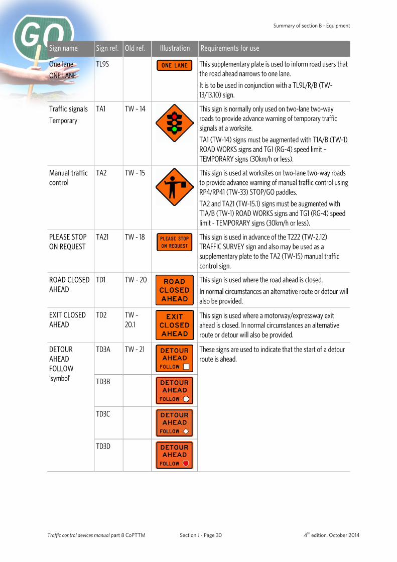
One lane
ONE LANE
TL9S This supplementary plate is used to inform road users that the road ahead narrows to one lane.
It is to be used in conjunction with a TL9L/R/B (TW-13/13.10) sign.
Traffic signals
Temporary
TA1 TW – 14
This sign is normally only used on two-lane two-way roads to provide advance warning of temporary traffic signals at a worksite.
TA1 (TW-14) signs must be augmented with T1A/B (TW-1) ROAD WORKS signs and TG1 (RG-4) speed limit – TEMPORARY signs (30km/h or less).
Manual traffic control
TA2 TW – 15
This sign is used at worksites on two-lane two-way roads to provide advance warning of manual traffic control using RP4/RP41 (TW-33) STOP/GO paddles.
TA2 and TA21 (TW-15.1) signs must be augmented with T1A/B (TW-1) ROAD WORKS signs and TG1 (RG-4) speed limit - TEMPORARY signs (30km/h or less).
PLEASE STOP ON REQUEST
TA21 TW - 18
This sign is used in advance of the T222 (TW-2.12) TRAFFIC SURVEY sign and also may be used as a supplementary plate to the TA2 (TW-15) manual traffic control sign.
ROAD CLOSED AHEAD
TD1 TW – 20
This sign is used where the road ahead is closed.
In normal circumstances an alternative route or detour will also be provided.
EXIT CLOSED AHEAD
TD2 TW – 20.1
This sign is used where a motorway/expressway exit ahead is closed. In normal circumstances an alternative route or detour will also be provided.
DETOUR AHEAD FOLLOW ‘symbol’
TD3A TW - 21
These signs are used to indicate that the start of a detour route is ahead.
TD3B
TD3C
TD3D
Traffic control devices manual part 8 CoPTTM Section J - Page 30 4th edition, October 2014
NZ Transport Agency Summary of section B - Equipment
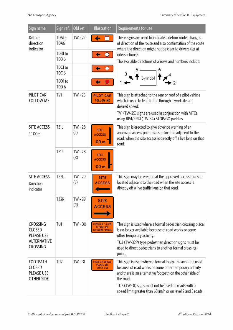
Sign name Sign ref. Old ref. Illustration Requirements for use
Detour direction indicator
TDA1 – TDA6
TW - 22
These signs are used to indicate a detour route, changes of direction of the route and also confirmation of the route where the direction might not be clear to drivers (eg at intersections).
The available directions of arrows and numbers include:
Symbol1 2
3 45 6
TDB1 to TDB 6
TDC1 to TDC 6
TDD1 to TDD 6
PILOT CAR FOLLOW ME
TV1 TW - 25
This sign is attached to the rear or roof of a pilot vehicle which is used to lead traffic through a worksite at a desired speed.
TV1 (TW-25) signs are used in conjunction with MTCs using RP4/RP41 (TW-34) STOP/GO paddles.
SITE ACCESS
‘_’ 00m
TZ1L TW - 28 (L)
This sign is erected to give advance warning of an approved access point to a site located adjacent to the road, when the site access is directly off a live lane on that road.
TZ1R
TW - 28 (R)
SITE ACCESS
Direction indicator
TZ2L TW - 29 (L)
This sign may be erected at the approved access to a site located adjacent to the road when the site access is directly off a live traffic lane on that road.
TZ2R TW - 29 (R)
CROSSING CLOSED PLEASE USE ALTERNATIVE CROSSING
TU1 TW – 30
This sign is used where a formal pedestrian crossing place is no longer available because of road works or some other temporary activity.
TU3 (TW-32P) type pedestrian direction signs must be used to direct pedestrians to another formal crossing point.
FOOTPATH CLOSED PLEASE USE OTHER SIDE
TU2 TW – 31
This sign is used where a formal footpath cannot be used because of road works or some other temporary activity and there is an alternative footpath on the other side of the road.
TU2 (TW-31) signs must not be used on roads with a speed limit greater than 65km/h or on level 2 and 3 roads.
Traffic control devices manual part 8 CoPTTM Section J - Page 31 4th edition, October 2014
Summary of section B - Equipment
Sign name Sign ref. Old ref. Illustration Requirements for use
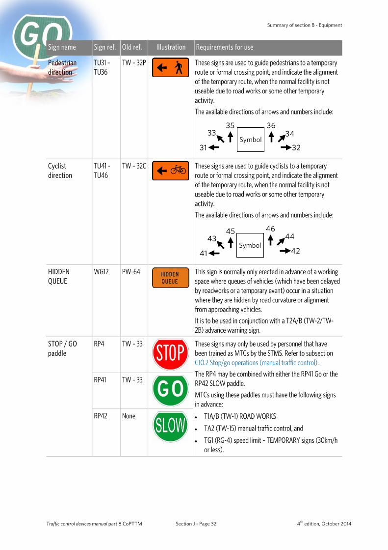
Pedestrian direction
TU31 – TU36
TW – 32P
These signs are used to guide pedestrians to a temporary route or formal crossing point, and indicate the alignment of the temporary route, when the normal facility is not useable due to road works or some other temporary activity.
The available directions of arrows and numbers include:
Symbol31 32
33 3435 36
Cyclist direction
TU41 - TU46
TW – 32C
These signs are used to guide cyclists to a temporary route or formal crossing point, and indicate the alignment of the temporary route, when the normal facility is not useable due to road works or some other temporary activity.
The available directions of arrows and numbers include:
Symbol41
4345
42
4446
HIDDEN QUEUE
WG12 PW-64
This sign is normally only erected in advance of a working space where queues of vehicles (which have been delayed by roadworks or a temporary event) occur in a situation where they are hidden by road curvature or alignment from approaching vehicles.
It is to be used in conjunction with a T2A/B (TW-2/TW-2B) advance warning sign.
STOP / GO paddle
RP4
TW – 33
These signs may only be used by personnel that have been trained as MTCs by the STMS. Refer to subsection C10.2 Stop/go operations (manual traffic control).
The RP4 may be combined with either the RP41 Go or the RP42 SLOW paddle.
MTCs using these paddles must have the following signs in advance:
• T1A/B (TW-1) ROAD WORKS
• TA2 (TW-15) manual traffic control, and
• TG1 (RG-4) speed limit – TEMPORARY signs (30km/h or less).
RP41 TW – 33
RP42 None
Traffic control devices manual part 8 CoPTTM Section J - Page 32 4th edition, October 2014
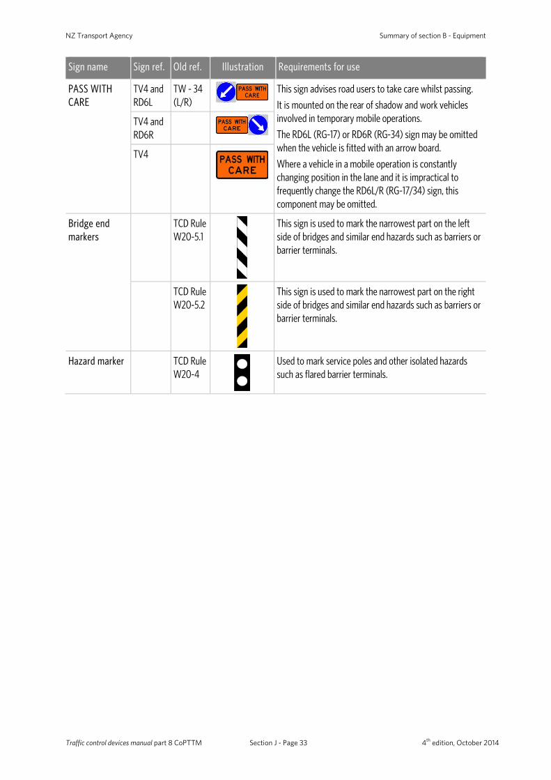
NZ Transport Agency Summary of section B - Equipment
Sign name Sign ref. Old ref. Illustration Requirements for use
PASS WITH CARE
TV4 and RD6L
TW - 34 (L/R)
This sign advises road users to take care whilst passing.
It is mounted on the rear of shadow and work vehicles involved in temporary mobile operations.
The RD6L (RG-17) or RD6R (RG-34) sign may be omitted when the vehicle is fitted with an arrow board.
Where a vehicle in a mobile operation is constantly changing position in the lane and it is impractical to frequently change the RD6L/R (RG-17/34) sign, this component may be omitted.
TV4 and RD6R
TV4
Bridge end markers
TCD Rule W20-5.1
This sign is used to mark the narrowest part on the left side of bridges and similar end hazards such as barriers or barrier terminals.
TCD Rule W20-5.2
This sign is used to mark the narrowest part on the right side of bridges and similar end hazards such as barriers or barrier terminals.
Hazard marker TCD Rule W20-4
Used to mark service poles and other isolated hazards such as flared barrier terminals.
Traffic control devices manual part 8 CoPTTM Section J - Page 33 4th edition, October 2014
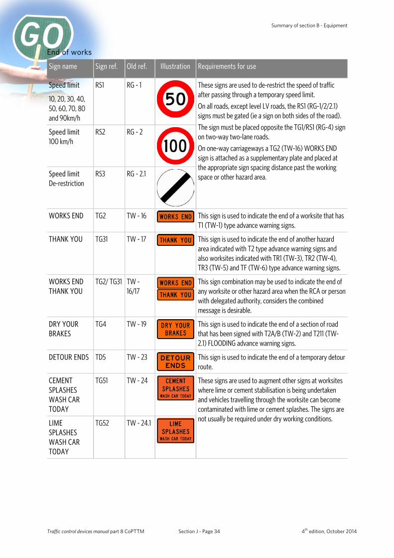
Summary of section B - Equipment
End of works
Sign name Sign ref. Old ref. Illustration Requirements for use
Speed limit RS1
RG - 1
These signs are used to de-restrict the speed of traffic after passing through a temporary speed limit.
On all roads, except level LV roads, the RS1 (RG-1/2/2.1) signs must be gated (ie a sign on both sides of the road).
The sign must be placed opposite the TG1/RS1 (RG-4) sign on two-way two-lane roads.
On one-way carriageways a TG2 (TW-16) WORKS END sign is attached as a supplementary plate and placed at the appropriate sign spacing distance past the working space or other hazard area.
10, 20, 30, 40, 50, 60, 70, 80 and 90km/h
Speed limit 100 km/h
RS2 RG - 2
Speed limit De-restriction
RS3 RG - 2.1
WORKS END TG2 TW - 16 This sign is used to indicate the end of a worksite that has T1 (TW-1) type advance warning signs.
THANK YOU TG31 TW - 17 This sign is used to indicate the end of another hazard area indicated with T2 type advance warning signs and also worksites indicated with TR1 (TW-3), TR2 (TW-4), TR3 (TW-5) and TF (TW-6) type advance warning signs.
WORKS END THANK YOU
TG2/ TG31 TW - 16/17
This sign combination may be used to indicate the end of any worksite or other hazard area when the RCA or person with delegated authority, considers the combined message is desirable.
DRY YOUR BRAKES
TG4 TW - 19
This sign is used to indicate the end of a section of road that has been signed with T2A/B (TW-2) and T211 (TW-2.1) FLOODING advance warning signs.
DETOUR ENDS TD5 TW - 23
This sign is used to indicate the end of a temporary detour route.
CEMENT SPLASHES WASH CAR TODAY
TG51 TW - 24
These signs are used to augment other signs at worksites where lime or cement stabilisation is being undertaken and vehicles travelling through the worksite can become contaminated with lime or cement splashes. The signs are not usually be required under dry working conditions. LIME
SPLASHES WASH CAR TODAY
TG52 TW - 24.1
Traffic control devices manual part 8 CoPTTM Section J - Page 34 4th edition, October 2014

NZ Transport Agency Summary of section B - Equipment
Delineation devices (B2)
General (B2.1) All delineation devices (cones, tubular delineators and barrels) must be fluorescent orange with set requirements for colour and luminance.
Manufacturers must have delineation devices tested to confirm they comply.
Compliant devices will have the letters TTMC XX/YY (month and year of compliance certificate) of a practicable size embossed or otherwise permanently marked on the upper base of the device.
The internal colour and the underside of the base must be either white or fluorescent orange to ensure the device remains visible if knocked over.
Dimensions (B2.3) All delineation devices must have a minimum height of 900mm (except for 450mm-high cones which may only be used to delineate and protect wet road markings).
Delineators must have an unballasted weight
not exceeding 7kg and have white retro-reflective bands.
Company logos Company logos applied to the sides of delineation devices must be no greater than 5000mm2 (eg 50mm x 100mm) with the top of the logo being no higher than 200mm from the road surface.
Traffic control devices manual part 8 CoPTTM Section J - Page 35 4th edition, October 2014
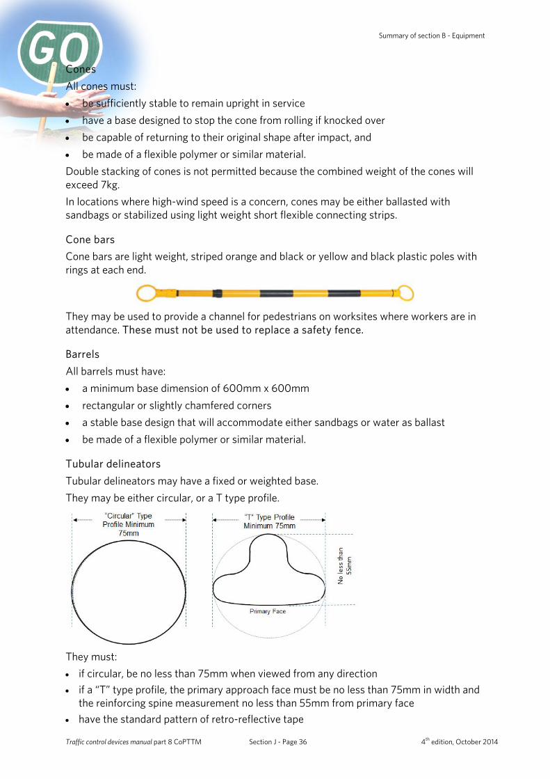
Summary of section B - Equipment
Cones All cones must: • be sufficiently stable to remain upright in service • have a base designed to stop the cone from rolling if knocked over • be capable of returning to their original shape after impact, and • be made of a flexible polymer or similar material. Double stacking of cones is not permitted because the combined weight of the cones will exceed 7kg. In locations where high-wind speed is a concern, cones may be either ballasted with sandbags or stabilized using light weight short flexible connecting strips.
Cone bars Cone bars are light weight, striped orange and black or yellow and black plastic poles with rings at each end.
They may be used to provide a channel for pedestrians on worksites where workers are in attendance. These must not be used to replace a safety fence.
Barrels All barrels must have: • a minimum base dimension of 600mm x 600mm • rectangular or slightly chamfered corners • a stable base design that will accommodate either sandbags or water as ballast • be made of a flexible polymer or similar material.
Tubular delineators Tubular delineators may have a fixed or weighted base. They may be either circular, or a T type profile.
They must: • if circular, be no less than 75mm when viewed from any direction • if a “T” type profile, the primary approach face must be no less than 75mm in width and
the reinforcing spine measurement no less than 55mm from primary face • have the standard pattern of retro-reflective tape
Traffic control devices manual part 8 CoPTTM Section J - Page 36 4th edition, October 2014
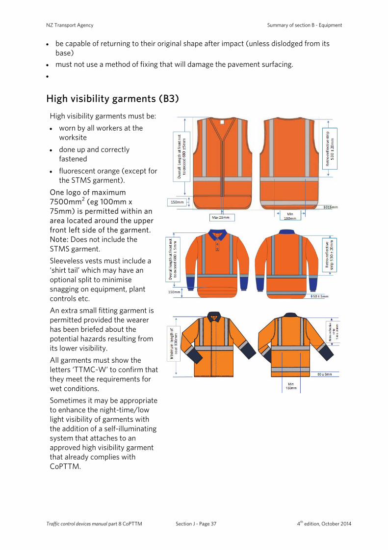
NZ Transport Agency Summary of section B - Equipment
• be capable of returning to their original shape after impact (unless dislodged from its base)
• must not use a method of fixing that will damage the pavement surfacing. •
High visibility garments (B3) High visibility garments must be: • worn by all workers at the
worksite • done up and correctly
fastened • fluorescent orange (except for
the STMS garment). One logo of maximum 7500mm2 (eg 100mm x 75mm) is permitted within an area located around the upper front left side of the garment. Note: Does not include the STMS garment. Sleeveless vests must include a ‘shirt tail’ which may have an optional split to minimise snagging on equipment, plant controls etc. An extra small fitting garment is permitted provided the wearer has been briefed about the potential hazards resulting from its lower visibility. All garments must show the letters ‘TTMC-W’ to confirm that they meet the requirements for wet conditions. Sometimes it may be appropriate to enhance the night-time/low light visibility of garments with the addition of a self-illuminating system that attaches to an approved high visibility garment that already complies with CoPTTM.
Traffic control devices manual part 8 CoPTTM Section J - Page 37 4th edition, October 2014
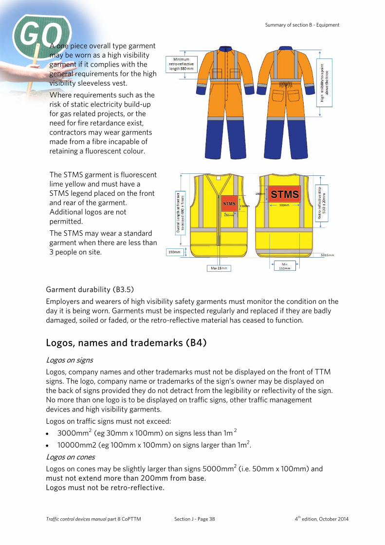
Summary of section B - Equipment
A one piece overall type garment may be worn as a high visibility garment if it complies with the general requirements for the high visibility sleeveless vest. Where requirements such as the risk of static electricity build-up for gas related projects, or the need for fire retardance exist, contractors may wear garments made from a fibre incapable of retaining a fluorescent colour.
The STMS garment is fluorescent lime yellow and must have a STMS legend placed on the front and rear of the garment. Additional logos are not permitted. The STMS may wear a standard garment when there are less than 3 people on site.
Garment durability (B3.5) Employers and wearers of high visibility safety garments must monitor the condition on the day it is being worn. Garments must be inspected regularly and replaced if they are badly damaged, soiled or faded, or the retro-reflective material has ceased to function.
Logos, names and trademarks (B4) Logos on signs Logos, company names and other trademarks must not be displayed on the front of TTM signs. The logo, company name or trademarks of the sign’s owner may be displayed on the back of signs provided they do not detract from the legibility or reflectivity of the sign. No more than one logo is to be displayed on traffic signs, other traffic management devices and high visibility garments. Logos on traffic signs must not exceed: • 3000mm2 (eg 30mm x 100mm) on signs less than 1m 2 • 10000mm2 (eg 100mm x 100mm) on signs larger than 1m2. Logos on cones Logos on cones may be slightly larger than signs 5000mm2 (i.e. 50mm x 100mm) and must not extend more than 200mm from base. Logos must not be retro-reflective.
Traffic control devices manual part 8 CoPTTM Section J - Page 38 4th edition, October 2014
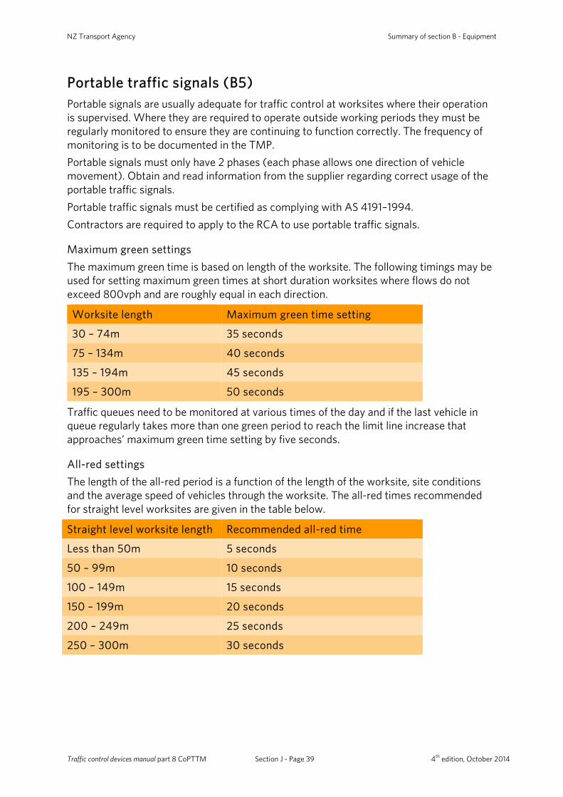
NZ Transport Agency Summary of section B - Equipment
Portable traffic signals (B5) Portable signals are usually adequate for traffic control at worksites where their operation is supervised. Where they are required to operate outside working periods they must be regularly monitored to ensure they are continuing to function correctly. The frequency of monitoring is to be documented in the TMP. Portable signals must only have 2 phases (each phase allows one direction of vehicle movement). Obtain and read information from the supplier regarding correct usage of the portable traffic signals. Portable traffic signals must be certified as complying with AS 4191–1994. Contractors are required to apply to the RCA to use portable traffic signals.
Maximum green settings The maximum green time is based on length of the worksite. The following timings may be used for setting maximum green times at short duration worksites where flows do not exceed 800vph and are roughly equal in each direction.
Worksite length Maximum green time setting
30 – 74m 35 seconds
75 – 134m 40 seconds
135 – 194m 45 seconds
195 – 300m 50 seconds
Traffic queues need to be monitored at various times of the day and if the last vehicle in queue regularly takes more than one green period to reach the limit line increase that approaches’ maximum green time setting by five seconds.
All-red settings The length of the all-red period is a function of the length of the worksite, site conditions and the average speed of vehicles through the worksite. The all-red times recommended for straight level worksites are given in the table below.
Straight level worksite length Recommended all-red time
Less than 50m 5 seconds
50 – 99m 10 seconds
100 – 149m 15 seconds
150 – 199m 20 seconds
200 – 249m 25 seconds
250 – 300m 30 seconds
Traffic control devices manual part 8 CoPTTM Section J - Page 39 4th edition, October 2014
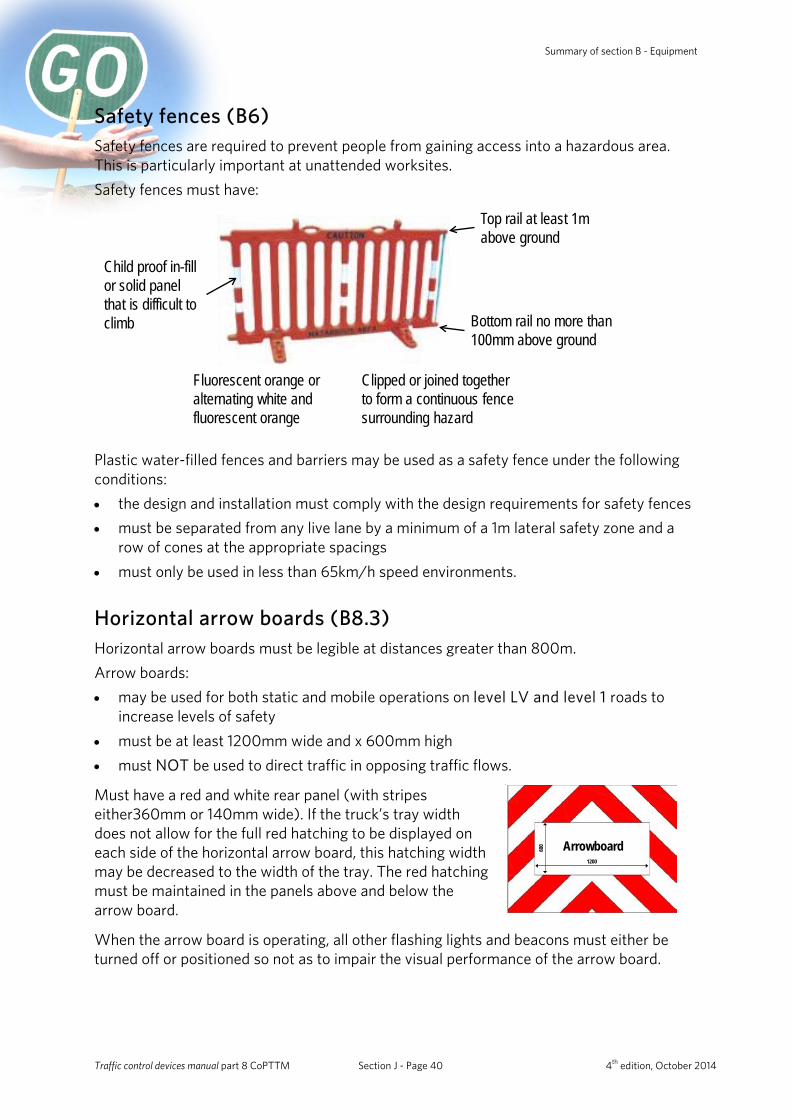
Summary of section B - Equipment
Safety fences (B6) Safety fences are required to prevent people from gaining access into a hazardous area. This is particularly important at unattended worksites. Safety fences must have:
Top rail at least 1m above ground
Bottom rail no more than 100mm above ground
Child proof in-fill or solid panel that is difficult to climb
Fluorescent orange or alternating white and fluorescent orange
Clipped or joined together to form a continuous fence surrounding hazard
Plastic water-filled fences and barriers may be used as a safety fence under the following conditions: • the design and installation must comply with the design requirements for safety fences • must be separated from any live lane by a minimum of a 1m lateral safety zone and a
row of cones at the appropriate spacings • must only be used in less than 65km/h speed environments.
Horizontal arrow boards (B8.3) Horizontal arrow boards must be legible at distances greater than 800m. Arrow boards: • may be used for both static and mobile operations on level LV and level 1 roads to
increase levels of safety • must be at least 1200mm wide and x 600mm high • must NOT be used to direct traffic in opposing traffic flows.
Must have a red and white rear panel (with stripes either360mm or 140mm wide). If the truck’s tray width does not allow for the full red hatching to be displayed on each side of the horizontal arrow board, this hatching width may be decreased to the width of the tray. The red hatching must be maintained in the panels above and below the arrow board.
Arrowboard1200
600
When the arrow board is operating, all other flashing lights and beacons must either be turned off or positioned so not as to impair the visual performance of the arrow board.
Traffic control devices manual part 8 CoPTTM Section J - Page 40 4th edition, October 2014
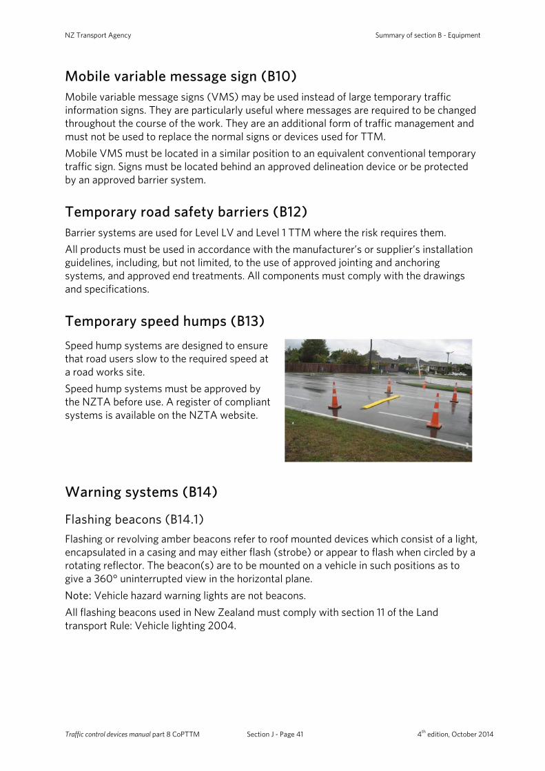
NZ Transport Agency Summary of section B - Equipment
Mobile variable message sign (B10) Mobile variable message signs (VMS) may be used instead of large temporary traffic information signs. They are particularly useful where messages are required to be changed throughout the course of the work. They are an additional form of traffic management and must not be used to replace the normal signs or devices used for TTM. Mobile VMS must be located in a similar position to an equivalent conventional temporary traffic sign. Signs must be located behind an approved delineation device or be protected by an approved barrier system.
Temporary road safety barriers (B12) Barrier systems are used for Level LV and Level 1 TTM where the risk requires them. All products must be used in accordance with the manufacturer’s or supplier’s installation guidelines, including, but not limited, to the use of approved jointing and anchoring systems, and approved end treatments. All components must comply with the drawings and specifications.
Temporary speed humps (B13) Speed hump systems are designed to ensure that road users slow to the required speed at a road works site. Speed hump systems must be approved by the NZTA before use. A register of compliant systems is available on the NZTA website.
Warning systems (B14)
Flashing beacons (B14.1) Flashing or revolving amber beacons refer to roof mounted devices which consist of a light, encapsulated in a casing and may either flash (strobe) or appear to flash when circled by a rotating reflector. The beacon(s) are to be mounted on a vehicle in such positions as to give a 360° uninterrupted view in the horizontal plane. Note: Vehicle hazard warning lights are not beacons. All flashing beacons used in New Zealand must comply with section 11 of the Land transport Rule: Vehicle lighting 2004.
Traffic control devices manual part 8 CoPTTM Section J - Page 41 4th edition, October 2014
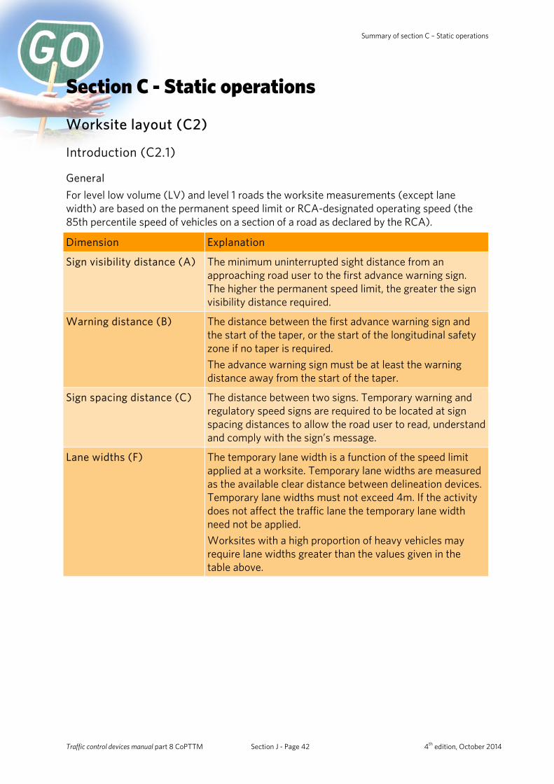
Summary of section C – Static operations
Section C - Static operations
Worksite layout (C2)
Introduction (C2.1)
General For level low volume (LV) and level 1 roads the worksite measurements (except lane width) are based on the permanent speed limit or RCA-designated operating speed (the 85th percentile speed of vehicles on a section of a road as declared by the RCA).
Dimension Explanation
Sign visibility distance (A)
The minimum uninterrupted sight distance from an approaching road user to the first advance warning sign. The higher the permanent speed limit, the greater the sign visibility distance required.
Warning distance (B)
The distance between the first advance warning sign and the start of the taper, or the start of the longitudinal safety zone if no taper is required. The advance warning sign must be at least the warning distance away from the start of the taper.
Sign spacing distance (C)
The distance between two signs. Temporary warning and regulatory speed signs are required to be located at sign spacing distances to allow the road user to read, understand and comply with the sign’s message.
Lane widths (F) The temporary lane width is a function of the speed limit applied at a worksite. Temporary lane widths are measured as the available clear distance between delineation devices. Temporary lane widths must not exceed 4m. If the activity does not affect the traffic lane the temporary lane width need not be applied. Worksites with a high proportion of heavy vehicles may require lane widths greater than the values given in the table above.
Traffic control devices manual part 8 CoPTTM Section J - Page 42 4th edition, October 2014
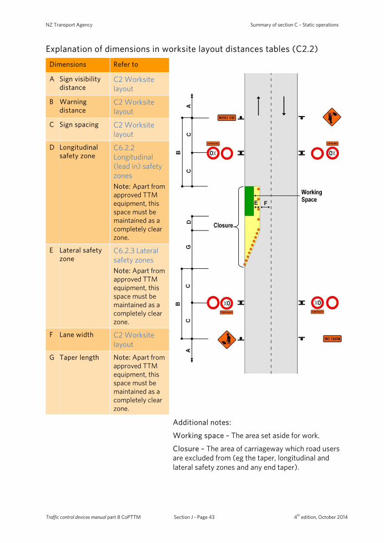
NZ Transport Agency Summary of section C – Static operations
Explanation of dimensions in worksite layout distances tables (C2.2)
Dimensions Refer to
A Sign visibility distance
C2 Worksite layout
B Warning distance
C2 Worksite layout
C Sign spacing C2 Worksite layout
D Longitudinal safety zone
C6.2.2 Longitudinal (lead in) safety zones Note: Apart from approved TTM equipment, this space must be maintained as a completely clear zone.
E Lateral safety zone
C6.2.3 Lateral safety zones Note: Apart from approved TTM equipment, this space must be maintained as a completely clear zone.
F Lane width C2 Worksite layout
G Taper length Note: Apart from approved TTM equipment, this space must be maintained as a completely clear zone.
Additional notes:
Working space – The area set aside for work.
Closure – The area of carriageway which road users are excluded from (eg the taper, longitudinal and lateral safety zones and any end taper).
Traffic control devices manual part 8 CoPTTM Section J - Page 43 4th edition, October 2014
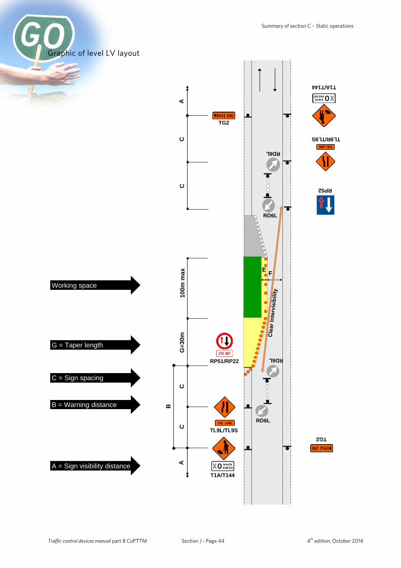
Summary of section C – Static operations
Graphic of level LV layout
F
CC
CG
=30m
TG2
C
TG2
TL9R/TL9S
RP51/RP22
TL9L/TL9S
100m
max
T1A/T144
RP52
AA
T1A/T144
RD6L
RD6L
RD6L
E
RD6L
A = Sign visibility distance
G = Taper length
B = Warning distance
Working space
B
C = Sign spacing
Traffic control devices manual part 8 CoPTTM Section J - Page 44 4th edition, October 2014

NZ Transport Agency Summary of section C – Static operations
Level LV worksite layout distances (C2.3) Permanent speed limit or RCA-designated operating speed (km/h) ≤50 60 70 80 90 100
Traffic signs A Sign visibility distance (m) 50 60 70 80 90 100 B Warning distance (m) 50 or 30* 80 105 120 135 150
C Sign spacing (m) 25 or 15* 40 50 60 70 75 Safety zones D Longitudinal (m) 0 0 0 0 0 0
E Lateral (m)+ 1 1 1 1 1 1 Tapers G Taper length (m)# 25 30 35 40 45 50
Delineation devices Cone spacing in taper (m) 2.5 2.5 5 5 5 5
Cone spacing: working space (m) 10 10 20 20 20 20
* Larger minimum distances apply on all state highways. The smaller minimum distances may be applied on other roads to accommodate road environment constraints.
+ On LV roads, the lateral safety zone may be reduced or eliminated in order to retain a single lane width. Positive traffic management and an appropriate TSL must be used.
# On non-state highways with permanent speeds 50km/h or less, a 10m taper (with cones at 1m centres) may be used when there are road environment constraints (eg intersections and commercial accesses).
On all roads where shoulder width is less than 2.5m and the activity does not affect the live lane, a 10m shoulder taper is permitted (with at least 5 cones at no greater than 2.5m centres).
A taper of 30m (with cones at 2.5m centres) must be used where manual traffic control (stop/go), portable traffic signals or priority give way are employed.
Lane widths Speed (km/h) 30 40 50 60 70 80 90 100 F Lane width (m) 2.75 2.75 3.0 3.0 3.25 3.25 3.5 3.5
Except for delineation device spacings, which are maximum values, the distances specified in the above tables are minimum values.
LV/low-risk roads
Working on roads designated as LV/low risk (less than 250 vehicles per day (vpd) - less than 20 vehicles per hour), with clear sight distance to the operation and an operating speed of less than 65km/h:
• use an appropriate advance warning sign (static installation) and amber flashing beacon on working vehicle when on the shoulder
• consider stop/go or give way control of traffic when activity encroaches onto lane.
If the above requirements cannot be achieved, the operation must be modified to comply with the requirements of a higher risk rating.
Traffic control devices manual part 8 CoPTTM Section J - Page 45 4th edition, October 2014

Summary of section C – Static operations
Graphic of level 1 layout
CC
CC
DG
RD6L
F F
BB
TG2TG2
T1A/T144T1A/T144
RS1/RS2/ RS3
RS1/RS2/ RS3
RS1/RS2/ RS3
RS1/RS2/ RS3
RS1/TG1RS1/TG1
RS1/TG1RS1/TG1
AA
E
G
RD6L
A = Sign visibility distance
C = Sign spacing
G = Taper length
D = Longitudinal safty zone
B = Warning distance
Working space
Traffic control devices manual part 8 CoPTTM Section J - Page 46 4th edition, October 2014
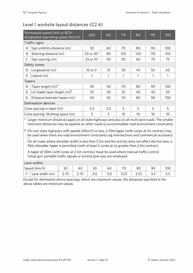
NZ Transport Agency Summary of section C – Static operations
Level 1 worksite layout distances (C2.4)
Permanent speed limit or RCA-designated operating speed (km/h) ≤50 60 70 80 90 100
Traffic signs A Sign visibility distance (m) 50 60 70 80 90 100 B Warning distance (m) 50 or 30* 80 105 120 135 150 C Sign spacing (m) 25 or 15* 40 50 60 70 75
Safety zones D Longitudinal (m) 10 or 5* 15 30 45 55 60 E Lateral (m) 1 1 1 1 1 1
Tapers G Taper length (m)# 30 50 70 80 90 100 G LV roads taper length (m)# 25 30 35 40 45 50 K Distance between tapers (m) 40 50 70 80 90 100
Delineation devices Cone spacing in taper (m) 2.5 2.5 5 5 5 5 Cone spacing: Working space (m) 5 5 10 10 10 10 * Larger minimum distances apply on all state highways and also on all multi-lane roads. The smaller
minimum distances may be applied on other roads to accommodate road environment constraints.
# On non-state highways with speeds 50km/h or less, a 10m taper (with cones at 1m centres) may be used when there are road environment constraints (eg intersections and commercial accesses).
On all roads where shoulder width is less than 2.5m and the activity does not affect the live lane, a 10m shoulder taper is permitted (with at least 5 cones at no greater than 2.5m centres).
A taper of 30m (with cones at 2.5m centres) must be used where manual traffic control (stop/go), portable traffic signals or priority give way are employed.
Lane widths Speed (km/h) 30 40 50 60 70 80 90 100 F Lane width (m) 2.75 2.75 3.0 3.0 3.25 3.25 3.5 3.5
Except for delineation device spacings, which are maximum values, the distances specified in the above tables are minimum values.
Traffic control devices manual part 8 CoPTTM Section J - Page 47 4th edition, October 2014
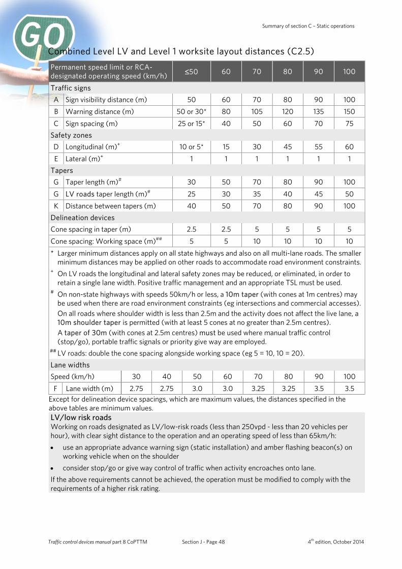
Summary of section C – Static operations
Combined Level LV and Level 1 worksite layout distances (C2.5) Permanent speed limit or RCA-designated operating speed (km/h) ≤50 60 70 80 90 100
Traffic signs A Sign visibility distance (m) 50 60 70 80 90 100 B Warning distance (m) 50 or 30* 80 105 120 135 150
C Sign spacing (m) 25 or 15* 40 50 60 70 75 Safety zones D Longitudinal (m)+ 10 or 5* 15 30 45 55 60
E Lateral (m)+ 1 1 1 1 1 1 Tapers G Taper length (m)# 30 50 70 80 90 100
G LV roads taper length (m)# 25 30 35 40 45 50 K Distance between tapers (m) 40 50 70 80 90 100
Delineation devices Cone spacing in taper (m) 2.5 2.5 5 5 5 5
Cone spacing: Working space (m)## 5 5 10 10 10 10 * Larger minimum distances apply on all state highways and also on all multi-lane roads. The smaller
minimum distances may be applied on other roads to accommodate road environment constraints. + On LV roads the longitudinal and lateral safety zones may be reduced, or eliminated, in order to
retain a single lane width. Positive traffic management and an appropriate TSL must be used. # On non-state highways with speeds 50km/h or less, a 10m taper (with cones at 1m centres) may
be used when there are road environment constraints (eg intersections and commercial accesses). On all roads where shoulder width is less than 2.5m and the activity does not affect the live lane, a 10m shoulder taper is permitted (with at least 5 cones at no greater than 2.5m centres). A taper of 30m (with cones at 2.5m centres) must be used where manual traffic control (stop/go), portable traffic signals or priority give way are employed.
## LV roads: double the cone spacing alongside working space (eg 5 = 10, 10 = 20). Lane widths Speed (km/h) 30 40 50 60 70 80 90 100
F Lane width (m) 2.75 2.75 3.0 3.0 3.25 3.25 3.5 3.5 Except for delineation device spacings, which are maximum values, the distances specified in the above tables are minimum values. LV/low risk roads Working on roads designated as LV/low-risk roads (less than 250vpd - less than 20 vehicles per hour), with clear sight distance to the operation and an operating speed of less than 65km/h: • use an appropriate advance warning sign (static installation) and amber flashing beacon(s) on
working vehicle when on the shoulder • consider stop/go or give way control of traffic when activity encroaches onto lane. If the above requirements cannot be achieved, the operation must be modified to comply with the requirements of a higher risk rating.
Traffic control devices manual part 8 CoPTTM Section J - Page 48 4th edition, October 2014

NZ Transport Agency Summary of section C – Static operations
Signs and worksite zones (C3)
Three worksite zones
TTM signs provide the road user with information on:
Zone Explanation
Advance warning
The presence of the worksite and the type of hazard.
Direction and protection
The route they are required to travel to negotiate the worksite safely. The areas of the road which may and may not be used. The start and end of the TSL for the worksite.
End of works The end of the hazard created by the worksite and the return of normal road operating conditions.
Traffic control devices manual part 8 CoPTTM Section J - Page 49 4th edition, October 2014
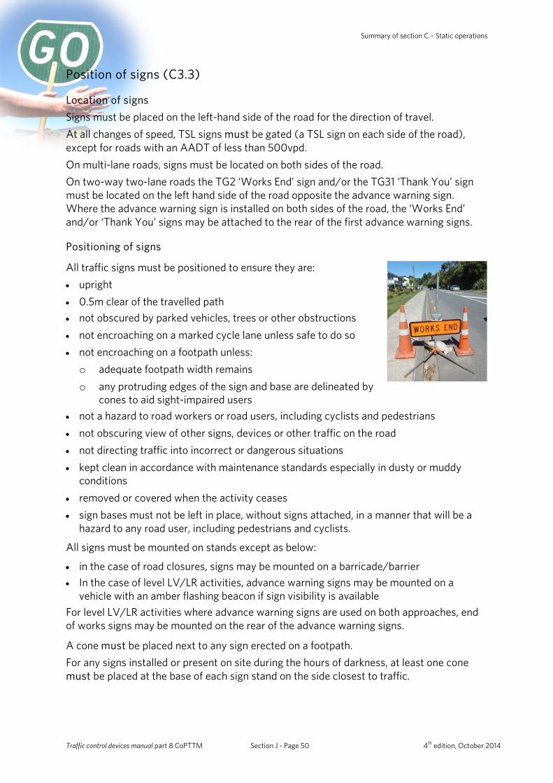
Summary of section C – Static operations
Position of signs (C3.3)
Location of signs Signs must be placed on the left-hand side of the road for the direction of travel. At all changes of speed, TSL signs must be gated (a TSL sign on each side of the road), except for roads with an AADT of less than 500vpd. On multi-lane roads, signs must be located on both sides of the road. On two-way two-lane roads the TG2 ‘Works End’ sign and/or the TG31 ‘Thank You’ sign must be located on the left hand side of the road opposite the advance warning sign. Where the advance warning sign is installed on both sides of the road, the ‘Works End’ and/or ‘Thank You’ signs may be attached to the rear of the first advance warning signs.
Positioning of signs
All traffic signs must be positioned to ensure they are: • upright • 0.5m clear of the travelled path • not obscured by parked vehicles, trees or other obstructions • not encroaching on a marked cycle lane unless safe to do so • not encroaching on a footpath unless: o adequate footpath width remains o any protruding edges of the sign and base are delineated by
cones to aid sight-impaired users
• not a hazard to road workers or road users, including cyclists and pedestrians • not obscuring view of other signs, devices or other traffic on the road • not directing traffic into incorrect or dangerous situations • kept clean in accordance with maintenance standards especially in dusty or muddy
conditions • removed or covered when the activity ceases • sign bases must not be left in place, without signs attached, in a manner that will be a
hazard to any road user, including pedestrians and cyclists.
All signs must be mounted on stands except as below:
• in the case of road closures, signs may be mounted on a barricade/barrier • In the case of level LV/LR activities, advance warning signs may be mounted on a
vehicle with an amber flashing beacon if sign visibility is available For level LV/LR activities where advance warning signs are used on both approaches, end of works signs may be mounted on the rear of the advance warning signs.
A cone must be placed next to any sign erected on a footpath. For any signs installed or present on site during the hours of darkness, at least one cone must be placed at the base of each sign stand on the side closest to traffic.
Traffic control devices manual part 8 CoPTTM Section J - Page 50 4th edition, October 2014
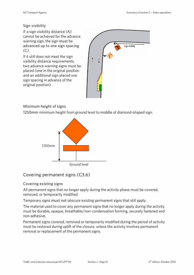
NZ Transport Agency Summary of section C – Static operations
Ground level
1250mm
Sign visibility If a sign visibility distance (A) cannot be achieved for the advance warning sign, the sign must be advanced up to one sign spacing (C). If it still does not meet the sign visibility distance requirements, two advance warning signs must be placed (one in the original position and an additional sign placed one sign spacing in advance of the original position).
Sign visibility
Minimum height of signs 1250mm minimum height from ground level to middle of diamond-shaped sign.
Covering permanent signs (C3.6)
Covering existing signs All permanent signs that no longer apply during the activity phase must be covered, removed, or temporarily modified. Temporary signs must not obscure existing permanent signs that still apply. The material used to cover any permanent signs that no longer apply during the activity must be durable, opaque, breathable/non-condensation forming, securely fastened and non-adhesive. Permanent signs covered, removed or temporarily modified during the period of activity must be restored during uplift of the closure, unless the activity involves permanent removal or replacement of the permanent signs.
Traffic control devices manual part 8 CoPTTM Section J - Page 51 4th edition, October 2014
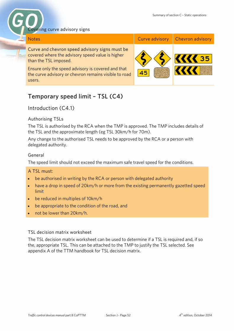
Summary of section C – Static operations
Covering curve advisory signs
Notes Curve advisory Chevron advisory
Curve and chevron speed advisory signs must be covered where the advisory speed value is higher than the TSL imposed.
Ensure only the speed advisory is covered and that the curve advisory or chevron remains visible to road users.
Temporary speed limit – TSL (C4)
Introduction (C4.1)
Authorising TSLs The TSL is authorised by the RCA when the TMP is approved. The TMP includes details of the TSL and the approximate length (eg TSL 30km/h for 70m). Any change to the authorised TSL needs to be approved by the RCA or a person with delegated authority.
General The speed limit should not exceed the maximum safe travel speed for the conditions.
A TSL must: • be authorised in writing by the RCA or person with delegated authority • have a drop in speed of 20km/h or more from the existing permanently gazetted speed
limit • be reduced in multiples of 10km/h • be appropriate to the condition of the road, and • not be lower than 20km/h.
TSL decision matrix worksheet The TSL decision matrix worksheet can be used to determine if a TSL is required and, if so the, appropriate TSL. This can be attached to the TMP to justify the TSL selected. See appendix A of the TTM handbook for TSL decision matrix.
Traffic control devices manual part 8 CoPTTM Section J - Page 52 4th edition, October 2014
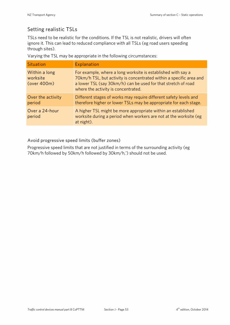
NZ Transport Agency Summary of section C – Static operations
Setting realistic TSLs TSLs need to be realistic for the conditions. If the TSL is not realistic, drivers will often ignore it. This can lead to reduced compliance with all TSLs (eg road users speeding through sites). Varying the TSL may be appropriate in the following circumstances:
Situation Explanation
Within a long worksite (over 400m)
For example, where a long worksite is established with say a 70km/h TSL, but activity is concentrated within a specific area and a lower TSL (say 30km/h) can be used for that stretch of road where the activity is concentrated.
Over the activity period
Different stages of works may require different safety levels and therefore higher or lower TSLs may be appropriate for each stage.
Over a 24-hour period
A higher TSL might be more appropriate within an established worksite during a period when workers are not at the worksite (eg at night).
Avoid progressive speed limits (buffer zones) Progressive speed limits that are not justified in terms of the surrounding activity (eg 70km/h followed by 50km/h followed by 30km/h,’) should not be used.
Traffic control devices manual part 8 CoPTTM Section J - Page 53 4th edition, October 2014

Summary of section C – Static operations
Location of TSLs (C4.3)
Sign location: • At every change in
speed the speed signs must be gated across the road (signs placed on both sides of the road facing towards oncoming traffic).
• Gated speed signs are not required on roads with an AADT of less than 500 vehicles.
• Gated TSL signs must not be offset by more than 20m along the road.
• Where the TSL begins, place the relevant RS1and TG1 signs.
• The relevant permanent speed sign RS1, RS2 or RS3 must be placed at the end of every temporary speed limit.
TG2
TG2
T1A/T144
RS1/RS2/ RS3
RS1/RS2/ RS3
RS1/RS2/ RS3
RS1/RS2/ RS3
RS1/TG1
RS1/TG1
RS1/TG1
RS1/TG1
T1A/T144
FE
RD6L
RD6L
On level 1 roads with a permanent speed limit of 100km/h, cones are required from the TSL to the taper if the speed is reduced by more than 30km/h.
Any side road entering an area subject to a TSL must also have a TSL and the relevant permanent speed limit installed to derestrict the TSL. Signs for the return to the relevant permanent speed limit - RS1, RS2 or RS3: • On two-way two-lane roads must be placed on each side of the road at the same
point as the TSL for the opposite direction. • On one-way roads may be placed with the Works End sign as a supplementary plate.
The signs are to be placed one sign spacing from the hazard.
Traffic control devices manual part 8 CoPTTM Section J - Page 54 4th edition, October 2014
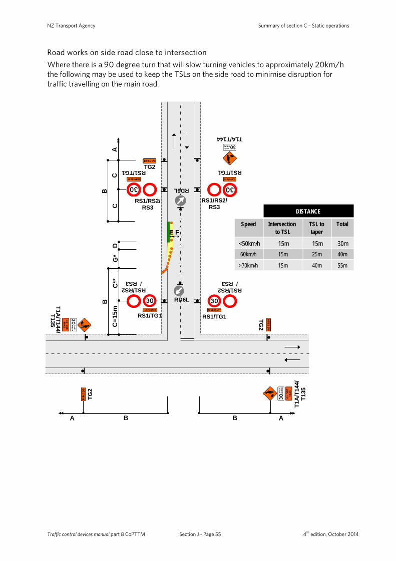
NZ Transport Agency Summary of section C – Static operations
C
TG2
TG2
RS1/RS2/ RS3
RS1/RS2/ RS3
RS1/TG1
DG
*C
**
T1A/T144
T1A
/T14
4/T1
35
RS1/TG1
C=1
5m
RS1/RS2/ RS3
RS1/TG1
C
RS1/RS2/ RS3
RS1/TG1
A
E F
B
AB
B
A B
TG2
RD6L
RD6L
T1A/T144/
T135
Road works on side road close to intersection Where there is a 90 degree turn that will slow turning vehicles to approximately 20km/h the following may be used to keep the TSLs on the side road to minimise disruption for traffic travelling on the main road.
DISTANCE
Speed Intersection to TSL
TSL to taper
Total
<50km/h 15m 15m 30m60km/h 15m 25m 40m
>70km/h 15m 40m 55m
Traffic control devices manual part 8 CoPTTM Section J - Page 55 4th edition, October 2014
Summary of section C – Static operations
General requirements for TSLs (C4.4)
Repeater signs On long worksites TSL signs must be repeated on the left-hand side of road at 400m maximum intervals (on multi-lane roads repeater signs must be gated).
Duration TSLs must be removed as soon as the circumstances under which the speed restriction was imposed no longer exist.
Covering existing speed limits When placing a TSL, any existing speed signs within the TSL area that show a speed other than the TSL must be covered (except for an overhead gantry).
Recording details of the placement of TSL The placement of the TSL signs sets the speed limit. To be legally enforceable the location and time of placement of the TSL must be recorded. Details for the location and placement of the TSL must be recorded in either the on-site record, or company documentation (if it contains the same TSL information as the on-site record). The details that must be recorded are: • date and time TSL installed • placement (route positions, house numbers or relative to a fixed point such as culvert or
bridge marker) • length of road (m) affected by the TSL • date and time TSL removed. The accuracy of details is to be within ±20m. The details of the placement of the TSL must be retained for at least 12 months, or longer if the worksite is under investigation.
Excessive or inappropriate use of TSLs If during an audit of a worksite it is determined that there is excessive or inappropriate use of TSLs (eg leaving in place a 30km/h TSL once works have been removed or finished) a non-conformance will be issued, regardless of the overall worksite condition rating.
Delineation devices (C5)
Introduction (C5.1)
General Permanent road markings should not be altered for short-term worksites. Different types of devices should not be mixed or used over distances of less than 100m. Devices in critical areas of the layout (eg cone taper) must be in acceptable condition at all times.
Traffic control devices manual part 8 CoPTTM Section J - Page 56 4th edition, October 2014

NZ Transport Agency Summary of section C – Static operations
Placement Delineation devices must be placed in accordance with the appropriate layout distance tables. These devices must be installed in straight lines and/or smooth curves to help road users travel past the hazard.
All cone spacings are measured from cone centre to centre, except for lane width where it is measured from cone edge to edge.
Edge delineation If edge marker posts are removed, temporary delineation must be installed. Where a hazard is created, side delineation must be used to guide the road user past the hazard.
Safety zones (C6)
Introduction (C6.1)
General
The safety zones (including coned tapers) must be clear zones. This means no arrow boards, equipment storage, stockpiling, working or walking in the safety zones. Signs and delineation devices are the only pieces of equipment allowed in the safety zones.
An adequate working space must be provided within the closure to allow for the movement of workers, equipment, materials and vehicles, including sufficient waiting and storage space for the above items.
E
D Longitudinal Safety Zone
G Taper
Lateral Safety Zone
Traffic control devices manual part 8 CoPTTM Section J - Page 57 4th edition, October 2014
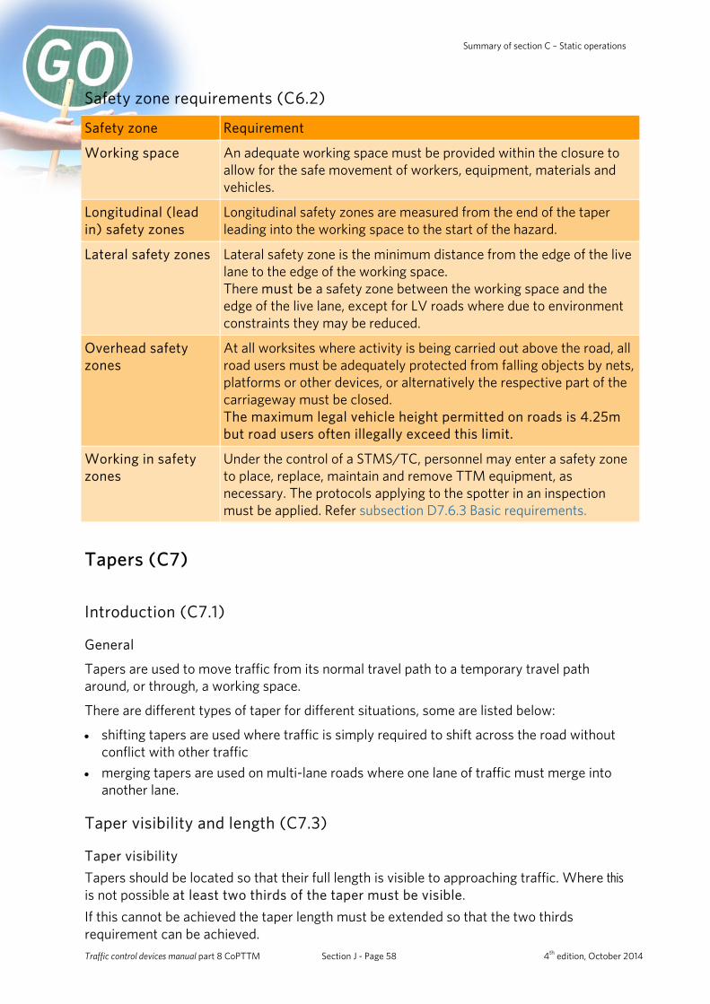
Summary of section C – Static operations
Safety zone requirements (C6.2)
Safety zone Requirement
Working space An adequate working space must be provided within the closure to allow for the safe movement of workers, equipment, materials and vehicles.
Longitudinal (lead in) safety zones
Longitudinal safety zones are measured from the end of the taper leading into the working space to the start of the hazard.
Lateral safety zones Lateral safety zone is the minimum distance from the edge of the live lane to the edge of the working space. There must be a safety zone between the working space and the edge of the live lane, except for LV roads where due to environment constraints they may be reduced.
Overhead safety zones
At all worksites where activity is being carried out above the road, all road users must be adequately protected from falling objects by nets, platforms or other devices, or alternatively the respective part of the carriageway must be closed. The maximum legal vehicle height permitted on roads is 4.25m but road users often illegally exceed this limit.
Working in safety zones
Under the control of a STMS/TC, personnel may enter a safety zone to place, replace, maintain and remove TTM equipment, as necessary. The protocols applying to the spotter in an inspection must be applied. Refer subsection D7.6.3 Basic requirements.
Tapers (C7)
Introduction (C7.1)
General
Tapers are used to move traffic from its normal travel path to a temporary travel path around, or through, a working space.
There are different types of taper for different situations, some are listed below:
• shifting tapers are used where traffic is simply required to shift across the road without conflict with other traffic
• merging tapers are used on multi-lane roads where one lane of traffic must merge into another lane.
Taper visibility and length (C7.3)
Taper visibility Tapers should be located so that their full length is visible to approaching traffic. Where this is not possible at least two thirds of the taper must be visible. If this cannot be achieved the taper length must be extended so that the two thirds requirement can be achieved. Traffic control devices manual part 8 CoPTTM Section J - Page 58 4th edition, October 2014
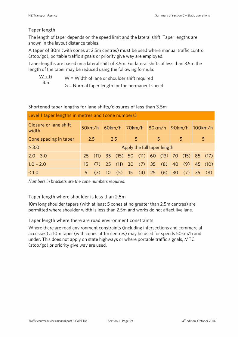
NZ Transport Agency Summary of section C – Static operations
Taper length The length of taper depends on the speed limit and the lateral shift. Taper lengths are shown in the layout distance tables. A taper of 30m (with cones at 2.5m centres) must be used where manual traffic control (stop/go), portable traffic signals or priority give way are employed. Taper lengths are based on a lateral shift of 3.5m. For lateral shifts of less than 3.5m the length of the taper may be reduced using the following formula:
W x G 3.5
W = Width of lane or shoulder shift required G = Normal taper length for the permanent speed
Shortened taper lengths for lane shifts/closures of less than 3.5m
Level 1 taper lengths in metres and (cone numbers)
Closure or lane shift width 50km/h 60km/h 70km/h 80km/h 90km/h 100km/h
Cone spacing in taper 2.5 2.5 5 5 5 5
> 3.0 Apply the full taper length
2.0 – 3.0 25 (11) 35 (15) 50 (11) 60 (13) 70 (15) 85 (17)
1.0 – 2.0 15 (7) 25 (11) 30 (7) 35 (8) 40 (9) 45 (10)
< 1.0 5 (3) 10 (5) 15 (4) 25 (6) 30 (7) 35 (8)
Numbers in brackets are the cone numbers required.
Taper length where shoulder is less than 2.5m 10m long shoulder tapers (with at least 5 cones at no greater than 2.5m centres) are permitted where shoulder width is less than 2.5m and works do not affect live lane.
Taper length where there are road environment constraints Where there are road environment constraints (including intersections and commercial accesses) a 10m taper (with cones at 1m centres) may be used for speeds 50km/h and under. This does not apply on state highways or where portable traffic signals, MTC (stop/go) or priority give way are used.
Traffic control devices manual part 8 CoPTTM Section J - Page 59 4th edition, October 2014

Summary of section C – Static operations
Shoulder and lane closures (C8)
Shoulders and roadside areas (C8.1)
Location on road Type of closure
Explanation
Shoulder closure
Shoulder closures are used to provide minimal disruption to traffic. If the activity is on a sealed or unsealed shoulder, the shoulder should be closed with a T138 ‘SHOULDER CLOSED’ supplementary plate attached to the T1A ‘ROAD WORKS’ sign.
Roadside activities with speed limits of less than 65km/h:
• Activity on the berm or footpath does not require advance warning
• TTM must be provided where pedestrians or cyclists are affected
• Advance warning and end of works signs are optional if: o the work vehicle (light truck or smaller) is
parked in a legal parallel car park, and o vehicle is only accessed from the off
traffic side • Large plant and machinery must not be used
in this situation. If it is used a more substantial closure is required.
Berm
Parki
ng La
ne
Traff
ic La
ne
Footp
ath
Wor
k ve
hicl
e
Where work is carried out in the legal parking lane, the following minimum standard of TTM must be provided: • a 10m taper in front of the work vehicle with a
longitudinal safety zone • cones alongside the work vehicle and the
working space with a 1m lateral safety zone • at least one amber flashing beacon on work
vehicle • a T1A (or other appropriate advance warning
sign) mounted on the back of the work vehicle • the work vehicle is no larger than a light truck.
Large plant and machinery must not be used in this situation; a more substantial closure is required.
Berm
Parki
ng La
ne
Traff
ic La
ne
Footp
athW
ork
vehi
cle
D
E
G=10
m
T1A
Traffic control devices manual part 8 CoPTTM Section J - Page 60 4th edition, October 2014
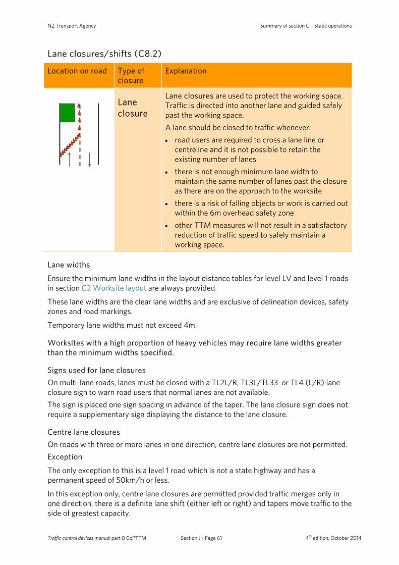
NZ Transport Agency Summary of section C – Static operations
Lane closures/shifts (C8.2)
Location on road Type of closure
Explanation
Lane closure
Lane closures are used to protect the working space. Traffic is directed into another lane and guided safely past the working space. A lane should be closed to traffic whenever: • road users are required to cross a lane line or
centreline and it is not possible to retain the existing number of lanes
• there is not enough minimum lane width to maintain the same number of lanes past the closure as there are on the approach to the worksite
• there is a risk of falling objects or work is carried out within the 6m overhead safety zone
• other TTM measures will not result in a satisfactory reduction of traffic speed to safely maintain a working space.
Lane widths
Ensure the minimum lane widths in the layout distance tables for level LV and level 1 roads in section C2 Worksite layout are always provided.
These lane widths are the clear lane widths and are exclusive of delineation devices, safety zones and road markings.
Temporary lane widths must not exceed 4m.
Worksites with a high proportion of heavy vehicles may require lane widths greater than the minimum widths specified.
Signs used for lane closures On multi-lane roads, lanes must be closed with a TL2L/R, TL3L/TL33 or TL4 (L/R) lane closure sign to warn road users that normal lanes are not available. The sign is placed one sign spacing in advance of the taper. The lane closure sign does not require a supplementary sign displaying the distance to the lane closure.
Centre lane closures On roads with three or more lanes in one direction, centre lane closures are not permitted. Exception
The only exception to this is a level 1 road which is not a state highway and has a permanent speed of 50km/h or less.
In this exception only, centre lane closures are permitted provided traffic merges only in one direction, there is a definite lane shift (either left or right) and tapers move traffic to the side of greatest capacity.
Traffic control devices manual part 8 CoPTTM Section J - Page 61 4th edition, October 2014

Summary of section C – Static operations
In all other cases, where activity must be conducted in a centre lane, the lane(s) on either the left or right must also be closed. On level 1 roads the other lane to be closed must be stipulated by the contractor in their TMP and reviewed by the RCA or delegated person who has the ultimate decision as to which lane is closed. Consideration should be given to intersections, including turning bays, when choosing the lane to be closed.
Lane shifts Lane shifts are signed when two or more lanes in one direction must shift simultaneously past a hazard. Lane shifts are indicated with TL5L/R and TL6L/R signs. Lane shift signs are not required for two-lane two-way roads. In these situations an RD6L sign must be installed at the start of the row of delineation devices that separates the opposing traffic flows.
Allowing heavy vehicles room to manoeuvre Cones in a channel must be offset by a minimum of 10m where the direction changes to allow for heavy vehicles to manoeuvre without hitting the cones.
RD
6R
FE
F
10m
10m
10m
10m
10m
10m
10m
10m
On all cone thresholds, 10m must be left between the closure and the cone threshold to allow for heavy vehicles to manoeuvre.
Using the shoulder as a temporary lane If the traffic demand expected is likely to exceed the capacity of the road during activities the shoulder may be used as a temporary lane. A shoulder used as a temporary lane must: • be safe for traffic to traverse at the given TSL • be strong enough to carry heavy vehicles • be at least the minimum width for the speed through the worksite • have adequate overhead clearance • have adequate visibility along its length (vegetation may need to be trimmed and traffic
signs moved, with the permission of the RCA) • not have a surface level height difference of more than 25mm from the adjacent traffic
lane for multiple lane situations where the shoulder is used as one of those lanes and
• be delineated on both sides unless travel paths are clear.
Traffic control devices manual part 8 CoPTTM Section J - Page 62 4th edition, October 2014
NZ Transport Agency Summary of section C – Static operations
Level 1 signs on level 2 road A level 1 sign can be used on a level 2 road when indicating that activity is on the level LV or level 1 road. The signs may be placed on the level 2 road without the need for a mobile operation provided: • the sign placement can be carried out safely from the footpath or berm • no signs or cones are walked across the road unless a pedestrian crossing is used • any vehicles involved are parked off the road, preferably around the corner on the level
LV or level 1 roads. A level 1 STMS (not a TC) must take charge of the worksite when the level 1 signs are placed on the level 2 road.
Level LV and Level 1 intersections Where lanes are closed through intersections the delineation devices must allow for turning movements of the vehicles entering or leaving from side roads.
Lane merges must not take place through an intersection. Where an approach or exit lane is closed at an intersection, the corresponding approach or exit lane must also be closed.
If the operation blocks a side road and a MTC cannot direct the traffic around the closure then a detour may be required.
Work at or near signalised intersections Where the activity occurs at or adjacent to existing signalised intersections the RCA must be advised at least five working days prior to commencement of any activity. Where multiple signalised intersections occur close together the taper lengths may need to be altered or lane closures extended.
Work at or near roundabouts All or part of a roundabout should be closed whenever activity occurs on or adjacent to a roundabout if the required safety zones cannot be met. On multiple lane roundabouts where the activity is confined to one lane, all entrances must be reduced to a single appropriate lane as for ordinary intersections and the respective lane on the roundabout closed except where required for exits.
Passing lane/passing bay closure principles Where activity occurs within a passing lane the following principles apply: • If the start of the first taper is to be less than 600m from the start of the passing lane,
the lane must be completely closed from its start point to the end of the working space • If the start of the first taper is more than 600m from the start of the passing lane, a
taper should be installed in advance of the working space as for a normal lane closure • If the passing lane extends for 600m or more beyond the closure then the lane should
be opened. If there is less than 600m of passing lane to travel, the lane should remain closed.
A passing lane must have signs placed on both sides of the road for both directions of travel.
Traffic control devices manual part 8 CoPTTM Section J - Page 63 4th edition, October 2014
Summary of section C – Static operations
Working next to a flexible barrier For short-term static activities allow a 1m lateral safety space between the wire-rope barrier and the working space. For long-term activities allowance must be made for barrier deflection as detailed by the manufacturer.
Construction or reconstruction of an existing road surface
Use of MTC or portable traffic signals in a lane closure
For the purpose of construction or reconstruction of an existing road surface or during final trimming, where a single lane operation is required, the traffic must be separated by: • cones or similar form of delineation, and • using MTCs, portable traffic signals or priority give way signage - RP51/RP22 and
RP52. Where the traffic is not separated from the working space by delineation, for example during final trimming of the running surface prior to surfacing : • the construction equipment must stop and activity cease while traffic is moving
through the working space • each work vehicle must be fitted with a TV4 Pass with Care sign, and • at all times construction equipment must travel in the same direction of normal traffic. Even though the machinery is stopped it may be necessary to provide a pilot vehicle to lead traffic through the worksite.
Lane delineation during sealing and resealing activities on level LV and Level 1 roads For chip sealing and resealing activities under MTC’s control with an installed 30km/h TSL the following cone spacings may be used in the lane delineation (excludes tapers and lane shifts): • 5m spacing can be increased to 10m spacing • 10m spacing can be increased to 20m spacing. Note: This above exemption applies only to full width chip sealing and resealing worksites. It does not apply to chip sealing of patch repairs. It does not apply to the cone spacing in tapers.
Traffic control devices manual part 8 CoPTTM Section J - Page 64 4th edition, October 2014
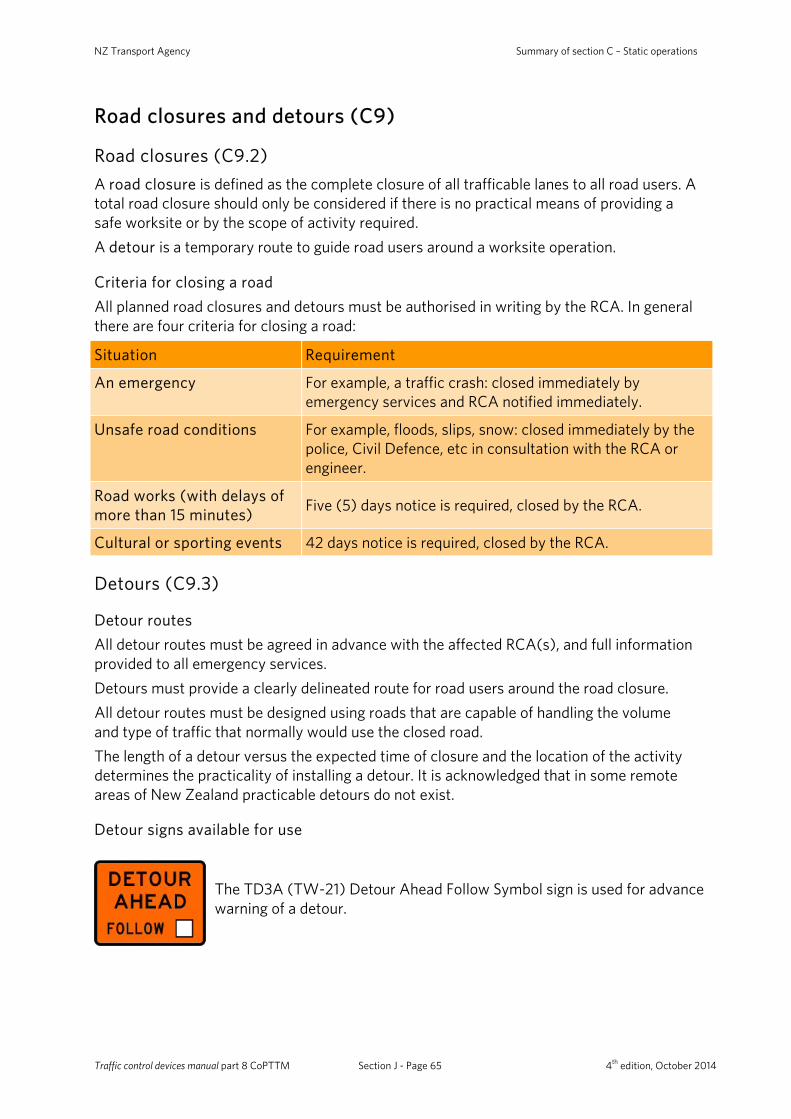
NZ Transport Agency Summary of section C – Static operations
Road closures and detours (C9)
Road closures (C9.2) A road closure is defined as the complete closure of all trafficable lanes to all road users. A total road closure should only be considered if there is no practical means of providing a safe worksite or by the scope of activity required. A detour is a temporary route to guide road users around a worksite operation.
Criteria for closing a road All planned road closures and detours must be authorised in writing by the RCA. In general there are four criteria for closing a road:
Situation Requirement
An emergency For example, a traffic crash: closed immediately by emergency services and RCA notified immediately.
Unsafe road conditions For example, floods, slips, snow: closed immediately by the police, Civil Defence, etc in consultation with the RCA or engineer.
Road works (with delays of more than 15 minutes) Five (5) days notice is required, closed by the RCA.
Cultural or sporting events 42 days notice is required, closed by the RCA.
Detours (C9.3)
Detour routes All detour routes must be agreed in advance with the affected RCA(s), and full information provided to all emergency services. Detours must provide a clearly delineated route for road users around the road closure. All detour routes must be designed using roads that are capable of handling the volume and type of traffic that normally would use the closed road. The length of a detour versus the expected time of closure and the location of the activity determines the practicality of installing a detour. It is acknowledged that in some remote areas of New Zealand practicable detours do not exist.
Detour signs available for use
The TD3A (TW-21) Detour Ahead Follow Symbol sign is used for advance warning of a detour.
Traffic control devices manual part 8 CoPTTM Section J - Page 65 4th edition, October 2014
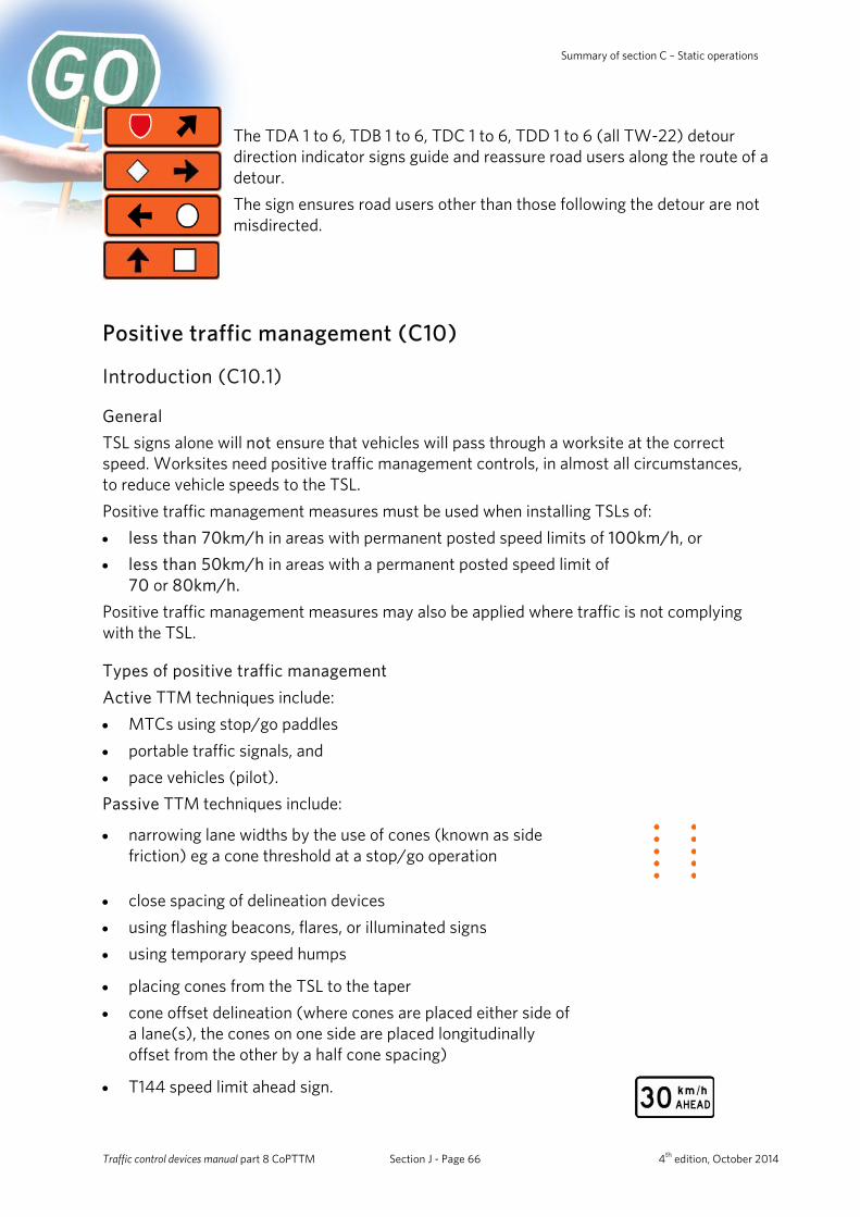
Summary of section C – Static operations
The TDA 1 to 6, TDB 1 to 6, TDC 1 to 6, TDD 1 to 6 (all TW-22) detour direction indicator signs guide and reassure road users along the route of a detour. The sign ensures road users other than those following the detour are not misdirected.
Positive traffic management (C10)
Introduction (C10.1)
General TSL signs alone will not ensure that vehicles will pass through a worksite at the correct speed. Worksites need positive traffic management controls, in almost all circumstances, to reduce vehicle speeds to the TSL. Positive traffic management measures must be used when installing TSLs of: • less than 70km/h in areas with permanent posted speed limits of 100km/h, or • less than 50km/h in areas with a permanent posted speed limit of
70 or 80km/h. Positive traffic management measures may also be applied where traffic is not complying with the TSL.
Types of positive traffic management Active TTM techniques include: • MTCs using stop/go paddles • portable traffic signals, and • pace vehicles (pilot). Passive TTM techniques include:
• narrowing lane widths by the use of cones (known as side friction) eg a cone threshold at a stop/go operation
• close spacing of delineation devices • using flashing beacons, flares, or illuminated signs • using temporary speed humps
• placing cones from the TSL to the taper • cone offset delineation (where cones are placed either side of
a lane(s), the cones on one side are placed longitudinally offset from the other by a half cone spacing)
• T144 speed limit ahead sign.
Traffic control devices manual part 8 CoPTTM Section J - Page 66 4th edition, October 2014
NZ Transport Agency Summary of section C – Static operations
Control of two-way two-lane roads reduced to one lane All two-way two-lane roads reduced to one lane require MTCs or portable traffic signals to manage traffic. Special exemption may be granted by the RCA for roads carrying less than 1000vpd, in which case the TL9L/TL9S or TL9B One Lane sign must be used in conjunction with RP51/RP22 Single Lane - Give Way and RP52 Single Lane - Priority signs. The use of MTCs during the hours of darkness and during times of poor visibility should be avoided.
Stop/go operations - manual traffic control (C10.2)
General Stop /go operations must not be used where two-way traffic flow can be maintained past a worksite
MTCs may be used for situations that include: • stopping traffic to avoid a hazard • allowing traffic from opposite directions to use one lane alternately (alternating flow) • stopping all road traffic to allow construction traffic to cross or for blasting, or tree work • slowing traffic where they need to travel very slowly, eg over new seal or in poor
visibility, and • giving road users verbal instructions or directions.
MTCs may not be the best option for long-term worksites. An MTC must receive a briefing from an STMS.
Equipment required MTCs must use stop/go paddles except in unforeseen emergency situations when flag or hand signals may be used.
Visibility of MTC MTCs should take particular care to ensure they are: • visible at all times and in particular at dawn or dusk, against low morning or evening
sun, when in shadow on a sunny day, or in dusty conditions • well lit at night • not obstructing a road user’s view of other signs and devices • not hidden by other signs and devices.
Mandatory 30km/h TSL (C10.2.5) Worksites controlled with MTCs must have a TSL of 30km/h. Note: If the permanent speed limit is 40km/h either 20km/h TSL may be used or the existing permanent speed limit of 40km/h may be retained. If the 40km/h permanent speed limit is retained, positive traffic management must be used to compensate for the extra speed. Positive traffic management must be used to ensure speeds of approaching traffic are reduced.
Traffic control devices manual part 8 CoPTTM Section J - Page 67 4th edition, October 2014
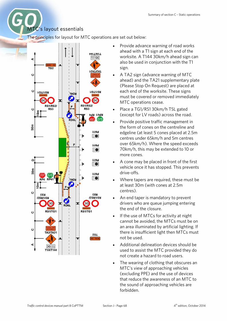
Summary of section C – Static operations
MTC’s layout essentials The principles for layout for MTC operations are set out below:
• Provide advance warning of road works ahead with a T1 sign at each end of the worksite. A T144 30km/h ahead sign can also be used in conjunction with the T1 sign.
• A TA2 sign (advance warning of MTC ahead) and the TA21 supplementary plate (Please Stop On Request) are placed at each end of the worksite. These signs must be covered or removed immediately MTC operations cease.
• Place a TG1/RS1 30km/h TSL gated (except for LV roads) across the road.
• Provide positive traffic management in the form of cones on the centreline and edgeline (at least 5 cones placed at 2.5m centres under 65km/h and 5m centres over 65km/h). Where the speed exceeds 70km/h, this may be extended to 10 or more cones.
• A cone may be placed in front of the first vehicle once it has stopped. This prevents drive-offs.
• Where tapers are required, these must be at least 30m (with cones at 2.5m centres).
• An end taper is mandatory to prevent drivers who are queue jumping entering the end of the closure.
• If the use of MTCs for activity at night cannot be avoided, the MTCs must be on an area illuminated by artificial lighting. If there is insufficient light then MTCs must not be used.
• Additional delineation devices should be used to assist the MTC provided they do not create a hazard to road users.
• The wearing of clothing that obscures an MTC’s view of approaching vehicles (excluding PPE) and the use of devices that reduce the awareness of an MTC to the sound of approaching vehicles are forbidden.
Traffic control devices manual part 8 CoPTTM Section J - Page 68 4th edition, October 2014

NZ Transport Agency Summary of section C – Static operations
Location of MTC MTCs must have a clear view of approaching road users for at least 120m. The STMS/TC must check that each MTC is stationed in the correct position. MTCs must stand facing oncoming traffic at the beginning of the cone taper on the left-hand shoulder or on the edge of the road and behind the cone threshold on the other lane. Note: Under no circumstances may MTCs stand or operate unprotected in a live lane. If they need to communicate to a road user, they should do so from the shoulder once their vehicle has stopped.
2.75m
RP41RP4
RD6L
RD6L
1st2nd
Minimum 5 cones at: 2.5m centres - less than 65km/h 5m centres - more than 65km/h
MTC with STOP/GO paddle on road shoulder located between 1st and
2nd cone
30m taper Cones at 2.5m
centres
Traffic control devices manual part 8 CoPTTM Section J - Page 69 4th edition, October 2014
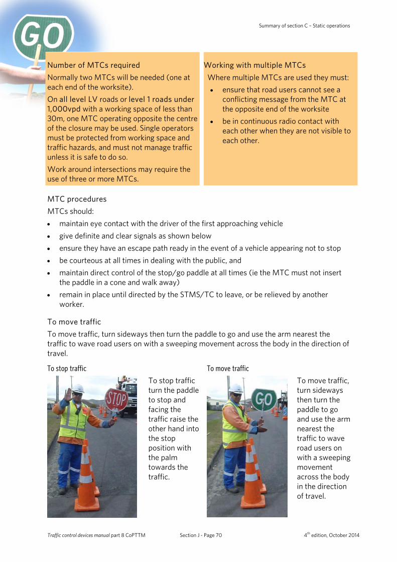
Summary of section C – Static operations
Number of MTCs required Normally two MTCs will be needed (one at each end of the worksite). On all level LV roads or level 1 roads under 1,000vpd with a working space of less than 30m, one MTC operating opposite the centre of the closure may be used. Single operators must be protected from working space and traffic hazards, and must not manage traffic unless it is safe to do so. Work around intersections may require the use of three or more MTCs.
Working with multiple MTCs Where multiple MTCs are used they must: • ensure that road users cannot see a
conflicting message from the MTC at the opposite end of the worksite
• be in continuous radio contact with each other when they are not visible to each other.
MTC procedures MTCs should: • maintain eye contact with the driver of the first approaching vehicle • give definite and clear signals as shown below • ensure they have an escape path ready in the event of a vehicle appearing not to stop • be courteous at all times in dealing with the public, and • maintain direct control of the stop/go paddle at all times (ie the MTC must not insert
the paddle in a cone and walk away) • remain in place until directed by the STMS/TC to leave, or be relieved by another
worker.
To move traffic To move traffic, turn sideways then turn the paddle to go and use the arm nearest the traffic to wave road users on with a sweeping movement across the body in the direction of travel.
To stop traffic
To stop traffic turn the paddle to stop and facing the traffic raise the other hand into the stop position with the palm towards the traffic.
To move traffic
To move traffic, turn sideways then turn the paddle to go and use the arm nearest the traffic to wave road users on with a sweeping movement across the body in the direction of travel.
Traffic control devices manual part 8 CoPTTM Section J - Page 70 4th edition, October 2014
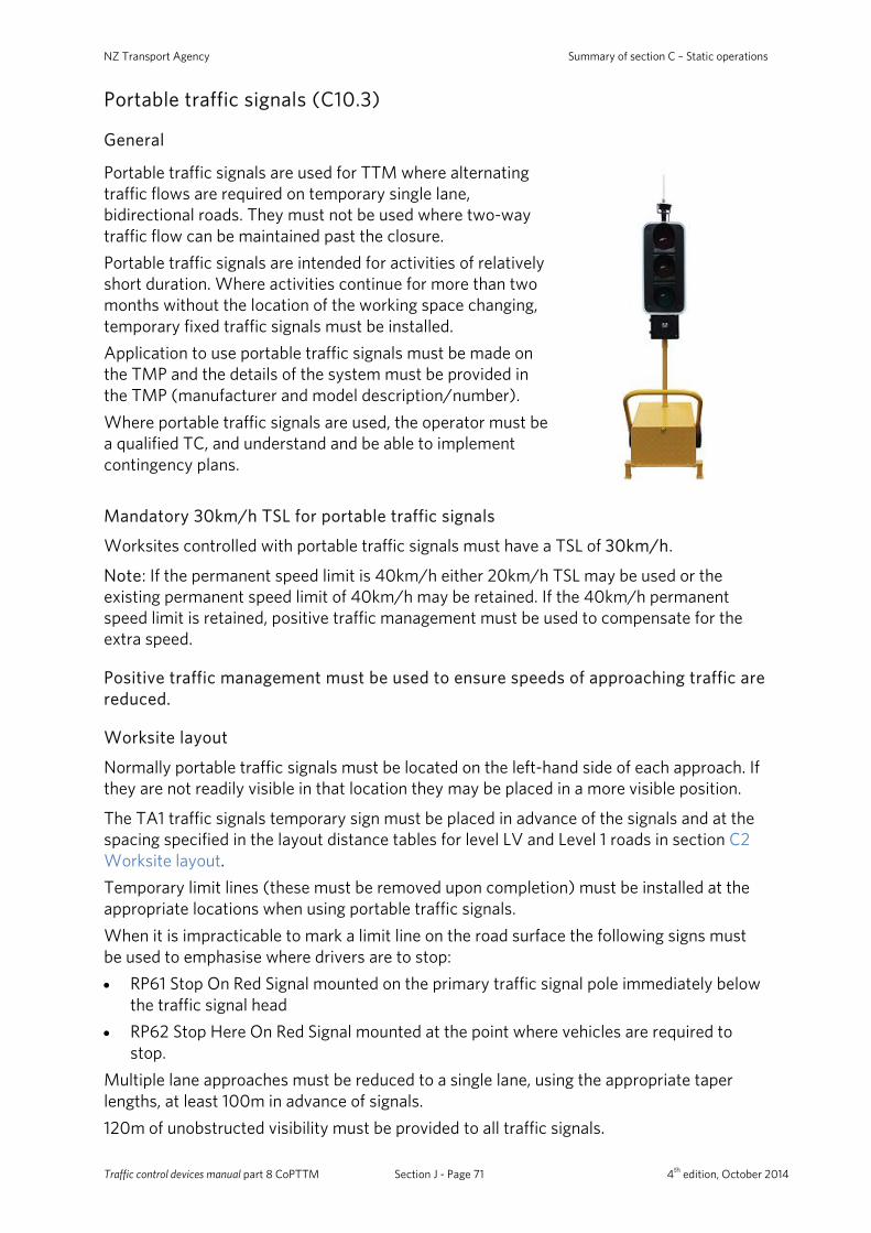
NZ Transport Agency Summary of section C – Static operations
Portable traffic signals (C10.3)
General
Portable traffic signals are used for TTM where alternating traffic flows are required on temporary single lane, bidirectional roads. They must not be used where two-way traffic flow can be maintained past the closure. Portable traffic signals are intended for activities of relatively short duration. Where activities continue for more than two months without the location of the working space changing, temporary fixed traffic signals must be installed. Application to use portable traffic signals must be made on the TMP and the details of the system must be provided in the TMP (manufacturer and model description/number). Where portable traffic signals are used, the operator must be a qualified TC, and understand and be able to implement contingency plans.
Mandatory 30km/h TSL for portable traffic signals
Worksites controlled with portable traffic signals must have a TSL of 30km/h.
Note: If the permanent speed limit is 40km/h either 20km/h TSL may be used or the existing permanent speed limit of 40km/h may be retained. If the 40km/h permanent speed limit is retained, positive traffic management must be used to compensate for the extra speed.
Positive traffic management must be used to ensure speeds of approaching traffic are reduced.
Worksite layout
Normally portable traffic signals must be located on the left-hand side of each approach. If they are not readily visible in that location they may be placed in a more visible position.
The TA1 traffic signals temporary sign must be placed in advance of the signals and at the spacing specified in the layout distance tables for level LV and Level 1 roads in section C2 Worksite layout. Temporary limit lines (these must be removed upon completion) must be installed at the appropriate locations when using portable traffic signals. When it is impracticable to mark a limit line on the road surface the following signs must be used to emphasise where drivers are to stop: • RP61 Stop On Red Signal mounted on the primary traffic signal pole immediately below
the traffic signal head • RP62 Stop Here On Red Signal mounted at the point where vehicles are required to
stop. Multiple lane approaches must be reduced to a single lane, using the appropriate taper lengths, at least 100m in advance of signals. 120m of unobstructed visibility must be provided to all traffic signals.
Traffic control devices manual part 8 CoPTTM Section J - Page 71 4th edition, October 2014
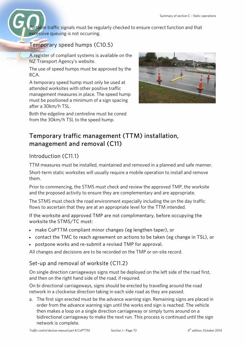
Summary of section C – Static operations
Portable traffic signals must be regularly checked to ensure correct function and that excessive queuing is not occurring.
Temporary speed humps (C10.5)
A register of compliant systems is available on the NZ Transport Agency’s website. The use of speed humps must be approved by the RCA. A temporary speed hump must only be used at attended worksites with other positive traffic management measures in place. The speed hump must be positioned a minimum of a sign spacing after a 30km/h TSL. Both the edgeline and centreline must be coned from the 30km/h TSL to the speed hump.
Temporary traffic management (TTM) installation, management and removal (C11)
Introduction (C11.1) TTM measures must be installed, maintained and removed in a planned and safe manner. Short-term static worksites will usually require a mobile operation to install and remove them.
Prior to commencing, the STMS must check and review the approved TMP, the worksite and the proposed activity to ensure they are complementary and are appropriate.
The STMS must check the road environment especially including the on the day traffic flows to ascertain that they are at an appropriate level for the TTM intended.
If the worksite and approved TMP are not complimentary, before occupying the worksite the STMS/TC must:
• make CoPTTM compliant minor changes (eg lengthen taper), or • contact the TMC to reach agreement on actions to be taken (eg change in TSL), or • postpone works and re-submit a revised TMP for approval. All changes and decisions are to be recorded on the TMP or on-site record.
Set-up and removal of worksite (C11.2) On single direction carriageways signs must be deployed on the left side of the road first, and then on the right hand side of the road, if required. On bi directional carriageways, signs should be erected by travelling around the road network in a clockwise direction taking in each side road as they are passed. a. The first sign erected must be the advance warning sign. Remaining signs are placed in
order from the advance warning sign until the works end sign is reached. The vehicle then makes a loop on a single direction carriageway or simply turns around on a bidirectional carriageway to make the next run. This process is continued until the sign network is complete.
Traffic control devices manual part 8 CoPTTM Section J - Page 72 4th edition, October 2014

NZ Transport Agency Summary of section C – Static operations
b. Tapers and delineation devices must only be placed once all signs have been installed. c. Before any construction equipment or materials are brought onto the worksite a drive
through check of the worksite must be made in all directions including all side roads.
The removal of TTM measures must be in the reverse order of establishment.
Installing signs on level LV and level 1 roads Vehicles used to install TTM equipment on level LV and level 1 roads must have amber flashing beacon(s) visible to all approaching traffic and signs:
either T1A and RD6R/L, or TV4 and RD6L/R.
If workers are not protected by another work vehicle then TTM equipment must be installed from the side of the work vehicle. Under no circumstances should signs be erected or any activity carried out by personnel behind a work vehicle exposed to oncoming traffic.
Installation of channelling and delineation devices Delineation devices are to be installed in straight lines or smooth curves, to give clear direction to the road users. Delineation devices can be installed and removed by personnel on foot.
Redundant TTM equipment All redundant TTM equipment must be removed from the site or placed in a safe secure location. Redundant equipment is defined as that TTM equipment not in current use for TTM. This includes TTM equipment not required when the site is left unattended. Redundant TTM signs, sign supports, sign bases and delineators may be stored on site provided that: • the equipment does not remain on-site and unused for a period greater than 48 hours • the equipment is stored in a safe location where it will not pose a hazard to any person
or property • STMSs identify and appropriately manage the site specific hazards as they apply to this
matter • the equipment must not be stored or placed on an open footpath or cycle way • the equipment must be stored at least 5m from edge line where no footpath exists or,
where one exists, in the back berm area (i.e. between footpath and boundary). Redundant TTM equipment must not be left standing nor deployed.
Traffic control devices manual part 8 CoPTTM Section J - Page 73 4th edition, October 2014
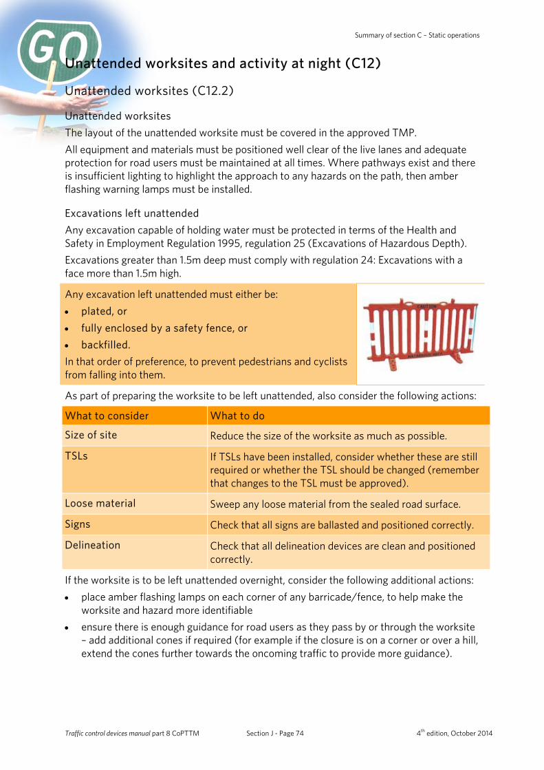
Summary of section C – Static operations
Unattended worksites and activity at night (C12)
Unattended worksites (C12.2)
Unattended worksites The layout of the unattended worksite must be covered in the approved TMP. All equipment and materials must be positioned well clear of the live lanes and adequate protection for road users must be maintained at all times. Where pathways exist and there is insufficient lighting to highlight the approach to any hazards on the path, then amber flashing warning lamps must be installed.
Excavations left unattended Any excavation capable of holding water must be protected in terms of the Health and Safety in Employment Regulation 1995, regulation 25 (Excavations of Hazardous Depth). Excavations greater than 1.5m deep must comply with regulation 24: Excavations with a face more than 1.5m high.
Any excavation left unattended must either be: • plated, or • fully enclosed by a safety fence, or • backfilled. In that order of preference, to prevent pedestrians and cyclists from falling into them.
As part of preparing the worksite to be left unattended, also consider the following actions:
What to consider What to do
Size of site Reduce the size of the worksite as much as possible.
TSLs If TSLs have been installed, consider whether these are still required or whether the TSL should be changed (remember that changes to the TSL must be approved).
Loose material Sweep any loose material from the sealed road surface.
Signs Check that all signs are ballasted and positioned correctly.
Delineation Check that all delineation devices are clean and positioned correctly.
If the worksite is to be left unattended overnight, consider the following additional actions: • place amber flashing lamps on each corner of any barricade/fence, to help make the
worksite and hazard more identifiable • ensure there is enough guidance for road users as they pass by or through the worksite
– add additional cones if required (for example if the closure is on a corner or over a hill, extend the cones further towards the oncoming traffic to provide more guidance).
Traffic control devices manual part 8 CoPTTM Section J - Page 74 4th edition, October 2014
NZ Transport Agency Summary of section C – Static operations
Activity at night (C12.4) Undertaking activity at night is effective in reducing delays to traffic because traffic volumes are lighter than during most daylight hours. Activity at night must be subject to careful additional planning and inspection. When planning night-time traffic management measures the STMS will need to consider that: • traffic density will be less and hence traffic speed may increase • road user’s visibility is reduced • road users awareness may be reduced • positive traffic management measures may be different • additional lighting for working spaces, safety zones, MTCs, pedestrian and cycle lane
detours, and for mobile working plant is required. These should always be chosen and mounted so that they direct light downward. Light sources that produce glare that could dazzle road users are not permitted, and
• Use of illuminated wands is optional and may only be used when overhead lighting for MTCs is provided.
Note: All signs must have a delineation device placed at the base of each sign on the traffic side.
Amber flashing warning lamps Where there is a hazard on a footpath or cycle lane, amber flashing warning lamps may be placed on any barricades and fences. A lamp may also be placed on each corner of the barricade/fence, to help make the worksite and hazard more identifiable.
Artificial lighting Lighting must not create a disabling glare for road users. A drive through the worksite from all approaches immediately after the lighting is installed to check for glare must be undertaken by the STMS/TC. Pedestrian and cyclist detours or temporary paths must be adequately lit, especially when the worksite is unattended.
Traffic control devices manual part 8 CoPTTM Section J - Page 75 4th edition, October 2014
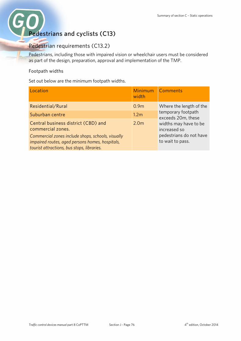
Summary of section C – Static operations
Pedestrians and cyclists (C13)
Pedestrian requirements (C13.2) Pedestrians, including those with impaired vision or wheelchair users must be considered as part of the design, preparation, approval and implementation of the TMP.
Footpath widths
Set out below are the minimum footpath widths.
Location Minimum width
Comments
Residential/Rural 0.9m Where the length of the temporary footpath exceeds 20m, these widths may have to be increased so pedestrians do not have to wait to pass.
Suburban centre 1.2m
Central business district (CBD) and commercial zones. Commercial zones include shops, schools, visually impaired routes, aged persons homes, hospitals, tourist attractions, bus stops, libraries.
2.0m
Traffic control devices manual part 8 CoPTTM Section J - Page 76 4th edition, October 2014
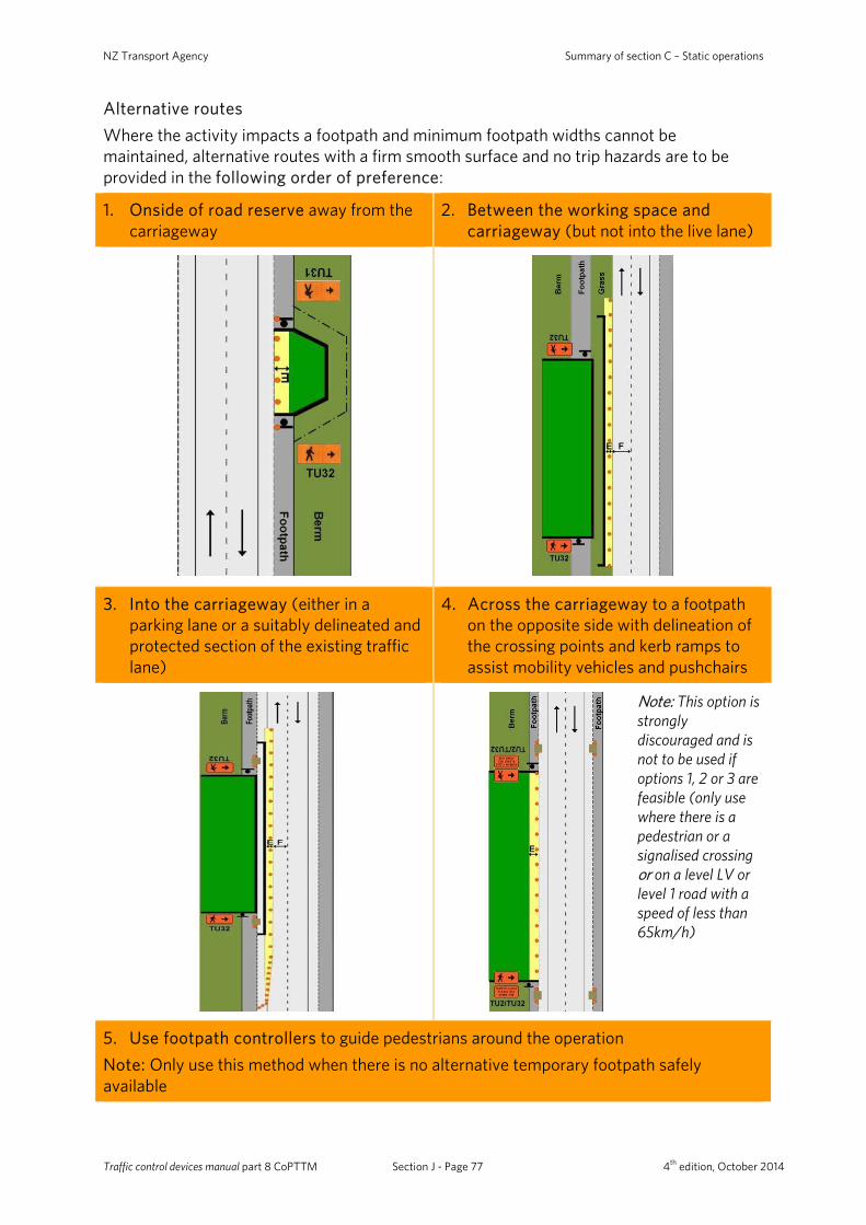
NZ Transport Agency Summary of section C – Static operations
Alternative routes Where the activity impacts a footpath and minimum footpath widths cannot be maintained, alternative routes with a firm smooth surface and no trip hazards are to be provided in the following order of preference:
1. Onside of road reserve away from the carriageway
2. Between the working space and carriageway (but not into the live lane)
3. Into the carriageway (either in a parking lane or a suitably delineated and protected section of the existing traffic lane)
4. Across the carriageway to a footpath on the opposite side with delineation of the crossing points and kerb ramps to assist mobility vehicles and pushchairs
Note: This option is strongly discouraged and is not to be used if options 1, 2 or 3 are feasible (only use where there is a pedestrian or a signalised crossing or on a level LV or level 1 road with a speed of less than 65km/h)
5. Use footpath controllers to guide pedestrians around the operation Note: Only use this method when there is no alternative temporary footpath safely available
Traffic control devices manual part 8 CoPTTM Section J - Page 77 4th edition, October 2014
Summary of section C – Static operations
Protecting pedestrians from the working space If pedestrians could otherwise gain access to the working space then the contractor must protect pedestrians by installing:
Option When used
Safety fences Long-term or unattended worksites where there are hazards remaining for example such as >50mm excavations or exposed cables.
Cones connected with cone bars
Attended worksites. Note: Cone bars are not recommended where heavy equipment (eg a digger) is being used. A safety fence is preferred in these cases.
Footpath diverted into carriageway If the footpath is to be diverted into the carriageway then the traffic side of the footpath must be delineated by either:
Option When used Lateral safety zone required with delineation
Barriers Long-term worksites. 0.5m
Safety fences • Long-term worksites. • Any unattended worksites.
1m
Cones connected with cone bars
Attended worksites on: • level LV roads • level 1 roads (except state highways)
1m
Ramps Kerb ramps and any other footway ramps must meet minimum footpath width requirements and be not steeper than one vertical in eight horizontal.
Signage for temporary paths and detours
Footpath closed and pedestrians are to be directed across the road to an alternative footpath
Use theTU2 Footpath Closed Please Use Other Side sign. Pedestrians must not be required to cross more than 2 lanes without a central pedestrian refuge. Note: This sign can only be erected on level LV and level 1 roads with a posted speed limit of less than 65km/h. Care must be taken when using this method above 50km/h.
When this sign is used, pedestrians must have the following minimum sight distance to approaching vehicles:
• 75m at 50km/h • 100m at 60km/h.
This sight distance must be shown in the TMP.
Traffic control devices manual part 8 CoPTTM Section J - Page 78 4th edition, October 2014
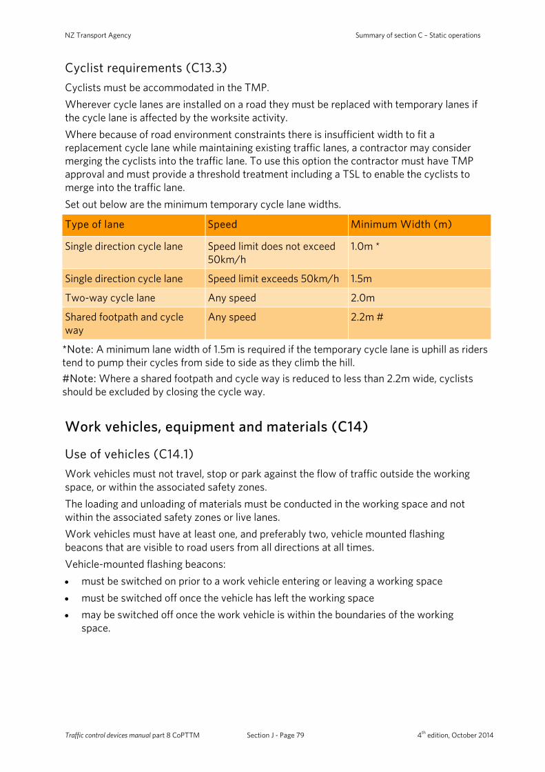
NZ Transport Agency Summary of section C – Static operations
Cyclist requirements (C13.3) Cyclists must be accommodated in the TMP. Wherever cycle lanes are installed on a road they must be replaced with temporary lanes if the cycle lane is affected by the worksite activity. Where because of road environment constraints there is insufficient width to fit a replacement cycle lane while maintaining existing traffic lanes, a contractor may consider merging the cyclists into the traffic lane. To use this option the contractor must have TMP approval and must provide a threshold treatment including a TSL to enable the cyclists to merge into the traffic lane. Set out below are the minimum temporary cycle lane widths.
Type of lane Speed Minimum Width (m)
Single direction cycle lane Speed limit does not exceed 50km/h
1.0m *
Single direction cycle lane Speed limit exceeds 50km/h 1.5m
Two-way cycle lane Any speed 2.0m
Shared footpath and cycle way
Any speed 2.2m #
*Note: A minimum lane width of 1.5m is required if the temporary cycle lane is uphill as riders tend to pump their cycles from side to side as they climb the hill. #Note: Where a shared footpath and cycle way is reduced to less than 2.2m wide, cyclists should be excluded by closing the cycle way.
Work vehicles, equipment and materials (C14)
Use of vehicles (C14.1) Work vehicles must not travel, stop or park against the flow of traffic outside the working space, or within the associated safety zones. The loading and unloading of materials must be conducted in the working space and not within the associated safety zones or live lanes. Work vehicles must have at least one, and preferably two, vehicle mounted flashing beacons that are visible to road users from all directions at all times. Vehicle-mounted flashing beacons: • must be switched on prior to a work vehicle entering or leaving a working space • must be switched off once the vehicle has left the working space • may be switched off once the work vehicle is within the boundaries of the working
space.
Traffic control devices manual part 8 CoPTTM Section J - Page 79 4th edition, October 2014
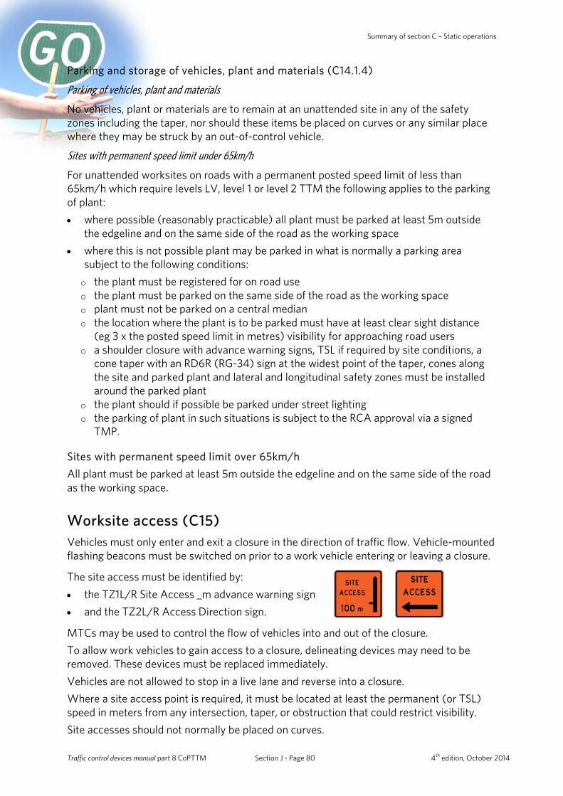
Summary of section C – Static operations
Parking and storage of vehicles, plant and materials (C14.1.4)
Parking of vehicles, plant and materials
No vehicles, plant or materials are to remain at an unattended site in any of the safety zones including the taper, nor should these items be placed on curves or any similar place where they may be struck by an out-of-control vehicle.
Sites with permanent speed limit under 65km/h
For unattended worksites on roads with a permanent posted speed limit of less than 65km/h which require levels LV, level 1 or level 2 TTM the following applies to the parking of plant: • where possible (reasonably practicable) all plant must be parked at least 5m outside
the edgeline and on the same side of the road as the working space • where this is not possible plant may be parked in what is normally a parking area
subject to the following conditions: o the plant must be registered for on road use o the plant must be parked on the same side of the road as the working space o plant must not be parked on a central median o the location where the plant is to be parked must have at least clear sight distance
(eg 3 x the posted speed limit in metres) visibility for approaching road users o a shoulder closure with advance warning signs, TSL if required by site conditions, a
cone taper with an RD6R (RG-34) sign at the widest point of the taper, cones along the site and parked plant and lateral and longitudinal safety zones must be installed around the parked plant
o the plant should if possible be parked under street lighting o the parking of plant in such situations is subject to the RCA approval via a signed
TMP.
Sites with permanent speed limit over 65km/h All plant must be parked at least 5m outside the edgeline and on the same side of the road as the working space.
Worksite access (C15) Vehicles must only enter and exit a closure in the direction of traffic flow. Vehicle-mounted flashing beacons must be switched on prior to a work vehicle entering or leaving a closure.
The site access must be identified by: • the TZ1L/R Site Access _m advance warning sign • and the TZ2L/R Access Direction sign.
MTCs may be used to control the flow of vehicles into and out of the closure. To allow work vehicles to gain access to a closure, delineating devices may need to be removed. These devices must be replaced immediately. Vehicles are not allowed to stop in a live lane and reverse into a closure. Where a site access point is required, it must be located at least the permanent (or TSL) speed in meters from any intersection, taper, or obstruction that could restrict visibility. Site accesses should not normally be placed on curves.
Traffic control devices manual part 8 CoPTTM Section J - Page 80 4th edition, October 2014
NZ Transport Agency Summary of section C – Static operations
Managing traffic queues (C16) Disruptions and delays and delays must be kept to a minimum. Note: Each RCA can set the timeframe acceptable for delays on their network. Many RCAs set a maximum timeframe of five minutes for delays to traffic. On roads with a permanent speed limit greater than 50km/h ensure advance warning signs are always located beyond the end of the maximum queue. This may mean extending the warning distance and sign spacing. Additional reminder signs may need to be erected closer to the closure when queues and/or visibility restrictions are excessive.
Delays TMPs must address any delays anticipated by worksite activities, including simple calculations to determine if delays of more than the maximum time allowed by the RCA are likely (normally five minutes). The RCA must be informed if delays of more than the maximum time limit are likely. They will decide whether to allow the predicted delays to be imposed, restrict the hours of your activity or periodically pause activity to allow queues to disperse. They will consider detours if substantial queuing is expected.
Delay calculations Delay calculations may be required by the RCA. Simple delay calculations can be done for closing one lane on a two-way two-lane road on the assumption that delays of more than five minutes occur when the following thresholds are exceeded: • if a lane more than 200m from an intersection carries more than 1000vph, and • if a lane within 200m of an intersection carries more than 500vph.
Delays can be assessed as follows:
1. Find the peak hourly traffic volume for each lane past the closure. (If the peak hourly traffic volume per lane is not known it can be estimated using half the AADT divided by 8).
2. Add the peak hourly traffic volume for both lanes. 3. If the total is greater than 500vph and the worksite is within 200m of an intersection
then five minute delays are expected. 4. If the total is greater than 1000vph and the worksite is further than 200m from an
intersection then five minute delays are expected. 5. If the thresholds in (3) or (4) are not exceeded then delays in excess of five minutes are
not expected.
Traffic control devices manual part 8 CoPTTM Section J - Page 81 4th edition, October 2014
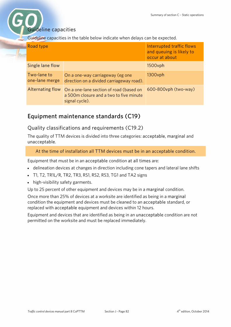
Summary of section C – Static operations
Guideline capacities Guideline capacities in the table below indicate when delays can be expected.
Road type Interrupted traffic flows and queuing is likely to occur at about
Single lane flow 1500vph
Two-lane to one-lane merge
On a one-way carriageway (eg one direction on a divided carriageway road).
1300vph
Alternating flow
On a one-lane section of road (based on a 500m closure and a two to five minute signal cycle).
600-800vph (two-way)
Equipment maintenance standards (C19)
Quality classifications and requirements (C19.2) The quality of TTM devices is divided into three categories: acceptable, marginal and unacceptable.
At the time of installation all TTM devices must be in an acceptable condition.
Equipment that must be in an acceptable condition at all times are: • delineation devices at changes in direction including cone tapers and lateral lane shifts • T1, T2, TR1L/R, TR2, TR3, RS1, RS2, RS3, TG1 and TA2 signs • high-visibility safety garments. Up to 25 percent of other equipment and devices may be in a marginal condition. Once more than 25% of devices at a worksite are identified as being in a marginal condition the equipment and devices must be cleaned to an acceptable standard, or replaced with acceptable equipment and devices within 12 hours. Equipment and devices that are identified as being in an unacceptable condition are not permitted on the worksite and must be replaced immediately.
Traffic control devices manual part 8 CoPTTM Section J - Page 82 4th edition, October 2014

NZ Transport Agency Summary of section C – Static operations
Condition Explanation
Acceptable Devices that meet the quality requirements as described in subsection C19.2 Quality classifications and requirements for this classification, and all other requirements such as design, size, colour, weight in the plans and specifications, must be considered to be acceptable for use as a traffic management device at worksites.
Marginal
The term ‘marginal’ means marginally acceptable or at the lower end of acceptability.
Devices that meet the quality criteria for marginal as described in subsection C19.2 Quality classifications and requirements for this classification, may remain on the worksite until 25 percent of the devices on the worksite are classified as marginal, or until it is determined that they have become unacceptable.
When devices in the marginal category reach 25 percent those devices must be cleaned or replaced to the acceptable standard within 12 hours.
Unacceptable Devices in this category must not be delivered to the worksite. When found at a worksite, they must be replaced or repaired immediately.
Traffic control devices manual part 8 CoPTTM Section J - Page 83 4th edition, October 2014
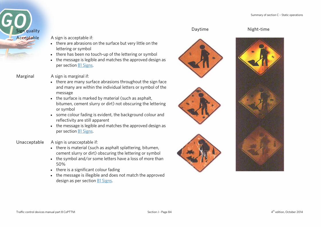
Summary of section C – Static operations
Sign quality Daytime Night-time
Acceptable
A sign is acceptable if: • there are abrasions on the surface but very little on the
lettering or symbol • there has been no touch-up of the lettering or symbol • the message is legible and matches the approved design as
per section B1 Signs.
Marginal
A sign is marginal if: • there are many surface abrasions throughout the sign face
and many are within the individual letters or symbol of the message
• the surface is marked by material (such as asphalt, bitumen, cement slurry or dirt) not obscuring the lettering or symbol
• some colour fading is evident, the background colour and reflectivity are still apparent
• the message is legible and matches the approved design as per section B1 Signs.
Unacceptable
A sign is unacceptable if: • there is material (such as asphalt splattering, bitumen,
cement slurry or dirt) obscuring the lettering or symbol • the symbol and/or some letters have a loss of more than
50% • there is a significant colour fading • the message is illegible and does not match the approved
design as per section B1 Signs.
Traffic control devices manual part 8 CoPTTM Section J - Page 84 4th edition, October 2014

NZ Transport Agency Summary of section C – Static operations
Cone quality Daytime Night-time
Acceptable
A cone is acceptable if: • the shape of the delineation device remains clearly
identifiable with no significant distortion and is free standing in its normal position
• the surface is free of punctures and abrasions • the surface is free of material (such as asphalt, cement
slurry or other material) and will readily clean-up by washing
• the reflective bands have little or no loss of reflectivity with only minor tears and scratches.
Marginal
A cone is marginal if: • the surface is marked by material (such as asphalt, bitumen,
cement slurry or dirt) and cannot be readily cleaned • the reflective bands have numerous tears and scratches • the reflective bands are largely free of residue.
Unacceptable
A cone is unacceptable if: • punctures and large areas of staining (due to materials such
as asphalt, bitumen, cement slurry or dirt) make the device an unlikely candidate for improvement
• there is a significant area of missing or stained reflective material.
Traffic control devices manual part 8 CoPTTM Section J - Page 85 4th edition, October 2014
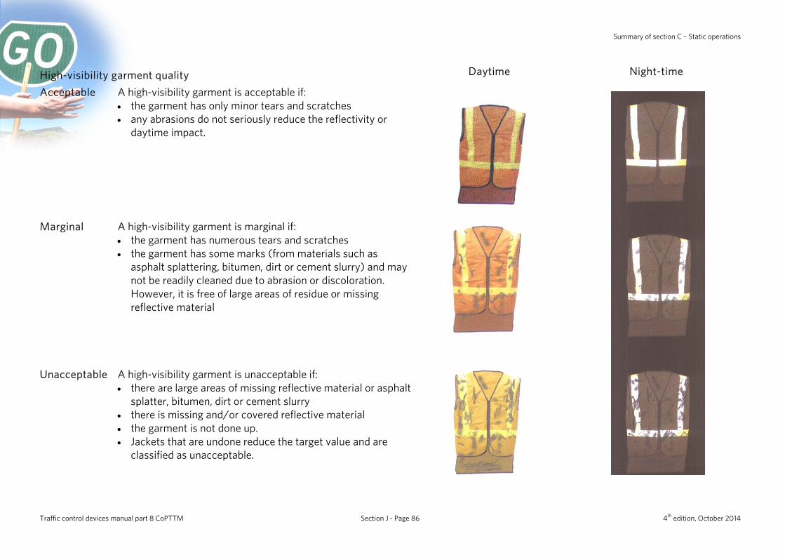
Summary of section C – Static operations
High-visibility garment quality Daytime Night-time
Acceptable
A high-visibility garment is acceptable if: • the garment has only minor tears and scratches • any abrasions do not seriously reduce the reflectivity or
daytime impact.
Marginal
A high-visibility garment is marginal if: • the garment has numerous tears and scratches • the garment has some marks (from materials such as
asphalt splattering, bitumen, dirt or cement slurry) and may not be readily cleaned due to abrasion or discoloration. However, it is free of large areas of residue or missing reflective material
Unacceptable
A high-visibility garment is unacceptable if: • there are large areas of missing reflective material or asphalt
splatter, bitumen, dirt or cement slurry • there is missing and/or covered reflective material • the garment is not done up. • Jackets that are undone reduce the target value and are
classified as unacceptable.
Traffic control devices manual part 8 CoPTTM Section J - Page 86 4th edition, October 2014
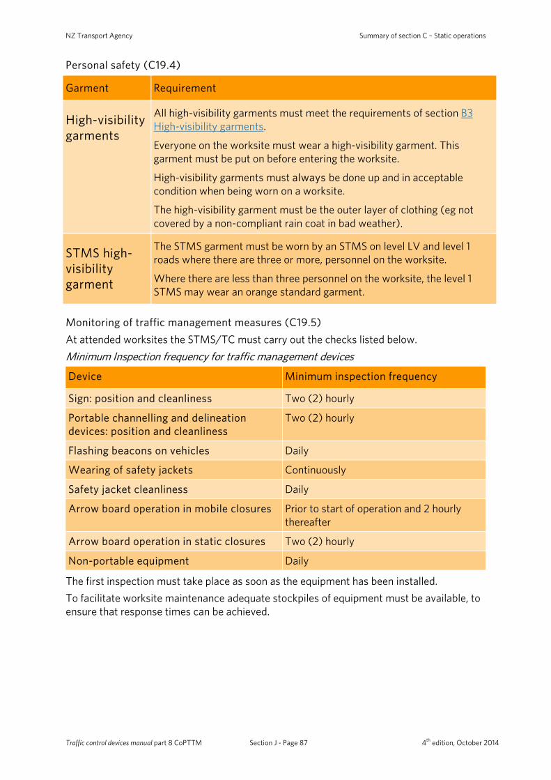
NZ Transport Agency Summary of section C – Static operations
Personal safety (C19.4)
Garment Requirement
High-visibility garments
All high-visibility garments must meet the requirements of section B3 High-visibility garments.
Everyone on the worksite must wear a high-visibility garment. This garment must be put on before entering the worksite.
High-visibility garments must always be done up and in acceptable condition when being worn on a worksite.
The high-visibility garment must be the outer layer of clothing (eg not covered by a non-compliant rain coat in bad weather).
STMS high-visibility garment
The STMS garment must be worn by an STMS on level LV and level 1 roads where there are three or more, personnel on the worksite.
Where there are less than three personnel on the worksite, the level 1 STMS may wear an orange standard garment.
Monitoring of traffic management measures (C19.5) At attended worksites the STMS/TC must carry out the checks listed below. Minimum Inspection frequency for traffic management devices
Device Minimum inspection frequency
Sign: position and cleanliness Two (2) hourly
Portable channelling and delineation devices: position and cleanliness
Two (2) hourly
Flashing beacons on vehicles Daily
Wearing of safety jackets Continuously
Safety jacket cleanliness Daily
Arrow board operation in mobile closures Prior to start of operation and 2 hourly thereafter
Arrow board operation in static closures Two (2) hourly
Non-portable equipment Daily
The first inspection must take place as soon as the equipment has been installed. To facilitate worksite maintenance adequate stockpiles of equipment must be available, to ensure that response times can be achieved.
Traffic control devices manual part 8 CoPTTM Section J - Page 87 4th edition, October 2014
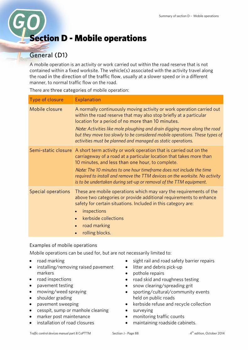
Summary of section D – Mobile operations
Section D - Mobile operations
General (D1) A mobile operation is an activity or work carried out within the road reserve that is not contained within a fixed worksite. The vehicle(s) associated with the activity travel along the road in the direction of the traffic flow, usually at a slower speed or in a different manner, to normal traffic flow on the road. There are three categories of mobile operation:
Type of closure Explanation
Mobile closure A normally continuously moving activity or work operation carried out within the road reserve that may also stop briefly at a particular location for a period of no more than 10 minutes. Note: Activities like mole ploughing and drain digging move along the road but they move too slowly to be considered mobile operations. These types of activities must be planned and managed as static operations.
Semi-static closure A short term activity or work operation that is carried out on the carriageway of a road at a particular location that takes more than 10 minutes, and less than one hour, to complete. Note: The 10 minutes to one hour timeframe does not include the time required to install and remove the TTM devices on the worksite. No activity is to be undertaken during set-up or removal of the TTM equipment.
Special operations These are mobile operations which may vary the requirements of the above two categories or provide additional requirements to enhance safety for certain situations. Included in this category are: • inspections • kerbside collections • road marking • rolling blocks.
Examples of mobile operations Mobile operations can be used for, but are not necessarily limited to: • road marking • installing/removing raised pavement
markers • road inspections • pavement testing • mowing/weed spraying • shoulder grading • pavement sweeping • cesspit, sump or manhole cleaning • marker post maintenance • installation of road closures
• sight rail and road safety barrier repairs • litter and debris pick-up • pothole repairs • road skid and roughness testing • snow clearing/spreading grit • sporting/cultural/community events
held on public roads • kerbside refuse and recycle collection • surveying • monitoring traffic counts • maintaining roadside cabinets.
Traffic control devices manual part 8 CoPTTM Section J - Page 88 4th edition, October 2014
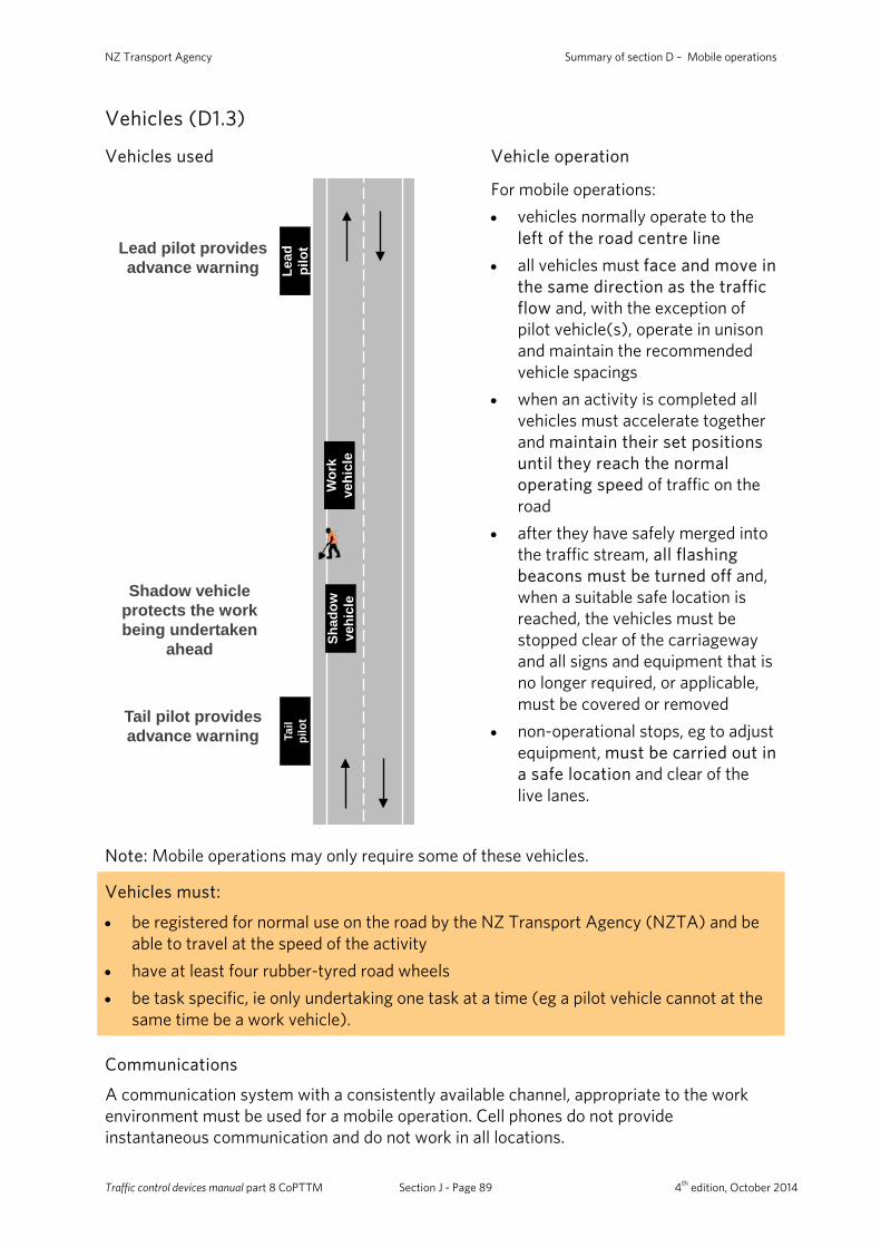
NZ Transport Agency Summary of section D – Mobile operations
Vehicles (D1.3)
Vehicles used Vehicle operation
Shadow vehicle protects the work being undertaken
ahead
Lead pilot provides advance warning
Tail pilot provides advance warning
Wor
k ve
hicl
e
Lead
pi
lot
Shad
ow
vehi
cle
Tail
pilo
t
For mobile operations: • vehicles normally operate to the
left of the road centre line • all vehicles must face and move in
the same direction as the traffic flow and, with the exception of pilot vehicle(s), operate in unison and maintain the recommended vehicle spacings
• when an activity is completed all vehicles must accelerate together and maintain their set positions until they reach the normal operating speed of traffic on the road
• after they have safely merged into the traffic stream, all flashing beacons must be turned off and, when a suitable safe location is reached, the vehicles must be stopped clear of the carriageway and all signs and equipment that is no longer required, or applicable, must be covered or removed
• non-operational stops, eg to adjust equipment, must be carried out in a safe location and clear of the live lanes.
Note: Mobile operations may only require some of these vehicles.
Vehicles must:
• be registered for normal use on the road by the NZ Transport Agency (NZTA) and be able to travel at the speed of the activity
• have at least four rubber-tyred road wheels • be task specific, ie only undertaking one task at a time (eg a pilot vehicle cannot at the
same time be a work vehicle).
Communications
A communication system with a consistently available channel, appropriate to the work environment must be used for a mobile operation. Cell phones do not provide instantaneous communication and do not work in all locations.
Traffic control devices manual part 8 CoPTTM Section J - Page 89 4th edition, October 2014
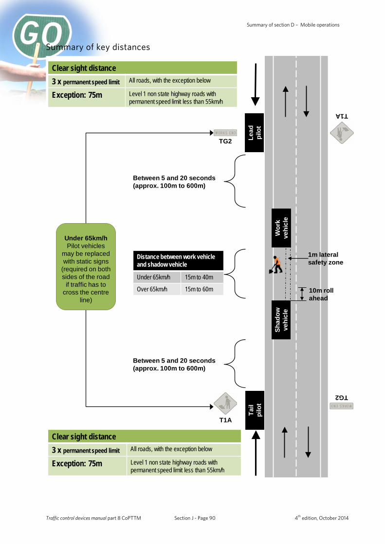
Summary of section D – Mobile operations
Summary of key distances
Between 5 and 20 seconds (approx. 100m to 600m)
Clear sight distance3 x permanent speed limit All roads, with the exception below
Exception: 75m Level 1 non state highway roads with permanent speed limit less than 55km/h
Distance between work vehicle and shadow vehicle
Under 65km/h 15m to 40m
Over 65km/h 15m to 60m 10m roll ahead
Clear sight distance3 x permanent speed limit All roads, with the exception below
Exception: 75m Level 1 non state highway roads with permanent speed limit less than 55km/h
Between 5 and 20 seconds (approx. 100m to 600m)
1m lateral safety zone
Wor
k ve
hicl
e
Lead
pi
lot
Shad
ow
vehi
cle
Tail
pilo
t
Under 65km/h Pilot vehicles
may be replaced with static signs
(required on both sides of the road
if traffic has to cross the centre
line)
T1A
TG2
T1A
TG2
Traffic control devices manual part 8 CoPTTM Section J - Page 90 4th edition, October 2014
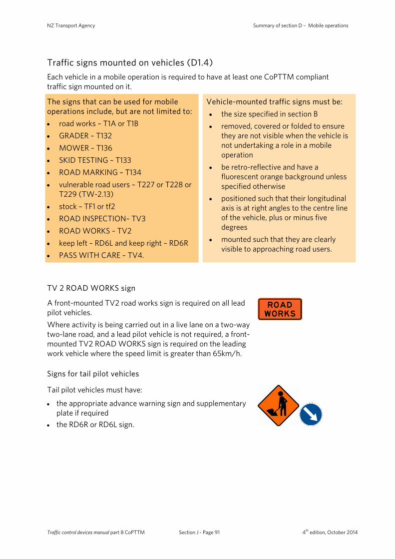
NZ Transport Agency Summary of section D – Mobile operations
Traffic signs mounted on vehicles (D1.4) Each vehicle in a mobile operation is required to have at least one CoPTTM compliant traffic sign mounted on it.
The signs that can be used for mobile operations include, but are not limited to: • road works – T1A or T1B • GRADER – T132 • MOWER – T136 • SKID TESTING – T133 • ROAD MARKING – T134 • vulnerable road users – T227 or T228 or
T229 (TW-2.13) • stock – TF1 or tf2 • ROAD INSPECTION– TV3 • ROAD WORKS – TV2 • keep left – RD6L and keep right – RD6R • PASS WITH CARE – TV4.
Vehicle-mounted traffic signs must be: • the size specified in section B • removed, covered or folded to ensure
they are not visible when the vehicle is not undertaking a role in a mobile operation
• be retro-reflective and have a fluorescent orange background unless specified otherwise
• positioned such that their longitudinal axis is at right angles to the centre line of the vehicle, plus or minus five degrees
• mounted such that they are clearly visible to approaching road users.
TV 2 ROAD WORKS sign
A front-mounted TV2 road works sign is required on all lead pilot vehicles. Where activity is being carried out in a live lane on a two-way two-lane road, and a lead pilot vehicle is not required, a front-mounted TV2 ROAD WORKS sign is required on the leading work vehicle where the speed limit is greater than 65km/h.
Signs for tail pilot vehicles
Tail pilot vehicles must have:
• the appropriate advance warning sign and supplementary plate if required
• the RD6R or RD6L sign.
Traffic control devices manual part 8 CoPTTM Section J - Page 91 4th edition, October 2014
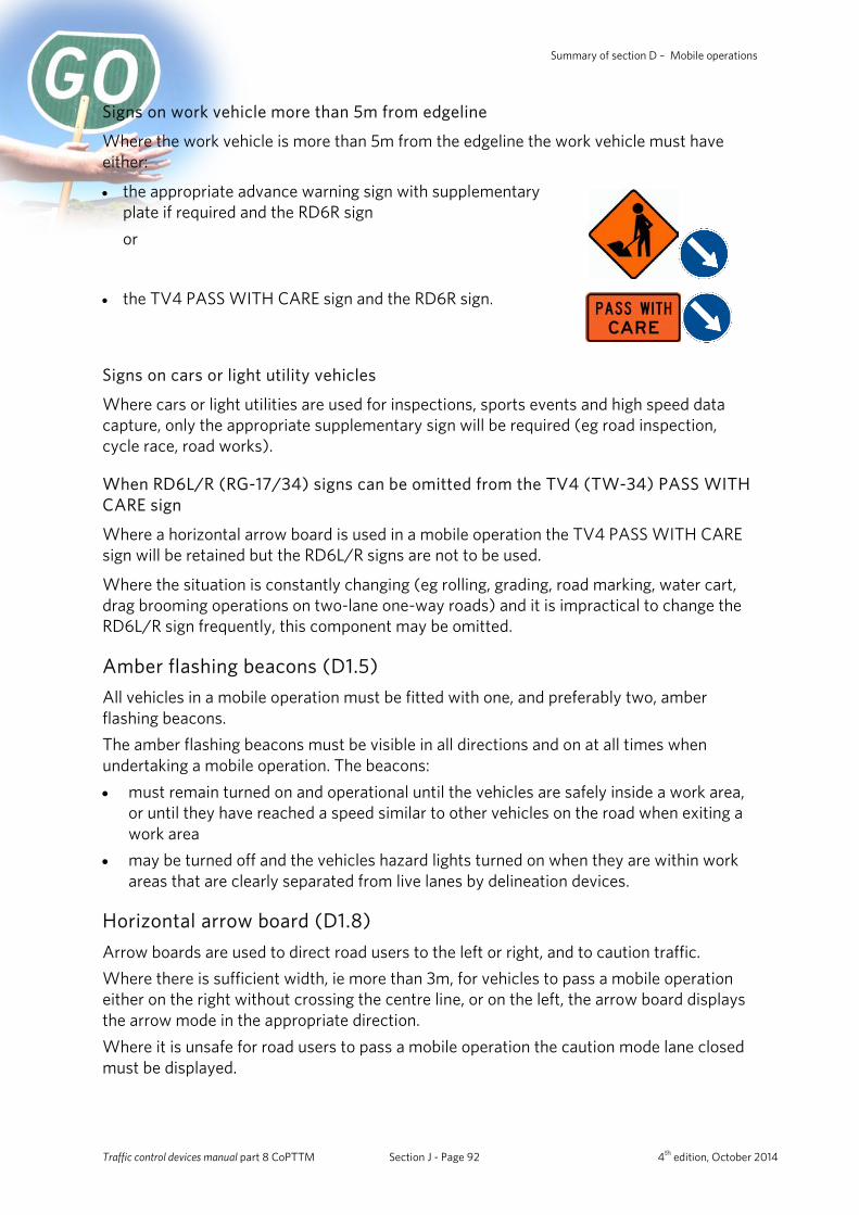
Summary of section D – Mobile operations
Signs on work vehicle more than 5m from edgeline
Where the work vehicle is more than 5m from the edgeline the work vehicle must have either:
• the appropriate advance warning sign with supplementary plate if required and the RD6R sign or
• the TV4 PASS WITH CARE sign and the RD6R sign.
Signs on cars or light utility vehicles
Where cars or light utilities are used for inspections, sports events and high speed data capture, only the appropriate supplementary sign will be required (eg road inspection, cycle race, road works).
When RD6L/R (RG-17/34) signs can be omitted from the TV4 (TW-34) PASS WITH CARE sign
Where a horizontal arrow board is used in a mobile operation the TV4 PASS WITH CARE sign will be retained but the RD6L/R signs are not to be used.
Where the situation is constantly changing (eg rolling, grading, road marking, water cart, drag brooming operations on two-lane one-way roads) and it is impractical to change the RD6L/R sign frequently, this component may be omitted.
Amber flashing beacons (D1.5) All vehicles in a mobile operation must be fitted with one, and preferably two, amber flashing beacons. The amber flashing beacons must be visible in all directions and on at all times when undertaking a mobile operation. The beacons: • must remain turned on and operational until the vehicles are safely inside a work area,
or until they have reached a speed similar to other vehicles on the road when exiting a work area
• may be turned off and the vehicles hazard lights turned on when they are within work areas that are clearly separated from live lanes by delineation devices.
Horizontal arrow board (D1.8) Arrow boards are used to direct road users to the left or right, and to caution traffic. Where there is sufficient width, ie more than 3m, for vehicles to pass a mobile operation either on the right without crossing the centre line, or on the left, the arrow board displays the arrow mode in the appropriate direction. Where it is unsafe for road users to pass a mobile operation the caution mode lane closed must be displayed.
Traffic control devices manual part 8 CoPTTM Section J - Page 92 4th edition, October 2014
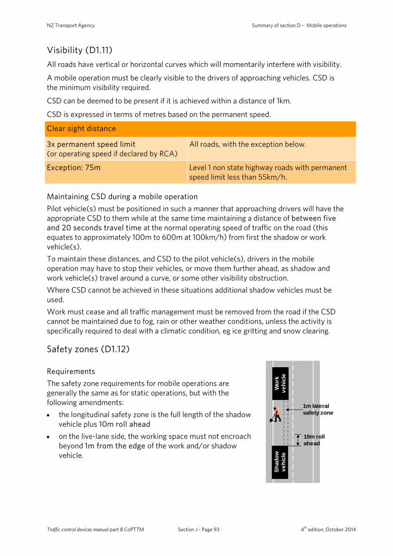
NZ Transport Agency Summary of section D – Mobile operations
Visibility (D1.11) All roads have vertical or horizontal curves which will momentarily interfere with visibility.
A mobile operation must be clearly visible to the drivers of approaching vehicles. CSD is the minimum visibility required.
CSD can be deemed to be present if it is achieved within a distance of 1km.
CSD is expressed in terms of metres based on the permanent speed.
Clear sight distance
3x permanent speed limit (or operating speed if declared by RCA)
All roads, with the exception below.
Exception: 75m Level 1 non state highway roads with permanent speed limit less than 55km/h.
Maintaining CSD during a mobile operation Pilot vehicle(s) must be positioned in such a manner that approaching drivers will have the appropriate CSD to them while at the same time maintaining a distance of between five and 20 seconds travel time at the normal operating speed of traffic on the road (this equates to approximately 100m to 600m at 100km/h) from first the shadow or work vehicle(s). To maintain these distances, and CSD to the pilot vehicle(s), drivers in the mobile operation may have to stop their vehicles, or move them further ahead, as shadow and work vehicle(s) travel around a curve, or some other visibility obstruction. Where CSD cannot be achieved in these situations additional shadow vehicles must be used. Work must cease and all traffic management must be removed from the road if the CSD cannot be maintained due to fog, rain or other weather conditions, unless the activity is specifically required to deal with a climatic condition, eg ice gritting and snow clearing.
Safety zones (D1.12)
Requirements The safety zone requirements for mobile operations are generally the same as for static operations, but with the following amendments: • the longitudinal safety zone is the full length of the shadow
vehicle plus 10m roll ahead • on the live-lane side, the working space must not encroach
beyond 1m from the edge of the work and/or shadow vehicle.
10m roll ahead
1m lateral safety zone
Wor
k ve
hicl
e
Shad
ow
vehi
cle
Traffic control devices manual part 8 CoPTTM Section J - Page 93 4th edition, October 2014
Summary of section D – Mobile operations
Personnel on foot (D1.13) The number of personnel on foot required for a mobile operation must be kept to the absolute minimum necessary to complete the work. For safety reasons it is desirable that personnel on foot do not enter a live lane unless protected by a shadow vehicle. Personnel on foot must keep within the working space and safety zones of the worksite. Only under emergency circumstances and with the utmost care should anyone enter a live lane.
Work vehicles (D2) A work vehicle is a vehicle carrying out activity adjacent to the road, or on the carriageway, or supporting personnel on foot. When a mobile operation or semi-static activity contains more than one work vehicle (and there is no-one on foot) the recommended distance between each work vehicle is 50m.
Pilot vehicles (D3) Pilot vehicles are not required on level LV and level 1 roads with permanent speed limits less than 65km/h.
Static advance warning signs must be installed on the road when a pilot vehicle is not used.
Pilot vehicles must be positioned as far to the left as practicable and, if possible, on the shoulder and clear of any live lanes. This position must also ensure that road users approaching from the opposite direction: • have at least forward CSD to the lead pilot vehicle • will encounter first work vehicle between five and 20 seconds travel time at the normal
speed of traffic on the road (this equates to approximately 100m to 600m at 100km/h) after passing the pilot vehicle.
Pilot vehicles are not required when the work vehicle(s) operates in excess of 80 percent of the permanent or operating speed. This is to be recorded and approved in the TMP. Static signing is not required in these situations.
Traffic control devices manual part 8 CoPTTM Section J - Page 94 4th edition, October 2014

NZ Transport Agency Summary of section D – Mobile operations
Lead pilot vehicles (D3.2) A lead pilot vehicle must be used on two-way roads with permanent speed limits greater than 65km/h when: • the length of road with visibility less than CSD is more than one 1km, or • the operation crosses the centre line.
A lead pilot vehicle is not required for snow clearing or ice gritting operations.
A lead pilot vehicle is not required for the inspection activities described in subsection D7.6 Inspections and non-invasive works when the vehicle used is not travelling slower than normal traffic and, if stopped, is parked clear of the live lane. A lead pilot vehicle is not required on one way or multi-lane divided roads.
Tail pilot vehicles (D3.3) A tail pilot vehicle is not required on level LV and level 1 roads where the permanent speed limit is greater than 65km/h and where the work vehicle(s) is: • within 5m of the edgeline, • is not on the carriageway, and • CSD to the work vehicle(s) is available at all times. In these situations the appropriate road works signs must be erected to warn road users of the mobile operation on the road ahead. These signs must be erected at spacings no greater than 4km. A TG2 WORKS END sign must be erected at each end of the mobile operation worksite. A tail pilot vehicle is not necessary on level LV and level 1 roads with permanent speed limits greater than 65km/h for the Inspection Activities described in section D7 Special mobile operation, when the inspection vehicle is: • not travelling slower than the normal operating speed of traffic on the road, and • if stopped, is parked clear of the live lane.
Traffic control devices manual part 8 CoPTTM Section J - Page 95 4th edition, October 2014
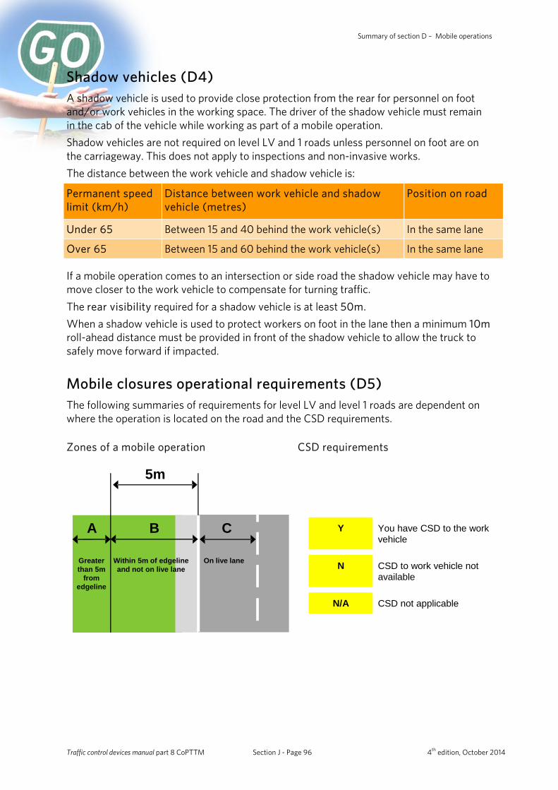
Summary of section D – Mobile operations
Shadow vehicles (D4) A shadow vehicle is used to provide close protection from the rear for personnel on foot and/or work vehicles in the working space. The driver of the shadow vehicle must remain in the cab of the vehicle while working as part of a mobile operation. Shadow vehicles are not required on level LV and 1 roads unless personnel on foot are on the carriageway. This does not apply to inspections and non-invasive works. The distance between the work vehicle and shadow vehicle is:
Permanent speed limit (km/h)
Distance between work vehicle and shadow vehicle (metres)
Position on road
Under 65 Between 15 and 40 behind the work vehicle(s) In the same lane
Over 65 Between 15 and 60 behind the work vehicle(s) In the same lane
If a mobile operation comes to an intersection or side road the shadow vehicle may have to move closer to the work vehicle to compensate for turning traffic. The rear visibility required for a shadow vehicle is at least 50m. When a shadow vehicle is used to protect workers on foot in the lane then a minimum 10m roll-ahead distance must be provided in front of the shadow vehicle to allow the truck to safely move forward if impacted.
Mobile closures operational requirements (D5) The following summaries of requirements for level LV and level 1 roads are dependent on where the operation is located on the road and the CSD requirements.
Zones of a mobile operation CSD requirements
5m
A B C
Greater than 5m
from edgeline
Within 5m of edgeline and not on live lane
On live lane
Y You have CSD to the work vehicle
N CSD to work vehicle not available
N/A CSD not applicable
Traffic control devices manual part 8 CoPTTM Section J - Page 96 4th edition, October 2014
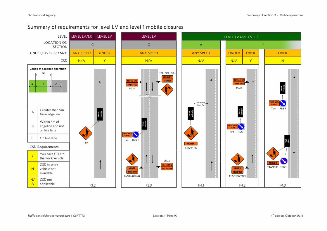
NZ Transport Agency Summary of section D – Mobile operations
Summary of requirements for level LV and level 1 mobile closures
LEVEL LEVEL LV/LR LEVEL LV LEVEL LV LEVEL LV and LEVEL 1 LOCATION ON
SECTION C C A B
UNDER/OVER 65KM/H ANY SPEED UNDER ANY SPEED ANY SPEED UNDER OVER OVER
CSD N/A Y N/A N/A N/A Y N
T1A
Wor
k ve
hicl
eW
ork
vehi
cle
TG32
TG32
TV4 RD6R
MOWERNext 4km
T1A/T136/T121
MOWERNext 4km
T1A/T136/T121
Wor
k ve
hicl
e
MOWER
T1A/T136
Greater than 5m
Wor
k ve
hicl
eW
ork
vehi
cle
MOWERNext 4km
T1A/T136/T121
TG32
TV4 RD6R
Wor
k ve
hicl
e
RD6RMOWER
T1A/T136
TV4 RD6R
Tail
pilo
t
Wor
k ve
hicl
e
A Greater than 5m from edgeline
B Within 5m of edgeline and not on live lane
C On live lane
CSD Requirements
Y You have CSD to the work vehicle
N CSD to work vehicle not available
N/A
CSD not applicable F3.2 F3.3 F4.1 F4.2 F4.3
Zones of a mobile operation5m
A B C
Traffic control devices manual part 8 CoPTTM Section J - Page 97 4th edition, October 2014
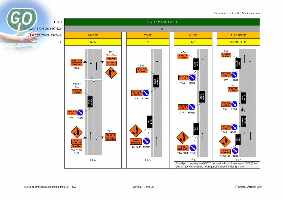
Summary of section D – Mobile operations
LEVEL LEVEL LV and LEVEL 1
LOCATION ON SECTION C
UNDER/OVER 65KM/H UNDER OVER OVER ANY SPEED
CSD N/A Y N AS NOTED
TG32
TV2
TG32
TV4 RD6R
Wor
k ve
hicl
e
Optional
Next 4km
T1A/T137/T121
Next 4kmT1A/T137/
T121
RD6R
TV2
TV4 RD6R
Wor
k ve
hicl
e
T1A/T134Ta
ilpi
lot
RD6R
TV2
TV4 RD6R
TV4 RD6R
Lead
pi
lot
Wor
k ve
hicl
e
Tail
pilo
t
T1A/T134
T1A/T134 RD6R
TV2
TV4 RD6R
TV4 RD6R
Wor
k ve
hicl
e
Lead
pi
lot
Shad
ow
vehi
cle
Tail
pilo
t
TV4 RD6R
TV2
F4.4 F4.5 F4.6 F4.7
Lead pilot only required if CSD not available for 1km or more. TV2 (TW-26) on lead work vehicle not required if speed under 65km/h.
Traffic control devices manual part 8 CoPTTM Section J - Page 98 4th edition, October 2014

NZ Transport Agency Summary of section D – Mobile operations
Semi-static closures (D6) A semi-static closure is a short-term operation on the carriageway of the road that is more than 10 minutes and less than one hour in duration. The 10 minutes to 60 minutes timeframe applies only to the working period and does not include the time required to install and remove the TTM devices on the worksite. Where the activity cannot be completed within one hour it becomes a static closure, by definition.
Semi-static closures are permitted on all one-way multi-lane roads.
Semi-static closures are not permitted on two-lane two-way roads. Semi static closures are not permitted where traffic is forced to cross the centre line. The flush median must not be used as a traffic lane for semi-static closures. However, semi-static closures may be used on two-lane two-way roads where the closure occupies the painted flush median.
The visibility, vehicle spacing and signing requirements for a semi-static closure on the carriageway of a road are exactly the same as those for an equivalent mobile closure in the same situation. In addition, the following requirements also apply to semi-static closures: • advance warning signs must be placed in advance of the closure • cones must be placed between the shadow vehicle and the work vehicle(s) • a cone taper must also be installed at the rear of the shadow vehicle • cone spacings must conform to the requirements given in the appropriate layout
distance table.
On one-way multi-lane roads
On one-way multi-lane roads T1A or T1B type road works signs must be placed in advance of the closure and on both sides of the carriageway.
If a tail pilot vehicle is being used, the advance warning sign mounted on the tail pilot vehicle performs this function for one side of the road and a static sign is erected on the other side of the road.
For two-way two-lane roads
For two-way two-lane roads (with painted flush median), static T1A or T1B type signs must be placed at each end of the closure.
Side roads
When stopped to carry out a semi-static operation with a side road between the tail pilot and the shadow work vehicle, additional signing must be placed on the side road to warn approaching road users.
Traffic control devices manual part 8 CoPTTM Section J - Page 99 4th edition, October 2014
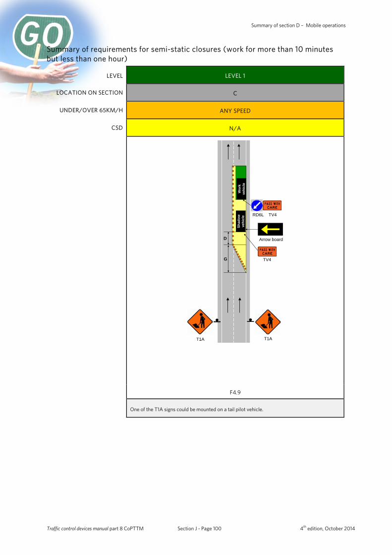
Summary of section D – Mobile operations
Summary of requirements for semi-static closures (work for more than 10 minutes but less than one hour)
LEVEL LEVEL 1
LOCATION ON SECTION C
UNDER/OVER 65KM/H ANY SPEED
CSD N/A
T1A T1A
TV4
TV4RD6L
Arrow boardSh
adow
ve
hicl
eD
Wor
k ve
hicl
e
G
F4.9
One of the T1A signs could be mounted on a tail pilot vehicle.
Traffic control devices manual part 8 CoPTTM Section J - Page 100 4th edition, October 2014
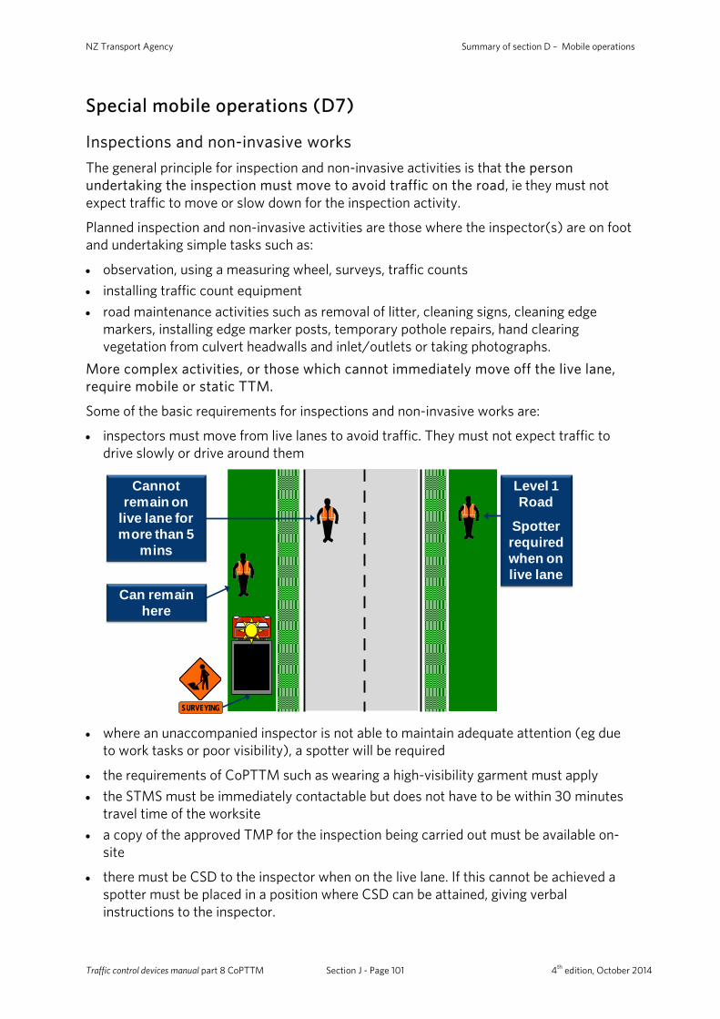
NZ Transport Agency Summary of section D – Mobile operations
Special mobile operations (D7)
Inspections and non-invasive works The general principle for inspection and non-invasive activities is that the person undertaking the inspection must move to avoid traffic on the road, ie they must not expect traffic to move or slow down for the inspection activity.
Planned inspection and non-invasive activities are those where the inspector(s) are on foot and undertaking simple tasks such as:
• observation, using a measuring wheel, surveys, traffic counts • installing traffic count equipment • road maintenance activities such as removal of litter, cleaning signs, cleaning edge
markers, installing edge marker posts, temporary pothole repairs, hand clearing vegetation from culvert headwalls and inlet/outlets or taking photographs.
More complex activities, or those which cannot immediately move off the live lane, require mobile or static TTM.
Some of the basic requirements for inspections and non-invasive works are:
• inspectors must move from live lanes to avoid traffic. They must not expect traffic to drive slowly or drive around them
SURVEYING
Can remain here
Cannot remain on
live lane for more than 5
mins
Level 1 Road
Spotter required when on live lane
• where an unaccompanied inspector is not able to maintain adequate attention (eg due
to work tasks or poor visibility), a spotter will be required
• the requirements of CoPTTM such as wearing a high-visibility garment must apply • the STMS must be immediately contactable but does not have to be within 30 minutes
travel time of the worksite • a copy of the approved TMP for the inspection being carried out must be available on-
site
• there must be CSD to the inspector when on the live lane. If this cannot be achieved a spotter must be placed in a position where CSD can be attained, giving verbal instructions to the inspector.
Traffic control devices manual part 8 CoPTTM Section J - Page 101 4th edition, October 2014
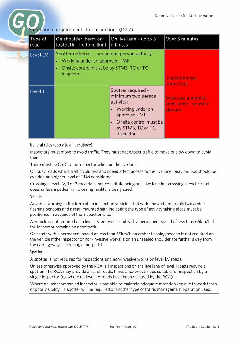
Summary of section D – Mobile operations
Summary of requirements for inspections (D7.7)
Type of road
On shoulder, berm or footpath – no time limit
On live lane – up to 5 minutes
Over 5 minutes
Level LV Spotter optional – can be one person activity: • Working under an approved TMP • Onsite control must be by STMS, TC or TC
Inspector.
Inspection not permitted. Must use a mobile, semi-static, or static closure.
Level 1 Spotter required –minimum two person activity: • Working under an
approved TMP • Onsite control must be
by STMS, TC or TC Inspector.
General rules (apply to all the above)
Inspectors must move to avoid traffic. They must not expect traffic to move or slow down to avoid them. There must be CSD to the inspector when on the live lane. On busy roads where traffic volumes and speed affect access to the live lane, peak periods should be avoided or a higher level of TTM considered. Crossing a level LV, 1 or 2 road does not constitute being on a live lane but crossing a level 3 road does, unless a pedestrian crossing facility is being used.
Vehicle
Advance warning in the form of an inspection vehicle fitted with one and preferably two amber flashing beacons and a rear-mounted sign indicating the type of activity taking place must be positioned in advance of the inspection site. A vehicle is not required on a level LV or level 1 road with a permanent speed of less than 65km/h if the inspector remains on a footpath. On roads with a permanent speed of less than 65km/h an amber flashing beacon is not required on the vehicle if the inspector or non-invasive works is on an unsealed shoulder (or further away from the carriageway - including a footpath).
Spotter
A spotter is not required for inspections and non-invasive works on level LV roads. Unless otherwise approved by the RCA, all inspections on the live lane of level 1 roads require a spotter. The RCA may provide a list of roads, times and/or activities suitable for inspection by a single inspector (eg where no level LV roads have been declared by the RCA). Where an unaccompanied inspector is not able to maintain adequate attention (eg due to work tasks or poor visibility), a spotter will be required or another type of traffic management operation used.
Traffic control devices manual part 8 CoPTTM Section J - Page 102 4th edition, October 2014
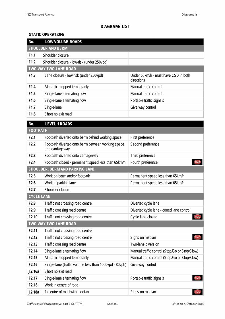
NZ Transport Agency Diagrams list
Traffic control devices manual part 8 CoPTTM Section J 4th edition, October 2014
DIAGRAMS LIST STATIC OPERATIONS
No. LOW VOLUME ROADS SHOULDER AND BERM F1.1 Shoulder closure F1.2 Shoulder closure - low-risk (under 250vpd) TWO-WAY TWO-LANE ROAD F1.3 Lane closure - low-risk (under 250vpd) Under 65km/h - must have CSD in both
directions F1.4 All traffic stopped temporarily Manual traffic control F1.5 Single-lane alternating flow Manual traffic control F1.6 Single-lane alternating flow Portable traffic signals F1.7 Single-lane Give way control F1.8 Short no exit road
No. LEVEL 1 ROADS FOOTPATH F2.1 Footpath diverted onto berm behind working space First preference F2.2 Footpath diverted onto berm between working space
and carriageway Second preference
F2.3 Footpath diverted onto carriageway Third preference F2.4 Footpath closed - permanent speed less than 65km/h Fourth preference SHOULDER, BERM AND PARKING LANE F2.5 Work on berm and/or footpath Permanent speed less than 65km/h F2.6 Work in parking lane Permanent speed less than 65km/h F2.7 Shoulder closure CYCLE LANE F2.8 Traffic not crossing road centre Diverted cycle lane F2.9 Traffic crossing road centre Diverted cycle lane - coned lane control F2.10 Traffic not crossing road centre Cycle lane closed TWO-WAY TWO-LANE ROAD F2.11 Traffic not crossing road centre F2.12 Traffic not crossing road centre Signs on median F2.13 Traffic crossing road centre Two-lane diversion F2.14 Single-lane alternating flow Manual traffic control (Stop/Go or Stop/Slow) F2.15 All traffic stopped temporarily Manual traffic control (Stop/Go or Stop/Slow) F2.16 Single-lane (traffic volume less than 1000vpd - 80vph) Give way control J2.16a Short no exit road F2.17 Single-lane alternating flow Portable traffic signals F2.18 Work in centre of road J2.18a
In centre of road with median Signs on median
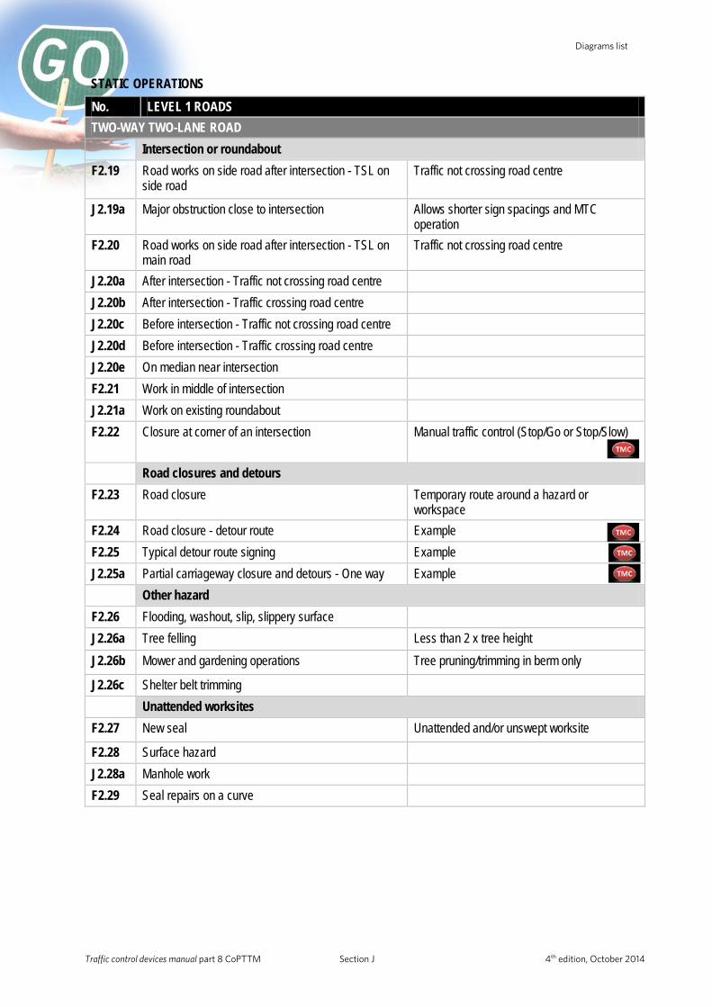
Diagrams list
Traffic control devices manual part 8 CoPTTM Section J 4th edition, October 2014
STATIC OPERATIONS
No. LEVEL 1 ROADS TWO-WAY TWO-LANE ROAD Intersection or roundabout F2.19 Road works on side road after intersection - TSL on
side road Traffic not crossing road centre
J2.19a Major obstruction close to intersection Allows shorter sign spacings and MTC operation
F2.20 Road works on side road after intersection - TSL on main road
Traffic not crossing road centre
J2.20a After intersection - Traffic not crossing road centre J2.20b After intersection - Traffic crossing road centre J2.20c Before intersection - Traffic not crossing road centre J2.20d Before intersection - Traffic crossing road centre J2.20e On median near intersection F2.21 Work in middle of intersection J2.21a Work on existing roundabout F2.22 Closure at corner of an intersection Manual traffic control (Stop/Go or Stop/Slow)
Road closures and detours F2.23 Road closure Temporary route around a hazard or
workspace F2.24 Road closure - detour route Example F2.25 Typical detour route signing Example J2.25a Partial carriageway closure and detours - One way Example Other hazard F2.26 Flooding, washout, slip, slippery surface J2.26a Tree felling Less than 2 x tree height J2.26b Mower and gardening operations Tree pruning/trimming in berm only
J2.26c Shelter belt trimming Unattended worksites F2.27 New seal Unattended and/or unswept worksite
F2.28 Surface hazard J2.28a Manhole work F2.29 Seal repairs on a curve
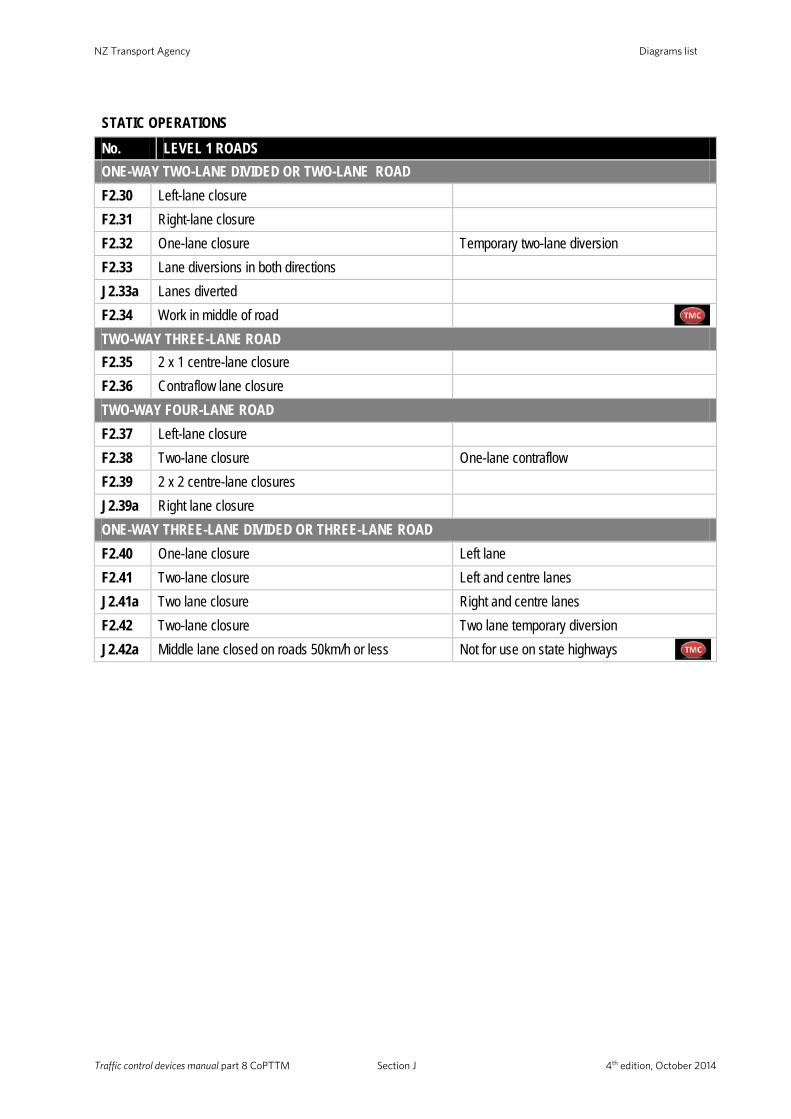
NZ Transport Agency Diagrams list
Traffic control devices manual part 8 CoPTTM Section J 4th edition, October 2014
STATIC OPERATIONS
No. LEVEL 1 ROADS ONE-WAY TWO-LANE DIVIDED OR TWO-LANE ROAD F2.30 Left-lane closure F2.31 Right-lane closure F2.32 One-lane closure Temporary two-lane diversion F2.33 Lane diversions in both directions J2.33a Lanes diverted F2.34 Work in middle of road
TWO-WAY THREE-LANE ROAD F2.35 2 x 1 centre-lane closure F2.36 Contraflow lane closure TWO-WAY FOUR-LANE ROAD F2.37 Left-lane closure F2.38 Two-lane closure One-lane contraflow F2.39 2 x 2 centre-lane closures J2.39a Right lane closure ONE-WAY THREE-LANE DIVIDED OR THREE-LANE ROAD F2.40 One-lane closure Left lane F2.41 Two-lane closure Left and centre lanes J2.41a Two lane closure Right and centre lanes F2.42 Two-lane closure Two lane temporary diversion J2.42a Middle lane closed on roads 50km/h or less Not for use on state highways

Diagrams list
Traffic control devices manual part 8 CoPTTM Section J 4th edition, October 2014
DIAGRAMS LIST MOBILE OPERATIONS
No. LOW-VOLUME ROADS
TWO-WAY TWO-LANE ROAD F3.1 Road inspection activities F3.2 Work vehicle is in a lane With CSD - on LV Low-risk roads (any speed)
and LV roads under 65km/h F3.3 Work vehicle is on berm, shoulder or lane No CSD F3.4 Work vehicle on shoulder or berm - clear of live lane CSD not required No. LEVEL 1 ROADS
TWO-WAY TWO-LANE ROAD F4.1 Work vehicle is more than five (5) metres from the
edgeline Any speed
F4.2 Work vehicle is within five (5) metres of the edgeline CSD to work vehicle: – not required under 65km/h – required over 65km/h
F4.3 Work vehicle is within five (5) metres of the edgeline Speed limit over 65km/h
The rear visibility is less than CSD
F4.4 Work vehicle is in a lane Permanent speed under 65km/h F4.5 Work vehicle is in a lane Permanent speed over 65km/h
CSD forward visibility to work vehicle F4.6 Work vehicle is in a lane Permanent speed over 65km/h
No CSD to work vehicle F4.7 Personnel on the road Any speed ONE-WAY TWO-LANE DIVIDED OR TWO-LANE ROAD F4.8 Work vehicle in the right lane Permanent speed over 65km/h J4.8a Personnel on the road Any speed F4.9 Part or all of a lane occupied Semi-static closure – work for up to 1 hour INSPECTION ACTIVITIES J4.10 On shoulder and on the live lane
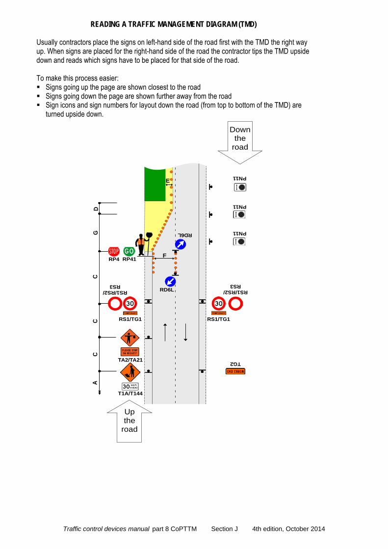
READING A TRAFFIC MANAGEMENT DIAGRAM (TMD)
Usually contractors place the signs on left-hand side of the road first with the TMD the right way up. When signs are placed for the right-hand side of the road the contractor tips the TMD upside down and reads which signs have to be placed for that side of the road. To make this process easier: Signs going up the page are shown closest to the road Signs going down the page are shown further away from the road Sign icons and sign numbers for layout down the road (from top to bottom of the TMD) are
turned upside down.
CC
RS1/RS2/ RS3
RS1/TG1
TG2
RS1/TG1
C
RS1/RS2/ RS3
TA2/TA21
F
DG
T1A/T144
RP41RP4
A
PN11
PN11
PN11RD6L
RD6L
E
Down the
road
Up the
road
Traffic control devices manual part 8 CoPTTM Section J 4th edition, October 2014
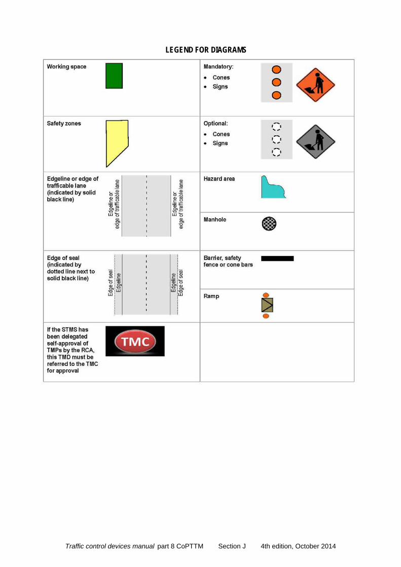
LEGEND FOR DIAGRAMS
Traffic control devices manual part 8 CoPTTM Section J 4th edition, October 2014

LEVEL LV LAYOUT DISTANCES TABLE
Traffic control devices manual part 8 CoPTTM Section J 4th edition, October 2014
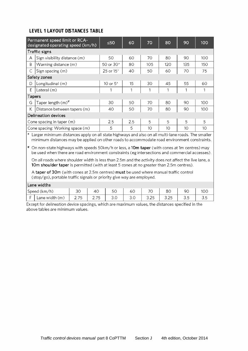
LEVEL 1 LAYOUT DISTANCES TABLE
Traffic control devices manual part 8 CoPTTM Section J 4th edition, October 2014
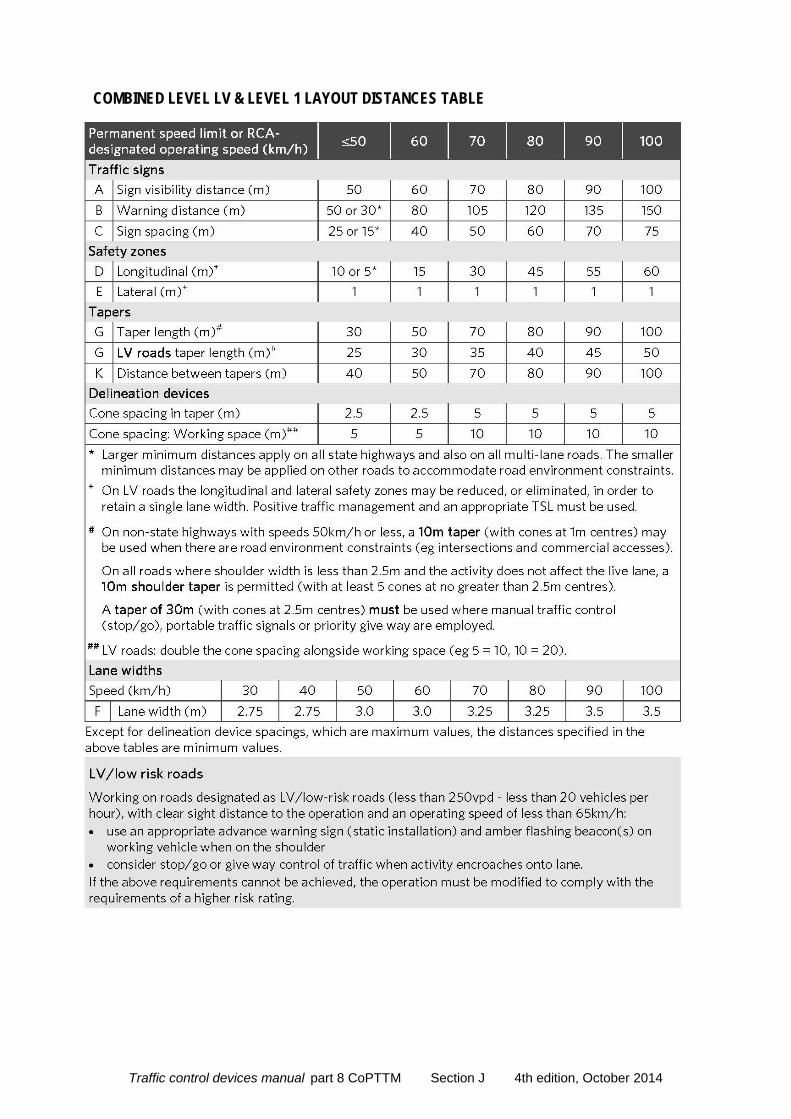
COMBINED LEVEL LV & LEVEL 1 LAYOUT DISTANCES TABLE
Traffic control devices manual part 8 CoPTTM Section J 4th edition, October 2014
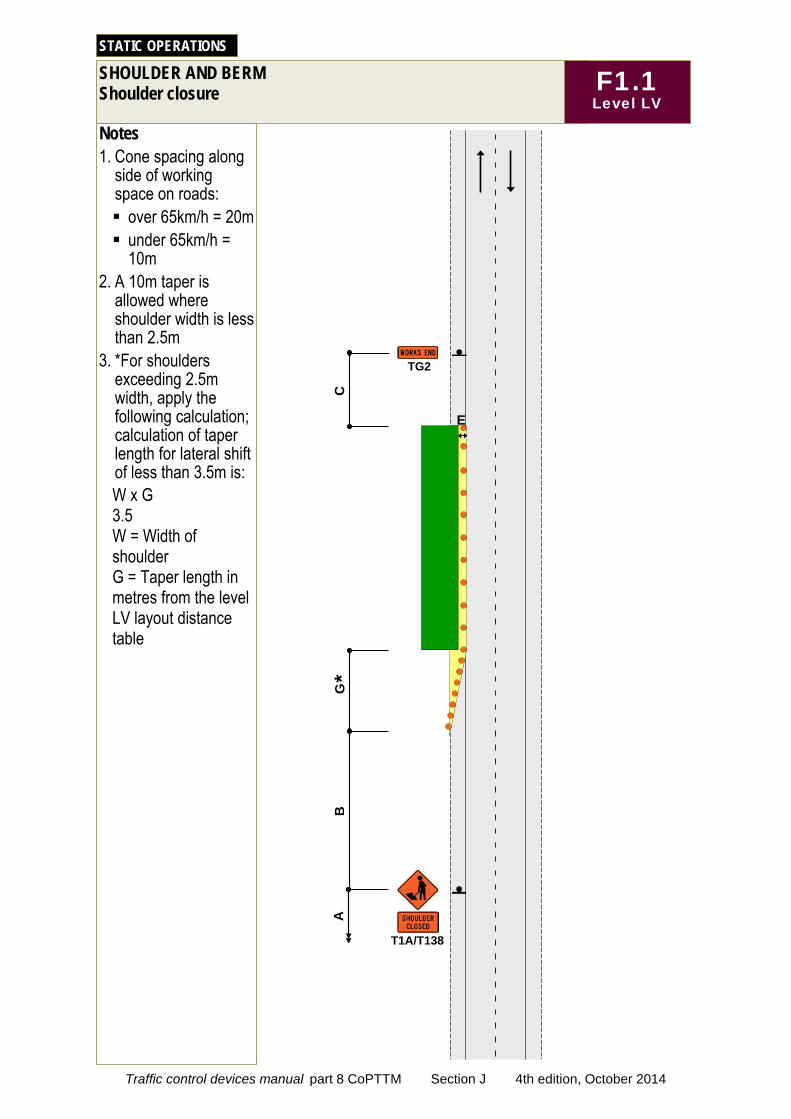
Notes 1. Cone spacing along
side of working space on roads: over 65km/h = 20m under 65km/h =
10m 2. A 10m taper is
allowed where shoulder width is less than 2.5m
3. *For shoulders exceeding 2.5m width, apply the following calculation; calculation of taper length for lateral shift of less than 3.5m is: W x G 3.5 W = Width of shoulder G = Taper length in metres from the level LV layout distance table
SHOULDER AND BERM Shoulder closure
STATIC OPERATIONS
F1.1 Level LV
C
T1A/T138
B
G
TG2
E
A
*
Traffic control devices manual part 8 CoPTTM Section J 4th edition, October 2014

Notes 1. Advance warning
sign may be attached to rear of work vehicle if sign visibility is available
F1.2 Level LV
SHOULDER AND BERM Shoulder closure - low-risk (under 250vpd)
STATIC OPERATIONS
T1A/T138
E
A
Wor
k ve
hicl
e
Low-risk Under 250vpd
B
Traffic control devices manual part 8 CoPTTM Section J 4th edition, October 2014
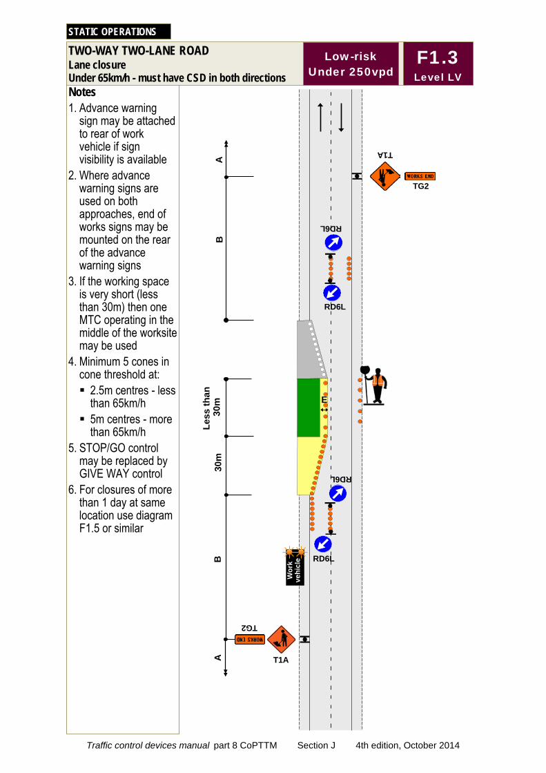
30m
E
Notes 1. Advance warning
sign may be attached to rear of work vehicle if sign visibility is available
2. Where advance warning signs are used on both approaches, end of works signs may be mounted on the rear of the advance warning signs
3. If the working space is very short (less than 30m) then one MTC operating in the middle of the worksite may be used
4. Minimum 5 cones in cone threshold at: 2.5m centres - less
than 65km/h 5m centres - more
than 65km/h 5. STOP/GO control
may be replaced by GIVE WAY control
6. For closures of more than 1 day at same location use diagram F1.5 or similar
TWO-WAY TWO-LANE ROAD Lane closure Under 65km/h - must have CSD in both directions
STATIC OPERATIONS
A
Wor
k ve
hicl
e
Low-risk Under 250vpd
RD6L
RD6L
RD6L
RD6L
Less
than
3
0m
B
B
A
F1.3 Level LV
T1A
TG2
T1A
TG2
Traffic control devices manual part 8 CoPTTM Section J 4th edition, October 2014
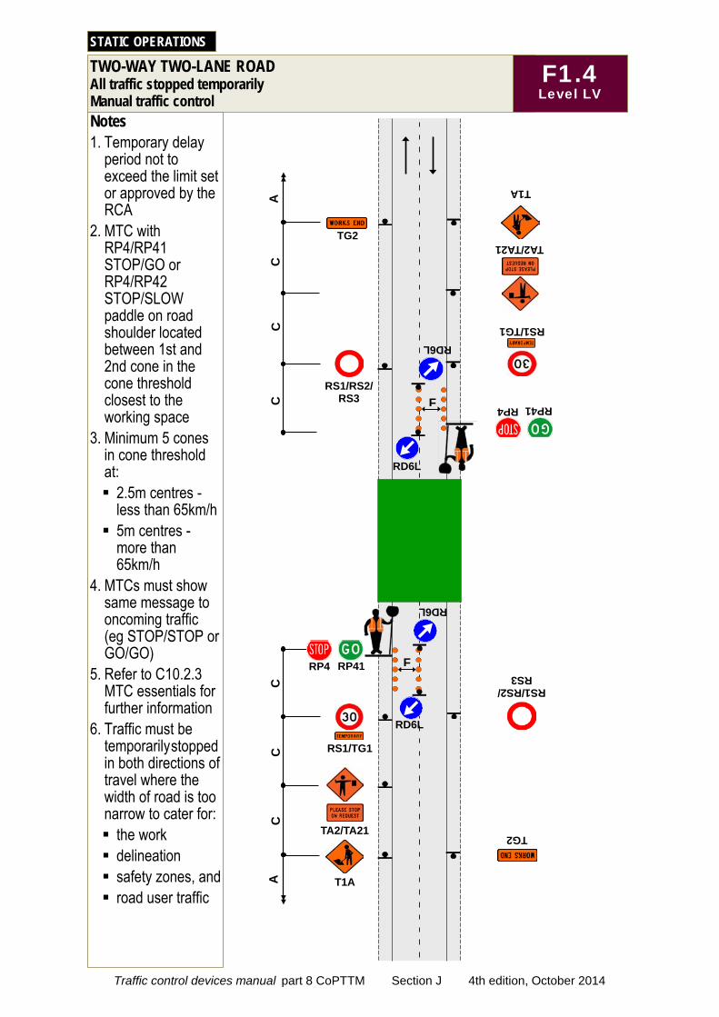
Notes 1. Temporary delay
period not to exceed the limit set or approved by the RCA
2. MTC with RP4/RP41 STOP/GO or RP4/RP42 STOP/SLOW paddle on road shoulder located between 1st and 2nd cone in the cone threshold closest to the working space
3. Minimum 5 cones in cone threshold at: 2.5m centres -
less than 65km/h 5m centres -
more than 65km/h
4. MTCs must show same message to oncoming traffic (eg STOP/STOP or GO/GO)
5. Refer to C10.2.3 MTC essentials for further information
6. Traffic must be temporarily stopped in both directions of travel where the width of road is too narrow to cater for: the work delineation safety zones, and road user traffic
TWO-WAY TWO-LANE ROAD All traffic stopped temporarily Manual traffic control
STATIC OPERATIONS
C
C
TG2
TG2
C
RS1/RS2/ RS3
RS1/RS2/ RS3
RD6L
RD6L
F
F RS1/TG1
TA2/TA21
RP41 RP4
T1A
C
C
RS1/TG1
C
TA2/TA21
T1A
RP41 RP4
A
A
RD6L
RD6L
F1.4 Level LV
Traffic control devices manual part 8 CoPTTM Section J 4th edition, October 2014
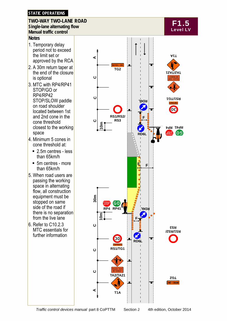
Notes 1. Temporary delay
period not to exceed the limit set or approved by the RCA
2. A 30m return taper at the end of the closure is optional
3. MTC with RP4/RP41 STOP/GO or RP4/RP42 STOP/SLOW paddle on road shoulder located between 1st and 2nd cone in the cone threshold closest to the working space
4. Minimum 5 cones in cone threshold at: 2.5m centres - less
than 65km/h 5m centres - more
than 65km/h 5. When road users are
passing the working space in alternating flow, all construction equipment must be stopped on same side of the road if there is no separation from the live lane
6. Refer to C10.2.3 MTC essentials for further information
TWO-WAY TWO-LANE ROAD Single-lane alternating flow Manual traffic control
STATIC OPERATIONS
RP41 RP4
C
C
C
C
TG2
RS1/TG1
TG2
C
C
RS1/RS2/ RS3
RS1/RS2/ RS3
TA2/TA21
TA2/TA21 RS1/TG1
RP41 RP4
T1A
T1A A
A
30m
F
F 10m
RD6L
RD6L
F
10m
RD6L
RD6L
E
F1.5 Level LV
Traffic control devices manual part 8 CoPTTM Section J 4th edition, October 2014
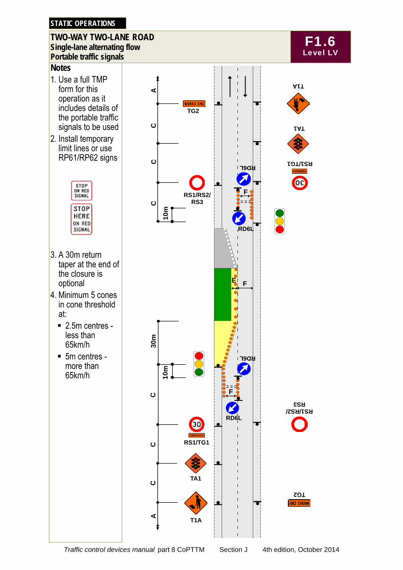
Notes 1. Use a full TMP
form for this operation as it includes details of the portable traffic signals to be used
2. Install temporary limit lines or use RP61/RP62 signs
3. A 30m return taper at the end of the closure is optional
4. Minimum 5 cones in cone threshold at: 2.5m centres -
less than 65km/h 5m centres -
more than 65km/h
TWO-WAY TWO-LANE ROAD Single-lane alternating flow Portable traffic signals
STATIC OPERATIONS
C
C
C
C
RS1/TG1
TG2
RS1/TG1
TG2
C
C
RS1/RS2/ RS3
RS1/RS2/ RS3
TA1
TA1
T1A
T1A
A
A
30m
F
F
F
10m
RD6L
RD6L
RD6L
RD6L
10m
E
F1.6 Level LV
Traffic control devices manual part 8 CoPTTM Section J 4th edition, October 2014
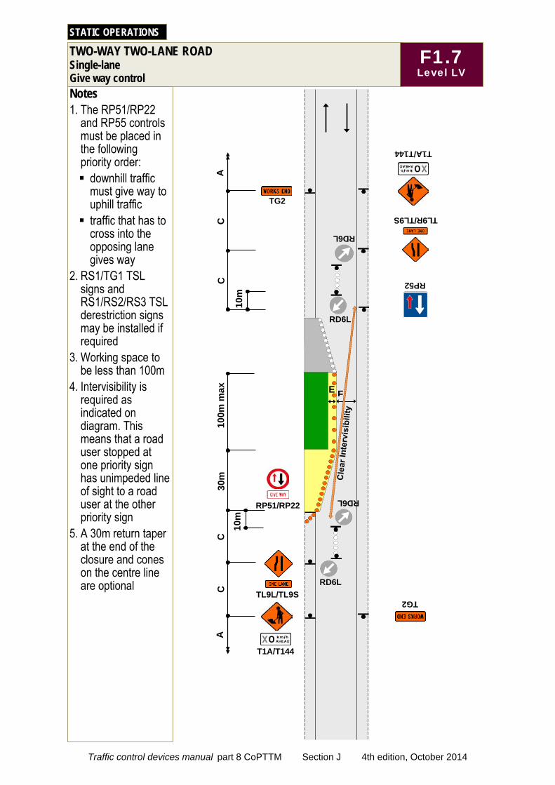
Notes 1. The RP51/RP22
and RP55 controls must be placed in the following priority order: downhill traffic
must give way to uphill traffic traffic that has to
cross into the opposing lane gives way
2. RS1/TG1 TSL signs and RS1/RS2/RS3 TSL derestriction signs may be installed if required
3. Working space to be less than 100m
4. Intervisibility is required as indicated on diagram. This means that a road user stopped at one priority sign has unimpeded line of sight to a road user at the other priority sign
5. A 30m return taper at the end of the closure and cones on the centre line are optional
TWO-WAY TWO-LANE ROAD Single-lane Give way control
STATIC OPERATIONS
F
C
C
C
30m
TG2
C
TG2
TL9R/TL9S
RP51/RP22
TL9L/TL9S
100m
max
T1A/T144
RP52
A
A
T1A/T144
10m
RD6L
RD6L
RD6L
10m
E
RD6L
F1.7 Level LV
Traffic control devices manual part 8 CoPTTM Section J 4th edition, October 2014
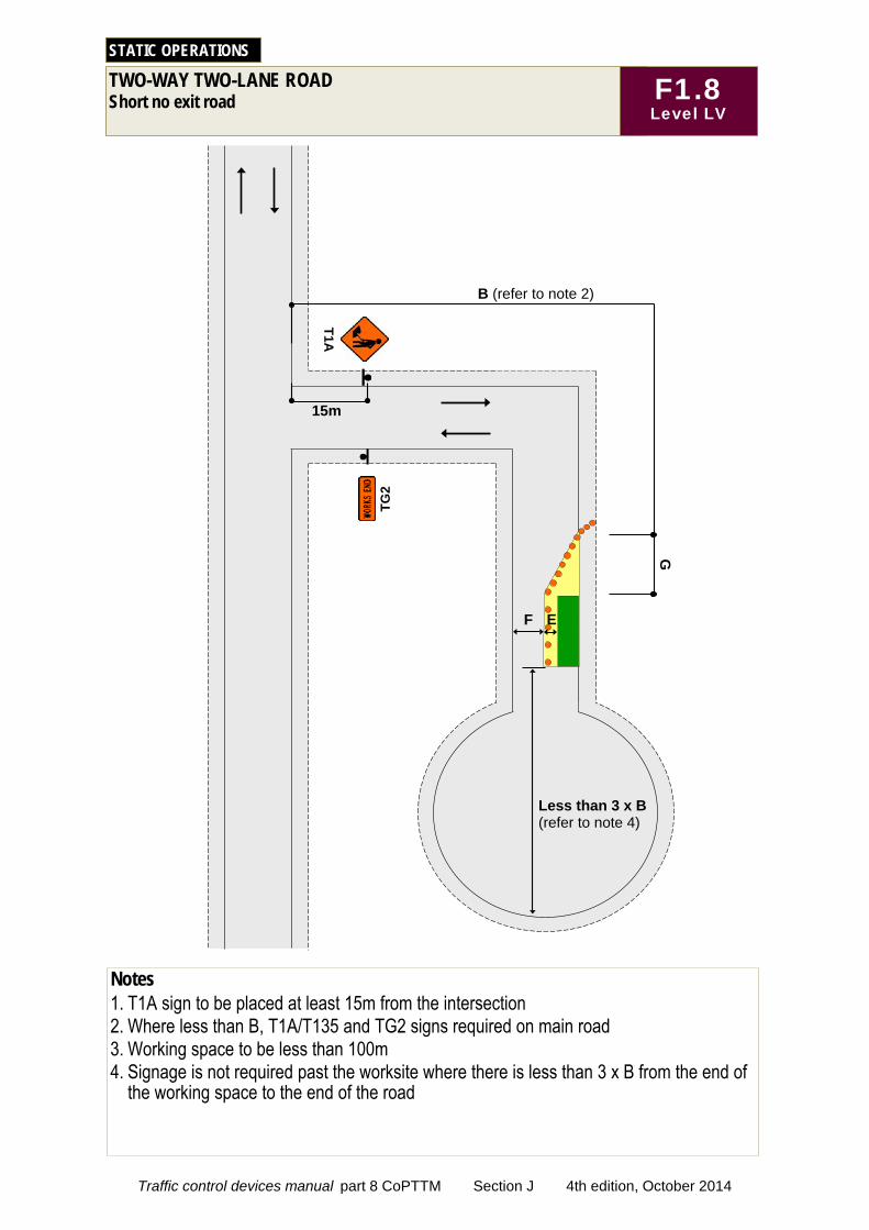
TWO-WAY TWO-LANE ROAD Short no exit road
STATIC OPERATIONS
Notes 1. T1A sign to be placed at least 15m from the intersection 2. Where less than B, T1A/T135 and TG2 signs required on main road 3. Working space to be less than 100m 4. Signage is not required past the worksite where there is less than 3 x B from the end of
the working space to the end of the road
T1A
TG2
E F
G
Less than 3 x B (refer to note 4)
B (refer to note 2)
15m
F1.8 Level LV
Traffic control devices manual part 8 CoPTTM Section J 4th edition, October 2014
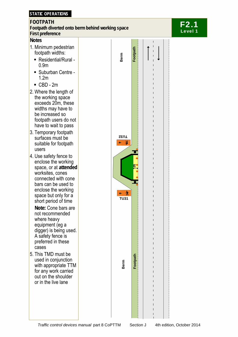
TU32
E
Notes 1. Minimum pedestrian
footpath widths: Residential/Rural -
0.9m Suburban Centre -
1.2m CBD - 2m
2. Where the length of the working space exceeds 20m, these widths may have to be increased so footpath users do not have to wait to pass
3. Temporary footpath surfaces must be suitable for footpath users
4. Use safety fence to enclose the working space, or at attended worksites, cones connected with cone bars can be used to enclose the working space but only for a short period of time Note: Cone bars are not recommended where heavy equipment (eg a digger) is being used. A safety fence is preferred in these cases
5. This TMD must be used in conjunction with appropriate TTM for any work carried out on the shoulder or in the live lane
STATIC OPERATIONS
Foot
path
TU31
Foot
path
Ber
m
Ber
m
FOOTPATH Footpath diverted onto berm behind working space First preference
F2.1 Level 1
Traffic control devices manual part 8 CoPTTM Section J 4th edition, October 2014
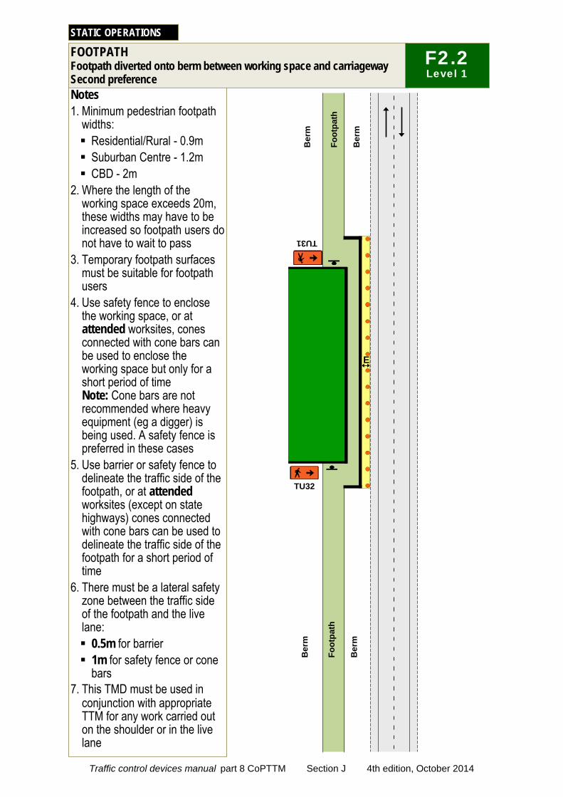
Notes 1. Minimum pedestrian footpath
widths: Residential/Rural - 0.9m Suburban Centre - 1.2m CBD - 2m
2. Where the length of the working space exceeds 20m, these widths may have to be increased so footpath users do not have to wait to pass
3. Temporary footpath surfaces must be suitable for footpath users
4. Use safety fence to enclose the working space, or at attended worksites, cones connected with cone bars can be used to enclose the working space but only for a short period of time Note: Cone bars are not recommended where heavy equipment (eg a digger) is being used. A safety fence is preferred in these cases
5. Use barrier or safety fence to delineate the traffic side of the footpath, or at attended worksites (except on state highways) cones connected with cone bars can be used to delineate the traffic side of the footpath for a short period of time
6. There must be a lateral safety zone between the traffic side of the footpath and the live lane: 0.5m for barrier 1m for safety fence or cone
bars 7. This TMD must be used in
conjunction with appropriate TTM for any work carried out on the shoulder or in the live lane
STATIC OPERATIONS
Foot
path
Ber
m
Ber
m
TU32
TU31
E
Foot
path
Ber
m
Ber
m
FOOTPATH Footpath diverted onto berm between working space and carriageway Second preference
F2.2 Level 1
Traffic control devices manual part 8 CoPTTM Section J 4th edition, October 2014
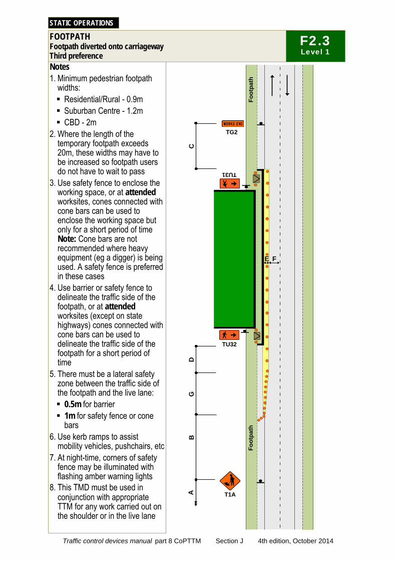
Notes 1. Minimum pedestrian footpath
widths: Residential/Rural - 0.9m Suburban Centre - 1.2m CBD - 2m
2. Where the length of the temporary footpath exceeds 20m, these widths may have to be increased so footpath users do not have to wait to pass
3. Use safety fence to enclose the working space, or at attended worksites, cones connected with cone bars can be used to enclose the working space but only for a short period of time Note: Cone bars are not recommended where heavy equipment (eg a digger) is being used. A safety fence is preferred in these cases
4. Use barrier or safety fence to delineate the traffic side of the footpath, or at attended worksites (except on state highways) cones connected with cone bars can be used to delineate the traffic side of the footpath for a short period of time
5. There must be a lateral safety zone between the traffic side of the footpath and the live lane: 0.5m for barrier 1m for safety fence or cone
bars 6. Use kerb ramps to assist
mobility vehicles, pushchairs, etc 7. At night-time, corners of safety
fence may be illuminated with flashing amber warning lights
8. This TMD must be used in conjunction with appropriate TTM for any work carried out on the shoulder or in the live lane
STATIC OPERATIONS
Foot
path
TU32
TU31
A
B
T1A
TG2
C
TG2
D
G
F E Fo
otpa
th
FOOTPATH Footpath diverted onto carriageway Third preference
F2.3 Level 1
Traffic control devices manual part 8 CoPTTM Section J 4th edition, October 2014
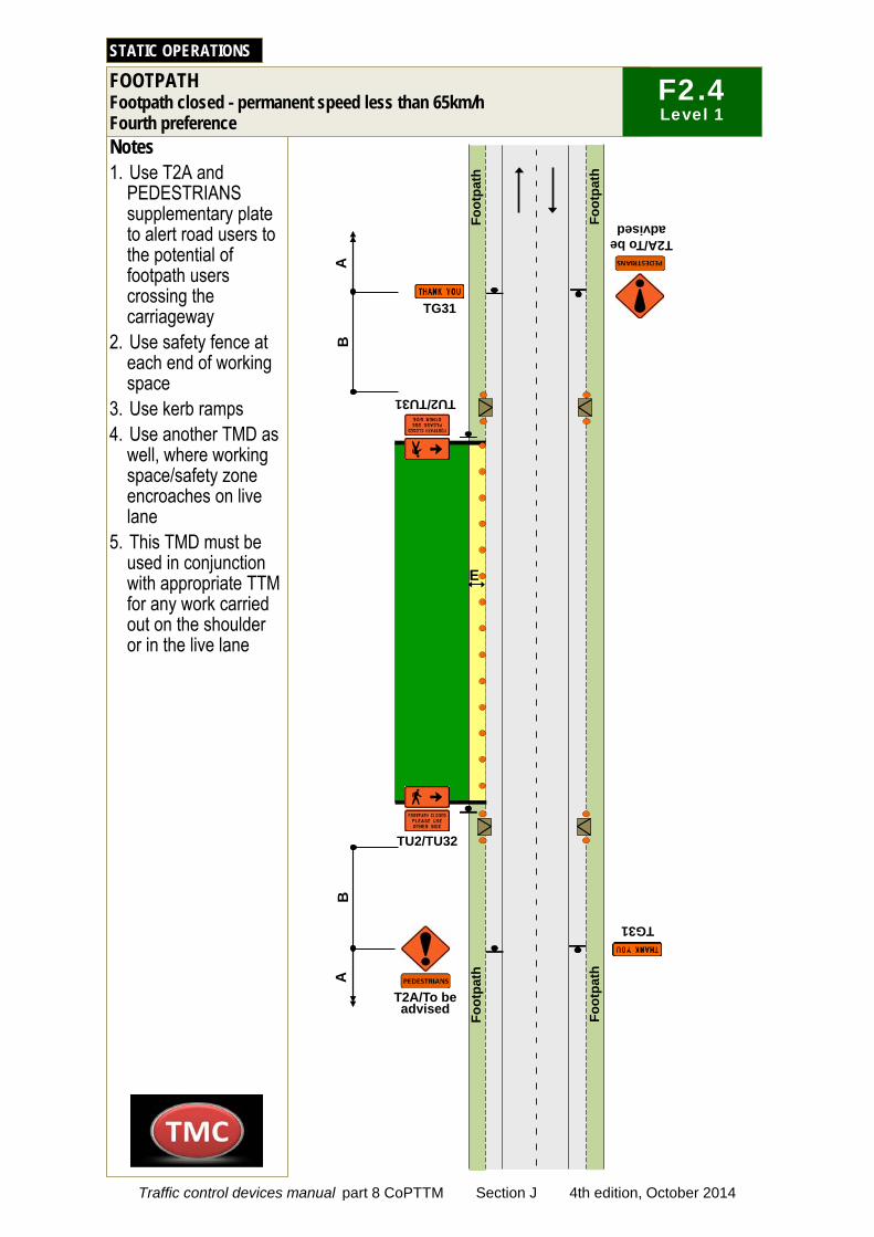
Notes 1. Use T2A and
PEDESTRIANS supplementary plate to alert road users to the potential of footpath users crossing the carriageway
2. Use safety fence at each end of working space
3. Use kerb ramps 4. Use another TMD as
well, where working space/safety zone encroaches on live lane
5. This TMD must be used in conjunction with appropriate TTM for any work carried out on the shoulder or in the live lane
Foot
path
E
STATIC OPERATIONS
Foot
path
TU2/TU32
A
A
T2A/To be advised
B
TU2/TU31
B
Foot
path
Foot
path
T2A/To be advised
TG31 TG31
FOOTPATH Footpath closed - permanent speed less than 65km/h Fourth preference
F2.4 Level 1
Traffic control devices manual part 8 CoPTTM Section J 4th edition, October 2014
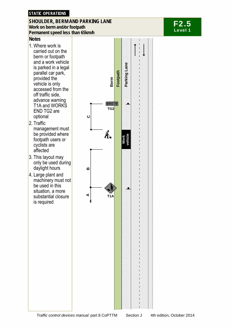
Notes 1. Where work is
carried out on the berm or footpath and a work vehicle is parked in a legal parallel car park, provided the vehicle is only accessed from the off traffic side, advance warning T1A and WORKS END TG2 are optional
2. Traffic management must be provided where footpath users or cyclists are affected
3. This layout may only be used during daylight hours
4. Large plant and machinery must not be used in this situation, a more substantial closure is required
STATIC OPERATIONS
Ber
m
Park
ing
Lane
Foot
path
W
ork
vehi
cle
A
B
T1A
TG2
C
TG2
SHOULDER, BERM AND PARKING LANE Work on berm and/or footpath Permanent speed less than 65km/h
F2.5 Level 1
Traffic control devices manual part 8 CoPTTM Section J 4th edition, October 2014
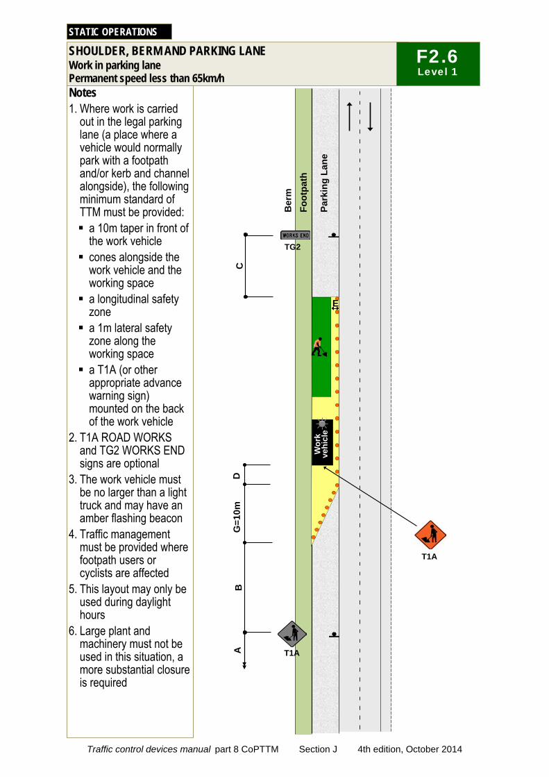
Ber
m
Park
ing
Lane
Foot
path
Notes 1. Where work is carried
out in the legal parking lane (a place where a vehicle would normally park with a footpath and/or kerb and channel alongside), the following minimum standard of TTM must be provided: a 10m taper in front of
the work vehicle cones alongside the
work vehicle and the working space a longitudinal safety
zone a 1m lateral safety
zone along the working space a T1A (or other
appropriate advance warning sign) mounted on the back of the work vehicle
2. T1A ROAD WORKS and TG2 WORKS END signs are optional
3. The work vehicle must be no larger than a light truck and may have an amber flashing beacon
4. Traffic management must be provided where footpath users or cyclists are affected
5. This layout may only be used during daylight hours
6. Large plant and machinery must not be used in this situation, a more substantial closure is required
STATIC OPERATIONS
E
G=1
0m
D
T1A
Wor
k ve
hicl
e
A
B
T1A
TG2 C
TG2
SHOULDER, BERM AND PARKING LANE Work in parking lane Permanent speed less than 65km/h
F2.6 Level 1
Traffic control devices manual part 8 CoPTTM Section J 4th edition, October 2014

C
T1A/T138
Notes 1. A 10m taper is
allowed where shoulder width is less than 2.5m
2. *For shoulders exceeding 2.5m width, apply the following calculation; calculation of taper length for lateral shift of less than 3.5m is: W x G 3.5 W = Width of shoulder G = Taper length in metres from the level 1 layout distance table
STATIC OPERATIONS
B
D
G
TG2
E
A
*
SHOULDER, BERM AND PARKING LANE Shoulder closure
F2.7 Level 1
Traffic control devices manual part 8 CoPTTM Section J 4th edition, October 2014
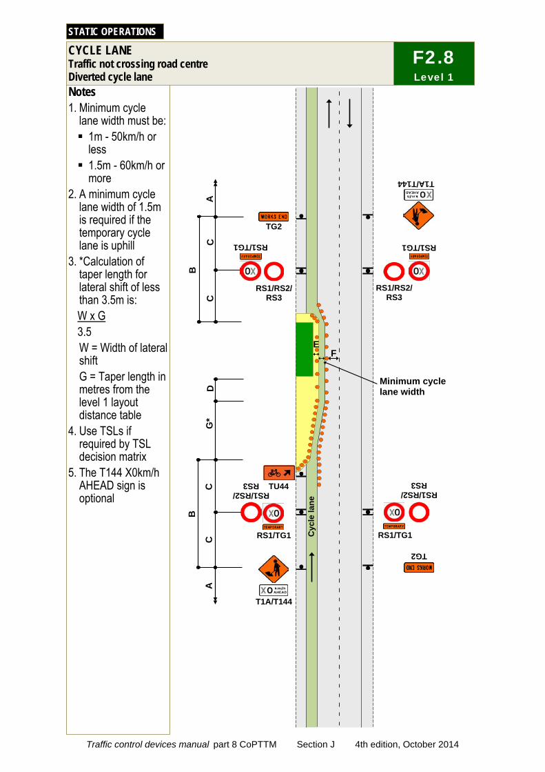
C
C
C
Notes 1. Minimum cycle
lane width must be: 1m - 50km/h or
less 1.5m - 60km/h or
more 2. A minimum cycle
lane width of 1.5m is required if the temporary cycle lane is uphill
3. *Calculation of taper length for lateral shift of less than 3.5m is: W x G 3.5 W = Width of lateral shift G = Taper length in metres from the level 1 layout distance table
4. Use TSLs if required by TSL decision matrix
5. The T144 X0km/h AHEAD sign is optional
STATIC OPERATIONS
C
D
G*
B
B
TG2
TG2
T1A/T144
RS1/RS2/ RS3
RS1/RS2/ RS3
RS1/RS2/ RS3
RS1/RS2/ RS3
RS1/TG1
RS1/TG1 RS1/TG1
RS1/TG1
A
A
Cyc
le la
ne
T1A/T144
Minimum cycle lane width
F E
TU44
CYCLE LANE Traffic not crossing road centre Diverted cycle lane
F2.8 Level 1
Traffic control devices manual part 8 CoPTTM Section J 4th edition, October 2014
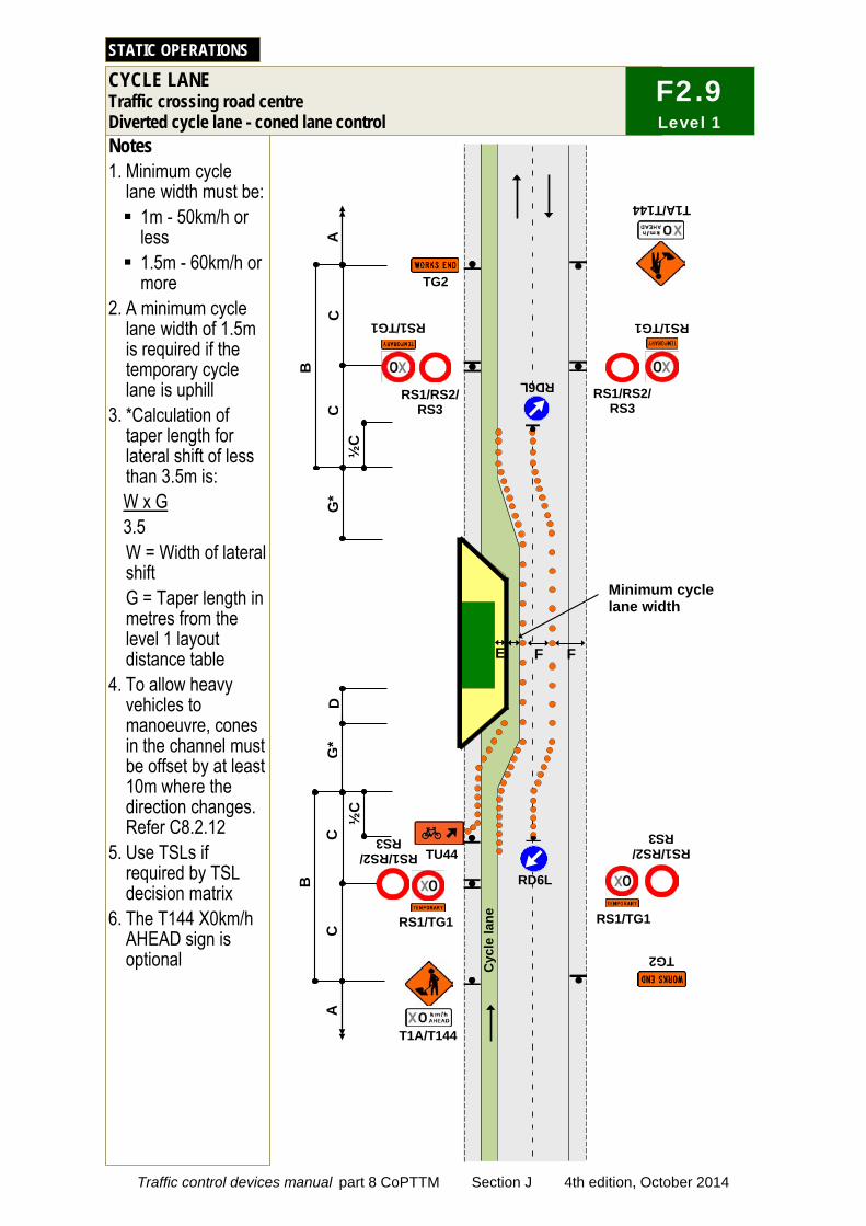
Notes 1. Minimum cycle
lane width must be: 1m - 50km/h or
less 1.5m - 60km/h or
more 2. A minimum cycle
lane width of 1.5m is required if the temporary cycle lane is uphill
3. *Calculation of taper length for lateral shift of less than 3.5m is: W x G 3.5 W = Width of lateral shift G = Taper length in metres from the level 1 layout distance table
4. To allow heavy vehicles to manoeuvre, cones in the channel must be offset by at least 10m where the direction changes. Refer C8.2.12
5. Use TSLs if required by TSL decision matrix
6. The T144 X0km/h AHEAD sign is optional
STATIC OPERATIONS
Minimum cycle lane width
G*
F F
Cyc
le la
ne
TG2
RS1/RS2/ RS3
RS1/TG1
RS1/RS2/ RS3
RS1/TG1
T1A/T144
B
C
C
TG2
RS1/RS2/ RS3
RS1/TG1
A
C
C
D
G*
B
T1A/T144
RS1/RS2/ RS3
RS1/TG1
A
E
½C
RD6L
½C
RD6L TU44
CYCLE LANE Traffic crossing road centre Diverted cycle lane - coned lane control
F2.9 Level 1
Traffic control devices manual part 8 CoPTTM Section J 4th edition, October 2014
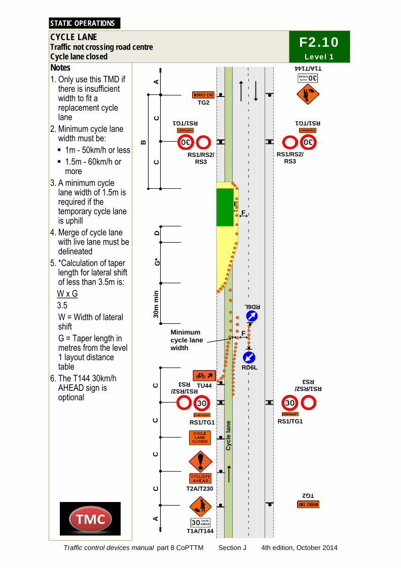
Notes 1. Only use this TMD if
there is insufficient width to fit a replacement cycle lane
2. Minimum cycle lane width must be: 1m - 50km/h or less 1.5m - 60km/h or
more 3. A minimum cycle
lane width of 1.5m is required if the temporary cycle lane is uphill
4. Merge of cycle lane with live lane must be delineated
5. *Calculation of taper length for lateral shift of less than 3.5m is: W x G 3.5 W = Width of lateral shift G = Taper length in metres from the level 1 layout distance table
6. The T144 30km/h AHEAD sign is optional
STATIC OPERATIONS
Cyc
le la
ne
TG2
RS1/RS2/ RS3
RS1/RS2/ RS3
T1A/T144
B
C
C
TG2
RS1/RS2/ RS3
A
C
30m
min
T1A/T144
RS1/RS2/ RS3
A
RD6L
TU44
T2A/T230
RD6L
D
G*
F Minimum cycle lane width
RS1/TG1 RS1/TG1
RS1/TG1 RS1/TG1 CYCLE LANE
CLOSED
C
C
C
CYCLE LANE Traffic not crossing road centre Cycle lane closed
F2.10 Level 1
F E
Traffic control devices manual part 8 CoPTTM Section J 4th edition, October 2014
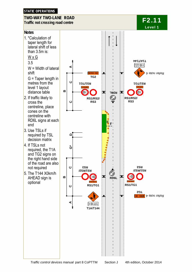
C
C
C
Notes 1. *Calculation of
taper length for lateral shift of less than 3.5m is: W x G 3.5 W = Width of lateral shift G = Taper length in metres from the level 1 layout distance table
2. If traffic likely to cross the centreline, place cones on the centreline with RD6L signs at each end
3. Use TSLs if required by TSL decision matrix
4. If TSLs not required, the T1A and TG2 signs on the right hand side of the road are also not required
5. The T144 X0km/h AHEAD sign is optional
STATIC OPERATIONS
C
B
B
TG2 TG2
T1A/T144
RS1/RS2/ RS3
RS1/RS2/ RS3
RS1/RS2/ RS3
RS1/RS2/
RS3
RS1/TG1 RS1/TG1
RS1/TG1 RS1/TG1
A
A
T1A/T144
D
F E
G*
RD6L RD6L
Refer note 4
Refer note 4
TWO-WAY TWO-LANE ROAD Traffic not crossing road centre
F2.11 Level 1
Traffic control devices manual part 8 CoPTTM Section J 4th edition, October 2014
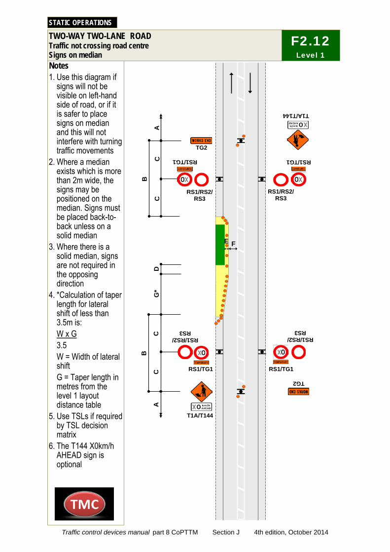
D
C
C
C
Notes 1. Use this diagram if
signs will not be visible on left-hand side of road, or if it is safer to place signs on median and this will not interfere with turning traffic movements
2. Where a median exists which is more than 2m wide, the signs may be positioned on the median. Signs must be placed back-to-back unless on a solid median
3. Where there is a solid median, signs are not required in the opposing direction
4. *Calculation of taper length for lateral shift of less than 3.5m is: W x G 3.5 W = Width of lateral shift G = Taper length in metres from the level 1 layout distance table
5. Use TSLs if required by TSL decision matrix
6. The T144 X0km/h AHEAD sign is optional
STATIC OPERATIONS
C
G*
B
B
TG2
TG2
T1A/T144
RS1/RS2/ RS3
RS1/RS2/ RS3
RS1/RS2/ RS3
RS1/RS2/
RS3
RS1/TG1
RS1/TG1
RS1/TG1
RS1/TG1
A
A
T1A/T144
F E
TWO-WAY TWO-LANE ROAD Traffic not crossing road centre Signs on median
F2.12 Level 1
Traffic control devices manual part 8 CoPTTM Section J 4th edition, October 2014
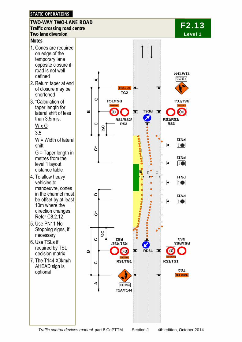
C
C
C
Notes 1. Cones are required
on edge of the temporary lane opposite closure if road is not well defined
2. Return taper at end of closure may be shortened
3. *Calculation of taper length for lateral shift of less than 3.5m is: W x G 3.5 W = Width of lateral shift G = Taper length in metres from the level 1 layout distance table
4. To allow heavy vehicles to manoeuvre, cones in the channel must be offset by at least 10m where the direction changes. Refer C8.2.12
5. Use PN11 No Stopping signs, if necessary
6. Use TSLs if required by TSL decision matrix
7. The T144 X0km/h AHEAD sign is optional
TWO-WAY TWO-LANE ROAD Traffic crossing road centre Two lane diversion
STATIC OPERATIONS
C
D
G*
RD6L
F F
B
B
TG2
TG2
T1A/T144
T1A/T144
RS1/RS2/ RS3
RS1/RS2/ RS3
RS1/RS2/ RS3
RS1/RS2/ RS3
RS1/TG1
RS1/TG1
RS1/TG1
RS1/TG1
PN11
PN11
PN11
PN11
A
A
E
G*
RD6L
½C
½
C
F2.13 Level 1
Traffic control devices manual part 8 CoPTTM Section J 4th edition, October 2014

Notes 1. Extend or place extra
advance warning signs towards on-coming traffic beyond any expected traffic queues
2. A 30m return taper at the end of the closure is mandatory
3. Cones are required on edge of the temporary lane opposite closure if road is not well defined
4. To allow heavy vehicles to manoeuvre, cones in the channel must be offset by at least 10m where the direction changes. Refer C8.2.12
5. Use PN11 no stopping signs, if necessary
6. MTC with RP4/RP41 STOP/GO or RP4/RP42 STOP/SLOW paddle on road shoulder located between 1st and 2nd cone in the cone threshold closest to the working space
7. Minimum 5 cones in cone threshold at: 2.5m centres - less
than 65km/h 5m centres - more
than 65km/h 8. Refer to C10.2.3 MTC
essentials for further information
9. Delays cannot exceed the time approved by the RCA (normally 5 to 10 minutes)
10.The T144 30km/h AHEAD sign is optional
TWO-WAY TWO-LANE ROAD Single-lane alternating flow Manual traffic control (STOP/GO or STOP/SLOW)
STATIC OPERATIONS
TG2
C
TA2/TA21
RS1/TG1
T1A/T144
A
RP41 RP4
C
C
C
C
RS1/RS2/ RS3
RS1/TG1
TG2
RS1/TG1
RS1/RS2/ RS3
RS1/TG1 C
RS1/RS2/ RS3
RS1/RS2/ RS3
TA2/TA21
T1A/T144
RP41 RP4
A
F
PN11
PN11
PN11
PN11
D
F
30m
30
m
E
RD6L
RD6L
10m
F
10m
RD6L
RD6L
F2.14 Level 1
Traffic control devices manual part 8 CoPTTM Section J 4th edition, October 2014
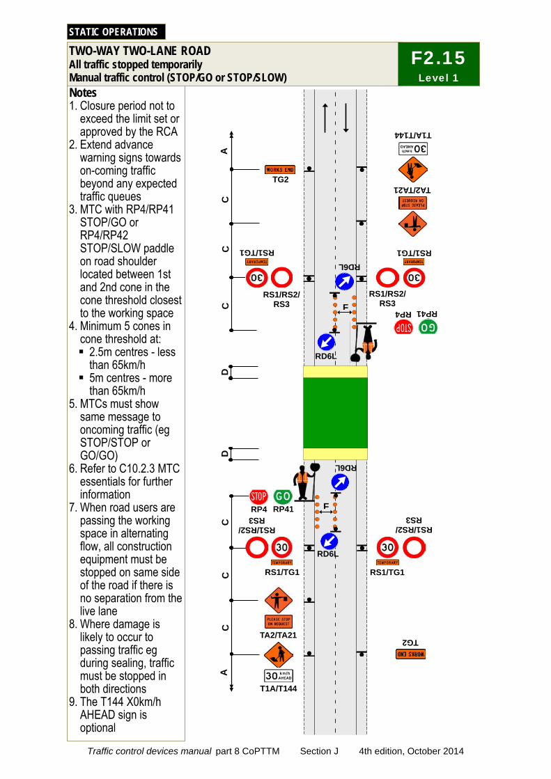
C
C
TG2
TG2
RS1/TG1
RS1/TG1
Notes 1. Closure period not to
exceed the limit set or approved by the RCA
2. Extend advance warning signs towards on-coming traffic beyond any expected traffic queues
3. MTC with RP4/RP41 STOP/GO or RP4/RP42 STOP/SLOW paddle on road shoulder located between 1st and 2nd cone in the cone threshold closest to the working space
4. Minimum 5 cones in cone threshold at: 2.5m centres - less
than 65km/h 5m centres - more
than 65km/h 5. MTCs must show
same message to oncoming traffic (eg STOP/STOP or GO/GO)
6. Refer to C10.2.3 MTC essentials for further information
7. When road users are passing the working space in alternating flow, all construction equipment must be stopped on same side of the road if there is no separation from the live lane
8. Where damage is likely to occur to passing traffic eg during sealing, traffic must be stopped in both directions
9. The T144 X0km/h AHEAD sign is optional
TWO-WAY TWO-LANE ROAD All traffic stopped temporarily Manual traffic control (STOP/GO or STOP/SLOW)
STATIC OPERATIONS
C
RS1/RS2/ RS3
RS1/RS2/ RS3
RD6L
RD6L
F
F RS1/TG1
RS1/RS2/ RS3
TA2/TA21
RP41 RP4
T1A/T144
C
C
RS1/RS2/ RS3
RS1/TG1
C
TA2/TA21
T1A/T144
RP41 RP4
A
A
RD6L
RD6L
D
D
F2.15 Level 1
Traffic control devices manual part 8 CoPTTM Section J 4th edition, October 2014
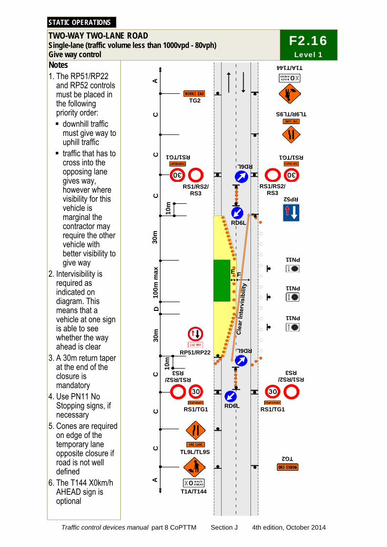
30m
F
D
C
C
C
C
30m
RS1/TG1
TG2
RS1/TG1
RS1/TG1
RS1/RS2/ RS3
Notes 1. The RP51/RP22
and RP52 controls must be placed in the following priority order: downhill traffic
must give way to uphill traffic traffic that has to
cross into the opposing lane gives way, however where visibility for this vehicle is marginal the contractor may require the other vehicle with better visibility to give way
2. Intervisibility is required as indicated on diagram. This means that a vehicle at one sign is able to see whether the way ahead is clear
3. A 30m return taper at the end of the closure is mandatory
4. Use PN11 No Stopping signs, if necessary
5. Cones are required on edge of the temporary lane opposite closure if road is not well defined
6. The T144 X0km/h AHEAD sign is optional
TWO-WAY TWO-LANE ROAD Single-lane (traffic volume less than 1000vpd - 80vph) Give way control
STATIC OPERATIONS
C
RS1/RS2/ RS3
TG2
RS1/TG1
RS1/RS2/ RS3
RS1/RS2/ RS3
TL9R/TL9S
RP51/RP22
TL9L/TL9S
100m
max
T1A/T144
RP52
PN11
PN11
PN11
A
A
T1A/T144
C
E
10m
RD6L
RD6L
RD6L
RD6L
10m
F2.16 Level 1
Traffic control devices manual part 8 CoPTTM Section J 4th edition, October 2014

TWO-WAY TWO-LANE ROAD Short no exit road
STATIC OPERATIONS
Notes 1. T1A sign to be placed at least 15m from the intersection 2. Where less than B, T1A/T135 and TG2 signs required on main road 3. Working space to be less than 100m 4. Signage is not required past the worksite where there is less than 3 x B from the end of
the working space to the end of the road
T1A
TG2
E F
G
Less than 3 x B (refer to note 4)
B (refer to note 2)
15m
J2.16a Level 1
Traffic control devices manual part 8 CoPTTM Section J 4th edition, October 2014
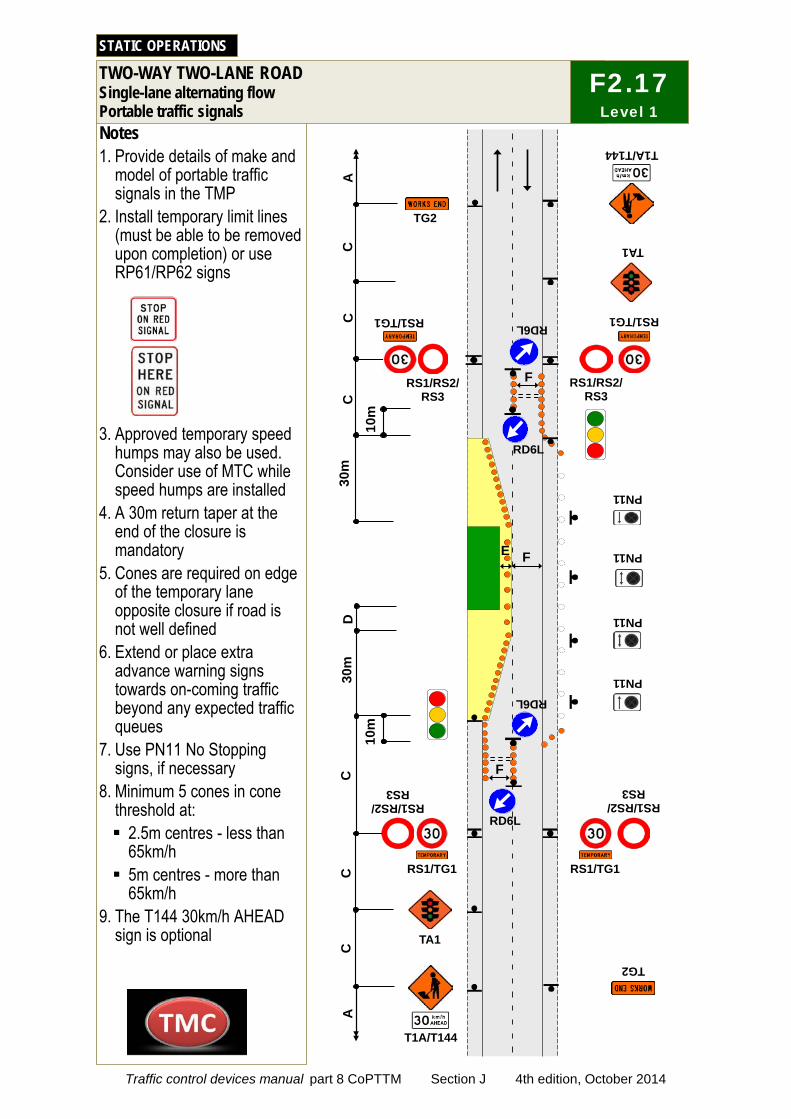
C
C
C
C
RS1/RS2/ RS3
RS1/TG1
TG2
RS1/TG1
TG2
RS1/TG1
RS1/RS2/ RS3
RS1/TG1
Notes 1. Provide details of make and
model of portable traffic signals in the TMP
2. Install temporary limit lines (must be able to be removed upon completion) or use RP61/RP62 signs
3. Approved temporary speed humps may also be used. Consider use of MTC while speed humps are installed
4. A 30m return taper at the end of the closure is mandatory
5. Cones are required on edge of the temporary lane opposite closure if road is not well defined
6. Extend or place extra advance warning signs towards on-coming traffic beyond any expected traffic queues
7. Use PN11 No Stopping signs, if necessary
8. Minimum 5 cones in cone threshold at: 2.5m centres - less than
65km/h 5m centres - more than
65km/h 9. The T144 30km/h AHEAD
sign is optional
TWO-WAY TWO-LANE ROAD Single-lane alternating flow Portable traffic signals
STATIC OPERATIONS
C
C
RS1/RS2/ RS3
RS1/RS2/ RS3
TA1
TA1
T1A/T144
T1A/T144
A
A
D
30m
3
0m
PN11
PN11
PN11
PN11
E F
F
F 10
m
RD6L
RD6L
RD6L
RD6L
10m
F2.17 Level 1
Traffic control devices manual part 8 CoPTTM Section J 4th edition, October 2014
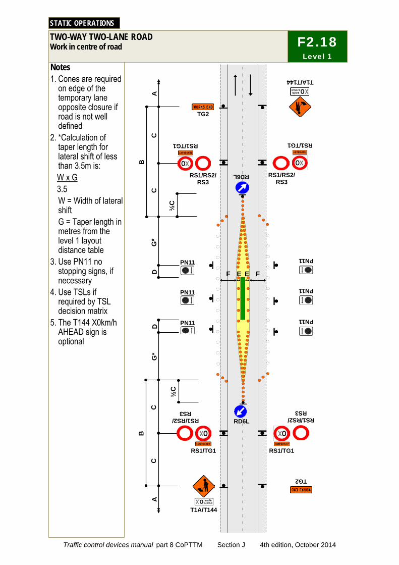
Notes 1. Cones are required
on edge of the temporary lane opposite closure if road is not well defined
2. *Calculation of taper length for lateral shift of less than 3.5m is: W x G 3.5 W = Width of lateral shift G = Taper length in metres from the level 1 layout distance table
3. Use PN11 no stopping signs, if necessary
4. Use TSLs if required by TSL decision matrix
5. The T144 X0km/h AHEAD sign is optional
TWO-WAY TWO-LANE ROAD Work in centre of road
STATIC OPERATIONS
C
C
RS1/RS2/ RS3
D
B
D
PN11
PN11
PN11
PN11
PN11
PN11
RD6L
RS1/TG1
T1A/T144
TG2
RS1/RS2/ RS3
RS1/TG1
A
F E
½C
G*
G*
F E
C
TG2
C
B
RD6L RS1/RS2/ RS3
RS1/RS2/ RS3
RS1/TG1 RS1/TG1
T1A/T144
A
½C
F2.18 Level 1
Traffic control devices manual part 8 CoPTTM Section J 4th edition, October 2014

Notes 1. Use this diagram if
signs will not be visible on left-hand side of road, or if it is safer to place signs on median and this will not interfere with turning traffic movements
2. Where a median exists which is more than 1.5m wide, the signs may be positioned on the median. Signs must be placed back-to-back unless on a solid median
3. Where there is a solid median, signs are not required in the opposing direction
4. Cones are required on edge of the temporary lane opposite closure if road is not well defined
5. *Calculation of taper length for lateral shift of less than 3.5m is: W x G 3.5 W = Width of lane G = Taper length in metres from the level 1 layout distance table
6. Use PN11 No Stopping signs, if necessary
7. Use TSLs if required by TSL decision matrix
8. The T144 X0km/h AHEAD sign is optional
TWO-WAY TWO-LANE ROAD In centre of road with median, signs on median
STATIC OPERATIONS
C
C
C
RS1/RS2/ RS3
TG2
C
D
B
B
D
PN11
PN11
PN11
PN11
PN11
PN11
RD6L
RS1/TG1
T1A/T144
TG2
RS1/RS2/ RS3
RS1/TG1
RS1/RS2/ RS3
RS1/RS2/ RS3
RS1/TG1 RS1/TG1
T1A/T144
A
A
F E
G*
G*
E
RD6L
RD6L
½C
RD6L
½C
F
J2.18a Level 1
Traffic control devices manual part 8 CoPTTM Section J 4th edition, October 2014
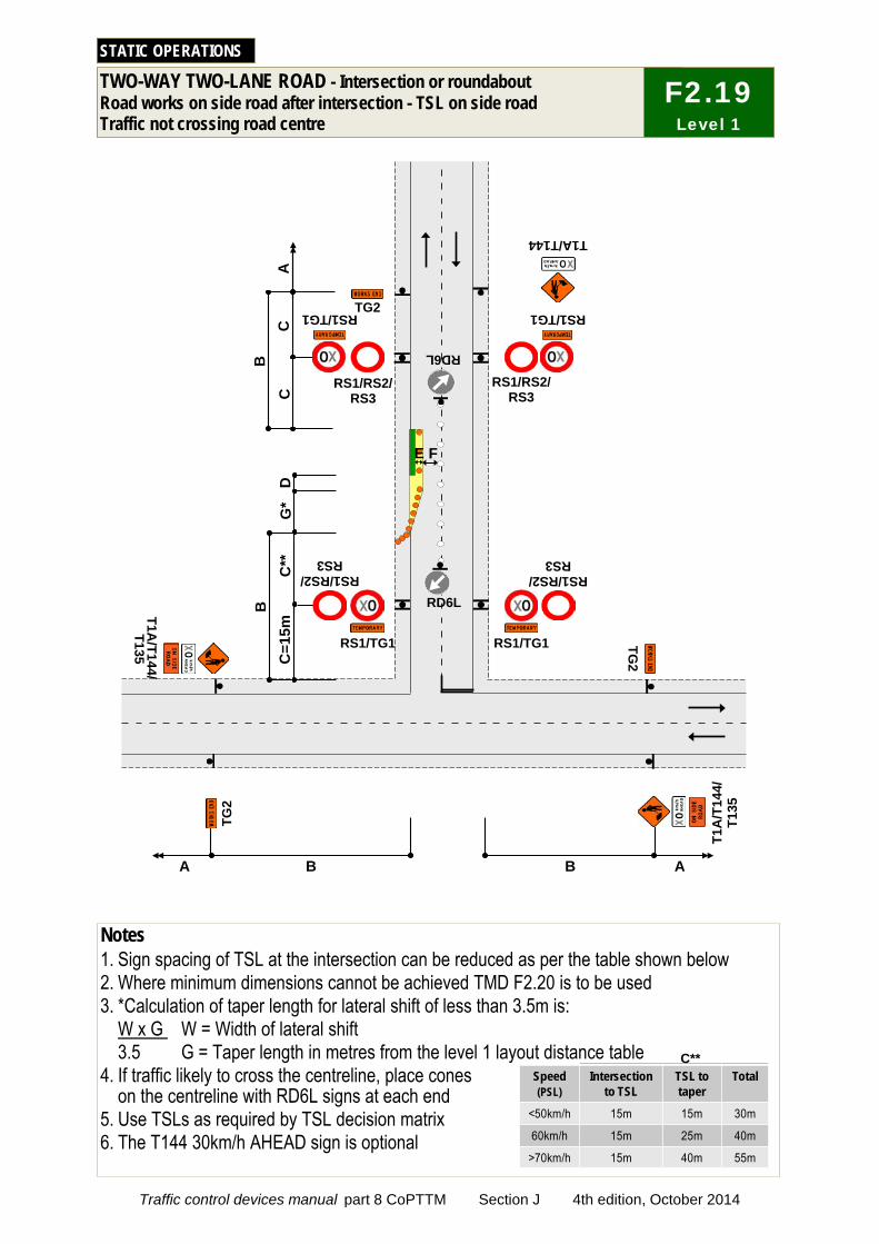
Speed Intersection to TSL
TSL to taper
Total
<50km/h 15m 15m 30m
60km/h 15m 25m 40m
>70km/h 15m 40m 55m
C**
(PSL)
TWO-WAY TWO-LANE ROAD - Intersection or roundabout Road works on side road after intersection - TSL on side road Traffic not crossing road centre
STATIC OPERATIONS
Notes 1. Sign spacing of TSL at the intersection can be reduced as per the table shown below 2. Where minimum dimensions cannot be achieved TMD F2.20 is to be used 3. *Calculation of taper length for lateral shift of less than 3.5m is:
W x G W = Width of lateral shift 3.5 G = Taper length in metres from the level 1 layout distance table
4. If traffic likely to cross the centreline, place cones on the centreline with RD6L signs at each end
5. Use TSLs as required by TSL decision matrix 6. The T144 30km/h AHEAD sign is optional
F2.19 Level 1
C
TG2
TG2
D
G*
C**
C
=15m
C
A
E F
B
A
B
B
A
B
TG2
RD6L
RD6L
RS1/RS2/ RS3
RS1/RS2/ RS3
RS1/TG1
T1A/T144
RS1/TG1
T1A
/T14
4/
T135
T1A
/T144/ T135
RS1/RS2/ RS3
RS1/TG1
RS1/RS2/ RS3
RS1/TG1
Traffic control devices manual part 8 CoPTTM Section J 4th edition, October 2014
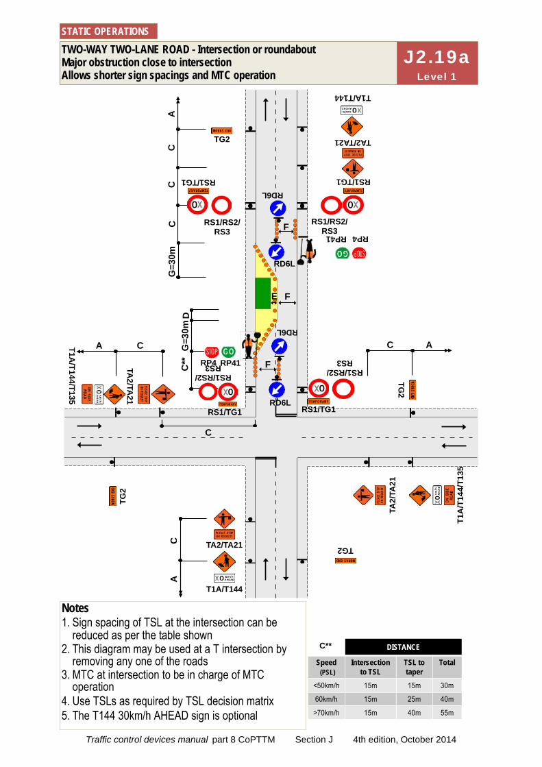
C
A
TWO-WAY TWO-LANE ROAD - Intersection or roundabout Major obstruction close to intersection Allows shorter sign spacings and MTC operation
STATIC OPERATIONS
Notes 1. Sign spacing of TSL at the intersection can be
reduced as per the table shown 2. This diagram may be used at a T intersection by
removing any one of the roads 3. MTC at intersection to be in charge of MTC
operation 4. Use TSLs as required by TSL decision matrix 5. The T144 30km/h AHEAD sign is optional
C
A
C
TG2
A
T1A/T144/T135
C
TG2
TG2
TG2
TA2/
TA21
TA2/TA
21
T1A/T144
TA2/TA21
RS1/RS2/ RS3
RS1/TG1 RD6L
RD6L
RD6L
C
RP41 RP4
F
F
F
T1A/T144
T1A
/T14
4/T1
35
RS1/RS2/ RS3
RS1/TG1
TA2/TA21
C
C
RS1/RS2/ RS3
RS1/TG1
A
D
G=3
0m
C**
E
RP41 RP4
RS1/RS2/ RS3
RS1/TG1
G=3
0m
RD6L
J2.19a Level 1
DISTANCE
Speed Intersection to TSL
TSL to taper
Total
<50km/h 15m 15m 30m
60km/h 15m 25m 40m
>70km/h 15m 40m 55m
C**
(PSL)
Traffic control devices manual part 8 CoPTTM Section J 4th edition, October 2014
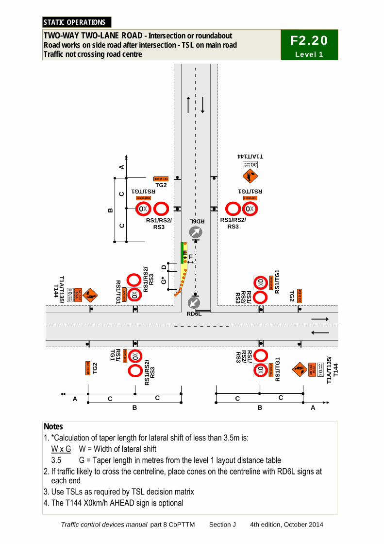
TWO-WAY TWO-LANE ROAD - Intersection or roundabout Road works on side road after intersection - TSL on main road Traffic not crossing road centre
STATIC OPERATIONS
Notes 1. *Calculation of taper length for lateral shift of less than 3.5m is:
W x G W = Width of lateral shift 3.5 G = Taper length in metres from the level 1 layout distance table
2. If traffic likely to cross the centreline, place cones on the centreline with RD6L signs at each end
3. Use TSLs as required by TSL decision matrix 4. The T144 X0km/h AHEAD sign is optional
C
TG2
TG2
D
G*
T1A/T144
RS1/RS2/ RS3
RS1/TG1
C
RS1/RS2/ RS3
RS1/TG1
A
E
B
A
B
A B
TG2
RS1/
TG1
RS1/TG
1
RS1/
RS2/
RS3
RS1
/TG
1 R
S1/T
G1
C
C
C
C
F
RD6L RD6L
RS1
/RS2
/ R
S3
RS1/
RS2/
RS3
RS1
/RS2
/ R
S3
F2.20 Level 1
T1A/T135/
T144 T1
A/T
135/
T1
44
Traffic control devices manual part 8 CoPTTM Section J 4th edition, October 2014
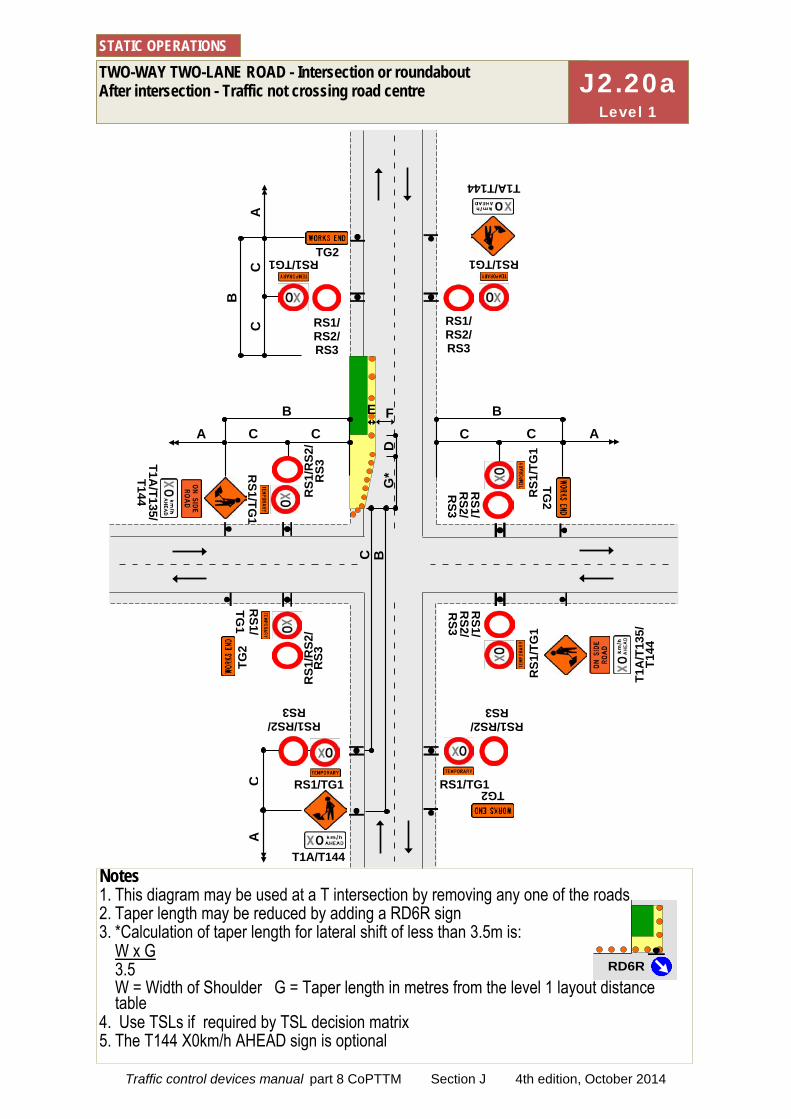
RD6R
TWO-WAY TWO-LANE ROAD - Intersection or roundabout After intersection - Traffic not crossing road centre
STATIC OPERATIONS
Notes 1. This diagram may be used at a T intersection by removing any one of the roads 2. Taper length may be reduced by adding a RD6R sign 3. *Calculation of taper length for lateral shift of less than 3.5m is:
W x G 3.5 W = Width of Shoulder G = Taper length in metres from the level 1 layout distance table
4. Use TSLs if required by TSL decision matrix 5. The T144 X0km/h AHEAD sign is optional
C
C
BA
C
C
B
RS1/ RS2/ RS3
RS1/ RS2/ RS3
RS1/TG1 RS1/TG1
A
T1A/T144
C
T1A/T144
RS1/RS2/ RS3
RS1/RS2/ RS3
RS1/TG1
A
B
TG2
RS1
/RS2
/ R
S3
RS1
/RS2
/ R
S3
RS1/
TG1
RS1/TG
1
T1A
/T13
5/T1
44
T1A/T135/
T144
RS1/TG1
TG2
TG2
TG2
RS1/
RS2/
RS3
RS1
/TG
1
RS1/
RS2/
RS3
RS1
/TG
1
E F
D
G*
B C
C
C
A
J2.20a Level 1
Traffic control devices manual part 8 CoPTTM Section J 4th edition, October 2014
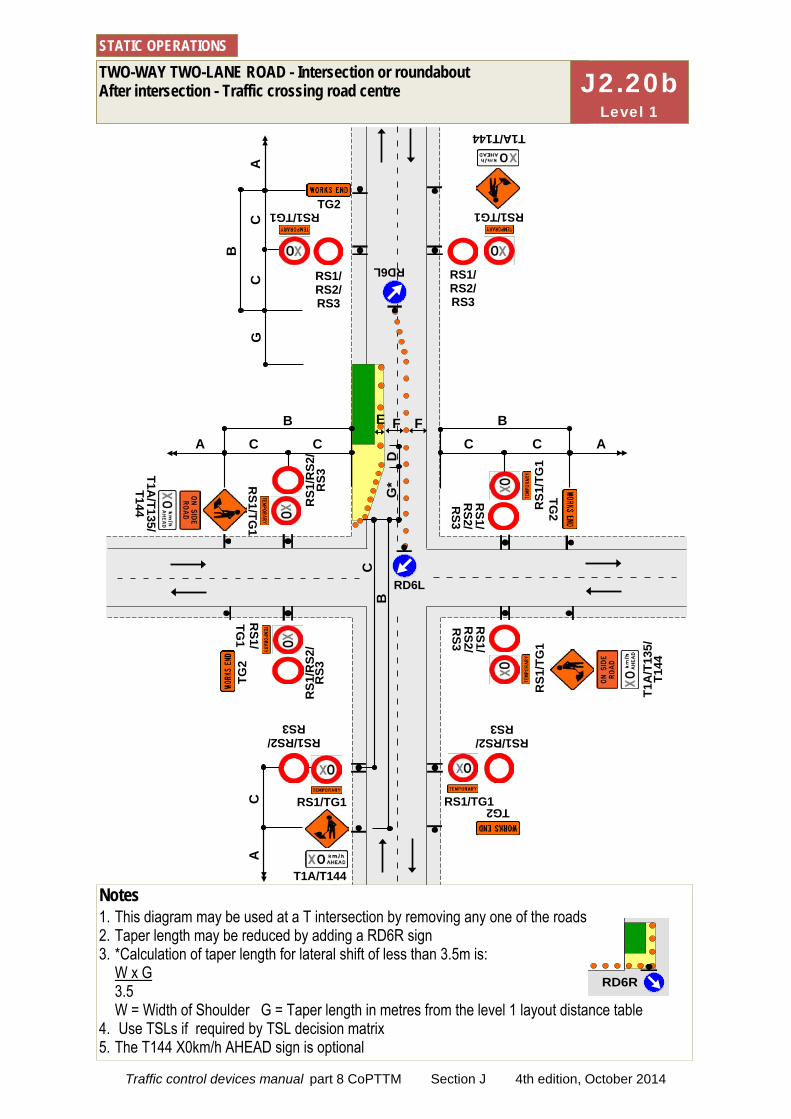
C
C
BA
C
C
B
RS1/ RS2/ RS3
RS1/ RS2/ RS3
RS1/TG1 RS1/TG1
A
T1A/T144
C
T1A/T144
RS1/RS2/ RS3
RS1/RS2/ RS3
RS1/TG1
A
B
TG2
RS1
/RS2
/ R
S3
RS1
/RS2
/ R
S3
RS1/
TG1
RS1/TG
1
T1A
/T13
5/T1
44
T1A/T135/
T144
RS1/TG1
G
TG2
TG2
TG2
RS1/
RS2/
RS3
RS1
/TG
1
RS1/
RS2/
RS3
RS1
/TG
1
E F
D
G*
B
C
C
C
A
TWO-WAY TWO-LANE ROAD - Intersection or roundabout After intersection - Traffic crossing road centre
STATIC OPERATIONS
RD6L
RD6L
F
Notes 1. This diagram may be used at a T intersection by removing any one of the roads 2. Taper length may be reduced by adding a RD6R sign 3. *Calculation of taper length for lateral shift of less than 3.5m is:
W x G 3.5 W = Width of Shoulder G = Taper length in metres from the level 1 layout distance table
4. Use TSLs if required by TSL decision matrix 5. The T144 X0km/h AHEAD sign is optional
RD6R
J2.20b Level 1
Traffic control devices manual part 8 CoPTTM Section J 4th edition, October 2014
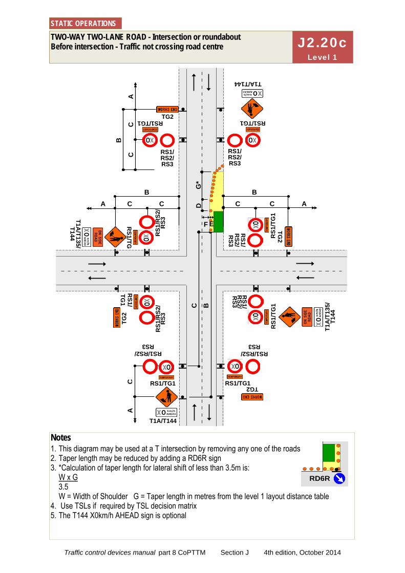
C
C
BA
C
C
B
RS1/ RS2/ RS3
RS1/ RS2/ RS3
RS1/TG1 RS1/TG1
A
T1A/T144
C
T1A/T144
RS1/RS2/ RS3
RS1/RS2/ RS3
RS1/TG1
A
C
C
B
TG2
RS1
/RS2
/ R
S3
RS1
/RS2
/ R
S3
RS1/
TG1
RS1/TG
1
A
T1A
/T13
5/T1
44
T1A/T135/
T144
RS1/TG1
TG2
TG2
TG2
RS1/
RS2/
RS3
RS1
/TG
1
RS1/
RS2/
RS3
RS1
/TG
1
TWO-WAY TWO-LANE ROAD - Intersection or roundabout Before intersection - Traffic not crossing road centre
STATIC OPERATIONS
B
C
E F
D
G*
Notes 1. This diagram may be used at a T intersection by removing any one of the roads 2. Taper length may be reduced by adding a RD6R sign 3. *Calculation of taper length for lateral shift of less than 3.5m is:
W x G 3.5 W = Width of Shoulder G = Taper length in metres from the level 1 layout distance table
4. Use TSLs if required by TSL decision matrix 5. The T144 X0km/h AHEAD sign is optional
RD6R
J2.20c Level 1
Traffic control devices manual part 8 CoPTTM Section J 4th edition, October 2014
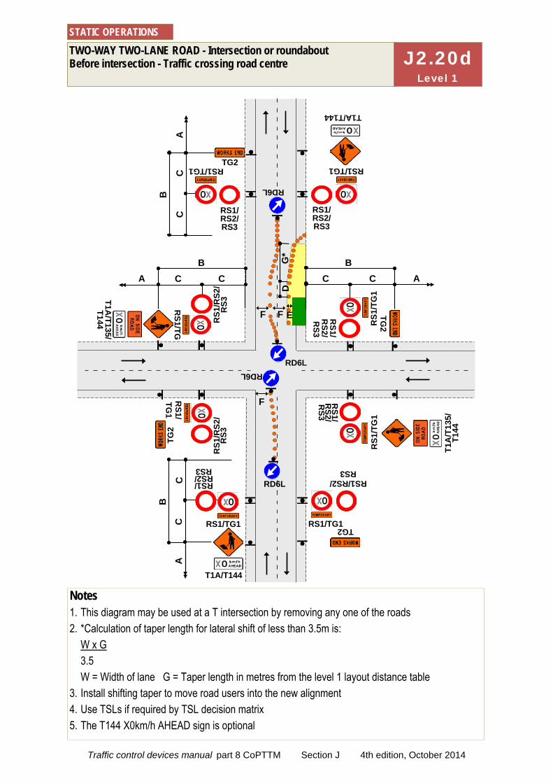
C
C
BA
C
C
B
RS1/ RS2/ RS3
RS1/ RS2/ RS3
RS1/TG1 RS1/TG1
A
T1A/T144
C
T1A/T144
RS1/ RS2/ RS3
RS1/RS2/ RS3
RS1/TG1
A
C
C
B
TG2
RS1
/RS2
/ R
S3
RS1
/RS2
/ R
S3
RS1/
TG1
RS1/TG
1
A
T1A
/T13
5/T1
44
T1A/T135/
T144
RS1/TG1
TG2
TG2
TG2
RS1/
RS2/
RS3
RS1
/TG
1
RS1/
RS2/
RS3
RS1
/TG
1
RD6L
RD6L F
C
B
TWO-WAY TWO-LANE ROAD - Intersection or roundabout Before intersection - Traffic crossing road centre
STATIC OPERATIONS
Notes 1. This diagram may be used at a T intersection by removing any one of the roads 2. *Calculation of taper length for lateral shift of less than 3.5m is:
W x G 3.5 W = Width of lane G = Taper length in metres from the level 1 layout distance table
3. Install shifting taper to move road users into the new alignment 4. Use TSLs if required by TSL decision matrix 5. The T144 X0km/h AHEAD sign is optional
RD6L
F E F
D
G*
RD6L
J2.20d Level 1
Traffic control devices manual part 8 CoPTTM Section J 4th edition, October 2014

C
C
BA
C
T1A/T144
RS1/ RS2/ RS3
RS1/RS2/ RS3
RS1/TG1
A
C
C
B
TG2
RS1
/RS2
/ R
S3
RS1
/RS2
/ R
S3
RS1/TG
1 R
S1/TG1
A
T1A
/T13
5/T1
44
T1A/T135/
T144
RS1/TG1 TG2
TG2
RS1/
RS2/
RS3
RS1
/TG
1
RS1/
RS2/
RS3
RS1
/TG
1
RD6L
RD6L F
C
B
TWO-WAY TWO-LANE ROAD - Intersection or roundabout On median near intersection
STATIC OPERATIONS
Notes 1. This diagram may be used at a T intersection by removing any one of the roads 2. *Calculation of taper length for lateral shift of less than 3.5m is:
W x G 3.5 W = Width of lane G = Taper length in metres from the level 1 layout distance table
3. Install shifting taper to move road users into the new alignment 4. Use TSLs if required by TSL decision matrix 5. The T144 X0km/h AHEAD sign is optional
D
G*
E F
RD6L
E F
RD6L
½C
C
C
B
RS1/ RS2/ RS3
RS1/ RS2/ RS3
RS1/TG1 RS1/TG1
A
T1A/T144
TG2
D
G*
J2.20e Level 1
Traffic control devices manual part 8 CoPTTM Section J 4th edition, October 2014

TWO-WAY TWO-LANE ROAD - Intersection or roundabout Work in middle of intersection
STATIC OPERATIONS
TG2
T1A/T144
RS1/RS2/ RS3
RS1/RS2/ RS3
RS1/TG1 RS1/TG1
C
C
A
B
F F
RD6L
F
F F
Signs and layout to be repeated on each approach
Notes 1. This diagram may be used at a T intersection by removing any one of the roads 2. Signs and layout shown in the box at the bottom of the diagram is to be repeated on each
approach 3. RD6L signs are not required at an existing roundabout 4. Cone tapers are optional at existing roundabouts 5. Lane widths, F, may need to be increased to allow for turning movements of larger vehicles 6. Use TSLs if required by TSL decision matrix 7. The T144 X0km/h AHEAD sign is optional
F2.21 Level 1
Traffic control devices manual part 8 CoPTTM Section J 4th edition, October 2014
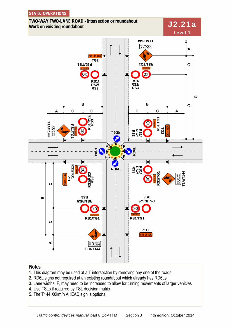
C
C
BA
RS1/ RS2/ RS3
RS1/ RS2/ RS3
RS1/TG1 RS1/TG1
T1A/T144
RS1/RS2/ RS3
RS1/TG1
A
C
C
B
TG2
RS1
/RS2
/ R
S3
RS1
/RS2
/ R
S3
RS1/TG
1 R
S1/TG1
A
T1A
/T14
4 T1A
/T144
RS1/TG1
TG2
TG2
TG2
RS1/
RS2/
RS3
RS1
/TG
1
RS1/
RS2/
RS3
RS1
/TG
1
TWO-WAY TWO-LANE ROAD - Intersection or roundabout Work on existing roundabout
STATIC OPERATIONS
Notes 1. This diagram may be used at a T intersection by removing any one of the roads 2. RD6L signs not required at an existing roundabout which already has RD6Ls 3. Lane widths, F, may need to be increased to allow for turning movements of larger vehicles 4. Use TSLs if required by TSL decision matrix 5. The T144 X0km/h AHEAD sign is optional
C
C
C
B
A
F
C
B
F
RD
6L RD
6L
RS1/RS2/ RS3
E
RD6L
RD6L
F
F
F
T1A/T144
J2.21a Level 1
Traffic control devices manual part 8 CoPTTM Section J 4th edition, October 2014

Notes 1. This diagram may be
used at a T intersection by removing any one of the roads
2. Signs and layout shown in the box at the bottom of the diagram is to be repeated on each approach
3. A 30m return taper at the end of the closure is mandatory
4. Use PN11 no stopping signs, if necessary
5. MTC with RP4/RP41 STOP/GO or RP4/RP42 STOP/SLOW paddle on road shoulder located between 1st and 2nd cone in the cone threshold closest to the working space
6. Minimum 5 cones in cone threshold at: 2.5m centres -
less than 65km/h 5m centres - more
than 65km/h 7. Refer to C10.2.3
MTC essentials for further information
8. On roads with a permanent speed limit of 100km/h, cones are required from the TSL to the taper if the speed is reduced by more than 30km/h
9. The T144 30km/h AHEAD sign is optional
TWO-WAY TWO-LANE ROAD - Intersection or roundabout Closure at corner of an intersection Manual traffic control (Stop/Go or Stop/Slow)
STATIC OPERATIONS
TG2
RS1/RS2/ RS3
RS1/RS2/ RS3
RS1/TG1 RS1/TG1
C
C
D
C
G=30m
TA2/TA21
RP41 RP4
RP41
RP4
RP4
1 R
P4
RP41 RP4
F
F E
A
RD
6L RD
6L
RD6R E
Signs and layout to be repeated on each approach
10m
F
RD6L
RD6L
F
RD
6L RD
6L
10m RD6L
RD6L
10m F
D G
=30m
T1A/T144
F2.22 Level 1
Traffic control devices manual part 8 CoPTTM Section J 4th edition, October 2014
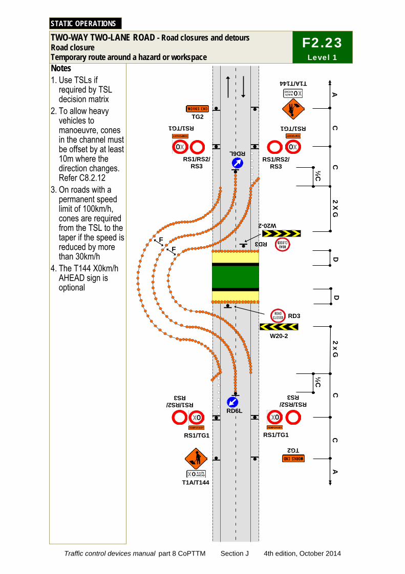
Notes 1. Use TSLs if
required by TSL decision matrix
2. To allow heavy vehicles to manoeuvre, cones in the channel must be offset by at least 10m where the direction changes. Refer C8.2.12
3. On roads with a permanent speed limit of 100km/h, cones are required from the TSL to the taper if the speed is reduced by more than 30km/h
4. The T144 X0km/h AHEAD sign is optional
TWO-WAY TWO-LANE ROAD - Road closures and detours Road closure Temporary route around a hazard or workspace
STATIC OPERATIONS
RD6L
C
C
C
D
TG2 TG2
T1A/T144 T1A/T144
RS1/RS2/ RS3
RS1/RS2/ RS3
RS1/RS2/ RS3
RS1/RS2/
RS3
RS1/TG1 RS1/TG1
RS1/TG1 RS1/TG1
F F
RD6L
2 X G
2 x G
A
A
C
½C
½
C
RD3
W20-2 RD3
W20-2
D
F2.23 Level 1
Traffic control devices manual part 8 CoPTTM Section J 4th edition, October 2014
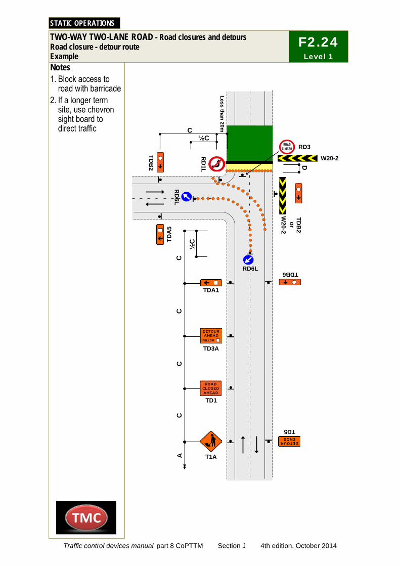
C
C
C
C
A
Notes 1. Block access to
road with barricade 2. If a longer term
site, use chevron sight board to direct traffic
TWO-WAY TWO-LANE ROAD - Road closures and detours
Road closure - detour route Example
STATIC OPERATIONS
C
T1A
TD1
TD3A
TDA1
TDA
5
TD5
TDB
2
TDB6
D
RD3 ½C
RD
6L
RD
1L
Less than 20m
W20-2
½C
RD6L
W20-2 or
TDB
2
F2.24 Level 1
Traffic control devices manual part 8 CoPTTM Section J 4th edition, October 2014
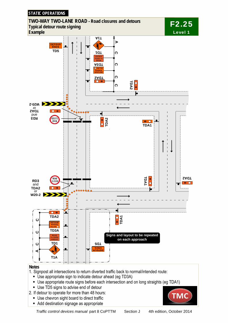
c
TWO-WAY TWO-LANE ROAD - Road closures and detours Typical detour route signing Example
STATIC OPERATIONS
TD5
A
TDA
1
T1A
TD3A C
C
TD5
C
TDA
2
T1A
TD3A C
C
A
C
TDA
1
TDA2
TDA1 TDA
2
TD1
TDA2
RD3
TDA2
W20-2 or
and
RD3
TDA2
W20-2 or
and
TD1
C
TDA2
Signs and layout to be repeated on each approach
F2.25 Level 1
Notes 1. Signpost all intersections to return diverted traffic back to normal/intended route: Use appropriate sign to indicate detour ahead (eg TD3A) Use appropriate route signs before each intersection and on long straights (eg TDA1) Use TD5 signs to advise end of detour
2. If detour to operate for more than 48 hours: Use chevron sight board to direct traffic Add destination signage as appropriate
Traffic control devices manual part 8 CoPTTM Section J 4th edition, October 2014
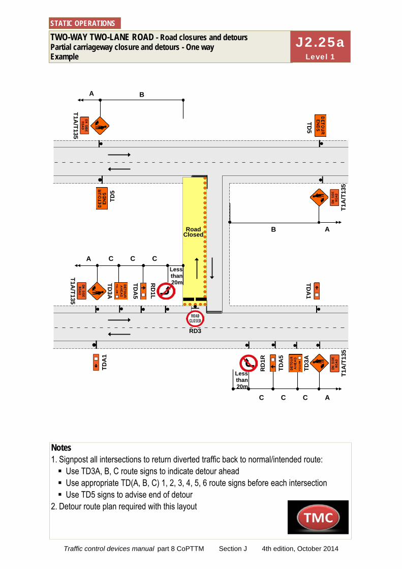
TWO-WAY TWO-LANE ROAD - Road closures and detours Partial carriageway closure and detours - One way Example
STATIC OPERATIONS
Notes 1. Signpost all intersections to return diverted traffic back to normal/intended route: Use TD3A, B, C route signs to indicate detour ahead Use appropriate TD(A, B, C) 1, 2, 3, 4, 5, 6 route signs before each intersection Use TD5 signs to advise end of detour
2. Detour route plan required with this layout
RD
3
J2.25a Level 1
Road Closed
T1A/T135
TDA
5
TD3A
RD
1L
C
A
C
C
T1A
/T13
5
TDA
5
TD3A
RD
1R
C A
CC
T1A/T135
A
B
T1A
/T13
5
A
B
TD5
TD5
Less than 20m
Less than 20m
RD3
TDA
1 TD
A1
Traffic control devices manual part 8 CoPTTM Section J 4th edition, October 2014
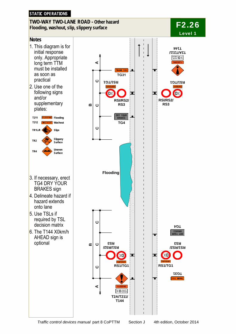
Washout
T211T212
Flooding
Uneven SurfaceTR4
TR1L/R Slips
TR2 Slippery Surface
C
C
RS1/RS2/ RS3
TG31
T2A/T211/ T144
RSI/RS2/ RS3
Notes 1. This diagram is for
initial response only. Appropriate long term TTM must be installed as soon as practical
2. Use one of the following signs and/or supplementary plates:
3. If necessary, erect TG4 DRY YOUR BRAKES sign
4. Delineate hazard if hazard extends onto lane
5. Use TSLs if required by TSL decision matrix
6. The T144 X0km/h AHEAD sign is optional
TWO-WAY TWO-LANE ROAD - Other hazard Flooding, washout, slip, slippery surface
STATIC OPERATIONS
C
C
RSI/RS2/ RS3
RS1/RS2/ RS3
B
B
TG4
TG4
RS1/TG1
RS1/TG1
RS1/TG1
RS1/TG1
T2A/T211/ T144
A
A
C
C
F2.26 Level 1
Flooding
Traffic control devices manual part 8 CoPTTM Section J 4th edition, October 2014
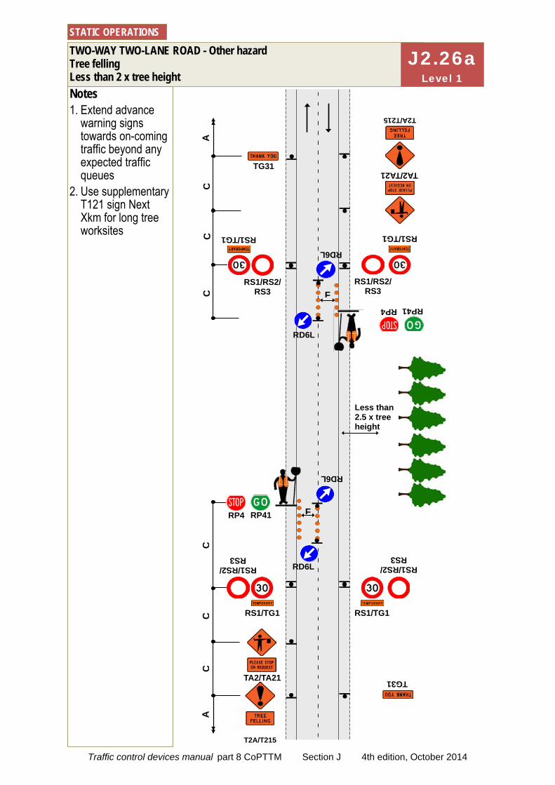
T2A/T215
RP41 RP4
Notes 1. Extend advance
warning signs towards on-coming traffic beyond any expected traffic queues
2. Use supplementary T121 sign Next Xkm for long tree worksites
TWO-WAY TWO-LANE ROAD - Other hazard Tree felling Less than 2 x tree height
STATIC OPERATIONS
C
C
C
C
RS1/RS2/ RS3
RS1/TG1
RS1/TG1
RS1/TG1
RS1/RS2/ RS3
RS1/TG1
C
C
RS1/RS2/ RS3
RS1/RS2/ RS3
TA2/TA21
F
RD6L F
TA2/TA21
RD6L
RP41 RP4
A
A
RD6L
RD6L
Less than 2.5 x tree height
T2A/T215
TG31
TG31
J2.26a Level 1
Traffic control devices manual part 8 CoPTTM Section J 4th edition, October 2014
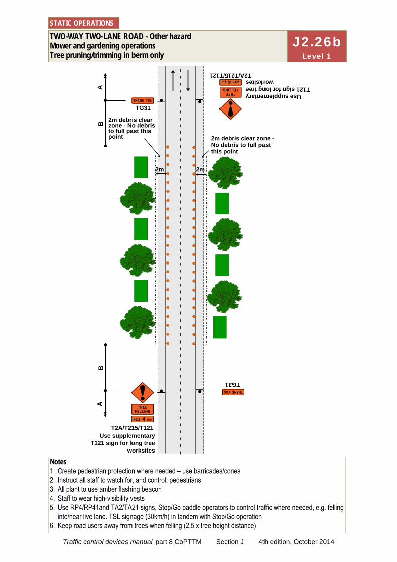
TWO-WAY TWO-LANE ROAD - Other hazard Mower and gardening operations Tree pruning/trimming in berm only
STATIC OPERATIONS
Notes 1. Create pedestrian protection where needed – use barricades/cones 2. Instruct all staff to watch for, and control, pedestrians 3. All plant to use amber flashing beacon 4. Staff to wear high-visibility vests 5. Use RP4/RP41and TA2/TA21 signs, Stop/Go paddle operators to control traffic where needed, e.g. felling
into/near live lane. TSL signage (30km/h) in tandem with Stop/Go operation 6. Keep road users away from trees when felling (2.5 x tree height distance)
A
T2A/T215/T121
A
T2A/T215/T121 Use supplementary
T121 sign for long tree worksites
B
B
Use supplementary T121 sign for long tree
worksites
2m debris clear zone - No debris to full past this point
TG31
TG31
2m debris clear zone - No debris to full past this point
2m 2m
J2.26b Level 1
Traffic control devices manual part 8 CoPTTM Section J 4th edition, October 2014
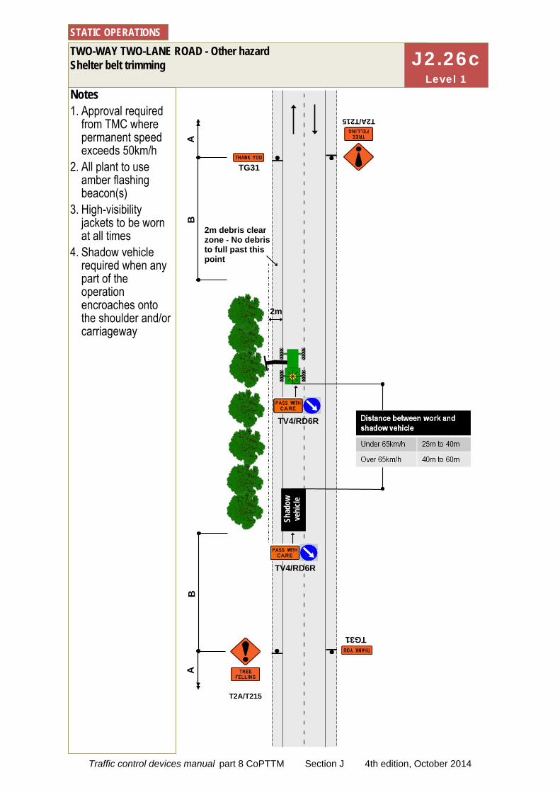
Notes 1. Approval required
from TMC where permanent speed exceeds 50km/h
2. All plant to use amber flashing beacon(s)
3. High-visibility jackets to be worn at all times
4. Shadow vehicle required when any part of the operation encroaches onto the shoulder and/or carriageway
T2A/T215
TWO-WAY TWO-LANE ROAD - Other hazard Shelter belt trimming
STATIC OPERATIONS
A
A
T2A/T215
TG31
TG31
TV4/RD6R
B
B
2m
Shad
ow
vehi
cle
TV4/RD6R
2m debris clear zone - No debris to full past this point
J2.26c Level 1
Traffic control devices manual part 8 CoPTTM Section J 4th edition, October 2014
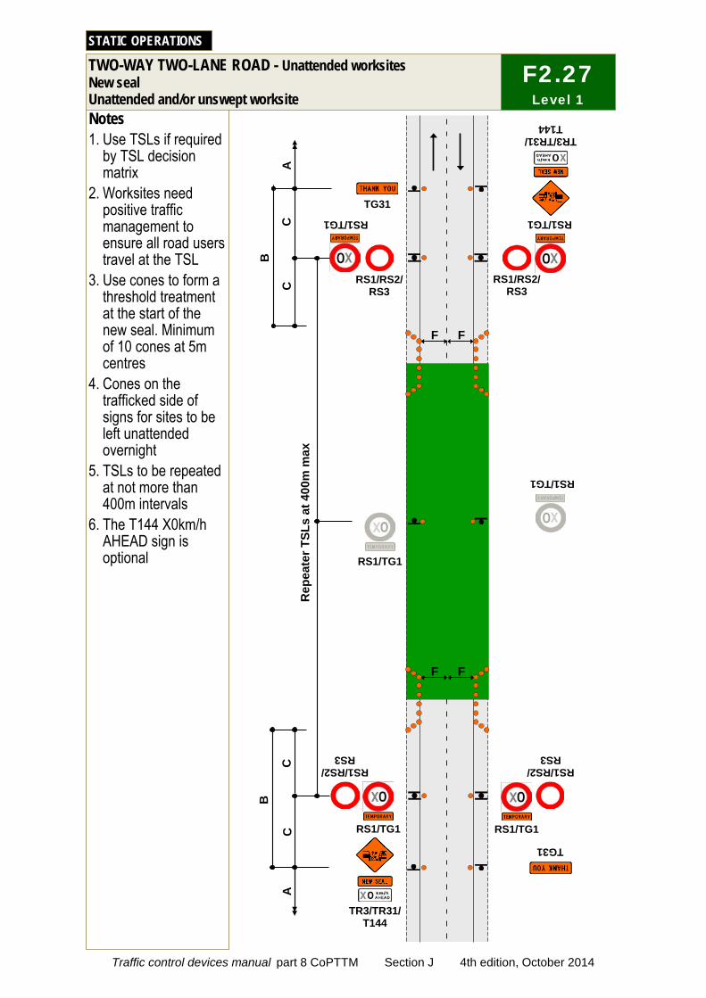
C
C
C
TG31
RS1/RS2/ RS3
Notes 1. Use TSLs if required
by TSL decision matrix
2. Worksites need positive traffic management to ensure all road users travel at the TSL
3. Use cones to form a threshold treatment at the start of the new seal. Minimum of 10 cones at 5m centres
4. Cones on the trafficked side of signs for sites to be left unattended overnight
5. TSLs to be repeated at not more than 400m intervals
6. The T144 X0km/h AHEAD sign is optional
TWO-WAY TWO-LANE ROAD - Unattended worksites New seal Unattended and/or unswept worksite
STATIC OPERATIONS
C
RS1/RS2/ RS3
RS1/RS2/ RS3
RS1/RS2/ RS3
B
B
TG31
RS1/TG1
RS1/TG1
RS1/TG1 RS1/TG1
RS1/TG1 RS1/TG1
TR3/TR31/ T144
TR3/TR31/ T144
A
A
Rep
eate
r TSL
s at
400
m m
ax
F F
F F
F2.27 Level 1
Traffic control devices manual part 8 CoPTTM Section J 4th edition, October 2014
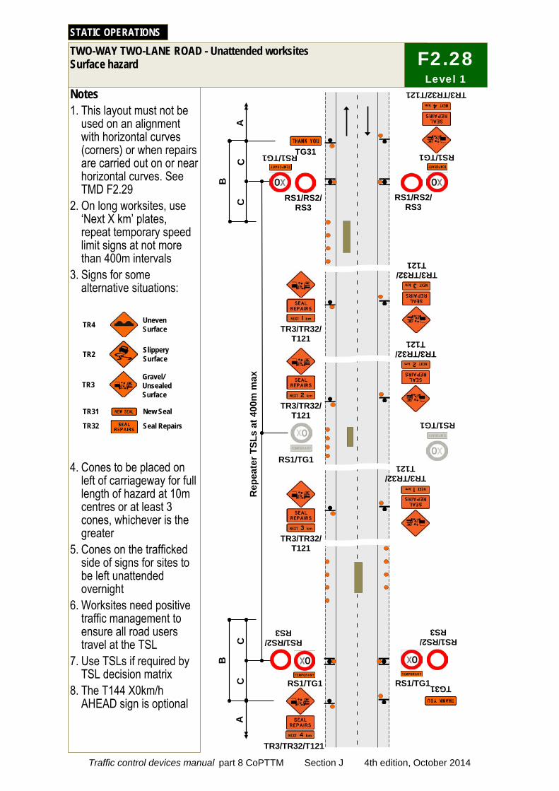
TR3/TR32/ T121
TR3/TR32/ T121
TR3Gravel/Unsealed Surface
New Seal
Seal Repairs
TR2 Slippery Surface
TR31
TR32
Uneven SurfaceTR4
C
Notes 1. This layout must not be
used on an alignment with horizontal curves (corners) or when repairs are carried out on or near horizontal curves. See TMD F2.29
2. On long worksites, use ‘Next X km’ plates, repeat temporary speed limit signs at not more than 400m intervals
3. Signs for some alternative situations:
4. Cones to be placed on left of carriageway for full length of hazard at 10m centres or at least 3 cones, whichever is the greater
5. Cones on the trafficked side of signs for sites to be left unattended overnight
6. Worksites need positive traffic management to ensure all road users travel at the TSL
7. Use TSLs if required by TSL decision matrix
8. The T144 X0km/h AHEAD sign is optional
TWO-WAY TWO-LANE ROAD - Unattended worksites Surface hazard
STATIC OPERATIONS
C
B
TG31 RS1/RS2/
RS3 RS1/RS2/
RS3
RS1/TG1 RS1/TG1
RS1/RS2/ RS3
RS1/RS2/ RS3
RS1/TG1 RS1/TG1
A
A
TG31
TR3/TR32/T121
TR3/TR32/T121
RS1/TG1
RS1/TG1
TR3/TR32/ T121
TR3/TR32/ T121
TR3/TR32/ T121
TR3/TR32/ T121
C
C
B
F2.28 Level 1
Rep
eate
r TSL
s at
400
m m
ax
Traffic control devices manual part 8 CoPTTM Section J 4th edition, October 2014
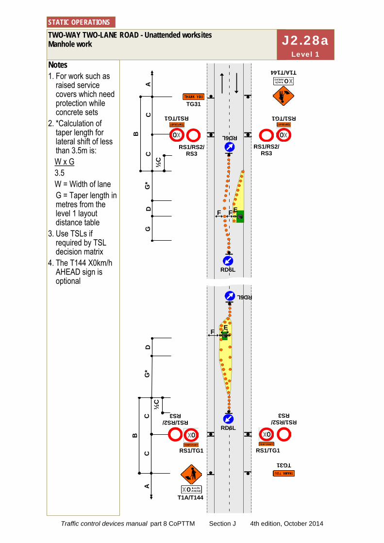
C
C
C
Notes 1. For work such as
raised service covers which need protection while concrete sets
2. *Calculation of taper length for lateral shift of less than 3.5m is: W x G 3.5 W = Width of lane G = Taper length in metres from the level 1 layout distance table
3. Use TSLs if required by TSL decision matrix
4. The T144 X0km/h AHEAD sign is optional
TWO-WAY TWO-LANE ROAD - Unattended worksites Manhole work
STATIC OPERATIONS
C
D
G*
B
B
TG31
T1A/T144
RS1/RS2/ RS3
RS1/RS2/ RS3
RS1/RS2/ RS3
RS1/RS2/ RS3
RS1/TG1
RS1/TG1
RS1/TG1
RS1/TG1
A
A
F
T1A/T144
E
D
G
G*
F
TG31
RD6L
RD6L
F
RD6L
RD6L
½C
½
C
E
J2.28a Level 1
Traffic control devices manual part 8 CoPTTM Section J 4th edition, October 2014
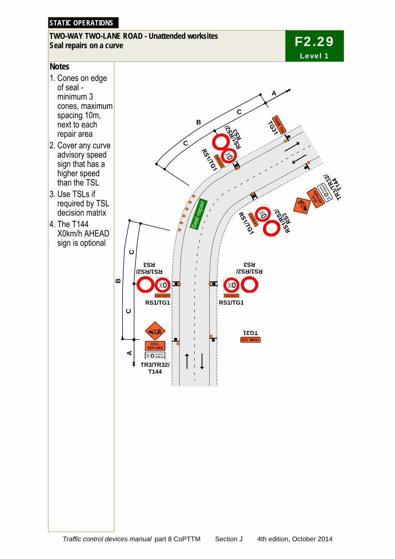
Notes 1. Cones on edge
of seal - minimum 3 cones, maximum spacing 10m, next to each repair area
2. Cover any curve advisory speed sign that has a higher speed than the TSL
3. Use TSLs if required by TSL decision matrix
4. The T144 X0km/h AHEAD sign is optional
TWO-WAY TWO-LANE ROAD - Unattended worksites Seal repairs on a curve
STATIC OPERATIONS
C
C
C
C
A
TG31
RS1/RS2/ RS3
RS1/TG1 RS1/TG1
RS1/RS2/ RS3
TR3/TR32/ T144
A
B
B
F2.29 Level 1
Traffic control devices manual part 8 CoPTTM Section J 4th edition, October 2014

Notes 1. Use TSLs if
required by TSL decision matrix
2. On roads with a permanent speed limit of 100km/h, cones are required from the TSL to the taper if the speed is reduced by more than 30km/h
3. The T144 X0km/h AHEAD sign is optional
ONE-WAY TWO-LANE DIVIDED OR TWO-LANE ROAD Left-lane closure
STATIC OPERATIONS
D
C
C
C
G
C TL2L TL2L
T1A/T144 T1A/T144
A
RS1/TG1 RS1/TG1
TG2
RS1/RS2/ RS3
TG2
RS1/RS2/ RS3
F E
RD6R
F2.30 Level 1
Traffic control devices manual part 8 CoPTTM Section J 4th edition, October 2014
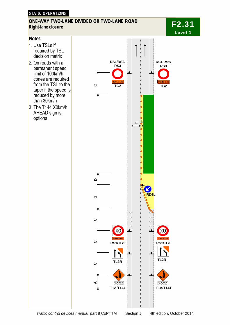
Notes 1. Use TSLs if
required by TSL decision matrix
2. On roads with a permanent speed limit of 100km/h, cones are required from the TSL to the taper if the speed is reduced by more than 30km/h
3. The T144 X0km/h AHEAD sign is optional
ONE-WAY TWO-LANE DIVIDED OR TWO-LANE ROAD Right-lane closure
STATIC OPERATIONS
D
C
C
C
G
C
T1A/T144 T1A/T144
A
RS1/TG1 RS1/TG1
TG2
RS1/RS2/ RS3
TG2
RS1/RS2/ RS3
TL2R TL2R
F E
RD6L
F2.31 Level 1
Traffic control devices manual part 8 CoPTTM Section J 4th edition, October 2014
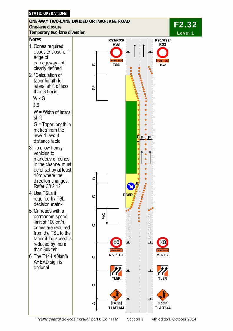
D
C
C
G
Notes 1. Cones required
opposite closure if edge of carriageway not clearly defined
2. *Calculation of taper length for lateral shift of less than 3.5m is: W x G 3.5 W = Width of lateral shift G = Taper length in metres from the level 1 layout distance table
3. To allow heavy vehicles to manoeuvre, cones in the channel must be offset by at least 10m where the direction changes. Refer C8.2.12
4. Use TSLs if required by TSL decision matrix
5. On roads with a permanent speed limit of 100km/h, cones are required from the TSL to the taper if the speed is reduced by more than 30km/h
6. The T144 X0km/h AHEAD sign is optional
ONE-WAY TWO-LANE DIVIDED OR TWO-LANE ROAD One-lane closure Temporary two-lane diversion
STATIC OPERATIONS
C
T1A/T144 T1A/T144
C
TL5R TL5R
A
RS1/TG1 RS1/TG1
TG2
RS1/RS2/ RS3
TG2
RS1/RS2/ RS3
E F F
½C
RD6R
G*
F2.32 Level 1
Traffic control devices manual part 8 CoPTTM Section J 4th edition, October 2014
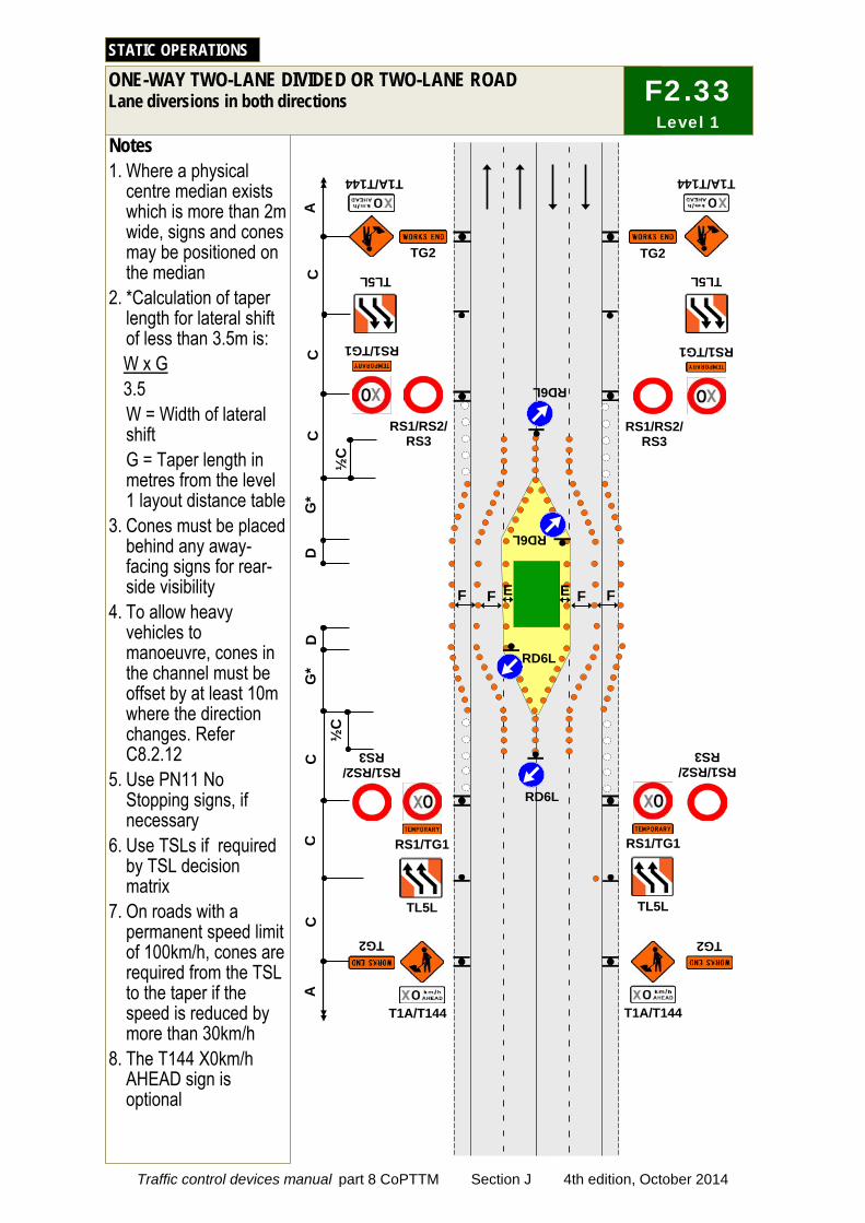
Notes 1. Where a physical
centre median exists which is more than 2m wide, signs and cones may be positioned on the median
2. *Calculation of taper length for lateral shift of less than 3.5m is: W x G 3.5 W = Width of lateral shift G = Taper length in metres from the level 1 layout distance table
3. Cones must be placed behind any away-facing signs for rear-side visibility
4. To allow heavy vehicles to manoeuvre, cones in the channel must be offset by at least 10m where the direction changes. Refer C8.2.12
5. Use PN11 No Stopping signs, if necessary
6. Use TSLs if required by TSL decision matrix
7. On roads with a permanent speed limit of 100km/h, cones are required from the TSL to the taper if the speed is reduced by more than 30km/h
8. The T144 X0km/h AHEAD sign is optional
ONE-WAY TWO-LANE DIVIDED OR TWO-LANE ROAD Lane diversions in both directions
STATIC OPERATIONS
C
C
RS1/RS2/ RS3
TG2
T1A/T144
RS1/TG1
T1A/T144
RS1/RS2/ RS3
TG2
A
RS1/TG1
RS1/RS2/ RS3
RS1/TG1
RS1/RS2/ RS3 C
TG2
A
RS1/TG1
T1A/T144 T1A/T144
TG2
RD6L
D
G*
G*
C
C
TL5L TL5L
½C
½
C
D
RD6L
E
TL5L TL5L
F E F
RD6L RD6L
F F
C
F2.33 Level 1
Traffic control devices manual part 8 CoPTTM Section J 4th edition, October 2014

Notes 1. Where a physical
centre median exists which is more than 2m wide, signs and cones may be positioned on the median
2. *Calculation of taper length for lateral shift of less than 3.5m is: W x G 3.5 W = Width of lateral shift G = Taper length in metres from the level 1 layout distance table
3. Cones must be placed behind any away-facing signs for rear-side visibility
4. To allow heavy vehicles to manoeuvre, cones in the channel must be offset by at least 10m where the direction changes. Refer C8.2.12
5. Use PN11 No Stopping signs, if necessary
6. Use TSLs if required by TSL decision matrix
7. On roads with a permanent speed limit of 100km/h, cones are required from the TSL to the taper if the speed is reduced by more than 30km/h
8. The T144 X0km/h AHEAD sign is optional
TWO-LANE DIVIDED OR TWO-LANE ONE-WAY ROAD Lanes diverted
STATIC OPERATIONS
E
C
C
RS1/RS2/ RS3
TG2
T1A/T144
RS1/TG1
T1A/T144
RS1/RS2/ RS3
TG2
A
RS1/TG1
RS1/RS2/ RS3
RS1/TG1
RS1/RS2/ RS3 C
TG2
A
RS1/TG1
T1A/T144 T1A/T144
TG2
RD6L
D
G*
G*
C
E
C
TL5L TL5L
½C
D
RD6L
F F
½C
RD6L
J2.33a Level 1
Traffic control devices manual part 8 CoPTTM Section J 4th edition, October 2014

C
C
Notes 1. Use either TMD F2.32
or TMD F2.33 in preference to this TMD, unless their use would likely cause traffic delays
2. Cones are required on edge of the temporary lane opposite closure if road is not well defined
3. *Calculation of taper length for lateral shift of less than 3.5m is: W x G 3.5 W = Width of lateral shift G = Taper length in metres from the level 1 layout distance table
4. To allow heavy vehicles to manoeuvre, cones in the channel must be offset by at least 10m where the direction changes. Refer C8.2.12
5. Use PN11 No Stopping signs, if necessary
6. Use TSLs if required by TSL decision matrix
7. On roads with a permanent speed limit of 100km/h, cones are required from the TSL to the taper if the speed is reduced by more than 30km/h
8. The T144 X0km/h AHEAD sign is optional
ONE-WAY TWO-LANE DIVIDED OR TWO-LANE ROAD Work in middle of road
STATIC OPERATIONS
C
D
G*
B
T1A/T144
RS1/TG1
A
E
T1A/T144
F
PN11
PN11
PN11
TG2
RS1/RS2/ RS3
TG2
RS1/RS2/ RS3
RS1/TG1
RD6R
E
RD6L
F
F2.34 Level 1
Traffic control devices manual part 8 CoPTTM Section J 4th edition, October 2014
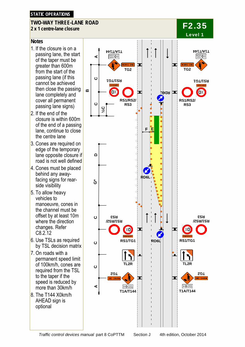
Notes 1. If the closure is on a
passing lane, the start of the taper must be greater than 600m from the start of the passing lane (if this cannot be achieved then close the passing lane completely and cover all permanent passing lane signs)
2. If the end of the closure is within 600m of the end of a passing lane, continue to close the centre lane
3. Cones are required on edge of the temporary lane opposite closure if road is not well defined
4. Cones must be placed behind any away-facing signs for rear-side visibility
5. To allow heavy vehicles to manoeuvre, cones in the channel must be offset by at least 10m where the direction changes. Refer C8.2.12
6. Use TSLs as required by TSL decision matrix
7. On roads with a permanent speed limit of 100km/h, cones are required from the TSL to the taper if the speed is reduced by more than 30km/h
8. The T144 X0km/h AHEAD sign is optional
TWO-WAY THREE-LANE ROAD 2 x 1 centre-lane closure
STATIC OPERATIONS
C
C
RD6L
T1A/T144
RS1/TG1
TG2
RS1/RS2/ RS3
TG2
RS1/RS2/ RS3
T1A/T144
RS1/TG1
A
C
C
D
C
G*
RS1/RS2/ RS3
TG2
TL2R
T1A/T144
RS1/TG1 RS1/TG1
TL2R
T1A/T144
RS1/RS2/ RS3
TG2
RD6L
A
B
RD6L
F E
½C
F2.35 Level 1
Traffic control devices manual part 8 CoPTTM Section J 4th edition, October 2014
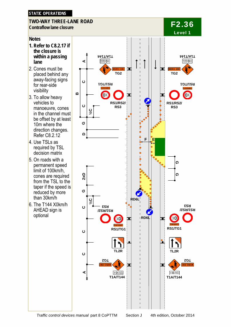
Notes 1. Refer to C8.2.17 if
the closure is within a passing lane
2. Cones must be placed behind any away-facing signs for rear-side visibility
3. To allow heavy vehicles to manoeuvre, cones in the channel must be offset by at least 10m where the direction changes. Refer C8.2.12
4. Use TSLs as required by TSL decision matrix
5. On roads with a permanent speed limit of 100km/h, cones are required from the TSL to the taper if the speed is reduced by more than 30km/h
6. The T144 X0km/h AHEAD sign is optional
TWO-WAY THREE-LANE ROAD Contraflow lane closure
STATIC OPERATIONS
F2.36 Level 1
C
C
T1A/T144
RS1/TG1
TG2
RS1/RS2/ RS3
TG2
RS1/RS2/ RS3
T1A/T144
RS1/TG1
TG2
TL2R
T1A/T144
TL2R
T1A/T144
C
C
C
RS1/RS2/ RS3
RS1/TG1 RS1/TG1
RS1/RS2/ RS3
TG2
2xD
G
B
G
D
F E
RD6L
A
A
½C
RD6L
½C
G
G
Traffic control devices manual part 8 CoPTTM Section J 4th edition, October 2014
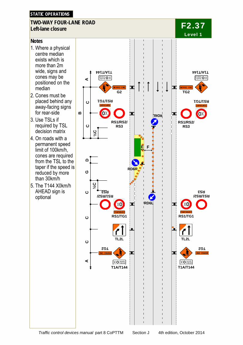
Notes 1. Where a physical
centre median exists which is more than 2m wide, signs and cones may be positioned on the median
2. Cones must be placed behind any away-facing signs for rear-side
3. Use TSLs if required by TSL decision matrix
4. On roads with a permanent speed limit of 100km/h, cones are required from the TSL to the taper if the speed is reduced by more than 30km/h
5. The T144 X0km/h AHEAD sign is optional
TWO-WAY FOUR-LANE ROAD Left-lane closure
STATIC OPERATIONS
C
C
C
RS1/RS2/ RS3
TG2
T1A/T144
RS1/TG1
T1A/T144
RS1/RS2/ RS3
TG2
A
RS1/TG1
RS1/RS2/ RS3
RS1/TG1
RS1/RS2/ RS3
C
G2 C
A
RS1/TG1
T1A/T144 T1A/T144
TG2
RD6L
D
G
TL2L TL2L
B
F E
RD6R
½C
RD6L
½C
F2.37 Level 1
Traffic control devices manual part 8 CoPTTM Section J 4th edition, October 2014
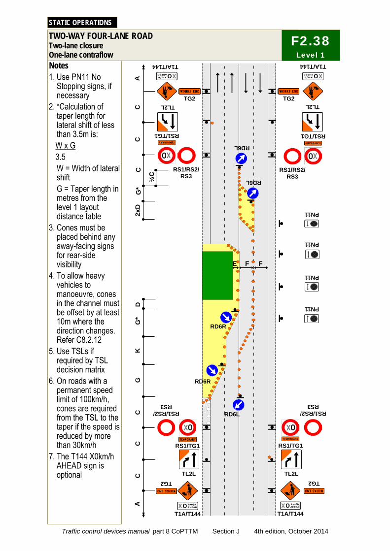
Notes 1. Use PN11 No
Stopping signs, if necessary
2. *Calculation of taper length for lateral shift of less than 3.5m is: W x G 3.5 W = Width of lateral shift G = Taper length in metres from the level 1 layout distance table
3. Cones must be placed behind any away-facing signs for rear-side visibility
4. To allow heavy vehicles to manoeuvre, cones in the channel must be offset by at least 10m where the direction changes. Refer C8.2.12
5. Use TSLs if required by TSL decision matrix
6. On roads with a permanent speed limit of 100km/h, cones are required from the TSL to the taper if the speed is reduced by more than 30km/h
7. The T144 X0km/h AHEAD sign is optional
TWO-WAY FOUR-LANE ROAD Two-lane closure One-lane contraflow
STATIC OPERATIONS
C
D
K
RS1/RS2/ RS3
TG2
T1A/T144
RS1/TG1
T1A/T144
RS1/RS2/ RS3
TG2
RD6L
A
RS1/TG1
RS1/RS2/ RS3
RS1/TG1
RS1/RS2/ RS3
TG2
A
RS1/TG1
T1A/T144 T1A/T144
TG2
C
C
G
C
C
TL2L TL2L
TL2L TL2L
F F E
RD6R
RD6R
G*
½C
RD6L
G*
C
PN11
PN11
PN11
PN11 2xD
RD6L
F2.38 Level 1
Traffic control devices manual part 8 CoPTTM Section J 4th edition, October 2014
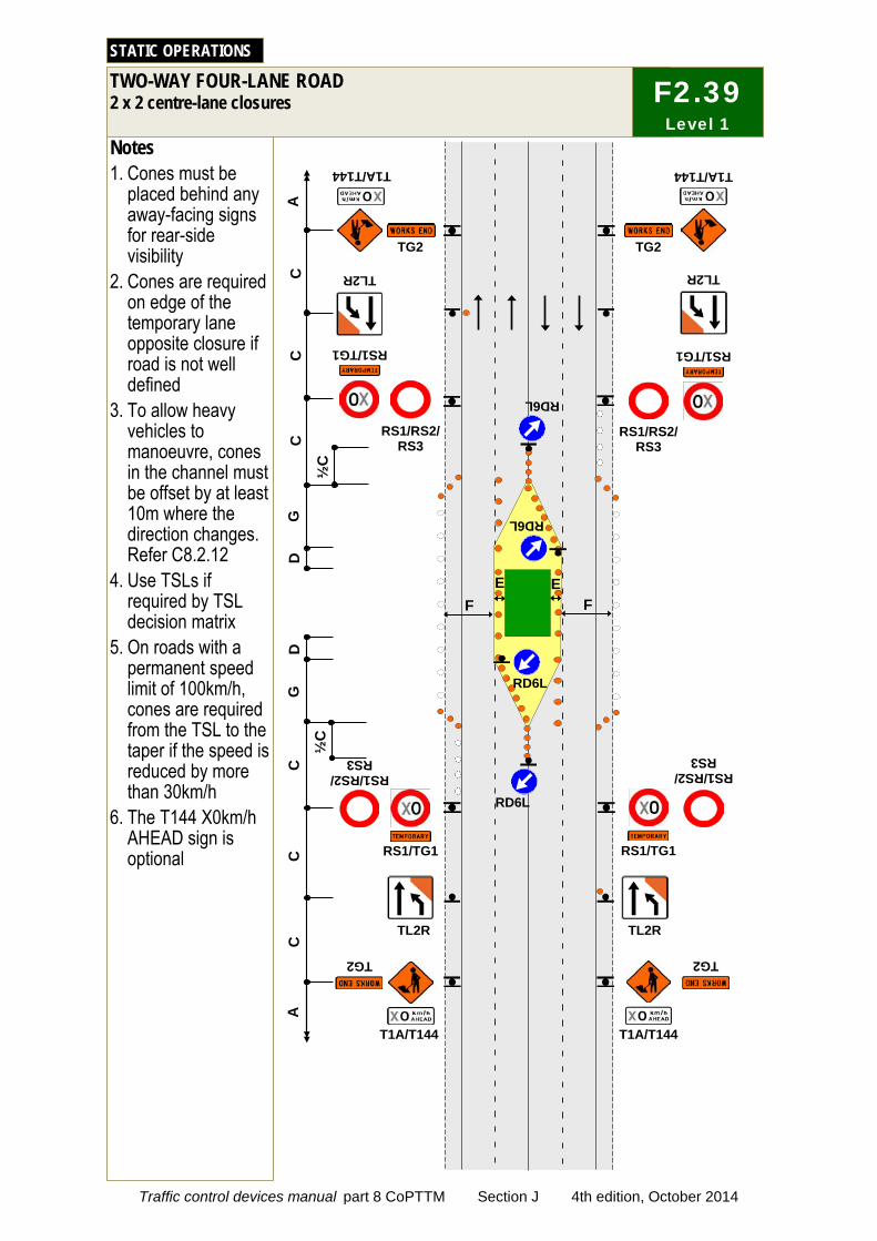
Notes 1. Cones must be
placed behind any away-facing signs for rear-side visibility
2. Cones are required on edge of the temporary lane opposite closure if road is not well defined
3. To allow heavy vehicles to manoeuvre, cones in the channel must be offset by at least 10m where the direction changes. Refer C8.2.12
4. Use TSLs if required by TSL decision matrix
5. On roads with a permanent speed limit of 100km/h, cones are required from the TSL to the taper if the speed is reduced by more than 30km/h
6. The T144 X0km/h AHEAD sign is optional
TWO-WAY FOUR-LANE ROAD 2 x 2 centre-lane closures
STATIC OPERATIONS
E
C
C
C
RS1/RS2/ RS3
TG2
T1A/T144
RS1/TG1
T1A/T144
RS1/RS2/ RS3
TG2 A
RS1/TG1
F
RS1/RS2/ RS3
RS1/TG1
RS1/RS2/ RS3
C
TG2
C
A
RS1/TG1
T1A/T144 T1A/T144
TG2
E
RD6L
D
G
D
G
C
TL2R TL2R
TL2R TL2R
RD6L
½C
RD6L
½C
RD6L
F
F2.39 Level 1
Traffic control devices manual part 8 CoPTTM Section J 4th edition, October 2014
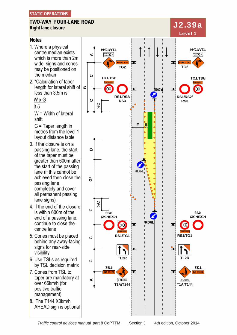
Notes 1. Where a physical
centre median exists which is more than 2m wide, signs and cones may be positioned on the median
2. *Calculation of taper length for lateral shift of less than 3.5m is: W x G 3.5 W = Width of lateral shift G = Taper length in metres from the level 1 layout distance table
3. If the closure is on a passing lane, the start of the taper must be greater than 600m after the start of the passing lane (if this cannot be achieved then close the passing lane completely and cover all permanent passing lane signs)
4. If the end of the closure is within 600m of the end of a passing lane, continue to close the centre lane
5. Cones must be placed behind any away-facing signs for rear-side visibility
6. Use TSLs as required by TSL decision matrix
7. Cones from TSL to taper are mandatory at over 65km/h (for positive traffic management)
8. The T144 X0km/h AHEAD sign is optional
TWO-WAY FOUR-LANE ROAD Right lane closure
STATIC OPERATIONS
C
C
RD6L
T1A/T144
RS1/TG1
TG2
RS1/RS2/ RS3
TG2
RS1/RS2/ RS3
T1A/T144
RS1/TG1
A
C
C
D
C
G*
RS1/RS2/ RS3
TG2
TL2R
T1A/T144
RS1/TG1 RS1/TG1
TL2R
T1A/T144
RS1/RS2/ RS3
TG2
RD6L
A
B
RD6L
F E
½C
½
C
J2.39a Level 1
Traffic control devices manual part 8 CoPTTM Section J 4th edition, October 2014
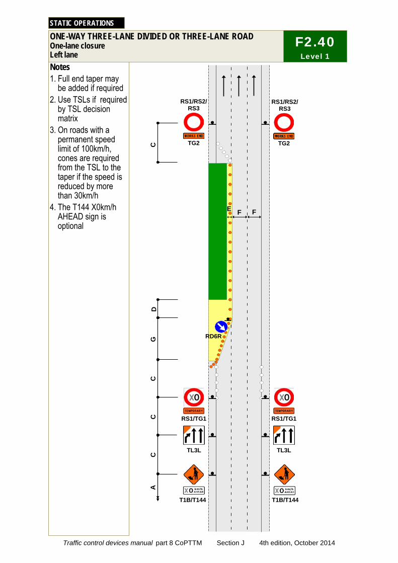
F E
RD6R
D
C
C
C
G
Notes 1. Full end taper may
be added if required 2. Use TSLs if required
by TSL decision matrix
3. On roads with a permanent speed limit of 100km/h, cones are required from the TSL to the taper if the speed is reduced by more than 30km/h
4. The T144 X0km/h AHEAD sign is optional
ONE-WAY THREE-LANE DIVIDED OR THREE-LANE ROAD One-lane closure Left lane
STATIC OPERATIONS
C TL3L
T1B/T144
A
RS1/TG1
TG2
RS1/RS2/ RS3
TG2
RS1/RS2/ RS3
T1B/T144
TL3L
RS1/TG1
F
F2.40 Level 1
Traffic control devices manual part 8 CoPTTM Section J 4th edition, October 2014

RD6R
RD6R
K
C
C
C
G
Notes 1. Cones are required
on edge of the temporary lane opposite closure if road is not well defined
2. Use TSLs if required by TSL decision matrix
3. On roads with a permanent speed limit of 100km/h, cones are required from the TSL to the taper if the speed is reduced by more than 30km/h
4. The T144 X0km/h AHEAD sign is optional
ONE-WAY THREE-LANE DIVIDED OR THREE-LANE ROAD Two-lane closure Left and centre lanes
STATIC OPERATIONS
C TL3L TL3L
D
G
TL2L TL2L
C
T1A/T144 T1A/T144
A
RS1/TG1 RS1/TG1
TG2
RS1/RS2/ RS3
TG2
RS1/RS2/ RS3
F E
F2.41 Level 1
Traffic control devices manual part 8 CoPTTM Section J 4th edition, October 2014
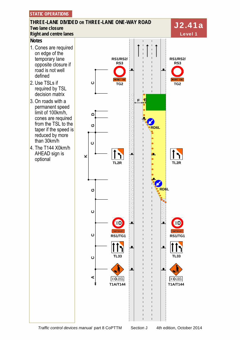
Notes 1. Cones are required
on edge of the temporary lane opposite closure if road is not well defined
2. Use TSLs if required by TSL decision matrix
3. On roads with a permanent speed limit of 100km/h, cones are required from the TSL to the taper if the speed is reduced by more than 30km/h
4. The T144 X0km/h AHEAD sign is optional
THREE-LANE DIVIDED OR THREE-LANE ONE-WAY ROAD Two lane closure Right and centre lanes
STATIC OPERATIONS
TL33 TL33
TL2R TL2R
K
C
C
C
G
C
D
G
C
T1A/T144 T1A/T144
A
RS1/TG1 RS1/TG1
TG2
RS1/RS2/ RS3
TG2
RS1/RS2/ RS3
RD6L
RD6L
F E
J2.41a Level 1
Traffic control devices manual part 8 CoPTTM Section J 4th edition, October 2014

RD6R
RD6R
Notes 1. Cones are required
on edge of the temporary lane opposite closure if road is not well defined
2. *Calculation of taper length for lateral shift of less than 3.5m is: W x G 3.5 W = Width of lateral shift G = Taper length in metres from the level 1 layout distance table
3. To allow heavy vehicles to manoeuvre, cones in the channel must be offset by at least 10m where the direction changes. Refer C8.2.12
4. Use TSLs if required by TSL decision matrix
5. On roads with a permanent speed limit of 100km/h, cones are required from the TSL to the taper if the speed is reduced by more than 30km/h
6. The T144 X0km/h AHEAD sign is optional
ONE-WAY THREE-LANE DIVIDED OR THREE-LANE ROAD Two-lane closure Two lane temporary diversion
STATIC OPERATIONS
C
C
C
K
C
D
C
G
TG2
RS1/RS2/ RS3
TG2
RS1/RS2/ RS3
T1A/T144 T1A/T144
RS1/TG1 RS1/TG1
F E F
TL5R TL5R
TL3L TL3L
A
G*
½C
G*
½C
F2.42 Level 1
Traffic control devices manual part 8 CoPTTM Section J 4th edition, October 2014
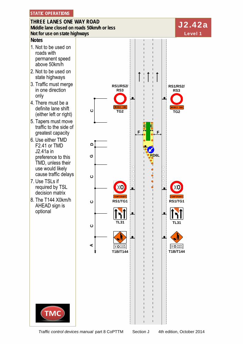
Notes 1. Not to be used on
roads with permanent speed above 50km/h
2. Not to be used on state highways
3. Traffic must merge in one direction only
4. There must be a definite lane shift (either left or right)
5. Tapers must move traffic to the side of greatest capacity
6. Use either TMD F2.41 or TMD J2.41a in preference to this TMD, unless their use would likely cause traffic delays
7. Use TSLs if required by TSL decision matrix
8. The T144 X0km/h AHEAD sign is optional
THREE LANES ONE WAY ROAD Middle lane closed on roads 50km/h or less Not for use on state highways
STATIC OPERATIONS
C
C
D
C
G
T1B/T144
RS1/TG1
T1B/T144
A
F
RS1/TG1
C
TG2
RS1/RS2/ RS3
TG2
RS1/RS2/ RS3
F E E
TL31 TL31
RD6L
J2.42a Level 1
Traffic control devices manual part 8 CoPTTM Section J 4th edition, October 2014
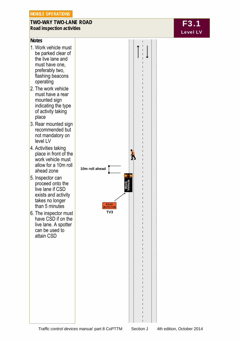
Notes 1. Work vehicle must
be parked clear of the live lane and must have one, preferably two, flashing beacons operating
2. The work vehicle must have a rear mounted sign indicating the type of activity taking place
3. Rear mounted sign recommended but not mandatory on level LV
4. Activities taking place in front of the work vehicle must allow for a 10m roll ahead zone
5. Inspector can proceed onto the live lane if CSD exists and activity takes no longer than 5 minutes
6. The inspector must have CSD if on the live lane. A spotter can be used to attain CSD
TWO-WAY TWO-LANE ROAD Road inspection activities
MOBILE OPERATIONS
F3.1 Level LV
TV3
Wor
k
Vehi
cle
10m roll ahead
Traffic control devices manual part 8 CoPTTM Section J 4th edition, October 2014

Notes 1. This TMD can be
used if the work vehicle is on shoulder, berm or live lane
2. The only signage required is a T1A sign with appropriate supplementary plate mounted on the rear of the work vehicle
TWO-WAY TWO-LANE ROAD Work vehicle is in a lane With CSD - on LV Low-risk roads (any speed) and LV roads under 65km/h
MOBILE OPERATIONS
F3.2 Level LV
T1A/T132
Rear visibility is greater than clear
sight distance
Wor
k
Vehi
cle
Traffic control devices manual part 8 CoPTTM Section J 4th edition, October 2014
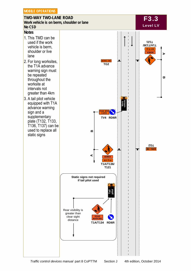
Notes 1. This TMD can be
used if the work vehicle is berm, shoulder or live lane
2. For long worksites, the T1A advance warning sign must be repeated throughout the worksite at intervals not greater than 4km
3. A tail pilot vehicle equipped with T1A advance warning sign and a supplementary plate (T132, T133, T136, T137) can be used to replace all static signs
TWO-WAY TWO-LANE ROAD Work vehicle is on berm, shoulder or lane No CSD
MOBILE OPERATIONS
F3.3 Level LV
TG2
T1A/T136/ T121
TG2
B
TV4 RD6R
NEXT X km
T1A/T136/ T121
NEXT X km
A
B
A
Wor
k ve
hicl
e
T1A/T134 RD6R
Rear visibility is greater than clear sight distance
Tail
pi
lot
Static signs not required if tail pilot used
Traffic control devices manual part 8 CoPTTM Section J 4th edition, October 2014
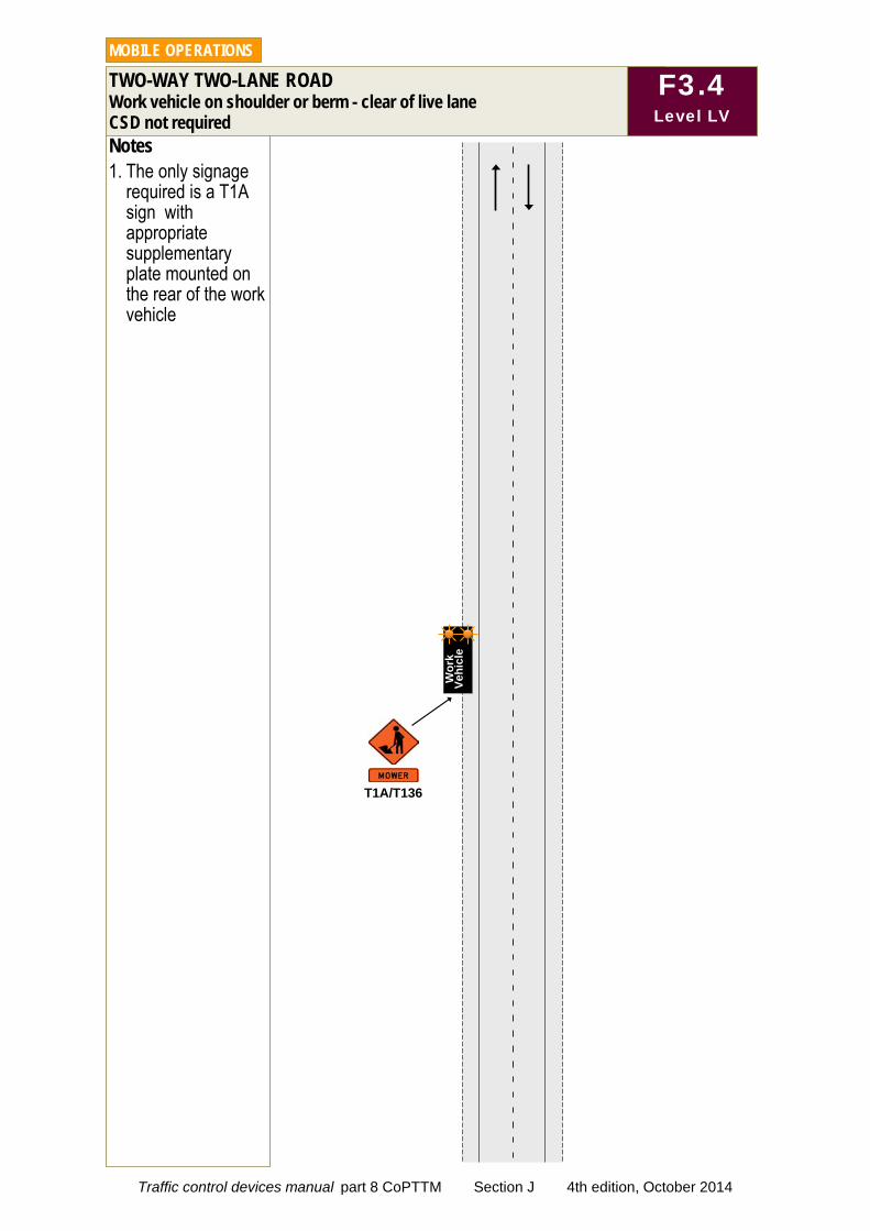
Notes 1. The only signage
required is a T1A sign with appropriate supplementary plate mounted on the rear of the work vehicle
TWO-WAY TWO-LANE ROAD Work vehicle on shoulder or berm - clear of live lane CSD not required
MOBILE OPERATIONS
F3.4 Level LV
Wor
k
Vehi
cle
T1A/T136
Traffic control devices manual part 8 CoPTTM Section J 4th edition, October 2014
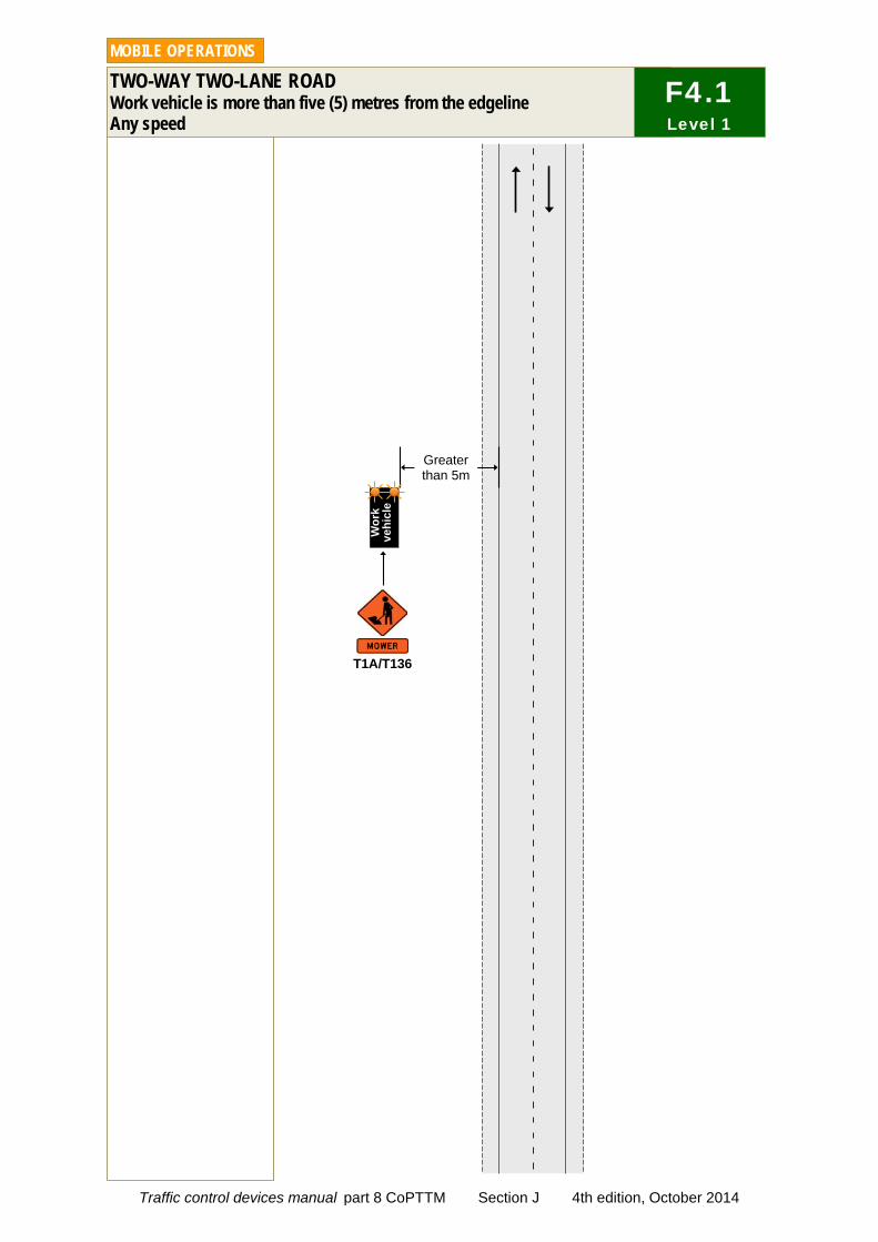
TWO-WAY TWO-LANE ROAD Work vehicle is more than five (5) metres from the edgeline Any speed
MOBILE OPERATIONS
T1A/T136
Wor
k ve
hicl
e
Greater than 5m
F4.1 Level 1
Traffic control devices manual part 8 CoPTTM Section J 4th edition, October 2014
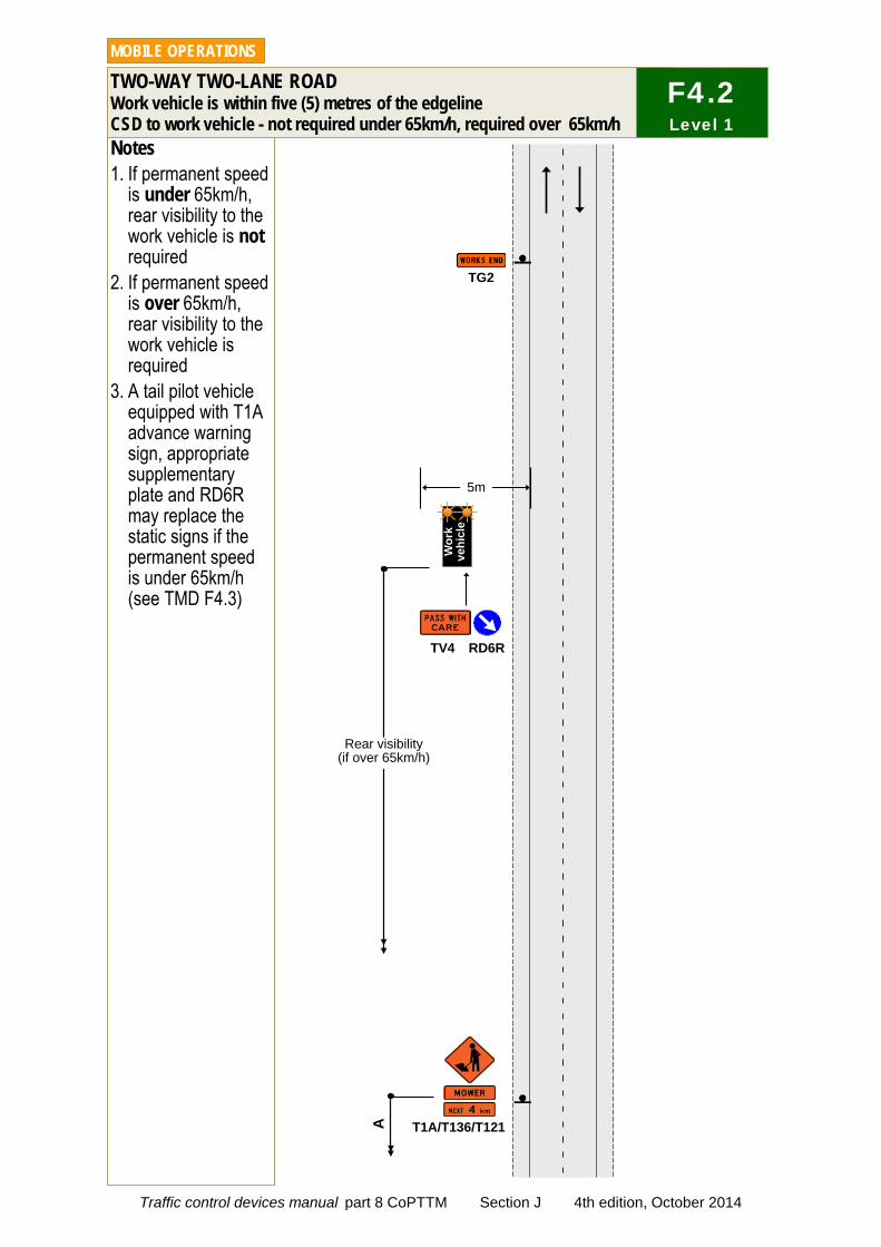
Notes 1. If permanent speed
is under 65km/h, rear visibility to the work vehicle is not required
2. If permanent speed is over 65km/h, rear visibility to the work vehicle is required
3. A tail pilot vehicle equipped with T1A advance warning sign, appropriate supplementary plate and RD6R may replace the static signs if the permanent speed is under 65km/h (see TMD F4.3)
TWO-WAY TWO-LANE ROAD Work vehicle is within five (5) metres of the edgeline CSD to work vehicle - not required under 65km/h, required over 65km/h
MOBILE OPERATIONS
T1A/T136/T121
TG2
A
TV4 RD6R
5m
Wor
k ve
hicl
e
F4.2 Level 1
Rear visibility (if over 65km/h)
Traffic control devices manual part 8 CoPTTM Section J 4th edition, October 2014
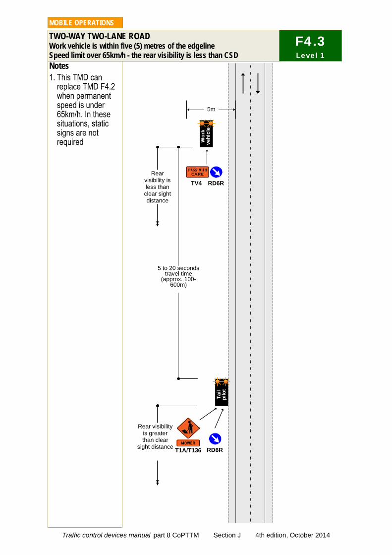
Notes 1. This TMD can
replace TMD F4.2 when permanent speed is under 65km/h. In these situations, static signs are not required
TWO-WAY TWO-LANE ROAD Work vehicle is within five (5) metres of the edgeline Speed limit over 65km/h - the rear visibility is less than CSD
MOBILE OPERATIONS
T1A/T136
5m
TV4 RD6R Rear
visibility is less than
clear sight distance
RD6R
5 to 20 seconds travel time
(approx. 100-600m)
Rear visibility is greater than clear
sight distance
Wor
k ve
hicl
e
Tail
pi
lot
F4.3 Level 1
Traffic control devices manual part 8 CoPTTM Section J 4th edition, October 2014

Notes 1. Advance warning
sign X may be replaced by tail pilot equipped with T1A advance warning sign and appropriate supplementary plate
2. In this case, signs marked with Y do not need to be erected
TWO-WAY TWO-LANE ROAD Work vehicle is in a lane Permanent speed under 65km/h
MOBILE OPERATIONS
TG2
T1A/T136/ T121
A
T1A/T121 A
TG2
TV4 RD6R
Y Y
Y X
Wor
k ve
hicl
e
F4.4 Level 1
Traffic control devices manual part 8 CoPTTM Section J 4th edition, October 2014

TWO-WAY TWO-LANE ROAD Work vehicle is in a lane Permanent speed over 65km/h - CSD forward visibility to work vehicle
MOBILE OPERATIONS
T1A/T134 RD6R
5 to 20 seconds travel time (approx. 100-600m)
Rear visibility is greater than
clear sight distance
TV4 RD6R
TV2
Forward visibility is greater than clear
sight distance
Rear visibility Ta
il p
ilot
Wor
k ve
hicl
e
F4.5 Level 1
Traffic control devices manual part 8 CoPTTM Section J 4th edition, October 2014
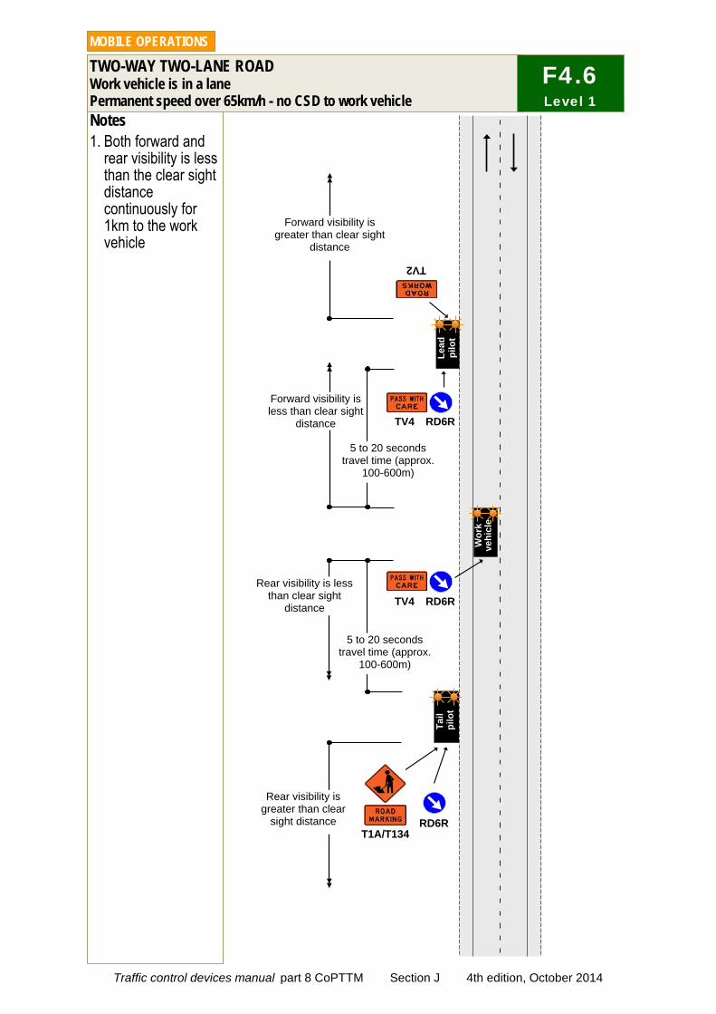
Notes 1. Both forward and
rear visibility is less than the clear sight distance continuously for 1km to the work vehicle
TWO-WAY TWO-LANE ROAD Work vehicle is in a lane Permanent speed over 65km/h - no CSD to work vehicle
MOBILE OPERATIONS
T1A/T134 RD6R
5 to 20 seconds travel time (approx.
100-600m)
Rear visibility is greater than clear
sight distance
TV4 RD6R
TV2
Forward visibility is greater than clear sight
distance
Rear visibility is less than clear sight
distance TV4 RD6R
Forward visibility is less than clear sight
distance Le
ad
pilo
t
Wor
k ve
hicl
e
Tail
pilo
t 5 to 20 seconds
travel time (approx. 100-600m)
F4.6 Level 1
Traffic control devices manual part 8 CoPTTM Section J 4th edition, October 2014
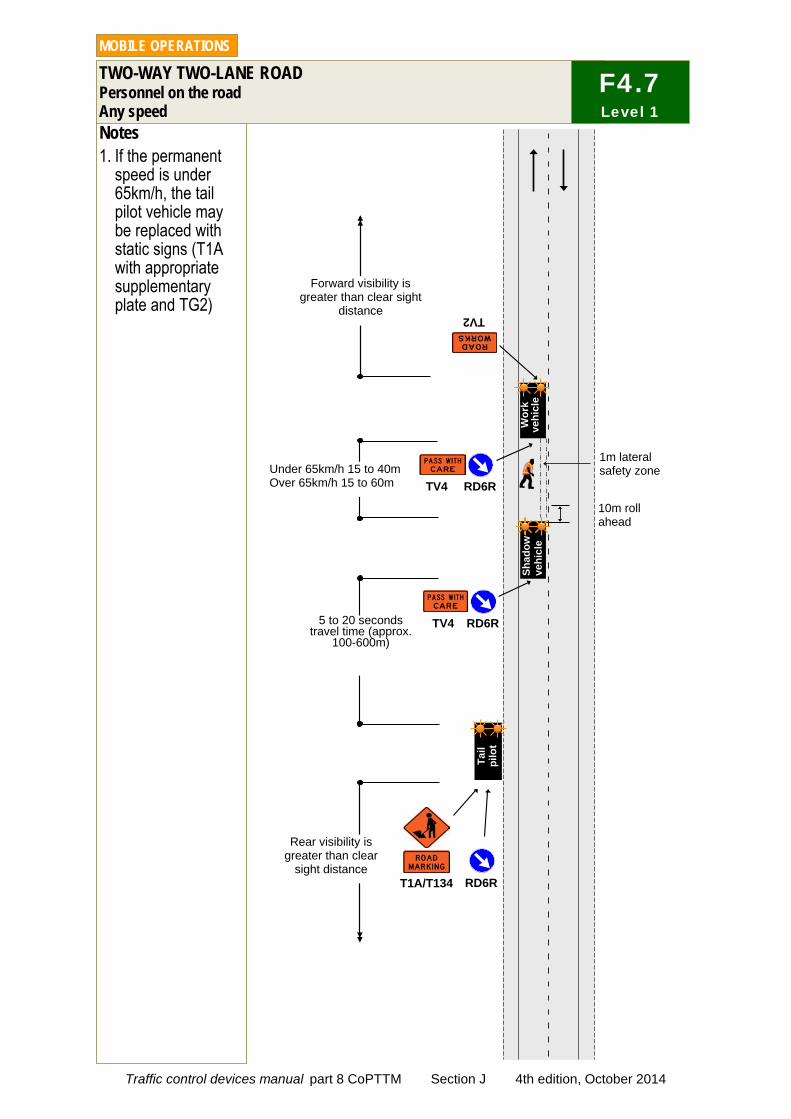
Notes 1. If the permanent
speed is under 65km/h, the tail pilot vehicle may be replaced with static signs (T1A with appropriate supplementary plate and TG2)
TWO-WAY TWO-LANE ROAD Personnel on the road Any speed
MOBILE OPERATIONS
F4.7 Level 1
5 to 20 seconds travel time (approx.
100-600m)
TV2
Forward visibility is greater than clear sight
distance
TV4 RD6R
TV4 RD6R Under 65km/h 15 to 40m Over 65km/h 15 to 60m
Wor
k ve
hicl
e Sh
adow
ve
hicl
e
T1A/T134 RD6R
Rear visibility is greater than clear
sight distance
Tail
pi
lot
1m lateral safety zone
10m roll ahead
Traffic control devices manual part 8 CoPTTM Section J 4th edition, October 2014
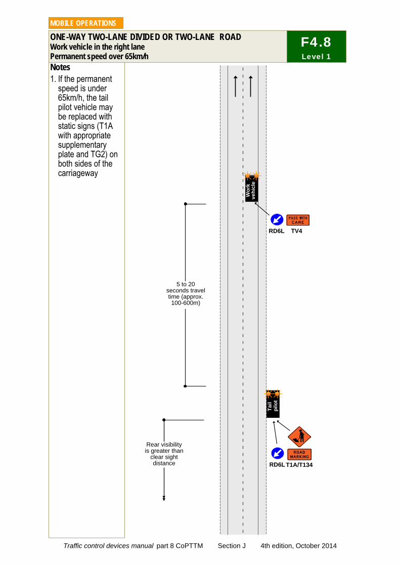
Notes 1. If the permanent
speed is under 65km/h, the tail pilot vehicle may be replaced with static signs (T1A with appropriate supplementary plate and TG2) on both sides of the carriageway
ONE-WAY TWO-LANE DIVIDED OR TWO-LANE ROAD Work vehicle in the right lane Permanent speed over 65km/h
MOBILE OPERATIONS
5 to 20 seconds travel time (approx. 100-600m)
Rear visibility is greater than
clear sight distance
TV4 RD6L
RD6L T1A/T134
Tail
pilo
t
Wor
k ve
hicl
e
F4.8 Level 1
Traffic control devices manual part 8 CoPTTM Section J 4th edition, October 2014
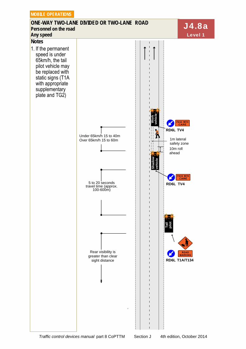
JJ
Notes 1. If the permanent
speed is under 65km/h, the tail pilot vehicle may be replaced with static signs (T1A with appropriate supplementary plate and TG2)
ONE-WAY TWO-LANE DIVIDED OR TWO-LANE ROAD Personnel on the road Any speed
MOBILE OPERATIONS
J4.8a Level 1
5 to 20 seconds travel time (approx.
100-600m)
TV4 RD6L Under 65km/h 15 to 40m Over 65km/h 15 to 60m
Wor
k ve
hicl
e Sh
adow
ve
hicl
e
T1A/T134
Rear visibility is greater than clear
sight distance
Tail
pi
lot
TV4 RD6L
RD6L
1m lateral safety zone 10m roll ahead
Traffic control devices manual part 8 CoPTTM Section J 4th edition, October 2014
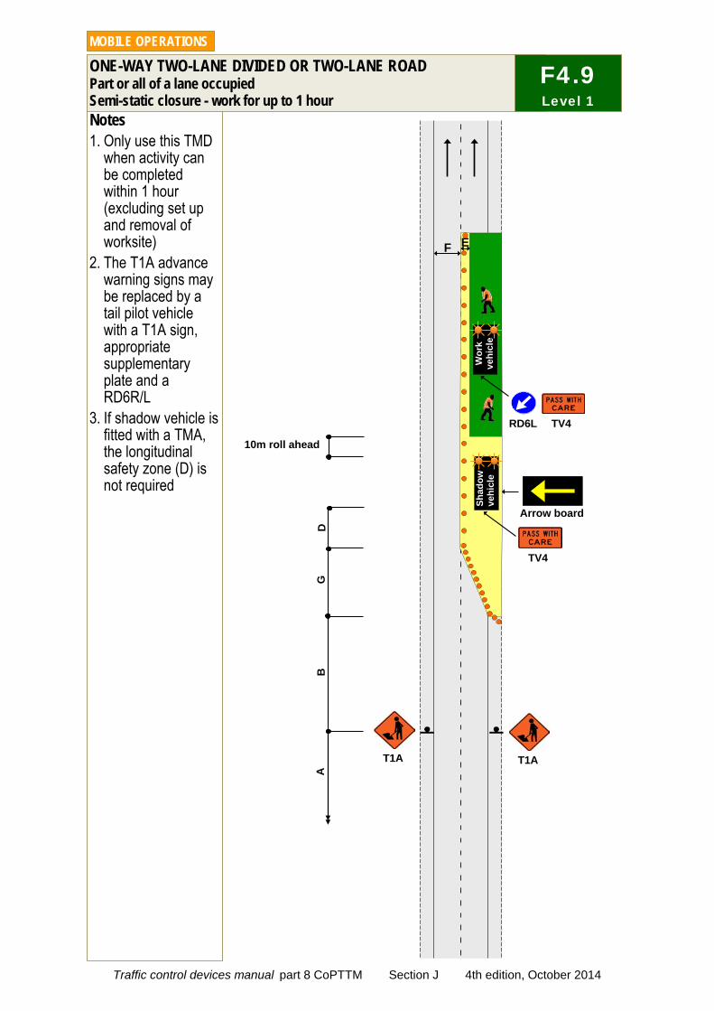
Notes 1. Only use this TMD
when activity can be completed within 1 hour (excluding set up and removal of worksite)
2. The T1A advance warning signs may be replaced by a tail pilot vehicle with a T1A sign, appropriate supplementary plate and a RD6R/L
3. If shadow vehicle is fitted with a TMA, the longitudinal safety zone (D) is not required
ONE-WAY TWO-LANE DIVIDED OR TWO-LANE ROAD Part or all of a lane occupied Semi-static closure - work for up to 1 hour
MOBILE OPERATIONS
F4.9 Level 1
T1A T1A
G
B
F E
TV4
TV4 RD6L
Arrow board
D
Wor
k ve
hicl
e
A
10m roll ahead
Shad
ow
vehi
cle
Traffic control devices manual part 8 CoPTTM Section J 4th edition, October 2014

Notes 1. Inspectors must move to avoid
traffic. They must not expect traffic to move or slow down to avoid them
2. On busy roads where traffic volumes and speed affect access to the live lane, peak periods should be avoided or a higher level of TTM considered
3. Advance warning in the form of an inspection vehicle fitted with one and preferable two amber flashing beacons and a rear-mounted sign indicating the type of activity taking place must be positioned in advance of the inspection site
4. A vehicle is not required on a level LV or level 1 road with a permanent speed of less than 65km/h if the inspector remains on a footpath
5. On roads with a permanent speed of less than 65km/h an amber flashing beacon is not required on the vehicle if the inspector or non-invasive works is on an unsealed shoulder (or further away from the carriageway - including a footpath)
6. A spotter is not required for inspections and non-invasive works on level LV roads
7. Where no LV roads have been designated, the RCA can select level 1 roads for ‘single inspector’ inspections
8. Where an unaccompanied inspector is not able to maintain adequate attention (eg due to work tasks or poor visibility), a spotter person will be required or another type of traffic management operation used
INSPECTION ACTIVITIES On shoulder and on the live lane
MOBILE OPERATIONS
TV3
Wor
k ve
hicl
e
J4.10 Level 1
I S
Spotter required when inspector on the live lane of a level 1 road (unless RCA has selected the road as suitable for ‘single inspector’ inspections)
I
No spotter required if inspector is working off the live lane
Traffic control devices manual part 8 CoPTTM Section J 4th edition, October 2014
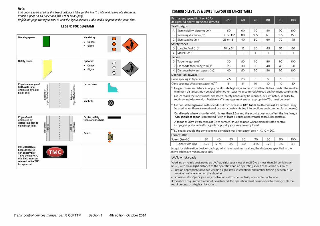
LEGEND FOR DIAGRAMS
COMBINED LEVEL LV & LEVEL 1 LAYOUT DISTANCES TABLE Note: This page is to be used as the layout distances table for the level 1 static and semi-static diagrams. Print this page on A4 paper and fold it to fit an A5 page. Unfold this page when you want to view the layout distances table and a diagram at the same time.
Traffic control devices manual part 8 CoPTTM Section J 4th edition, October 2014
NZ Transport Agency Appendices
List of appendices Appendix A TSL Decision Matrix Worksheet
Appendix B Level 1 and level LV layout distance tables
Appendix C Short TMP
Appendix D Full TMP
Appendix E Checking process GTMPs
Appendix F On-site record
Appendix G Site condition rating form – Full audit
Appendix H Site condition rating form – Short audit
Appendix I Notice of non-conformance
Appendix J Application for STMS delegated authority
These appendices are available in Word format from the CoPTTM section of the NZTA website.
Traffic control devices manual part 8 CoPTTM Section J 4th edition, October 2014
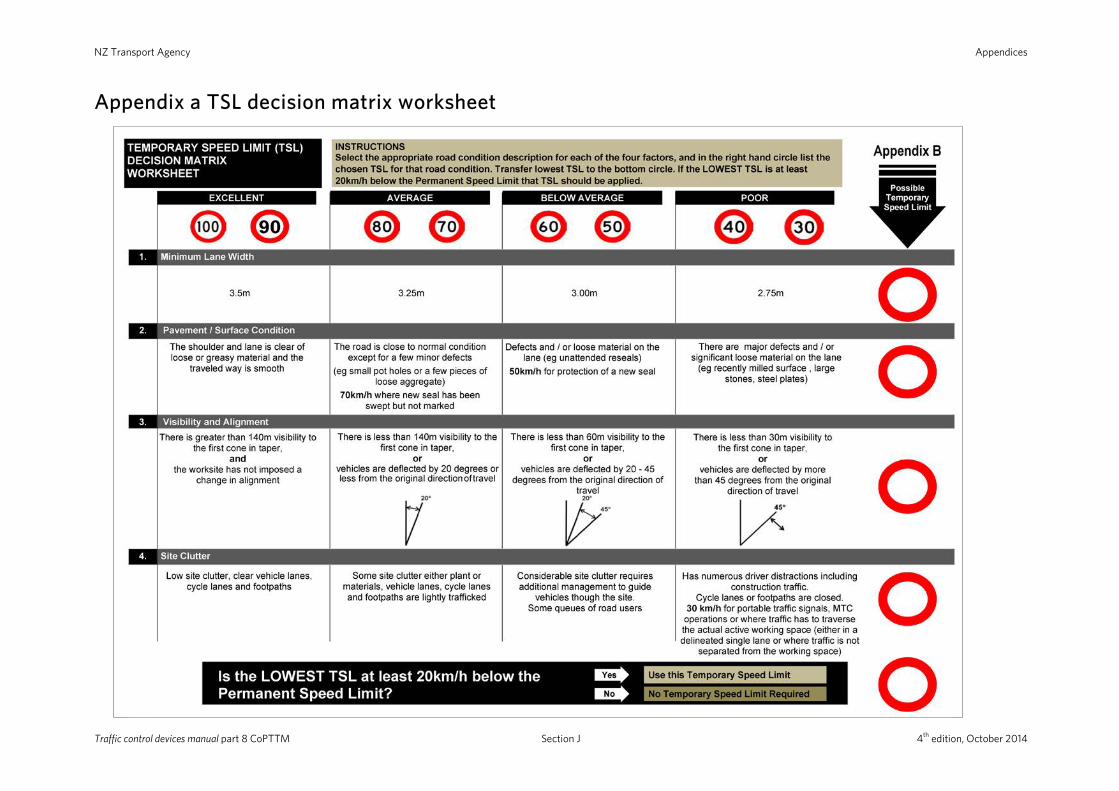
NZ Transport Agency Appendices
Appendix a TSL decision matrix worksheet
Traffic control devices manual part 8 CoPTTM Section J 4th edition, October 2014
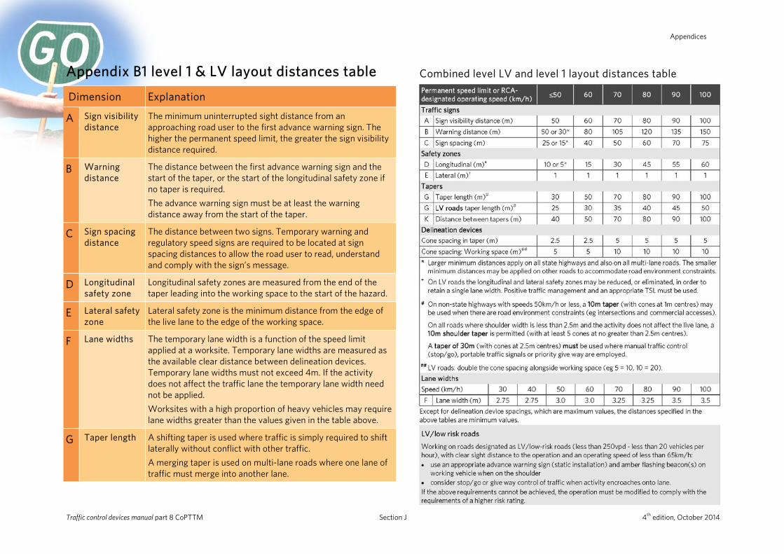
Appendices
Appendix B1 level 1 & LV layout distances table
Dimension Explanation
A
Sign visibility distance
The minimum uninterrupted sight distance from an approaching road user to the first advance warning sign. The higher the permanent speed limit, the greater the sign visibility distance required.
B Warning distance
The distance between the first advance warning sign and the start of the taper, or the start of the longitudinal safety zone if no taper is required. The advance warning sign must be at least the warning distance away from the start of the taper.
C Sign spacing distance
The distance between two signs. Temporary warning and regulatory speed signs are required to be located at sign spacing distances to allow the road user to read, understand and comply with the sign’s message.
D Longitudinal safety zone
Longitudinal safety zones are measured from the end of the taper leading into the working space to the start of the hazard.
E Lateral safety zone
Lateral safety zone is the minimum distance from the edge of the live lane to the edge of the working space.
F Lane widths The temporary lane width is a function of the speed limit applied at a worksite. Temporary lane widths are measured as the available clear distance between delineation devices. Temporary lane widths must not exceed 4m. If the activity does not affect the traffic lane the temporary lane width need not be applied. Worksites with a high proportion of heavy vehicles may require lane widths greater than the values given in the table above.
G Taper length A shifting taper is used where traffic is simply required to shift laterally without conflict with other traffic. A merging taper is used on multi-lane roads where one lane of traffic must merge into another lane.
Combined level LV and level 1 layout distances table
Traffic control devices manual part 8 CoPTTM Section J 4th edition, October 2014

NZ Transport Agency Appendices
Appendix B2 level LV layout distances table
Dimension Explanation
A Sign visibility distance
The minimum uninterrupted sight distance from an approaching road user to the first advance warning sign. The higher the permanent speed limit, the greater the sign visibility distance required.
B Warning distance
The distance between the first advance warning sign and the start of the taper, or the start of the longitudinal safety zone if no taper is required. The advance warning sign must be at least the warning distance away from the start of the taper.
C Sign spacing distance
The distance between two signs. Temporary warning and regulatory speed signs are required to be located at sign spacing distances to allow the road user to read, understand and comply with the sign’s message.
D Longitudinal safety zone
Longitudinal safety zones are measured from the end of the taper leading into the working space to the start of the hazard.
E Lateral safety zone
Lateral safety zone is the minimum distance from the edge of the live lane to the edge of the working space.
F Lane widths The temporary lane width is a function of the speed limit applied at a worksite. Temporary lane widths are measured as the available clear distance between delineation devices. Temporary lane widths must not exceed 4m. If the activity does not affect the traffic lane the temporary lane width need not be applied. Worksites with a high proportion of heavy vehicles may require lane widths greater than the values given in the table above.
G Taper length A shifting taper is used where traffic is simply required to shift laterally without conflict with other traffic. A merging taper is used on multi-lane roads where one lane of traffic must merge into another lane.
Level LV layout distances table
Traffic control devices manual part 8 CoPTTM Section J 4th edition, October 2014
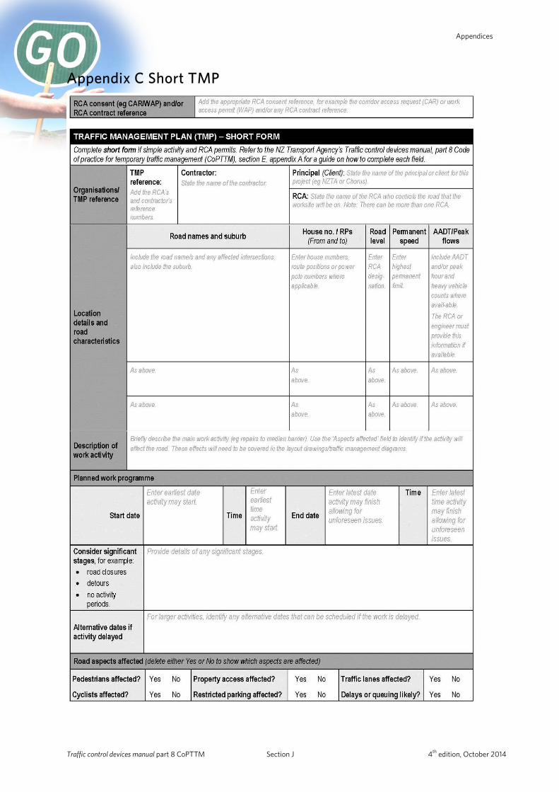
Appendices
Appendix C Short TMP
Traffic control devices manual part 8 CoPTTM Section J 4th edition, October 2014
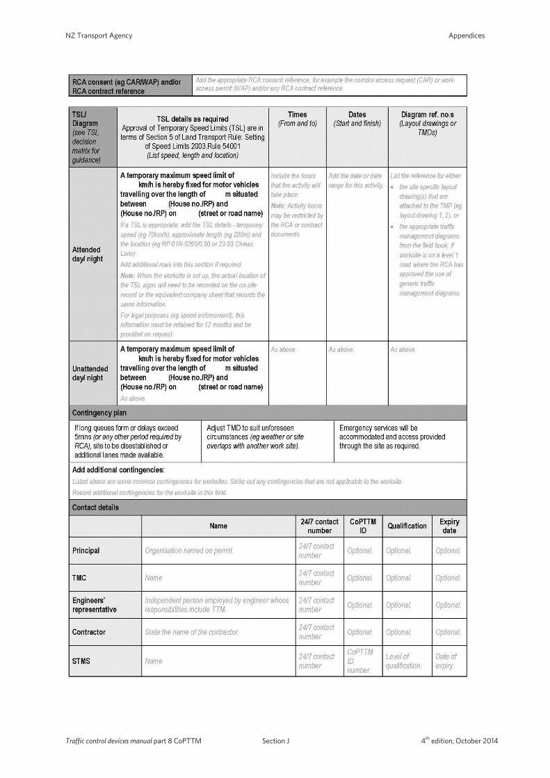
NZ Transport Agency Appendices
Traffic control devices manual part 8 CoPTTM Section J 4th edition, October 2014
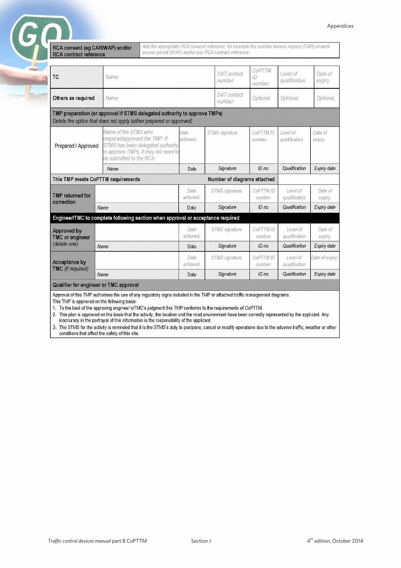
Appendices
Traffic control devices manual part 8 CoPTTM Section J 4th edition, October 2014

NZ Transport Agency Appendices
Appendix D Full TMP
Traffic control devices manual part 8 CoPTTM Section J 4th edition, October 2014
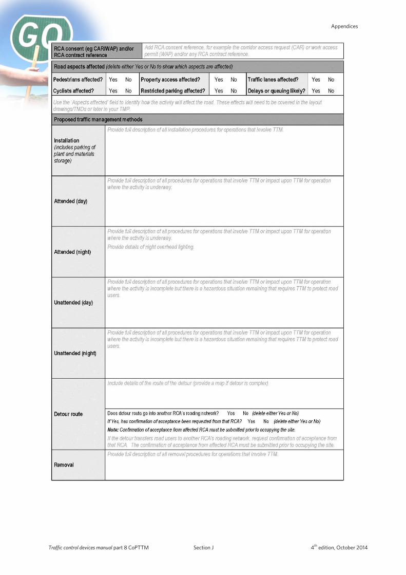
Appendices
Traffic control devices manual part 8 CoPTTM Section J 4th edition, October 2014
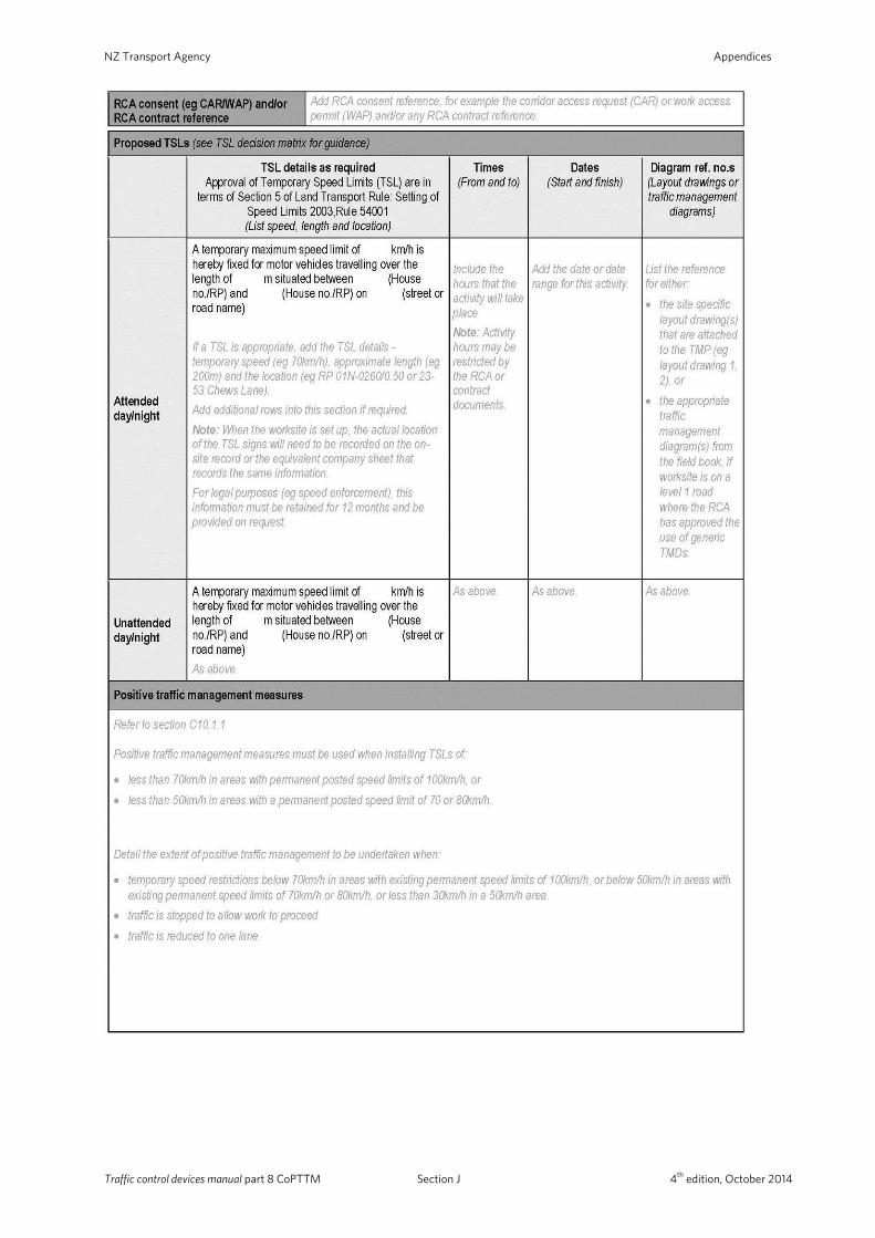
NZ Transport Agency Appendices
Traffic control devices manual part 8 CoPTTM Section J 4th edition, October 2014
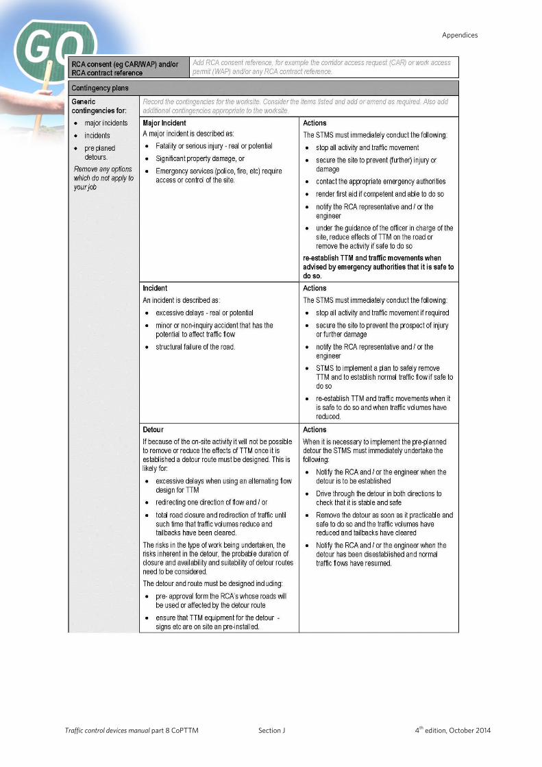
Appendices
Traffic control devices manual part 8 CoPTTM Section J 4th edition, October 2014
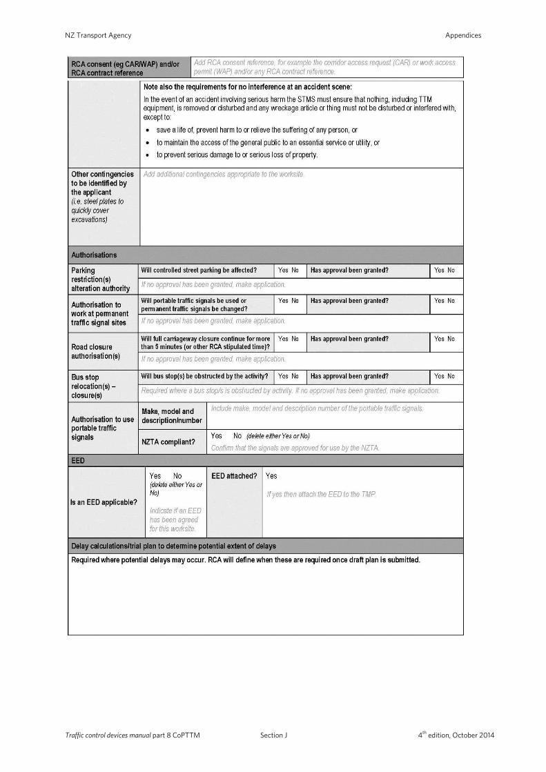
NZ Transport Agency Appendices
Traffic control devices manual part 8 CoPTTM Section J 4th edition, October 2014
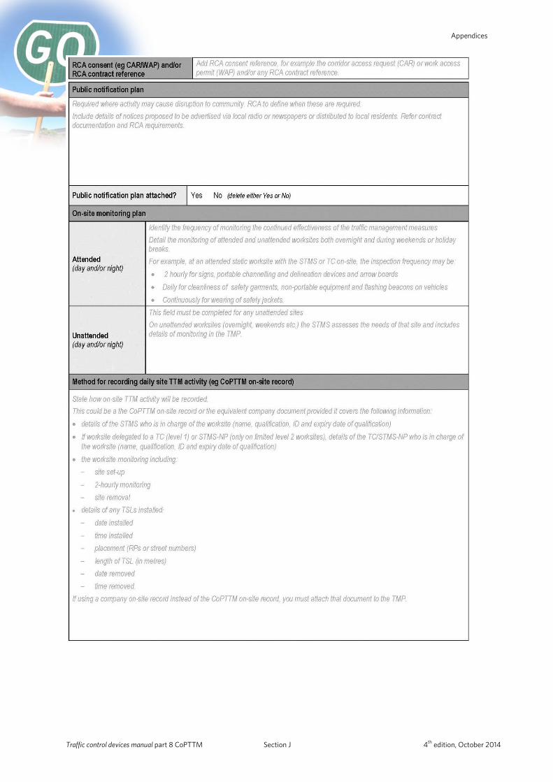
Appendices
Traffic control devices manual part 8 CoPTTM Section J 4th edition, October 2014
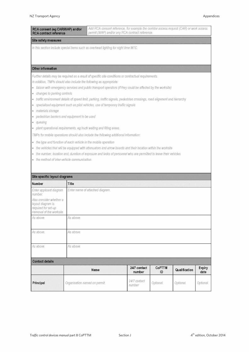
NZ Transport Agency Appendices
Traffic control devices manual part 8 CoPTTM Section J 4th edition, October 2014
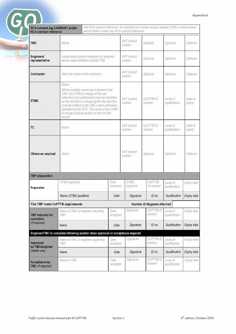
Appendices
Traffic control devices manual part 8 CoPTTM Section J 4th edition, October 2014
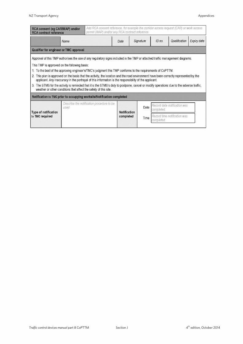
NZ Transport Agency Appendices
Traffic control devices manual part 8 CoPTTM Section J 4th edition, October 2014
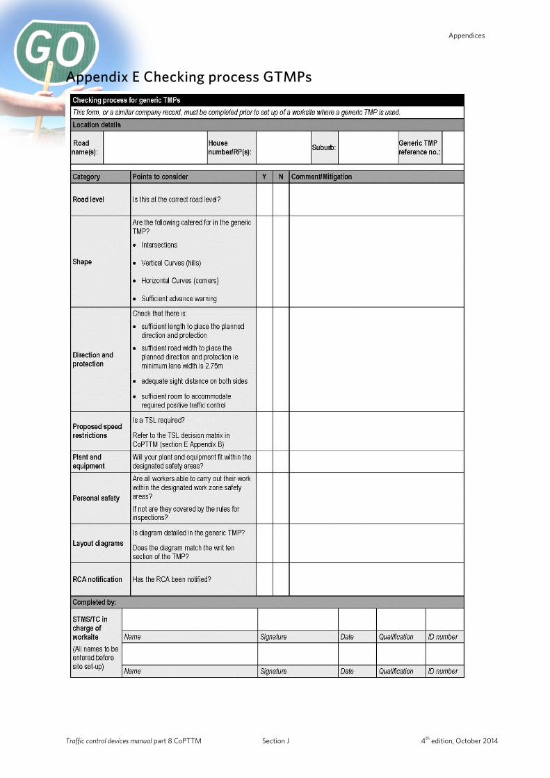
Appendices
Appendix E Checking process GTMPs
Traffic control devices manual part 8 CoPTTM Section J 4th edition, October 2014
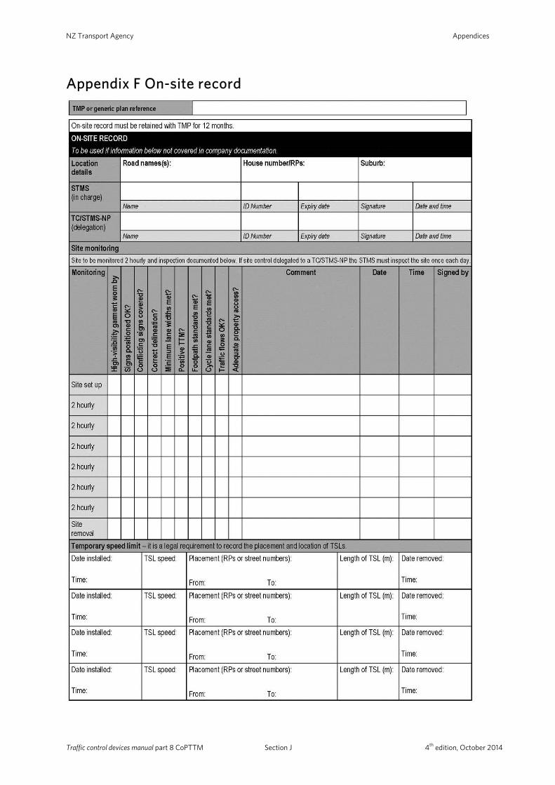
NZ Transport Agency Appendices
Appendix F On-site record
Traffic control devices manual part 8 CoPTTM Section J 4th edition, October 2014

Appendices
Appendix G Site condition rating form – Full audit
Traffic control devices manual part 8 CoPTTM Section J 4th edition, October 2014
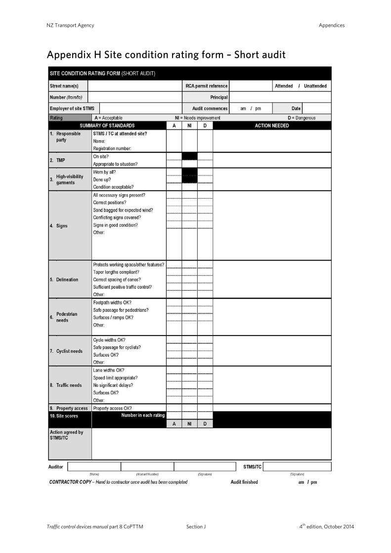
NZ Transport Agency Appendices
Appendix H Site condition rating form – Short audit
Traffic control devices manual part 8 CoPTTM Section J 4th edition, October 2014
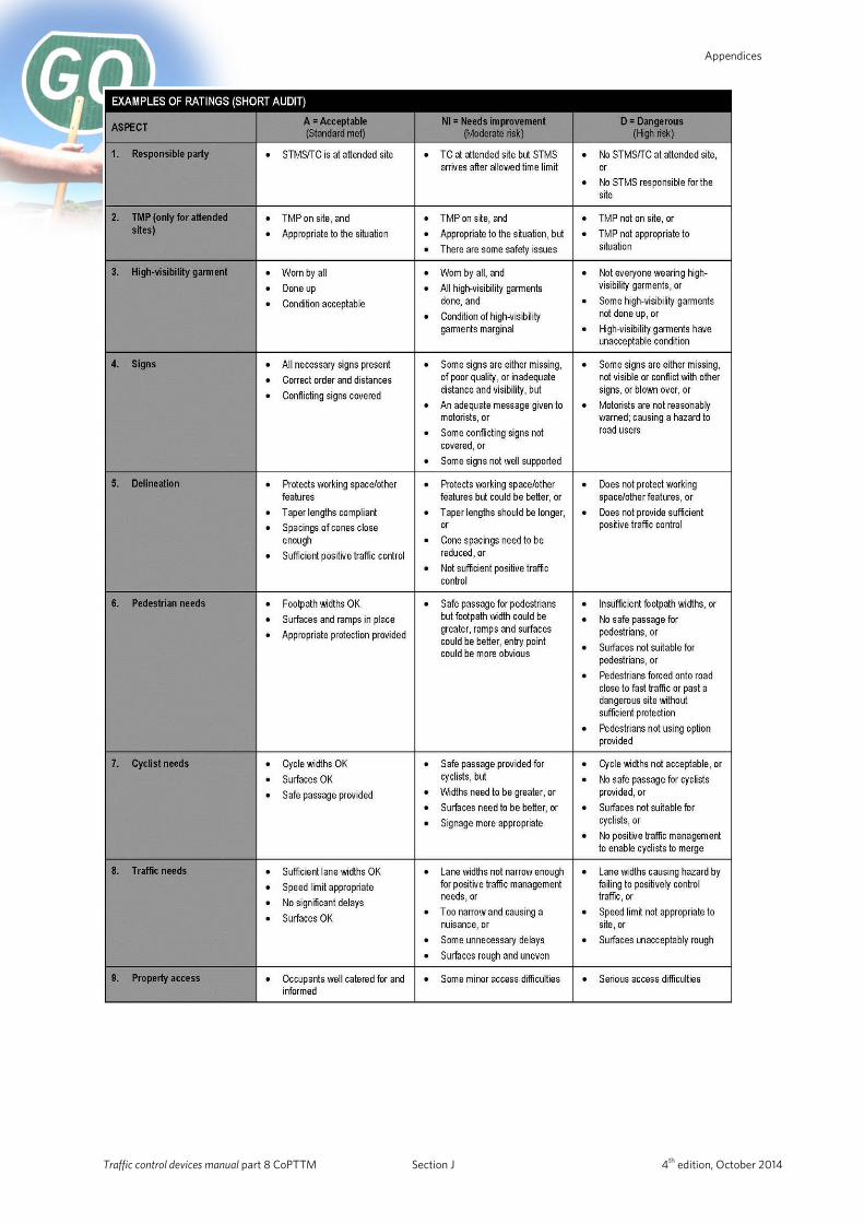
Appendices
Traffic control devices manual part 8 CoPTTM Section J 4th edition, October 2014
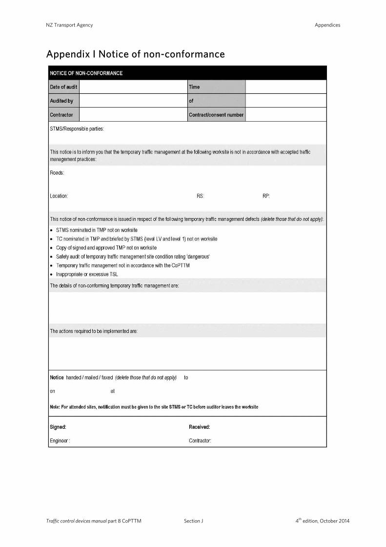
NZ Transport Agency Appendices
Appendix I Notice of non-conformance
Traffic control devices manual part 8 CoPTTM Section J 4th edition, October 2014
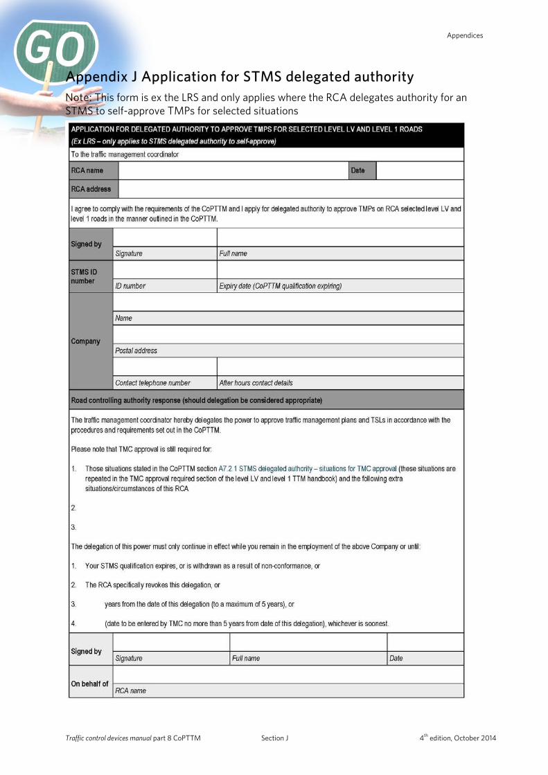
Appendices
Appendix J Application for STMS delegated authority Note: This form is ex the LRS and only applies where the RCA delegates authority for an STMS to self-approve TMPs for selected situations
Traffic control devices manual part 8 CoPTTM Section J 4th edition, October 2014