section 61: sanitary sewer system - aquatera
TRANSCRIPT

CM Section 61
Sanitary Sewer System
2018 - SECTION 61 Page 1 of 37
2018 - SECTION 61
SANITARY SEWER SYSTEM
61.1 GENERAL
The construction of all sanitary sewer mains and related sewerage structures shall be in
accordance with these specifications and all other relevant specifications.
Sewer mains shall refer to the supply and installation of pipe, manholes, bedding,
including, but not limited to the cleaning and testing of sewer pipe in accordance with
these specifications.
Sewer force mains shall refer to the supply and installation of pipe, manholes, bedding,
valves, air releases, pigg ports, including, but not limited to the cleaning and testing of
force main pipe in accordance with these specifications.
61.2 MATERIALS
61.2.1 PIPE
a) Poly vinyl Chloride (PVC) pipe
• Conforming to CSA B182.2-M1983 and ASTM D 3034.
• Standard Dimension Ratio (SDR) shall be 35. For sanitary mains in larger then
1050 mm SDR 41 may be used, subject to the written approval of Aquatera.
Approvals for SDR 41 shall be based on considerations such as depth, soil
conditions and groundwater elevations.
• Jointing shall be bell and spigot type with rubber gaskets conforming to ASTM D
3212.
b) Concrete pipe (may be used with approval from Aquatera)
• Non-reinforced concrete pipe conforming to the Standard Specification ASTM C-
14 Class III.
• Reinforced concrete pipe in accordance with ASTM C-76, or Reinforced Concrete
D-load pipe conforming to ASTM C-655.
• All concrete pipe to be manufactured with sulphate resistant (SR) cement Type V.
• Gasketed joints or confined O-rings as per ASTM C-443 requirements.
CM Section 61
Sanitary Sewer System
2018 - SECTION 61 Page 2 of 37
c) Force Main
Poly Vinyl Chloride (PVC) pipe
o Conforming to CSA B137.3 (series 160)
o Dimension Ratio (DR) shall be 26.
o Jointing shall be Bell and Spigot type with rubber gaskets conforming
to the above standards or fused as per the manufacturer’s specifications
conforming to ASTM D 2152.
o To facilitate location of force mains a tracing wire or approved
equivalent shall be placed along all forcemains at the time of
installation.
High Density Polyethylene pipe (HDPE)
o Conforming to AWWA C901 or AWWA C906
o DR11 for pipe less than 150mm
o DR 17 for pipe 150mm and larger
o Heat fusion or insert with pack joint fitting conforming to CSA B137.1
for fittings less than 100 mm and conforming to AWWA C906 for
fittings larger than 100 mm.
o Jointing of polyethylene pressure pipe greater than 100 mm shall be by
thermal butt fusion process. Procedures recommended by the pipe
manufacturer shall be followed.
o Jointing of polyethylene pressure pipe smaller than 100 mm shall be
joined with heat fusion or insert or compression fittings recommended
by the manufacture and conforming to Aquatera standards, and that
prevent pull out and resist creep deformation at full test pressure.
o To facilitate location of force mains a tracing wire or approved
equivalent shall be placed along all forcemains, low pressure sewer at
the time of installation.
Any proposed alternate materials must be approved in writing by Aquatera.
61.2.2 INSULATION FOR SANITARY SEWERS
Insulation used shall be a minimum of 50 mm thick and be composed of rigid
polyurethane foam which is formed onto the pipe. The insulation shall have a thermal
conductivity of 0.161 @ 0.174 kcal/cm/h/m2/°C and have a minimum service temperature
of -45°C. As an alternative a frost box can be installed using 50 mm foam panels as per
the Typical Detail Drawing (see 61-07).
61.2.3 MANHOLES/CHAMBERS
a) Body
Pre-cast reinforced sulphate resistant concrete barrel(s) and conical top with minimum
1200 mm inside diameter unless otherwise specified, conforming to ASTM C478.

CM Section 61
Sanitary Sewer System
2018 - SECTION 61 Page 3 of 37
Slab tops are only allowed upon prior written approval by Aquatera.
b) Bases
Bases shall be manufactured as per the Concrete Specifications with ASTM type V
(Sulphate Resistant) concrete with a minimum 28 day compressive strength of 25
MPA.
Booted connections between the manholes and pipes are not allowed within
Aquatera’s service area.
Manhole connections shall be either A Lok gaskets or approved equivalent.
c) Frame and Cover
(refer to section 300 – document - alberta specification for cast iron products) Manhole frame and cover shall be cast iron conforming to ASTM A48 Class 61. The
cover shall contain the logo "Aquatera Utilities Inc. - Sanitary Sewer" and contain
only one vent hole. The vent hole shall be 25 mm, +/- 2 mm, in diameter.
F-39 manhole covers shall be used unless specified otherwise by the municipality.
Sealed frames and covers shall be used in all ponding areas.
Floating F-80 manhole covers may be used as an alternative to the F-39, where
manholes are located in paved areas.
Floating F-90 with gasket sealed manhole covers shall be used on sanitary manholes
located in sag/ponding areas in asphalt or concrete pavement. F-90 manhole covers
shall have no vent holes.
d) Grade Rings
Grade rings shall be concrete. Bricks, shims, concrete blocks and steel riser rings and
excessive amounts of rubberneck shall not be used to adjust manhole frames and
covers.
Concrete grade rings shall be manufactured as per the Concrete Specifications with
ASTM type V (Sulphate Resistant) concrete with a minimum 28 day compressive
strength of 25 MPA.
Manholes that are located in the carriage way shall adhere to the applicable municipal
construction standards for grade rings.
e) Rungs
Manhole safety rungs shall be 20mm ∅ ribbed extruded aluminum or hot dipped
galvanized.

CM Section 61
Sanitary Sewer System
2018 - SECTION 61 Page 4 of 37
f) Concrete
All cement to be ASTM TYPE V (Sulphate resistant) 28 day strength of 25 MPa.
g) O-Ring Confined Gaskets conforming to ASTM C - 443
h) Bituminous Gasket-Type Sealant conforming to ASTM C - 990
i) Each manhole/chamber joint and grade rings shall be sealed with an external rubber
wrapping similar to the Infi-Shield Gator Wrap or Aquatera approved equivalent.
Ground conditions may require manholes to be completely wrapped.
j) Insulation
In cases where manholes are shallower than 2.75 meters, manhole bases, barrels and
cones shall be insulated with 50mm thick and be composed of rigid polyurethane foam
which is formed onto the barrels and cone. The insulation shall have a thermal
conductivity of 0.161 @ 0.174 kcal/cm/h/m2/°C and have a minimum service
temperature of -45°C. (see Manhole details).
Chambers/vaults shall be insulated regardless off depth. All chambers/vaults require a
minimum exterior insulation of 50mm (see detail 61-15 to 61-18)
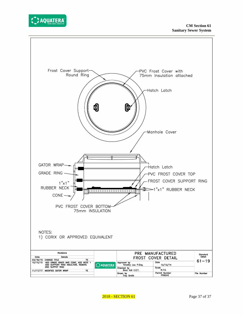
All chambers/vaults require a frost cover. Frost covers shall be pre-manufactured PVC
a minimum of 75mm or Aquatera approved equivalent.
k) Chamber Isolation Valves
All chambers shall have isolation gate valves placed outside the chambers within 2 to
3 meter of the chambers on each line. No services shall be located within 4 meters of
the chambers.
l) Pipes entering Chambers shall be a minimum of 300mm from the bottom of the pipe
and the interior chamber floor.
m) In the event of infiltration, attempts shall be made to seal leaks on exterior of
manhole via injection within the manhole/chamber using poly urethane grout.

CM Section 61
Sanitary Sewer System
2018 - SECTION 61 Page 5 of 37
61.2.4 BEDDING
a) Specified
Granular bedding (B1) shall have an even gradation falling within the following limits:
Screen Size (microns) Allowable Passing (percent)
20,000 95 to 100
12,500 75 to 95
5,000 40 to 60
2,000 25 to 45
400 10 to 25
80 2 to 10
b) Optional Granular
i) Sand
Sand bedding shall have an even gradation falling within the following limits:
Sieve Size (microns) Allowable Passing (percent)
5,000 100
2,000 70 to 95
400 30 to 65
160 10 to 25
80 2 to 10
ii) Select Native Material
Shall be well graded soil selected by the Contractor from the excavated trench
material. It shall contain no particles larger than 32 mm in its largest dimension. It
shall contain no frozen soil, roots or other objectionable material in quantities that
might cause pipe damage, excessive settlement or inadequate compaction. The
moisture content shall be such as to allow proper placing and compaction.
CM Section 61
Sanitary Sewer System
2018 - SECTION 61 Page 6 of 37
iii) Concrete
Shall be sulphate resistant, with a compressive strength of 25 MPa at 28
days, and a slump of 25-75 mm.
61.2.5 CONCRETE, GROUT, AND MORTAR
Concrete grout and mortar used for patching, filling and repairing holes, cracks and joints
in concrete manholes shall be a pre-mixed, non-shrink, cement-based patching material
consisting of sulphate resistant hydraulic cement, graded silica aggregates, special
plasticising and accelerating agents, which have been formulated for vertical or overhead
use. It shall not contain chlorides, gypsum’s, plasters, iron particles, aluminium powder,
or gas forming agents or promote the corrosion of steel it may come into contact with. Set
time shall be less than 30 minutes. One-hour compressive strength shall be a minimum of
1.5 MPa and the ultimate compressive strength shall be a minimum of 35 MPa. Bond
strengths shall be a minimum of 12 MPa." Repair material shall be applied as per
manufactures specifications. The consultant & contractor shall submit repair method to
Aquatera prior to repair.
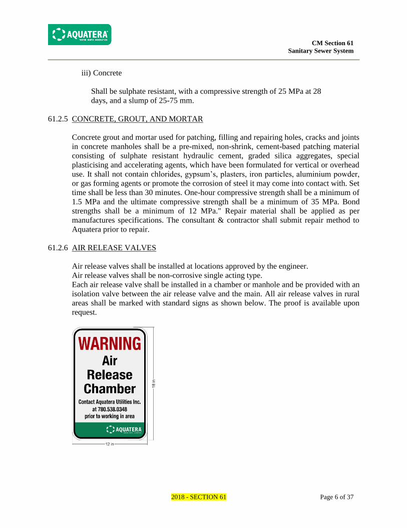
61.2.6 AIR RELEASE VALVES
Air release valves shall be installed at locations approved by the engineer.
Air release valves shall be non-corrosive single acting type.
Each air release valve shall be installed in a chamber or manhole and be provided with an
isolation valve between the air release valve and the main. All air release valves in rural
areas shall be marked with standard signs as shown below. The proof is available upon
request.

CM Section 61
Sanitary Sewer System
2018 - SECTION 61 Page 7 of 37
61.2.7 TRACER WIRE
All underground sanitary non-metallic pressure pipe systems shall be installed with a
continuous tracer wire. For open trench, tracer wire shall be a minimum 12 gauge, solid
copper wire with plastic coating, attached to the piping system every 3 m with PVC tape.
The wire shall terminate above ground at every valve box and air release valve. The wire
shall be of sufficient length to allow the wire to be uncoiled and extended 0.3 m above
ground.
For augured pipe and directional drilling, a minimum of 12 gauge copper cladded high
strength steel wire shall be used.
Where spliced-in connections occur, a manufacturer approved water-tight direct bury
connector shall be used to provide electrical continuity.
61.3 INSTALLATION
61.3.1 PIPE
a) Placement
i) All pipe laying and connecting shall be in strict accordance with the
manufacturer's recommended practice unless otherwise specified by the Engineer.
Pipe shall be laid at the depth and location shown in the Detailed Engineering
Drawings or as specified by the Engineer.
Aquatera must be notified prior to backfill if the minimum pipe depth cannot be
achieved. If 2.75m cover cannot be achieved, pre-insulated pipe shall be installed.
Alternative methods are available upon written approval from Aquatera.
(Ex. 61-07 pipe insulation frost box)
ii) The Contractor shall remove all water from the trench or tunnel prior to and during
the installation of sewer mains and sewerage structures.
All foreign material shall be kept out of the pipe before, during and after
installation. When pipe laying is not in progress the pipe shall be temporarily
plugged to prevent entry of water or other foreign material.
iii) Bell and spigot pipe shall be laid with the spigot end pointing downstream.
iv) The length of incoming pipe that cannot be bedded and supported by undisturbed
soil shall be set in an approved concrete cradle. (see Detail 61-02)

CM Section 61
Sanitary Sewer System
2018 - SECTION 61 Page 8 of 37
v) All insulated pipes shall be installed as per manufacturer's guidelines unless
otherwise directed by the Engineer.
vi) It is the Contractors responsibility to locate and protect all other utilities in the
vicinity of the work.
b) Open Cut Installation
Refers to pipe installation in an open trench. Designed trench widths must be
maintained to reflect appropriate loading on the pipe.
c) Augured Installation
Augured Installation refers to the installation of pipe into an uncased tunnel or hole.
Refer to Section 13 – Auguring of Aquatera’s Construction Specifications for detailed
requirements.
61.3.2 MANHOLES/CHAMBERS
Manholes shall be constructed in strict accordance with the manufacturers' recommended
practice unless otherwise specified in the Detailed Engineering Drawings or these
Specifications. Chambers are structures for closed systems.
Upon request the consultant shall supply Aquatera with shop drawings for unique
manholes prior to installation.
Manhole barrels showing signs of repair shall be rejected unless the repair has been
completed by the manufacturer and approved by the Engineer. The repair shall be sound,
properly finished and cured.
Manhole barrels shall be substantially free of fractures and shall be rejected for the
following:
Damage to the manhole barrel during the transportation and installation stages of
construction. The damaged manhole may be repaired as noted above
Bell and spigots that are broken for more than 5% of the external circumference
a) Placement/Body
i) The Body shall be pre cast sulphate resistant reinforced concrete. All manholes
shall be plumb with no leaning permitted.
ii) For tee-risers or perched manholes a maximum of one precast concrete manhole
riser or barrel section shall be placed on a freshly poured concrete bases and no
further work shall be done for a minimum of 12 hours allowing time for the

CM Section 61
Sanitary Sewer System
2018 - SECTION 61 Page 9 of 37
concrete base to set sufficiently.
iii) The inside manhole wall shall be finished to a smooth surface. No voids or jagged
edges of binding mortar at the joints will be permitted. Riser rings shall not be
finished with mortar unless directed by Aquatera.
iv) The joints for precast concrete manholes are to be of the confined o-ring type
conforming to ASTM C443 or current version thereof. Conical tops, flat tops and
grade rings which come without gasket are to be fully sealed to ensure the manhole
will be completely water-tight. The contractor shall use an approved flexible
bituminous gasket- type sealant. This shall be placed between all the grade rings
and between the frame and the top grade ring. The sealant between the cone and the
first grade ring and all other grade rings shall be 25mm. The joint seals shall be
installed as per manufacturer's specified guidelines. Each manhole, all grade rings
and barrel joints shall be sealed with an external rubber wrapping similar to the
Infi-Shield Gator Wrap or approved equivalent. In the event of infiltration at the
joints, all joints shall be sealed on exterior of manhole via injection within the
chamber using poly urethane grouting.
v) Stubs for future extensions shall be a minimum of 1.5m from the outside wall of
the manhole, unless otherwise directed by Aquatera. All stubs shall be plugged to
prevent the entry of water or other foreign material. The stub shall have positive
grade toward the manhole, matching the grade of the future extension of the line.
Stubs that grade toward the plug (future downstream manhole) shall be plugged at
both ends of the section of pipe installed.
vi) The incoming and outgoing pipes at a manhole shall be supported by an approved
concrete cradle of an appropriate length to properly support the pipe. The cradle
will be constructed in such a manner that will not hinder the future extension of the
main. (see Detail 61-02)
When tying into existing stubs, the Engineer and Contractor shall field verify that
the grade of the existing stub is not back graded. In the event that the stub is back
graded, the Developer will be responsible to correct the grade of the stub, before
tying into the existing stub. Any costs associated with the re-grading of a stubbed
sewer line shall be borne by the Developer.
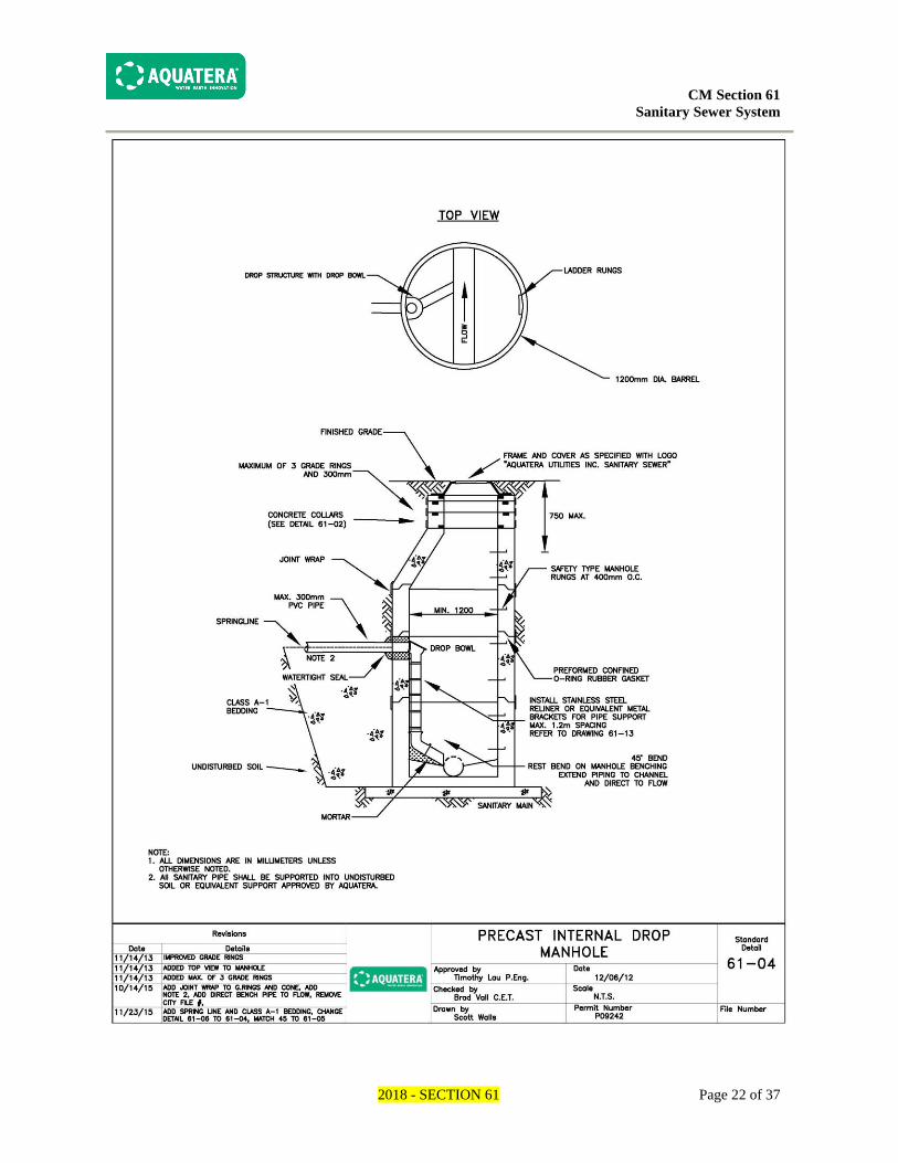
vii) Drop manholes shall be installed on all drops where the space available between
the inlet and outlet is suitable for the fittings required. If a suitable amount of space
is not available, the grade of the incoming pipe is to be increased or the entire
profile lowered to eliminate any drops. Where the inlet and outlet pipes are of
similar diameter, the desirable drop across manholes is 3 cm and 6 cm where a
change of direction occurs. Where the pipes are of dissimilar diameters, the crowns
of the pipes are to be the same elevation.
Internal drop structures shall be outfitted with Reliner inside drop components.

CM Section 61
Sanitary Sewer System
2018 - SECTION 61 Page 10 of 37
The bowl size shall be determined by incoming pipe size and flow rates. The bowl
shall be installed as per manufacturer's instructions using stainless steel fasteners.
The appropriately sized drop pipe of SDR 35 PVC shall be securely attached to the
manhole wall using stainless steel Reliner adjustable clamping brackets and
stainless steel fasteners. Bracket interval shall be 1.2m maximum (minimum of 2
brackets). The connection of drop bowl to drop pipe shall be by flexible external
pipe coupler (Fernco or approved equivalent). The turn-out at the base end of the
drop pipe shall be accomplished with an appropriately angled PVC pipe elbow (45
degree recommended).
b) Concrete Base
i) Pour in Place
The concrete base shall be poured on level undisturbed soil. The concrete base shall
have a minimum thickness of 150mm. A maximum of one barrel section shall be
placed on a freshly poured concrete base and no further work shall be done for a
minimum of 12 hours allowing time for the concrete base to set sufficiently. The
benching of the manhole outside the channel shall be smooth and slope toward the
channel with not less than 2% grade. All channels shall be trowelled smooth.
Chamber bases will have a flat surfaces with a minimum 2% grade away the side of
the ladder rungs.
ii) Precast
All bases shall be sulphate resistant reinforced concrete. The precast base shall be
set on 150 mm of compacted 20 mm gravel sub-base extending 150 mm beyond the
perimeter of the precast base. The sub-base shall be constructed on level and
undisturbed soil. The benching of the manhole outside the channel shall be smooth
and slope toward the channel with not less than 2% grade. All channels shall be
trowelled smooth.
Chamber bases will have a flat surfaces with a minimum 2% grade away the side of
the ladder rungs.
c) Frame and Cover
Frames and covers shall be installed as per the manufacturer's recommendations. The
elevation of the frame after installation shall be as per the Detailed Engineering
Drawings or as indicated by the Developer's Engineer. Where the frame elevation is
not specified, they shall be set level to the existing ground or as directed by the
Engineer. When the frame and cover are in a landscaped area there shall be positive
grade sloping away from the manhole. (see detail 61-02)
d) Ladder

CM Section 61
Sanitary Sewer System
2018 - SECTION 61 Page 11 of 37
For manholes the ladder rungs to be installed so that they align with the opening in the
conical or flat top. The first rung should be within 750 mm of the manhole cover and
continued with a 400mm O/C spacing all the way to the benching. All sharp edges on
the ladder shall be smoothed to prevent injury. Ladder rungs shall not be installed over
the inlet or outlet of the manhole wherever possible. It is preferable that where
manholes are located within roadways that the ladder rungs are positioned such that
when entering the manhole they face oncoming traffic where traffic is in one direction
on the roadway. Where the roadway has two-way traffic the ladder rungs should be
positioned perpendicular to the flow of traffic. No ladder rungs shall be installed
within the grade rings.
e) Pipe Junction
The edge formed between the intersection of the pipe and the inside of the manhole
wall shall be flush with the inside of the manhole wall and channel, and be well-
rounded and mortared to form a water tight seal. Any spaces and gaps shall be
mortared, and the top half of the pipe will be trimmed flush to the manhole wall.
Where sewer mains pass through or enter manholes, the invert channel shall be
trowelled smooth and semi-circular in cross-section. It may be formed directly in the
concrete of the manhole base, or may be constructed by laying sewer mains
continuously through the manhole, and then removing the top exposed section of pipe
after the surrounding concrete has hardened, and neatly trimming the edges.
Manhole suppliers normally offer a precast concrete base manhole with a gasket outlet
to accommodate smooth-walled Ring-Tite and Enviro-Tite PVC pipe. (IPEX
Centurion’s ODs must be specified prior to order.) The installer must simply specify
the appropriate outside diameter of the pipe to ensure a properly sized gasket will be
cast into the manhole. The Ring-Tite and Enviro-Tite pipe should be chamfered and
lubricated before insertion.
HDPE pipe is not to be used at pipe junctions through manhole/chamber walls for
pressure systems. Manhole/chambers are to have stainless steel pups (short piece of
pipe) running through manhole walls with link seals to create a water tight seal.
Grout Adapters - These fittings are manufactured from a stub of Ring-Tite, Enviro-
Tite and Centurion pipe that has been coated externally with a sand, epoxy, cement-
mortar mixture. A watertight connection can be made by placing the adapter into a
manhole outlet followed by filling the annular space around the adapter with a non-
shrink grout. The special coating is required because grout will not form a watertight
bond with the PVC.
Where the pipe enters the manhole, the pipe shall be made flush with the inside
manhole barrel and openings shall be mortared flush with the pipe and inside manhole
wall.
When placing a manhole over an existing PVC line, the existing PVC main shall be

CM Section 61
Sanitary Sewer System
2018 - SECTION 61 Page 12 of 37
adequately prepared (primed) and coated with sand, epoxy, cement mortar mixture
where connections are to be made to the concrete manhole barrel.
Grout adapter stubs shall not be manufactured on site when approved materials are
available.
f) Change of Flow Direction
Changes of direction of flow within manholes shall be made with a smooth curve
with as long a radius as possible.
g) Elevation Adjustment
A minimum of 100 mm and a maximum of 300 mm with a quantity range of 1 - 3
precast various thickness grade rings shall be used to support the manhole frame
unless otherwise specified by Aquatera. Manhole covers are to be set accurately to
grade as given in the Detailed Engineering Drawings. Where the frame and cover are
in a landscaped area there shall be positive grade away from the manhole. Where the
cover elevation is not specified, they shall be set level to the existing ground. The
minimum thickness of concrete grade ring used in the construction of manholes is
75mm.
h) Backfill
The excavated cavity surrounding the completed manhole shall be backfilled as per
the Trenching and Backfill specifications applicable to the pipe entering and/or exiting
the manhole, whichever is more stringent.
i) Link seals
When installing the link seal, the bolt heads shall be installed inside the manhole, so
they are accessible for adjustments after installation is complete.
The Link seal manufacturer shall be contacted to ensure proper sizing.
Double link seals shall be avoided.
In the event of infiltration, attempts shall be made to seal leaks on exterior of manhole
via injection within the chamber using poly urethane grout.
Link seals are not to be used on HDPE pipe through the chambers walls.
j) Pipes entering Chambers shall be a minimum of 300mm from the bottom of the pipe
and the interior chamber floor.

CM Section 61
Sanitary Sewer System
2018 - SECTION 61 Page 13 of 37
61.3.3 BEDDING
a) Placement
i) Bedding shall refer to and include all Material placed from the bottom of the trench
to 300mm above the pipe. Unless otherwise specified, bedding shall be placed by
hand up to 300 mm above the crown of the pipe. This material shall be well
tamped, in uniform 150 mm lifts, with hand tools along both sides of the pipe and
compacted to 97% Standard Proctor Density unless otherwise specified. A
minimum of 1 test per trench is required and shall be continued in 75 lineal metre
intervals, which includes sanitary mains and services. Aquatera reserves the right to
extend the maintenance period if inadequate testing is provided.
ii) No bedding shall be laid in water or frozen ground or in any condition considered
unsuitable by the Engineer.
iii) The bedding shall be shaped so as to provide a uniform and continuous support for
the pipe and fittings. Proper allowance shall be made for bells and couplings such
that the coupling does not bear directly on the bedding or support the weight of the
pipe.
iv) Where granular bedding is specified (B1), a sand approved by Aquatera may be
used as a substitute provided the pipe diameter is less than or equal to 375 mm and
the pipe has water tight joints.
v) Concrete bedding shall be placed only to the spring line of the pipe. When using
concrete bedding the contractor shall wait 12 hours prior to backfilling.
vi) Specifications for the various classes of bedding are illustrated in the Typical
Detail Drawings at the end of this Section.
61.3.4 CONNECTIONS TO EXISTING SEWER SYSTEMS
a) Construction Bulkheads
Prior to extending an existing sanitary sewer, the Contractor shall notify Aquatera 48
hours in advance and, install a watertight bulkhead or seal, in the existing sewer
immediately downstream of the point of connection, or the most practical location as
determined by Aquatera. This location is to be identified on the approved for construction
drawings. This bulkhead or seal shall remain in place until the sanitary sewer has been
cleaned of all accumulated water and debris and has been accepted by Aquatera. For
pipes up to or equal to 375 mm in diameter the contractor shall contact Aquatera at least
48 hours in advance at [email protected] or (780) 538-0348 to install a plug or seal.
For sanitary lines greater than 375 mm the contractor shall install a water tight bulkhead

CM Section 61
Sanitary Sewer System
2018 - SECTION 61 Page 14 of 37
or seal. These shall remain in place until issuance of a construction completion certificate
and/or the roadworks or other grading work has been completed. After issuance of a CCC
Aquatera will remove the plug or seal, or the contractor will be notified to remove the
bulkhead.
During all work stoppages in construction of the sanitary sewer, the open face of the last
pipe installed shall be plugged with a watertight seal to prevent sand, water, earth, or
other materials from entering the pipe.
b) Tie-In to Existing System
The work under this item shall consist of removing existing plugs and making the
connection as required to existing pipes or manhole stubs and shall include all
trenching, bedding, laying and jointing of pipe, fittings, adapters, backfilling and
clean- up, and other items necessary to complete the work as specified. Any damages
during this work shall be repaired to the satisfaction of Aquatera.
c) Break-in to Existing Sewer Main or Manhole
The work under this item shall consist of breaking into existing manholes or sewer
mains and connecting the new sewerage structure to the existing manhole or main.
Break-in shall include all trenching, bedding, laying and jointing of pipe, fittings,
adapters, backfilling and clean-up, and other items necessary to complete the work as
specified. Any damages during this work shall be repaired to the satisfaction of
Aquatera.
61.3.5 CROSSING OTHER PIPELINES OR UTILITIES
Where the sewer main being installed crosses another pipeline or utility, the minimum
clearance shall be 500 mm. The void between the two lines shall be completely filled
with a minimum of 500 mm of granular or sand material compacted to 97% Standard
Proctor unless otherwise approved by Aquatera. When crossing under an existing AC
water main, a section of that water main (minimum 4m) shall be removed and replaced
with PVC.
When crossing water mains, water services, sanitary sewer mains and sanitary sewer
service lines by Auguring refer to Section 13 of Aquatera’s Construction Manual.
61.3.6 CLEANING
The Contractor shall clean all sewerage structures of sand, dirt, gravel, asphalt and other
debris, and shall flush them clean before the maintenance period begins.

CM Section 61
Sanitary Sewer System
2018 - SECTION 61 Page 15 of 37
61.3.7 OFFSITE MARKER POSTS
Steel marker posts shall be required on all sanitary appurtenances located off site. The
marker post shall be a 63mm diameter x 2600mm steel post painted green and embedded
between 900mm and 1200mm below finished ground level. The marker post shall be
installed 1m away from the sanitary appurtenance.
61.4 TESTING REQUIREMENTS OF THE CONTRACTOR
61.4.1 PRE-INSTALLATION
a) Materials
If pipe loading is within 10% of recommended pipe strength capacity and/or the soil
conditions are highly variable in terms of moisture content, making design trench
width difficult to maintain; Aquatera may require additional pipe loading calculations
which take into consideration the trench width.
The contractor shall be responsible to inspect all materials delivered to site for
condition, damage, roundness of pipes and conformance with these standards.
b) System
The Contractor shall undertake whatever testing is necessary to safeguard and protect
existing utilities and structures.
61.4.2 INSTALLATION
a) Materials
The Contractor shall, upon request by Aquatera, provide documentation that material
being delivered to or constructed at the site is consistent with the material specified.
b) System
No testing required.
61.4.3 POST INSTALLATION
a) Material
No testing required.

CM Section 61
Sanitary Sewer System
2018 - SECTION 61 Page 16 of 37
b) Deflection Testing
Deflection testing may be required by Aquatera either during construction and/or
following construction. This may be done on any section of installed sewer main prior
to final acceptance. The allowable deflection in PVC pipe is 7.5% of the base diameter
as measured not less than 30 days following completion of construction. The base
diameter is to be calculated in accordance with ASTM D3034.
c) Closed Circuit Television Inspection
All sewer mains shall be tested in accordance to Section 25 (Closed Circuit Television
Inspection of Sewer lines)
d) Leakage (make up water) Test
Where deemed necessary by Aquatera, an exfiltration and/or infiltration test shall be
conducted. These tests shall not be required if video inspections are done immediately
after sewer construction and no deficiencies are observed. Any deficiencies shall be
corrected by the Contractor and those portions of sewer affected shall be subject to an
additional video inspection.
Infiltration or exfiltration shall not exceed following limits in litres per hour per 100m
of pipe, including service connections. (see section 300 external documents - IPEX
part 33 – PVC sewer pipe installation guide - Infiltration & Exfiltration testing)
e) Pressure Testing
Pressure testing of HDPE forcemains shall be in accordance with the latest version of
ASTM F2164. The test pressure shall be 1.0 times the rating of the pipe, but not to
exceed the pressure rating of the lowest rated component in the test section, unless
these components can be isolated. An Aquatera representative shall be contacted to
schedule to witness the test. When testing to a pressure lower than 1.0 times the pipe
rating, the specifications for the lowest rated component shall be provided with the
test results.
Pressure testing of PVC forcemains shall be in accordance with Section 91.4.3 b) of
the Aquatera Construction Manual.
The contractor shall supply all necessary labour, materials, equipment, tools and
incidentals to complete the tests in accordance with these specifications.
f) Tracer Wire
The contractor/consultant shall provide a tracer wire report to Aquatera confirming
lines were able to be located with locating equipment. (see form in section 91)
Tracer wire installation shall be considered complete and acceptable when Aquatera
can locate the underground infrastructure using locating equipment.

CM Section 61
Sanitary Sewer System
2018 - SECTION 61 Page 17 of 37
61.5 PAYMENT
61.5.1 PIPE
Payment for sanitary sewer mains shall be at the unit prices per lineal metre (L.M.) of
pipe, including couplers, shown in the Tender for the various pipe sizes and bedding
classes. Measurement shall be made along a straight line between centre line of the
upstream manhole and centre line of the downstream manhole.
61.5.2 MANHOLES (Including drop-manholes)
Payment for manholes shall be at the unit price per vertical meter (V.M.) shown in the
Tender Form measured to the nearest centimetre. The measurement for payment will be
from the lowest invert to the top of the manhole frame. The items included shall be the
supply of all materials, the construction of the complete manholes, including base, stubs
and plugs, steps, frame and cover, excavation, backfill and clean-up, and all incidentals
necessary to complete the work in accordance with these specifications.
61.5.3 BEDDING
Bedding is considered incidental to pipe installation, and unless specified otherwise, shall
be included in the pipe unit price.
61.5.4 CONNECTIONS TO EXISTING SEWER SYSTEMS
Payment for tying into an existing system will be at the unit price per tie shown in the
Tender Form. Such payment will be full compensation for all materials, fittings, adapters,
labour, equipment, supervision and all work incidentals necessary to complete the work
in accordance with these specifications.
61.5.5 CROSSING OTHER PIPELINES OR UTILITIES
Payment for crossing other pipelines or utilities will be at the unit price shown in the
Tender Form. Such payment will be full compensation for all materials, fittings, adapters,
labour, equipment, supervision and all work incidentals necessary to complete the work
in accordance with these specifications.
61.5.6 CLEANING
Cleaning is considered incidental to the Work. There shall be no separate payment for
cleaning.

CM Section 61
Sanitary Sewer System
2018 - SECTION 61 Page 18 of 37
61.5.7 TESTING REQUIREMENTS OF THE CONTRACTOR
a) Video Inspection
Video inspection of sewers shall be measured in lineal metres (L.M.) from the centre
to centre of manholes. Payment for television inspection of sewers shall be at the
tender price. Only one payment will be made and any subsequent inspections required
by Aquatera will be at the Contractor's cost.
b) Other Testing
There shall be no payment for any other testing required to be undertaken by the
Contractor.

CM Section 61
Sanitary Sewer System
2018 - SECTION 61 Page 19 of 37

CM Section 61
Sanitary Sewer System
2018 - SECTION 61 Page 20 of 37

CM Section 61
Sanitary Sewer System
2018 - SECTION 61 Page 21 of 37
CM Section 61
Sanitary Sewer System
2018 - SECTION 61 Page 22 of 37

CM Section 61
Sanitary Sewer System
2018 - SECTION 61 Page 23 of 37

CM Section 61
Sanitary Sewer System
2018 - SECTION 61 Page 24 of 37

CM Section 61
Sanitary Sewer System
2018 - SECTION 61 Page 25 of 37

CM Section 61
Sanitary Sewer System
2018 - SECTION 61 Page 26 of 37

CM Section 61
Sanitary Sewer System
2018 - SECTION 61 Page 27 of 37

CM Section 61
Sanitary Sewer System
2018 - SECTION 61 Page 28 of 37

CM Section 61
Sanitary Sewer System
2018 - SECTION 61 Page 29 of 37

CM Section 61
Sanitary Sewer System
2018 - SECTION 61 Page 30 of 37

CM Section 61
Sanitary Sewer System
2018 - SECTION 61 Page 31 of 37

CM Section 61
Sanitary Sewer System
2018 - SECTION 61 Page 32 of 37

CM Section 61
Sanitary Sewer System
2018 - SECTION 61 Page 33 of 37

CM Section 61
Sanitary Sewer System
2018 - SECTION 61 Page 34 of 37

CM Section 61
Sanitary Sewer System
2018 - SECTION 61 Page 35 of 37

CM Section 61
Sanitary Sewer System
2018 - SECTION 61 Page 36 of 37
CM Section 61
Sanitary Sewer System
2018 - SECTION 61 Page 37 of 37