section 6 weight and balance / equipment list · found section 6 fba-2c3 weight &...
TRANSCRIPT
FOUND SECTION 6 FBA-2C3 WEIGHT & BALANCE/EQUIPMENT LIST
ISSUE 2 REV 1 March 14, 2013 6 - 1
SECTION 6 WEIGHT AND BALANCE /
EQUIPMENT LIST TABLE OF CONTENTS Page Introduction .....................................................................................
6-3
Airplane Weighing Procedures ........................................................ 6-4 Airplane Weighing Form ............................................................ 6-5
Weight and Balance ......................................................................... 6-7 Sample Weight and Balance Record ........................................... 6-7 Loading Instructions ........................................................................ 6-8 Basic Loading Configuration ........................................................... 6-9 Aft Seats ...................................................................................... 6-10 Weight & Balance Loading Form ............................................... 6-11 Loading Graph ............................................................................. 6-12 Center of Gravity Moment Envelope .......................................... 6-13 Center of Gravity Range Envelope .............................................. 6-14 Carriage of Cargo ............................................................................ 6-15 Cargo Tie-Down .......................................................................... 6-15 Passenger Compartment (Cargo Tie-Down) ............................... 6-17 Baggage Compartment (Cargo Tie-Down) ................................. 6-21 Cabin Height Measurements ............................................................ 6-24 Door Opening Dimensions .............................................................. 6-25 Cabin Width Measurements ............................................................. 6-26 Comprehensive Equipment List ....................................................... 6-27
SECTION 6 FOUND WEIGHT & BALANCE/EQUIPMENT LIST FBA-2C3
6 - 2 ISSUE 2 February 12, 2012
INTENTIONALLY LEFT BLANK
FOUND SECTION 6 FBA-2C3 WEIGHT & BALANCE/EQUIPMENT LIST
ISSUE 2 February 12, 2012 6 - 3
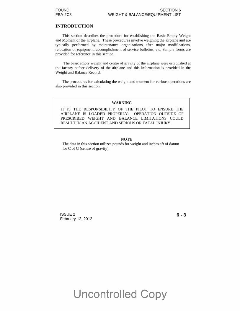
INTRODUCTION
This section describes the procedure for establishing the Basic Empty Weight
and Moment of the airplane. These procedures involve weighing the airplane and are typically performed by maintenance organizations after major modifications, relocation of equipment, accomplishment of service bulletins, etc. Sample forms are provided for reference in this section.
The basic empty weight and centre of gravity of the airplane were established at
the factory before delivery of the airplane and this information is provided in the Weight and Balance Record.
The procedures for calculating the weight and moment for various operations are
also provided in this section.
NOTE The data in this section utilizes pounds for weight and inches aft of datum for C of G (centre of gravity).
WARNING
IT IS THE RESPONSIBILITY OF THE PILOT TO ENSURE THE AIRPLANE IS LOADED PROPERLY. OPERATION OUTSIDE OF PRESCRIBED WEIGHT AND BALANCE LIMITATIONS COULD RESULT IN AN ACCIDENT AND SERIOUS OR FATAL INJURY.

SECTION 6 FOUND WEIGHT & BALANCE/EQUIPMENT LIST FBA-2C3
6 - 4 ISSUE 2 February 12, 2012
AIRPLANE WEIGHING PROCEDURES 1. Preparation:
a) Inflate tires to recommended operating pressures. b) De-fuel airplane. Refer to FAC2-M200 Maintenance Manual. c) Service engine oil as required to obtain a normal full indication. d) Move sliding seats to the most forward position. e) Raise flaps to the fully retracted position. f) Place all control surfaces in neutral position. g) Remove all non-required items from airplane.
2. Levelling:
a) Place scales under each wheel (minimum scale capacity, 1000 pounds each main, 500 pounds nose wheel).
b) Deflate the main wheel and/or lower or raise the nose wheel to properly centre the bubble in the level longitudinally and laterally (See Figure 6-1).
3. Weighing:
a) With the airplane level and brakes released, record the weight shown on each scale. Deduct the tare, if any, from each reading.
4. Measuring:
a) Obtain measurement A in Figure 6-1 by measuring horizontally and parallel to the airplane centre line, from centre of nose wheel axle, left side, to a plumb bob dropped from the line between the main wheel centres. Repeat on right side and average the measurements.
5. Calculate C.G. and Weight:
a) Using weights from Item 3 and measurements from Item 4, the airplane Basic Empty Weight and C.G. can be determined by completing the table in Figure 6-1.
b) Transfer the basic empty weight and moment data from the table in Figure
6-1 to the Weight and Balance Record, a sample of which is shown in Figure 6-2.

FOUND SECTION 6 FBA-2C3 WEIGHT & BALANCE/EQUIPMENT LIST
ISSUE 2 February 12, 2012 6 - 5
AIRPLANE WEIGHING FORM
Figure 6-1 Airplane Weighing Form (Sheet 1 of 2)
MEASURE “A” Measure “A” per item 4 of this
Section, to assist in locating CG with airplane weighed on
landing gear
LEVELING PROVISIONS Longitudinal & Lateral: Floor of the Passenger Compartment
100
50
-50
0
-100
-100 -50 0 50 100 150 200 250
REFERENCE DATUM:1/2 in AFT FROM TOP OF
LWR HINGE PIN(FRONT DOOR)
STN 0.0
IT IS THE RESPONSIBILITY OF THE PILOT TO ENSURE THAT THE
AIRPLANE IS PROPERLY LOADED
FUSELAGE STATION (FS) - INCHES
WA
TE
RLI
NE
(W
L)
- IN
CH
ES
SECTION 6 FOUND WEIGHT & BALANCE/EQUIPMENT LIST FBA-2C3
6 - 6 ISSUE 2 February 12, 2012
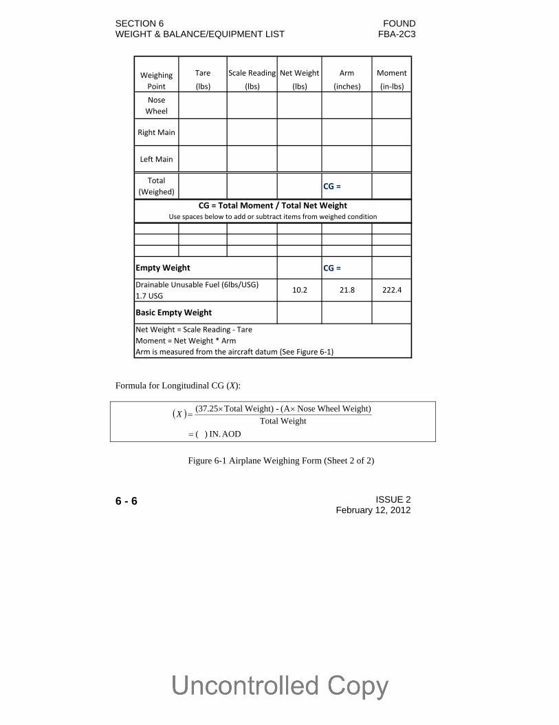
Formula for Longitudinal CG (X):
AOD IN. ) (
WeightTotal
Weight) WheelNoseA(- Weight)Total(37.25
X
Figure 6-1 Airplane Weighing Form (Sheet 2 of 2)
Tare Scale Reading Net Weight Arm Moment
(lbs) (lbs) (lbs) (inches) (in‐lbs)
Nose
Wheel
Right Main
Left Main
Total
(Weighed)CG =
CG =
1.7 USG
Basic Empty Weight
Net Weight = Scale Reading ‐ Tare
Moment = Net Weight * Arm
Arm is measured from the aircraft datum (See Figure 6‐1)
Weighing
Point
CG = Total Moment / Total Net WeightUse spaces below to add or subtract items from weighed condition
Empty Weight
Drainable Unusable Fuel (6lbs/USG)10.2 21.8 222.4
FOUND SECTION 6 FBA-2C3 WEIGHT & BALANCE/EQUIPMENT LIST
ISSUE 2 February 12, 2012 6 - 7
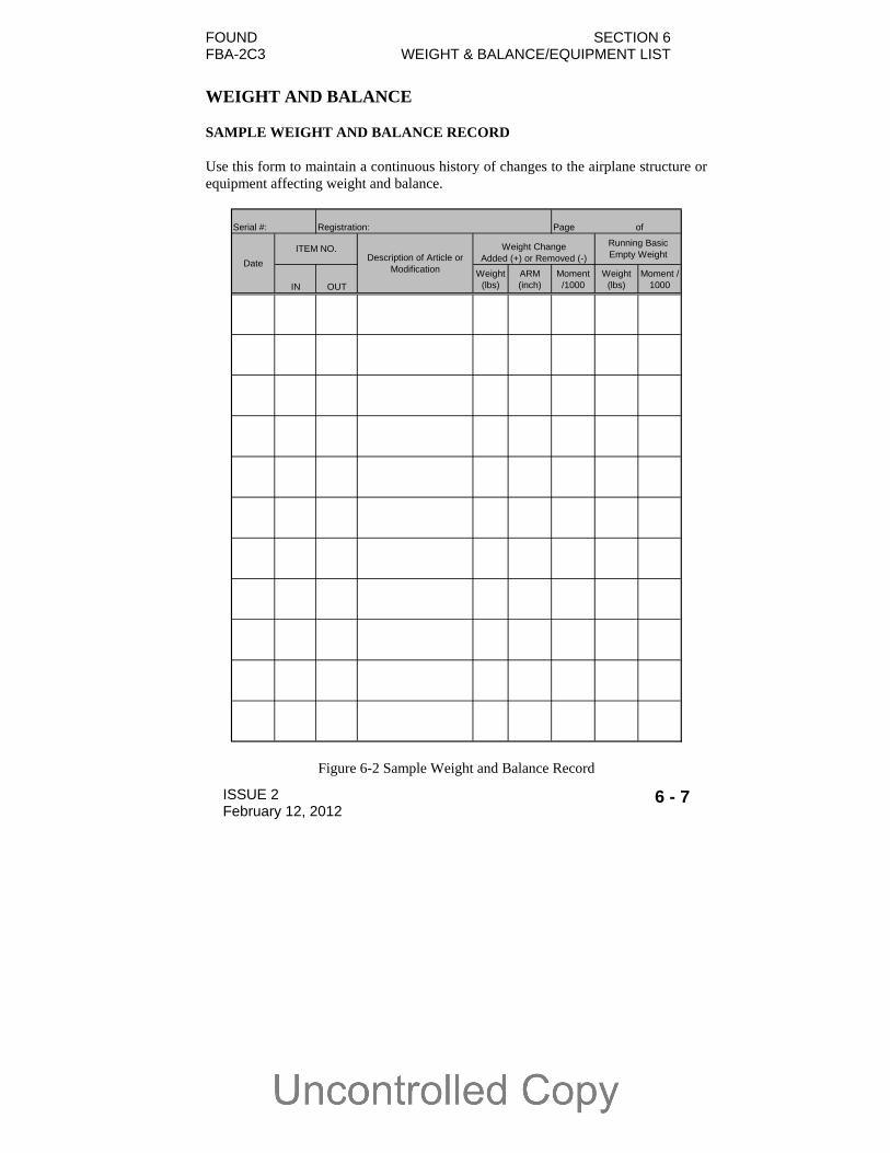
WEIGHT AND BALANCE SAMPLE WEIGHT AND BALANCE RECORD Use this form to maintain a continuous history of changes to the airplane structure or equipment affecting weight and balance.
Serial #: Registration: Page of
IN OUT
Weight (lbs)
ARM (inch)
Moment /1000
Weight (lbs)
Moment / 1000
Description of Article or Modification
ITEM NO.
Date
Weight Change Added (+) or Removed (-)
Running Basic Empty Weight
Figure 6-2 Sample Weight and Balance Record
SECTION 6 FOUND WEIGHT & BALANCE/EQUIPMENT LIST FBA-2C3
6 - 8 ISSUE 2 February 12, 2012
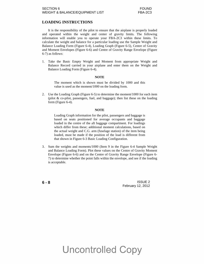
LOADING INSTRUCTIONS
It is the responsibility of the pilot to ensure that the airplane is properly loaded
and operated within the weight and center of gravity limits. The following information will enable you to operate your FBA-2C3 within these limits. To calculate the weight and balance for a particular loading use the Sample Weight and Balance Loading Form (Figure 6-4), Loading Graph (Figure 6-5), Centre of Gravity and Moment Envelopes (Figure 6-6) and Centre of Gravity Range Envelope (Figure 6-7) as follows:
1. Take the Basic Empty Weight and Moment from appropriate Weight and
Balance Record carried in your airplane and enter them on the Weight and Balance Loading Form (Figure 6-4).
NOTE
The moment which is shown must be divided by 1000 and this value is used as the moment/1000 on the loading form.
2. Use the Loading Graph (Figure 6-5) to determine the moment/1000 for each item
(pilot & co-pilot, passengers, fuel, and baggage); then list these on the loading form (Figure 6-4).
NOTE
Loading Graph information for the pilot, passengers and baggage is based on seats positioned for average occupants and baggage loaded in the centre of the aft baggage compartment. For loadings which differ from these; additional moment calculations, based on the actual weight and C.G. arm (fuselage station) of the item being loaded, must be made if the position of the load is different from that shown in Figure 6-3 Basic Loading Configuration.
3. Sum the weights and moments/1000 (Item 9 in the Figure 6-4 Sample Weight
and Balance Loading Form). Plot these values on the Centre of Gravity Moment Envelope (Figure 6-6) and on the Centre of Gravity Range Envelope (Figure 6-7) to determine whether the point falls within the envelope, and see if the loading is acceptable.
FOUND SECTION 6 FBA-2C3 WEIGHT & BALANCE/EQUIPMENT LIST
ISSUE 2 February 12, 2012 6 - 9
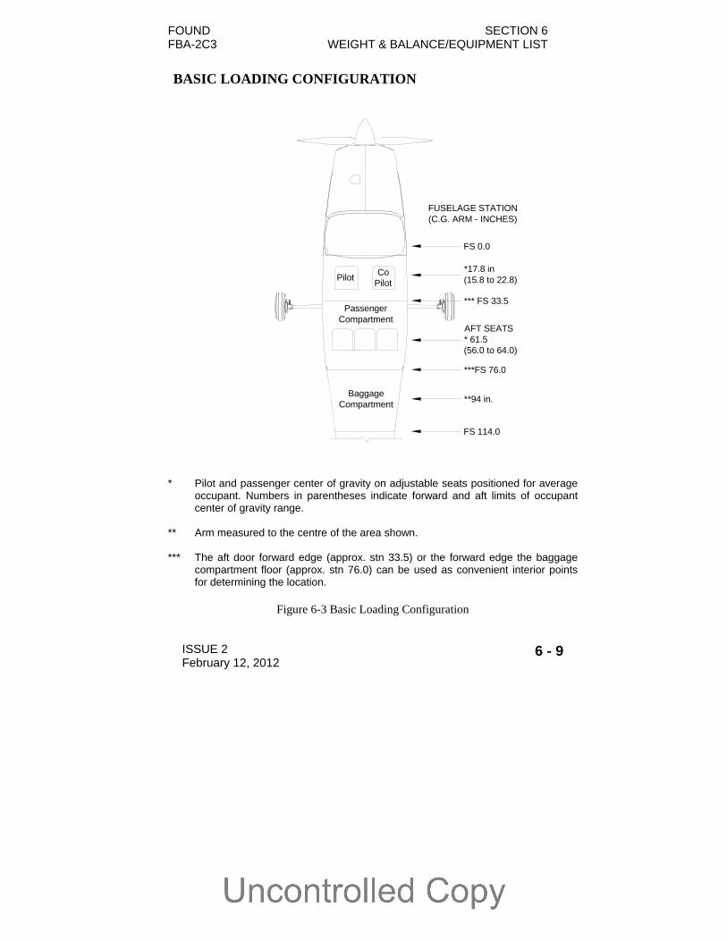
BASIC LOADING CONFIGURATION
* Pilot and passenger center of gravity on adjustable seats positioned for average
occupant. Numbers in parentheses indicate forward and aft limits of occupant center of gravity range.
** Arm measured to the centre of the area shown. *** The aft door forward edge (approx. stn 33.5) or the forward edge the baggage
compartment floor (approx. stn 76.0) can be used as convenient interior points for determining the location.
Figure 6-3 Basic Loading Configuration
PilotCo
Pilot
BaggageCompartment
PassengerCompartment
FUSELAGE STATION(C.G. ARM - INCHES)
FS 0.0
*** FS 33.5
***FS 76.0
FS 114.0
*17.8 in(15.8 to 22.8)
AFT SEATS* 61.5(56.0 to 64.0)
**94 in.
SECTION 6 FOUND WEIGHT & BALANCE/EQUIPMENT LIST FBA-2C3
6 - 10 ISSUE 2 February 12, 2012
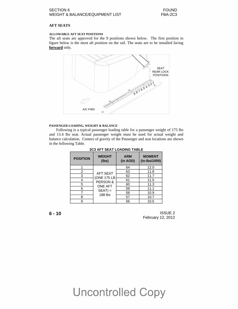
AFT SEATS ALLOWABLE AFT SEAT POSITIONS
The aft seats are approved for the 9 positions shown below. The first position in figure below is the most aft position on the rail. The seats are to be installed facing forward only.
PASSENGER LOADING, WEIGHT & BALANCE
Following is a typical passenger loading table for a passenger weight of 175 lbs and 13.4 lbs seat. Actual passenger weight must be used for actual weight and balance calculation. Centers of gravity of the Passenger and seat locations are shown in the following Table.
123456789
A/C FWD
SEAT REAR LOCKPOSITIONS
POSITIONWEIGHT
(lbs)ARM
(in AOD)MOMENT
(in-lbs/1000)
1 64 12.02 63 11.83 62 11.74 61 11.55 60 11.36 59 11.17 58 10.98 57 10.79 56 10.5
AFT SEAT(ONE 175 LBPERSON &ONE AFTSEAT) =188 lbs
2C3 AFT SEAT LOADING TABLE
FOUND SECTION 6 FBA-2C3 WEIGHT & BALANCE/EQUIPMENT LIST
ISSUE 2 February 12, 2012 6 - 11
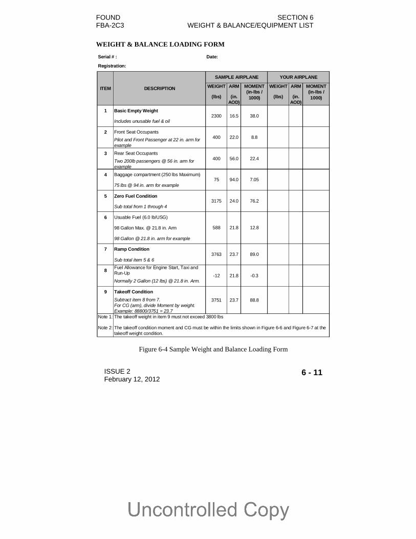
WEIGHT & BALANCE LOADING FORM
Figure 6-4 Sample Weight and Balance Loading Form
Serial # : Date:
Registration:
WEIGHT ARM WEIGHT ARM
(lbs) (in. AOD)
(lbs) (in. AOD)
1 Basic Empty Weight
Includes unusable fuel & oil
2 Front Seat Occupants
Pilot and Front Passenger at 22 in. arm for example
3 Rear Seat Occupants
Two 200lb passengers @ 56 in. arm for example
4 Baggage compartment (250 lbs Maximum)
75 lbs @ 94 in. arm for example
5 Zero Fuel Condition
Sub total from 1 through 4
6 Usuable Fuel (6.0 lb/USG)
98 Gallon Max. @ 21.8 in. Arm
98 Gallon @ 21.8 in. arm for example
7 Ramp Condition
Sub total item 5 & 6
8Fuel Allowance for Engine Start, Taxi and Run-Up
Normally 2 Gallon (12 lbs) @ 21.8 in. Arm.
9 Takeoff Condition
Subtract item 8 from 7.For CG (arm), divide Moment by weight.Example: 88800/3751 = 23.7
Note 1:
Note 2:
23.7
24.0
21.8
23.7
21.8
The takeoff weight in item 9 must not exceed 3800 lbs
The takeoff condition moment and CG must be within the limits shown in Figure 6-6 and Figure 6-7 at the takeoff weight condition.
3175
588 12.8
3751 88.8
3763
2300 38.0
400 8.8
16.5
22.0
SAMPLE AIRPLANE YOUR AIRPLANE
DESCRIPTIONITEM MOMENT(in-lbs / 1000)
MOMENT(in-lbs / 1000)
89.0
-12 -0.3
400 22.4
75 7.05
76.2
56.0
94.0

SECTION 6 FOUND WEIGHT & BALANCE/EQUIPMENT LIST FBA-2C3
6 - 12 ISSUE 2 February 12, 2012
LOADING GRAPH
Figure 6-5 Loading Graph
0
100
200
300
400
500
600
700
05
1015
2025
3035
4045
Lo
ad M
om
ent
/ 100
0 (i
n-l
bs)
Weight (lb)
Pilo
t & F
ront
P
asse
nger
@
15.8
"
Fue
l 6.
0lb/
Gal
@ 2
1.8"
Pilo
t & F
ront
P
asse
nger
@
22.8
"
Aft
Sea
t: P
asse
nger
or
Bag
gage
@
56.
0"
Aft
Sea
t: P
asse
nger
or
Bag
gage
@
64.
0"
Bag
gage
C
ompa
rtm
ent
@ 9
4.0"

FOUND SECTION 6 FBA-2C3 WEIGHT & BALANCE/EQUIPMENT LIST
ISSUE 2 February 12, 2012 6 - 13
CENTER OF GRAVITY MOMENT ENVELOPE
Figure 6-6 Centre of Gravity Moment Envelope
2000
2200
2400
2600
2800
3000
3200
3400
3600
3800
4000
0 10 20 30 40 50 60 70 80 90 100
Airplane Moment / 1000 (in-lbs)
Air
pla
ne
We
igh
t (l
bs)

SECTION 6 FOUND WEIGHT & BALANCE/EQUIPMENT LIST FBA-2C3
6 - 14 ISSUE 2 February 12, 2012
CENTER OF GRAVITY RANGE ENVELOPE
Figure 6-7 Centre of Gravity Range Envelope
2000
2200
2400
2600
2800
3000
3200
3400
3600
3800
4000
14 15 16 17 18 19 20 21 22 23 24 25
Airplane C.G. Location - Aft of Datum (in.)
Air
pla
ne
Wei
gh
t (l
bs
)
FOUND SECTION 6 FBA-2C3 WEIGHT & BALANCE/EQUIPMENT LIST
ISSUE 2 REV 1 March 14, 2013 6 - 15
CARRIAGE OF CARGO
There are two distinct areas where cargo may be carried (refer to Figure 6-3): The passenger compartment located behind the crew seats (after
removal of one or more of the three passenger seats) The baggage compartment located behind the three passenger seats
It is recommended that the heaviest cargo be located in the forward part of the airplane and the lightest in the rear part of the airplane in order to keep the centre of gravity within limits.
It is essential to properly secure cargo before flight.
CARGO TIE-DOWN
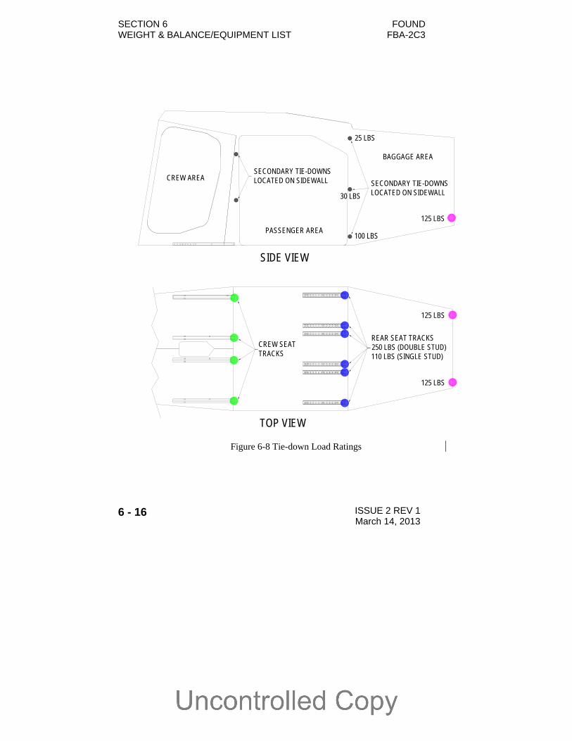
The airplane is equipped with multiple tie-down points. The load ratings for the tie-down points are given in Figure 6-8.
Only the total rated load of the tie-downs located aft of the cargo are to be considered when determining adequate restraint.
For example, a 750 lbs load would require a minimum of three tie-downs rated at 250 lbs each to be located aft of the load. It should also be noted that additional tie-downs located forward of the load would also be needed to properly secure the cargo.
Rope, strap or cable used for tie-down should be rated at a minimum of ten times the load capacity of the tie-down used.
SECTION 6 FOUND WEIGHT & BALANCE/EQUIPMENT LIST FBA-2C3
6 - 16 ISSUE 2 REV 1 March 14, 2013
CREW AREA
PASSENGER AREA
BAGGAGE AREA
CREW SEATTRACKS
REAR SEAT TRACKS250 LBS (DOUBLE STUD)110 LBS (SINGLE STUD)
125 LBS
125 LBS
TOP VIEW
SIDE VIEW
125 LBS
SECONDARY TIE-DOWNS LOCATED ON SIDEWALL SECONDARY TIE-DOWNS
LOCATED ON SIDEWALL
100 LBS
30 LBS
25 LBS
Figure 6-8 Tie-down Load Ratings

FOUND SECTION 6 FBA-2C3 WEIGHT & BALANCE/EQUIPMENT LIST
ISSUE 2 REV 1 March 14, 2013 6 - 17
PASSENGER COMPARTMENT (CARGO TIE-DOWN)
The primary passenger compartment tie-down points are the six rear seat tracks. Tie-down points are created by installing either single or double stud load ring fittings in the tracks.
Single Stud Track Fitting Double Stud Track Fitting It should be noted that single stud fittings are typically rated at half the strength
of the double stud fittings. Use a double stud fitting to achieve the full strength of the seat track tie-down point.
Figure 6-9 shows single stud fittings installed in the rear tracks.

SECTION 6 FOUND WEIGHT & BALANCE/EQUIPMENT LIST FBA-2C3
6 - 18 ISSUE 2 REV 1 March 14, 2013
Figure 6-9 Single Stud Load Rings in Rear Seat Tracks The rear seat track tie-down points should be used in conjunction with the four
tie-down points located at the ends of the crew seat tracks to secure cargo in the passenger compartment. Figure 6-10 shows the location of the tie-down rings on the crew seat tracks.
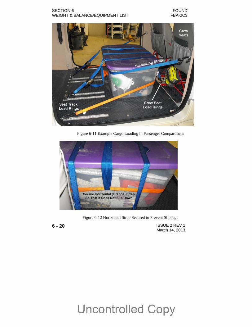
There are four tie-down points located on the sides of the cabin just behind the crew seats. These tie-downs should not be used as the primary tie-down points for securing cargo. They should only be used to “stabilize” the cargo and prevent it from shifting. Figure 6-11 shows these tie-down points being used in conjunction with the primary tie-down points to secure a cargo bin.
There are also six tie-down points located on the sides of the cabin just behind the passenger seats. Again these tie-downs should not be used as the primary attachment points for securing cargo in the passenger compartment. They should only be used in conjunction with the rear seat track tie-down points.
FOUND SECTION 6 FBA-2C3 WEIGHT & BALANCE/EQUIPMENT LIST
ISSUE 2 REV 1 March 14, 2013 6 - 19
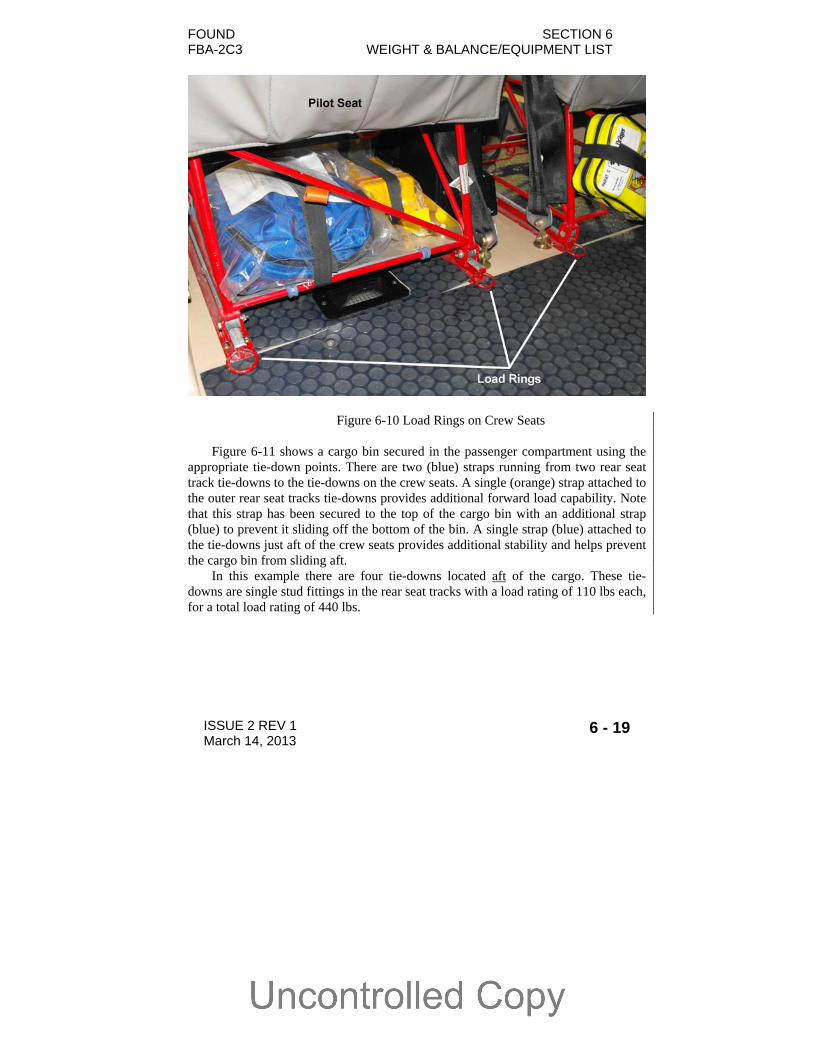
Figure 6-10 Load Rings on Crew Seats Figure 6-11 shows a cargo bin secured in the passenger compartment using the
appropriate tie-down points. There are two (blue) straps running from two rear seat track tie-downs to the tie-downs on the crew seats. A single (orange) strap attached to the outer rear seat tracks tie-downs provides additional forward load capability. Note that this strap has been secured to the top of the cargo bin with an additional strap (blue) to prevent it sliding off the bottom of the bin. A single strap (blue) attached to the tie-downs just aft of the crew seats provides additional stability and helps prevent the cargo bin from sliding aft.
In this example there are four tie-downs located aft of the cargo. These tie-downs are single stud fittings in the rear seat tracks with a load rating of 110 lbs each, for a total load rating of 440 lbs.
SECTION 6 FOUND WEIGHT & BALANCE/EQUIPMENT LIST FBA-2C3
6 - 20 ISSUE 2 REV 1 March 14, 2013
Figure 6-11 Example Cargo Loading in Passenger Compartment
Figure 6-12 Horizontal Strap Secured to Prevent Slippage
FOUND SECTION 6 FBA-2C3 WEIGHT & BALANCE/EQUIPMENT LIST
ISSUE 2 REV 1 March 14, 2013 6 - 21
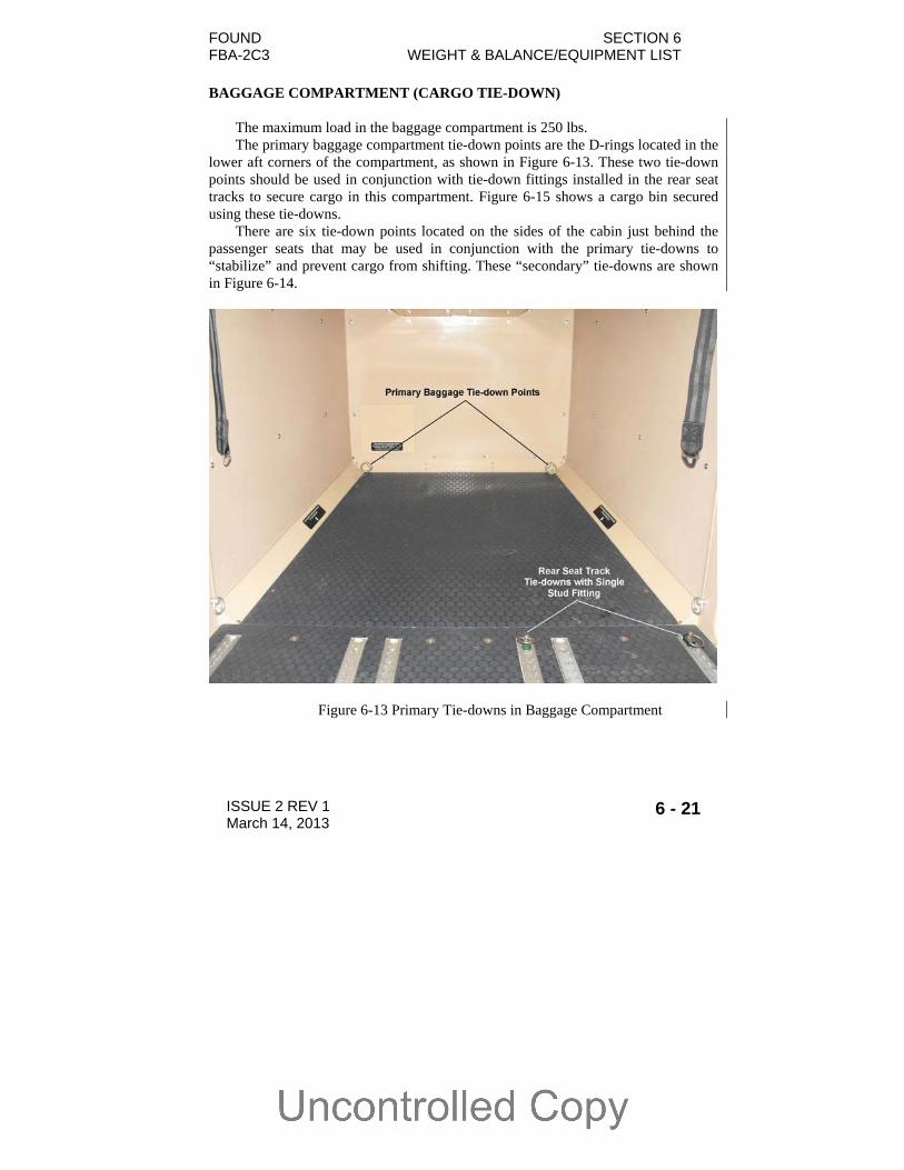
BAGGAGE COMPARTMENT (CARGO TIE-DOWN)
The maximum load in the baggage compartment is 250 lbs. The primary baggage compartment tie-down points are the D-rings located in the
lower aft corners of the compartment, as shown in Figure 6-13. These two tie-down points should be used in conjunction with tie-down fittings installed in the rear seat tracks to secure cargo in this compartment. Figure 6-15 shows a cargo bin secured using these tie-downs.
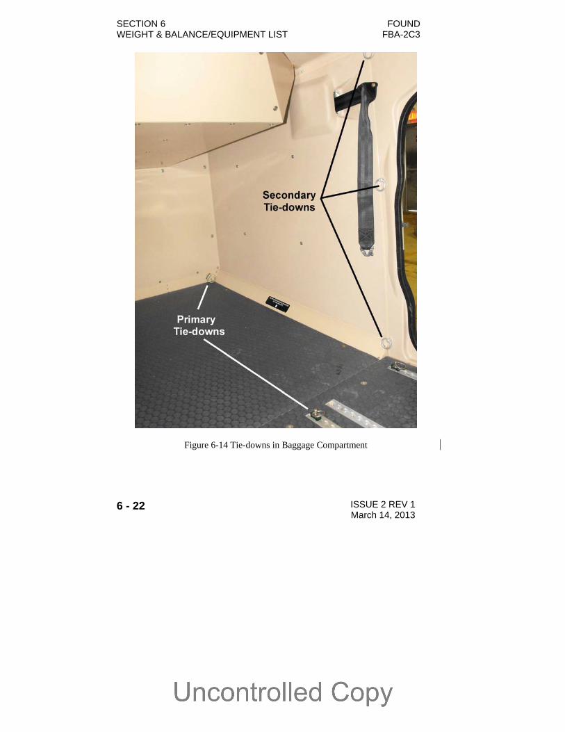
There are six tie-down points located on the sides of the cabin just behind the passenger seats that may be used in conjunction with the primary tie-downs to “stabilize” and prevent cargo from shifting. These “secondary” tie-downs are shown in Figure 6-14.
Figure 6-13 Primary Tie-downs in Baggage Compartment
SECTION 6 FOUND WEIGHT & BALANCE/EQUIPMENT LIST FBA-2C3
6 - 22 ISSUE 2 REV 1 March 14, 2013
Figure 6-14 Tie-downs in Baggage Compartment

FOUND SECTION 6 FBA-2C3 WEIGHT & BALANCE/EQUIPMENT LIST
ISSUE 2 REV 1 March 14, 2013 6 - 23
Figure 6-15 Cargo Bin Secured in Baggage Compartment

SECTION 6 FOUND WEIGHT & BALANCE/EQUIPMENT LIST FBA-2C3
6 - 24 ISSUE 2 REV 1 March 14, 2013
CABIN HEIGHT MEASUREMENTS
FS 0.0 FS 33.5 FS 76.0
FS 94.0
FS 114.0
52.3 48.1 37.3 32.1
Figure 6-16 Internal Cabin Dimensions
FOUND SECTION 6 FBA-2C3 WEIGHT & BALANCE/EQUIPMENT LIST
ISSUE 2 REV 1 March 14, 2013 6 - 25
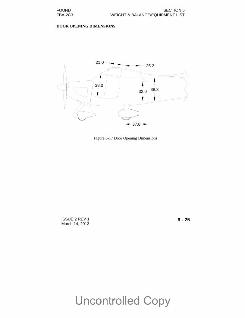
DOOR OPENING DIMENSIONS
Figure 6-17 Door Opening Dimensions
37.8
32.0 38.3
25.2
38.0
21.0
SECTION 6 FOUND WEIGHT & BALANCE/EQUIPMENT LIST FBA-2C3
6 - 26 ISSUE 2 REV 1 March 14, 2013
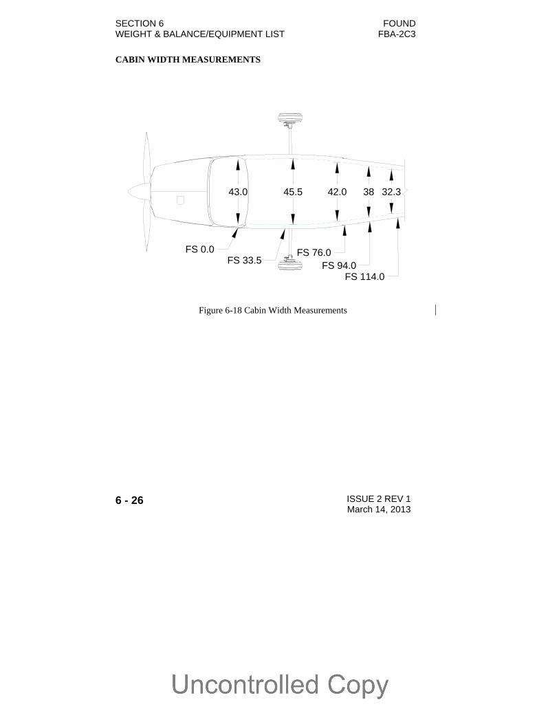
CABIN WIDTH MEASUREMENTS
43.0
FS 0.0FS 33.5
FS 76.0FS 94.0
FS 114.0
45.5 42.0 32.338
Figure 6-18 Cabin Width Measurements
FOUND SECTION 6 FBA-2C3 WEIGHT & BALANCE/EQUIPMENT LIST
ISSUE 2 REV 1 March 14, 2013 6 - 27
COMPREHENSIVE EQUIPMENT LIST
A comprehensive list of the equipment installed in an FBA-2C3 airplane is
provided with the Pilot’s Operating Handbook at the time of delivery.