section 590.00 idaho transportation department...
TRANSCRIPT

Quality Assurance ITD STQP 590.00
1/13
SECTION 590.00 – IDAHO TRANSPORTATION DEPARTMENT (ITD) SAMPLER / TESTER QUALIFICATION PROGRAM (STQP)
590.10 Individual Test Method Qualifications. 590.10.1Non-ITD Personnel.

Quality Assurance ITD STQP 590.00
1/13
Section 590.00 – Idaho Transportation Department (ITD) Sampler / Tester Qualification Program (STQP)
Information found in this section can also be found in the Laboratory Operations Manual, Section 250.
Qualifications are granted by ITD through the STQP. The purpose of the ITD STQP is for conformance to State and Federal requirements. All individuals shall be qualified who sample or test on ITD projects. Valid sampler / tester qualification for ITD projects is only available through this program.
The ITD STQP includes Six (6) Western Alliance for Quality Transportation Construction (WAQTC) modules, two (2) ITD STQP modules, and nineteen (19) individual test method qualifications.
Details on the five WAQTC and three ITD STQP modules are located in the Registration Policies and Information Hand book (RP &IH) which can be downloaded from the Sampler Tester qualification web page. http://itd.idaho.gov/highways/ops/materials/techqual/techqual.asp. Details on individual test method qualifications are found in section 590.10.
QUALIFICATION (S) ARE VALID WHEN POSTED ON THE ITD’S WEB PAGE UNDER “INSPECTOR AND SAMPLER / TESTER QUALIFICATION (WAQTC).
590.10 Individual Test Method Qualifications. Table 1 below lists the individual test methods that require qualification. Prerequisite Sampler / Tester (WAQTC) qualifications are required before any performance examination can occur. Performance exam documentation (Registration Form, Rights and Responsibilities form, and completed Performance Exam Checklist) shall be submitted to HQ Central Laboratory. The Individual Qualification certificate is form ITD-949 for all test methods. The following performance exam checklists are to be used along with the appropriate AASHTO Testand Idaho Test methods .

Quality Assurance ITD STQP 590.00
1/13
Table 1 Individual Test Methods
Test Method Test Reference Notes For Pre-Qualification
Aggregates
Cleanness Value Idaho IT 72 AgTT Qualification is required.
Specific Gravity and Absorption of Fine Aggregate
Idaho IT 144
AgTT Qualification is required. Performance exam administered by HQ
Central Laboratory Bulk Density (“Unit Weight”) and
Voids in Aggregate AASHTO T19 AgTT Qualification is required.
Specific Gravity and Absorption of Fine Aggregate
AASHTO T 84 AgTT Qualification is required.
Uncompacted Void Content Of Fine Aggregate
AASHTO T 304 AgTT Qualification is required.
Flat and Elongated Particles in Coarse Aggregate
ASTM D4791 AgTT Qualification is required.
Bituminous Materials
Saybolt Viscosity Idaho IT 61 AsTT Qualification is required.
Bituminous Coating Idaho IT 96 AsTT Qualification is required.
Anti-strip Detection Idaho IT 99
Hveem Stability AASHTO T246 AsTT Qualification is required.
Performance exam administered by HQ Materials
Effect of Water on Compressive Strength of Compacted
Bituminous Mixtures AASHTO T165
AsTT Qualification is required. Performance exam administered by HQ
Central Laboratory
Preparation of Test Specimens for Cal. Kneading Compactor AASHTO T247
AsTT Qualification is required. Performance exam administered by HQ
Central Laboratory Density of In-place HMA
Pavement by Electronic Surface Contact Device
AASHTO TP 68 DTT Qualification is required.
Bulk Specific Gravity and Density of Compacted Hot Mix Asphalt (HMA) using Automatic Vacuum Sealing Method (CoreLok)
AASHTO T 331 AsTT Qualification is required.
Field Sampling Bituminous Material after Compaction (Obtaining Cores)
WAQTC TM 11 AsTT Qualification is required.
Soils
Determining the Plastic Limit and Plasticity Index of Soils AASHTO T90 EbTT Qualification is required.
Determining the Liquid Limit of Soils AASHTO T89 EbTT Qualification is required.
Specific Gravity of Soils AASHTO T100 EbTT Qualification is required.
Concrete
Sampling & Fabrication of 2” Cube Specimens using Grout or
Mortar AASHTO TP83 CTT Qualification is required.

Quality Assurance ITD STQP 590.00
1/13
PERFORMANCE EXAM CHECKLIST CLEANNESS VALUE – IDAHO IT 72
Record the symbols “P” for passing or “F” for failing on each step of the checklist.
Procedure Element Trial 1 Trial 2
General
1. The sample was maintained moist in sealed container. 1
2. The sample is equal to 1000 ± 50 grams. 2
3. There is 7 ml of SE solution in SE tube.3 3
4. The graduate assembly including sieves, funnel and 500 ml graduate
cylinder is properly put together. 4
5. CCM sample was placed in washing vessel or jar and water was
added just covering the aggregate. 5
Mechanical Method
6. The vessel was secure in the shaker. 6
7. Agitation was started after one (1) minute. 7
8. The vessel was agitated for two minutes. 8
Hand Method
9. Agitation was started after one (1) minute. 9
10. The vessel was properly rotated with 150mm radius. 10
11. Vessel was agitated 3 complete rotations per second. 11
12. Vessel was agitated for one (1) full minute. 12
Measure for Cleanness
13. All contents of vessel or jar were washed over sieves into the 500 ml
graduate cylinder. 13
14. Cylinder was rapidly turned upside down at 180º, ten (10) times. 14
15. Mixture was poured into SE cylinder to 15 inch mark. 15
16. SE Cylinder was rotated at least ten (10) complete cycles. Bubble
traveled full length of tube. 16
17. Cylinder was allowed to stand 20 minutes on work table free from
vibrations. 17
18. The sediment reading was to the nearest 0.1 inch. 18
19. Calculations were accurate to the nearest whole number. 19
Comments: First Attempt: Pass Fail Second Attempt: Pass Fail
Testing Technician’s Name: WAQTC # : Date:
Examiner’s Name: Signature
Idaho Standards 510.00
1/08 Idaho IT-144
Idaho Standard Method of Test for
Specific Gravity and Absorption of Fine
Aggregate Using Automatic Vacuum Sealing
(CoreLok) Method
Idaho IT-144-08
1 Scope
1.1 This standard covers the determination of specific gravity and absorption of fine aggregates.
1.2 The values are stated in SI units and are regarded as the standard units.
1.3 This standard may involve hazardous materials, operations and equipment. This standard does not
purport to address all of the safety problems associated with its use. It is the responsibility of the
user of this standard to consult and establish appropriate safety and health practices and determine
the applicability of regulatory limitations prior to use.
2 Referenced Documents
2.1 AASHTO Standards:
M 132, Terms Relating to Density and Specific Gravity of Solids, Liquids and Gases
M 231, Weighing Devices Used in the Testing of Materials
T 2, Standard Practice for Sampling of aggregates
T 19, Standard Test Method for Bulk Density (Unit Weight) and Voids in Aggregate
T 248, Standard Practice for Reducing Samples of Aggregate to Testing Size
T255, Total Evaporable Moisture Content of Aggregate by Drying
2.2 Other Standards
CoreLok Operational Instructions (InstroTek, Inc.)
3 Terminology
3.1 absorption—the increase in the mass of aggregate due to water in the pores of the material, but not
including water adhering to the outside surface of the particles, expressed as a percentage of the dry
mass. The aggregate is considered “dry” when it has been maintained at a temperature of 110 ± 5ºC
for sufficient time to remove all uncombined water.
3.2 specific gravity—the ratio of the mass (or weight in air) of a unit volume of a material to the mass
of the same volume of water at stated temperatures. Values are dimensionless.
3.3 apparent specific gravity—the ratio of the weight in air of a unit volume of the impermeable
portion of aggregate at a stated temperature to the weight in air of an equal volume of gas-free
distilled water at a stated temperature.

Idaho Standards 510.00
1/08 Idaho IT-144
3.4 bulk specific gravity—the ratio of the weight in air of a unit volume of aggregate (including the
permeable and impermeable voids in the particles, but not including the voids between particles) at
a stated temperature to the weight in air of an equal volume of gas-free distilled water at a stated
temperature.
3.5 bulk specific gravity (SSD)—the ratio of the mass in air of a unit volume of aggregate, including
the mass of water within the voids filled to the extent achieved by vacuum saturating (but not
including the voids between particles) at a stated temperature, compared to the weight in air of an
equal volume of gas-free distilled water at a stated temperature.
4 Summary Of Method
4.1 Sufficient fine aggregate sample is dried to constant mass and representative dry fine aggregate
samples of the same material are selected for testing. One sample is sealed in a vacuum chamber
inside a plastic bag and opened under water for rapid saturation of the aggregate. The dry mass and
submerged mass of the sample is used for calculation of apparent specific gravity. Other samples of
the same aggregate are tested in a known volume metal pycnometer. The known mass of the
pycnometer with water, mass of the dry aggregate, and mass of the dry aggregate and pycnometer
filled with water is averaged and used for calculation of bulk specific gravity oven dry (OD.) The
results from the samples tested are used to calculate absorption, and bulk specific gravity saturated-
surface-dry (SSD).
5 Apparatus
5.1 Balance—A balance that conforms to AASHTO M231. The balance shall be sensitive, readable
and accurate to 0.1% of the test sample mass. The balance shall be equipped with suitable
apparatus for suspending the sample in water.
5.2 Water Bath—A large container that will allow for completely submerging the sample in water
while suspended, equipped with an overflow outlet for maintaining a constant water level.
Temperature controls may be used to maintain the water temperature at 25 ± 1° C (77 ± 2 °F).
Note 1—It is preferable to keep the water temperature constant by using a temperature
controlled heater. Also, to reduce the chance for the bag to touch the sides of the water tank, it is
preferable to elevate the water tank to a level at which the sample can be placed on the weighing
mechanism while the operator is standing up (waist height), and the placement of the sample and
the bag in the water tank can easily be inspected.
5.3 Sample holder for water displacement of the sample, having no sharp edges.
5.4 Vacuum Chamber—with a pump capable of evacuating a sealed and enclosed chamber to a
pressure of 6 mm Hg, when at sea level. The device shall automatically seal the plastic bag and
exhaust air back into the chamber in a controlled manner to ensure proper conformance of the
plastic to the specimen. The air exhaust and vacuum operation time shall be set at the factory so
that the chamber is brought to atmospheric pressure in 80 to 125 seconds, after the completion of
the vacuum operations.
5.5 A Vacuum Measurement Gauge, independent of the vacuum sealing device, that could be placed
directly inside the chamber to verify vacuum performance and the chamber door sealing condition
of the unit. The gauge shall be capable of reading down to 3 mm Hg and readable to ± 1 mm Hg.
The gauge shall be NIST traceable.

Idaho Standards 510.00
1/08 Idaho IT-144
5.6 Plastic Bags, used with the vacuum device, shall have a minimum opening of 235 mm (9.25 in.)
and maximum opening of 260 mm (10.25 in.). The bags shall be of plastic material, shall be
puncture resistant, and shall be impermeable to water. The bags shall have a minimum thickness of
0.127mm (0.005 in.). The manufacturer shall provide the apparent specific gravity for the bags.
5.7 Metal pycnometer and lid, with 137 ± 0.13 mm (5.375 ± 0.005 in.) inside diameter (ID) and 89 ±
0.41 mm (3.5 ± 0.016 in.) height, for testing fine aggregates. The pycnometer shall be machined to
be smooth on all surfaces. The inside of the lid shall be machined at a 5° angle to create an inverted
conical surface.
5.8 Pycnometer clamping device to hold and secure the lid on the metal pycnometer from lifting during
fine aggregate tests. The device shall be provided with a level indicator.
5.9 Syringe with a needle no larger in diameter than 3 mm (0.125 in.)
5.10 Thermometer or other temperature device with range to 40ºC (100ºF) accurate to ±1º.
5.11 Isopropyl alcohol – Technical Grade
5.12 Accessories— A bag cutting knife or scissors, spray bottle for the isopropyl alcohol, a bucket large
enough to allow the pycnometer to be fully submerged in water, water containers to dispense water
into pycnometer during testing, small paint brush and 25 mm (1 in.) wide aluminum spatula.
6 Verification
6.1 System Verification: The vacuum settings of the vacuum chamber shall be verified once every 12
months and after major repairs and after each shipment or relocation.
6.1.1 Place the gauge inside the vacuum chamber and record the setting, while the vacuum unit is
operating. The gauge should indicate a pressure of 6 mm Hg or less. The unit shall not be used if
the gauge reading is above 6 mm Hg.
Note 2— In line vacuum gauges, while capable of indicating vacuum performance of the
pump, are not suitable for use in enclosed vacuum chambers and cannot accurately
measure vacuum levels.
6.2 Calibration of Pycnometer:
6.2.1 Prior to testing, condition the pycnometer to 25 ± 1°C (77 ± 2°F) by placing it inside a bucket of
water that is maintained at 25 ± 1°C (77 ± 2°F). Place the pycnometer clamping device on a level
surface. Use a level indicator or the provided level to level the device.
Note 3 – The clamping device must be protected from hot or cold ambient laboratory
temperatures that are more or less than 25 ± 1°C (77 ± 2°F).
6.2.2 Remove the pycnometer from the water bucket and dry it with a towel. Place the pycnometer in
the device and push it back until it makes contact with the stops.
6.2.3 Fill the pycnometer with 25 ± 1°C (77 ± 2°F) water to approximately 10 mm (0.375 in.) from the
top. Using the alcohol spray bottle, spray the surface of the water to remove bubbles.
6.2.4 Gently place the lid on the pycnometer and close the clamps on the device.
6.2.5 Using a syringe filled with 25 ± 1°C (77 ± 2°F) water, slowly fill the pycnometer through the
large fill hole on the lid post. Make sure the syringe tip is far enough in the pycnometer to be
below the water level. Gentle application in this step prevents formation of air bubbles inside the
pycnometer.

Idaho Standards 510.00
1/08 Idaho IT-144
6.2.6 Fill the pycnometer until water comes out of the 3 mm (1/8-in.) hole on the surface of the lid.
6.2.7 Wipe any remaining water from the top of the lid with a towel.
6.2.8 Place the entire device with the pycnometer on the scale and record the mass. Record the mass to
0.1 in the top portion of the Aggregate Worksheet. (See Appendix 1)
6.2.9 Clean the pycnometer and repeat steps 6.2.1 to 6.2.8 two more times and average the calibration
masses obtained in 6.2.8.
6.2.10 If the range for the 3 calibration masses is larger than 0.5 grams, then the test is not being run
correctly. Check to see if the device is level. Make certain the water injection with the syringe is
done below the pycnometer water surface and is applied gently. Check the water temperature.
Check the pycnometer temperature. Repeat the above procedure until you have three masses that
are within a 0.5 gram range.
6.2.11 The pycnometer must be re-calibrated daily prior to testing.
7 Sampling
7.1 Sampling shall be performed in accordance with AASHTO T 2.
7.2 Samples shall be dried to constant mass in accordance with AASHTO T255.
7.3 Samples shall be reduced in accordance with AASHTO T 248.
8 Procedures
8.1 Equipment Preparation:
Note 4 – Make certain water temperature used for this test remains at 25 ± 1°C (77 ± 2°F).
8.1.1 Prior to testing, condition the pycnometer to 25 ± 1°C (77 ± 2°F) by placing it inside a bucket of
water that is maintained at 25 ± 1°C (77 ± 2°F).
8.1.2 Remove the pycnometer from the water bucket and dry thoroughly with a towel.
8.1.3 Place the pycnometer clamping device on a level surface. Use a level indicator or the provided
level to level the device.
8.1.4 Place the empty pycnometer in the pycnometer clamping device and push it back until it makes
contact with the stops.
8.2 Determine Bulk Specific Gravity:
8.2.1 Oven dry to constant mass according to AASHTO T255, enough fine aggregate to obtain three
500 gram samples and one 1000 gram sample, reduced according to AASHTO T248..
8.2.2 Allow the sample to cool to 25 ± 1°C (77 ± 2°F).
8.2.3 Determine the mass of a 500 ± 1 gram dry sample, Trial 1, that is at 25 ± 1°C (77 ± 2°F) and
record to 0.1 on the Aggregate Worksheet.
8.2.4 Steps 8.2.5 to 8.2.13 shall be completed in less than 2 minutes.
8.2.5 Place approximately 500 ml of 25 ± 1°C (77 ± 2°F) water in the pycnometer (halfway full).

Idaho Standards 510.00
1/08 Idaho IT-144
8.2.6 Slowly and evenly pour the sample into the pycnometer. Make certain aggregate is not lost in the
process of filling the pycnometer. Use a brush if necessary to sweep any remaining fines into the
pycnometer. If any aggregate is lost during the process of filling the pycnometer, start the test
over.
8.2.7 Use a metal spatula and push it to the bottom of the pycnometer against the inside circumference.
Slowly and gently drag the spatula to the center of the pycnometer, removing the spatula after
reaching the center. Repeat this procedure in eight equal increments until the entire circumference
is covered. If necessary, use a squeeze water bottle to rinse any sample residue off the spatula into
the pycnometer.
8.2.8 Fill the pycnometer with 25 ± 1°C (77 ± 2 °F) water to approximately 10 mm (0.375 in.) of the
pycnometer rim. It is important the water level be kept at or below the 10 mm line to avoid spills
during lid placement.
8.2.9 Use the spray bottle filled with isopropyl alcohol to spray the top of the water to remove air
bubbles.
8.2.10 Gently place the lid on the pycnometer and lock the clamping device. Using the syringe, slowly
fill the pycnometer through the center hole on top of the lid post. Make sure the syringe tip is far
enough in the pycnometer to be below the water level. Gentle application in this step will prevent
formation of air bubbles inside the pycnometer.
8.2.11 Fill the pycnometer until water comes out of the 3 mm (1/8-in.) hole on the surface of the lid.
8.2.12 Wipe any remaining water from around the 3 mm (1/8-in.) hole with a towel.
Note 5 – Do not wipe water from the rim of the pycnometer if it seeps between the lid
and the pycnometer. Allow this water to remain.
8.2.13 Determine the mass of the sample, the pycnometer and the device. Record the mass to 0.1 in B of
the Aggregate Worksheet.
8.2.14 Discard the sample and prepare the equipment according to step 8.1.1 to 8.1.4.
8.2.15 Repeat steps 8.2.3 to 8.2.13 for another 500 ± 1 gram sample, Trial 2.
8.2.15.1 The difference in the mass of Trial 1 and Trial 2 recorded in B must be 1.0 gram or less. If the
difference is greater than 1.0, then repeat steps 8.2.14 and 8.2.15 using another 500 ±1 gram dry
sample.
8.2.16 Calculate the average mass for the two trials that are within 1 gram; record to 0.1 on Aggregate
Worksheet.
8.2.17 Record the average weight of the pycnometer from section 6.2.9 on Aggregate Worksheet.
8.3 Determine Apparent Specific Gravity:
8.3.1 Set the vacuum device according to manufacturer’s recommendation.
8.3.2 Tare the immersed weighing basket in the water bath.
8.3.3 Use a small plastic bag and inspect the bag to make sure there are no holes, stress points or side
seal discontinuities in the bag. If any of the above conditions are noticed, use another bag.
8.3.4 Determine the mass of the bag and record to 0.1 on Aggregate Worksheet.
Note 6—Always handle the bag with care to avoid creating weak points and punctures.
8.3.5 Determine the mass of a 1000 ± 1 gram sample of oven dry aggregate and record 0.1 at E on
Aggregate Worksheet.
Idaho Standards 510.00
1/08 Idaho IT-144
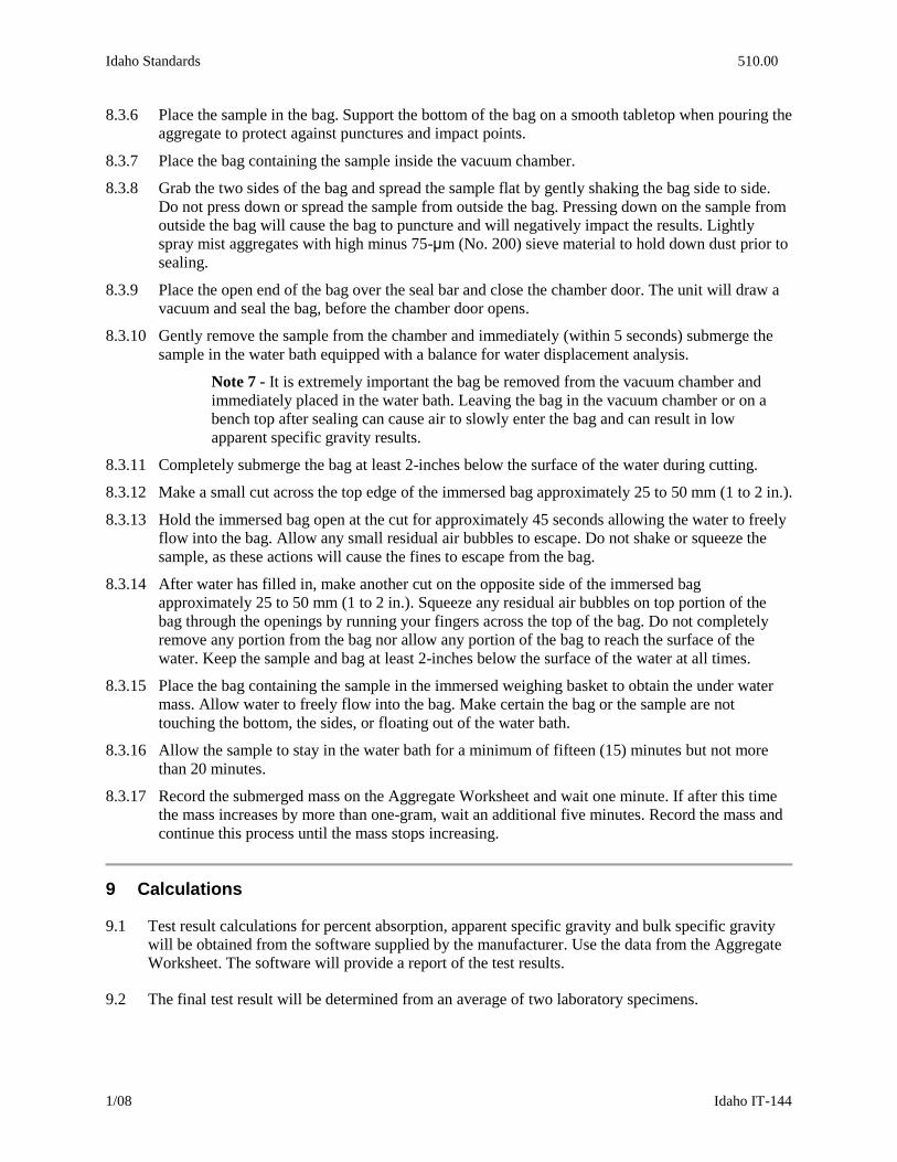
8.3.6 Place the sample in the bag. Support the bottom of the bag on a smooth tabletop when pouring the
aggregate to protect against punctures and impact points.
8.3.7 Place the bag containing the sample inside the vacuum chamber.
8.3.8 Grab the two sides of the bag and spread the sample flat by gently shaking the bag side to side.
Do not press down or spread the sample from outside the bag. Pressing down on the sample from
outside the bag will cause the bag to puncture and will negatively impact the results. Lightly
spray mist aggregates with high minus 75-μm (No. 200) sieve material to hold down dust prior to
sealing.
8.3.9 Place the open end of the bag over the seal bar and close the chamber door. The unit will draw a
vacuum and seal the bag, before the chamber door opens.
8.3.10 Gently remove the sample from the chamber and immediately (within 5 seconds) submerge the
sample in the water bath equipped with a balance for water displacement analysis.
Note 7 - It is extremely important the bag be removed from the vacuum chamber and
immediately placed in the water bath. Leaving the bag in the vacuum chamber or on a
bench top after sealing can cause air to slowly enter the bag and can result in low
apparent specific gravity results.
8.3.11 Completely submerge the bag at least 2-inches below the surface of the water during cutting.
8.3.12 Make a small cut across the top edge of the immersed bag approximately 25 to 50 mm (1 to 2 in.).
8.3.13 Hold the immersed bag open at the cut for approximately 45 seconds allowing the water to freely
flow into the bag. Allow any small residual air bubbles to escape. Do not shake or squeeze the
sample, as these actions will cause the fines to escape from the bag.
8.3.14 After water has filled in, make another cut on the opposite side of the immersed bag
approximately 25 to 50 mm (1 to 2 in.). Squeeze any residual air bubbles on top portion of the
bag through the openings by running your fingers across the top of the bag. Do not completely
remove any portion from the bag nor allow any portion of the bag to reach the surface of the
water. Keep the sample and bag at least 2-inches below the surface of the water at all times.
8.3.15 Place the bag containing the sample in the immersed weighing basket to obtain the under water
mass. Allow water to freely flow into the bag. Make certain the bag or the sample are not
touching the bottom, the sides, or floating out of the water bath.
8.3.16 Allow the sample to stay in the water bath for a minimum of fifteen (15) minutes but not more
than 20 minutes.
8.3.17 Record the submerged mass on the Aggregate Worksheet and wait one minute. If after this time
the mass increases by more than one-gram, wait an additional five minutes. Record the mass and
continue this process until the mass stops increasing.
9 Calculations
9.1 Test result calculations for percent absorption, apparent specific gravity and bulk specific gravity
will be obtained from the software supplied by the manufacturer. Use the data from the Aggregate
Worksheet. The software will provide a report of the test results.
9.2 The final test result will be determined from an average of two laboratory specimens.

Idaho Standards 510.00
1/08 Idaho IT-144
Appendix 1
Aggregate Worksheet
Weight of pycnometer and clamping device filled with water. 1. 2. 3. Avg.
Sample
Number or
Label
Trial Number A
Dry Sample Mass
(500 g)
B
Mass of
pycnometer
with sample
and water (g)
C
Plastic bag mass
(g)
D
Mass of two
rubber sheets
(g)
E
Dry Sample
Mass
(1000 g)
F
Mass of Sealed
sample opened
under water
1
2
3*
Avg
1
2
3*
Avg
1
2
3*
Avg
* Trial 3 is only necessary if the mass in B for the first 2 trials is larger than 1.0 grams.

PERFORMANCE EXAM CHECKLIST
SPECIFIC GRAVITY AND ABSORPTION OF FINE AGGREGATE USING AUTOMATIC VACUUM SEALING (CORELOK) METHOD IDAHO IT-144-08 Participant Name_____________________________________ Exam Date______________ Record ‘P’ For Passing “F” for failing each step of the checklist. Verification Element Trial 1 Trial 2
1. Pycnometer and lid placed inside a bucket of water at 25 ± 1C (77 ± 2F)? ______ ______ 2. Pycnometer and lid removed from water dried well and placed on clamping device until it makes contact with stops? ______ ______ 3. Pycnometer filled with 25 ± 1C (77 ± 2F) water to 10mm (3/8”) of top, sprayed with Isopropyl alcohol to remove air? ______ ______ 4. Lid gently placed on Pycnometer and clamped? ______ ______ 5. A syringe filled with 25 ± 1C (77 ± 2F) inserted in top of lid and gently added until water is expelled through the 3mm (1/8”) hole? ______ ______ 6. Water wiped from lid, device water and pycnometer weighed and recorded to 0.1 g? ______ ______ 7. Procedure repeated two additional times (no greater than 0.5 g difference) recorded to work sheet and averaged? ______ ______ Procedure Element Trial 1 Trial 2 8. Representative samples obtained per FOP for AASHTO T 2? ______ ______ 9. Reduced per FOP for AASHTO T 248? ______ ______ 10. Dried per FOP for AASHTO T 255? ______ ______ 11. Samples cooled to 25 ±1C (77 ± 2F)? ______ ______ 12. Three samples obtained @ 500g ±1g and one @ 1000g ± 1g? ______ ______ 13. Pycnometer and lid removed from water, dried and pycnometer placed on clamping device until it makes contact with stops? ______ ______ 14. Water added to pycnometer (at 25 ± 1C, 77 ± 2F) to approximately half full? ______ ______

Procedure Element Trial 1 Trial 2 15. Sample at 500 g ± 1g slowly added to pycnometer? ______ ______ 16. Metal spatula inserted against side of pycnometer and slowly pushed to center removed, repeated in eight equal increments? ______ ______ 17. Water added at 25 ± 1C (77 ± 2F) to within 10mm (3/8”) of rim? ______ ______ 18. Sprayed with isopropyl alcohol to remove air? ______ ______ 19. Lid gently placed on pycnometer with 3mm (1/8”) hole to the front and clamped? ______ ______ 20. Syringe filled with 25 ± 1C (77 ± 2F) water inserted in top of lid and water slowly added until it is expelled through 3mm (1/8”) hole? ______ ______ 21. Excess water wiped from lid? ______ ______ 22. Clamping device, pycnometer and sample mass recorded to 0.1 g? ______ ______ 23. Clamping device, pycnometer and sample mass determined no more than 2 minutes from time sample was submerged? ______ ______ 24. Second 500g ±1 g sample tested and mass recorded? ______ ______ 25. If recorded mass of first and second sample greater than 1 g, was a third 500 g ± 1 g sample tested? ______ ______ 26. Vacuum device set at manufacture’s recommended setting? ______ ______ 27. Small plastic bag inspected and mass determined to 0.1 g and recorded? ______ ______ 28. 1000 g ±1 g sample mass determined and recorded? ______ ______ 29. 1000 g ±1 g sample placed in the bag, supported by a smooth surface to prevent punctures? ______ ______ 30. Sample placed in vacuum device and spread flat by grasping both sides of bag and gently shaking? ______ ______ 31. Open end of bag placed over seal bar and closed? ______ ______ 32. Sample removed from vacuum chamber when door opens and submerged in 25 ± 1C (77 ± 2F) water bath within 5 seconds? ______ ______ 33. Bag maintained at a minimum depth of two inches? ______ ______ 34. A small cut made at corner of bag approximately 25 to 50mm (1” to 2”)? ______ ______ 35. Submerged bag held open until water flows freely into bag (approximately 45 seconds) ______ ______

Procedure Element Trial 1 Trial 2 36. A second cut approximately 25 to 50mm (1” to 2”) made to opposite side of bag? ______ ______ 37. Residual air removed from bag by running fingers across top of submerged bag? ______ ______ 38. Bag placed in weighing basket and water allowed to flow freely into bag? ______ ______ 39. Sample mass determined and recorded after 15 minutes but not more
than 20 minutes and recorded to 0.1g? ______ ______ 40. Test data entered into manufacture’s software to obtain test results? ______ ______ COMMENTS: First Attempt : Pass Fail Second Attempt: Pass Fail
Examiner Signature:_____________________________ Sampler / Tester Qualification #
Examiner Signature:___________________________________ Sampler / Tester Qualification #

Quality Assurance 590.00
1/13
PERFORMANCE EXAM CHECK LIST
BULK DENSITY (UNIT WEIGHT) AND VOIDS IN AGGREGATE AASHTO T 19
Participant Name: Exam Date: Record the symbols “P” for passing or “F” for failing on each step of the checklist: Procedure Elements: Trial#1 Trial#2 1. Obtain Sample. Use the FOP for AASHTO T 2. _____ _____
2. Aggregate dried to constant mass per the FOP for AASHTO T 255. _____ _____
3. Reduce Sample to required size. Use the FOP for AASHTO T 248. Sample shall be 125% to 200%
of the quantity needed to fill the measure. _____ _____
4. Inspect measure and other apparatus. Measure must be calibrated within the last 12 months, balance conforms to M 231, scoop/ shovel, & tamping rod in good working order. _____ _____
5. Rodding aggregate NMS 1 1/2” (37.5 mm) or less
a. Measure filled 1/3 full, leveled by hand, and rodded 25 times evenly distributed. The rod shall
not strike the bottom of the measure forcibly. _____ _____
b. Measure filled 2/3 full, leveled by hand, and rodded 25 times evenly distributed. The rod shall not penetrate into the first layer. _____ _____
c. Measure filled to overflowing, and rodded 25 times evenly distributed. The rod shall only
penetrate the top lift. The surface shall be leveled in such a way either by hand or straightedge that the number of slight projections equals the voids. _____ _____
6. Jigging: aggregates NMS greater than 1 ½” (37.5 mm) but not exceeding 5” (125mm)
a. Measure filled 1/3 full. _____ _____
b. Measure placed on concrete floor with opposite side lifted 2” (50mm) and allowed to
drop freely, continue this process for 25 times then drip it 25 more times from the opposite side for a total of 50 drops and leveled by hand. _____ _____
c. Measure filled 2/3 full and placed on concrete floor with opposite side lifted 2” (50mm) and allowed to drop freely, continue this process for 25 times then drip it 25 more times from the opposite side for a total of 50 drops and leveled by hand _____ _____
d. Measure filled to overflowing, and placed on concrete floor with opposite side lifted 2”
(50mm) and allowed to drop freely, continue this process for 25 times then drip it 25 more times from the opposite side for a total of 50 drops and leveled. The surface shall be leveled in such a way either by hand or straightedge that the number of slight projections equals the voids. _____ _____ OVER

Quality Assurance 590.00
1/13
Procedure Elements continued: Trial#1 Trial#2
7. Shoveling: only when specified
a. Measure filled to overflowing with shovel or scoop. Material placed into measure from a height not to exceed 2” (50mm) above the top of the measure minimizing segregation while filling. _____ _____
b. Measure leveled by hand or straightedge. The surface shall be leveled in such a way either
by hand or straightedge that the number of slight projections equals the voids. _____ _____
8. Determine mass of the measure and aggregate and mass of the measure alone to 0.1lb (0.05 kg). _____ _____
9. Determined & record the mass of Aggregate 0.1lb (0.05 kg). _____ _____
10. Calculate the bulk density to 1 lb/ft3 (10 kg/ m
3). _____ _____
COMMENTS: First Attempt : Pass Fail Second Attempt: Pass Fail
Examiner Signature:_________________________________________ Sampler / Tester Qualification # Examiner Signature:_________________________________________ Sampler / Tester Qualification #

Quality Assurance ITD STQP 590.00
1/13
PERFORMANCE EXAM CHECKLIST
Specific Gravity and Absorption of Fine Aggregate FOP for AASHTO T 84 Participant Name _ Exam Date __
____________________ Record the symbols “P” for passing or “F” for failing on each step of the checklist.
Sample Preparation Trial 1
Trial 2
1. Sampled according to AASHTO T 2?
2. Sample reduced according to AASHTO T 248 to approximately 2000 g?
3. Dried to a constant mass at 230 ±9º F, cooled to a comfortable handling
temp.?
4. Addition of 6% moisture to sample?
5. Allowed to stand 15 – 19 hours?
6. Uniformly dried by a current of warm air, with frequent stirring?
7. Mold placed on flat, non-absorbent surface and filled to over-flowing?
8. Sample compacted with 25 light drops of tamper from 0.2” above top of
sample?
9. Tamper allowed to fall freely under gravitational attraction?
10. Loose sand removed from around bases and mold lifted vertically?
11. Sample fails to slump on the first test?
12. If it does slump, is water added, sample covered and allowed to stand 30
minutes?
13. Drying continued, and test repeated at frequent intervals until sample slumps
slightly? Slight slump is when there is some evidence of slumping around the
circumference of the cone?
Testing Procedure
1. Split out two 500 gram samples that weigh within 0.2 grams of each other.
2. 1000 ml Pycnometer partially filled with water and first sample added?
3. Second sample dried back to constant mass?
4. Pycnometer filled to 90 % of calibrated capacity and agitated to eliminate air
bubbles?
5. Temperature adjusted to 73.4 ±3º F.?
6. Water level brought to calibrated capacity and agitated to eliminate air
bubbles?
Quality Assurance ITD STQP 590.00
1/13
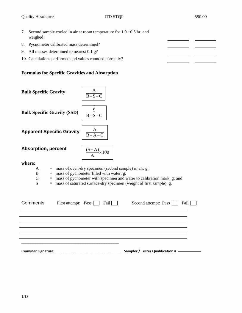
7. Second sample cooled in air at room temperature for 1.0 ±0.5 hr. and
weighed?
8. Pycnometer calibrated mass determined?
9. All masses determined to nearest 0.1 g?
10. Calculations performed and values rounded correctly?
Formulas for Specific Gravities and Absorption
Bulk Specific Gravity
Bulk Specific Gravity (SSD)
Apparent Specific Gravity
Absorption, percent
where: A = mass of oven-dry specimen (second sample) in air, g;
B = mass of pycnometer filled with water, g;
C = mass of pycnometer with specimen and water to calibration mark, g; and
S = mass of saturated surface-dry specimen (weight of first sample), g.
Comments: First attempt: Pass Fail Second attempt: Pass Fail
_________________________________________
Examiner Signature:_________________________________ Sampler / Tester Qualification #
CSB
A
CSB
A
CSB
S
CAB
A
100A
A)(S

Quality Assurance ITD STQP 590.00
1/13
PERFORMANCE EXAM CHECKLIST
Uncompacted Void Content of Fine Aggregate for AASHTO T 304 Participant Name:__________________________ Exam Date:_____________________
Record the symbols “P” for passing or “F” for failing on each step of the checklist.
Procedure Element (all test methods are AASHTO unless otherwise shown)
Sampling Trial 1 Trial 2
1. Sample obtained by one of the following:
(a) T 2 & T 248 (sampling, splitting and quartering)? ______ ______
or (b) From sieve analysis samples used for T 27? ______ ______
or (c) From aggregate extracted from a bituminous concrete specimen (T 308)? ______ ______
2. Methods A
(a) Sample washed over No. 100 or No. 200 sieve in accordance with T 11? ______ ______
(b) Sample dried and sieved into separate size fractions in accordance with T 27? ______ ______
(c) Necessary size fractions obtained from sieve analysis maintained in a dry
condition in separate containers for each size? ______ ______
Sample Preparation
Method A- Standard Graded Sample 1. Following quantities of aggregate that has been dried and sieved in accordance
with T 27 weighed out and combined? ______ ______
Individual Size Fractions Mass, g OK?
No. 8 to No. 16 44 ± 0.2
No. 16 to No. 30 57 ± 0.2
No. 30 to No. 50 72 ± 0.2
No. 50 to No. 100 17 ± 0.2
Total: 190 ± 0.2
Specific Gravity of Fine Aggregate
If bulk dry specific gravity of aggregate from the source is unknown, specific gravity
determined on material passing No. 4 sieve in accordance with IT 144. ______ ______
Procedure
1. Each test sample mixed with spatula until it appears to be homogeneous? ______ ______
2. Funnel stand apparatus with cylindrical measure, positioned in retaining pan? ______ ______
3. Finger used to block opening of funnel? ______ ______
4. Test sample poured into funnel? ______ ______
5. Material in funnel leveled with spatula? ______ ______

Quality Assurance ITD STQP 590.00
1/13
6. After funnel empties, excess heaped aggregate struck off from cylindrical measure
by single pass of spatula, with blade width vertical and using straight part of its
edge in light contact with top of measure? ______ ______
7. Care exercised to avoid vibration or any disturbance that could cause compaction
of aggregate into cylindrical measure? ______ ______
Note: After strike-off, measure may be tapped lightly to compact sample to make it easier to
transfer container to scale or balance without spilling any of the sample.
8. Adhering grains brushed from outside of container? ______ ______
9. Mass of cylindrical measure and contents determined to nearest 0.1 g? ______ ______
10. All aggregate particles retained for second test run? ______ ______
11. Sample from retaining pan and cylindrical measure recombined and procedure
repeated? ______ ______
12. Mass of empty measure recorded? ______ ______
13. Calculations performed properly? ______ ______
Formula for Calculation of Uncompacted Voids, percent
where:
U = uncompacted voids, percent;
V = volume of cylindrical measure to
nearest 0.1 mL;
F = net mass, g, of fine aggregate in
measure; and,
G = bulk dry specific gravity of fine
aggregate (Gsb)
Comments: First attempt: Pass Fail Second attempt: Pass Fail
Signature of Examiner__________________________________.
100 V
G
FV
U

Quality Assurance Idaho FOPs 580.00
1/13 ASTM D 4791
PERFORMANCE EXAM CHECKLIST
Flat Particles, Elongated Particles, or Flat and Elongated Particles in Coarse Aggregate Fop for ASTM D 4791
Participant Name:__________________________ Exam Date:_____________________ Record the symbols “P” for passing or “F” for failing on each step of the checklist. Procedure Element Trial 1 Trial 2
Sample Preparation
1. Sample obtained, mixed and reduced in accordance with AASHTO T 2 and AASHTO T 248 to approximately the amount required for testing? For combined samples fine portion (- # 4) removed?
2. Minimum dry sample mass meets requirements of Table 1?
Procedure
1. Sample sieved according to AASHTO T 27? 2. Each coarse aggregate size fraction present in amount of 10% or
more of original coarse sample reduced according to T 248 until approximately 100 particles obtained?
Flat and Elongated Particle Test:
3. Each particle in each size fraction tested and placed into one of two groups: (1) flat and elongated or (2) not flat and elongated?
4. Proportional caliper device positioned at proper ratio? ________ _______ 5. Larger opening set equal to particle length? 6. Particle is flat and elongated if the thickness can be placed in the
smaller opening?
8. Proportion of sample in each group determined by count or by mass, as required?
Calculation
1. Percentage of flat and elongated particles calculated to nearest 1% for each sieve size greater than No. 4?
2. When weighted average for sample is required, sieve sizes not tested (those representing less than 10% of sample) assumed to have same percentage of flat particles, elongated particles, or flat and elongated particles as the next smaller or the next larger size?
Or if both are present, is average for next smaller and larger sizes used?
Comments and Score: First Attempt: Pass Fail Second Attempt: Pass Fail Signature of Examiner:

Idaho Standards Section 520.00
1/08 Idaho IT-61
QUALIFICATION CHECKLIST FIELD VISCOSITY – IDAHO T 61
Record the symbols “P” for passing or “F” for failing on each step of the checklist.
Procedure Element
Sampling Trial 1 Trial 2
1. Sample taken using a valve:
a. Minimum of 4 L ( 1gal) allowed to flow before sample taken? 1a
b. Sample taken in clean 1 L ( 1 quart) wide mouth jar? 1b
2. Sample taken with Thief device.
a. Sample can immersed approximately to middle of tanker? 2a
b. Rubber stopper removed from can and sample taken from the middle of the tanker / tank? 2b
3. A portion of the sample transferred to a one (1) half pint plastic bottle and sealed with a stopper having a thermometer in the center? 3
Equipment
4. Temperature of the viscometer bath at 50ºC (122F)? 4
5. Viscosity tube clean and dry and cork installed? 5
Testing
6. Sample cooled to 51.7 ±0.3°C (125 ±0.5°F)? 6
7. Sample poured through a #20 sieve prior to entering the brass viscosity tube? 7
8. Enough sample poured into the tube to allow overflow into gallery? 8
9. Thermometer placed into tube and sample stirred slowly until testing temperature reached? 9
10. Thermometer withdrawn and excess in the overflow gallery siphoned out using a pipette without touching overflow rim? 10
11. Emulsified asphalt sample in viscometer immediately covered? 11
12. Cork pulled allowing the sample roll down the inside lip of the receiving flask? 12
13. Timer immediately started when cork is pulled? 13
14. Timer stopped when bottom of sample meniscus reaches graduation mark? 14
15. Test results reported to nearest 1 second on ITD-1045 form?
First Attempt: Pass Fail Second Attempt: Pass Fail
Comments:
Participant Name __________________________Exam Date ______________WAQTC#____________
Examiner’s Name: Signature
WAQTC #:_______________

Idaho Standards 520.00
9/98 Idaho IT-96
Idaho Standard Method of Test for
Determining the Percent of Coated Particles in
Bituminous Mixtures
Idaho IT-96-98
ITD Standard Specification Designation: Idaho T-96
1. Scope
1.1. The intent of this test is to establish a length of mixing time for the operation of a bituminous mixing plant. The method is based on the premise that the coarse aggregate is the most difficult and last to coat with asphalt. The aim is the least mixing time cycle that will produce a mix in which a minimum of 95% of the coarse aggregate particles are completely coated and all other specifications are satisfied.
2. Apparatus
2.1. Sieves – One (1) or more box-type screens of the size required for the mix.
2.1.1. For 1/2 in. (12.5 mm) maximum size aggregate, a No. 4 (4.75 mm) screen may be used.
2.1.2. For 1/2 to 1 in. (12.5 to 25.0 mm) maximum size aggregate, a 3/8 in. (9.5 mm) screen may be used.
2.1.3. For plus 1 in. (25.0 mm) maximum size aggregate, a 1/2 in. (12.5 mm) screen may be used.
2.2. Sample pan or trays.
2.3. Sample scoop or shovel.
2.4. Several sheets of manila paper, approximately 24 in. x 36 in. (600 mm x 900 mm).
2.5. Flood lamps, if required.
2.6. Stiff wire brush.
2.7. Small spatula.
2.8. Solvent and cleaning rags.

Idaho Standards 520.00
9/98 Idaho IT-96
3. Procedure
3.1. Permit the plant to operate at an established mixing time per batch (timed by stop watch).
3.2. Take a sufficiently large sample to obtain a coarse fraction count of from 200 to 500 coarse particles. This will generally require from 5 to 8 lb. (2.5 to 4 kg) of plant mix.
3.3. Three (3) separate samples shall be obtained from material produced under identical conditions, immediately after discharge from the pug mill.
3.4. Sieve the samples immediately, while they are still hot, through the proper size sieve. Do not overload the sieves. If necessary, sieve each sample in two (2) or three (3) operations. Shaking should be reduced to a minimum to prevent coating of uncoated particles.
4. Calculations
4.1. Spread the coarse particles on a sheet of manila paper and very carefully examine each particle. Any particle that has a spot (even pinpoint size) which is not coated, is counted as uncoated.
4.2. Group the counted particles, placing the uncoated ones on one side and the coated ones on the other side.
4.3. Counting in normal daylight is the best, but a flood light may be used if necessary.
4.4. The percentage of coated and uncoated particles is obtained by dividing each group by the total number of particles.
5. Report
5.1. In all samples, the number of coated particles must be 95% or above. If the count is below 95%, the mixing time shall be increased in increments and additional counts made until the count rises to 95% or more.

Idaho Standards 520.00
1/08 Idaho IT-99
QUALIFICATION CHECKLIST
DETECTION OF ANTI-STRIP ADDITIVE IN ASPHALT – IDAHO T 99
Record the symbols “P” for passing or “F” for failing on each step of the checklist.
Procedure Element Trial 1 Trial 2 General
1. All containers and or stir sticks were clean and chemical solutions were fresh. 1
Detection test by Color Method only
2. A control blank was performed. 2
3. 40ml of Reagent Isopropyl Alcohol or equivalent was used. 3
4. The asphalt mixture was heated on a hot plate. 4
5. Heating of sample was stopped before mixture became too dark. 5
6. The same amount of Bromophenol Blue Indicator was added to both mixtures. 6
7. Test results were accurately interpreted and recorded on the proper ITD form. 7
Comments: First Attempt: Pass Fail Second Attempt: Pass Fail
Testing Technician’s Name: WAQTC # : Date:
Examiner’s Name: Signature

Quality Assurance ITD STQP 590.00
1/13
PERFORMANCE EXAM CHECKLIST
Resistance to Deformation and Cohesion Of Bituminous Mixtures By Means Of Hveem
Apparatus For AASHTO T246
Participant Name: Exam Date: Record the symbols “P” for passing or “F” for failing on each step of the checklist.
Trial 1 Trial 2
Adjustment of Stabilometer
1. Base adjusted so that distance from bottom of upper tapered
ring to top of base is 89 mm (3.5 in.)?
2. Calibration cylinder inserted into stabilometer?
3. A horizontal pressure of 34.5kPa (5 psi) applied?
4. Turns indicator dial adjusted to zero?
5. Pump handle turned until the stabilometer dial reads 689kPa
(100 psi)?
6. Pump handle turned at approx. two turns per second?
7. Turns indicator dial reads 1.95 and 2.05 turns?
8. If not, is in the air in the cell adjusted and procedure repeated?
Resistance to Deformation 1. Test specimens mixed and compacted in accordance with T247?
2. Specimen brought to 60 ± 3°C (140 ± 5°F)?
3. Specimen transferred from mold to stabilometer by means of
the push-out device?
4. Tamped end of specimen is up?
5. Follower placed on top of specimen?
6. Vertical movement of press begun?
7. Speed of 1.3 mm/min (0.05 in./min)?
8. If locking shims used on spherical head of loading device,
shims removed prior to stabilometer test?
9. Stabilometer gauge readings recorded at vertical loads of 2.23,
4.45, 8.90, 13.4, 17.8, 22.3 and 26.7 kN (500, 1000, 2000,
3000, 4000, 5000, 6000 lbf)?
10. Vertical movement of press stopped at 26.7 kN (6000 lbf) load?
11. Vertical load immediately reduced to 4.45 kN (1000 lbf)?
12. Horizontal pressure adjusted to 34.5 kPa( 5 psi)?
Note: This will result in a further reduction of the vertical load and is normal.
13. Pump handle turned until the stabilometer dial reads 689
kPa (100 psi)?
14. Pump handle turned at approx. two turns per second?
15. Number of turns recorded as the displacement reading (D)?
16. Stabilometer value calculated correctly?
17. If height of specimen is not 64 ± 3 mm (2.5 ± 0.1 in.), is
stabilometer value corrected as shown below?

Quality Assurance ITD STQP 590.00
1/13
S = 22.2 Where: S = stabilometer value
Ph * D / (Pv – Ph) + 0.222 Ph = horizontal pressure
Pv = vertical pressure
D = displacement
COMMENTS: First attempt: Pass Fail Second attempt: Pass Fail
Signature of Examiner

Quality Assurance ITD STQP 590.00
1/13
PERFORMANCE EXAM CHECKLIST
Preparation of Test Specimens Of Bituminous Mixtures By Means of California Kneading
Compactor For AASHTO T247
Participant Name: Exam Date: Record the symbols “P” for passing or “F” for failing on each step of the checklist.
Trial 1 Trial 2
1. Estimated optimum bitumen content determined?
2. Tests conducted on 3 samples of different asphalt content: one
at estimated optimum, one above, and one below?
3. Aggregate separated into fractions?
4. Aggregate dried?
5. Aggregate recombined to 1200 g of specified grading?
6. Asphalt and aggregate at correct temperature when mixing
begins (see table below)?
Asphalt Grade AASHTO min. maximum
AC-2.5, AR 1000, or 200-300 Pen 107 (225) 121 (250)
AC-5, AR 2000, or 120-150 Pen 121 (250) 135 (275)
AC-10, AR 4000, or 85-100 Pen 135 (275) 149 (300)
AC-20, AR 8000, or 60-70 Pen 149 (300) 163 (325)
AC-40, AR 16000, or 40-50 Pen 149 (300) 163 (325)
7. Asphalt and aggregate rapidly and thoroughly mixed?
8. Mixture and molds brought to correct temperature [110°C
(230°F)] for paving grade asphalt?
9. Mold placed on mold holder and paper disk placed on bottom
of mold?
10. Shim placed under mold?
11. Mass of mixture for one specimen placed in preheated trough?
12. Mixture spread uniformly in trough?
13. One half of mixture pushed into mold with paddle?
14. Mixture rodded 20 times in center and 20 times around
periphery with preheated rod?
15. Rest of mixture placed in mold and rodding repeated?
16. Compactor foot heated?
17. Mold holder and mold placed in compactor?
18. Approx. 20 tamping blows at 1.7 MPa (250psi) applied?
19. Shim removed and mold tightening screw released?
20. 150 tamping blows at 3.4 MPa (500 psi) applied?
21. Mold and mixture placed in oven at 60°C (140°F):
(a) For 1 hour if compacted at 60°C (140°F) [liquid grade
asphalt]?
(b) For 1.5 hours if compacted at 110°C (230°F) [paving
grade asphalt]?

Quality Assurance ITD STQP 590.00
1/13
22. Followers inserted into mold?
23. Leveling-off load of 6.9 MPa (1000 psi) applied to specimen
using followers ad plungers?
24. Height measured to the nearest 0.25 mm (0.01 in.) in mold?
25. Specimen returned to 60°C (140°F) oven in mold in order to
obtain desired temp. for testing?
COMMENTS: First attempt: Pass Fail Second attempt: Pass Fail
Signature of Examiner

Quality Assurance IDAHO FOP’s 580.00
-5 AASHTO TP 68
PERFORMANCE EXAM CHECKLIST
Density of In-Place Hot Mix Asphalt (HMA) Pavement by Electronic Surface Contact Devices
FOP for AASHTO TP 68
Participant Name ______________________________ Exam Date ______________ Record the symbols “P” for passing or “F” for failing on each step of the checklist. Procedure Element Trial 1 Trial 2
1. Gauge turned on? _____ _____
2. Gauge calibrated using data from 6 inch cores? _____ _____
3. Test location selected away from any known sources of electromagnetic interference such as overhead high-tension power lines or large metal objects? _____ _____
4. The HMA surface is free of moisture, relitively flat, and smooth? _____ _____
5. Surface brushed clear of loose particles? _____ _____
6. Gauge placed firmly on HMA surface? _____ _____
7. Outline traced around base? _____ _____
8. Five (5) measurements taken per diagram # 1 and recorded? _____ _____
9. Average density calculated? _____ _____
10. Compaction calculated to 0.1%? _____ _____
Comments: First attempt: Pass Fail Second attempt: Pass Fail
Examiner Signature _______________________________WAQTC #:_______________
Examiner Signature _______________________________WAQTC #:_______________

Quality Assurance ITD STQP 590.00
1/13
PERFORMANCE EXAM CHECKLIST
BULK SPECIFIC GRAVITY AND DENSITY OF COMPACTED HOT MIX ASPHALT (HMA) USING AUTOMATIC VACUUM SEALING METHOD FOP FOR AASHTO T 331 Participant Name ______________________________ Exam Date ______________
Record the symbols “P” for passing or “F” for failing on each step of the checklist.
Procedure Element Trial 1 Trial 2
1. Mass of dry sample in air determined? _____ _____
a. Dried overnight at 125°F and at successive 2-hour intervals
to constant mass? _____ _____
b. Cooled in air to 77°± 9°F? _____ _____
c. Dry mass determined to 0.1g? _____ _____
d. Record initial dry mass as (A)? _____ _____
2. Bag weight recorded? _____ _____
a. Bag inspected for holes or irregularities? _____ _____
b. Bag weight recorded? _____ _____
3. Bag placed in vacuum chamber? _____ _____
4. Specimen placed in bag 25mm or 1in. from end of bag? _____ _____
5. Check that there are no wrinkles in the bag along the seal bar. _____ _____
6. Lid closed and lid retaining latch engaged? _____ _____
7. Once sealed remove the specimen carefully from chamber? _____ _____
8. Weight Specimen in bag in air?
a. Record mass to 0.1g? _____ _____
b. Subtract bag weight from total mass, record mass as (B). _____ _____
9. Sealed puck quickly placed in water bath at 77°± 1.8°F? _____ _____
a. From time vacuum lid opens to being submerged in water, not to exceed
1 min? _____ _____
b. Specimen fully submerged? _____ _____
c. Specimen not touching edges of water bath? _____ _____
d. Once scale stabilizes, record mass as (E). _____ _____
10. Bag removed from water bath? _____ _____
11. Sample removed from bag? _____ _____
Quality Assurance ITD STQP 590.00
1/13
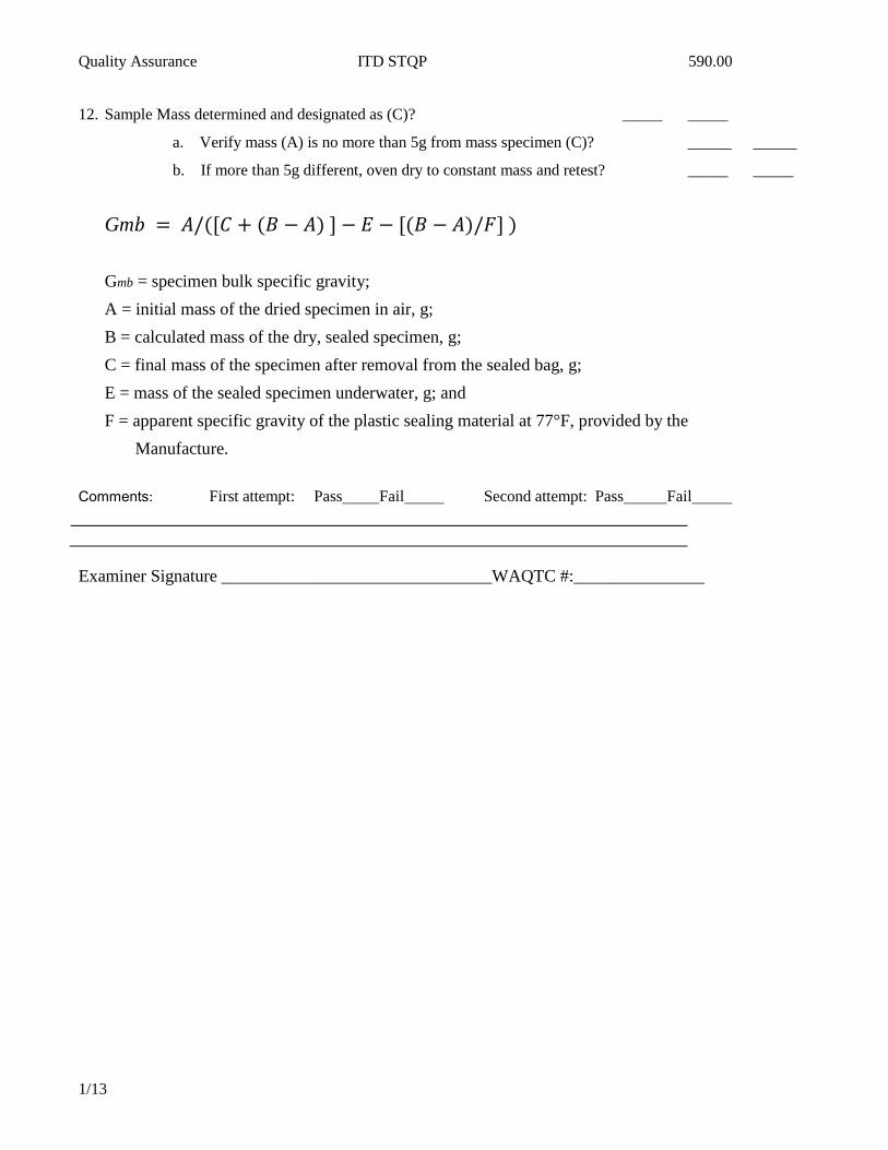
12. Sample Mass determined and designated as (C)? _____ _____
a. Verify mass (A) is no more than 5g from mass specimen (C)? _____ _____
b. If more than 5g different, oven dry to constant mass and retest? _____ _____
Gm
Gmb = specimen bulk specific gravity;
A = initial mass of the dried specimen in air, g;
B = calculated mass of the dry, sealed specimen, g;
C = final mass of the specimen after removal from the sealed bag, g;
E = mass of the sealed specimen underwater, g; and
F = apparent specific gravity of the plastic sealing material at 77°F, provided by the
Manufacture.
Comments: First attempt: Pass Fail Second attempt: Pass Fail
Examiner Signature _______________________________WAQTC #:_______________

WAQTC/IDAHO
WAQTC Standard Practice for
Field Sampling Bituminous Material after
Compaction (Obtaining Cores)
WAQTC TM 11 - 07
1 Scope
1.1 This method describes the process for removal of a core sample of compacted bituminous material from a pavement for laboratory testing. Cores may range in size from 2 in. to 12 in.
1.2 The values stated in SI units are to be regarded as the standard. The values given in parentheses
are for information only. 1.3 Safety—This method does not purport to address all of the safety problems associated with its
use. This test method involves potentially hazardous conditions.
2 Referenced Documents
2.1 WAQTC / AASHTO standard
WAQTC TM 8, In-Place Density of Bituminous Mixes using the Nuclear Density Gauge
WAQTC FOP for AASHTO T 166 / 275, Bulk Specific Gravity of Compacted Hot Mix Asphalt Mixtures Using Saturated Surface – Dry Specimens & Bulk Specific Gravity of Compacted Bituminous Mixtures Using Paraffin – Coated Specimens
T 331 Bulk Specific Gravity and Density of Compacted Asphalt Mixtures Using Automatic Vacuum Sealing Method
3 Significance and Use
3.1 Samples obtained in accordance with the procedure may be used for measuring pavement thickness and density. Additional testing may be performed as required by the agency.
3.2 When cores are used to determine nuclear gauge correlation, see WAQTC TM 8.
3.3 When cores are used to determine pavement density, the Bulk Specific Gravity (Gmb) is determined according to WAQTC FOP for AASHTO T 166 / T 275 or AASHTO T 331.

4 Apparatus
4.1 Coring Machine –A motor driven core machine shall be used to obtain the sample. The device shall be capable of obtaining a core to the full depth of the bituminous material.
4.2 Core Bit – The cutting edge of the core drill bit shall be of hardened steel or other suitable material with diamond chips embedded in the metal cutting edge. The core barrel inside diameter shall be as specified.
4.3 Separation Equipment –A saw or other method(s) that provides a clean smooth plane representing the layer to be tested.
4.4 Retrieval Device – A device for removing core samples that will preserve the integrity of the core.
5 Material
5.1 Cooling agent such as: water, ice, dry ice, or liquid nitrogen.
6 Test Site Location
6.1 The number of cores obtained shall be determined by the test procedure or agency requirements.
6.2 Core location(s) shall be determined by the agency.
7 Procedure
7.1 For freshly compacted bituminous materials, the core shall be taken when the material has had sufficient amount of time to cool to prevent damage to the core.
7.2 To accelerate the coring process, a cooling agent may be used.
7.3 Place the coring machine such that the core bit is over the selected location.
7.4 Provide a means such as water or air to aid in the removal of cuttings and to minimize the generation of heat caused by friction.
7.5 Keep the core bit perpendicular to the bituminous surface during the coring process.
7.6 Apply constant downward pressure on the core bit. Failure to apply constant pressure, or too much pressure, may cause the bit to bind or distort the core.
7.7 Continue the coring operation until the desired depth is achieved.
7.8 Use a retrieval device to obtain the core.
7.9 Clearly label the core.

WAQTC/IDAHO
8 Filling Core Holes
8.1 The hole made from the coring operation shall be filled with a material that will not become dislodged.
9 Transporting
9.1 Transport cores on a smooth surface, top side down in a container(s) that prevents damage from jarring, rolling or impact with any object.
9.2 Prevent cores from freezing or from excessive heat, 54° C (130F), during transport.
Note 1— In extreme ambient temperature conditions, an insulated container should be used during transport.
10 Layer Separation
10.1 Separate two or more pavement courses, lifts, or layers; by the use of separation equipment on the
designated lift line. Note 2— Lift lines are often more visible by rolling the core on a flat surface.
11 Thickness Determination
11.1 Measure the thickness of the designated lift to 3 mm (0.10 in). Three or more measurements shall be taken around the lift and averaged.
12 Report
12.1 Core information shall be reported on standard agency forms. Include the following information:
13.1.1. Date
13.1.2. Coring Location
13.1.3. Lift / Layer being evaluated
13.1.4. Material Type
13.1.5. Average Thickness.

Quality Assurance 590.00
1/13
PERFORMANCE EXAM CHECK LIST
DETERMINING THE PLASTIC LIMIT AND PLASTICITY INDEX OF SOILS AASHTO T-90
Participant Name: Exam Date: Record the symbols “P” for passing or “F” for failing on each step of the checklist: Procedure Elements: Trial#1 Trial#2
1. Inspect and clean apparatus. Apparatus include mixing dish, spatula, rolling surface, moisture containers with lids, balance readable to 0.01g and a drying oven. All apparatus should be clean dry and within specifications. Moisture containers and their lids will be weighed and recorded before each test. _____ _____
2. Prepare sample . As per AASHTO T-87 or AASHTO T-146. This test requires approximately 20g of material. Material for this test can be obtained from material used for AASHTO T-89. _____ _____
3. Adjustment of moisture content. Moisture content shall be such that the material can be shaped into a ball and is not sticky. Use distilled or demineralized water only. _____ _____
4. Roll sample to 3.0 mm (approx. 1/8”). Take approximately 8g of the 20g sample and separate into1.5– 2.0 gram increments. Roll on a ground surface with just enough pressure to make a thread of uniform diameter for it’s entire length. A rolling rate of 80 to 90 strokes/minute shall be used. When the diameter of the thread becomes 3.0 mm (approx. 1/8”) break thread into 6 to 8 pieces then make a ball and repeat process. There is a 2 minute time to get from a ball down to 3.0 mm (approx. 1/8”). _____ _____
5. Re-roll until thread breaks or crumbles. Repeat step # 4 until thread breaks into a series of
segments 6.4 mm (1/4”) to 9.5 mm (3/8”) in length. The sample must be rolled to 3.0 mm (1/8”) at least once before it breaks or crumbles, if failure occurs on the first try add moisture and repeat steps. Do not attempt to produce failure at 3.0 mm (1/8”) in diameter. _____ _____
6. Collect crumbled particles. Using the spatula, gather all portions of the crumbled particles into a suitable container, cover immediately and determine the mass to the nearest 0.01g. _____ _____
7. Remove cover and place in oven at 1105 C (2309 F) and dry to constant mass. When removing sample from the drying oven cover immediately. _____ _____
8. Determine moisture content. After drying to a constant mass, cool and determine the mass to the nearest 0.01g and calculate moisture content to the nearest 0.1%. _____ _____
9. Report Plastic Limit. Plastic Limit is recorded as the nearest whole number . _____ _____
10. Determine Plasticity Index (PI). Calculate the Plasticity Index of the soil as the difference between
its Liquid Limit and its Plastic Limit. Example: LL – PL = PI, the result is reported to the nearest whole number. _____ _____
COMMENTS: First Attempt : Pass Fail Second Attempt: Pass Fail
Examiner Signature:_________________________________________ Sampler / Tester Qualification #
Examiner Signature:_________________________________________ Sampler / Tester Qualification #

Quality Assurance ITD STQP 590.00
1/13
PERFORMANCE EXAM CHECK LIST
DETERMINING THE LIQUID LIMIT OF SOILS AASHTO T-89 (METHOD “B” ONE POINT)
Participant Name: Exam Date: Record the symbols “P” for passing or “F” for failing on each step of the checklist: Procedure Elements: Trial#1 Trial#2 1. Prepare sample. Using AASHTO T-87 or AASHTO T-146. This test requires a minimum of
50g of minus # 40 (0.425 mm) material. _____ _____
2. Inspect and adjust test apparatus. Apparatus includes liquid limit device, porcelain mixing dish, spatula, grooving tool, gauge for cup height drop, containers with lids, balance readable to the hundredth and a drying oven. All apparatus shall be clean, dry and within specifications. Moisture containers and lids will be weighed and recorded before each test. Check the drop height on the liquid limit device using the gauge and a piece of tape and adjust as necessary. _____ _____
3. Adjust sample moisture and mix. Use distilled or demineralized water only Add 8 to 10 ml
of water to material and mix thoroughly, approximately 5 to 10 minutes. Moisture may then be adjusted by adding increments of 1 to 3 ml of water and mixing thoroughly, approximately 1 minute, or by air drying while mixing and kneading. Moisture may not be adjusted by adding dry soil to the moistened sample. Cover the sample and allow to season for 30 minutes. _____ _____
4. Spread sample into cup of device. Remix sample and spread above the spot where cup rests on the base. The top surface should be as level as possible and 10 mm in thickness at it’s maximum depth. Use as few strokes as possible, do not entrap air into the sample. Return excess material to the mixing dish. _____ _____
5. Cut groove into the sample. Cut groove through the center of the sample, perpendicular to the
hinge pin of the cup. Use as few strokes as possible. Up to 6 strokes may be used, only the last stroke should touch the bottom of the cup. _____ _____
6. Turn the device on and count the taps. Count the number of taps required to close the groove for a length of approx. ½” (13 mm). If sample slides instead of flowing, add water, remix and repeat test. If problem re-occurs discontinue test and note. _____ _____
7. Repeat steps 3 through 6 until the grove closes with a range of 22 and 28 taps. Return
remaining soil in the brass cup to the mixing dish with something other than the spatula. Apparatus shall be cleaned and dried between tests. Adjustment of moisture shall follow the guidelines in step 3. _____ _____
8. Take sample for moisture content determination. Using the spatula, take a slice of the sample
the width of the spatula at the point of closure. The slice shall extend from edge to edge of the soil and perpendicular to the groove for the full depth of the sample. Place the moisture sample in a suitable container, cover immediately, determine the mass to the nearest 0.01g and record immediately. _____ _____
9. Remove cover, place in oven at 1105 C (2309 F) and dry to a constant mass. When removing the sample from the oven to determine constant mass cover immediately. _____ _____
OVER
Quality Assurance ITD STQP 590.00
1/13
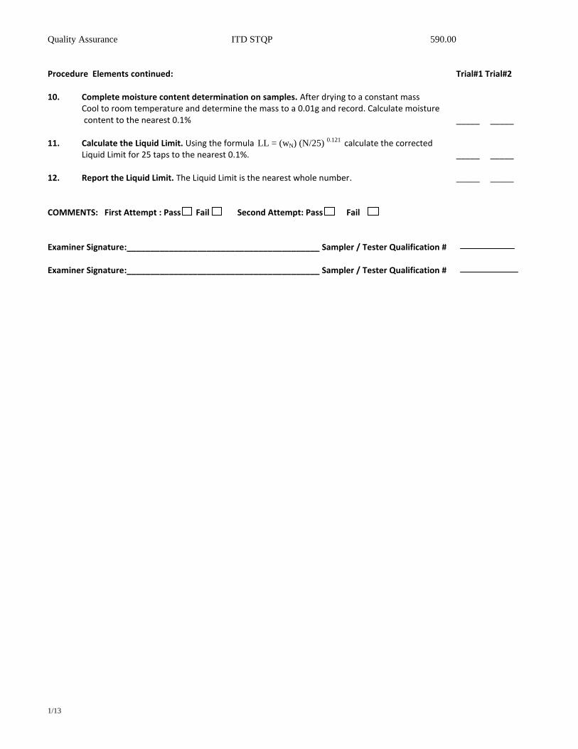
Procedure Elements continued: Trial#1 Trial#2 10. Complete moisture content determination on samples. After drying to a constant mass
Cool to room temperature and determine the mass to a 0.01g and record. Calculate moisture content to the nearest 0.1% _____ _____
11. Calculate the Liquid Limit. Using the formula LL = (wN) (N/25)
0.121 calculate the corrected Liquid Limit for 25 taps to the nearest 0.1%. _____ _____
12. Report the Liquid Limit. The Liquid Limit is the nearest whole number. _____ _____
COMMENTS: First Attempt : Pass Fail Second Attempt: Pass Fail Examiner Signature:_________________________________________ Sampler / Tester Qualification # Examiner Signature:_________________________________________ Sampler / Tester Qualification #

Quality Assurance 590.00
1/13
PERFORMANCE EXAM CHECK LIST
DETERMINING THE SPECIFIC GRAVITY OF SOILS
AASHTO T-100
Participant Name: Exam Date: Record the symbols “P” for passing or “F” for failing on each step of the checklist: Procedure Elements: Trial#1 Trial#2
1. Sample obtained? _____ _____
2. Flask filled three quarters with distilled water? _____ _____
3. Entrapped air removed? _____ _____
4. Vacuum 100mm or less? _____ _____
5. Flask agitated gently for the allowed amount of time? ______ _____
a. Oven dried sample 2 – 4 hours ______ _____
b. Low plasticity 4 – 6 hours ______ _____
c. High plasticity containing moisture 6 -8 hours _____ _____
6. Pycnometer filled to calibration mark? _____ _____
7. Pycnometer mass determined? _____ _____
8. Temperature determined? _____ _____
Specific Gravity, Tx / Tx = Wo / [Wo + (Wa – Wb)]
Specific Gravity, Tx / 20oC = (Specific Gravity, Tx/Tx) x K
Where:
Tx = temperature of the contents of the Pycnometer when mass Wb was determined, in degrees
Celsius;
Wo = mass of sample of oven-dried soil in grams
Wa = mass of pycnometer filled with water at temperature Tx in grams
Wb = mass of pycnomter filled with water and soil at temperature Tx, in grams
K = Correction Factor = (Rel. Density of Water at Tx / Rel. Density of Water at 20oC)
COMMENTS: First Attempt : Pass Fail Second Attempt: Pass Fail
Examiner Signature:_________________________________________ Sampler / Tester Qualification #
Examiner Signature:_________________________________________ Sampler / Tester Qualification #

Quality Assurance 590.00
1/13
PERFORMANCE EXAM CHECK LIST
SAMPLING & FABRICATION OF 2” (50 – MM) CUBE SPECIMENS USING GROUT (NON-SHRINK) MORTAR AASHTO TP 83
Participant Name: Exam Date: Record the symbols “P” for passing or “F” for failing on each step of the checklist: Procedure Elements: Trial#1 Trial#2 1. Obtain Sample. Use AASHTO T-141 for 1 yd
3 or more or for less than 1 yd3 sample from
discharge after remixing takes place. _____ _____
2. Inspect and adjust test apparatus. Apparatus includes mold assembly, tamper, trowel, watertight container. _____ _____
3. Mold portion attached to bottom plate and joints are water tight. Use of a light coating of
non water-soluble grease is allowed. _____ _____
4. Place a 1”(approximately 1/2 the depth of the mold) layer of Grout or non-shrink mortar into the mold. Grout or mortar shall be placed in all compartments. _____ _____
5. Consolidate the mix. The mix shall be consolidated depending on the consistency,
either plastic or fluid. _____ _____ 6. Plastic mixes: tamp lift in 4 rounds, 8 tamps per round, for a total of 32 tamps in 10 seconds
with rubber tamper. Rounds 1 and 3 and 2 and 4 shall be the same. _____ _____
7. Fluid Mixes: puddle the lift 5 times with gloved finger. _____ _____
OVER

Quality Assurance 590.00
1/13
Procedure Elements continued: Trial#1 Trial#2
8. Place the second lift into all of the mold compartments and consolidate: Slightly overfill.
Consolidate in same fashion as first lift. After consolidation material should extend slightly above the top of the mold. Push any grout forced out onto the top of the mold back onto the compartment with a trowel. _____ _____
8. Strike off the surface. Using the trowel draw the flat side with the leading edge slightly
raised once across the top of each cube at right angles to the length of the mold. Then draw the flat trailing edge of the trowel, with leading edge slightly raised,) once lightly along the length of the mold. Cut off the mortar to a plane surface flush with the top of the mold by drawing the straight edge of the trowel (held nearly perpendicular to the mold) with a sawing motion over the length of the mold. The material shall be flush with the top of the mold. _____ _____
9. Immediately secure the top plate to the molds. _____ _____ 10. Molds properly stored: Cover with wet burlap, towels, or rags, seal it in a plastic sack in a
level location out of direct sunlight, and record the time. These samples shall remain undisturbed and protected from freezing or overheating for a period of 24 ± 4 hours. _____ _____
COMMENTS: First Attempt : Pass Fail Second Attempt: Pass Fail
Examiner Signature:_________________________________________ Sampler / Tester Qualification # Examiner Signature:_________________________________________ Sampler / Tester Qualification #