section 5: standards for storm drainage systems
TRANSCRIPT
SECTION 5: Standards for Storm Drainage Systems
5. Storm D
rainage System

2009 CITY OF KENT DESIGN & CONSTRUCTION STANDARDS
September 2009
5-1
5.0 STANDARDS FOR STORM DRAINAGE SYSTEMS
5.1 GENERAL
5.1.A Design Standards
Drainage facilities shall be designed in accordance with the City of Kent Surface Water Design Manual (KSWDM).
5.1.B Specifications
Materials, construction, and testing are specified in Section 7-04 of the WSDOT Standard Specifications.
5.1.C Conflicts
Where technical conflicts may occur between this document and the KSWDM, these Standards shall govern.
5.2 EASEMENTS AND RIGHTS-OF-WAY
Permanent on-site easements for access, maintenance, and construction are required in accordance with KSWDM Section 4.1 for all storm drain extensions located outside of public right-of-way.
Private improvements such as buildings, fences, garages, carports, retaining walls, utilities, signs, light standards, etc., are not allowed in public easements and rights-of-way. Where an encroachment occurs, the Developer shall remove and relocate the conflicting private improvement immediately upon direction from the Engineer.
Easements shall be accessible for construction equipment normally used for the operation and maintenance of the facility. Cross slopes exceeding 5 percent will require a deviation approval of the Engineer.
5.3 STORM WATER SYSTEM AND CULVERTS
5.3.A Pipe Bedding
Pipe bedding shall be placed under and all around the pipe meeting the requirements of gravel backfill for pipe zone bedding per Section 9-03.12(3) of the WSDOT Standard Specifications, latest edition. It shall be compacted in layers around the pipe and to a sufficient height above the pipe to adequately support and protect the pipe to 95 percent compaction ASTM D-1557. See WSDOT Standard Plans and Standard Plan 3-22.

2009 CITY OF KENT DESIGN & CONSTRUCTION STANDARDS
September 2009
5-2
5.3.B Access Roads
Access roads to each catch basin and manhole are required for maintenance. Access and/or maintenance roads (where required) shall be 15’ wide and have a minimum inside turning radius of 45’. Access and/or maintenance roads will require an approved all-weather surface, and shall be designed to support an HS-20 vehicle load to support construction equipment and loads. The profile of an access road shall not exceed 15 percent. Access roads with grades exceeding 12 percent shall be paved. Whenever an easement or right-of-way is fenced, a gate shall be installed matching the width of the easement and a City lock must be placed in “series”.
All access roads longer than 150’ from the nearest face of curb or edge of pavement of the connecting street shall have an approved hammerhead turnaround per Standard Plan 6-21 or shall be looped to connect back to a public street.
5.3.C Casings:
Where a storm water line passes under or through a retaining wall or is attached to a bridge structure, the pipe shall be cased in steel pipe at least 4” larger than the largest outer diameter of the bell or joint of the storm water line. No pipe joints will be allowed within the casing, except on bridge structures or unless otherwise approved by the Engineer. The casing shall extend on either side of the wall a distance equal to the highest height of the retaining wall at the wall penetration, plus 4’. All voids within the casing shall be filled with blown sand except on bridge structures. Casing spacers shall be Cascade Waterworks Manufacturing Company stainless steel casing spacers or approved equal. The casing spacers shall be installed such that the storm water line is centered and restrained within the casing and spaced such that a uniform profile grade will be maintained within the casing.
5.4 CATCH BASIN LOCATIONS AND JUNCTIONS
5.4.A Catch Basins
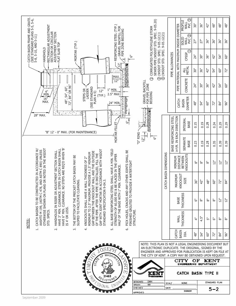
Catch basins, rather than inlets, shall be used to collect storm water from street surfaces, unless otherwise approved by the Engineer. See Standard Plans 5-1 and 5-2.
5.4.B Connections to Pipe Systems
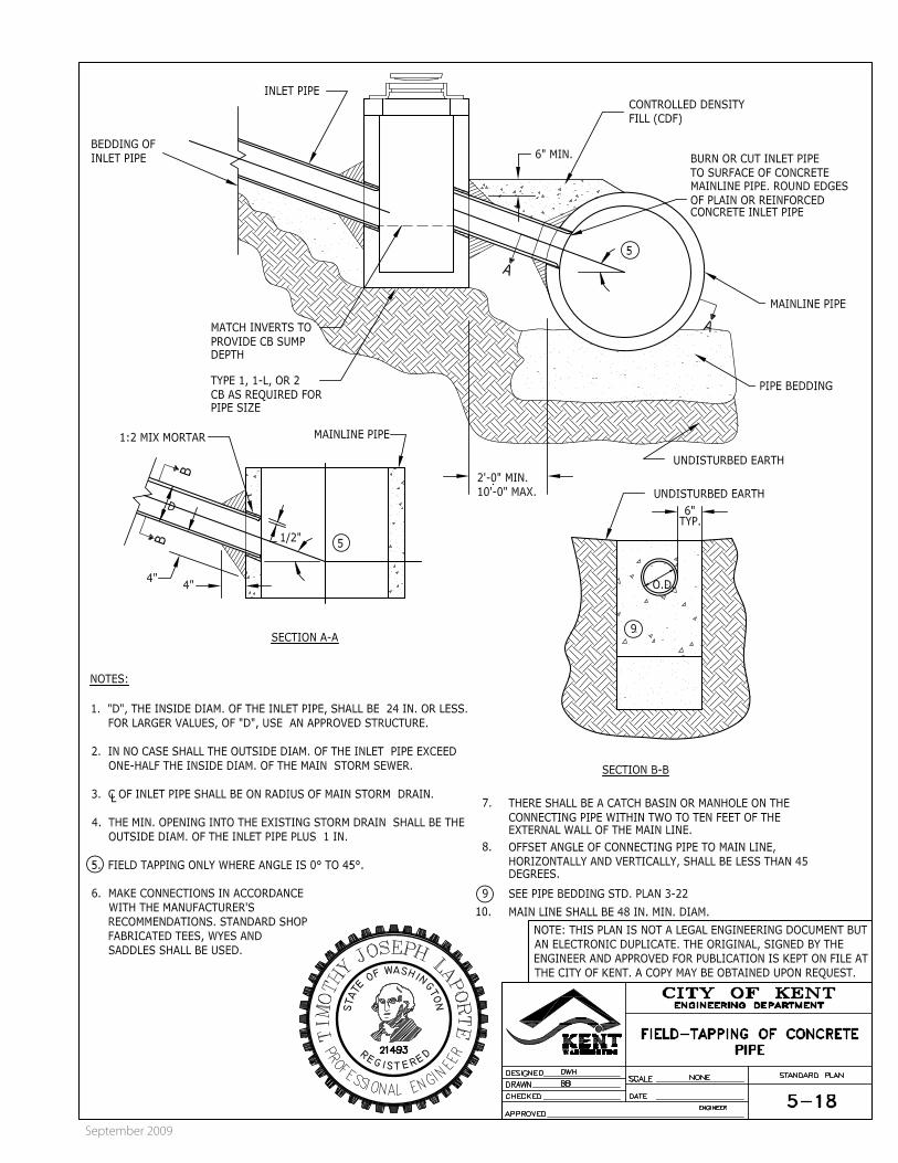
Connections to pipe systems may be made without placing a catch basin or manhole on the mainline only nin accordance with Standard Plan 5-18. All other connections shall be made at catch basins or manholes.
2009 CITY OF KENT DESIGN & CONSTRUCTION STANDARDS
September 2009
5-3
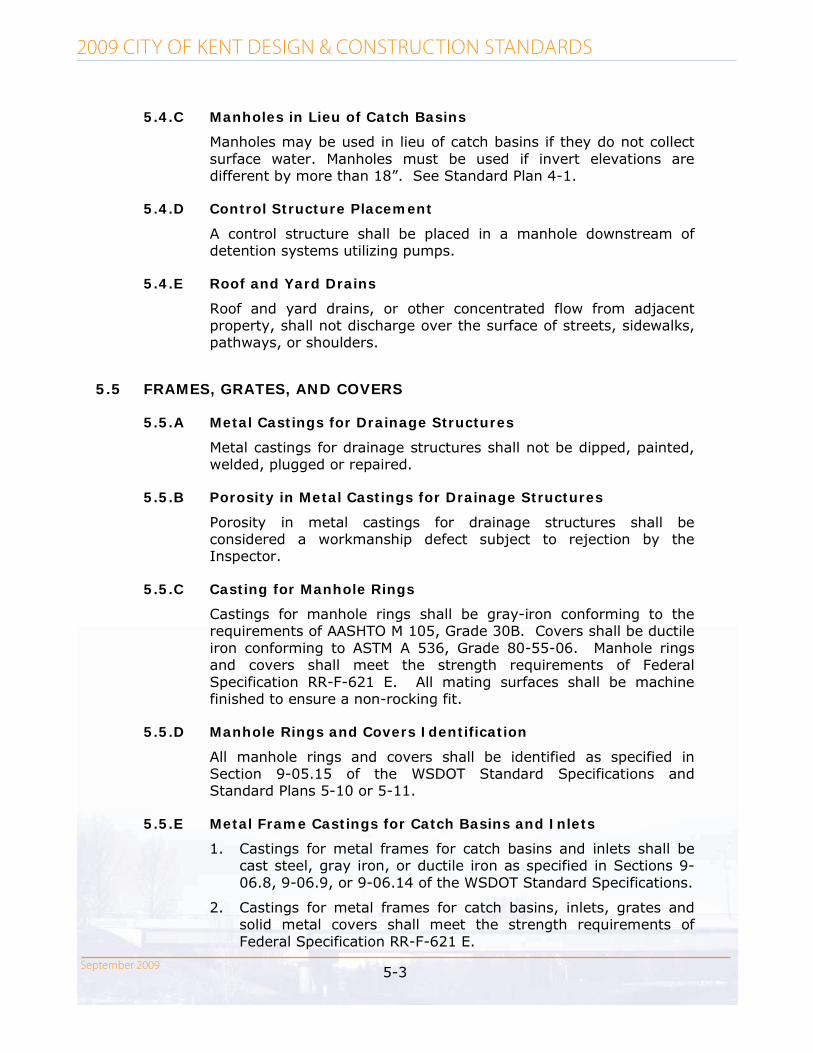
5.4.C Manholes in Lieu of Catch Basins
Manholes may be used in lieu of catch basins if they do not collect surface water. Manholes must be used if invert elevations are different by more than 18”. See Standard Plan 4-1.
5.4.D Control Structure Placement
A control structure shall be placed in a manhole downstream of detention systems utilizing pumps.
5.4.E Roof and Yard Drains
Roof and yard drains, or other concentrated flow from adjacent property, shall not discharge over the surface of streets, sidewalks, pathways, or shoulders.
5.5 FRAMES, GRATES, AND COVERS
5.5.A Metal Castings for Drainage Structures
Metal castings for drainage structures shall not be dipped, painted, welded, plugged or repaired.
5.5.B Porosity in Metal Castings for Drainage Structures
Porosity in metal castings for drainage structures shall be considered a workmanship defect subject to rejection by the Inspector.
5.5.C Casting for Manhole Rings
Castings for manhole rings shall be gray-iron conforming to the requirements of AASHTO M 105, Grade 30B. Covers shall be ductile iron conforming to ASTM A 536, Grade 80-55-06. Manhole rings and covers shall meet the strength requirements of Federal Specification RR-F-621 E. All mating surfaces shall be machine finished to ensure a non-rocking fit.
5.5.D Manhole Rings and Covers Identification
All manhole rings and covers shall be identified as specified in Section 9-05.15 of the WSDOT Standard Specifications and Standard Plans 5-10 or 5-11.
5.5.E Metal Frame Castings for Catch Basins and Inlets
1. Castings for metal frames for catch basins and inlets shall be cast steel, gray iron, or ductile iron as specified in Sections 9-06.8, 9-06.9, or 9-06.14 of the WSDOT Standard Specifications.
2. Castings for metal frames for catch basins, inlets, grates and solid metal covers shall meet the strength requirements of Federal Specification RR-F-621 E.

2009 CITY OF KENT DESIGN & CONSTRUCTION STANDARDS
September 2009
5-4
5.5.F Metal Grates and Covers for Catch Basins and Inlets
Castings for grates and solid metal covers for catch basins and inlets shall be cast steel or ductile iron as specified in Sections 9-06.8 or 9-06.14 of the WSDOT Standard Specifications. The foundry name and material designation shall be embossed on the top of the grate. The material shall be identified as “CS” for cast steel, and “DUC” or “DI” for ductile iron and shall be located near the manufacturer’s name. See Standard Plans 5-4 through 5-9.
5.5.G Grate and Cover Seating
Grates and covers shall be seated properly to prevent rocking, including the replacement of existing covers with solid metal covers.
5.5.H Vaned Grates
Unless otherwise specified, vaned grates shall be used with standard frame in the traveled way, gutter, or shoulder. Vaned grates shall not be located within crosswalks. See Standard Plans 5-4 through 5-6.
5.5.I Rolled Curbs
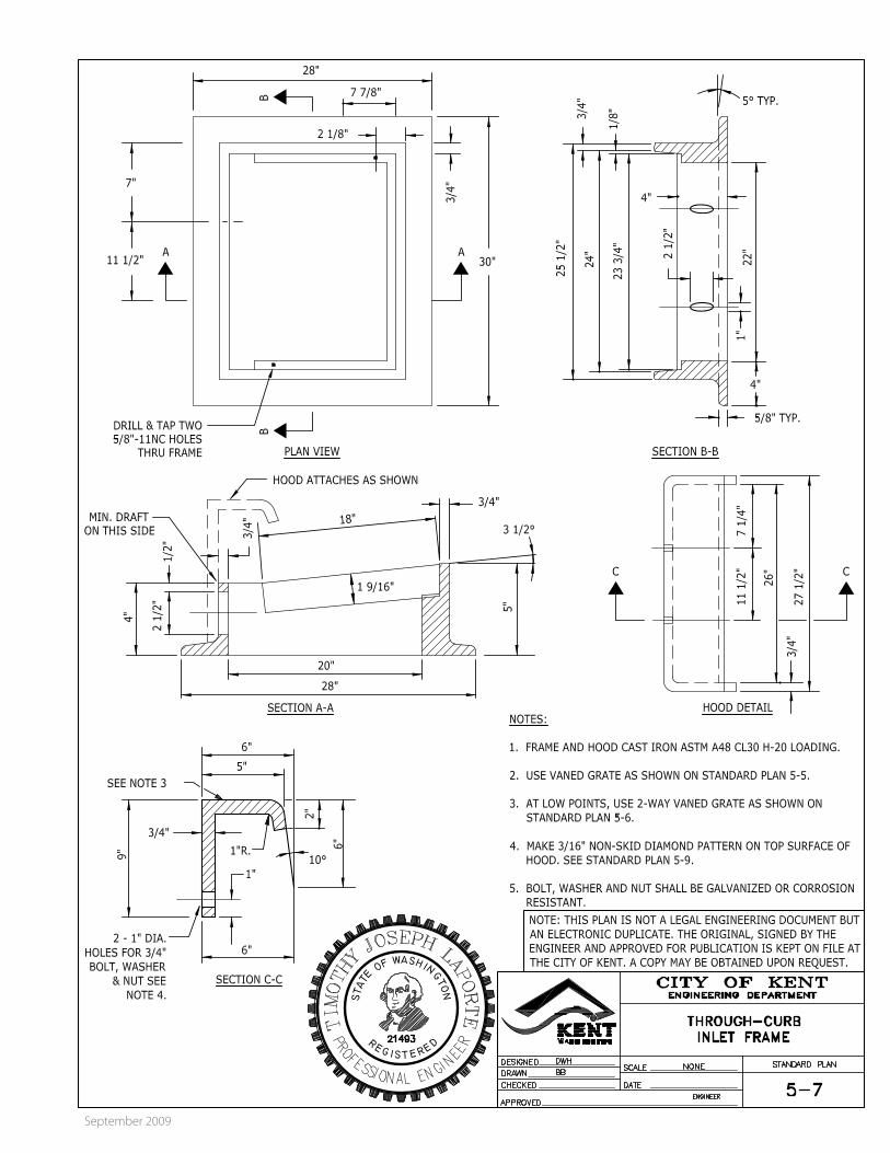
Use rolled curb frame and grates along rolled curbs. See Standard Plan 5-7.
5.5.J Runoff Collection in Catch Basins
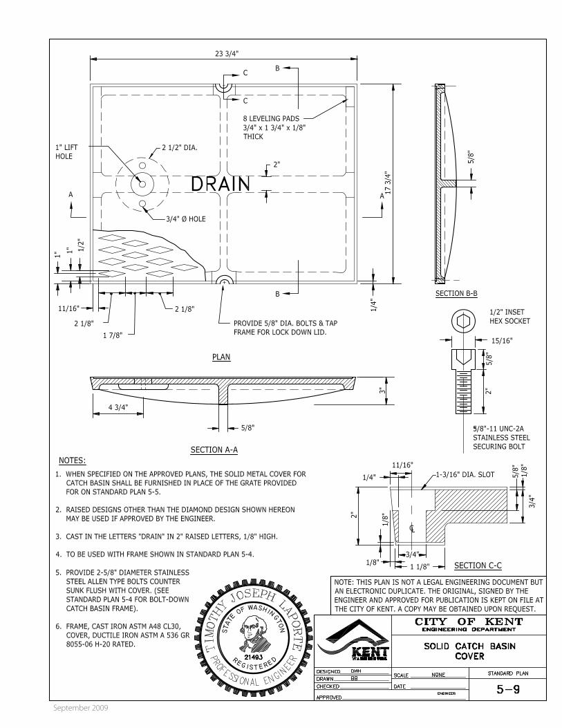
New catch basins that do not collect runoff shall use solid locking covers. Existing catch basins, which no longer collect runoff, shall have their frame and grates replaced with new frames and solid covers. See Standard Plan 5-9.
5.5.K Locking Drain Covers and Grates
All storm drain covers and grates shall be locking. All control structures storm drain covers shall be locking regardless of their location.
5.5.L Fencing for Stormwater Facilities
All on-site detention ponds located within commercial or residential zones shall have fencing 6’ high. See Standard Plans 5-22 & 5-23.
5.6 TELEVISION INSPECTION
All new storm drain extensions will be TV camera inspected by the City prior to acceptance.
Prior to TV camera inspection:
1. Storm drain lines and catch basins must be cleaned
2009 CITY OF KENT DESIGN & CONSTRUCTION STANDARDS
September 2009
5-5
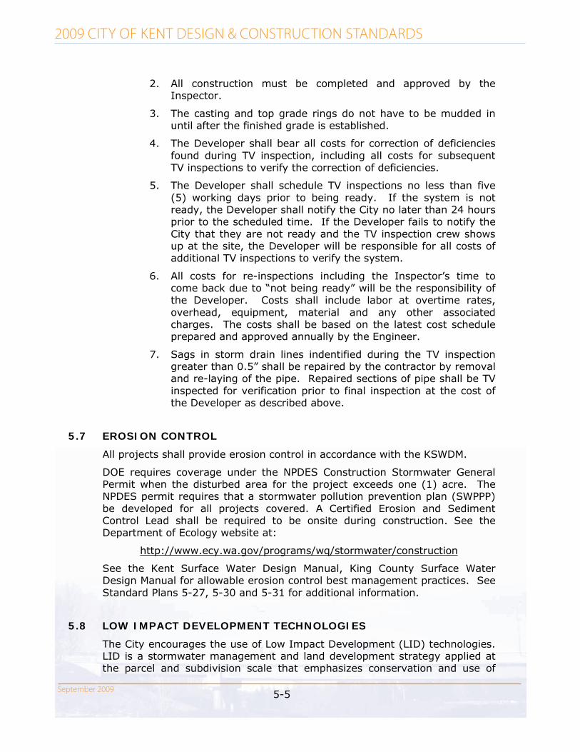
2. All construction must be completed and approved by the Inspector.
3. The casting and top grade rings do not have to be mudded in until after the finished grade is established.
4. The Developer shall bear all costs for correction of deficiencies found during TV inspection, including all costs for subsequent TV inspections to verify the correction of deficiencies.
5. The Developer shall schedule TV inspections no less than five (5) working days prior to being ready. If the system is not ready, the Developer shall notify the City no later than 24 hours prior to the scheduled time. If the Developer fails to notify the City that they are not ready and the TV inspection crew shows up at the site, the Developer will be responsible for all costs of additional TV inspections to verify the system.
6. All costs for re-inspections including the Inspector’s time to come back due to “not being ready” will be the responsibility of the Developer. Costs shall include labor at overtime rates, overhead, equipment, material and any other associated charges. The costs shall be based on the latest cost schedule prepared and approved annually by the Engineer.
7. Sags in storm drain lines indentified during the TV inspection greater than 0.5” shall be repaired by the contractor by removal and re-laying of the pipe. Repaired sections of pipe shall be TV inspected for verification prior to final inspection at the cost of the Developer as described above.
5.7 EROSION CONTROL
All projects shall provide erosion control in accordance with the KSWDM.
DOE requires coverage under the NPDES Construction Stormwater General Permit when the disturbed area for the project exceeds one (1) acre. The NPDES permit requires that a stormwater pollution prevention plan (SWPPP) be developed for all projects covered. A Certified Erosion and Sediment Control Lead shall be required to be onsite during construction. See the Department of Ecology website at:
http://www.ecy.wa.gov/programs/wq/stormwater/construction
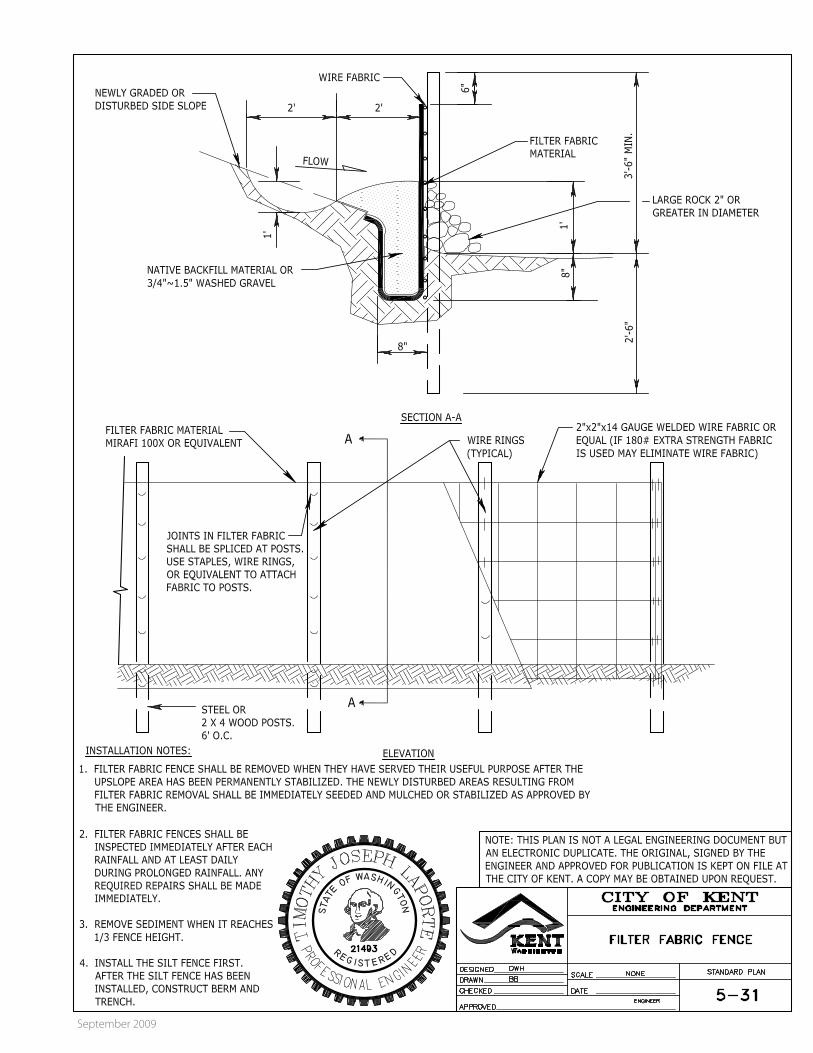
See the Kent Surface Water Design Manual, King County Surface Water Design Manual for allowable erosion control best management practices. See Standard Plans 5-27, 5-30 and 5-31 for additional information.
5.8 LOW IMPACT DEVELOPMENT TECHNOLOGIES
The City encourages the use of Low Impact Development (LID) technologies. LID is a stormwater management and land development strategy applied at the parcel and subdivision scale that emphasizes conservation and use of

2009 CITY OF KENT DESIGN & CONSTRUCTION STANDARDS
September 2009
5-6
existing natural site features integrated with engineered small scale hydrologic controls to more closely mimic pre-development functions. The goal of LID is to prevent measurable harm to streams, lakes, wetlands, and other natural aquatic systems from residential, commercial, or industrial development sites.
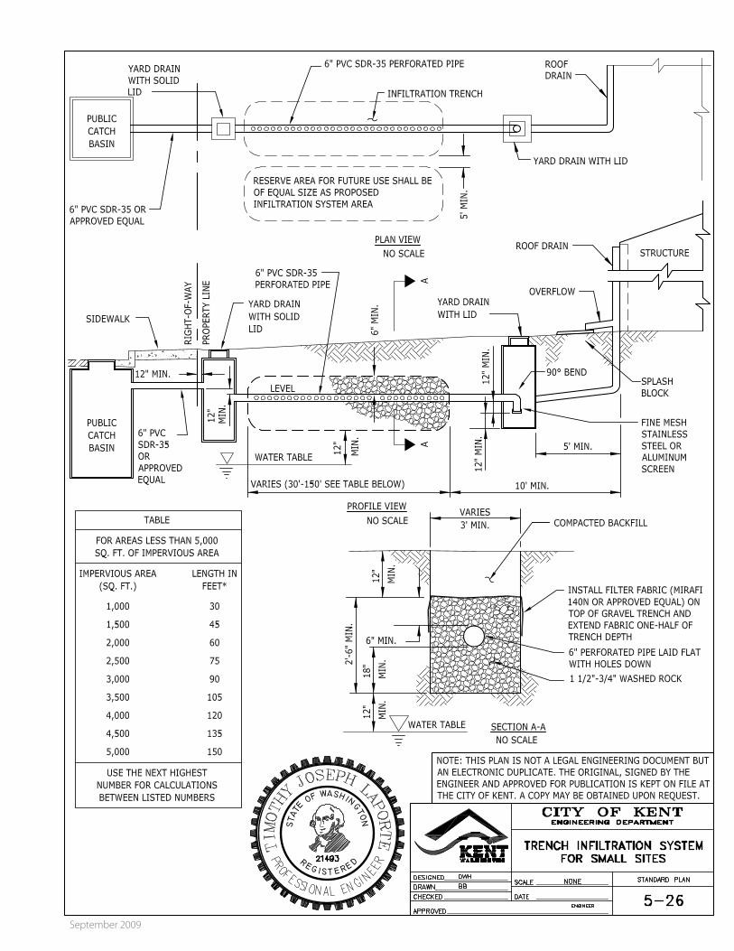
LID technologies include stormwater best management practices designed to reduce runoff from development using infiltration, evapotranspiration, or stormwater reuse. Examples of LID technologies include trees, preservation of native vegetation, porous pavement, bio-retention swales, infiltration systems, dry wells, cisterns, and rain gardens. Examples of these technologies are provided in the 2005 King County Surface Water Design Manual.
5-7
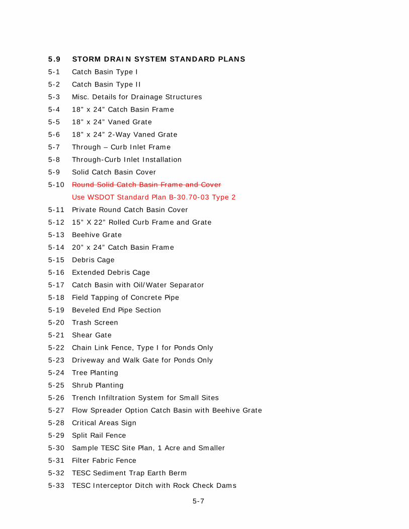
5.9 STORM DRAIN SYSTEM STANDARD PLANS
5-1 Catch Basin Type I
5-2 Catch Basin Type II
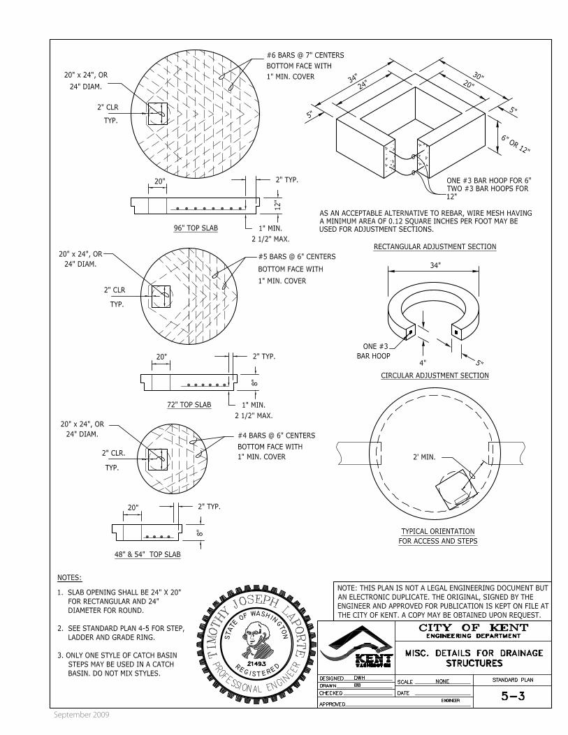
5-3 Misc. Details for Drainage Structures
5-4 18” x 24” Catch Basin Frame
5-5 18” x 24” Vaned Grate
5-6 18” x 24” 2-Way Vaned Grate
5-7 Through – Curb Inlet Frame
5-8 Through-Curb Inlet Installation
5-9 Solid Catch Basin Cover
5-10 Round Solid Catch Basin Frame and Cover
Use WSDOT Standard Plan B-30.70-03 Type 2
5-11 Private Round Catch Basin Cover
5-12 15” X 22” Rolled Curb Frame and Grate
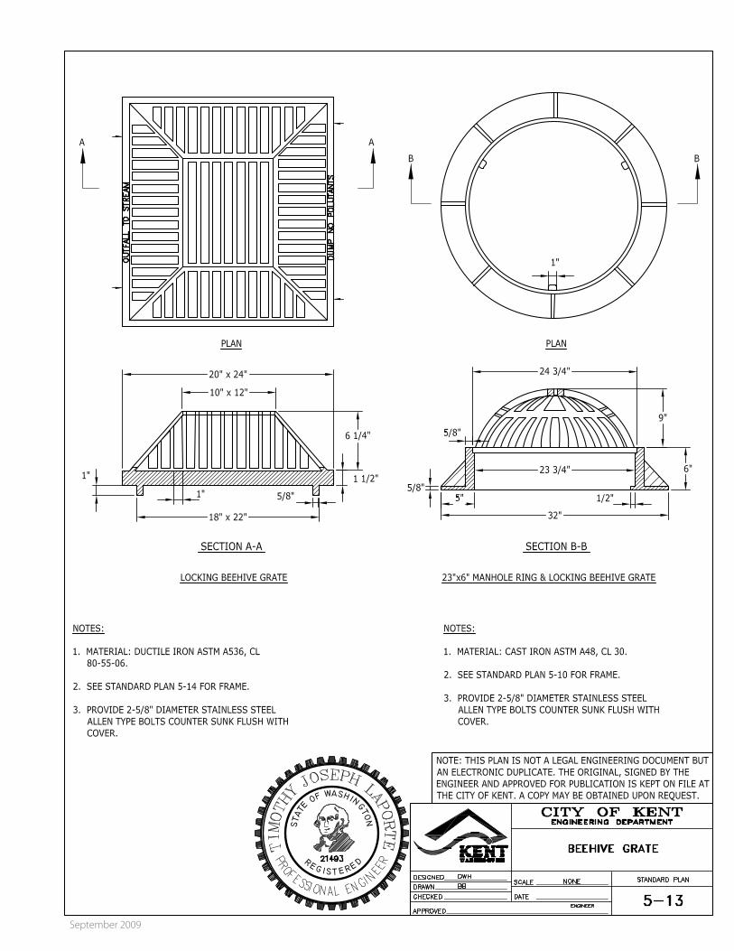
5-13 Beehive Grate
5-14 20” x 24” Catch Basin Frame
5-15 Debris Cage
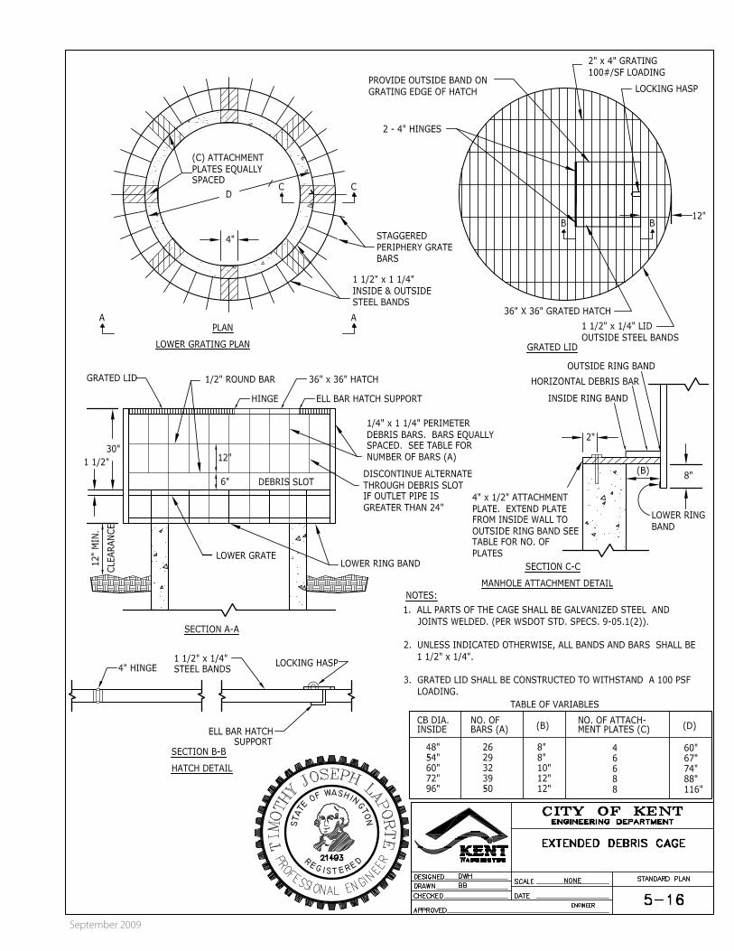
5-16 Extended Debris Cage
5-17 Catch Basin with Oil/Water Separator
5-18 Field Tapping of Concrete Pipe
5-19 Beveled End Pipe Section
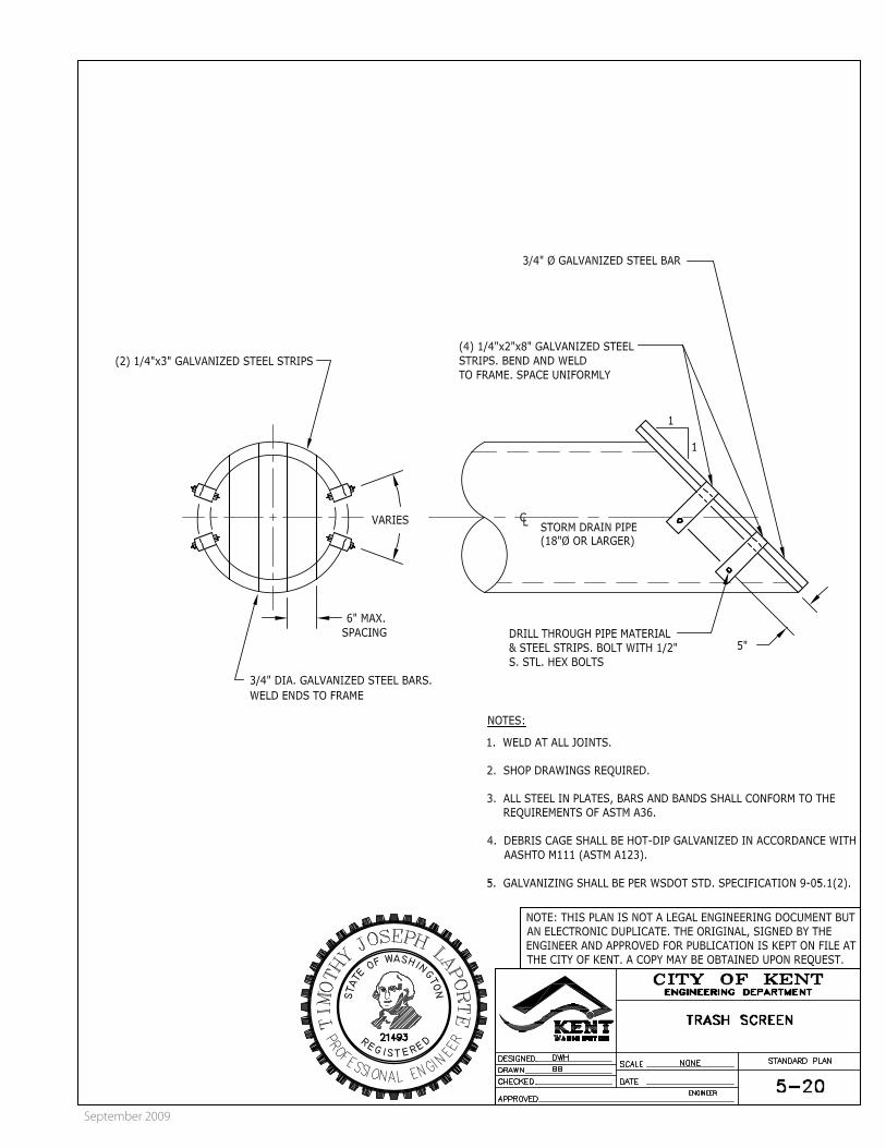
5-20 Trash Screen
5-21 Shear Gate
5-22 Chain Link Fence, Type I for Ponds Only
5-23 Driveway and Walk Gate for Ponds Only
5-24 Tree Planting
5-25 Shrub Planting
5-26 Trench Infiltration System for Small Sites
5-27 Flow Spreader Option Catch Basin with Beehive Grate
5-28 Critical Areas Sign
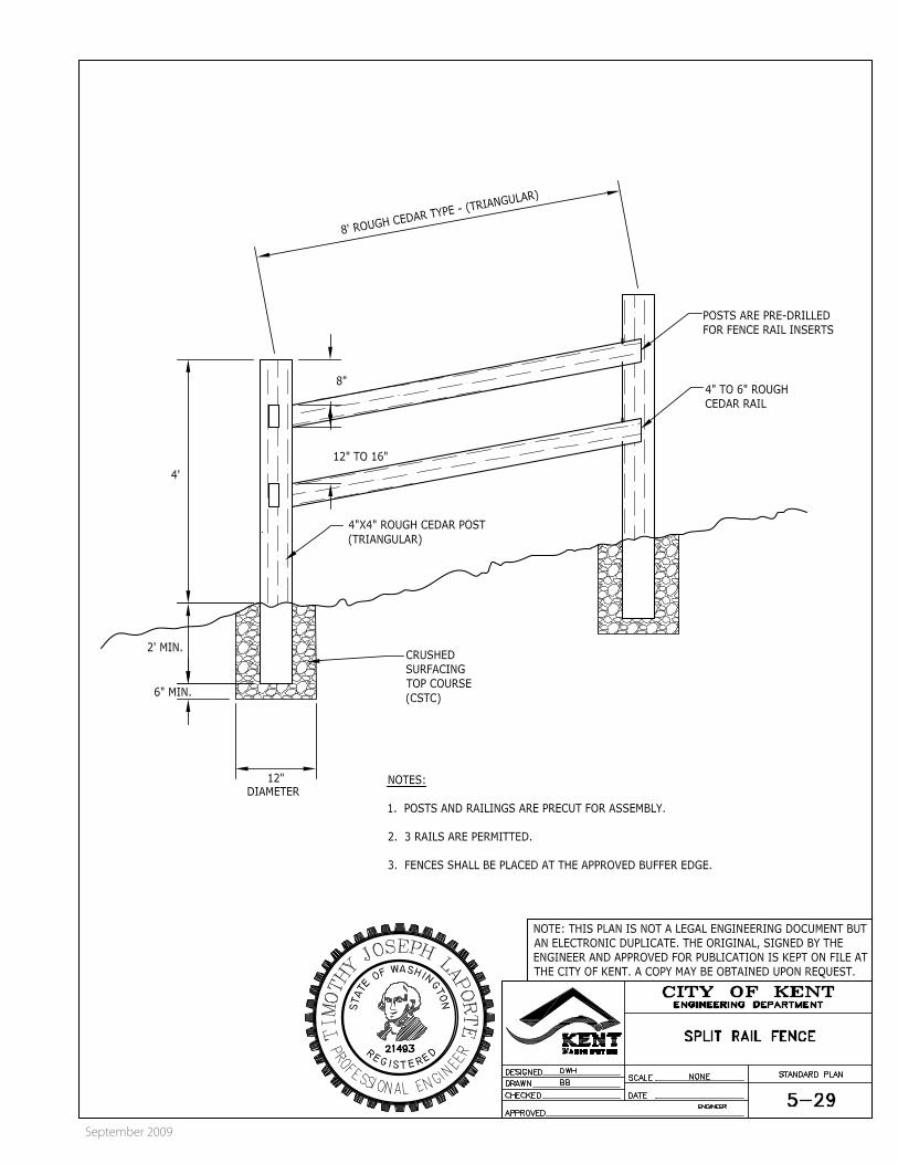
5-29 Split Rail Fence
5-30 Sample TESC Site Plan, 1 Acre and Smaller
5-31 Filter Fabric Fence
5-32 TESC Sediment Trap Earth Berm
5-33 TESC Interceptor Ditch with Rock Check Dams

2009 CITY OF KENT DESIGN & CONSTRUCTION STANDARDS
September 2009
5-8
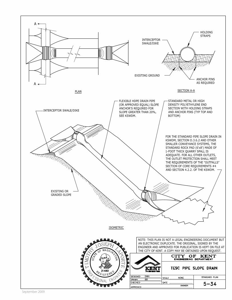
5-34 TESC Pipe Slope Drain
5-35 Temporary Stockpiling

September 2009
September 2009
September 2009

September 2009

September 2009

September 2009
September 2009

September 2009
September 2009


1 3/8"
A -------~ ~
3 1/8"
BLIND PICK NOTCH
DETAIL"A"
1 7/16"
1)16"
I Pl ·1 WASHER (SEE NOTES)
1/2" (MIN.)
1/4" DOVETAIL GROOVE WITH NEOPRENE GASKET (SEE NOTES)
BOLT -DOWN I WATERTIGHT
DETAIL "B"
l
SKID GROOVE PATTERN- SEE
DETAIL
TOP
BOTTOM
RING SECTION 0
SEE DETAIL "A"
COVER PLAN
SEE DETAIL "A"
COVER SECTION
(SEE NOTE 7)
STANDARD
TYPE1
1· 1 ..
DRILL AND TAP 5/8"- 11NC HOLE FOR 1 1/2" x 5/8" STAINLESS STEEL SOCKET HEAD CAP SCREW (TYP.)
1/2" (TYP.)
RING PLAN
27 5/8"
26 3/8"
= .....
~=+-----------+-~~~1!_· ____ 2_:_:~_ .. ____ ·~~1
TOP
SEE DETAIL "B"
34 1/8"
RING SECTION 0 SEE DETAIL "A"
COVER PLAN
SEE DETAIL "A"
COVER SECTION
(SEE NOTE 7)
BOLT-DOWN /WATERTIGHT
TYPE2
NOTES
1. The gasket and groove may be in the seat (frame) or in the underside of the cover. The gasket may be "T" shaped in section. The groove may be cast or machined.
2. Bolt-down capability is required on all frames, grates, and covers, unless specified otherwise in the Contract. Provide 3 holes in the frame that are vertically aligned with the grate or cover slots. The frame shall accept the 5/8"- 1 NC x 2" Allen head cap screw by being tapped, or other approved mechanism. Location of bolt down holes varies by manufacturer.
3. For bolt-down manhole ring and covers that are not designated "Watertight," the neoprene gasket, groove, and washer are not required.
4. Washer shall be neoprene (Detaii"B").
5. In lieu of blind pick notch for manhole covers, a single 1" pick hole is acceptable. Hole location and number of holes may vary by manufacturer.
6. Alternative reinforcing designs are acceptable in lieu of the rib design.
7. For clarity, the vertical scale of the Cover Section has been exaggerated, it is 1.5 times the horizontal scale (1H:1.5V).
SPECIFY LETTERING
ISOMETRIC VIEW
SKID GROOVE PATTERN DETAIL
CIRCULAR FRAME (RING} AND COVER
STANDARD PLAN B-30.70-03 SHEET 1 OF 1 SHEET
APPROVED FOR PUBLICATION
Pasco Bakotich Ill 04126112 STATE DESIGN ENGINEER DATE ....
~· Washington State Department of Transportation

September 2009

September 2009
September 2009

September 2009

September 2009
September 2009

September 2009
September 2009

September 2009
September 2009

September 2009

September 2009

September 2009

September 2009

September 2009
September 2009

September 2009

September 2009
September 2009

September 2009
September 2009

September 2009

September 2009
September 2009

September 2009