section 5 - ice & rain protection - aircraft services ...asd-sda.ca/pdf/c90a_ptm/5c90aptm...
TRANSCRIPT

C90A Pilot Training Manual | April 2010 i
Section 5 - Ice & Rain Protection
Ice & Rain Protection 5.1
Ice Detection 5.2
Ice Protection 5.2
Control 5.2
Operation 5.3
Engine Inlet 5.3
Pitot 5.4
Operation 5.4
Stall Warning Vane 5.4
Operation 5.4
Windshield 5.5
Windshield Anti-Ice Diagram - High Heat 5.5
Propeller Electric De-ice System 5.6
Windshield Wipers 5.6
Engine Anti-ice System 5.7
Fuel System Anti-ice 5.8

ii C90A Pilot Training Manual | April 2010
T r anspor t Canada
T r anspor ts Canada
TransportCanada
TransportsCanada

Ice & Rain Protection
Aircraft surfaces are protected from ice and rain by four different means:
• Engine exhaust air prevents ice formation on the engine air inlets.
• Electric heating elements protect the windshield panels, the propellers, both pitot masts, the stall warning vane and the pneumatic lines to the engine fuel control and propeller constant speed units.
• Airflow is diverted mechanically at the engine inlet to separate suspended particles prior to entering the compressor.
Ice
& R
ain
Prot
ecti
on
E F
C90A Pilot Training Manual | April 2010 5.1

5.2 C90A Pilot Training Manual | April 2010
Ice
& R
ain
Prot
ecti
on
E F
T r anspor t Canada
T r anspor ts Canada
TransportCanada
TransportsCanada
Ice Protection
Wing and tail deicing system.
The leading edges of the wings, and the horizontal vertical stabs are equipped with inflatable rubber boots for protection against the formation of ice. The system uses pneumatic pressure and vacuum obtained from bleed air from the engine compressors.
Pressure air is used to inflate the boots, breaking away any ice that has formed on its surface, and vacuum air is used to deflate the boots holding them tightly in place.
Control The inflation and deflation phases of operation are controlled by means of distributor valves.
• Pneumatic air is used to inflate rubber de-icing boots on the wings and empennage.
Ice Detection
During day flight, ice can be noted visually by observing ice formation on the windshield or the leading edge of the wing.
During night flight, wing inspection lights are used to illuminate the leading edges of both wings. The ICE light switch located on the pilots subpanel controls the lights.
If ice is allowed to build up on the wings, the shape of the airfoil is changed significantly, causing control problems, lack of performance and higher stall speeds.
The Ice Protection Panel and Light Switches are located on the pilot’s subpanel.

Ice
& R
ain
Prot
ecti
on
C90A Pilot Training Manual | April 2010 5.3
E F
The system is actuated by a three-way toggle switch on the inboard LH subpanel. This switch is spring loaded to return to the OFF position from either the MANUAL or the SINGLE position. Refer to Illustration on Page 5.2.
Selecting the single position causes the wings to inflate for a total of six seconds, followed by the empennage inflating for four seconds. A bump in the pneumatic pressure gauge between the wing and empennage inflation will help to confirm the proper operation of the boots.
Selecting the manual position causes the wings and empennage to inflate and stay inflated as long as the switch is held in position. Releasing the switch causes the distributor valve to return to off, deflating the boots.
OperationWhen approximately 1/2 to 1 inch of ice accumulates on the wing, the switch is selected to SINGLE cycle. This causes the boots to inflate as detailed above. If the SINGLE cycle fails, the switch may be held in the manual position for a maximum of 7 seconds to remove the ice. Holding the switch for more than seven seconds is not recommended, as ice may start to form on the expanded boot, which may be impossible to remove.
Each engine supplies a common pneumatic manifold. The system is capable of being operated on just one engine. A check valve is incorporated into the bleed air line
from each engine to prevent the escape of air into the failed engine compressor.
Engine Inlet
The lip around each engine air inlet is heated by hot engine exhaust to counteract ice accumulation on the engine inlet. A scoop in the left exhaust stack on each engine diverts a portion of the hot exhaust downward through a duct into the hollow lip of each engine inlet. The exhaust is then ducted back to the right exhaust stack of each engine where it is expelled into the atmosphere.
WarningThe engine air inlet anti ice is heated by engine exhaust any time the engine is running. After engine shutdown, allow sufficient time for the inlet lip to cool before touching.
Engine Inlet

5.4 C90A Pilot Training Manual | April 2010
Ice
& R
ain
Prot
ecti
on
E F
T r anspor t Canada
T r anspor ts Canada
TransportCanada
TransportsCanada
PitotA heating element in the pitot mast prevents the pitot opening from becoming clogged with ice. The heating element is connected to the airplane electrical system through circuit breaker switches placarded PITOT LEFT and RIGHT, located on the left inboard subpanel. See illustration on page 5.2.
OperationBoth pitot heat switches are turned on prior to take-off and left on for the duration of the flight. The system should not be left on for extended periods on the ground, as this could cause damage to the elements due to over-heating.
Pitot Tubes
Stall Warning Vane
The stall-warning vane has heat applied to both the mounting plate and the vane. There is no over-heat protection except for the circuit breaker switch.
OperationA switch located in the ICE PROTECTION GROUP on the pilot’s subpanel placarded STALL WARN – OFF controls the heat. The level of heat is minimal for ground operation, but is automatically increased for flight operation through the left landing gear safety switch. See illustration on page 5.2. and 5.4

Ice
& R
ain
Prot
ecti
on
C90A Pilot Training Manual | April 2010 5.5
E F
Windshield
Each windshield is protected against icing by a heating element and electrical connections, which is incorporated in the lamination. The windshield is made up of three individual layers. The inside layer is thick glass, acting as a structural member. The outside layer is not structural, but consists of a thinner layer of glass. Bonded between the outer and inner layer is a polyvinyl sheet containing the heating elements. This resistive material is arranged so as to provide a primary heating surface of 266 sq inches and a secondary heated surface of 95 square inches for a total of 361 square inches. Selecting the WSHLD ANTI-ICE switch to NORMAL on the pilot or copilots side heats the larger area to maintain a temperature
between 90˚ and 110˚F. Selecting either side to HIGH maintains this temperature in the primary heating surface area of the windshield which is in the prime viewing area. Sensors imbedded in the windshield control temperatures.
Power to each windshield is controlled through 50 amp current limiters and 5 amp windshield heat control circuit breakers.
Switches located in the ICE PROTECTION group are marked: WSHLD ANTI-ICE: NORMAL/OFF/HIGH, PILOT and COPILOT. See illustration on page 5.2.
CautionErratic operation of the magnetic compass will occur while the windshield heat is being used.
Windshield Anti-Ice Diagram - High Heat

5.6 C90A Pilot Training Manual | April 2010
Ice
& R
ain
Prot
ecti
on
E F
T r anspor t Canada
T r anspor ts Canada
TransportCanada
TransportsCanada
Propeller Electric De-ice System
The propeller de-ice system consists of electric heating elements in rubber boots fitted to each propeller blade. Electrical power is applied to the boots through brushes and slip rings through an ON/OFF switch and a timer.
When the prop de-ice is turned on, (5 amps per blade) is applied to the propeller boots. The current flows from a timer to the blades through the brush assemblies and slip rings.
The system is referred to as de-ice as opposed to anti-ice because of its operation. Power to the deicer boots is cycled in 90 second phases. The first phase applies current to the boots of the right hand propeller, followed by 90 seconds to the left hand propeller. This allows for a complete cycle every 3 minutes. As the rubber boots heat up, any ice adhering to the propeller is loosened, and the inertia of the prop removes it. Thus, because the system is designed to remove rather than inhibit the formation of ice it is called a de-icing system.
A prop heater ammeter is located on the overhead electrical panel. Normal operation would indicate 14-18 amps, with a very slight needle movement as the prop heater cycles. Because the system may cause the boot to overheat without the prop moving, it must not be used with the engine not running.
Windshield Wipers
Dual windshield wipers are driven by a single 28 volt DC electric motor. The system also includes a single control switch located on the overhead control panel (upper left corner) and a circuit breaker located on the right sidewall circuit breaker panel. Power for the system is from the center bus. Windshield wipers may be used during either ground or flight operations, with no airspeed limitations.
The switch control is placarded: WINDSHIELD WIPER PARK/OFF/SLOW/FAST, and a note, DO NOT OPERATE ON DRY GLASS
Prop Amp Meter located on Overhead Control Panel Pg 5.7
Windshield Wiper Control

Ice
& R
ain
Prot
ecti
on
C90A Pilot Training Manual | April 2010 5.7
E F
Engine Anti-ice System
An electrically actuated inertial vane system on each engine prevents ice or other foreign objects such as dust or sand from entering the engine inlet plenum and prevents ice from accumulating on the engine inlet screen.
Selecting ENGINE ANTI-ICE ON lowers vanes located in the engine inlet slightly, creating a venturi effect, and introduces a turn of the air entering the engine. A bypass door located at the end of the air duct opens with the vane. As ice particles or water droplets enter the air inlet, they accelerate due to the venturi effect of the extended vane. Due to their mass and momentum, the moisture and ice particles accelerate past the screen
and discharge overboard through the bypass door as the air stream makes the sudden turn before entering the engines through the inlet screen.
Switches located on the left subpanel, in a group called ENGINE ANTI-ICE, control the engine anti-ice vanes, and bypass door. The switches are placarded: LEFT/RIGHT and ON/OFF, ACTUATORS STANDBY/MAIN.

5.8 C90A Pilot Training Manual | April 2010
Ice
& R
ain
Prot
ecti
on
E F
T r anspor t Canada
T r anspor ts Canada
TransportCanada
TransportsCanada
When the ice vanes are extended, two green advisory annunciators marked L or R ENG ANTI-ICE illuminate. It is considered good airmanship to verify that a drop in torque and a slight increase in ITT has occurred. This is due to the airflow restriction effect of the vanes. When the ice vanes and bypass doors retract, the annunciators extinguish, torque is restored, and ITT decreases.
Located below the engine anti-ice switches in the ENGINE ANTI-ICE group are two switches marked ACTUATORS, and STANDBY/MAIN. Refer to illustration on page 5.7. This redundant feature allows the selection of either the main or standby actuator motor in case of failure of the selected motor. Power for this system is as follows: The left generator bus provides power for the left anti-ice and right standby Anti-ice (ice vane). The right generator bus will provide power to the right anti-ice and left standby anti-ice.
Illumination of the L or R ENG ANTI-ICE FAIL indicates that the system did not operate to the desired position. Immediate illumination of the L or R ENG ICE FAIL annunciator indicates a loss of electric power, whereas delayed illumination (35 seconds) indicates an inoperative actuator, ie the selector switch and the position of the vanes do not agree.
Fuel System Anti-ice
Two anti-ice systems protect fuel flow through the fuel lines to the engines; one system protects the fuel and the second protects the fuel vents.
From the aircraft nacelle fuel tank, fuel flows through an oil-to-fuel heat exchanger where hot engine oil heats the cold fuel. The heat exchanger consists of a two-pass oil circuit and a two-pass fuel circuit. Heat transfer between the oil and fuel occurs through conduction, and melts any ice particles in the fuel. This operation is automatic whenever the engine is running.
Oil to Fuel Heat Exchanger
Ice
& R
ain
Prot
ecti
on
C90A Pilot Training Manual | April 2010 5.9
E F
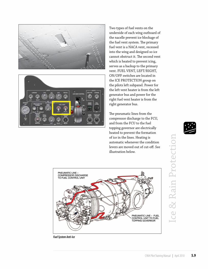
Two types of fuel vents on the underside of each wing outboard of the nacelle prevent ice blockage of the fuel vent system. The primary fuel vent is a NACA vent, recessed into the wing and designed so ice cannot obstruct it. The second vent which is heated to prevent icing, serves as a backup to the primary vent. FUEL VENT, LEFT/RIGHT, ON/OFF switches are located in the ICE PROTECTION group on the pilots left subpanel. Power for the left vent heater is from the left generator bus and power for the right fuel vent heater is from the right generator bus.
The pneumatic lines from the compressor discharge to the FCU, and from the FCU to the fuel topping governor are electrically heated to prevent the formation of ice in the lines. Heating is automatic whenever the condition levers are moved out of cut-off. See illustration below.
Fuel System Anti-Ice

5.10 C90A Pilot Training Manual | April 2010
Ice
& R
ain
Prot
ecti
on
E F
T r anspor t Canada
T r anspor ts Canada
TransportCanada
TransportsCanada
OPERATIONAL USE OF PNEUMATIC DE-ICING BOOTS
Pilots of aeroplanes fitted with pneumatic de-icing boots will find direction on operational use of the boots in the AFM. In most cases the AFM will direct pilots to delay operation of the pneumatic de-icing boots, either in the manual mode or automatic mode (if fitted), until 1 inch of ice has built up on the leading edge. As pointed out above, this guidance is almost universally included to prevent the occurrence of ice bridging. In its report on the fatal accident of a Comair EMB-120 in January 1997, the NTSB has concluded that a small amount of rough ice had built up on the wing as the aircraft slowed to configure for an approach, but this small amount was sufficient to cause the aircraft to stall without warning as speed decreased. As a result, the NTSB recommends that, for modern turboprop aeroplanes:
“…leading edge deicing boots should be activated as soon as the aeroplane enters icing conditions because ice bridging is not a concern in such aeroplanes and thin amounts of rough ice can be extremely hazardous.”
Unless specifically prohibited by the AFM, it is recommended that pilots of turboprop aeroplanes equipped with pneumatic de-icing boots with an automatic cycle select the boots on automatic as soon as the aeroplane enters icing conditions. The pneumatic de-icing boots should be left on until the
aeroplane has departed the icing conditions. If the automatic cycle has a FAST/SLOW option, the FAST option should be selected in moderate or severe icing conditions.