section 40.06 asphalt concrete pavement...with aashto t-308. the aggregate gradation of the job-mix...
TRANSCRIPT
SECTION 40.06 ASPHALT CONCRETE PAVEMENT
Delete the Section and add the following in its place:
Article 6.1 Description The Work under this Section consists of the performance of all Work required for the construction of asphalt concrete pavement on a prepared base.
Article 6.2 Material and Testing
A. Asphalt: Shall conform to the State of Alaska Department of Transportation Type II Class A.
B. Aggregates
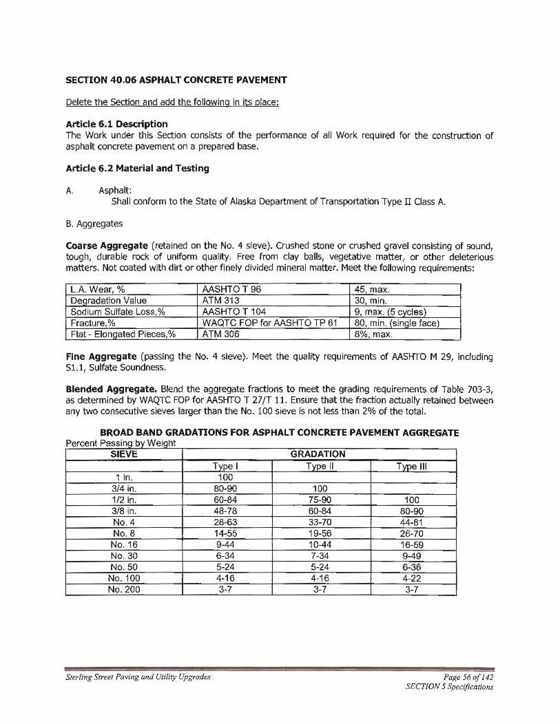
Coarse Aggregate (retained on the No. 4 sieve) . Crushed stone or crushed gravel consisting of sound, tough, durable rock of uniform quality. Free from clay balls, vegetative matter, or other deleterious matters. Not coated with dirt or other finely divided mineral matter. Meet the following requirements :
L.A. Wear, % AASHTO T 96 45, max. Degradation Value ATM 313 30, min. Sodium Sulfate Loss,% AASHTO T 104 9, max. (5 cycles) Fracture,% WAQTC FOP for AASHTO TP 61 80, min. (single face) Flat - ElonQated Pieces,% ATM 306 8%, max.
Fine Aggregate (passing the No. 4 sieve). Meet the quality requirements of AASHTO M 29, including Sl.1, Sulfate Soundness.
Blended Aggregate. Blend the aggregate fractions to meet the grading requirements of Table 703-3, as determined by WAQTC FOP for AASHTO T 27/T 11. Ensure that the fraction actually retained between any two consecutive sieves larger than the No. 100 sieve is not less than 2% of the total.
BROAD BAND GRADATIONS FOR ASPHALT CONCRETE PAVEMENT AGGREGATE p p b w . h ercent assmQ 1y e1Q t
SIEVE Type I
1 in. 100 3/4 in. 80-90 1/2 in. 60-84 3/8 in. 48-78 No. 4 28-63 No. 8 14-55
No. 16 9-44 No. 30 6-34 No. 50 5-24 No.100 4-16 No. 200 3-7
Sterling Street Paving and Utility Upgrades
GRADATION Type II
100 75-90 60-84 33-70 19-56 10-44 7-34 5-24 4-16 3-7
Type Ill
100 80-90 44-81 26-70 16-59 9-49 6-36 4-22 3-7
Page 56of142 SECTION 5 Specifications

Article 6.3 Composition of Mixes
A. General Requirements Paving mixtures prepared under these Specifications shall be composed of aggregate and paving asphalt within the limits set forth in the following table :
Asphalt paving mixtures prepared under these Specifications shall be composed of aggregate and asphalt cement within the limits set forth in the following table:
ASPHALT CONCRETE MIX DESIGN REQUIREMENTS
CLASS CLASS CLASS DESIGN PARAMETERS "A" "B" "C" Stability, pounds 1800 min. 1200 min. 750 min.
Flow, 0.01 inch 8-14 8-16 8-18
Voids in Total Mix, % 3-5 3-5 2-5
Compaction, number of blows each side of test specimen 75 50 35
Percent Voids Filled with Asphalt (VFA) 65-75 65-78 70-80 Dust-asphalt ratio* 0.6-1.4 0.6-1.4 N/A
Voids in the Mineral Aggregate (VMA), %, min. Type I 12.0 11.0 N/A Type II 13.0 12.0 N/A Tvoe Ill 14.0 13.0 N/A
*Dust-asphalt ratio is the percent of material passing the No. 200 sieve divided by the percent of effective asphalt (calculated by weight of mix).
The approved Job Mix Design will specify the target values for gradation, the target value for asphalt cement content, the Maximum Specific Gravity (MSG) of the mix, the additives, and the allowable mixing temperature range.
Target values for gradation in the Job Mix Design must be within the broad band limits shown in Table 703-3, for the type and class of asphalt concrete specified.
Do not produce asphalt concrete mixture for payment until the Engineer approves the Job Mix Design. Do not mix asphalt concrete mixtures produced from different plants.
B. Additive Materials A "non-stripping" additive shall be added to the asphalt in the amount determined by ATM T-14 or one-fourth percent (0.25%) by weight of the asphalt, if approved by the Engineer. Such additive material shall be of quality and grade acceptable to the Engineer.
C. Job Mix The Contractor, at his expense, shall submit to the Engineer for approval, a job mix formula within the limits specified above, for each class of mix designated by the Contract. Within each mix design the Contractor shall provide correction factor ignition points generated in accordance
Sterling Street Paving and Utility Upgrades Page 57 of 142 SECTION 5 Specifications

with AASHTO T-308. The aggregate gradation of the job-mix formula, when plotted upon an aggregate grading chart, shall closely approximate the shape of average gradations for the limits specified. For that portion of the aggregate passing No. 4 sieve, gradings which range from at or near the maximum of one (1) sieve to at or near the minimum of the next sieve will not be permitted. The Engineer may require increased asphalt content up to one-half percent (0.5%) above that indicated by Marshall Design Criteria. Upon requiring increased asphalt content, the lower limit of percent voids and the upper limit of percent voids filled shall be waived.
D. Maximum Permissible Variations Tolerances to the approved Job Mix Formula shall not exceed the permissible variations presented in the following table. The Job Mix Formula band shall mean the approved Job Mix Formula plus-or-minus(±) the numeric values for the maximum permissible variations.
Sieve Size 3/8" and Larger #4 #8 #s 16, 30 & 50 #100 #200 Asphalt
Maximum Permissible Variation (Percent by Weight of Total Aggregate)
Class A Asphalt ± 6.0 ± 5.0 ± 5.0 ± 4.0 ± 3.0 ± 2.0 ± 0.4
Class D & E Asphalt ± 5.0 ± 5.0 ± 4.0 ± 4.0 ± 3.0 ± 2.0 ± 0.4
When these permissible variations are applied to the "Class A Asphalt Concrete" Job Mix formula, the broad band limits in Subsection A, above, may be exceeded only as follows:
1. The three-quarter inch (3/4'') and No. 200 sieves shall not exceed the broad band limits in SubArticle 6.3.A - General Requirements;
2. All other sieves may exceed the broad band limits in SubArticle 6.3.A - General Requirements for the respective sieve sizes in the above table provided that the Job Mix Formula band is not exceeded.
When these permissible variations are applied to the "Class D or Class E Asphalt Concrete" Job Mix formulas, the individual sieve shall not exceed the Broad Band limits in SubArticle 6.3.A - General Requirements, above. Maximum temperature shall not vary more than twenty-five degrees (250) Fahrenheit from the approved Job Mix Formula design.
Article 6.4 Equipment
A. General
All equipment furnished by the Contractor shall be maintained in a sound mechanical condition. Equipment shall be serviced and lubricated away from the paving site; units that drip fuel, oil and/or grease shall be removed from the Project until such leakage is corrected to the satisfaction of the Engineer.
Sterling Street Paving and Utility Upgrades Page 58of142 SECTION 5 Specifications

B. Asphalt Mixing Plant
All plants, used by the Contractor, shall be designed, coordinated and operated to produce a mix uniformly within the job- mix tolerances as listed herein and in accordance with AASHTO M-156. The plant may be either a weightbatch type or a volumetric proportioning, continuous/drum mixing type, provided the equipment has demonstrated that it is suitable for producing finished mixtures complying with the job-mix formula specified herein.
The plant shall be equipped with the necessary equipment for storing, handling, drying, heating and mixing the aggregate and asphalt. Satisfactory means shall be provided for aggregate and asphalt control as to quantity and temperature. Adequate safety measures shall be provided on stairs, gears, pulley, chains, sprockets, and all other dangerous moving parts.
Contractor shall calibrate the asphalt plant not more than thirty (30) days in advance of production and furnish copies of the data to the Engineer at least one day prior to asphalt concrete production. Aggregate and asphalt cement sampling locations meetings OSHA safety requirements shall be provided. Proportioning (batch) scales shall not be used for weighing material for payment. Weight scales used in conjunction with a storage silo may be used to weight the final product for payment, provided the scales are certified by the State of Alaska. The asphalt plant shall maintain a current Air Quality Permit issued by the State of Alaska.
C. Pavers
Asphalt pavers shall be self-propelled units provided with a heated vibratory screed. Grade and cross slope shall be controlled through the use of automatic grade and slope control devices. The paver screed control system shall be automatically actuated by the use of an erected string-line or a mobile string-line (ski) at least thirty feet (30') in length on the high side of the paver. Grade control shall be used on either (a) both the high and low sides, or (b) grade control on the high side and slope control on the low side.
The Contractor may request a waiver for the screed control system (string-line or ski) if he or she believes the paving grade poses an unreasonable obstacle in the form of extreme horizontal or vertical curves or unusual cul-de-sac and/or street configuration.
For trails, pavers shall be capable of placing the required thickness in one lift with a minimum paving width of five feet (5'), truck-towed spreader-type equipment will be permitted, providing the width and depth requirement can be met.
The paver shall be equipped with a receiving hopper having sufficient capacity for a uniform spreading operation. The hopper shall be equipped with a distribution system to place the asphalt concrete mixture uniformly in front of the screed without segregation and/or tearing.
The term "screed" includes any strike-off device operated by cutting, crowding, or other action which is effective on mixes at workable temperatures, without tearing, shoving, or gouging, and which produces a finished surface of an even and uniform texture. The screed shall be adjustable as to level and section and shall have provisions for vibration and heat.
The screed assembly shall produce a finished surface of the required smoothness, thickness, and texture without tearing, shoving, displacing or segregating the asphalt concrete mixture. Screed extensions used for paving a constant width shall be heated and vibrated. Auger extensions shall be within one and one-half feet (1.5') of the screed extension on both sides.
Sterling Street Paving and Utility Upgrades Page 59of 142 SECTION 5 Specifications

The paver shall be capable of placing courses in thicknesses of from one-half inch (1/2") to at least three inches (3"), and, in width, be adjustable in increments of six inches (6'') and one foot (1 ').
The use of a pick-up machine to transfer the asphalt concrete mixture from a windrow to the paver hopper will be permitted, provided the pick-up machine is capable of collection of the windrowed material without damage to the underlying course. The Engineer will not allow the continued use of the pick-up machine if segregation, excessive temperature loss, or any detrimental effects are observed.
Paver shall be equipped with a means of preventing the segregation of the coarse aggregate particles from the remainder of the bituminous concrete mixture while being carried from the paver hopper over the slat-conveyor to the auger chamber. The mechanism to accomplish this must be approved in writing by the paver manufacturer and may consist of chain curtains, deflector plates, or other devices and may be any combination of these.
The following specific requirements apply to the following identified bituminous pavers:
1. Blaw-Knox bituminous paver shall be equipped with the Blaw-Knox Materials Management Kit (MMK). 2. Cedarapids bituminous paver must have been manufactured in 1989 or later. 3. caterpillar bituminous pavers shall be equipped with the following deflector plate models: 6630, 6631, or 6640.
Contractor shall provide a Certificate of Compliance that verifies the required mechanism has been installed to prevent bituminous paver segregation.
The Engineer shall approve all mechanisms proposed by Contractor for preventing paver segregation of coarse aggregate prior to the bituminous paver's use on the project.
D. Rollers
Rollers shall be self-propelled, reversible, and equipped to maintain clean and straight contact surfaces. Heat shall be maintained on pneumatic tires by skirting or other approved devices.
The number, weight, and type of rollers furnished shall be sufficient to obtain the required density and surface requirements while the mix is in a workable condition. One pneumatic and a minimum of one vibratory roller shall be furnished and operated in a workmanlike manner by the Contractor. There shall be at least one operator for each roller.
Pneumatic Tired Rollers:
Pneumatic tired roller shall ride on not less than seven uniformly sized and uniformly inflated smooth tires mounted on wheel rims of twenty inch (20'') minimum diameter. The rear group of tires shall align behind and cover the spaces between the forward group of tires. Tires shall be inflated, and the roller ballasted, to provide a uniform (plus or minus five [SJ pounds per square inch) minimum ground contact weight of seventy (70) pounds per square inch, unless a lower weight is requested in writing by the Engineer. If a pneumatic roller experiences a pick-up problem, the Contractor shall be required to add an effect release agent to the tire watering tank.
Sterling Street Paving and Utility Upgrades Page 60 of I 42 SECTION 5 Specifications

Steel-Drum Rollers: Steel-wheel roller may be of two (2) types:
Two-axle static drum rollers, 8 to 22 tons in weight.
Two-axle vibratory drum rollers, 8 to 22 tons in weight.
All rollers shall be equipped with power units of not less than four ( 4) cylinders and under working conditions shall develop a compression in the rear wheels of two hundred fifty (250) to three hundred fifty (350) pounds per inch of roller width. Rollers shall be in good working condition and be free from backlash, faulty steering mechanism, or worn parts. Rollers shall be equipped with adjustable scrapers to keep the drums clean and with efficient means of keeping the drums/wheels wet to prevent mixes from sticking to the drums. Rollers/Drums shall be free of flat areas, openings or projections which will mar the surface of the pavement.
E. Haul Trucks
Vehicles used for the transportation of hot-mix asphalt from the plant to the Project shall have tight metal bottoms and shall be free from dust, screenings, petroleum oils, volatiles, and other mineral spirits which may affect the mix being hauled. The truck beds shall be cleaned as often as required, but at least once a day. After this operation the truck bed shall be elevated and thoroughly drained; no excess solution shall be permitted.
When requested by the Engineer, trucks shall be equipped with covers of canvas, insulated boxes, or other suitable material, and be of sufficient size and weight to protect the load from adverse weather conditions and to maintain the required mix temperatures.
F. Truck Scales
Hot mix asphalt shall be weighed on platform scales furnished by the Contractor or on public scales at the Contractor's expense. The scales shall be satisfactory to the Engineer and shall comply with all State Laws governing the use of scales. The scales shall be tested and sealed by an authorized public official, at the expense of the Contractor, as often as the Engineer may deem necessary to ensure their accuracy. Batch plant proportioning scales may be used in lieu of truck scales only with the written approval of the Engineer.
G. Hand Tools
Only lutes or asphalt rakes shall be used during the spreading operation and when finishing by hand.
Tamping irons shall weigh not less than twenty-five (25) pounds and shall have a bearing area not exceeding forty-eight ( 48) square inches. Mechanical compaction equipment, satisfactory to the Engineer, may be used instead of tamping irons.
H. Straightedges
Straightedges ten (10') and sixteen feet (16') in length, to test the finished surface, shall be provided by the Contractor. The sixteen foot (16') straightedge shall be used on straight sections and the ten foot (10') straightedge on vertical curves or crown.
Sterling Street Paving and Utility Upgrades Page 61 of 142 SECTION 5 Specifications

Article 6.5 Construction
A. Weather Limitations
Asphalt concrete mixture shall not be placed when it is raining or when rain is imminent, on a saturated surface, on an unstable/yielding roadbed, when the base material is frozen, or when weather conditions prevent proper handling or finishing of the mixture. Asphalt concrete mixture shall not be placed unless the surface temperature is forty-five degrees ( 450) Fahrenheit or warmer and the ambient air is at least thirty-two degrees (32°) Fahrenheit and not descending. Air temperature shall be measured in the shade away from heat sources at the paving site.
B. Preparation of Area to be Paved
The area to be paved shall be true to line and grade, having a smooth dry, compacted surface prior to the start of paving operations. The area to be paved shall be free from all loose asphalt and foreign material.
Contractor shall notify the Engineer, a minimum of twenty-four (24) hours prior to paving, that the newly constructed, rotomill planed, or existing surface, has been prepared in conformance with the Drawings and Specifications and are ready to be paved. Engineer or his representative shall inspect the grade through the use of string line, straightedge, levels, or any other means necessary. Upon determining the grade that has been proposed for paving is in conformance with the Drawings and Specifications, Engineer will provide written authorization for the Contractor to proceed with the paving. The Contractor shall not initiate paving prior to receiving written authorization to proceed.
The surface of the Leveling Course, when finished, shall not demonstrate any deviation in excess of three-eighths inch in ten feet (3/8" in 10') parallel with, and at right angles to, the centerline, or more than five-eighths inch (5/8") total from centerline to face of curb of the area to be paved. Any deviation in excess of this amount shall be corrected by loosening, adding, or removing material and reshaping and compacting to satisfy the above requirement.
Existing paved surfaces shall be cleaned of loose material by sweeping with a power broom, supplemented by hand sweeping, if determined necessary by the Engineer.
After rotomilling of a section of the roadway has been completed, that section shall be inspected by the Engineer for areas of distress or failure. Areas requiring repair shall have the remaining pavement removed, and the distressed area shall be excavated to the depth and limits directed by the Engineer. The excavated area shall be backfilled, as directed by the Engineer, with crushed aggregate Leveling Course material and/or Asphalt Concrete leveling course in conformance with the Drawings and Specifications. Pavement surface irregularities, remaining from the rotomilling effort, that extend more than three-quarters inch (3/ 4'') below the milling indentations shall be pre-leveled and brought into conformance with the tolerances established in Article 6.6 - Density and Surface Requirements. Pre-leveling shall be completed with an approved Class D asphalt concrete in accordance with this Section and include the furnishing, hauling, placing, and compaction of the asphalt concrete.
Contact surfaces of curbing, gutters, manholes, and other structures shall be painted with a thin, uniform coating of asphaltic cement or approved equal material prior to the mixture being placed against them. Butt joints on previously placed cooled pavement shall be saw cut and tack coated prior to continuing the paving operation.
Sterling Street Paving and Utility Upgrades Page 62 of I 42 SECTION 5 Specifications

Contractor shall not pave against newly placed concrete curbing until said curbing has cured for a minimum five (5) days. For the purpose of paving operations only, curb curing time may be reduced to seventy-two (72) hours only upon receipt of Contractor's written certification that Type III Portland High-Early-Strength cement concrete was used in, properly placed, and appropriate curing compounds were applied to the adjacent curb and gutter.
C. Preparation of Paving Asphalt
The asphalt shall be heated at the paving plant to a temperature at which it can be properly handled through the pumping system, but at no t ime shall the temperature of the asphalts exceed that recommended by the asphalt supplier or manufacturer, or be greater than three hundred twenty-five degrees (325°) Fahrenheit or less than two hundred fifty degrees (2500) Fahrenheit.
D. Preparation and Handling of Aggregates
The aggregate for the asphalt concrete mixture shall be heated and dried to a temperature compatible with the mix requirements specified. The burner on the dryer shall be properly adjusted to avoid damage to the aggregate and to avoid the presence of unburned fuel on the aggregate. Any asphalt concrete mixture in which soot or fuel is present shall be wasted and no payment made.
Drying operations shall reduce the aggregate moisture content so that the moisture content of the asphalt concrete mixture, sampled at the point of acceptance for asphalt cement content, shall be no more than one-half percent (0.5%) (by total weight of mix), as determined by ATM T-25. Adequate dry storage shall be provided for the mineral filler.
Aggregates shall be stored at the plant in such a manner that the separate sizes will not become intermixed. Cold aggregate shall be carefully fed to the plant in such proportions that surplus and shortages in the hot bins will not cause breaks in the continuous operations.
Stockpiles and bins shall be sampled for gradation analysis, dust coating, and for other purposes, at the option of the Engineer.
When requested by the Engineer, the Contractor shall provide representative samples from each of the hot bins. Samples shall be used to determine compliance with these Specifications.
1. Drying: The aggregate shall be thoroughly dried and heated to provide a paving mix within a tolerance specified herein. The moisture content of the heated and dried aggregate shall not exceed one-half percent (0.5%). Dust collected during the drying operation may be fed uniformly back into the hot aggregate prior to screening, provided a position mechanical feed is used which will control the feedback to the quantity specified by the Engineer.
2. Screening: Aggregates shall be screened into sizes that may be recombined into a gradation meeting the requirements of the job-mix formula . Screens shall have normal capacities slightly in excess of the production capacity of the mixer and rated capacity of the dryer.
Sterling Street Paving and Utility Upgrades Page 63 of 142 SECTION 5 Specifications

3. Hot Aggregate Storage: Hot screened aggregate shall be stored in such a manner as to minimize segregation and loss of temperature.
E. Mixing Plants and Controls
All plants shall be equipped with a positive means to govern the time of mixing. Mixing time shall not be altered unless requested by the Engineer. Frequent gradation analysis of the hot aggregates of the completed mix shall be made to be certain that the materials being used and produced are within the tolerances of the job-mix formula and the specifications of the mix being used. If the mix is found to be outside the hot-mix formula tolerances or outside the specification limits, corrections shall be made in quantities measured from the hot bins and suitable changes made at the cold bin feeders. It shall be the responsibility of the Contractor to furnish a fin ished product in accordance with the Contract Documents. Tests conducted by the Engineer are for quality acceptance purposes only and are not authorized for use in plant calibration. Plant metering systems and scales shall be calibrated to the accuracy specified in AASHTO M-156.
Batch Type Plant: When the mix is produced in a batch type plant, the aggregate shall be accurately weighed in the proper proportions to provide the batch weight.
The asphalt shall be heated to provide a material sufficiently fluid to produce a uniform coating on every particle of aggregate within the specified mixing time. The temperature of the aggregates and asphalt immediately prior to mixing shall be approximately that of the completed batch. In no case shall the temperature of the asphalt and aggregate vary more than twenty-five degrees (25°) Fahrenheit when placed in the mixing chamber.
A dry mixing period of not less than ten (10) seconds shall precede the addition of the asphalt to the mix. Excess wet mixing shall be avoided. Wet mixing shall continue as long as is necessary to obtain a thoroughly blended mix. The minimum percent of coated particles used to establish the mixing time interval shall be ninety-five percent (95%) as determined by AASHTO T-195.
Continuous Type Plant: Continuous mix and drum plants shall in general be controlled in the same manner as batch plants.
The determination of mixing time shall be by weight method under the following formula unless otherwise approved:
Mixing time in seconds = Pugmill Dead capacity in Pounds Pugmill Output in Pounds Per Second
The weights used for computing mixing time shall be determined for the job, from tests made by the Contractor and shall conform to the recommendations of the manufacturer. Mixing temperature shall not exceed that recommended by the asphalt cement manufacturer without the written approval of the Engineer. To aid in determining the proper temperature of the completed batch, current viscosity data shall be available at the plant at all times.
F. Transportation of Mix
The dispatching of the hauling vehicles shall be so scheduled that all material delivered may be placed and rolled in daylight. When variations in size of loads, speed of trucks, length of haul, and conditions of trucks interfere with orderly continuous operations, the Engineer may order suitable corrections to be made.
Sterling Street Paving and Utility Upgrades Page 64 of 142 SECTION 5 Specifications

G. Mechanical Spreading
Contractor shall submit a Paving Plan for the Engineer's review a minimum of five (5) working days prior to initiating paving operations. The plan shall consist of at least the following items:
1. Paving schedule to include sequence of operations. 2. Operational details to include:
a. Plant operating capacity and target production rate. Process control testing frequency for gradation, moisture, asphalt cement content, and compaction.
b. Number and capacity of trucks, cycle time, and delivery rate. c. The manufacturer and model of the paver and pick-up machine to
include information on grade followers, sensors, operating speed, and production rate of the pavers.
d. Number, type, weight, and operating speed of rollers, including replacement roller.
e. Location and method of constructing longitudinal and transverse joints.
f. Construction plan for paving intersections and driveways.
3. The asphalt concrete shall be placed on the road surface at a temperature not less than two hundred fifty degrees (2500) Fahrenheit or greater than three hundred degrees (3000) Fahrenheit. Additionally, the maximum temperature to which the asphalt concrete is heated shall not exceed the supplier's recommendation. The asphalt concrete temperature shall be measured directly behind the paver screed at the time of placement.
The asphalt concrete mixture shall be laid upon a surface approved in writing by the Engineer, spread and struck-off and compacted to the thickness specified in the Drawings and specifications. Asphalt pavers shall be used to distribute the asphalt concrete mixture in lanes of such widths as to hold to a practical minimum the number of longitudinal joints required.
Longitudinal joints and edges shall be constructed to true line markings. Lines shall be established parallel to the center line for the paver to follow in placing individual lanes. The paver shall be operated and positioned to closely follow the established line. When backing trucks to the finisher, care shall be taken not to jar the paver.
The texture of the unrolled surface shall be checked to determine its uniformity. The adjustment of the screed, tamping, feed screws, hopper feed, etc., shall be checked frequently to assure uniform spreading of the mix. Segregation of the material shall not be permitted. If segregation occurs, the spreading operation shall be immediately suspended until the cause is determined and corrected.
Any irregularities left by the paver shall be corrected by trimming directly behind the machine by use of lutes or covered rakes. Immediately after trimming, the edges of the course shall be thoroughly compacted by tamping. Distortion of the pavement during this operation shall be avoided.
Edges against which additional pavement is to be placed shall be vertically formed to true line. A lute or covered rake shall be used immediately behind the finisher, when required to obtain a true line and vertical edge. Any irregularities in the surface of the pavement course shall be corrected directly behind the paver. Excess material forming high spots shall be removed by a
Sterling Street Paving and Utility Upgrades Page 65 of 142 SECTJON 5 Specifications

shovel or lute. Indented areas shall be filled with hot-mix and smoothed with the back of a shovel pulled over the surface. Fanning of material over such areas shall not be permitted.
On longitudinal joints, the paver shall be positioned so that in spreading, the material overlaps the edge of the lane previously placed by one or two inches (1" or 2'') and is sufficiently high to allow for compaction. The coarse aggregate in the material overlapping the joint shall all be raked out into the cold lane as soon as possible behind the paver and broomed up and wasted. In no case shall scattered rocks be rolled into the surface of either lane.
Asphalt concrete mixture which is contaminated or segregated will be rejected.
When multiple lifts are specified in the Contract, the final lift shall not be placed until all lower lifts throughout that section, as defined by the Paving Plan, have been placed and accepted. Paving shall not begin until all adjacent curb has been poured for at least seven (7) days when Type I/II cement is used or three (3) days when Type III cement is used.
H. Hand Spreading
On areas where irregularities or unavoidable obstacles make the use of mechanical spreading and finishing equipment impracticable, the asphalt concrete mixture shall be spread, raked, and luted by hand tools. For such areas, the asphalt concrete mixture shall be placed to the required compacted thickness and density.
I. Compaction
Immediately after the asphalt mixture has been spread, struck off and surface irregularities adjusted, it shall be thoroughly and uniformly compacted by rolling .
The surface shall be rolled when the mixture is in the proper condition and when the rolling does not cause undue displacement, cracking, or shoving.
Initial rolling shall be done with a steel-drum roller with the drive roll operating toward the paver, and/or a suitable pneumatic tired roller. Initial rolling shall be completed while the bituminous mat temperature is above two hundred twenty-five degrees (2250) Fahrenheit.
Following the initial rolling at least three coverages of the pavement shall be completed with a pneumatic t ired roller, while the mat temperature is above one hundred seventy-five degrees (1750) Fahrenheit.
Final rolling shall be completed with a steel-drum roller and shall continue until roller marks and further compression are not evident in the pavement and specified density has been achieved.
Unless otherwise directed, rolling shall begin at the sides and proceed longitudinally parallel to the road center line, each trip overlapping one-half the roller width, gradually progressing to the crown of the road. When paving in echelon or abutting a previously placed lane, the longitudinal joint should be rolled first followed by the regular rolling procedure. On superelevated curves the rolling shall begin at the low side and progress to the high side by overlapping of longitudinal t rips parallel to the centerline.
Any displacement occurring as result of the reversing of the direction of a roller, or from other causes, shall be corrected at once by the use of rakes and addition of fresh mixture when required. Care shall be exercised in rolling not to displace the line and grade of the edges of the asphalt mixture.
Sterling Street Paving and Utility Upgrades Page 66of142 SECTION 5 Specifications
To prevent adhesion of the mixture to the rollers, the wheels shall be kept properly moistened with water or water mixed with very small quantities of detergent or other approved material. Excess liquid will not be permitted.
Along forms, curbs, headers, walls, and other places not accessible to the rollers, the mixture shall be thoroughly compacted with hot hand tampers, smoothing irons, or with mechanical tampers. On depressed areas, a t rench roller may be used or cleated compression strips may be used under the roller to transmit compression to the depressed area.
Rollers or other vehicles shall not be parked or left standing on pavement that has not cooled sufficiently to prevent indentation by wheels.
J. Joints
The Contractor shall not construct longitudinal joints in the driving wheel paths. The Contractor shall align the joints of the top layer of pavement to either the centerline of the road or to lane lines. The Contractor shall offset the longitudinal joint in the top layer of pavement not more than six inches (6'') from centerline of edge of stripe. Joints shall be constructed to ensure a continuous bond between old and new sections of the course. All joints shall present the same texture and smoothness as other sections of the course. The Contractor shall offset the longitudinal joints in the top layer from the joint in the layer immediately below by at least four inches (4'').
When joining existing pavement and new pavement, the old pavement shall be cut in a neat line with a power driven saw.
Improperly formed joints resulting in surface irregularities shall be removed full depth, replaced with fresh asphalt concrete mixture, and thoroughly compacted. Rolling of joints after the material has cooled below one hundred seventy degrees (170°) Fahrenheit shall not be allowed. All pavement removal shall be precut to a neat line with a power-driven saw.
A tack coat of asphalt cement or asphalt emulsion shall be applied on all cold joints and allowed to break prior to placing f resh asphalt concrete mixture against the joint. This Work shall be completed by Contractor just prior to paving.
Transverse joints shall be formed by saw cutting back on the previous run to expose the full depth of the course or by using a removable bulkhead. Transverse joints shall not be perpendicular to centerline, but shall be skewed between fifteen and twenty-five degrees (150 and 250) .
K. Repair and Replacement
Asphalt concrete mixture that becomes contaminated with foreign material or is in any way defective as determined by the Engineer shall be removed. Skin patching will not be permitted. Defective materials shall be removed for the full thickness of the course. The pavement shall be cut so that all edges are vertical, the sides are parallel to the direction of traffic, and the ends are skewed between fifteen and twenty-five degrees (150 and 25°) . Edges shall be coated with a thin tack coat of material. Fresh asphalt concrete mixture shall be placed in sufficient quantity so that the finished surface will conform to grade and smoothness requirements. The asphalt concrete mixture shall be compacted to the density specified. Any area determined to have an excess or deficiency of asphalt concrete shall be corrected by full depth removal and replacement. No
Sterling Street Paving and Utility Upgrades Page 67of142 SECTION 5 Specifications

payment shall be made for material replacing defective material. All costs associated with the patching of defective areas shall be borne by Contractor.
L. Vehicular Traffic
Contractor shall not allow vehicular traffic on the asphalt mat surface until the mat surface has cooled to below one hundred twenty degrees (1200) Fahrenheit. Any portion of the asphalt concrete mixture that becomes loose and broken, rutted, or damaged in any way due to vehicular traffic on the asphalt mat surface prior to it cooling to below one hundred twenty degrees (1200) Fahrenheit, shall be removed and replaced with fresh hot asphalt concrete, which shall be compacted to conform with the surrounding area at the specified density.
M. Course Aggregate Separation
The Contractor shall remove all course aggregate separated from the laid down mix and dispose of offsite. At no time will segregated/separated coarse aggregate be allowed to be reintroduced to the mix by means of hand spreading or raking.
When the process of raking segregates coarse aggregate from the mix, the Contractor shall pull segregated course material from the surface prior to compaction. All concrete edges shall be raked smooth by pulling mix towards the concrete or adjoining asphalt. At no time will asphalt mix be allowed to be pushed back onto the road surface once pulled onto adjacent concrete.
N. Cleanup
The contractor shall clean all adjacent surfaces affected by construction. Segregated asphalt shall be removed from all adjacent surfaces and disposed of offsite. The Contractor shall utilize a mechanical sweeper to clean all surfaces disturbed by construction.
Article 6.6 Density and Surface Requirements The complete pavement shall have a density equal to or greater than ninety-six (96) percent of Maximum Density (Marshall Method), except for trail pavement which shall have a density equal to or greater than ninety percent (90%). Maximum Density shall be determined in accordance with the test procedures specified in Section 40.01, Article 1.2 - Applicable Standards. The compacted specimens on which the Maximum Density is determined, shall be produced from a laboratory specimen made from the same days mix, and as close to the lay down temperature as practicable.
When requested by the Engineer, the Contractor shall, without charge, provide the Engineer with test samples of asphalt concrete cored from the completed pavement. All cores shall be at least four inches ( 4'') in diameter and the core holes will be patched by the Contractor within seventy-two (72) hours.
The final surface shall be of a uniform texture conforming to true grade, and cross sections in accordance with the Contract Documents. The thickness of the course shall be in accordance with the Drawings and Specifications. Where curb and gutter is present the compacted pavement surface shall be one-eighth inch plus or minus one-eighth inch (1/8"±1/8") above the top front edge of curb.
Prior to the delivery of the first load of asphalt to the Project, the Contractor shall furnish straightedges to the Inspector for checking surface uniformity. Irregularities in the finished pavement surface shall not exceed three-sixteenths of an inch (3/16'') within ten feet (10'), or five-sixteenths of an inch (5/ 16'') within sixteen feet (16'). Non-conforming surfaces shall be subject to rejection by the Engineer. Irregularities which develop before the completion of rolling shall be remedied by loosening the surface mix, removing or adding material as may be required, and rerolling.
Sterling Street Paving and Utility Upgrades Page 68 of 142 SECTION 5 Specifications

For trails, a ten foot (10') straightedge, supplied by the Contractor, shall be used to check the paving surface. Surface irregularities shall not exceed one inch in ten feet (1" in 10'). Non-conforming surfaces shall be subject to rejection by the Engineer. Irregularities which develop before completion of rolling shall be remedied by loosening the surface mix, removing or adding material as may be required, and rerolling.
Article 6. 7 Measurement Asphaltic concrete will be paid for by one of the methods as defined in the paragraph below and as designated in the Bid Schedule.
A. Measurement by the Ton Measurement of hot-mix asphaltic paving materials, unless otherwise provided, shall be weighed on truck scales in accordance with Article 6.4, SubArticle F - Truck Scales. Asphalt concrete pavement shall be measured per ton (2,000 lbs) based on the amount of hot mix asphaltic material actually used in the completed and accepted work modified as follows: the quantity paid for shall not exceed one hundred and five percent (105%) of tonnage determined on the basis of the average core density, the specified neat line thickness, and the completed area of asphaltic concrete pavement. In addition, the Owner will not pay for that portion of any load in excess of the legal gross weight for the vehicle delivering the load.
B. Measurement by the Square Yard Measurement of hot-mix asphaltic paving materials, unless otherwise provided, shall be measured by the completed and accepted work. The area measured will be that which is shown on the Drawings plus any additional areas as authorized by the Engineer in writing.
The tolerance for thickness of asphaltic concrete under square yard measurement shall be plus or minus one-fourth inch (1/4'') from design mat thickness, as shown on the typical section. This one-fourth inch (1/4'') variance shall be the exception only with the average variance for the job being plus or minus one-eighth inch ( ±1/8'') from the design mat thickness. All asphaltic concrete placed outside the variables allowed will be corrected by the Contractor at his expense.
C. Measurement by the Linear Foot Measurement of hot-mix asphaltic paving materials for bike trails, unless otherwise provided, shall be per linear foot along the centerline of the constructed trail. The thickness of asphalt shall not be less than the thickness shown in the typical section as noted on the Drawings.
Article 6.8 Basis of Payment
Payment for this Work shall be in accordance with Division 10, Section 10.07 - Measurement and Payment, and shall include full payment for all Work described in this Section.
Payment shall be made under the following units:
ITEM A.C. Pavement (Class) A.C. Pavement (Class, Thickness) A.C. Pavement (Class, Thickness)
Sterling Street Paving and Utility Upgrades
UNIT Ton Square Yard Linear Foot
Page 69 of 142 SECTION 5 Specifications

SECTION 50.02 FURNISH AND INSTALL PIPE Delete the Section and add the following in its place:
Article 2.1 Description The Work under this Section consists of the performance of all operations pertaining to furnishing and installing pipe for sanitary sewer systems.
Article 2.2 Materials A. General All piping shall be in accordance with the Contract Documents conforming to the size and class shown and specified. Changes in class shall be made within one half of a pipe length of the station indicated on the Drawings. The use of pipe containing asbestos materials shall be prohibited.
Detectable underground warning tape is required for installation of all pipe types. Warning tape must not be less than five (5) mil, foil backed, six inches (6") wide vinyl tape, colored green, with "Caution Buried Sewer Line Below" continuously printed in black along the tape length. The warning tape must be continuously laid with the pipe and be at least eighteen inches (18'') and no more than thirty six inches (36'') above the pipe.
Tracer wire must be installed on all non-metallic pressure sewer pipe. Tracer wire must be suitable for direct bury and be 10 AWG with 30-mil HDPE jacket colored green. Trace wire must be continuous. When allowed by the Engineer, splices must use copperhead industries connector, part #3WB-01 or equal. Tracer wire must be brought to the surface near sewer structures.
B. Ductile Iron Pipe Ductile iron pipe shall conform to requirements of ASTM A-746 (AWWA C-151) and Cement Mortar shall conform to the requirements of AWWA C-104. Class 50 pipe shall be used, unless otherwise required by the Contract Documents. Fittings shall be cast iron or ductile iron and all bells conforming to AWWA c-104 except that so called "short body" fittings, otherwise meeting AWWA Specifications may be used. Rubber gasket joints for ductile iron pipe fittings shall conform to the requirements of AWWA C-111.
C. cast Iron Pipe All cast iron pipe and fittings shall be hub and spigot service weight soil pipe meeting the requirements of ASTM A74. Gaskets shall meet the requirements of ASTM C564.
D. Concrete Pipe and Fittings Reinforced concrete pipe and fittings shall conform to the requirements of ASTM C-76. Non-reinforced concrete sanitary sewer pipe shall conform to the requirements of ASTM C-14.
E. Concrete Pipe Joints Joints for concrete pipe shall conform to the requirements of ASTM C-14 and ASTM C-443. Joints shall be of the "O" Ring type and shall be subject to the approval of the Engineer as to configuration. All repair clamps shall be approved stainless steel clamps.
F. High Density Polyethylene Pipe (HDPE) High Density Polyethylene Pipe (HOPE) and fittings shall be manufactured in accordance with AWWA C906. HOPE shall be manufactured from PE4710 polyethylene compounds that meet or exceed ASTM D3350 Cell Classification 445574. All HOPE pipe and fittings shall be certified by the NSF for potable water service. HOPE pipe and fitting material compound shall contain color and ultraviolet (UV) stabilizer meeting or exceeding the requirements of Code C per ASTM 03350. Electrofusion fittings shall comply with ASTM F1055. All fittings shall have pressure class ratings not less than the pressure class rating of the pipe to which they are joined.
Sterling Street Paving and Utility Upgrades Page 70 of 142 SECTION 5 Specifications

The pipe shall be homogeneous throughout and free of visible cracks, holes, foreign inclusions or other injurious defects. It shall be uniform in color, opacity, density and other physical properties.
Butt fusion of the pipe and fittings shall be performed in accordance with the pipe manufacturer's recommendations as to equipment and technique. The fusion operation shall be performed by an individual who has demonstrated the ability to fuse polyethylene pipe in the manner recommended by the pipe supplier. The pipe supplier shall supply a representative to instruct the Contractor's crew on Butt Fusion and installation and witness the first twenty joints.
Alternate coupling methods for HOPE pipe shall not be used unless accepted by the Engineer in conformance with the requirements of Division 10, Section 10.05, Article 5.7 - Materials. Any request to consider an alternate coupling method in the Work and/or approval of its use, should it be accepted, shall not cause an increase in the cost of the Work to the Owner.
G. Polyvinyl Chloride Pipe (PVC) Four inch (4") through twelve inch (12'') Polyvinyl Chloride Pipe must conform to the requirements of AWWA C900 and as otherwise required by the Contract Documents. DR 18 pipe must be used for C900 PVC pipe, unless otherwise specified. Fourteen inch (14'') through forty-eight inch (48'') Polyvinyl Chloride Pipe must conform to the requirements of AWWA C905 and as otherwise required by the Contract Documents. DR 21 must be used for C905 PVC pipe, unless otherwise specified.
H. Copper, Type K pipe Copper, Type K pipe may only be used on pressure single family residential sewer systems and must be a minimum size of two inches (2'').
Article 2.3 Construction A. Excavation and Backfill Excavation and backfill for furnishing and installation of sanitary sewer pipe shall be in accordance with Division 20, Section 20.13 - Trench Excavation and Backfill. The Contractor shall remove and dispose of all sewage-saturated soils encountered within the trench area. All sewage-saturated soils shall be considered unsuitable material. Sewage-saturated soils may not be used as fill material anywhere within the Municipality and shall be disposed of at the Municipal Landfill. There shall be no separate payment for removal and disposal of sewage-saturated soils. Removal and disposal of sewage-saturated soils shall be considered incidental to the pay item: Furnish and Install Pipe B. Pipe Grade and Alignment Variance of individual pipe sections from established line and grade shall not be greater than those listed in the table below, providing that such variance does not result in a level or reverse sloping invert.
Diameter (Inches)
8 10 12 14 16 18*
Allowance Tolerance (feet)
0.03 0.03 0.03 0.04 0.04 0.05
*Note: For all pipe sizes over eighteen inches (18") in diameter, variance shall not exceed five hundredths feet (0.05').
During the progress of the Work, the Contractor shall provide instruments such as transits, levels, laser devices, and other facilities for transferring grades from offset hubs or for setting of batter boards or other construction guides from the control points and bench marks provided by the Contractor. The Contractor shall provide qualified personnel to use such instruments and who shall have the duty and
Sterling Street Paving and Utility Upgrades Page 71 of142 SECTION 5 Specifications
responsibility for placing and maintaining such construction guides. The Contractor shall notify the Engineer 48 hours prior to taking measurements on newly installed section of line and/or appurtenances for Record Documents. If the method of transferring grades from the offset hubs to the pipe require batter boards, they shall be at least one by six inches {l" x 6") supported on two by four inch (2" x 4") stakes or approved metal rods and shall be placed every twenty-five feet (25'). At least three boards must be in place at any given time to facilitate checking of line and grade. Both line and grade shall be checked and recorded in a field book for each piece of pipe laid, except at tunnels where methods acceptable to the Engineer shall be used to carry forward line and grade. The practice of pushing in uncompacted backfill over a section of pipe to provide a platform for transit and level alignment and grade observations shall be subject to the approval of the Engineer. If intermittent backfilling is allowed, backfilling shall be accomplished in accordance with Division 20, Section 20.13 - Trench Excavation and Backfill.
C. Pipe Laying All pipe shall be laid with Class E bedding as outlined in MASS. Bedding must be laid the full width of the ditch and compacted to a minimum of ninety-five percent (95%) of the maximum density, unless otherwise required by the Contract Documents or directed by the Engineer.
Pipe laying shall in all cases proceed upgrade with the spigot ends of the pipe pointing in the direction of the flow. Each pipe shall be laid true to line and grade and in such a manner as to form a close concentric joint with the adjoining pipe. The alignment of the installed pipe shall appear straight to visual observation and shall be such that a full circle of light can be seen between manholes, etc., when sighting along all points of the pipe circumference. Each section of pipe shall be handled carefully and placed accurately; each pipe shall be joined in accordance with the pipe manufacturer's recommended standards. Each section of pipe shall be properly supported to ensure true alignment and an invert which is smooth and free from roughness or irregularity.
The Contractor shall stagger the joints for sanitary sewer pipe such that no sewer pipeline joint shall be closer than nine feet (9') measured horizontally (outside of pipe to outside of pipe) from its intersection with either water mains or waterservices encountered in the Work.
The Contractor shall take every precaution to preclude foreign debris from entering the sanitary sewer system. Temporary screening techniques of the downstream manholes proposed for use by the Contractor shall first be reviewed and approved by the Engineer prior to their use in the Work. Contractor shall be responsible for removing and cleaning any foreign debris that enters the sanitary sewer system. All costs associated with the removal of foreign debris from the sanitary sewer system resulting from the Contractor's activities shall be considered incidental to the Contract.
At all times, when Work is not in progress, open ends of pipe and fittings shall be securely and satisfactorily closed so that no undesirable substance will enter the pipe or fittings.
Where a project outfalls into an existing sanitary sewer, construction of physical connection to the existing line shall be delayed until all upstream underground construction, including exfiltration testing, is complete and accepted unless special permission is granted by the Owner. Care shall be exercised during construction, flushing, and testing operations of the connecting link to assure that water or any foreign debris is not diverted into any portion of a sanitary sewer line in service or a sanitary sewer line which is not a portion of the construction project for which the Contractor is responsible.
Pipe shall not be laid when the bottom of the ditch or the sides to one foot (1') above the pipe are frozen. Backfill material shall not contain frozen material. The trench shall not be left open during freezing weather so that the temperature of the material near the pipe goes below freezing. All ductile
Sterling Street Paving and Utility Upgrades Page 72of142 SECTION 5 Specifications

iron pipe shall be encased in one layer of polyethylene encasement in accordance with Section 50.13 -Polyethylene Encasement.
D. Bedding of Sanitary Sewer Pipe Sanitary sewer pipe and sanitary sewer service connection bedding is to extend six (6) inches below and above the pipe and constructed in accordance with Division 20, Section 20.13 - Trench Excavation and Backfill and Standard Detail 20-8.Bedding material is to be Class 'E'.
E. Laying Instructions for Concrete Pipe with "O" Ring Bell End Joint To allow a watertight joint and to insure an installation which will allow the pipe to perform as designed, the following recommendations of the pipe manufacturer shall be observed.
1. Spigot groove and bell surface shall be clean and free of foreign material. 2. Apply joint lubricant freely to the bell including the tapered surface and completely coat the rubber gasket. 3. After placing gasket in groove, run a small tool completely around between gasket and groove to equalize gasket stretch. 4. Exercise care at first contact of the pipe. Avoid bumping which may damage spigot. Stop any swaying motion before contact is made. 5. To couple pipe, insert spigot slowly and carefully straight into bell, to allow the gasket to cushion the initial contact and center the spigot as it enters the tapered portion of the bell. 6. Complete joint should have spigot against inside bell shoulder. Inside joint space should not exceed one-half inch (1/2") for straight runs. Pulled joint deflections for alignment change shall comply with pipe manufacturer's recommended deflection limits. 7. Check all around pipe for rolled or "fishmouthed" gaskets after coupling. 8. Do not pick up and drop coupled pipe to adjust grade. 9. Ensure that the pipe is not supported only at the bell nor is the pipe barrel resting on a high spot. The bottom quarter of the pipe shall be uniformly supported through its length in order for the pipe to resist the design loads. F. Laying Instructions for Other Pipe All other pipe shall be laid in accordance with the manufacturer's published recommendations.
Article 2.4 Testing A. General The Contractor shall clean and flush all sanitary sewer pipe installed prior to testing and substantial completion inspection. Sewer main and service trenches shall be substantially backfilled and compacted.
All sanitary sewer pipe installed shall be subject to either an infiltration test or an exfiltration test. In those areas where, in the opinion of the Engineer, the water table is high enough to subject the pipe to a satisfactory infiltration test, it is not anticipated that an exfiltration test shall be required. In checking leakage, there will be no allowance made for external hydrostatic head.
Where in the opinion of the Engineer, the water table is not high enough to provide a satisfactory infiltration test, an exfiltration test shall be required.
The type of test (either infiltration or exfiltration) shall be determined by the Engineer. The Contractor shall have the option of choosing only one method (air or water) of testing for each section tested.
All wyes, tees, or ends of side sanitary sewer stubs and service connections shall be plugged or capped and the plug or cap shall be securely fastened to withstand the internal test pressures. Such plugs or caps shall be readily removable and their removal shall provide a socket suitable for extending the lateral connection. All testing shall be considered a subsidiary obligation under Furnish and Install Pipe and is considered incidental to the Contract.
Sterling Street Paving and Utility Upgrades Page 73of142 SECT/ON 5 Specifications

The Contractor shall take precaution to prevent sewage from entering the new sanitary sewer pipeline until it has been inspected, tested and accepted for operation by the Engineer. The Contractor may request inspection, testing and acceptance of incremental segments of the Work. An incremental segment shall be considered a mainline sanitary sewer with a completed manhole or cleanout at each end.
B. Exfiltration Test (Using Water) On completion of a section of sanitary sewer between manholes or otherwise, the Engineer shall require that the ends of all pipe be plugged, including service connections, and the pipe subjected to a hydrostatic pressure. Generally all testing is to be conducted after backfilling, prior to resurfacing and after service connections are made. A minimum head of six feet (6') of water above the crown at the upper end of the test section shall be maintained for a period of four (4) hours during which time it will be presumed that full absorption of the pipe body has taken place and thereafter for a further period of one (1) hour for the actual test of leakage. During this one-hour period, the measured loss shall not exceed the rate of fifty (SO) gallons per inch diameter per mile per twenty-four (24) hours. The above listed leakage rate shall also be applied to infiltration from ground water and infiltration or exfiltration in greater amounts will be cause for rejection of the sanitary sewer and all repairs necessary to meet these requirements and retesting shall be at the expense of the Contractor.
The maximum length of sanitary sewer for the above allowable leakage test shall be one thousand feet (1,000'). If it is not apparent that leakage test results between any two (2) manholes is satisfactory, then the Engineer may require subsequent tests to establish the more exact location of the leakage areas. Any section of sanitary sewer between any two (2) manholes that does not meet the above requirements shall be rejected and the Contractor, at his expense, shall make the necessary repairs to the sanitary sewer to meet the requirements, and shall make subsequent tests after repairs to assure compliance with the Specifications.
C. Exfiltration Test (Using Air) The Contractor shall furnish all facilities and personnel for conducting the test under the observation of the Engineer. The equipment and personnel shall be subject to the approval of the Engineer. Joints only may be tested in pipe thirty-six inches (36") in diameter, or larger at the option of the Contractor. The Contractor may desire to make an air test prior to backfilling for his own purpose. However, the acceptance air test shall be made after backfilling has been completed, and compacted.
Immediately following the pipe cleaning, the pipe installation shall be tested with low-pressure air. Air shall be slowly supplied to the plugged pipe installation until the internal air pressure reaches four (4.0) pounds per square inch greater than the greatest back pressure of any ground water in contact with the pipe. At least two (2) minutes shall be allowed for temperature stabilization before proceeding further. The pipeline shall be considered acceptable when tested at an average pressure of four ( 4.0) pounds per square inch greater than the greatest back pressure of any ground water in contact with the pipe, if: The total rate of air loss from any section tested in its entirety between manholes or between manholes and cleanout structures does not exceed two (2.0) cubic feet per minute, or the following table may be utilized as a guideline for a satisfactory test by air for pipe sizes shown: Pipe Diameter Allowable PressureDrop in 10 Minutes
8" 2.7 PSI 10" 2.1 PSI 12" 1.8 PSI 15" 1.4 PSI 18" 1.2 PSI 24" 0.9 PSI
Pressure gauges shall be incremented in not more than 1/2 pound increments for accurate tests.
Sterling Street Paving and Utility Upgrades Page 74of142 SECTION 5 Specifications

If the pipe installation fails to meet test requirements, the Contractor shall determine at his own expense the source or sources of leakage, and he shall repair (if the extent and type of repairs proposed by the Contractor are acceptable to the Engineer), or replace all defective materials or Workmanship. The completed pipe installation shall meet the requirements of this test or the alternative water exfiltration test before being considered acceptable.
Safety braces shall be required to hold plugs in place and to prevent the sudden release of the compressed air. Due to the large forces that could be exerted by an escaping plug during the testing of the pipe, workmen shall not be allowed in the manholes in which plugs have been placed while tests are being conducted. The Contractor's testing equipment shall be arranged in such a manner that a pressure relief device will prohibit the pressure in the pipeline from exceeding 10 PSI.
D. Infiltration Test Infiltration testing may be allowed at the Engineer's option when the natural ground water table is six feet (6') above the crown of the higher end of the test section. The maximum allowable limit for infiltration shall not exceed the rate of fifty (50) gallon per inch diameter per mile per twenty-four (24) hours. The Contractor shall furnish all tools, equipment, and labor necessary to complete the tests and shall verify from his own observations, or preliminary tests, that each line conforms with this Specification before requesting the Engineer to observe and record the actual leakage. The Engineer may require the Contractor to repair obvious leaks even though the total length of the test section falls within the maximum allowable leakage for the test used.
E. Check of Line and Grade After backfilling and cleaning, but before final acceptance, all sections of installed line may be checked for line and grade. Excluding service connections, all size sanitary sewer pipes thirty inches (30") and smaller in diameter may be checked for line and grade by closed circuit television. A full circle of light must be seen and no pipe misplaced in line or grade. A physical inspection of the interior of all sanitary sewer line thirty inches (30") in diameter and above will be made before acceptance. Any excess deviation in line and grade shall be corrected by the Contractor prior to Final Acceptance of the Project.
Article 2.5 Measurement Measurement for furnishing and installing sewer pipe shall be per linear foot of horizontal distance of the various sizes as set forth in the Bid Schedule. Measurement will be from center to center of manholes or from center of manhole to center of cleanout bend. Article 2.6 Basis of Payment Payment for this Work shall be in accordance with Division 10, Section 10.07 - Measurement and Payment, and shall include full payment for all Work described in this Section. Unless specifically identified for payment under a separate bid item, the unit price bid for Furnish and Install Pipe (size, shape, type material, class, and/or gauge) shall include all labor, equipment, and materials to furnish and install a functional sanitary sewer system including but not limited to the following incidental items: asphalt surfacing removal and replacement; concrete sidewalk, curb, and/or gutter removal and replacement; clearing and grubbing; trench excavation and backfill; excavation dewatering; trench support system; furnishing and installing Class E bedding; compaction; installation of pipe, fittings, adapters, or other necessary appurtenances; polyethylene encasement; surveying; testing; disposal of unusable or surplus material; protection, bracing and/or shoring of existing utilities; restoration of existing drainage patterns; removal and replacement of existing culverts, fences, landscaping, and other public or private improvements or natural features impacted by the Work; finish grading; and cleanup. Unit cost payment shall be made on the following basis: ITTM UNIT Furnish and Install Pipe (Size, Shape, Type Material, Class and/or Gauge) Linear Foot
Sterling Street Paving and Utility Upgrades Page 75of142 SECTION 5 Specifications

SECTION 50.03 SANITARY SEWER MANHOLES Delete the Section and add the following in its place:
Article 3.1 General The Work under this Section consists of the performance of all operations pertaining to the construction and installation of sanitary sewer manholes complete with frames and covers.
Article 3.2 Material Materials used in the construction of manholes shall conform to the requirements of ASTM C-478 (MSHT0-199) and the Standard Details. Cones shall be eccentric, unless otherwise approved. Except as shown otherwise, the base is to be integrally cast with the first section. Reinforcement steel is to be installed through the transition from the base to the vertical walls of the manhole. Rubber waterstops used in pipe-to-manhole joints, shall be rings of resilient material that will fit snugly over a pipe. The resilient material shall be held firmly against pipe surface by means of a stainless steel mechanical takeup device which, when tightened, will compress the resilient material or, by a stretch, fit. The rubber waterstop shall be designed and installed so that leakage between pipe and manhole is eliminated. Material and manufacture of waterstops shall conform to applicable provision of the ASTM Standard Specifications for Resilient Connectors between Reinforced Concrete Manhole Structure and Pipes, ASTM C923. Eight to eighteen inch (8"-18") pipe penetrations are to have Z-lok boots and twenty to twenty four inch (20"-72") pipe penetrations are to have Alok boots or equal.
Cement for mortar used in the construction of manholes shall conform to the requirements of ASTM C-150, Type II. Sand shall conform with MSHTO Specification M-45. The mortar shall be composed of one (1) part cement and three (3) parts sand. The joints shall be constructed to produce a smooth, regular watertight surface. Only enough water shall be added to provide plasticity in placing the mortar.
The tensile strength of the gray cast iron for manhole frames, pavement-adjusting rings and covers shall be 30,000 PSI minimum conforming with the requirements of ASTM A-48. The requirement for transverse breaking load shall be 2,000 pounds, conforming with the requirements of ASTM A-438. Frames and covers shall conform to the Standard Details. Where lockable manhole covers are specified, the Contractor shall submit Shop Drawings of the locking device for approval of the Engineer.
Gray iron castings shall have appropriate certifications and be individually marked in accordance with the requirements of MSHTO M-306. Castings which do not possess appropriate MSHTO M-306 certifications and markings shall be replaced by the Contractor at no expense to the Owner.
Each precast concrete barrel section, precast concrete eccentric cone section, concrete adjusting ring and manhole cover/ frame shall be set and sealed by use of a plastic gasket joint sealer, as manufactured by Henry Company, Inc., Ram-Nek Sealant Division, or an approved equal.
All manhole joints, grade rings, and frames are to be sealed with WrapidSeal external joint sealant, manufactured by CCI Pipeline Systems, or approved equal. Seals shall be applied per manufacturer's published recommendations. All exterior manhole concrete surfaces shall be coated for waterproofing with TUFF-NDRI · brush grade foundation coating, or approved equal, applied per manufacturer's recommendations. Manholes shall be installed with no less than three (3) layers of 8-mil polyethylene encasement on the outside of the manhole. Refer to Division 30, Section 30.01, Article 1.6 - Mix Requirements for Classes of Concrete, for specifications pertaining to Class A-3 concrete as required in forming manhole inverts. The use of Transite or Asbestos Cement (AC) pipe to form manhole inverts is prohibited. Reinforcement steel shall conform to the requirements of ASTM A-185, ASTM A-615, Grade 60 steel, or better, and the Standard Details .
Sterling Street Paving and Utility Upgrades Page 76of142 SECTION 5 Specifications

Article 3.3 Construction A. General Excavation and backfill for furnishing and installing sanitary sewer manholes shall be in accordance with Division 20, Section 20.13 - Trench Excavation and Backfill. The manhole frames and covers shall be brought to the grades shown on the Drawings. Where the drawings do not specify a grade, they are to be set in accordance with the standard details. Manhole grade rings shall be set in and made secure by use of butyltight (or equal). (In paved streets, manhole grade rings and frames shall be placed on a full bed of mortar to prevent settlement.) Each manhole must have a minimum of one (1) six inch (6") grade ring and a two inch (2'') pavement adjusting ring and will be externally sealed with CCI Pipeline Systems WrapidSeal or equal. Use of, and installation of, a plastic gasket joint sealer C'Ram-Nek" or equal) for manhole construction shall be strictly in accordance with the manufacturer's printed instructions. Gaskets shall be trimmed on the inside of the manhole to prevent the excess gasket material from entering the sanitary sewer lines. All portions of precast manholes must be approved by the Engineer prior to installation in the sanitary sewer systems. The precast manhole manufacturer shall provide timely notice (at least two working days in advance) to allow time for the Engineer to arrange for necessary inspections. Installation, of manhole sections will not be allowed prior to the Engineers written approval. This approval does not relieve the Contractor of the responsibility for protection of manholes against damage during handling and installation. Manholes shall be installed at the locations shown on the Drawings such that primary leads enter radially at the invert elevations specified. The base section shall be set plumb on a prepared surface. Pipes are to be stabbed into the manhole through the boots such that at least two inches (2'') but no more than three (3'') of pipe extend past the inside face of the manhole. Prior to backfilling, the Contractor shall apply TUFF-N-DRI · XTS waterproofing to the exterior of the manhole, WrapidSeal (or equal) at all manhole joints and three (3) layers of 8-mil polyethylene encasement on the outside of the manhole. NFS material is to be placed a minimum of three feet (3') outside of the manhole and compacted to a minimum of 95% of the modified proctor. In the case of poured-in-place manhole construction, if the Contractor elects to accomplish the manhole construction utilizing more than one continuous concrete pour, a keyed construction joint shall be used. These manholes shall have poured-in-place bases.
B. Sanitary Sewer Manhole Invert Construction The invert channels shall be smooth and semicircular in shape conforming to the inside of the connecting sanitary sewer section. Changes in directions of flow shall be made by forming a smooth radius. Changes in size and grades of the channels shall be made gradually and evenly. The invert channels may be formed directly in the concrete of the manhole base, or may be formed and poured in place, or may be constructed by laying a full section of sanitary sewer pipe through the manhole and breaking out the top half after the surrounding concrete has hardened. The floor of the manhole outside the channels shall be smooth and shall slope towards the channels at a grade of one inch (1"/ft) per foot. All dead-end sanitary sewer manholes shall have an invert installed through the entire Sanitary Sewer Manhole.
C. Additional Depth for Manholes This item consists of the construction of additional depth to manholes over and above the standard depth of twelve feet (12'). Additional depth to manholes shall be constructed as per Standard Detail and designated as to type:
D. Component Part Replacements The Contractor shall take due care not to destroy or damage existing component parts of manholes that are to remain or be reset in place. The Contractor shall furnish and install barrel sections and grade rings to adjust the top of sanitary sewer manholes to grade in accordance with Sections 50.18 - Adjust Sanitary Sewer Manhole Cone to Finish Grade and 50.19 - Adjust Sanitary Sewer Manhole Ring to Finish Grade, as shown in Standard Details 50-24 and 50-25. All materials used in the adjustment of sanitary
Sterling Street Paving and Utility Upgrades Page 77 of 142 SECTION 5 Specifications
sewer manhole cones including mortar, steps barrel sections, block, etc., shall conform to the requirements for sanitary sewer manholes as outlined in Article 3.2 - Materials. Installation of new sections shall be constructed to produce a smooth, regular, watertight surface.
E. Removal of Existing Manhole Component Parts Upon removal of manhole component parts, the Contractor shall clean and prepare existing component parts prior to installation of replacement parts. This will include, but not be limited to, removing existing grout and Ramnek-type sealant from remaining and connecting component parts.
Materials that can be reused (manhole covers, frames, etc.) shall be salvaged and removed in a workmanlike manner and delivered to the City Utility Department. The Contractor shall provide a disposal site for non-salvageable materials.
Article 3.4 Measurement Manholes shall be measured as units complete in place. Depth of manholes will be based upon a measurement to the nearest foot, for payment purposes, from top of casting to the top of the base slab. All depths over the specified standard depth will be paid under "Additional Depth to Manholes." Article 3.5
Basis of Payment Payment for this Work shall be in accordance with Division 10, Section 10.07 - Measurement and Payment, and shall include full payment for all Work described in this Section.
Component parts of existing or new manholes shall be included in the unit price for the bid item being constructed, reset, or replaced, and shall be paid for by a cumulative total of each unit constructed. Any excavation required in the removal or upgrade of sanitary sewer manholes shall be considered incidental to the bid item under construction.
Adjustments to grade in accordance with Sections 50.18 - Adjust Sanitary Sewer Manhole Cone to Finish Grade and 50.19 - Adjust Sanitary Sewer Manhole Ring to Finish Grade shall be incidental to the bid item under construction and no separate payment shall be made.
Related component parts to the bid items under construction (including steps, etc.) as shown in the Standard Details shall be incidental to that bid item. If, in the opinion of the Engineer, the Contractor was negligent in damaging component parts of existing manholes to remain or be reset in place, the Contractor shall replace them in kind at his expense. If in the opinion of the Engineer, the damage was unavoidable, replacement component parts may be furnished by CITY and the Work paid for at the bid item price.
Payment shall be made on the following basis: ITEM Construct Sanitary Sewer Manhole (Type) Additional Depth to Manhole (Type)
Sterling Street Paving and Utility Upgrades
UNIT Each Vertical Foot
Page 78of 142 SECTION 5 Specifications

SECTION 50.05 CONNECTIONS TO EXISTING SANITARY SEWER MANHOLES Delete the Section and add the following in its place:
Article 5.1 General
The Work under this Section consists of providing all operations pertaining to the Work required for connections to existing manholes.
Article 5.2 Construction
Excavation and backfill for connections to existing manholes shall be in accordance with Division 20, Section 20.13 - Trench Excavation and Backfill. Connections to existing manholes shall be made by core drilling the new penetration into the manhole and providing an NPC Kor-N-Seal or approved equal pipe to manhole connecter to produce a water tight seal. The use of impact tools to form new penetrations is prohibited.
Connection to existing manholes shall be made in a workmanlike manner, shall be water tight and have smooth flow surfaces and curves. The invert shall be brought into the existing manhole at the elevation shown on the Drawings. The downstream pipe in manholes shall be screened to prevent entry of mortar or other debris from entering the system. Pipes are to be stabbed into the manhole through the boots such that at least two inches (2'') but no more than three (3'') of pipe extend past the inside face of the manhole.
Where a connection is made to an existing sanitary sewer manhole, the base shall be broken out if necessary to form a smooth channel in accordance with the construction requirements of a new manhole. Connections to existing sanitary sewer manholes will be allowed only after all portions of the Contractor's Work tributary to the connection point has been cleaned and flushed, inspected and tested. Under certain conditions, connections prior to the completion of the system may be permitted subject to the Engineer's prior written approval and the provision of suitable and adequate debris and sand traps and sumps upstream from the connection. If the connection to existing manhole occurs near the existing ladder rungs of the existing manhole, the Contractor shall remove the existing ladder rungs and install new ladder rungs so that the ladder rungs are not above a pipe penetration. (The Contractor may rotate the barrel sections and cone section of the manhole rather than removing old ladder rungs and installing new ladder rungs.)
Article 5.3 Measurement
Connection to existing manholes shall be measured as complete units in place.
Article 5.4 Basis of Payment
Payment for this Work shall be in accordance with Division 10, Section 10.07 - Measurement and Payment, and shall include full payment for all Work described in this Section. Where the connection is made to a pipe stubbed out of the existing manhole, payment will not be allowed for the connection .
Payment shall be made on the following unit: ITEM Connect to Existing Sanitary Sewer Manhole
Sterling Street Paving and Utility Upgrades
UNIT Each
Page 79 of I 42 SECTION 5 Specifications

SECTION 50.10 SANITARY SEWER SERVICE CONNECTIONS Delete the Section and add the following in its place:
Article 10.1 General The Work under this Section consists of providing all materials and operations pertaining to the construction required for sanitary sewer service connections. The Contractor shall notify the Engineer and property owners seventy-two (72) hours prior to any interruption of sanitary sewer service. The Contractor shall provide temporary service during the period of interruption.
If construction activities are to occur in areas other than existing easements and temporary construction permit areas, the Contractor shall secure a written Access Permit from the property owner prior to beginning construction. Such permission shall hold the City harmless from any damage and claims sustained by the Contractor's operations.
Article 10.2 Material All gravity sanitary sewer service connects shall be constructed with class 50 ductile iron Tyton · joint pipe, DR 18 PVC pipe or equal, or other pipe material approved by CilY in the Design and Construction Practices Manual. The minimum diameter of gravity sewer services is four inches and two inches for pressure sewer services. Where insulation is required it is to be in conformance with Section 50.01, Article 1.5 - Insulation. For gravity sewer services, connection to main shall be made with a Romac style CB epoxy[JRA1] coated sewer saddle. All two inch (2'') pressure sanitary sewers shall be constructed with polyethylene coated Type K copper tubing or HDPE SDR 11 per the Standard Detail for this Work. All two inch (2'') pressure sanitary sewer connections shall use a service clamp per the Standard Detail. All two inch (2") force main sanitary sewers to be installed with minimum of ten feet (10') of bury.
Article 10.3 Construction The minimum standard depth of bury for gravity sewer is eight feet (8'). Where this cannot be achieved, the sewer pipe is to be laid at the minimum slope to achieve the greatest depth of bury possible. Where the depth of bury is reduced to five and one-half feet (5 112'), but greater than four and one-half feet ( 4 1/2') the sewer pipe is to be fully enclosed with a minimum of three inches of rigid foam. Installation of sewer pipe with less than four and one-half feet (4 1/2') of cover will not be accepted.
Pressure sewer is to have a minimum cover of ten feet (10') with no reduction allowance for insulation.
Excavation and backfill for furnishing and installing sanitary sewer service connections shall be in accordance with Division 20, Section 20.13 - Trench Excavation and Backfill. The service connections shall be bedded with Class 'E' bedding. For gravity and force main sewers bedding shall be placed the full extent of ditch, six inches (6'') above and below the pipe. Construction shall be in accordance with the Standard Details. Multiple connections shall not be made any closer together than three feet (3'). The terminus of the house connection shall be sealed with a suitable stopper. Taps, where allowed for installation of saddles on to sanitary sewer pipes, shall be made with a mechanical hole cutter or equal. Tee and wye saddles will be allowed on mains twelve inches (12") and larger, wye saddles will be the only saddles allowed on mains smaller than twelve inches (12"). All gravity service connections to sanitary sewer mains shall be approved ductile iron pipe or equal material approved by the City. Saddles for gravity sewer connections shall be placed over a circular hole sawed one-eighth inch (1/8'') larger than the inside diameter of the saddle. The strap(s) shall be tightened in accordance with the manufacturer's instructions and centered over the hole sawed in the pipe being tapped. The hole shall be made above the spring line of the main being tapped. All ductile iron pipe shall be encased in one layer of polyethylene encasement in accordance with Section 50.13 - Polyethylene Encasement. Sanitary sewer service connections shall be installed to the edge of
Sterling Street Paving and Utility Upgrades Page 80of142 SECTION 5 Specifications

right-of-way or edge of sanitary sewer easement of the lot being served and shall be permanently marked by means of a Carsonite (or equal) marker extending three feet (3') above grade, painted green. Record drawings shall include the pipe station of service connection at the main, service length, service invert elevations at the main and property line and distance to nearest property corner.
Minimum slopes for gravity sewer service connections shall be as follows: Pioe Diameter Slope 4" 2.08% .0208 feet per foot 6" 1.00% .0100 feet per foot 8" 0.40% .0040 feet per foot 10" 0.28% .0028 feet per foot 12" 0.22% .0022 feet per foot
Upon exposing a stub-out, the Contractor is required to ensure that the line has proper slope, bearing, and is free and clear of obstructions prior to connection with the service extension.
If the service line is found to be either plugged or if a gravity sewer service is found to have reverse grade, the Contractor is required to notify the City immediately or be liable for correcting the misalignment or unplugging the line at his expense. At the point of tie-in if No-hub pipe is exposed, a "Romac repair clamp" SC or equal shall be used to connect to the on-property service line. If a ''Ty-seal" hub is utilized, the use of a "Romac repair clamp" or equal is not required. When using a bend at the point of tie-in, two (2) "Romac repair clamps" shall be used. A City representative is to perform the field inspection at the initial connection or service line extension from the CITY sewer main without exception. The CITY will not approve any installation which is not in accordance with the Uniform Plumbing Code, these Specifications, and the City Standard Specifications. The Contractor shall not start the excavation for main line tap or onsite service until a permit is obtained. All permits must be posted on the job at the time of the inspection.
Article 10.4 Measurement Sanitary sewer service connections shall be measured as completed units in place. This item will include all materials, excavation, installation, compaction, backfill, and installation of bedding material. Unless specifically identified for payment under a separate bid item, the unit price bid for Sanitary Sewer Service Connect (size) shall include all labor, equipment and materials to furnish and install a functional sanitary sewer service connection including but not limited to the following incidental items: location and verification of customers' existing service locations, disconnection and reconnection of customer's existing services where the Work includes replacement of existing services, clearing and grubbing; trench excavation and backfill; excavation dewatering; trench support system; furnishing and installing Type II-A Classified Fill and Backfill; bedding; compaction; installation of pipe, fittings, adapters, or other necessary appurtenances; sanitary sewer service insulation; polyethylene encasement; when applicable, connection to existing service at edge of right-of-way; disposal of unusable or surplus material; protection of existing utilities; restoration of existing drainage patterns; removal and replacement of existing culverts, fences, landscaping, and other public or private improvements; finish grading; and cleanup. Where the Work includes disconnecting existing sanitary sewer services from an existing sewer main and reconnecting them to a new sewer main, the disconnection and reconnection of those existing sewer services will be considered incidental to the installation of the new sewer main. Article 10.5 Basis of Payment Payment for this Work shall be in accordance with Division 10, Section 10.07 - Measurement and Payment, and shall include full payment for all Work described in this Section.
Payment shall be made on the following basis : ITEM Sanitary Sewer Service Connect (Size)
Sterling Street Paving and Utility Upgrades
UNIT Each
Page 81 of 142 SECTION 5 Specifications

SECTION 50.12 CONSTRUCT SANITARY SEWER CLEANOUT Delete the Section and add the following in its place:
Article 12.1 General The Work under this Section consists of providing all materials and operations pertaining to construction and installation of sanitary sewer cleanouts.
Article 12.2 Material Material used in the construction of sanitary sewer cleanouts shall conform to the requirements of AWWA C-151, for Class 50 ductile iron pipe, or equal material approved by THE CITY, and AWWA C104/ANSI A21.4 fittings and as shown on the Standard Detail. Fittings to be restrained joint pipe and shall be EBM Iron MEGALUG®, Romac Industries RomaGrip, U.S. Pipe Field LOK® Gasket, or approved equal.
Article 12.3 Construction Excavation and backfill for the construction of sanitary sewer cleanouts shall be in accordance with Division 20, Section 20.13 -Trench Excavation and Backfill. Over-excavation under cleanouts shall require thorough compaction prior to installation of the pipe and fittings. The cleanout assembly shall be restrained throughout by use of EBM Iron MEGALUG® , Romac Industries RomaGrip, U.S. Pipe Field LOK® Gasket, or approved equal, and shall be installed in accordance with Standard Detail 50-19.
Article 12.4 Measurement Cleanouts will be measured as units, complete in place.
Article 12.5 Basis of Payment Payment for this Work shall be in accordance with Division 10, Section 10.07 - Measurement and Payment, and shall include full payment for all Work described in this Section.
Payment shall be made on the following basis:
ITEM Construct Sanitary Sewer Cleanout
Sterling Street Paving and Utility Upgrades
UNIT Each
Page 82of142 SECTION 5 Specifications

SECTION 50.14 BYPASS PUMPING SANITARY SEWAGE FLOWS Delete the Section and add the following in its place:
Article 14.1 General The Work under this Section consists of providing all labor, equipment, materials, planning, coordination, operations, permits, and facilities to control sewer flow for inspection, maintenance, repair or replacement of sewer assets.
Definitions: Sewer - domestic or nondomestic wastewater which may contain surface and ground water. Service - connection and/or extension of pipe from the collection system to private property and typically to one structure Collection system - series of pipes and structures to collect and convey sewer to a treatment facility Bypass - a diversionary flow path for sewer that will utilize pipes, pumps, tanks and other equipment to maintain an area suitable for maintenance, repair, rehabilitation, installation and/or CCTV inspection. Property Owner - The authorized agent that can legally obligate debt and risk to real property from which sewer is being collected Resident -person(s) occupying a property from which sewer is being collected who may or may not be the Property Owner.
The Contractor is to provide notice to affected parties who may be impacted by planned sewer flow control. Interruptions are not to exceed six hours. Sewer flow control is to be completed such that it will not damage public or private property. All damaged property is the sole responsibility of the Contractor to fix, repair clean and make whole.
Article 14.2 Materials
Where flows are bypassed, discharge bypass flows to the sanitary sewer collection system. Bypass systems are to have sufficient equipment and materials on site to ensure immediate repair or modification of any part of the system.
A. Conduit and pipes Provide water tight hoses, piping and fittings of sufficient capacity and pressure rating to accomplish the sewer bypass. The Contractor is to have replacement conduit and fittings on-site to make multiple repairs to the conduit. Where hoses are provided, the Contractor is to have on hand two sections of replacement hose that are capable of covering the longest single hose in the flow control system. The conduit, pipe, repair and transition materials are to be of a common size and material that purveyors of such materials will have a ready supply as a backup to the on-site replacement conduit.
B. Pumping and suction equipment Pumps are to be adequately sized, well maintained and of an appropriate type for sewer. They are to be fully automatic self-priming units that do not require the use of foot-valves or vacuum pumps in the priming system and are to allow dry run for long periods of time to accommodate the cyclical nature of sewer flow. Pumps with engines or associated combustion power generation units must be in compliance with the City noise ordinance. All bypass pumps used to bypass mainlines and services six inches (6'') and larger are to have a reliable standby pump of equal capacity to the primary bypass pump. These backup pumps shall be on-line and isolated from the primary system through the use of valves. Services four inches ( 4'') in size being bypassed are to have at a minimum one interchangeable backup pump per each lot of five operationally identical pumps onsite and ready for incorporation.
Sterling Street Paving and Utility Upgrades Page 83 of 142 SECTION 5 Specifications

C. Plugs All sewer line plugs are to be permanently marked with a Contractor identification marker. Secure plugs with a tag line. The tag line is to extend and be secured to a point outside of the manhole or wet well in which it is being used. Airlines are not considered tag lines. Temporary plugs must be removed and the flow restored after planned interruptions. If the sewer flow control work has not been completed prior to the end of the planned interruption, the Contractor is then required to restore sewer flow by providing, operating and maintaining a sewer bypass until sewer flow is restored to normal.
D. Portable Toilets
Not utilized for this project.
E. Holding Tanks Tanks are to be metal or plastic, free of leaks, designed to contain fluids and closed to the atmosphere except to allow for venting. Vents are to be smaller than the feed lines and installed at the highest point of the system. The tank size is to be no less than double the anticipated daily flow. Filling and discharging of tanks is to take place through securable ports.
Article 14.3 Construction A. General Unless the anticipated flow is provided in the special provisions, the Contractor is to assume that the sewer flow is to be equivalent to the capacity of the sewer system being bypassed. The Contractor, at a minimum, is to provide periodic monitoring and observations of any active sewer flow control. The maximum period between observations is limited to two hours and is to be recorded in a log book that is available to the Engineer. In addition to having the bypass system monitored, the Contractor is to provide to the Engineer and on all notices for temporary service the name and 24-hour contact number for the person(s) responsible for continuous operation of the bypass system. This person is to be known as the Sewer Flow Control Supervisor. After approval of the sewer flow control plan, any substitutions of the Sewer Flow Control Supervisor is to be approved by the Engineer and new notices are to be sent out to sewer customers previously notified. The Contractor is to provide a sewer flow control plan showing all components of the sewer flow control equipment, materials, location personnel and schedule.
B. Flow Control Plan Submittal The Contractor is to prepare, submit and receive approval of a detailed Flow Control Plan that describes the measures to be used to control flows prior to implementation of such plans. The plan, at a minimum, is to contain the following items: 1. Plug types and sizes 2. Pump types, sizes, and power source 3. Conduit types, sizes, connections, valves and fittings 4. Name and telephone number of the Sewer Flow Control Supervisor, who is responsible for Flow Control. 5. Key personnel being used for 24 hour operations 6. Copy of noise permit application and approved permit when it is received 7. Diagram(s) indicating pump, pipes, catch points, portable restrooms and discharge point showing applicable elevations 8. Identification of structures with basements 9. Diagram and state location of provisions being made for vehicular and pedestrian traffic. Provide details of ramps, trenches, temporary surfaces etc ... 10. Calculations used to size system 11. Copy of property access agreement between the Contractor and the Property Owner (may be a delayed submittal, but must be obtained and provided prior to flow control implementation)
Sterling Street Paving and Utility Upgrades Page 84 of142 SECTION 5 Specifications

C. Conduits Conduits are to be constructed leak and repair band free. Repair bands may be used after the flow control system has been accepted for operation. Reinsertion of the conduit into the sewer collection system is to be done such that the system is not damaged. New penetrations for bypass conduits into the sewer collection system is not allowed, except where the connection is to made into assets being removed by the project. Sewage will not be allowed to free flow in gutters, streets, streams or over sidewalks, etc., nor is any sewage allowed to flow into storm inlets or conduits. Where conduits pass over traveled ways, the conduit is to be protected from vehicular and pedestrian traffic and vice versa.
D. Notifications Notification is to be given to the sewer utility, Property Owner(s), business manager(s), and Resident(s) whose sewer service is being plugged, bypassed, or affected by the planned sewer flow control. Notices are to be provided a minimum of a minimum of seventy two (72) hours to a maximum of one hundred forty-four (144) hours prior to commencement of the flow control. Notices at a minimum will require a written statement of when utility interruption will begin and end, form and/or amount of compensation for impacts, twenty four hour (24hr) emergency contacts, indemnification of the City, signatures of both the Contractor and Property Owner. Where signatures cannot be obtained from the Property Owner after a minimum of three days of well documented attempts during the hours of 7am-8am, 12pm-lpm, and 6pm-7pm each day, the Contractor may complete the flow control Work within permitted Rights-of-Ways and easements. Work on private property may not commence without permission from the Property Owner.
E. Plugs When plugs are inserted to control the flow, the Contractor is to monitor upstream components of the services and sewer collection system. After the Work has been completed and restricting the flow is no longer needed for the work, then the flow shall be restored to normal. Flow shall be restored by removing the plugs in an order that permits flow to slowly return to normal without surcharging or causing other major disturbances downstream.
F. Service Disconnection Services are to be disconnected preferably at the property line or intercepted with a vacuum at the exterior structure cleanout for all rehabilitation work. All work on property requires the Contractor to obtain written permission from the Property Owner. Disconnected and intercepted sewer service flows are to be captured, collected and transferred to the sewer collection system downstream of the work. The Contractor is to restore all disconnected services unless it is in the Contract to abandon the sewer service. Alternatively the Contractor may request permission from Businesses, Property Owner(s) and Primary Resident(s) of single family and duplex structures for permission to block the service during the work or find alternative accommodations for residences. Article 14.4 Measurement Sewer flow control is to be measured on a lump sum basis regardless of the method used by the Contractor. All work including but not limited to disconnection, interception, plugging, bypassing, pumping around, public coordination, permitting, and repairing damage caused by sewer flow control is included in the lump sum price. Article 14.5 Basis of Payment Payment for this Work shall be in accordance with Division 10, Section 10.07 - Measurement and Payment. Payment shall be made under the following units: ITEM Sewer Main (8" dia - 16" dia) Flow Control Sewer Service (4" dia) Flow Control
Sterling Street Paving and Utility Upgrades
UNIT Lump Sum Lump Sum
Page 85 of 142 SECTION 5 Specifications

SECTION 50.19 ADJUST SANITARY SEWER MANHOLE RING TO FINISH GRADE
Delete the Section and add the following in its olace:
Article 19.1 General The Work under this Section consists of providing all operations pertaining to the adjustment of existing manhole rings to finish grade, All broken and/or missing manhole components are to be replaced with new materials furnished and installed by the Contractor in accordance with these Specifications.
Article 19.2 Material All materials used in the adjustment of manhole rings shall conform to the requirements for manholes as outlined in Section 50.03 - Sanitary Sewer Manholes.
The Contractor may utilize Neenah R-1979 Series Manhole Adjusting Rings, or an approved equal, for adjusting the manhole to finished grade.
Article 19.3 Construction The Contractor shall adjust the manhole rings in accordance with the applicable Standard Details. The Contractor shall set the adjusting rings in a bed of premolded plastic gasket material that meets AASHTO M-198, ASTM C990, or Federal Specification SS-S-210. The casting can be set in a bed of mortar with steel adjusting shims in the event the grade will not allow the premolded plastic gasket material. The steel shims shall be placed in four locations as a minimum and must be approved by the Engineer. Any damage to manholes resulting from construction under this Contract shall be repaired or the damaged portion replaced at the Contractor's expense.
Milling is an approved method of lowering the manhole grade. A horizontal milling process ware as the casting is milled to lower the top to meet the finish grade of the street. This method must be submitted to the Engineer for approval .
Contractor shall adjust the manhole cone to finish grade prior to placement of pavement. Cutting of new asphalt for adjustments is not acceptable. Any adjustment(s) requiring cutting of new asphalt shall not be paid and shall be deducted from the plan quantity.
Article 19.4 Measurement Manhole ring adjustments shall be measured as units, complete in place.
Article 19.S Basis of Payment Payment for this Work shall be in accordance with Division 10, Section 10.07 - Measurement and Payment, and shall include full payment for all Work described in this Section. Payment for ring adjustment shall include full compensation for changes in height. In no case will payment for both ring and cone adjustments be made for the same manhole.
Payment shall be made under the following unit:
ITEM
Adjust Sanitary Sewer Manhole Ring
Sterling Street Paving and Utility Upgrades
UNIT
Each
Page 86 of 142 SECTION 5 Specifications
SECTION 50.20 REMOVE EXISTING SANITARY SEWER MANHOLE Delete the Section and add the following in its place:
Article 20.1 General
The Work under this Section consists of providing all operations pertaining to the removal and disposal or salvage of existing manholes.
Article 20.2 Construction
Materials that are to be salvaged shall be removed in a workmanlike manner and delivered to a site as directed by the Engineer. A disposal site for non-salvageable materials shall be provided by the Contractor. Any excavation required in the removal shall be considered incidental to this item. The Contractor shall backfill the excavation with a suitable, non-frost susceptible material and compact it to not less than ninety-five percent (95%) of maximum density as directed by the Engineer. If additional material is required for backfill, it will be paid for under the Item "Furnish Trench Backfill." Existing pipes shall be suitably plugged and abandoned unless otherwise noted.
Article 20.3 Measurement
Removal of existing sanitary manholes will be measured as units.
Article 20.4 Basis of Payment
Payment for this Work shall be in accordance with Division 10, Section 10.07 - Measurement and Payment, and shall include full payment for all Work described in this Section.
Payment shall be made under the following units:
ITEM Remove Existing Sanitary Sewer Manhole
Sterling Street Paving and Utility Upgrades
UNIT Each
Page 87of142 SECTION 5 Specifications

SECTION 50.21 ADJUST CLEANOUT TO FINISH GRADE Delete the Section and add the following in its place:
Article 21.1 General The Work under this Section consists of providing all operations pertaining to adjustment of existing cleanouts to finish grade. All broken and/or missing cleanout components are to be replaced with new materials furnished and installed by the Contractor in accordance with these Specifications.
Article 21.2 Material
All materials used in the adjustment of cleanouts shall conform to the requirements for cleanouts as outlined in Section 50.12 - Construct Sanitary Sewer Cleanout.
Article 21.3 Construction
The Contractor may be required to adjust more than one type of cleanout under this Contract. All adjustments will be accomplished as directed by the Engineer. Any damage to cleanouts resulting from construction under this Contract shall be repaired or the damaged portion replaced at the Contractor's expense. All joints and fittings shall be restrained.
Article 21.4 Measurement
Cleanout adjustments will be measured per unit, complete in place.
Article 21.5 Basis of Payment
Payment for this Work shall be in accordance with Division 10, Section 10.07 - Measurement and Payment, and shall include full payment for all Work described in this Section.
Payment shall be made under the following unit:
ITEM Adjust Cleanout to Finish Grade
Sterling Street Paving and Utility Upgrades
UNIT Each
Page 88of142 SECTION 5 Specifications

SECTION 55.02 FURNISH AND INSTALL PIPE Delete the Section and add the following in its place:
Article 2.1 General The Work under this Section consists of the performance of all operations pertaining to furnishing and installing pipe for storm drain systems.
Article 2.2 Material A. General All piping shall be in accordance with the Contract Documents conforming to the size and class shown and specified. Changes in class shall be made within one-half of a pipe length of the station indicated on the Drawings.
B. Corrugated Polyethylene Pipe (CPEP) Corrugated Polyethylene pipe shall conform to the following specifications: 1. Three inch through ten inch (3" through 10") diameters: the requirements of AASHTO M-252. 2. Twelve inch (12") and larger diameters: the requirements of AASHTO M-294. The corrugated Polyethylene Pipe covered by these specifications is classified as follows: Type C - This pipe shall have a full circular cross-section with a corrugated surface both inside and outside. Corrugations may be either annular or helical. Type S - This pipe shall have a full circular cross-section, with an outer corrugated pipe wall and a smooth inner liner. Corrugations may be either annular or helical. Type CP - This pipe shall be Type C with Class 2 perforations. Type SP - This pipe shall be Type S with Class 2 perforations. All CPEP fittings shall be rotational or blow molded and shall conform to the fitting requirements of AASHTO M-252 or M-294. Contractor shall join CPEP segments per the manufacturer's recommendations. When a bell and spigot joint is utilized, the Contractor shall ensure that the rubber gasket is correctly inserted into the joint and that the bell is on the upstream end of the pipe. For connections not using manufactured couplings, the Contractor shall join three inch to ten inch (3" -10") CPEP with couplings corrugated to match the pipe corrugations or with push-on couplings with locking devices. Contractor shall join twelve inch (12") and larger CPEP with couplings, corrugated to match the index in the pipe corrugations and in a width not less than three-quarters (3/4) of the nominal pipe diameter. All couplings shall be manufactured to lap equally to a distance on each jointed pipe, to no less than the diameter of the pipe and shall provide a positive means of closure.
Contractor shall not insert any portion of the bell of CPEP pipe into any manhole, catch basin, or catch basin manhole unless that portion will be completely removed when the pipe is trimmed to two inches (2") inside the manhole in accordance with Article 5.3, SubArticle B - Storm Drain Manholes and Catch Basin Manholes.
Article 2.3 Construction A. Excavation and Backfill Excavation and backfill for furnishing and installing pipe shall be in accordance with Division 20, Section 20.13 - Trench Excavation and Backfill.
B. Pipe Grade and Alignment Variance of individual pipe sections from established line and grade shall not be greater than those listed in the table below, providing that such variance does not result in a level or reverse sloping invert.
Sterling Street Paving and Utility Upgrades Page 89 of 142 SECTION 5 Specifications

Allowance Diameter (Inches) Tolerance (Feet) 8 0.03 10 0.03 12 0.03 14 0.04 16 0.04 18* 0.05
*Note: For all pipe sizes over eighteen inches (18") in diameter, tolerance not to exceed five-hundredths feet (0.05').
During the progress of the Work, the Contractor shall provide instruments such as transits, levels, laser devices, and other facilities for transferring grades from offset hubs or for setting of batter boards or other construction guides from the control points and bench marks provided by the Contractor. The Contractor shall provide qualified personnel to use such instruments and who shall have the duty and responsibility for placing and maintaining such construction guides. The Contractor shall notify the Engineer forty-eight (48) hours prior to taking measurements on newly installed section of line and/or appurtenances for Record Documents.
If the method of transferring grades from the offset hubs to the pipe require batter-boards, they shall be at least one by six inches (l" x 6") supported on two by four inch (2" x 4") stakes or approved metal rods and shall be placed every twentyfive feet (25'). At least three boards must be in place at any given time to facilitate checking of line and grade. Both line and grade shall be checked for each piece of pipe laid, except at tunnels where methods acceptable to the Engineer shall be used to carry forward line and grade. The practice of pushing in uncompacted backfill over a section of pipe to provide a platform for transit and level alignment and grade observations shall be subject to the approval of the Engineer. If intermittent backfilling is allowed backfilling shall be accomplished in accordance with Division 20, Section 20.13 - Trench Excavation and Backfill. Due to the flexibility of the CPEP, the Contractor shall exert due care while placing bedding and/or filter material and compacting adjacent to and over the pipe. All placement bedding and/or filter material and compaction shall be per the manufacturer's recommendations.
C. Pipe Laying CMP and PCMP pipe shall be laid in Class C Bedding and CPEP and HDPEP pipe shall be laid in Class D Bedding unless otherwise required by the Contract Documents or directed by the Engineer. Pipe laying shall in all cases proceed upgrade. Each pipe shall be laid true to line and grade and in such a manner as to form a close concentric joint with the adjoining pipe. The alignment of the installed pipe shall appear straight to visual observations and shall be such that a full circle of light can be seen between manholes, etc., when sighting along all points of the pipe circumference. Each section of pipe shall be handled carefully and placed accurately. Each section of pipe shall be properly supported to ensure true alignment and an invert which is smooth and free from roughness or irregularity. On helical pipe, the laps shall not impede the flow and all seams shall be aligned uniformly for the length of the run . At all times, when Work is not in progress, open ends of pipe and fittings shall be securely and satisfactorily closed so that no undesirable substances shall enter the pipe or fittings. All pipe shall be laid in accordance with the respective manufacturer's recommendations. Pipe shall not be laid when the bottom of the ditch or the sides to one foot (l') above the pipe are frozen. Backfill containing frozen material shall not be placed, nor shall the trench be left open during freezing weather so that the temperature of the material near the pipe goes below freezing.
D. Low Pressure Air Test Where watertight pipe is specified on the Drawings, the Contractor must perform a Low Pressure Air Test on specified plastic pipes in accordance with ASTM F1417.
Sterling Street Paving and Utility Upgrades Page 90 of 142 SECTION 5 Specifications

Article 2.4 Measurement Measurement for all sizes of pipe shall be based on the horizontal distances and shall be from center to center of manholes, from the center of manholes to center of catch basins, from center of manholes to center of cleanout wye, and from center of manhole to end of pipe including flared end sections.
Article 2.5 Basis of Payment
Payment for this Work shall be in accordance with Division 10, Section 10.07 - Measurement and Payment, and shall include full payment for all Work described in this Section.
Payment shall be made under the following units.
ITEM Furnish, Install, (Size, Type, Class, Material)
Sterling Street Paving and Utility Upgrades
UNIT Linear Foot
Page 91of142 SECTION 5 Specifications

SECTION 55.04 CONNECTIONS TO EXISTING MANHOLES OR CATCH BASINS Delete the Section and add the following in its place:
Article 4.1 General
The Work under this Section consists of the performance of all operations pertaining to the construction required for connections to existing manholes or catch basins.
Article 4.2 Construction
Excavation and backfill for connections to existing manholes or catch basins shall be in accordance with Division 20, Section 20.13 - Trench Excavation and Backfill. Connections to exist ing manholes or catch basins shall be made in a workmanlike manner. The invert shall be brought into the existing manhole at the elevation shown on the Drawings. The downstream pipe in manholes shall be screened to prevent entry of mortar or other debris from entering the system.
After connection is made to a storm drain manhole and the mortar holding the pipe in place has set, cut the pipe off evenly so that no more than two inches (2") of pipe protrudes into the manhole and any screening shall be removed.
Article 4.3 Measurement
Connection to existing manholes shall be measured as complete units in place.
Article 4.4 Basis of Payment Payment for this Work shall be in accordance with Division 10, Section 10.07 - Measurement and Payment, and shall include full payment for all Work described in this Section.
Payment shall be made on the following basis:
ITEM Connect to Existing Storm Drain Manhole Connect to Existing Storm Drain Catch Basin
Sterling Street Paving and Utility Upgrades
UNIT Each Each
Page 92 of 142 SECTION 5 Specifications

SECTION SS.OS MANHOLES AND CATCH BASIN MANHOLES Delete the Section and add the following in its place:
Article S.1 General The Work under this Section consists of the performance of all Work required for the construction of storm drain manholes and catch basin manholes complete with frames and covers.
Article 5.2 Material A. Frames and Covers The requirement for tensi le strength of the gray cast iron shall conform to the requirements of AASHTO M-306. Manhole frames, covers, and grates shall be furnished with machined horizontal bearing surfaces and shall conform to the Standard Details. The cover or grate shall not rock when rotated to any position in the frame. Catch basin manhole castings shall conform to the Standard Details.
Gray iron castings shall have appropriate certifications and be individually marked in accordance with the requirements of AASHTO M-306. Castings which do not possess appropriate AASHTO M-306 certifications and markings shall be replaced by the Contractor at no expense to the Owner.
B. Reinforced Concrete Manholes Material used in the construction of reinforced concrete manholes shall conform to the requirements of ASTM C-478 and the Standard Details. Cones shall be eccentric unless otherwise approved. Forty-eight inch ( 48") reinforced concrete pipe may be used for manhole riser sections as an alternate. This pipe shall conform to the requirements of ASTM C-76 with a minimum thickness of five inches (5"). Each precast concrete barrel section and eccentric cone shall be set and sealed by use of a pre-molded plastic gasket pipe joint sealer as manufactured by Henry Co, Ram-Nek Sealant Division or equal and installed to the manufacturer's specification and meets AASHTO M-198, ASTM C990 or Federal Specification SS-S-210. Cement for mortar used in the construction of manholes shall conform to the requirements of ASTM C-150, Type II. Sand shall conform to the requirements of ASHTO M-45. The mortar shall be composed of one (1) part cement and three (3) parts sand. The joints shall be constructed so as to produce a smooth, regular, watertight surface. Water shall be added in minimum amounts to provide plasticity in placing the mortar. Each concrete adjusting ring and manhole cover/frame that falls outside of a paved road section shall be set and sealed by a pre-molded plastic gasket sealer. Each concrete adjusting ring and manhole cover/frame that falls in a paved road section/sidewalk shall be set in a full bed of mortar. Refer to Division 30, Section 30.01, Article 1.6 - Mix Requirements for Classes of Concrete, for Specifications pertaining to Class A-3 concrete as required in forming manhole inverts. Reinforcement steel shall conform to the requirements of ASTM A-185, ASTM A- 615, Grade 60 steel, or better, and the Standard Details.
Article S.3 Construction A. General Excavation and backfill for the construction of storm drain manholes and catch basin manholes shall be in accordance with Division 20, Section 20.13 - Trench Excavation and Backfill. All portions of the manholes must be approved by the Engineer prior to installation in the storm drain system. The Contractor shall provide timely notice (at least two Working days in advance of casting) to allow time for the Engineer to arrange for necessary inspections. Installation of manhole sections without the Engineer's written approval shall not be allowed. This approval does not relieve the Contractor of the responsibility for protection of manholes against damage during handling and installation. The manhole frames and covers shall be brought to grades shown on the Drawings unless otherwise approved by the Engineer. Manhole rings shall be set in a full bed of mortar and made secure. Grade adjustment rings must be set centered over the manhole and catch basin cone or lid opening with no lateral offset. No more than a one-quarter inch (1/4") lateral offset is permitted between grade adjustment rings. Total cumulative offset between grade adjustment rings shall not exceed one-half inch
Sterling Street Paving and Utility Upgrades Page 93of142 SECTION 5 Specifications
(1/2''). Manhole rings and catch basin frames shall be set centered on the opening with a maximum lateral offset of one-half inch (1/2'') permitted. Manholes shall be installed at the location shown on the Drawings and primary leads shall enter radially at the invert elevations specified. The base section shall be set plumb on a prepared surface. Prepared surface shall be compacted to a minimum of ninety-five percent (95% ) of maximum density. In the case of precast manhole barrel sections where holes need to be bored to provide for the storm drain pipe, the diameter of the bore shall not exceed the outside diameter of the storm drain pipe plus one and one-half inches (1.5'').
Where indicated on the Drawings, a stub shall be provided for future connections to the manhole. The stub shall be sized and positioned as indicated. The end of the stub shall be stopped with a wooden plug, concrete biscuit, or other adequate methods to prevent water, earth or other substances from entering the pipe. Manholes up to twelve feet (12') in depth shall have ten foot (10') stubouts; over twelve feet (12') in depth shall have twenty foot (20') stubouts.
B. Storm Drain Manholes and Catch Basin Manholes Contractor shall construct storm drain manholes in accordance with the Drawings and Standard Details. In the invert of manholes, Contractor shall construct a catch of eighteen inches (18'') minimum depth, unless otherwise specified. After connecting the storm drain pipe to reinforced concrete manhole or catch basin, seal annular space around pipe penetrations with cement mortar, or an approved equal. Cement mortar shall conform to the requirements of ASTM C-150, Type II. After the mortar has firmly set, Contractor shall cut the pipe evenly so that no more than two inches (2'') of the pipe protrudes into the manhole.
Article 5.4 Measurement
Manholes and catch basin manholes shall be measured as units complete in place. Depth of manholes and catch basin manholes shall be based upon a measurement to the nearest foot from top of casting to the top of the base slab. Standard depths for manholes and catch basin manholes shall be constructed in accordance with the Standard Details and designated as to type. TYPE STANDARD DEPTH Type I, II, III twelve feet (12')
Article 5.5 Basis of Payment
Payment for this Work shall be in accordance with Division 10, Section 10.07 - Measurement and Payment, and shall include full payment for all Work described in this Section.
Payment shall be made on the following basis : ITEM Construct (Type) Manhole Construct (Type) Catch Basin Manhole
Sterling Street Paving and Utility Upgrades
UNIT Each Each
Page 94 of 142 SECTION 5 Specifications

SECTION 55.07 ADJUST STORM DRAIN MANHOLE CONE TO FINISH GRADE Delete the Section and add the following in its place:
Article 7.1 General The Work under this Section consists of providing all operations pertaining to the adjustment of existing manhole cones to finish grade. All broken and/or missing manhole components are to be replaced with new materials furnished and installed by the Contractor.
Article 7 .2 Material All materials used in the adjustment of manhole cones including mortar, steps, barrel sections, blackpremolded plastic gaskets, etc., shall conform to the requirements for manholes as outlined in Section 55.05 - Manholes and Catch Basin Manholes. Radial concrete manhole blocks may be used for upward adjustments in certain cases if approved by the Engineer.
Article 7 .3 Construction The Contractor shall remove the existing cone and add to or remove portions of the barrel of each manhole requiring a cone adjustment. Each precast concrete barrel and cone section shall be set upon and sealed with a premolded plastic gasket which shall meet AASHTO M-198, ASTM C990, or Federal Specification SS-SS-210. Any damage to manholes resulting from construction under this Contract shall be repaired or the damaged portion replaced at the Contractor's expense. All inverts, benchwalls, and/or catch areas shall be left clean and free from any foreign materials.
Contractor shall adjust the manhole cone to finish grade prior to placement of asphalt pavement. New asphalt shall not be cut for adjustments.
Article 7 .4 Measurement Manhole cone adjustments shall be measured as units, complete in place.
Article 7 .5 Basis of Payment Payment for this Work shall be in accordance with Division 10, Section 10.07 - Measurement and Payment, and shall include full payment for all Work described in this Section.
Payment for cone adjustments shall include compensation for changes in height per the applicable Standard Details, unless otherwise directed by the Engineer. In no case will payment for both ring and cone adjustments be made for the same manhole. Any adjustments requiring cutting of new asphalt shall not be paid and shall be deducted from the plan quantity.
Payment shall be made under the following unit:
ITEM Adjust Storm Drain Manhole Cone
Sterling Street Paving and Utility Upgrades
UNIT Each
Page 95of142 SECTION 5 Specifications

SECTION 55.08 ADJUST STORM DRAIN MANHOLE RING TO FINISH GRADE Delete the Section and add the following in its place:
Article 8.1 General The Work under this Section consists of providing all operations pertaining to the adjustment of existing manhole rings to finish grade, All broken and/or missing manhole components are to be replaced with new materials furnished and installed by the Contractor in accordance with these Specifications. Article 8.2 Material All materials used in the adjustment of manhole rings shall conform to the requirements for manholes as outlined in Section 55.05 - Manholes and Catch Basin Manholes. The Contractor may utilize Neenah R-1979 Series Manhole Adjusting Rings, or an approved equal, for adjusting the manhole to finished grade. Article 8.3 Construction The Contractor shall adjust the manhole rings in accordance with the applicable Standard Details. The Contractor shall set the adjusting rings in a bed of premolded plastic gasket material that meets MSHTO M-198, ASTM C990, or Federal Specification SS-S-210. The casting can be set in a bed of mortar with steel adjusting shims in the event the grade will not allow the premolded plastic gasket material. The steel shims shall be placed in four locations as a minimum and must be approved by the Engineer. Any damage to manholes resulting from construction under this Contract shall be repaired or the damaged portion replaced at the Contractor's expense.
Grade adjustment rings must be set centered over the manhole and catch basin cone or lid opening with no lateral offset. No more than a one-quarter inch (1/4'') lateral offset is permitted between grade adjustment rings. Total cumulative offset between grade adjustment rings shall not exceed one-half inch (1/2"). Manhole rings and catch basin frames shall be set centered on the opening with a maximum lateral offset of one-have inch (1/2'') permitted.
Milling is an approved method of lowering the manhole grade. A horizontal milling process ware as the casting is milled to lower the top to meet the finish grade of the street. This method must be submitted to the Engineer for approval.
Contractor shall remove and replace pavement around the manhole prior to adjustment in such a way to minimize impact to the travel path of the roadway. Contractor shall either use infrared treatment to amalgamate old and new pavement or shall make the pavement cut in such a way to prevent a straight line patch from occurring perpendicular to the direction of travel. Pavement cuts shall be made in a diamond shape in relation to the travel path rather than a square shape.
Contractor shall adjust the manhole cone to finish grade prior to placement of asphalt pavement. New asphalt shall not be cut for adjustments. Article 8.4 Measurement Manhole ring adjustments shall be measured as units, complete in place. Article 8.5 Basis of Payment Payment for this Work shall be in accordance with Division 10, Section 10.07 - Measurement and Payment, and shall include full payment for all Work described in this Section. Payment for ring adjustment shall include full compensation for changes in height. In no case will payment for both ring and cone adjustments be made for the same manhole. Any adjustments requiring cutting of new asphalt shall not be paid and shall be deducted from the plan quantity.
Payment shall be made under the following unit:
ITEM Adjust Storm Drain Manhole Ring
Sterling Street Paving and Utility Upgrades
UNIT Each
Page 96 of I 42 SECTION 5 Specifications

SECTION 55.09 CONSTRUCT CATCH BASIN Delete the Section and add the following in its place:
Article 9.1 General The Work under this Section consists of the performance of all operations pertaining to the construction and installation of catch basins. Article 9.2 Material Materials used in the construction of catch basins shall conform to the requirements of ASTM C-478 and the Standard Details. Cement for mortar used in the construction of catch basins shall conform with the requirements of ASTM C-150, Type II. Sand shall conform with the requirements of ASHTO M-45. Article 9.3 Construction Excavation and backfill for furnishing and installing of catch basin shall be in accordance with Division 20, Section 20.13 - Trench Excavation and Backfill. After the mortar has set firmly, the pipe is to be cut off evenly so that not more than two inches (2") of the pipe protrudes into the catch basin. Reducing slab shall be set and sealed by a pre-molded plastic gasket joint sealer as manufactured by Henry Co., RamNek Sealant Division or equal and installed to the manufacturer's specification. Plastic gasket joint sealers shall meet AASHTO M-198, ASTM C-990, or Federal Specifications SS-S-210. Contractor shall bring catch basin rings and covers to the grades shown on the Drawings. Grade stakes defining the elevation of the casting, and hub stakes with tacks to define the line for the curb face shall be set by the Contractor. The Contractor may accomplish final setting of the casting by wedging it up with masonry material as approved by the Engineer. The casting shall then be set in a full bed of mortar and made secure. Mortar used in the construction of catch basins shall be composed of one (1) part cement and three (3) parts sand. All joints and connections are to be mortared. The joints shall be made so as to produce a smooth, regular, watertight surface. Water shall be added in minimum amounts to provide plasticity in placing the mortar. Contractor shall use Class A-3 concrete, as defined in Division 30, Section 30.01, Article 1.6 - Mix Requirements For Classes of Concrete, in the formation of catch basin base slabs.
Article 9.4 Measurement Catch Basins shall be measured as units complete in place.
Article 9.5 Basis of Payment Payment for this Work shall be in accordance with Division 10, Section 10.07 - Measurement and Payment, and shall include full payment for all Work described in this Section.
Payment shall be made on the following basis:
ITEM Construct Catch Basin
Sterling Street Paving and Utility Upgrades
UNIT Each
Page 97 of 142 SECTION 5 Specifications

SECTION 55.12 ADJUST CATCH BASIN TO FINISH GRADE Delete the Section and add the following in its place:
Article 12.1 General
The Work under this Section consists of providing all operations pertaining to the adjustment of existing catch basins to finish grade. Article 12.2 Material
All materials used in the adjustment of catch basins shall conform to the requirements for catch basins as outlined in Section 55.09 - Construct Catch Basin.
Article 12.3 Construction
Rotational as well as vertical displacement of the catch basin top and casting might occur. All adjustments will be accomplished as directed by the Engineer. Any damage to catch basins resulting from construction under this Contract shall be repaired or the damaged portion replaced at the Contractor's expense. Grade adjustment rings must be set centered over the catch basin cone or lid opening with no lateral offset. No more than a one-quarter inch (1/4'') lateral offset is permitted between grade adjustment rings. Total cumulative offset between grade adjustment rings shall not exceed one-half inch (1/2''). catch basin frames shall be set centered on the opening with a maximum lateral offset of one-have inch (1/2'') permitted.
Article 12.4 Measurement
catch basin adjustments shall be measured as units, complete in place.
Article 12.5 Basis of Payment Payment for this Work shall be in accordance with Division 10, Section 10.07 - Measurement and Payment, and shall include full payment for all Work described in this Section.
Payment shall be made under the following unit.
ITEM Adjust catch Basin to Finish Grade
Sterling Street Paving and Utility Upgrades
UNIT Each
Page 98of142 SECTION 5 Specifications

SECTION 60.02 FURNISH AND INSTALL PIPE Delete the Section and add the following in its place:
Article 2.1 General The Work under this Section consists of the performance of all Work required for furnishing and installing a water distribution system in accordance with applicable standards. The water distribution system may consist of, but not limited to, NSF 61 certified water pipe, fittings, and bolts, coatings, conductivity straps and thrust restraint. The Contractor shall install piping systems in accordance with these Specifications and manufacturer's recommendations, and in conformity with the lines and grades as shown on the Drawings, unless otherwise approved.
Article 2.2 Material A. Ductile Iron Pipe Ductile Iron Pipe must conform to the requirements of AWWA C151, with cement mortar lining conforming to the requirements of AWWA C104/ANSI A24.1. Class 52 pipe shall be used for all water pipe unless otherwise specified.
B. High Density Polyethylene Pipe High Density Polyethylene Pipe (HOPE) and fittings shall be manufactured in accordance with AWWA C906. HOPE shall be manufactured from PE4710 polyethylene compounds that meet or exceed ASTM 03350 Cell Classification 445574. HOPE pipe and fitting material compound shall contain color and ultraviolet (UV) stabilizer meeting or exceeding the requirements of Code C per ASTM 03350. Electrofusion fittings shall comply with ASTM F1055. All fittings shall have pressure class ratings not less than the pressure class rating of the pipe to which they are joined.
C. Copper Service Pipe Copper pipe must be soft-drawn Type K, seamless, annealed, polyethylene coated (minimum 26 mil), copper pipe, suitable for use as underground service water connections for general plumbing purposes, and ASTM B88 compliant. Damage to the polyethylene coating must be repaired with dense paste and tape or equal.
D. Fittings and Gaskets Fittings, except for the bell protection devices, are to have exterior and interior surfaces coated with fusion bonded epoxy in accordance with AWWA C116/A21.13-09. Unless otherwise indicated on the Drawings, rubber gaskets for ductile iron pipe joints shall conform to AWWA C111 and rubber gaskets for PVC pipe joints shall conform to ASTM F477. Fittings shall be a minimum of 250 pounds pressure rating, mechanical joint or bell, lined or unlined, either cast iron or ductile iron, unless otherwise required by the Contract Documents. All fittings must conform to the requirements of AWWA C110/ANSI A21.10 or C153 A21.53-06. Fittings must utilize carbon steel or stainless steel nuts and bolts. Fittings with carbon steel bolts and nuts must conform to the dimensional and material standards as outlined in AWWA C111 and C115 and be factory-coated with a blue fluoropolymer coating system. Fittings with stainless steel bolts and nuts must conform to the dimensional standards as outlined in AWWA C111 and C115 and the material standards in ASTM F593 and F594 with a minimum tensile strength of 75,000psi. Bolts and nuts must have imprinted markings indicating the material and grade of the metal used in fabrication. Where bolts and nuts for fittings cannot be covered by the above references then the contractor must submit to the engineer for approval corrosion resistant bolts and nuts and supported reasons for the request of an alternate to this standard.
E. Continuity Straps Continuity straps shall be stranded Number 2 AWG copper wire with HMWPE insulation suitable for direct burial.
Sterling Street Paving and Utility Upgrades Page 99of142 SECTION 5 Specifications

F. Thrust Restraint System Where specified on the Drawings and/or required in these Specifications, water distribution piping must be installed with a thrust restraint systems. Joints, fittings, valves and piping deflection points must utilize a thrust restraint system. The Contractor shall provide pipe manufacturer submittals, which include thrust restraint calculations prior to construction. Contractor shall field demonstrate to the Engineer the installation and/or construction of each new restrained joint or restraining system. Contractor shall provide the City with a minimum of 48 hours notice, excluding non-working days, to coordinate the review of the field demonstration. The Contractor shall certify that the restrained joint system is installed in accordance with the manufacturer's instructions. If Contractor fails to install the restrained joint system in accordance with manufacturer's instructions, in the opinion of the Engineer, Contractor shall remove the disapproved system and replace with a new restrained joint system. Contractor shall be responsible for access to the field demonstration location and all trench excavation, dewatering, and backfill operations prior to, during, and after the restrained joint system is reviewed by the Engineer. The cost for coordinating and providing access for review of Contractor's installation and/or construction of the restrained joint system shall be incidental to the bid item under construction.
Ductile Iron Pipe Allowed ductile iron thrust restraint systems are EBAA Iron MEGALUG·, Romac RomaGrip, Romac GripRingTM, Romac RFCA, Foster Adaptor, U.S. Pipe Field LOK 350· Gasket, Ford Uni-Flange Series 1400 or equal thrust restraint system. Tie back rods and/or tie back rod and shackle assemblies, along with thrust blocks will not be acceptable thrust restraining system for valves, fittings, piping deflection points, and inside casing. Metallic fittings when not connected, bonded, made amalgams to the pipe cathodic protection system will require a separate corrosion protection system. High Density Polyethylene Pipe Allowed high density polyethylene pipe thrust restraint systems are heat fusion bonding, electrical fusion bonding, and flange fittings fusion bonded with metallic backer rings. Metallic fittings require corrosion protection. Copper Pipe Allowed copper pipe thrust restraint systems are the use of flared fittings and silver solder joints.
G. Material Limitations Copper, polyvinyl chloride (PVC) and ductile-iron pipe are the only pipe materials allowed on water service connections. Copper pipe for direct bury is limited in size from 1" to 2" in nominal diameter.
H. Trace Wire Tracer wire for water lines is to be #10 AWG high-strength copper clad steel with a 30-mil HOPE insulation jacket (color blue) and have a 600-pound average tensile break load. Tracer wire may be manufactured by Copperhead Industries or an approved equal.
Article 2.3 Construction A. Planned interruptions Water service and mainline interruptions must be minimized. All planned interruptions require notifying the City, the Engineer, and affected property owners and residents a minimum of seventy-two (72) hours and a maximum of one hundred forty-four (144) hours in advance of the interruption. Each interruption requires a separate notification. Interruptions not started within the planned interruption period require a new notice and waiting period. The local fire deaprtment is to be notified for all water interruptions. Property managers/owners of buildings that potentially have fire sprinkler/alarm systems are to be notified of pending outages in addition to residence/occupants of such spaces. The property manager is to be given three working days to take necessary precautions to mitigate any potential effects to the sprinkler/alarm system from the interruption.
Sterling Street Paving and Utility Upgrades Page 100of142 SECTION 5 Specifications

It shall be the Contractor's responsibility to coordinate "turn-off" and "turn-on" with the Engineer.
B. Excavation and Backfill The Contractor shall provide all excavation, backfill, and compaction necessary to install pipe in accordance with Division 20, Section 20.13 - Trench Excavation and Backfill. C. Materials Delivery Pipe and appurtenances shall be handled in such a manner to ensure delivery to the trench in a sound, undamaged condition. Particular care shall be taken not to damage the pipe, pipe coating, or lining. Before installation the engine is to be provided an opportunity to examine the pipe and appurtenances for damage and defects. Damaged or defective pipe may be rejected . Rejected pipe must be removed from the project and replaced with acceptable material at no additional cost. The pipe shall not be strung out along the shoulders of the road for long distances if it causes inconvenience to the public. The amount of pipe strung at the job site shall be at the discretion of the Engineer. Rubber gaskets shall be protected from extended exposure to direct sunlight. Gaskets are to be installed when the ambient temperature is above freezing.
D. Installation Installation shall be in accordance with the requirements of ANSI/AWWA C600, C605, M23, M41 and MSS except for the following items Deflection at pipe to pipe joints is to be limited to 80% of the maximum deflection angle recommend by the pipe manufacturer for ductile iron pipe Deflection at pipe to pipe joints is to be limited to 0% of the maximum deflection angle recommend by the pipe manufacturer for polyvinyl chloride pipe Testing allowance (leakage allowance) will not be allowed.
Flushing must meet the City requirements. The interior of the pipe and accessories shall be thoroughly cleaned of foreign matter before being lowered into the trench. The pipe shall be kept clean during laying operation by plugging. Pipe and appurtenances shall be carefully lowered into the trench by means of derrick, ropes, belt slings, or other suitable equipment. Under no circumstances shall any of the pipe or appurtenances be dropped or dumped into the trench. Care shall be taken to avoid abrasion of the pipe coating. Poles used as levers or skids shall be of wood and shall have broad, flat faces to prevent damage to the pipe and Coating.
The t rench bottom shall be graded to provide uniform support for the pipe barrel. Water shall be kept out of the trench by pumping, if necessary, until the jointing is completed. When Work is not in progress, open ends of the pipe, fittings, and valves shall be securely plugged so that no trench water, earth or other substances will enter the pipes or fittings. Where any part of the coating or lining is damaged, the repair shall be made by the Contractor at his expense and in a manner satisfactory to the Engineer. At a sufficient distance, prior to encountering a known obstacle or tie-in to an existing pipe, the Contractor shall expose and verify the exact location of the obstacle or pipe so that proper alignment and/or grade may be determined before the pipe sections are laid in the trench and backfilled. The connections shall be made by using fittings to suit actual conditions. Pipe ends left for future connections shall be plugged or capped, and restrained, as shown on the Drawings or as directed by the Engineer. The Contractor shall install vertically an eight foot (8') wood post, directly over the end of pipe.
Cutting of pipe shall be done in a neat and workmanlike manner without damage to the pipe.
Water mains and services shall be constructed to meet all separation requirements of 18 AAC 80.020. The Contractor shall stagger the joints for the water pipe such that no joint is closer than nine feet (9') from the centerline crossing of water to sanitary sewer and storm drain pipes. In addition, where water and sanitary sewer or storm sewer mains and services intersect, the vertical separation between the water and pipelines shall be eighteen inches (18") minimum between exterior pipe surfaces.
Sterling Street Paving and Utility Upgrades Page JOI of 142 SECTION 5 Specifications

E. Alignment and Grade Contractor shall lay the pipe in the trench so that after the line is completed, the bottom of the pipe conforms accurately to the grades and alignment given by the Engineer. A maximum two-tenths foot (2/10' or 0.2') deviation from design elevation and alignment will be allowed. The pipe shall be generally straight to visual observation as determined by the Engineer. The Contractor shall check both line and grade and record measurements in a field book for each piece of pipe and appurtenance laid. The Contractor shall have instruments such as a transit and level for transferring alignment and grades from offset hubs. He also shall have in his employ a person who is qualified to use such instruments and who shall have the responsibility of placing and maintaining such construction guides. The Contractor will furnish to the Engineer a copy of the Surveyor's notes for the newly installed pipe and appurtenances. The practice of placing backfill over a section of pipe to provide a platform for instruments shall be subject to the approval of the Engineer and shall be accomplished in accordance with Division 20, Section 20.13, Article 13.3 - Construction. All adjustments to line and grade shall be done by scraping away or filling the earth under the body of the pipe and not by blocking or wedging up. Deflection of the pipe to achieve vertical curves, horizontal curves, or off-sets must not be greater than allowed. If the alignment requires deflection in excess of the above limitations, the Contractor shall furnish special bends to provide angular deflections within the limits allowable. Short radius curves and closures shall be formed by shorter lengths of pipe, bevels, or fabricated specials.
F. Jointing of Ferrious Metal Pipe The Contractor has the option of using either mechanical or push-on joints. All joints shall conform to the requirements of ANSI/AWWA C600. The Contractor is required to use mechanically restrained joints and fittings on all hydrant leads. The Engineer has the option of checking any or all mechanical joints to assure proper torque as specified by the manufacturer. Metallic pipe is to have two (2) electrical continuity straps installed on each side of every joint for all pipe diameters. Straps are to be welded to a clean, dry surface. Each exothermic wire weld connection is to be protected with one (1) field applied Royston Handy Cap IP or equal. Uncoated surfaces are to be coated with coal tar pitch to the satisfaction of the Engineer. Split bolts or mechanical bolt connection of the wires will not be allowed. Whenever flange connections are shown on the Drawings, called for in the Specifications, or required in the Work, the flange and fittings shall conform to the requirements of AWWA CllO/ANSI A21.10 for two hundred fifty pound (250#) pressure ratings.
G. Jointing of High Density Polyethylene All HOPE water main piping and fittings is to be butt-fused in accordance with ASTM D2657. The individual who performs the butt-fusion shall have written certification from an HOPE pipe manufacturer stating he/she has successfully completed an 8-hour (minimum) certification class on butt-fusion techniques and procedures. In addition, this individual shall have fused a combined total of more than 5,000 feet of hope piping in diameters 4-inches and larger. The contractor shall ensure that each joint is fused at the temperature and pressure recommended by the pipe manufacturer in order to achieve the maximum pressure rating for that joint. All butt-fused joints for HOPE piping and fabricated fittings shall be documented by a computer data logger that records pressure and temperature applied at each fused joint, along with the date and time the joint was fused. Computer printouts, electronic data, and the project station for each field fused joint shall be submitted to the City through the Engineer. The use of electro-fusion couplings to join HOPE piping may be allowed upon written approval of THE CITY and the Engineer. Electro-fusion couplings shall comply with ASTM FlOSS. Contractor shall record the exact location of any installed electro-fusion coupling in the record drawing submittal.
H. Not Used
Sterling Street Paving and Utility Upgrades Page 102of142 SECTION 5 Specifications

I. Jointing of Copper pipe. Copper pipe may be joined with the use of soldered couplers, three part unions and by swedging with solder. Solder must be silver solder. All joints are to be outside of the rights-of-ways and/or easement, unless give prior approval by the City. J. Detectable Warning Tape Detectable underground warning tape is required for installation of all pipe types. Warning tape must not be less than five (5) mil, foil backed, six inches (6'') wide vinyl tape, colored green, with "Caution Buried Sewer Line Below" continuously printed in black along the tape length. The warning tape must be continuously laid with the pipe and be at least eighteen inches (18") above and no more than thirty six inches (36'') the pipe.
K. Tracer Wire for PVC and HDPE Pipe Tracer wire shall be grounded at all dead ends, except fire hydrant legs, using a 24- inch long minimum copper clad grounding rod . A grounding clamp approved for direct burial use shall be used to connect the tracer wire to the grounding rod . Direct burial grounding clamps shall be EK17 as manufactured by Erico or approved equal. Tracer wire shall be securely affixed to the top exterior surface of the pipe using PVC pipe tape at 5-foot intervals. Tracer wire shall be looped around valves, saddles, curb stops, and other appurtenances in such a manner that there is no interference with the operation of the appurtenances. Tracer wire shall be continuous and without splices, breaks, or cuts except for spliced-in connections as approved by the Engineer. Where any approved spliced-in connections occur, 3M DBR watertight connectors, or approved equal, shall be used to provide electrical continuity. All spliced connections must be inspected by the Engineer before being buried. Tracer wire shall be brought to the surface at all junctions and terminals, including at all valve boxes for water valves and fire hydrant legs. DryConn Waterproof Direct Bury Lugs as manufactured by King Innovation, or approved equal, shall be used to splice into the main line tracer wire. The main line tracer wire shall not be broken or cut. Tracer wire shall be spiral-wrapped around the exterior of the valve box riser pipe and brought into the valve box top section. Provide 5 feet minimum of additional wire neatly coiled within each valve box. Prior to final payment, a continuity test shall be performed on tracer wire with the Engineer present to verify that the trace wire is continuous and allows for the proper tracing of the piping. If the Engineer identifies locations where the trace wire is not continuous, to include all connection points between new and existing water mains, the Contractor, at no additional cost to the Owner, shall make necessary repairs/corrections. Continuity testing shall be conducted prior to repaving roadways.
Article 2.4 Flushing and Testing A City representative must be present for all testing and flushing. Water, sewer and storm drain main and service trenches are to be substantially filled and compacted prior to flushing and testing. The Contractor shall perform the flushing, hydrostatic testing, disinfection, and continuity testing. The Contractor is made aware that in the event repairs are made on the system in order to pass the hydrostatic test, and these repairs are made subsequent to disinfection of the system, then the open-bore flush and the disinfection will be null and void and shall be repeated to the satisfaction of the Engineer after the repairs are made. Costs for repeat testing and flushing will be incidental to the bid item being tested. A request to supply water for flushing, testing, and disinfecting shall be scheduled in writing with the Engineer at least forty eight ( 48) hours prior to obtaining CITY-supplied water. The request for flushing, testing, and disinfecting will be subject to water availability. In the event of high water demand or low water availability within the City water system, meeting Contractor's schedule may not be possible. Contractor shall submit, in writing, for the Engineer to review and approve, a schedule and procedure for the testing and flushing of all newly installed pipe. When, in the opinion of the Engineer, the testing and flushing schedule and procedure is deficient, inadequate, improper, or conditions are such that the impact to existing water service areas are adversely affected by service interruptions, the Contractor will be notified in writing by the Engineer. Such notification shall be accompanied by a statement of the corrective action to be taken. Contractor shall adhere to the testing and flushing schedule and comply with such instruction as directed by the Engineer.
Sterling Street Paving and Utility Upgrades Page 103of142 SECTION 5 Specifications

All water mains, service lines (including stub-outs), fire lines, and fire hydrant legs must be flushed, hydrostatically tested, and disinfected before the piping system can be put into service. All piping and components in the test section shall be restrained and the trench section shall be substantially backfilled before the piping system is flushed. The Contractor cannot hydrostatically test and disinfect the piping system at the same time.
A. Flushing All newly installed pipe systems are to be open-bore flushed, including fire lines. Flushing must be completed prior to hydrostatic testing and disinfection. Sufficient water velocity must be achieved and maintained to remove foreign matter from within the pipe. The Contractor is to configure the flushing operation, where possible, from higher to lower elevation, utilizing higher pressure mains first, allowing the City to manipulate the water distribution system to achieve higher than normal pressures and flows to the newly constructed main or other appropriate measures to increase flushing velocities. The Contractor shall furnish, install and remove all fittings and pipes necessary to perform the flushing, at no additional cost to the Owner. It will be the Contractor's responsibility to notify the Engineer and CITY forty eight ( 48) hours in advance of any flushing operations. The Contractor shall provide a plan for approval by the Engineer for the disposal of the discharge waters from the open-bore flush. The flush water discharge location must receive approval from governing authority of that location. Depending upon the availability of water, flushing of newly constructed pipe systems may be required by CITY to take place during non-working hours, holidays, Saturdays or Sundays. The Owner will not be responsible for any additional cost incurred by the Contractor for flushing outside of usual working hours. The Contractor must comply with the following restrictions: • Flushing must not be completed through hydrants or reduced outlets · Flush water must not be directly connected to the sanitary sewer system. When specifically permitted by the City, flush water discharged to the sanitary sewer system must be dechlorinated, have flow regulation, and be limited to the sewer system capacity. The sewer system capacity may exclude discharging to sewer regardless of the flow conditions at the proposed discharge point. · The Contractor shall not operate the City water distribution system. Only CITY personnel are authorized to manipulate the existing pipe system to supply water for flushing and testing. When, in the opinion of the Engineer, the Contractor's proposed testing and flushing schedule and procedure is deficient, inadequate, improper, or conditions are such that the impact to existing water service areas are adversely affected by service interruptions, the Contractor will be notified in writing by the Engineer. Such notification shall be accompanied by a statement of the corrective action to be taken. Contractor shall adhere to the testing and flushing schedule and comply with such instruction as directed by the Engineer.
B. Hydrostatic Testing A hydrostatic test (Pressure Test) must be conducted on all newly constructed water pipe, fire hydrant leads, services and stub-outs in accordance with the requirements of the referenced AWWA standards unless hereinafter modified. The Contractor shall furnish all necessary assistance, equipment, labor, materials, and supplies (except the test pressure gauge) necessary to complete the test to the satisfaction of the Engineer. The Contractor shall suitably valve-off or plug the outlet to the existing or previously-tested water main at his expense, prior to making the required hydrostatic test. Prior to testing, all air shall be expelled from the pipe. If permanent air vents are not located at all high points and dead ends, the Contractor shall, at his expense, install corporation cocks at such points so the air can be expelled as the line is slowly filled with water. All main valves, fire hydrant valves, and plugs shall be tested. All intermediate valves within the section being tested will be closed and reopened as directed by the Engineer during the actual test. Only static pressure will be allowed on the opposite side of the end valves of the section being tested. All hydrostatic testing will be performed through a test copper. The test pressure shall not exceed the design pressure of the pipe, fittings, valves, thrust restraints, or other appurtenances of the test section. Use of fire hydrants for testing will not be allowed.
Sterling Street Paving and Utility Upgrades Page 104 of142 SECTION 5 Specifications

If the pressure decreases below the required test pressure during the test period, the preceding portion of that test will be declared void. Cracked or defective pipe, gaskets, mechanical joints, fittings, valves, or hydrants discovered as a consequence of the hydrostatic tests shall be removed and replaced with sound material at the Contractor's expense. The test shall then be repeated until the results are satisfactory. The Contractor shall notify the Engineer forty-eight ( 48) hours, (two (2) working days) prior to any test and shall notify the Engineer two (2) hours in advance of the scheduled time if the test is to be canceled. In the event the Engineer has not been notified of cancellation and the Contractor is not prepared for the test as scheduled, the Contractor shall reimburse the Engineer for all expenses incurred. These will include, but not be limited to, salaries, transportation and administrative costs. hydrostatic testing of water pipe lines containing a chlorine mixture above 2 ppm will not be allowed.
PVC, DIP, Copper - Testing The hydrostatic pressure shall be one hundred fifty (150) psi. The duration of each hydrostatic pressure test shall be thirty (30) minutes. After the required test pressure has been reached, pumping will be terminated. If the pressure remains constant for 30 minutes without the aid of a pump, the results of the test shall be considered satisfactory as approved by the Engineer. The leakage allowance described in ANSI/AWWA 600 shall not be allowed. Fire lines must pass a pressure test at two hundred (200) psi for two hours in accordance with the Fire Underwriter's requirements as outlined in the National Fire Codes.
HDPE - Testing The hydrostatic pressure test procedure for HDPE consists of filling the piping with water, an initial expansion phase, a test phase, and depressurizing. Before applying hydrostatic pressure test, all piping and all components in the test section shall be restrained and the trench section backfilled to original grade. The maximum test duration is eight (8) hours including time to pressurize, time for initial expansion, time at test pressure and time to depressurize the test section. If the test is not completed due to leakage, equipment failure, or for any other reason, depressurize the test section completely and allow it to relax for at least eight (8) hours before pressurizing the test section again. The newly installed HDPE water main shall be hydrostatically tested to the rated operating pressure of the pipe. The rated operating pressure of HDPE SDR11 piping is 160 psi. See PPI Handbook of Polyethylene Pipe Chapter 2 for test pressures for other SDR's. Gradually pressurize the test section to test pressure and maintain test pressure for four (4) hours. During the initial expansion phase, polyethylene pipe will expand slightly. Additional test liquid will be required to maintain pressure. It is not necessary to monitor the amount of water added during the initial expansion phase. Immediately following the initial expansion phase, reduce test pressure by 10 psi and stop adding test liquid. If there are no visible leaks and the test pressure remains steady (within 5% of the target value) for one (1) hour, the water main shall be deemed as having passed the test.
C. Disinfection Disinfection of the newly installed water pipe is to take place after passing the hydrostatic test requirements. To disinfect the newly installed main, the Contractor may elect to apply the disinfectant by one of the following methods:
1. liquid chlorine gas-water mixture, or 2.calcium hypochlorite and water mixture. Calcium hypochlorite shall be comparable to commercial products known as HTH, Perchloren or Machochlor. The chlorinating agent shall be applied at a point of not more than ten feet (10') from the beginning of the new water pipe. Under no conditions shall the chlorinating agent be introduced through a fire hydrant. Water is to be fed slowly into the new line with chlorine applied in amounts to produce a dosage of a minimum of twentyfive parts per million (25 ppm). Water is to be expelled from the new main through the end and all branches and services until the required dosage is evident at all extremities. Points at which the highly chlorinated solution is expelled is to be no more than 10' from the end of main, service or branch line. The Contractor may submit alternate disinfection plan that is compliant with ANSI/AWWA C-651 to the Engineer for review and approval. Calcium hypochlorite shall be mixed into a solution of
Sterling Street Paving and Utility Upgrades Page 105of142 SECTION 5 Specifications

water and injected or pumped into the water main. During the chlorination process, all intermediate valves and accessories shall be operated. Valves shall be manipulated so that the strong chlorine solution in the line being treated will not flow back into the line supplying the water. A residual of not less than ten parts per million (10 ppm) chlorine shall be retained at all extremities of the newly installed pipe after twenty-four (24) hours. After which this residual shall be flushed from the line at its extremities until the replacement water tests are equal chemically and bacteriologically to those of the permanent source of supply. The Contractor shall provide a plan for approval by the Engineer for disposal of chlorinated waters from the disinfection of the system. Under no circumstances shall the spent chlorine solution be discharged to the sanitary sewer system without prior approval of THE CITY and the Engineer. The governing authority shall approve the de-chlorination discharge method and location. In no instance shall a water main be chlorinated before open-bore flushing . After dechlorination is complete, the Contractor shall provide access and accommodate in its schedule for coliform testing. The Engineer shall collect two sets of acceptable samples, taken 24 hours apart, of water from the disinfected piping at the location(s) required by AWWA C651. The samples shall be tested in accordance with AWWA C651 Standard Methods for the Examination of Water and Wastewater, and show the absence of coliform organisms. Samples shall be collected by a qualified person and processed in a certified lab. All preparation and coordination required for disinfection testing and re-testing shall be the responsibility of the Contractor. Additional compensation or contract time extensions for re-testing due to inadequate disinfection will not be granted.
CHLORINATION Pipe Diameter(ID) Dosage (oz.) per 100 feet
4" .34 6" .76 8" 1.34 10" 2.10 12" 3.02 14" and larger D2 x 3.02
1. D is the inside diameter in feet. 2. One Heaping Tablespoon • V2 oz.
The above table is to be used as a guide for chlorinating water mains by the calcium hypochlorite and water mixture method. This dosage takes into account that Contractors most frequently used granular HTH, which is sixty-five percent (65%) pure. If another chlorinating agent is used, the dosage must be adjusted. caution should be exercised against producing too high a concentration of chlorine in the line. Disinfection will not be allowed until all open-bore flush pipes are removed and the water system is sealed.
D. Continuity Tests The Contractor shall perform electrical conductivity tests on all ductile iron mains in the presence of a representative of the Engineer. Continuity testing shall also be performed on all water service connections and extensions greater than two inches (2'') in diameter. The Contractor shall maintain a circuit of six hundred (600) amperes DC current for a period of fifteen (15) minutes. Input current shall not exceed ten percent (10%) of the return circuit. All equipment necessary to maintain the circuit shall be supplied by the Contractor. All continuity tests will be through wires connected to the main and brought to the surface. The use of water service thaw wires, fire hydrants and valves as substitutes for wires will not be accepted. All wires brought to the surface to complete the continuity test shall be placed in a valve box adjustment sleeve. Continuity tests must not be performed until all excavations have been completed and backfilled.
Sterling Street Paving and Utility Upgrades Page I 06of142 SECTION 5 Specifications

E. Test and Air Vent Copper Pipe Removal The Contractor shall, upon acceptance of testing, remove all test and air vent copper pipe and close the corporation stop at the main with a copper disc and flare nut installed in the presence of the Engineer. Article 2.5 Measurement Measurement for furnishing and installing water main shall be per linear foot of horizontal distance of the various sizes as set forth in the Bid Schedule. Measurement will be from station to station as staked in the field and as shown on the Drawings, except where the grade exceeds twenty-five percent (25%), in which case measurement will be by actual pipe length.
Article 2.6 Basis of Payment Payment for this Work shall be in accordance with Division 10, Section 10.07 - Measurement and Payment, and shall include full payment for all Work described in this Section. Unless specifically identified for payment under a separate pay item, the unit price bid to Furnish and Install (size) (type) Water Main shall include all labor, equipment and materials to furnish and install a functional potable water main including, but not limited to, the following incidental items: delivery of nonserviceable portions of removed pipe, valves, and fittings at a Contractor-furnished disposal site; delivery of serviceable portions of removed pipe, valves, and fittings to the Owner, when directed by the Engineer; installation of all pipe, tees, crosses, bends, caps, plugs, adapters, reducers, thrust restraint systems, and other fittings; installation of thrust blocks; adjustment to fin ish grade; cleaning and flushing; hydrostatic testing; provisions coordinating the supply of water as required for flushing and hydrostatic testing; disinfecting; continuity testing; protection and/or restoration of all existing utilities; maintenance of existing water distribution system flows; shoring and/or protection of existing light poles; maintenance and restoration of existing drainage patterns; restoration of existing driveways; signage, mail boxes, newspaper boxes, trees and shrubs located on private property; landscaping, utility markers, survey monumentation; removal and replacement of miscellaneous public or private improvements; preparation of off-roadway areas for topsoil and re-seeding; cleanup, and miscellaneous items required to complete the Work as shown on the Drawings. Where the Work includes disconnecting existing water services from and existing water main and reconnecting them to a new water main, the disconnection and reconnection of those existing water services will be considered incidental to the price bid for installation of the new water main. Trench excavation and backfill shall be paid for under Division 20, Section 20.13 - Trench Excavation and Backfill.
Payment shall be made on the following unit: ITEM Furnish and Install (Size) (Type) Water Main
Sterling Street Paving and Utility Upgrades
UNIT Linear Foot
Page 107of142 SECTJON 5 Specifications

SECTION 60.03 FURNISH AND INSTALL VALVES Delete the Section and add the following in its place:
Article 3.1 General The Work under this Section consists of the performance of all Work required for furnishing and installing valves, including valve boxes and marker posts.
Article 3.2 Material Tie back rods and/or tie back rod and shackle assemblies are not acceptable as restrained joints or restraining system for valves and valve/pipe joint interface. Unless otherwise detailed on the Drawings, valve and valve/pipe interface shall be pushon rubber gasket type conforming to AWWA Clll and be restrained per Section 60.02.
A. Gate Valves Gate valves shall be iron body, fully bronze mounted, double disc, parallel or resilient seat valves as manufactured in accordance with the requirements of AWWA C509 "Resilient-Seated Gate Valves for Water Supply Service" or AWWA C515 "Reduced-Wall, Resilient-Seated Gate Valves for Water Supply Service". Gate valve bonnet bolts shall be Type 316 stainless steel with a minimum tensile strength of 75,000 PSI and shall conform to ASTM F593 and F594. All bolts shall be stamped with the grade marking on the head of the bolt, and shall be "T-316", "316", or "F593".
C. Pressure Reducing Valves Pressure reducing valves shall be supplied as directed in the Contract Documents.
D. Valve Boxes Valve boxes are to meet the requirements of and be constructed of the following individual parts: Lid - cast or ductile iron with lifting ears that conforms with and fits closely the top section and is rated heavy duty Top section- cast or ductile iron, rated heavy duty, 18" minimum height, minimum 6" inner diameter, recessed to receive the lid Dust pan - cast or ductile iron, 3" minimum height, 1/4" minimum thick material, lift handle/bar and fits into and rests on the riser Riser - cast or ductile iron pipe that fits inside the top section and over the bottom section, minimum 10' long Bottom section - cast or ductile iron, rated heavy duty, 24" minimum height, with round or oval bottom hood sections to fit over the top of the valve Geotextile - woven, class 2 in conformance with MASS Section 20.25 - Geotextile fabric Burlap bag - all natural, biodegradable fabric woven from jute fibers with openings of less than 1/8" Tape - minimum 2" wide, 20 mil thick, UPC approved PVC Tape
Heavy duty rated items are to meet AASHTO M306 criteria. Internal diameter of the smallest section shall not be less than five inches (5''). Minimum thickness of the metal shall not be less than five-sixteenth inch (5/16'') . castings shall be smooth and the workmanship shall be acceptable to the Engineer.
E. Markers Valve boxes shall be marked with markers consisting of two and one-half inch (2.5'') O.D. galvanized steel pipe sections, seven feet (7') in length, with three feet (3') buried in the ground. Markers shall be shop painted "caterpillar Yellow" and painted with stenciled two inch (2'') black numerals, showing the appropriate references. Markers shall be located on the nearest property line, due north, south, east or west of the valve at a maximum distance of fifty feet (50'), unless otherwise directed by the Engineer. Markers shall not be required where valve boxes are located in paved areas. Markers shall carry the following notation: VB (feet) (direction)
Sterling Street Paving and Utility Upgrades Page 108of142 SECTION 5 Specifications

Article 3.3 Construction The Contractor shall provide all trench excavation, backfill, and compaction necessary to install valves in accordance with Division 20, Section 20.13 - Trench Excavation and Backfill. Valves or valve boxes shall be installed where shown on the Drawings. Valve box components shall be plumb and centered over the operating nut. Valve boxes shall be of sufficient length (ten foot [101 sections) for the pipe cover depth on the profile drawings. The valve operator shall be placed on the side of the water main away from the centerline of the street or easement. On fire line installations, a valve shall be placed outside the building so that all fire hydrants will remain in service in the event water service to the building must be shut off for any reason. Valves shall have the interiors cleaned of all foreign matter before installation. If the valve is at the end of the line, it shall be plugged prior to backfilling. The valve shall be inspected by the Engineer in the open and closed positions to ensure that all parts are in working condition. Provisions shall be made to prevent soil infiltration into the valve box. Wrap burlap inside bottom section under the packing gland and wrap three (3) layers of woven geotextile fabric around the outside of the valve and base section of the valve box and secure the fabric at the top and bottom with tape. The Contractor shall expose all valve boxes for prefinal and final inspection. After final inspection of the valves located in unpaved areas, Class 'E' bedding is to be placed directly over the valve box lid to facilitate locating and uncovering in the future. Align valve box as required for ears to point in the direction of the main.
Article 3.4 Measurement The quantity to be paid shall be the actual number of valves of each class and size (including valve boxes and marker posts) furnished, installed and accepted.
Article 3.5 Basis of Payment Payment for this Work shall be in accordance with Division 10, Section 10.07 - Measurement and Payment, and shall include full payment for all Work described in this Section.
Payment shall be made on the following unit:
ITEM Furnish and Install (Size) Gate Valve
Sterling Street Paving and Utility Upgrades
UNIT Each
Page 109of142 SECTION 5 Specifications

SECTION 60.06 WATER SERVICE LINES
Delete the Section and add the following in its place:
Article 6.1 General The Work under this Section consists of the performance of Work required for furnishing and installing water service lines including fittings, key boxes, and valve boxes. A service line provides potable water to a building or lot for domestic or commercial use. A water service connection is located in a right-of-way (ROW) or easement and is the pipe and appurtenances extending from a water main to a keybox. A keybox is normally located at the property or water easement line. A service extension is the pipe and appurtenances within a parcel extending from the keybox to a structure or structures on a private system. The service extension connects the water service to a structure.
Article 6.2 Materials
The contractor shall furnish all materials and all materials shall be of new manufacture. All piping and fittings provided shall meet the standard construction specifications.
1. Piping. All piping and fittings provided shall be rated for drinking water standards. Ductile iron or cast iron piping shall conform to AWWA specification C151/A21.51-81 with cement mortar lining on the inside and asphalt coating on the outside. This piping shall have ''Tyton" joints and a working pressure of not less than 150 psi. Copper water pipe shall be type K seamless or the approved equal suitable for underground burial. This piping shall conform to ASTM B88-77 for class "K" soft copper pipe with minimum joints and all joints must be flared. HDPE piping shall have a working pressure of not less than 150 psi with the inside dimension meeting the requirements of Section 13.10.60 above. When using HDPE pipe an underground 10 gauge locate wire needs to be taped to the pipe with each end accessible through the grade box and foundation to attach the locator to.
2. Thaw Wire. Continuity straps (thaw wire) shall be rubber coated braided number 2 copper wire.
3. Valves. Corporation stops shall be Mueller No. H-15000 or approved equal. Curb stops shall be Mueller No. H-15210 or approved equal. Curb stop valves on a HDPE pipe service shall provide an opening of no less than 1" (this is to ensure that the service can be steam thawed if it becomes frozen).
4. Key Box. Key boxes shall be Mueller valve box No. H-10306 or approved equal.
5. Valve Box Top. The valve box top shall be Rich item No. 940B (51/4'' X 18") or approved equal with the word "water" printed on the lid.
6. Ductile Iron. Tyton joint repairs will be made with mechanical joint Romax or approved equal.
7. Insulation. Pipe insulation shall be flexible closed cell polyethylene with a minimum R-value of 2.5 per inch. All pipe insulation shall be rated for underground use. Cover insulation shall:
• be rigid Polystyrene insulation with an R-value of at least R-4 per inch • be rated for at least 40 psi compressive strength •have a water absorption rate of 0.1% or less • have a density of at least 1.6 pcf
Sterling Street Paving and Utility Upgrades Page 110of142 SECTION 5 Specifications

• be rated for underground use.
8. Saddles. Saddles shall be two strap metal type for ductile iron except a Smith Blair service clamp shall be used on all AC pipe and a Romac Industries Style 202N-H Nylon Saddle with Stainless Steel Double Strap for HDPE or approved equal.
Article 6.3 Construction
A. Excavation and Backfill The Contractor shall provide all excavation, backfill, and compaction necessary to install water source lines in accordance with Division 20, Section 20.13 -Trench Excavation and Backfill.
B. Service Connections
1. All water services shall be installed in accordance with the City of Soldotna Standard Construction Specifications.
2. All water service lines shall be insulated with pipe insulation for the size of pipe and a layer of insulation that is two inches thick and two feet wide unless otherwise approved by the city engineer or the utility department manager. The pipe and cover insulation shall be installed from the mainline, covering the corporation stop and main line, to the structure. The cover insulation shall be installed directly over and centered on the pipe insulation.
3. A main line tap (connection) shall be accomplished with an appropriate tapping machine. The tapping machine must have the capability of drilling and inserting a corporation stop under pressure with a minimum loss of water. Accepted tap sizes include: 1 ", 1112", 2", 4", 6" and larger. The final grade in unpaved areas shall match existing grades at construction limits without producing drainage problems.
4. The water service line shall be placed in a trench in a straight manner, normally perpendicular to the main line being tapped.
5. The water service shall be installed to a uniform grade to the maximum extent practicable with minimum joints.
6. The line shall have a minimum cover of ten feet from ground surface to a point five feet inside of the footings. Water piping installed with less than ten feet of cover will require city engineer or his designee approval and will require additional insulation.
7. The curb stop/key box shall be installed at a location approved by the city utility department.
8. The contractor shall insure that the key box is in good working condition prior to installing the service extension. If the key box is not in good condition, the contractor shall not tie the extension to the curb stop, but shall notify the utility department immediately.
9. The brass curb-stop shall have an operating rod attached to the curb-stop with a number 2 rubber coated, copper thaw wire extending from the corporation stop valve at the water main, then taped to the service line and appropriate sized key box. The thaw wire shall be installed between the corporation stop and the top of the key box. The thaw wire shall be attached to the water piping at no greater than ten-foot intervals and be within one foot of the water pipe or key box at all locations. The thaw wire shall be wrapped around the outside of the key box and inside
Sterling Street Paving and Utility Upgrades Page 111 of142 SECTION 5 Specifications

of the (51/4'' X 18") valve box top. The thaw wire shall extend at least 24" above ground; the excess shall be coiled inside the 51/4'' X 18" valve box top. The key box shall be installed with the top approximately 3" below grade with the valve box top installed flush to existing surrounding grade.
10. The contractor shall open the corporation stop and the key box valves to assure flows and flush the line before installing the portion of service line between the key box and the structure.
11. Saddle shall be 2 strap type for ductile and a wide strap for HDPE and AC.
12. Backfill shall be of non-frost susceptible material.
13. Trench excavation and backfill shall be done in such a manner as to prevent damage to the service line.
14. Backfill in the right-of-way shall match adjacent soils to the maximum extent practicable. Compaction to 95% on a standard proctor is required for all backfill with any road or driveway.
C. Excavation The Contractor shall excavate whatever substances that are encountered to the depth required for the connections. Depth for water service connections will be a minimum of ten feet (10') below proposed finished grade. The ten foot (10') depth below finished grade shall be maintained five feet (5') past the footings, before the depth shall be less than ten feet (10'). Variations in depth from the depth stated above will not be grounds for additional payment. It shall be the Contractor's responsibility to familiarize himself with the depth of water mains for the project. The portion of the right-of-way that extends from the main to the key box (curb stop) will be excavated in such a manner that will allow the service connection to be installed horizontally (no slope). The Contractor shall excavate for water connections in such a manner that the excavation is ninety degrees (90 ·) to the street line, whenever possible. Two services, two inches (2'') or less, shall not be installed in a single trench when separation between keyboxes is greater than twelve feet (12') or two feet {2') separation cannot be maintained. The ditch shall be long enough to allow the key box to be set at the property line. Trenches shall be of sufficient width at the bottom to allow for laying of the particular service (minimum two and one-half feet [2.5'] for single service). The Contractor shall expose the main to be tapped for distance of two feet {2') or greater either side of the proposed tap location. Excavation on both sides of the pipe shall be carried to below the bottom of the pipe for clearance of the tapping saddle. No water service shall be within a horizontal distance of ten feet (10') from the sanitary sewer service, footing drain or storm service. The Contractor shall be responsible for, and shall bear the expenses incurred, in the event that a main should be damaged during excavation or backfilling. The Contractor shall bear the cost of all material, labor, and other expenses thereof. All on-property installations shall be constructed to the same standard as off-property installations.
D. Backfill At such time as the Engineer may direct, but only after the service lines and appurtenances have been properly completed and inspected, the trenches and appurtenant structures shall be backfilled. The backfilled material, free from large clods, frozen material or stones, shall be placed by the Contractor in conformance with the codes and regulations of the Municipality. The Contractor shall exercise due care in backfilling to keep the service box and thaw wire vertical and in place. In the event the service box or thaw wire is displaced, the Contractor will be required to excavate and restore the service box and thaw wire to the proper position. Any work necessary to restore the service box and thaw wire to the proper position will be performed at the Contractor's expense
Sterling Street Paving and Utility Upgrades Page 112of142 SECTION 5 Specifications

A thaw wire constructed to a #2 copper plastic or rubber coated wire shall be attached to the corporation stop on one inch (1") connections by an approved method. On one and one-half (1 1/2") and two inch (2") connections, the thaw wire shall be attached to the saddle on the main. Three inch (3'') through ten inch (10") connections shall have continuity straps attached in the same manner as that of main line installation.
E. Disconnects Not Used
F. Hydrostatic Testing Hydrostatic testing must comply with M.A.S.S Section 60.02. A bleeder will be installed at each service line key box and extended a minimum of one foot (1') above the existing ground. The bleeder will be capped after testing is complete. The bleeder may not be used for the on-property system and must be disconnected at the time of the on-property hook-up.
G. Disconnect/Reconnect Water Service Disconnect and reconnect existing water service lines where shown on the Drawings or as directed by the Engineer. Reconnect to existing water service line piping with Flare x Flare pipe union. Furnish and install reducer if existing water service extension piping is smaller than new piping. Furnish and install dielectric union if existing water service line piping is of dissimilar metal from new piping. Unions are not to be installed within the ROW.
Article 6.4 Measurement Measurement for Furnishing and Installing Water Service Lines shall be per each as set forth in the Bid Schedule.
Article 6.5 Basis of Payment Payment for this Work shall be in accordance with Division 10, Section 10.07 - Measurement and Payment, and shall include full payment for all Work described in this Section. Unless specifically identified for payment under a separate pay item, the unit price bid to Furnish and Install (size) Water Service Lines shall include all labor, equipment and materials to furnish and install a functional potable water service including, but not limited to, the following incidental items: verify location of existing water services; disconnection and reconnection of customer's existing services where the Work includes replacement of existing services; clearing and grubbing; trench excavation and backfill; excess excavation and backfill; excavation dewatering; trench support system; furnishing and installing Class E bedding; compaction of fill; installation of pipe, fittings, adapters, or other necessary appurtenances; polyethylene encasement; hydrostatic testing, flushing, disinfection, water service insulation; disposal of unusable or surplus material; seeding; protection of existing utilities; restoration of existing drainage patterns; removal and replacement of existing culverts, guardrail, fences, landscaping, and other public or private improvements; finish grading; and cleanup.
Where the Work includes disconnecting existing water services from an existing water main and reconnecting them to a new water main, the disconnection and reconnection of those existing water services will be considered incidental to the costs bid for installation of the new water main. Fittings and appurtenances as shown on the Drawings or not specifically identified for payment under a separate pay item but required for normal completion of water service line installation, will be considered incidental and shall be included in the per each cost of the water service lines.
Payment shall be made under the following unit: ITEM Furnish and Install (Size) Water Service Line
Sterling Street Paving and Utility Upgrades
UNIT Each
Page 1I3 of I 42 SECTION 5 Specifications
SECTION 60.08 TEMPORARY WATER SYSTEMS Delete the Section and add the following in its place:
Article 8.1 General The Work under this Section consists of the performance of all operations pertaining to the construction, installation, maintenance and removal of temporary water service during construction of this project to current AWWU customers in the area. It is the intent that the Contractor maintains water service during the entire period of construction activities to all current customers in the project area.
The Contractor shall submit a plan for any temporary water systems to the State of Alaska, Department of Environmental Conservation (ADEC) for review and approval prior to beginning Work on such system. The plan must identify the type of system, the method of construction and the maintenance and operation procedures to be used. The plan must identify service to each existing customer except those who agree in writing to have their service temporarily disconnected. The Contractor shall obtain such agreement. To be submitted with the plan are any agreements between the Contractor and property owner regarding access and use of private property. The methods to be employed in maintaining water service are left to the Contractor. Surface piping, trailer mounted supply systems, and so forth may all be considered as long as they comply with current health standards and requirements. A copy of the ADEC approved plan shall be provided to the Engineer, along with copies of any agreements with property owners referred to above.
The Contractor shall also submit the name and phone number of a contact person and at least one alternate who shall be available on a twenty-four (24) hour basis for repair and/or maintenance of the temporary water system. In the event that the Contractor fails to repair and/or maintain the temporary system and AWWU is required to perform repairs and/or maintenance, all costs associated with said repairs and/or maintenance shall be deducted from the Contract amount.
Article 8.2 Material The Contractor shall use only those materials and equipment listed in this Section to supply temporary water service. Temporary water service shall be supplied under the service criteria outlined in this Section. All equipment used must be specifically designed and properly disinfected for he storage, handling, and delivery of potable water. Service shall be supplied to each structure presently served by the City. The following minimum criteria shall be use for service to each structure:
A. Forty (40) psi minimum, one hundred (100) psi maximum delivery pressure measured at the connection to the structure. B. Five (5) gallons per minute flow at the above delivery pressure measured at the connection to the structure. Commercial and other business structures may require higher water flows. c. Potable water system and water quality shall conform to 18 AAC 80 Alaska Drinking Water Standards. D. All services to structures shall be valved to allow individual control of service to each structure. Materials used for temporary water service shall conform to the requirements of these Specifications. The temporary water service system shall be constructed from one or more of the following materials: polyvinyl chloride (PVC), high-density polyethylene (HOPE), copper, ductile iron, cast iron or galvanized steel. The primary water feeder pipe shall be a minimum of three inches (3") in diameter.
Article 8.3 Construction All temporary water service equipment shall be disinfected per ANSI/AWWA C652, Disinfection of Water Storage Facilities and ANSI/AWWA C651, Disinfection of Water Mains. All bacteriological samples required under these Specifications shall be done by a testing laboratory certified by the State of Alaska.
Sterling Street Paving and Utility Upgrades Page 114 of 142 SECTION 5 Specifications
All temporary service equipment shall be disinfected prior to connecting to a residence or business and shall be disinfected each and every time the equipment is moved or connected to another residence per above-referenced Specifications.
The Engineer shall be notified twenty-four (24) hours prior to the installation of any temporary water system. The Engineer shall be present to inspect the disinfection process of any temporary water service system.
No residence presently serviced by the City system shall be without water for a period greater than six (6) hours in any twenty-four (24) hours period. Each residence or business owner shall be notified seventy-two (72) hours before they are transferred on or off the temporary water system and before any other service interruption. Prior to constructing temporary water services on private property, the Contractor shall secure a written "Permission to Enter" from the property owner. Such permission shall hold the City and its agents harmless for any claims resulting from damage or harm sustained due to the Contractor's operation. The Contractor shall also provide a copy of each "Permission to Enter" form to the Engineer. Following the successful installation of the temporary water system, the existing water service shall be appropriately disconnected at a main shutoff valve inside the structure. Qualified personnel who are familiar with building plumbing systems shall accomplish the disconnection of the existing water service. This Work shall be performed to prevent backfeeding water through the service connection.
Fire hydrants may be used as a water source for a temporary water system. The Contractor will be required to obtain a hydrant permit from AWWU and will be required to meet all permit conditions (winter use of a hydrant shall required special permission from the City). In addition, the Contractor shall provide a gate valve assembly at the fire hydrant as a shutoff valve for the temporary water system. The Contractor shall furnish and install a backflow prevention device at the meter. The Contractor shall be responsible for any damage to the hydrant and temporary service piping and shall repair such damage at no cost to the Owner.
Article 8.4 Measurement
Providing temporary water service as required throughout the project shall be measured as lump sum.
Article 8.5 Basis of Payment
Payment for this Work shall be in accordance with Division 10, Section 10.07 - Measurement and Payment, and shall include full payment for all Work described in this Section.
Payment shall be made under the following unit:
ITEM Temporary Water System
Sterling Street Paving and Utility Upgrades
UNIT Lump Sum
Page 115of142 SECTION 5 Specifications

SECTION 60.12 ABANDON PIPEUNE IN PLACE Delete the Section and add the following in its place:
Article 12.1 General The Work under this Section includes all operations pertaining to the abandonment of pipeline in place. Where shown on the Drawings, or otherwise directed by the Engineer, the Contractor shall abandon an existing pipeline in place in accordance with the requirements of this Section.
Article 12.2 Material Sand slurry shall consist of a mixture of water and sand with an approximate ratio of seven (7) gallons of water per cubic foot of sand. Sand may consist of native material with a particle size distribution such that one hundred percent (100%) of the material passes the No. 4 U.S. Standard Sieve and contains no lumps, frozen material, organic matter, or other deleterious material.
Article 12.3 Construction Wherever existing pipe is to be abandoned in place, the Contractor shall empty the line of all water, fill the pipe full with sand slurry, and plug the ends. Placement of the sand slurry shall be by means of a tremie pipe or other method that shall enable uniform placement of the sand slurry throughout the length of the pipe being abandoned. The Contractor shall demonstrate the entire pipe to be abandoned has been filled prior to the installation of end caps. Validation shall include placement of a predetermined volume of sand slurry into the pipe to be abandoned. In the event the pipeline to be abandoned is cracked or crushed, the Contractor shall excavate to the next joint of pipe and install the plug. Crushed pipe sections or portions thereof shall be removed and disposed of by the Contractor. All excavation, shoring, dewatering, disposal of unsuitable material, backfilling, and compactive effort required for completion of this Work shall conform to the requirements of Division 20 - Earthwork. During the execution of this effort, the Contractor shall maintain vehicular traffic and pedestrian access as required in Division 10 - Standard General Provisions. The Contractor shall restore the Work area to preconstruction conditions. The Contractor shall notify the Engineer twenty-four (24) hours in advance of abandoning each main and shall provide safe access for the inspection of the process.
Article 12.4 Measurement Measurement of quantities of pipeline to be abandoned in place shall be per lineal foot of pipeline to be abandoned for each nominal pipeline size. Length shall include pipeline that is removed due to damaged ends.
Removal and disposal of pipeline sections that have damaged ends and cannot be plugged in place shall be considered incidental to the Abandon Pipeline in Place scope of Work identified in this Section. Any excavation, shoring, dewatering, disposal of unsuitable material, backfilling, compactive effort, maintenance of vehicular traffic and/or pedestrian access, paving, landscaping, or restoration of existing preconstruction conditions necessary to complete the Abandon Pipeline in Place scope of Work identified in this Section that is not specifically address by a separate bid item shall be considered incidental to the Work completed under this Section. Costs incurred for completion of these incidental Work items are considered including in the unit cost bid for completion of the Work in this Section.
Article 12.5 Basis of Payment Payment for this Work shall be in accordance with Division 10, Section 10.07 - Measurement and Payment, and shall include full payment for all Work described in this Section.
Payment shall be made under the following unit: ITEM Abandon Pipeline in Place (Pipeline Nominal Size) (Type of Pipe)
Sterling Street Paving and Utility Upgrades
UNIT
Linear Foot
Page 116of142 SECTION 5 Specifications

SECTION 60.13 CONNECT TO EXISTING WATER SYSTEM Delete the Section and add the following in its place:
Article 13.1 General This Section consists of all Work necessary for furnishing all material, labor, and equipment necessary for locating, excavating, and assisting Municipal crews in making a live tap into an existing water main.
Article 13.2 Material All materials used in the construction of connections to the existing water main shall conform to the requirements of Section 60.02 - Furnish and Install Pipe.
Article 13.3 Construction The Contractor shall be responsible for trench excavation and backfill in accordance with Division 20, Section 20.14 - Trench Excavation, Backfill and Compaction for Service Connections. Excavation shall meet all OSHA standards. Connections to existing water mains shall utilize existing stubs, tees, crosses and valves. New valves may not be installed downstream of existing valves unless an active service or branch exists downstream of the existing valve. The Contractor may choose to perform a valve leakage test of the existing valve in the presence of an City inspector prior to making a connection. The quantity of water lost per hour shall be recorded and added to the completed main during pressure testing. Contractor shall remove existing valves found to be unacceptable and replace with a new valve. Contractor shall be responsible for all shoring, dewatering, disposal of unsuitable material, backfilling, and compaction effort. Construction of connections to existing water mains shall be in accordance with this Division and Section 60.02 - Furnish and Install Pipe.
In locations where a new valve is to be installed near an existing valve, the Contractor shall install the new valve and open the existing valve. Prior to finish grading operations, the Contractor shall remove the existing valve box and abaondon.
Article 13.4 Measurement Connect to existing water main shall be measured per each unit, complete in place.
Article 13.5 Basis of Payment Payment for this Work shall be in accordance with Division 10, Section 10.07 - Measurement and Payment, and shall include full payment for all Work described in this Section.
Payment shall be made under the following unit: ITEM Connect to Existing Water Main
Sterling Street Paving and Utility Upgrades
UNIT Each
Page 117of142 SECTION 5 Specifications
SECTION 60.20 ADJUST VALVE BOX TO FINISH GRADE
Delete the Section and add the following in its place:
Article 20.1 General The Work under this Section consists of providing all operations pertaining to adj ustment of existing mainline or hydrant valve boxes to finish grade, including the replacement of any and all broken valve box sections, lids, and dust pans.
Article 20.2 Material All materials used in the adjustment of mainline valve boxes shall conform to the requirements of the utility company having jurisdiction over the water system.
Article 20.3 Construction All valve box adjustments will be accomplished as directed by the Engineer. During the adjustment of the valve boxes, the top section will be replaced with a new top section, dust pan, and lid market "water," per the water utility specifications. Any salvaged top sections will be identified by the Engineer. All salvaged top sections will be delivered to the Street Maintenance Storage Yard by the Contractor. Any damage to a mainline valve box resulting from construction under this contract shall be repaired or the damaged portion replaced at the Contractor's expense. The Contractor shall be responsible for ensuring that the valve box is vertical, clean, to proper grade, and readily accessible for operation of the valve.
Contractor shall adjust the valve box to finish grade prior to placement of asphalt pavement. fter-thefact cutting of new asphalt for adjustments is not accepted. Any adjustment(s) requiring cutting of new asphalt shall not be paid and shall be deducted from the quantity.
Article 20.4 Measurement Mainline valve box adjustments will be measured per unit, complete in place. Article 20.5 Basis of Payment Payment for this Work shall be in accordance with Division 10, Section 10.07 - Measurement and Payment, and shall include full payment for all Work described in this Section.
Payment shall be made under the following unit:
ITEM
Adjust Valve Box to Finish Grade
Sterling Street Paving and Utility Upgrades
UNIT
EACH
Page 118of142 SECTJON 5 Specifications

NEW SECTION 60.21 WATER MAIN BLOW OFF
Article 21.1 Scope of Work
The Work covered by these Specifications consists of providing all plant, labor, equipment, supplies, material, transportation, handling and storage, and performing all operations necessary to complete the construction of a water main blow off assembly.
Article 21.2 Material
Materials used in the construction of the water main blow-off shall conform to the requirements of Section 60.02 Furnish and Install Pipe, and Section 60.03 Furnish and Install Valves.
Article 21.2 Construction
Excavation and backfill for furnishing and installing the water main blow-off shall be In accordance with Division 20. An Inspector for the City of Soldotna, Public Works Department shall be present to inspect the final assembly prior to backfill.
Article 21.2 Measurement
All Division 20 earthwork associated with this section shall be considered incidental to this pay item, including; excavation, furnish pipe bedding & trench backfill, compaction, and dewatering, disposal of unusable or surplus material, and all associated work and materials, and no separate payment shall be made.
Article 21.2 Basis of Payment
Payment shall be made on the following basis: ITEM Furnish and Install Water Main Blow Off
Sterling Street Paving and Utility Upgrades
UNIT Each
Page 119of142 SECTION 5 Specifications
STANDARD CONSTRUCTION SPECIFICATIONS FOR MUNICIPAL CONSTRUCTION SURVEYS
DIVISION 65
SECTION 65.01 GENERAL
Delete the Section and add the following in its place:
Article 1.1 Scope of Work The Contractor shall furnish all labor and materials necessary to perform all surveying and staking essential for the completion of construction in conformance with the Drawings, Specifications, and Contract Documents. The Contractor shall perform all the necessary Work and calculations required to accomplish the Work in accordance with this Division.
This Section establishes a minimum standard of field survey specifications and procedures to properly control Municipal construction projects. The Contractor shall insure that commonly accepted practice of survey methods and procedures are followed . Errors or damages resulting from the Contractor's survey shall be corrected or made whole at the expense of the Contractor. The Owner shall not be held liable for any additional expense. Any method conflicting with these survey specifications must be approved by the Engineer prior to its use.
An Alaskan Registered Professional Surveyor, subcontracted to the Contractor shall perform all surveying, monumentation, staking and cross section for quantities pay item measurements. All personnel involved in measuring and recording survey data shall be directly employed by the Surveying Subcontractor and shall not be employed by the Contractor or any of the other Subcontractors for the duration of the project. Failure to adhere to this specification will result in non-payment for all Work affected by noncompliance.
The Contractor shall notify the Engineer twenty-four (24) hours in advance prior to beginning Work. All requests for information or determinations concerning the project shall be directed to the Engineer.
Sterling Street Paving and Utility Upgrades Page 120of142 SECTION 5 Specifications
SECTION 65.02 CONSTRUCTION SURVEYING
Delete the Section and add the following in its place:
Article 2.1 Project Control The Owner may provide project horizontal and vertical control monuments to facilitate construction staking or the Owner may not have provided horizontal and vertical control monuments for a project. Regardless, the Contractor shall recover project survey control monuments shown on the Drawings or establish project survey control monuments to ensure the project is properly located and constructed according to the Contract Documents.
Survey control monuments may be shown on the Drawings. Prior to construction, the Contractor shall locate these monuments to ensure they have not been destroyed. In the event the Contractor is unable to locate certain monuments, the Contractor shall notify the Engineer immediately and provide five (5) working days for the Engineer to reestablish the missing monumentation.
The Contractor shall have no basis for a claim requesting additional compensation for costs incurred due to missing survey control which is shown on the Drawings, unless the Engineer fails to reestablish said control within five (5) working days after written notification from Contractor. The Contractor may be entitled an extension of time as the Engineer may determine. Claim for extension of time shall be in accordance with Division 10, Section 10.05, Article 5.23 - Delays and Extension of Time.
The Contractor shall notify the Engineer immediately if a discrepancy exists between the field conditions and the Contract Documents. Project staking, which would be directly affected by the discrepancy, shall cease until further notice by the Engineer. Work unaffected by the discrepancy shall continue uninterrupted.
The Contractor is responsible for preserving, protecting and replacing all monuments and lot corners, line stakes, grade stakes, reference points, and hubs. In the event of their loss or destruction, the Contractor shall pay all costs for their replacement.
A. Monuments 1. General Description
A monument is defined as a material object used to physically identify a measured point on the earth's surface, representing a land boundary that was determined by a land survey. The term "monument" will be deemed generic to identify public land corners, private property corners and public agency vertical and horizontal control monuments. If a question arises as to the validity of a found object being a monument, it should be submitted to the Engineer for clarification prior to disturbance or removal.
2. Existing Monument and Lot Corner Search Contractor shall perform a monument search and make a record of the monument and lot corner search in the survey control field book, before commencement of construction staking. The monument search shall include both centerline and property monumentation.
Contractor shall locate and verify all project survey control monuments shown on the Drawings to ensure that they have not been disturbed or destroyed. In the event the Contractor is unable to locate any survey control monument that is shown on the Drawings, the Contractor shall notify the Engineer immediately. The Engineer shall have five working days to reestablish the missing monument or make a determination whether the project can be accurately staked without the missing monument.
Sterling Street Paving and Utility Upgrades Page I 21of142 SECTION 5 Specifications

The field book record of the monument and lot corner search shall state which monuments were found and which were not found . Contractor shall obtain record plats within the construction limits to assist in the search.
The Contractor shall replace all monuments and lot corners that are missing upon completion of construction unless the Contractor can show that the monument or lot corner was searched for and none existed prior to construction.
The requirement to search for existing monuments and lot corners is governed by a separate pay item in the Bid Schedule shall be measured and paid as identified in Article 2.15 - Method of Measurement and Article 2.16 - Basis of Payment.
3. Requirement to File Record of Monument The State of Alaska Statute (AS 34.65.040) requires A RECORD OF MONUMENT to be filed with the State District Recorders Office immediately after establishment of survey control and prior to clearing and grubbing and/or excavation work for all applicable monuments. Monuments for which a record of monument shall be filed are defined as follows: • U.S. public lands survey monument established by a cadastral land survey. •Alaska state land survey monument established by a cadastral land survey. • Municipality of Anchorage land survey monument established by a cadastral land survey. • Exterior boundary monument controlling a record survey. •Geodetic control monument established by a federal, state, or municipal agency.
Proof of recording shall be submitted to the Engineer in the form of a copy of the monument of record bearing the State District Recorders stamp before the monument is disturbed or removed.
A second RECORD OF MONUMENT shall be filed for each monument after the monument has been replaced (refer to AS 34.65.040). The record of monument shall be filed within five (5) working days of the date the monument was installed. Proof of recording shall be submitted to the Engineer in the form of a copy of the record of monument bearing the State District Recorder's stamp.
B. Requirement to Establish Monuments 1. General
The Contractor shall replace any monument that exists within the construction limits if it is disturbed or removed due to project activity. All monumentation disturbed or removed shall be replaced with the same type monument or monument approved by the Engineer. All monuments that are replaced shall be crowned with a self identifying cap bearing the surveyor's license number, year set, the lot, block and subdivision name stamped into the cap. No plastic monument caps are allowed. Should a physical impediment prevent a monument from being reestablished at its original location, one or more reference monuments shall be established. The establishment of reference marks shall be coordinated with the Engineer.
2. Centerline Monumentation for Road Improvement Projects Projects which include paving or repaving of the road surface shall establish monuments installed in a monument case at all project centerline PCs, PTs, angle points, and street intersections. Monuments established to identify street intersections, angle points, and PCs/PTs of curves shall be center punched and stamped with the following information: • centerline stationing •year set • surveyor's license number • the initials "M.O.A."
Sterling Street Paving and Utility Upgrades Page 122 of 142 SECTION 5 Specifications

Monuments that are located in gravel road surfaces, fill slopes, back slopes or ditches shall be installed six inches (6'') below the finished surface. Existing subdivision lot corner monuments located within paved portions of a public use easement shall be replaced with a like monument installed flush with the top of finished pavement grade.
3. Utility Projects Within the Road Right Of Way Maintenance and utility projects including storm drains, traffic signalization/channelization and gravel surface re-grading and reshaping projects, do not require the establishment of new monumentation. However, in accordance with SubArticle B.l - General. above, the Contractor is responsible for replacing any existing monuments disturbed or removed during the Work.
4. Standard Monument and Monument Case Specifications The standard monument is a five-eighths by thirty inch (5/8" x 30") iron rebar with a two inch (2") aluminum cap attached. The monument case shall conform to MSHTO M-105, Class 30A or DOT/PF Standard Drawing M-16.01. The case shall be coated with coal-tar pitch varnish. The top of the case shall be installed flush with the pavement surface. The top of a monument installed in a case shall be four-tenths feet (0.4') below the top of the case.
5. Request to Install Additional Monumentation The Owner may request that additional monumentation be established and installed. Additional monumentation is extra to the project and not identified in the Contract Documents. The monuments would be established and installed according to SubArticles B.1 -General and B.4 - Standard Monument and Monument Case Specifications above. This Work is governed by a separate pay item in the Bid Schedule and is separate from the lump sum construction survey pay item listed in Article 2.16. The measurement for this pay item is identified in Article 2.15 Method of Measurement.
C. Project Control Accuracy
1. Horizontal Control The maximum permissible linear error allowed in establishing horizontal control is 1:10,000 feet. The maximum error allowed in unadjusted angular closure shall be calculated by the formula "15 times the square root of N." The term "N" signifies the number of transit setups in a traverse and "15" signifies fifteen seconds.
2. Vertical Control Vertical datum shall originate from the MOA Benchmark Network or NGS Vertical Level Line System. All level circuits run to establish temporary bench marks shall have an accuracy no less than the value computed by the equation (three-hundredths feet (0.03') times the square root of the distancein miles). Foresights and backsights shall be balanced. The maximum sighting distance shall not exceed three hundred feet (300'). All leveling circuits establishing TBMs will be adjusted utilizing recognized standard surveying adjustment methods. Side shots to establish an elevation on TBMs will not be allowed.
A minimum of two known bench marks shall be utilized when establishing TBMs to verify correct elevation information. A sufficient number of TBMs shall be set to control a project with a maximum spacing of eight hundred feet (800') between marks. Typically, a TBM should not be greater than two hundred feet (200') outside the construction limits of the project. All TBMs shall be located and be comprised of sufficient materials such that their integrity will not be compromised throughout the life of the project.
Sterling Street Paving and Utility Upgrades Page 123of142 SECTION 5 Specifications

D. Construction Centerline
1. Establish Centerline The construction centerline location and stationing shall conform to that shown on the Drawings. Any errors found in the line shall be corrected and shown on the specific plan view with reference to the centerl ine stationing. If control points do not exist they shall be established and referenced so that the line can be readily re-established when required. A minimum of two reference points shall be established to reference each project control point or monument. Each reference point shall be visible to the other reference point. The method of referencing control points shall be done in accordance to the Standard Details of these specifications. Reference points shall be placed at locations where there is the least possibility of their being disturbed during the construction period. Measurements and sketches of the reference points shall be kept in the horizontal control survey field book.
2. Check Existing Ground Profile A centerline profile shall be run prior to establishing construction grade stakes. The existing ground elevations shall be checked against the existing profile elevations shown on the Drawings to verify design grade relative to the existing ground conditions. The Contractor shall review the centerline profile information and immediately notify the Engineer of any elevations that do not match the plan profile information. The Engineer will direct the Contractor how to proceed.
Article 2.2 Field Notes Not Applicable
Article 2.3 Party Chief's Daily Diary
Not Applicable
Article 2.4 Clearing and Grubbing Stakes The Contractor shall stake the clearing and grubbing limits as shown on the Drawings and/or as directed by the Engineer. If possible, stakes shall be adjusted to avoid sharp breaks in the width of the clearing line. The staking of clearing limits shall be approved by the Engineer prior to the start of the clearing operations.
Distances shall be measured to the nearest foot and standard lath/flagging shall be placed to clearly designate the intended limits. Intervals for placement of lath/flagging shall vary based on the terrain and foliage density, with a minimum of fifty feet (50') and no greater than one hundred feet (100') between lath. In areas of heavy timber, clearing stakes shall be placed to avoid leaving trees on the clearing line. If, as the Work progresses, revisions are required to the originally staked clearing distances, the revisions shall be duly noted in the field notes.
Article 2.5 Cross Sections The Contractor shall perform all cross sections necessary for determination of excavation and fill or backfill quantities, including intermediate and/or re-measure cross sections as may be required. Cross sections shall be required before excavation activity begins unless otherwise specified. When clearing and grubbing work is included in the contract the original cross sections shall be taken immediately after grubbing work is complete. Cross sections measured for pay quantities shall clearly identify in the field notes whether the Work was done before excavation or after excavation. When both usable and unusable excavation are a part of the project, the limits of usable or unusable materials shall be clearly identified in the cross sections, in the field book.
Sterling Street Paving and Utility Upgrades Page 124of142 SECTION 5 Specifications

A. Methods and Procedures 1. Equipment
Cross sections may be accomplished with 1) an engineers level, 2) a self compensating surveyor's level, or 3) an electronic (laser) level, or 4) by electronic data collection and radial survey method. Neither radial methods nor electronic leveling shall be employed without prior approval from the Engineer. When radial methods or electronic leveling methods are used the survey shall comply with or exceed the accuracy established in this article. Conditions under which these methods may be used shall be discussed at the initial pre-construction meeting with the Engineer. For radial methods see Article 2.13 - Electronic Data Collection and Radial Surveys.
2. Procedure and Accuracy When an engineering level, self compensating surveyor's level, or an electronic (laser) level is used, cross sections shall be taken perpendicular to the centerline along tangents and on radial lines along curves. A right angle prism shall be used to determine perpendiculars. The height of the instruments (H.I.'s) shall be recorded to the nearest hundredth of a foot (0.01 '). All cross sectioning work shall be part of a closed level loop. If only one TBM is used the level set-up shall be broken and a different instrument height obtained before closing into the same TBM. The maximum allowable error for level loops used for cross sectioning shall be three hundredths of a foot (0.03'). Cross section readings shall be recorded to the nearest tenth of a foot (0.1'). Horizontal measures shall be recorded and accurate to the nearest tenth of a foot (0.1'). Work shall not be paid for if it does not meet the stated accuracy requirements.
3. Original Ground Measures Cross section measures of original ground shall be taken at each fifty foot (50') station as indicated on the Drawings. Intermediate stations shall be measured by cross section wherever grade breaks occur. Additional cross sections shall be taken at stations to include quantities measurement of retaining walls, drainage structures, etc. Elevation shots for original ground cross sections shall be taken at the centerline of construction according to the Drawings and as a minimum, at the following points perpendicular to and on each side of the centerline: • grade breaks • edge of pavement • curb and gutter • shoulder of road • toe of slope • centerline of ditch •top of bank • all other physical features within the project limits. In areas where overbreak or slides are anticipated, sections shall be extended out from centerline to include the anticipated disturbed ground area.
4. After Excavation Measures Cross sections shall be taken at the same stations as the original ground cross sections. Elevation shall be for the bottom, sides and top of excavation at the following points on each side and perpendicular to the centerline:
•centerline • grade breaks • toe of excavation • top edge of cut • original ground at a minimum of ten feet (10') beyond the limits of excavation.
Sterling Street Paving and Utility Upgrades Page 125of142 SECTION 5 Specifications

Work not meeting these requirements shall not be accepted by the Engineer for payment.
B. Notification Prior To Cross Section Work The Contractor shall notify the Engineer twenty-four (24) hours prior to conducting any survey measurements involving pay quantities. The Contractor shall obtain approval of the excavation from the Engineer prior to taking cross sections and shall provide the Engineer the opportunity to be present during the survey. Pay quantity Work done without the Engineer's notification and approval, or any Work covered up before proper remeasure is made, shall be just cause for non-payment.
Article 2.6 Slope Stakes Slope stakes shall be required for each cross section station and at additional intervals such as points of curvature and tangency of curves, street intersections, vertical curve intermediate stations to include the high or low point of the curve, and at grade breaks. The stakes are to be set at points where the cut or fill slopes intersect the surface of original ground.
Staking notes shall record the location of the slope stake in relation to the construction centerline, the existing elevation shot at the catch point, the planned elevation that the slope stake is identifying, what level of the design prism the catch point is identifying (i.e., top of unclassified fill, top of subbase, etc.), the percent of slope for cut/fill, the distance to point slope staked, and the station of the slope stake.
The information to be shown on a slope stake is as follows: •distance from the catch point to the point being staked. • percent of slope of the cut/fill. •amount of cut/fill. • stake's location in reference to the centerline. • centerline station of the slope stake written on the back of the stake.
The use of hand levels for setting slope stakes shall be limited to one turning point up or down from the instrument to the catch point. Hand level turning points shall be clearly noted in the field book.
A reference stake shall be set for each slope stake. The reference stake shall be set a minimum of ten feet (10') and a maximum of fifteen feet (15') beyond the slope stake. The reference stake shall re-state the slope stake information in the event the slope stake is disturbed or destroyed. A hub shall be driven flush with the ground at the reference stake and all elevations and distances referenced to the hub.
Article 2.7 Grade Stakes A. Cut or Fill Stakes
Vertical cut/fill stakes shall be used where the design prism does not contain sloped shoulders and ditches and a slope stake would not be needed. The cut/fill stake shall be comprised of a standard wooden hub driven flush with ground surface and accompanied by a guard lath with the following information written on it: • amount of cut or fill • distance to the point of cut/fill from the hub • description of the cut or filled type, i.e. subgrade, top classified • offset distance from construction centerline to the cut/fill point • centerline station written on the back of the lath of cut/fill point •elevation of the top of hub.
Cuts shall be given to the nearest tenth of a foot (0.1'). Elevations of the top of hubs shall be given to the nearest hundredth of a foot (0.01'). Stakes shall be required at each fifty foot (SO') station identified on the Drawings and at additional intervals such as points of curvature and tangency of curves, street intersections, vertical curve intermediate stations to include the high or low point of the
Sterling Street Paving and Utility Upgrades Page 126 of 142 SECTION 5 Specifications

curve, and at grade breaks. A record of the cut/fill, the design grade, the distance offset from centerline, the centerline station and the type of cut/fill being staked shall be written in the survey field book.
B. Finish Grade Grade hubs shall be set to verify that the road prism is at the correct elevation prior to the placement of leveling course material. Wooden hubs, painted or topped with colored whiskers, shall be set at the top of classified fill, within two hundredths of a foot tolerance (0.02'). Stationing shall be fifty feet (50') on tangent and twentyfive feet (25') on curves unless the Engineer approves otherwise. All grade breaks, vertical curve intermediate points to include the high/low point of the curve, PC and PT of horizontal curves, and street intersections shall be staked.
Hubs shall be established on the centerline of the road prism as a minimum where poured curb and gutter is incorporated into the designed road prism. Otherwise, hubs shall be established at the shoulder of the designed road prism, as well as the centerline of the road prism.
When parking aprons are staked, hubs shall be set on a fifty foot (50') grid pattern unless approved otherwise by the Engineer. The field book shall contain the centerline station, the design finish grade elevation of the point staked, the elevation of the hub, and a description of the material being staked.
Article 2.8 Drainage Facilities The location, type, size, length, and invert elevations for drainage facilities are given on the Drawings. Minor changes in locations and grades to meet existing field conditions may be made where necessary, but only with the approval of the Engineer. If the planned design grade is found to be unworkable in the field, the Engineer shall be notified immediately and all grade staking of the facility shall cease until further notice from the Engineer.
A. Storm Drains, Cleanouts, Outfalls, catch Basins, Oil and Grease Separators, Culverts A ground line profile shall be run directly above the centerline of the pipe before trenching occurs. The line and grade for storm drain pipe shall be given from reference hubs offset from each manhole, catch basin, angle point, outfall or cleanout. Reference hubs for culvert installation shall be offset from the pipe ends on the extended centerline of the culvert. One reference hub is required at each end of a culvert. Guard stakes shall be provided for each hub and shall identify the following information:
•station • size, length and type of pipe • the amount of cut or fill from the top of the hub to the invert at the end of the pipe • the horizontal distance from the reference hub to the center of a manhole, cleanout, catch basin, angle point in a pipe, outfall or end of a culvert pipe.
For each structure, the field book shall show the location, type, and size of the structure with a staking diagram showing all distances and pertinent elevations. Two (2) reference hubs shall be set for each manhole, cleanout, catch basin, angle point, and outfall. The reference hubs shall be offset no greater than twenty-five feet (25') from the facility they are referencing.
B. Headwalls Headwalls for storm drains and culverts shall be staked by setting a hub accompanied by a guard stake on each side of the storm drain or culvert. The hubs shall be on line with the face of the headwall, or as directed by the Engineer. An elevation shall be established on the hubs and written on the guard stake along with the offset distance to the center of the headwall.
Sterling Street Paving and Utility Upgrades Page 127of 142 SECTION 5 Specifications

c. Dikes and Ditches Dikes/ditches shall be staked to the alignment, grade and slopes shown on the Drawings. Dikes/ditches shall be slope staked to the shoulder or flow line of the improvement with distances referenced to the improvement centerline. The criteria outlined in Article 2.6 - Slope Stakes shall govern the establishment of slope stakes for this Work.
D. Riprap and Slope Protection All rip rap and slope protection shall be staked as soon as possible after the pipe, fill, channel change or dike has been constructed. Slope stakes shall be set if needed. See Article 2.6 - Slope Stakes for slope staking criteria.
E. Curb and Gutter Reference stakes shall be set at even fifty foot (50') stations on tangents as shown on the Drawings. Horizontal curves shall be staked on even twenty-five foot (25') stations. All grade breaks, PVCs, PVTs, low points and high points on vertical curves shall also be staked. A hub and tack shall be set at an offset distance of three feet (3') to the top back of curb. A lath will be set behind the hub and tack with the offset distance marked below the offset and the station marked on the back of the lath. The cut and fill will be to the top back-of-curb within three hundredths of a foot (0.03'). All radius points at curb returns will be staked and additional stakes set breaking up the arc of the curve between curb returns. If valley gutters are to be built, they shall be staked and referenced.
Article 2.9 Water Systems The Contractor shall stake in the field the alignment and grade for Work to be done under the Contract. Two (2) offset hubs and lath shall be set for each tee, hydrant, water service, valve, angle point, and grade break in the alignment. The lath shall identify the feature being staked and state the elevation of the hub, the offset distance to the center of the feature, and the station of the feature as shown on the Drawings. The offsets shall be set at a reasonable distance to protect them from disturbance.
The Contractor shall be responsible for, and pay all costs for, the transfer of the control points from the reference hubs to such hubs or batter boards as required for the prosecution of the Work. An original ground line profile directly above the water line shall be run prior to excavation. The ground line profile refers to the elevation of the ground directly above the centerline of pipe and the grade line refers to the elevation of the bottom of pipe, except where otherwise noted. The field notes shall record the profile, the hub elevations, offset of the hubs, and the station of the feature being staked.
Article 2.10 Sanitary Sewer Systems Line and grade for sanitary sewer pipe shall be given from a minimum of two reference hubs for each manhole, outfall or cleanout. Guard stakes shall be provided for each hub showing the information necessary to construct the facility. The minimum information to be shown on the reference stakes and in the field book is as follows:
•centerline of pipe station. •size and type of pipe. • cut or fill from the hub to the invert at the end of the pipe. •offset distance from the hub to the end of the pipe or center of the structure.
Article 2.11 Major Structures Construction survey procedures shall be reviewed by the Engineer prior to commencing any construction staking. The Engineer's review and approval of survey procedures is required prior to commencing construction activities for major structures including bridges, docks, piers, piling foundations, drainage control facilities and large buildings.
Sterling Street Paving and Utility Upgrades Page 128of142 SECTJON 5 Specifications

Horizontal and vertical control for the project shall be verified by the Contractor prior to any construction activity. The Contractor shall verify existing field elevations where planned foundations, pilings, piers and support structures are to be placed prior to any construction activity. The Contractor shall verify depth of water and existing ocean or lake bottom elevations for all dock and pier construction prior to commencing pile driving and excavation activity. If any discrepancies are found between the Contract documents and existing conditions the Contractor shall inform the Engineer immediately.
Article 2.12 Miscellaneous Construction The Contractor shall provide sufficient stakes for adequate control of all structures and incidental construction not specifically covered above. A staking diagram with respect to centerline and measurements for pay quantities shall be maintained in the field notes. Other items such as horizontal and vertical control shall be shown in the field book and shall be governed by procedures established in previous articles of this Specification.
Article 2.13 Electronic Data Collection and Radial Surveys Data gathered by electronic data collection or by radial methods shall be submitted in AutoCAD drawing file format to be determined by the Engineer. The Contractor shall be guided by the following specifications:
A. A standard field book shall be used to record the date of survey, weather conditions, instrumentation and data collector used, crew, project description and sketches, listing of horizontal and vertical control points used and established, and other information needed to set up the reconstruction of the survey.
B. A printout of the unedited output from the data collector or a copy of the radial field book entries to include: code descriptors, horizontal circle information, vertical circle information based on zenith, and slope distance expressed in feet. A sheet containing the explanation of the codes used to identify the various shots.
C. A printout of the reduced and adjusted data represented by point number, station left or right of centerline, elevation, descriptor and coordinates of the point.
D. A plot drawing, showing the control points used, points occupied and the radial observations expressed by point number.
E. All cross section data shall be submitted in an unedited points file so it can be independently run through a DTM program by the Engineer.
F. A cross section plot of each station shall be submitted to the Engineer for verification showing the following information:
• centerline or control line and station. • point of elevation and offset from centerline. •design grade road template with superimposed before and after excavation surfaces. • quantity of cut or fill expressed in cubic yards. • summary table of each sections cut or fill and total amount of quantities expressed in cubic yards.
Article 2.14 As-built Surveys and Record Drawings As-built survey measurements shall be required for all constructed facilities and improvements to confirm the dimensions, lines, grades, locations, or materials as shown on the Drawings. Survey measurements shall be taken, field notes shall be kept, and accuracy shall be attained in accordance with this Division. As-built information shall be marked on a clean set of full-size paper copy Drawings and be submitted to the Engineer at the completion of construction activity. When Record Drawings are to be submitted on the original mylar Drawings, the As-builts recorded on the paper copy Drawings shall be transferred to
Sterling Street Paving and Utility Upgrades Page 129of142 SECTION 5 Specifications
the mylar and both the paper copy and mylars submitted to the Engineer. The Drawings shall be clearly stamped "Record Drawings." No final project payment will be made to the Contractor until the Record Drawings have been submitted to and approved by the Engineer.
The following abbreviations shall be used on the Record Drawings to denote a deviation from the Drawings:
ASB "As-Built" - The actual horizontal, vertical, dimension, or quantity measured by survey after it has been constructed.
F.C. "Field Change" - Revision or change of original design made in the field.
"DELETED" - Not constructed.
Minimum requirements for construction of Record Drawings: • When original mylar Drawings are used for Record Drawing purposes, all As-built information shall be in drafting ink and all information shall conform in size, type, and scale to the original. No stick-on information adhesives shall be accepted on the original mylars submitted for filing of Record Drawings. • When paper copies are used for record Drawing purposes, As-built Work shall be marked in red ink or red pencil to clearly identify the changes to the original design. • A straight line drawn through stationing, elevations, and notes shall show a change, deletion, or omission and shall be followed with the appropriate symbol. • Storm sewer, water, sanitary sewer, gas lines, or any construction that has been deleted or relocated will be crosshatched. • Crossed out information should still remain legible. • The scale of new gas lines, water, sewer, or any new construction not shown should conform to the scale of the drawings. • Reference information used to prepare Record Drawings, such as change orders, and field books, shall be noted on the drawings. • Profile changes will be made with elevations or stationing only. The profile line need not be re-drawn unless the change is significant. • As-builts for water, sewer, gas lines, and storm drain systems shall be accurate within three-hundredths feet (0.03') vertically and one-half feet (0.5') horizontally. As-built Information shall be referenced to existing subdivision survey control and/or monumented centerline of the right-of-way control. • As-builts for structures shall be accurate to within one-half inch (1/2'') vertically and horizontally. •The name of the Record Drawing preparer, the employer, and the date of the preparation shall appear in the appropriate title block on each Record Drawing sheet.
The construction of Record Drawings is incidental to other Work and no measurement or payment shall be made.
Article 2.15 Method of Measurement The method of measurement for surveying services shall be a lump sum cost item on the bid schedule. The lump sum cost for Construction Survey Measurement shall include all project control, project staking, Items within 65.01 and quantities measurement for payment by unit price Work as required by the Contract Documents.
The measurement for Existing Monument and Lot Corner Search shall be a lump sum bid item measured at the time of completion of the establishment of project staking of centerline control. Contractor shall submit field book notes to the Engineer for the Owner's review and approval of the pay item.
For bid schedule item, Two-Person Survey Crew, the measurement will be the cost per hour for a crew. The item, Two-Person Survey Crew, shall be used only for extra, additional, or unanticipated Work
Sterling Street Paving and Utility Upgrades Page 130of142 SECTION 5 Specifications
required for changes in the project as directed by the Engineer. Additional survey Work requiring one survey person shall be paid at forty-five forty-five percent ( 45%) of the bid amount per hour of a twoperson crew. The item One- Person Survey Crew shall be used only for extra, additional, or unanticipated Work required for changes in the Project as directed by the Engineer.
For bid schedule item "Survey Monument Installed," the measurement shall be the cost to purchase the materials and install a monument per Article 2.1, SubArticle B.4 - Standard Monument and Monument Case Specifications. When the bid schedule contains an item "Survey Monument Installed in Monument Case," the measurement shall be the cost to purchase the materials and install a monument in a monument case, per Article 2.1, SubArticle B.4 - Standard Monument and Monument case Specifications.
Computer time is incidental to other Work and will not be measured. Certified payrolls and daily time records are required for all Work to be measured by the hour and survey monuments installed.
Article 2.16 Basis of Payment Payment for this item shall be in accordance with Division 10, Section 10.07 - Measurement and Payment and shall include full payment for all Work described in this Section.
Payment shall be made under the following units:
ITEM
Construction Survey Measurement Survey Monument Installed in Monument Case Survey Monument and Lot Corner Installed Two-Person Survey Crew Existing Monument and Lot Corner Search
Sterling Street Paving and Utility Upgrades
UNIT
Lump Sum Each Each Hour Lump Sum
Page 131 of142 SECTION 5 Specifications

SECTION 70.10 TRAFFIC MARKINGS
Delete the Section and add the following in its place:
Article 10.1 General The Work under this Section shall consist of performing all operations pertaining to furnishing all materials; placing painted traffic markings and applying glass spheres thereto. Contractor shall provide all Work in accordance with these specifications; at the locations shown on the Drawings; the Manual of Uniform Traffic Control Devices (MUTCD), and the Alaska Traffic Manual.
Article 10.2 Materials A. Paint for Traffic Markings - General Requirements
1. The Contractor shall furnish the name of the company that will manufacture the paint and the location of the plant from where shipments will be made. No material shall be shipped by the manufacturer until it has been sampled, tested, and approved.
2. Traffic Lane Paint shall conform to one of the following Specifications: a. AASHTO M248, Type F {Alkyd Resin), or b. FSS TT-P-19D{l) Paint, Latex {Acrylic Emulsion, Exterior), or c. The current State of Alaska DOT&PF maintenance specification for pavement marking
paint.
B. Glass Spheres for Reflectorizing Highway Pavement Markings Reflective Glass Beads shall conform to AASHTO M247 Type 1, and shall be supplied with a moisture-resistant coating.
Article 10.3 Construction
A. General This Work shall be done as soon as possible after paving is completed to facilitate traffic.
B. Paint Color All pavement markings shall conform to the colors shown on the Drawings.
C. Preparation of Surface Paint will not be applied to pavements which are excessively dirty, damp, or cold. Paint shall not be applied when the pavement temperature is less than forty degree Fahrenheit {40°F). All dirt, oil, grease, and other foreign matter shall be removed from the areas of the pavement upon which the traffic markings are to be painted by a method approved by the Engineer.
D. Types of Lines The type and color of the lines shall be as shown on the Drawings.
E. Width of Lines The width and spacing of all lines shall be shown on the Drawings.
F. Application
1. Paint
a. Remove all dirt, oil, grease, and other foreign matter from the surfaces to be painted in a satisfactory manner.
Sterling Street Paving and Utility Upgrades Page 132of142 SECTION 5 Specifications

b. Apply the paint at the rate of 80 ft2/gal (approximately 20 mils wet film thickness). This rate is effectively 22 gallons of paint per mile of solid 4-inch stripe. A tolerance not to exceed 10% is allowed for film thickness or yield.
c. Use approved equipment for highway lane striping that is specifically designed and manufactured for that purpose by a company experienced in the design and manufacture of such equipment. Minimum requirements include the capabil ity of striping two 4-inch yellow centerlines and one 4-inch white edge line simultaneously. Apply markings with clear-cut edges, true and smooth alignment, and uniform film thickness.
2. Glass Beads Glass beads shall be applied over the wet painted stripes in a uniform pattern at the rate of five pounds (6 lbs) of glass beads per gallon of paint. The bead dispensers shall be of a type that will mechanically and automatically give such performance. Glass beads shall be applied to all painted traffic markings by the drop-on method.
G. Pavement Marking Removal Pavement markings shall be removed to the fullest extent possible from the pavement by any method that does not materially damage the surface or texture of the pavement or surfacing. Sand or other material deposited on the pavement as a result of removing traffic stripes and markings shall be removed as the Work progresses. Accumulations of sand or other material which might interfere with drainage or might constitute a hazard to traffic are not permitted.
Pavement markings no longer applicable which may create confusion in the minds of motorists shall be removed or obliterated before any change is made in the traffic pattern. Painting over markings is prohibited.
Pavement markings shall be removed by such methods that will cause the least possible damage to the pavement or surfacing. Any damage to the pavement or surfacing caused by pavement marking removal shall be repaired by the Contractor at his expense by acceptable methods.
Where blast cleaning is used for the removal of pavement markings or for removal of objectionable material, and such removal operation is being performed within ten feet (10') of a lane occupied by public traffic, the residue, including dust shall be removed immediately after contact between the sand and the surface being treated. Such removal shall be by a vacuum attachment operating concurrently with the blast cleaning operation, or by other approved methods.
H. Preliminary Spotting The Contractor will provide the necessary control points at intervals including all changes of direction and changes in the basic configuration of striping such as at the beginning and ending of no-passing zones on a two-way, two-lane roadway. These points shall be used in preliminary spotting of lines before striping is commenced. The Contractor shall be responsible for preliminary spotting of the lines to be painted and he must obtain approval from the Engineer for all spotting before striping may begin. Preliminary spotting is required for all longitudinal striping.
I. Tolerances of Lane Striping The Contractor shall keep his work within the following allowable tolerances:
Sterling Street Paving and Utility Upgrades Page 133 o/142 SECTION 5 Specifications

1. Length of Stripe. The longitudinal error within a forty foot ( 40') length of laneline shall not be more than plus or minus six inches (±6'').
2. Width of Stripe. The width of stripe shall not vary more than plus or minus one-half inch (±1/2'').
3. Lane Width. The width of lanes shall not vary more than plus or minus four inches (±4") from the widths shown on the Drawings, measured from the edge of pavement or edge of traveled way to center of lane line or between the centers of adjacent lane lines.
4. 4. Stripes on Tangents. Stripes on tangents shall not vary more than plus or minus one inch (1") laterally within a distance of one hundred feet (100') when using the edge of the stripe as reference.
5. 5. Stripes on Curves. Stripes on curves shall be uniform in alignment with no apparent deviations from the true curvature.
6. 6. All Stripes. All stripes shall remain within four inches ( 4'') from the planed alignment when measured to the center of the stripe.
7. 7. Inlay Slot. The inlay slot shall be a minimum of two hundred and fifty (250) mils and a maximum of two hundred and ninety (290) mils. Traffic markings not within the above tolerances will be considered unacceptable under this Section and shall be replaced by the Contractor at no additional cost to the Municipality.
Article 10.4 Measurement Traffic markings shall be measured by linear foot of traffic marking of the specified width and color complete in place and accepted. Traffic markings consisting of words and symbols shall be paid per item complete in place and accepted.
Removal of traffic stripes and pavement markings as well as repair of any damaged pavement or surfacing caused by the pavement marking removal operations shall be incidental to other items of Work.
Payment for traffic markings is full compensation for preparing and cleaning of pavement, application of painted traffic markings and applying glass beads or spheres thereto, furnishing paint, glass beads, and all other material and equipment necessary to complete the Work described in this Section.
Article 10.5 Basis of Payment Payment for this Work shall be in accordance with Division 10, Section 10.07 - Measurement and Payment, and shall include full payment for all Work described in this Section.
Payment shall be made under the following unit:
ITEM Traffic Markings (Type) (width) Traffic Markings (Type) (words & symbols)
Sterling Street Paving and Utility Upgrades
UNIT Linear Foot Each
Page 134 of142 SECTION 5 Specifications

SECTION 90.01 DESCRIPTION AND LOCATI ON OF WORK
Article 1 .1 Description
The work contemplated by the Drawings and these specifications consists of furnishing all labor, materials, plants, equipment and skills required for the complete construction of the following :
1. Remove and replace existing utilities as shown on the plans.
2. Excavate, segregate useable excavation, and disposed of unusable excavation.
3. Backfill traffic way with useable and classified fill.
4. Adjust existing manholes and valve boxes to finish grade.
5. Furnish and install 2" thick leveling course and asphalt paving.
6. Paint traffic markings.
7. Incidental items of work as shown on the Drawings.
Article 1.2 Location
The project is located on S. Sterling Street near the intersections of West Riverview Ave, W. Bering Ave. and W. Beluga Ave. all within the City of Soldotna, Alaska, where shown on the Drawings.
SECTION 90.02 COMPLETION DATES FOR WORK ITEMS
The Contractor shall commence work on the date specified within the written "Notice to Proceed". The project shall be substantially complete within 60 days of the Notice to Proceed.
SECTION 90.03 MUNICIPALITY OF ANCHORAGE STANDARD SPECIFICATIONS
This contract is subject to and hereby incorporates by reference the Municipality of Anchorage Standard Specifications, 2009 Edition, Revision 3. Additions, deletions and amendments to the Standard specifications are included in these Special Provisions, Modifications to the Standard Specifications, and in the Supplementary Conditions.
SECTION 90.04 TRAFFIC MAINTENANCE
Article 4.1 Description
Completion of this project will require work in right of way.
This work shall consist of the necessary measures to protect and maintain traffic during the life of the contract, including the furnishing of such personnel, equipment and traffic control devices as may be required to insure the safety of the traveling public.
This contract is subject to and hereby incorporates by reference the requirements of the Alaska Department of Transportation and Public Facilities Standard Specifications for Highway Construction , 2002 edition Section 643 Traffic Maintenance, hereafter referred to as ADOT-643.
Sterling Street Paving and Utility Upgrades Page 135of142 SECTION 5 Specifications

Article 4.2 Notification Contractor shall notify the City a minimum ten days prior to beginning work in the right of way. The Contractor shall provide written copies of such notification to the Owner.
Article 4.3 Traffic Control Plan (TCP)
The Contractor shall provide a Traffic Control Plan, in accordance with ADOT-643, to indicate sequential steps to be followed during construction in order to maintain traffic flow and safety. The Contractor shall follow procedures that will result in a safe facility for public vehicular and pedestrian traffic.
The Traffic Control Plan shall be submitted to the Engineer for review 14 days prior to beginning work on the project. Contractor shall provide copies of the approved TCP to the Owner a minimum of 2 days prior to beginning work on the project.
The Contractor may be allowed to modify the TCP. Any modifications to the TCP shall be submitted in writing for approval within ten (10) days of receipt of the Notice to Proceed. Changes in the TCP resulting from unforeseen circumstances may be allowed during construction provided forty-eight ( 48) hours are allowed for review. Contractor shall provide copies of the approved changes to the Owner a minimum of 2 days prior to beginning work under the changed TCP.
Article 4.3 Lane Closure Permit (LCP)
The Contractor shall obtain a Lane Closure Permit from the City of Soldotna for work within thirty feet (30') of the traveled way. The application for LCP shall include a Traffic Control Plan, detailing the traffic control devices required and their placement. Contractor shall provide copies of the approved LCP to the Owner a minimum of 2 days prior to beginning work on the project.
Article 4.4 Materials, Devices, and Equipment
All traffic control devices necessary to fulfill the requirements of the specifications, including construction signs and barricades, shall be furnished by the Contractor and shall be considered incidental to Pay Item No. 90.04.
Article 4.5 Construction Requirements
a. General
The Contractor shall maintain the work during construction and until the work is accepted in accordance with these specifications. This maintenance shall be a continuous and effective effort, prosecuted on a day by day basis, with adequate equipment and personnel provided to enable the roadway and structures to be maintained in a safe and satisfactory condition for the traveling public at all times. The Contractor shall be liable for all damage or injuries suffered due to the Contractor's operations or by the Contractor's failure to provide adequate traffic safety, maintenance or restoration services.
At the Pre-construction Conference, the Contractor shall furnish a complete Traffic Control Plan for approval by the Engineer. The Traffic Control Plan shall contain the detailed procedures the Contractor proposes to implement. This plan shall include as a minimum; the type of signs to be erected; the location and type of barricades for all street closures; location and time period for planned street closures; location and type of signs and/or flagging for lane closures. No work shall be started prior to approval of the Traffic Control Plan. The Contractor shall give 48 hours notification to the Engineer before starting any work that might inconvenience the traveling public or change existing travel patterns.
Sterling Street Paving and Utility Upgrades Page 136of142 SECTION 5 Specifications
The TCP may be modified, subject to approval by the Engineer as construction progresses. The Contractor shall give 48 hours notification to the Engineer prior to implementing changes to the TCP.
Unless otherwise provided, the roadway undergoing improvements shall be kept open to all traffic by the Contractor. All locations requiring redirection or stopping of the traveling public shall be properly signed and/or flagged by the Contractor. The Contractor's equipment shall stop at all points of intersection with the traveling public unless satisfactory traffic control measures, approved in writing, are installed and maintained at the Contractor's expense.
Construction shall be conducted so as to cause as little inconvenience as possible to owners of abutting property. The Contractor shall provide and maintain in a safe passable condition temporary approaches, crossings and intersections with trails, streets, businesses, parking lots, residences, garages and farms. When the abutting owners access road across the right-of-way line is to be eliminated and replaced under the contract, the existing access shall not be closed until the replacement access facility is available, unless previous permission is granted in writing from the affected party and copies of written permission are provided to the Engineer prior to closing access.
Open trenches, ditches, pavement edge drop-offs and other excavations and hazardous areas shall be protected with barricades and shall be delineated.
When the Contractor is required to maintain traffic by grading roadway excavation and embankment areas, the construction shall be conducted in such a manner as to provide a reasonably smooth and even surface satisfactory for use by public traffic at all times. The surface of the roadbed shall be properly crowned for drainage. In advance of other grading operations, sufficient fill shall be placed at culverts and bridges to permit traffic to cross unimpeded. Part width construction techniques shall be employed when the traffic is routed through roadway cuts or over embankments under construction. The material shall be excavated or placed in layers and the construction activities shall be alternated from one side to the other.
b. Construction Signing
The Contractor shall furnish and erect, remove and move, series C construction signs, construction barricades and/or temporary guide markers and pavement marking as required and directed by the Engineer. The Contract shall also safely inform and direct the traveling public and to satisfy legal requirements. All construction signs shall be kept clean, mounted at the required height and placed to be effective day and night. All signs and markers shall indicate actual existing conditions and shall be moved, removed, relocated or changed immediately as directed to reflect changed conditions.
c. Traffic Control Devices.
The Contractor shall furnish and erect, remove and move, Traffic Control Devices as required and as directed by the Engineer. All Traffic Control Devices shall be kept in suitable working condition through the duration of use on the project.
Article 4.6 Measurement
Traffic maintenance shall be lump sum for all work required by this section.
Article 4.7 Basis of Payment
Sterling Street Paving and Utility Upgrades Page 137of142 SECTION 5 Specifications

Payment for this Work shall be in accordance with Division 10 - Standard General Provisions, Section 10.07 - Measurement and Payment, of these specifications, and shall include full payment for all work described in Section 90.04.
Payment shall be made under the following unit:
ITEM
Traffic Maintenance
Sterling Street Paving and Utility Upgrades
UNIT
Lump Sum
Page 138 of 142 SECTION 5 Specifications

SECTION 90.05 CONTRACTOR WORK AND STORAGE AREAS
The Contractor shall make arrangements for areas and facilities needed by Contractor for the storage of materials, supplies and equipment, parking, and other activities. Security for such areas shall be the sole responsibility of the Contractor. The Contractor shall hold the Owner harmless from all claims or complaints arising from the use of such areas. The Contractor may store equipment within the project area during construction. The contractor will not be allowed to store equipment within the State Right of Way.
SECTION 90.07 EXISTING SURVEY MONUMENTS
Survey monuments and rebars marking road centerline shown on the plans or located and marked by the Engineer shall be carefully preserved from damage or disturbance by the Contractor. If the Contractor disturbs monuments needlessly or without his having established proper reference points, the Contractor shall pay all costs for proper replacement of the monument. Upon completion of construction the Contractor shall have the survey monuments and property corners reinstalled in their original location under the supervision of an Alaska Registered Land Surveyor, who shall provide a written certification verifying that all such monuments and property corners have been reinstalled in their original location.
SECTION 90.08 COORDINATION WITH OTHER PROJECTS
The Contractor shall coordinate and cooperate with other contractors who are known or expected to be working on City property or within the project work limits.
SECTION 90.09 EXISTING STRUCTURES
Existing signs, gates and barriers which lie within areas of excavation shall be carefully removed, protected, saved and reinstalled in their original position by the Contractor, unless directed otherwise, in writing, by the Engineer. All damage to such items resulting from the Contractor's operations shall be repaired at the Contractor's expense.
This item shall be considered incidental to other items of work in the Project and no separate payment will be considered or paid therefore.
SECTION 90.10 WATER FOR COMPACTION OR DUST CONTROL
The City may, upon written request, supply the Contractor with limited quantities of water to be used for construction activities within this project. The Contractor shall use only an approved hydrant wrench, operate the fire hydrant in manner approved by the City Water and Fire Department, remove the hose when not in use, and notify the Fire Department of any extended periods of non-use to enable the hydrant to be pumped out. Such use of City water supply, if approved by the City, shall only occur during low water usage periods as determined by the Engineer.
SECTION 90.11 BID SCHEDULES
The schedule of work that is presented in the Bid Proposal for the Project is as follows:
BASIC BID SCHEDULE: All work required by the Contract Documents for construction of Sterling Street Water & Sewer Replacement Project - 2013 at locations shown on the drawings.
Sterling Street Paving and Utility Upgrades Page 139 of 142 SECTJON 5 Specifications

SECTION 90.12 CONSTRUCTION SCHEDULE AND SEQUENCE
The Contractor will be required to complete in entirety and submit a construction schedule in bar graph form. The following list is not all inclusive. Contractor's schedule shall address all bid items.
No work shall be allowed to proceed until this schedule has been approved. The schedule shall be submitted at the pre-construction meeting. Failure to submit a satisfactory schedule prior to beginning excavation will constitute sufficient grounds for the Owner to stop work. All costs such as for delays or other claims resulting from such a stop work order shall be borne by the Contractor at no expense to the City.
SECTION 90.13 NON-PAY ITEMS
On the Drawing there are minor work items which are incidental and are not designated as pay items. No separate payment will be made to the Contractor for these items, and all compensation received for performance of these items shall be included by the Contractor in his unit bid price for listed contract bid items.
The Contractor shall provide areas off the project site for the disposal of unusable excavation. It shall be the sole responsibility of the Contractor to obtain the permission of the owner(s) of the disposal areas for the use of such area(s) by the Contractor and at no additional cost to the City. The Contractor shall hold the City harmless from all claims or complaints arising from the use of any disposal area.
SECTION 90.15 EXISTING UTILITIES IN CONSTRUCTION ZONE
Article 15.1 Description
This item shall consist of providing all labor, materials, equipment, supervision and other means necessary to work around, protect, and preserve in place, or relocate if necessary, existing utilities including natural gas, telephone, electrical power, and cable television.
The following utility companies have existing buried and overhead facilities on the project site that will be encountered during excavation for the project and that may require removal of material over, under and adjacent to the existing utility:
a. Enstar Natural Gas Company (gas) b. Alaska Communication Services (telephone) c. Homer Electric Association (electric) d. GCI (Cable lV).
Article 15.2 Materials
All utilities damaged by the Contractor shall be repaired or replaced, at the option of the utility owner, with materials equal to or better than the original materials.
Article 15.3 Construction
The Contractor shall contact utility companies and the Locate call Center of Alaska prior to construction to obtain field location of existing utilities and additional information regarding requirements of the utility company pertaining to the Contractor's work in the vicinity of the utility, including methods of exposing, shoring and relocating utilities.
Sterling Street Paving and Utility Upgrades Page 140 of142 SECTION 5 Specifications

Field location marks are intended to show the approximate horizontal location of the utility within 2 feet either side of the field location mark. The depth of located utilities is not known. The Contractor is responsible for all damages and/or delays resulting from damage to utilities located within 2 feet horizontally of field marks, no matter what depth the utility is located. Care shall be taken by the Contractor to avoid damage to utilities outside of t he field locates also. Plan locations of utilities are diagrammatic only and shall not be scaled to determine actual locations in the field.
The Contractor shall protect and preserve all utilities in a manner acceptable to the utility company and shall exercise all possible care to avoid damaging existing utilities unless otherwise approved by the utility company.
When utilities are encountered that would remain exposed upon completion of the project such as may occur due to lowering of existing grade, the Contractor shall notify the utility company and shall coordinate and schedule his activities to facilitate the relocation of the utility with the utility company. The Contractor shall cooperate with the utility company by providing 48 hours written notice to the utility company prior to work beginning in a specific area and by scheduling his activities such that the utility company is able to efficiently, as determined by the Engineer, perform such modifications and relocations.
Article 15.4 Measurement
This item will not be measured.
Article 15.6 Basis of Payment
Payment for this Work shall be incidental to other items of work.
SECTION 90.16 MATERIALS
All materials shall be supplied by the Contractor for this project and shall be included in their respective bid items.
SECTION 90.17 MOBILIZATION AND DEMOBILIZATION
Article 17 .1 Description
This item shall consist of preparatory work and operations, including, but not limited to, those necessary for the movement of personnel, equipment, supplies, and incidentals to the project site; for the establishment of all offices, buildings, and other facilities necessary for the work on the project; and for all other work and operations which must be performed or costs incurred prior to beginning and completing work on the various items on the project site.
Article 17 .2 Maximum Allowable Bid
The amount bid for Mobilization and Demobilization may not exceed ten (10) percent of the total amount of the Basic Bid.
Article 17 .3 Measurement
When five (5) percent of the original contract amount is earned from other bid items, fifty (50) percent of the amount of mobilization, or five (5) percent of the original contract amount, whichever is less, will be paid.
Sterling Street Paving and Utility Upgrades Page 141 of 142 SECTION 5 Specifications

When ten (10) percent of the original contract amount is earned from other bid items, eighty (80) percent of the amount of mobilization, or eight (8) percent of, the original contract amount, whichever is less, will be paid.
Upon completion of all work on the project, payment of the remaining amount bid for Mobilization and Demobilization of the original contract amount will be paid.
Materials stockpiled will not be included in the percent of original contract measurement.
Article 17.4 Basis of Payment
The item of Mobilization and Demobilization, measured as noted above, will be paid for at the contract lump sum bid. With the inclusion of this item, it shall be understood that all of the Contractor's mobilization expense is compensated for in full under Bid Item No. 90.17 and that no adjustments shall be made in the contract price for mobilization due to under runs or overruns in quantity.
Payment shall be made under the following unit:
ITEM UNIT
Mobilization and Demobilization Lump Sum
SECTION 90.18 SUBSTANTIAL COMPLETION
The date of substantial completion shall be the date upon which the improvements, which are the subject matter of the Contract, are essentially completed and available for the Owners beneficial use for the purpose and in the manner intended by the contract documents as determined by the Engineer.
SECTION 90.19 DISPOSAL AREAS The Contractor shall provide a disposal area for unusable excavation, unsuitable materials and other waste materials from this project. It shall be the sole responsibility of the Contractor to obtain the permission of the Owner(s) of such property for use as a disposal area, at no cost to the City. The Contractor shall hold the City harmless from all claims and complaints arising from the use of any disposal area. The Contractor shall notify the Engineer of the location for off-site disposal before dumping occurs.
SECTION 90.20 MISCELLANEOUS WORK
The Owner or his representative shall request a written cost proposal from contractor for miscellaneous items of work. Contractor's written proposal shall include unit costs for the proposed labor, equipment, and materials, as well as the total cost for the proposed work.
MATERIALS. Contractor shall furnish all labor, equipment, and materials necessary to accomplish miscellaneous items of work at the direction of the Engineer.
BASIS OF PAYMENT. Contractor shall not be paid for work done prior to approval by the Engineer of Contractor's written cost proposal Payment shall be as agreed upon in written proposal and agreement between Engineer and Contractor. Payment shall be made under the following unit:
ITEM Miscellaneous Work
Sterling Street Paving and Utility Upgrades
UNIT Contingent Sum
Page 142of142 SECTION 5 Specifications
SECTION6 DRAWINGS
Sterling Street Paving and Utility Upgrades SECTION 6 Drawings

0 ()
C \Ty 0 F
STERLING STREET WATER & SEWER REPLACEMENT SOLB 13-16
I / THIS PROJECT
I w REDOUBT AVE
I
LOCATION MAP
.... rn
~ "" z iii z
!;; :r 0 a: iii z
SHEET INDEX
SHEET NUMBER DESCRIPTION
TITLE SHEET
2 LEGEND, NOTES, AND ABBREVIATIONS
3 PLAN & PROFILE 0+00 TO 3+50 -WATER PLAN & PROFILE
4 PLAN & PROFILE 3+50 TO 10+50 - WATER PLAN & PROFILE
5 PLAN & PROFILE 10+50TO15+50-WATER PLAN & PROFILE
6 PLAN & PROFILE 0+00 TO 3+50 - SEWER PLAN & PROFILE
7 PLAN & PROFILE 3+50 TO 10+50 - SEWER PLAN & PROFILE
8
9
10
11
12
13
14
15
16
17
PLAN & PROFILE 10+50 TO 15+50 - SEWER PLAN & PROFILE
PLAN & PROFILE 0+00 TO 3+50 - ROAD & SD PLAN & PROFILE
PLAN & PROFILE 3+50 TO 10+50 - ROAD & SD PLAN & PROFILE
PLAN & PROFILE 10+50TO15+50- ROAD & SD PLAN & PROFILE
PLAN & PROFILE KINGFISHER CT. - ROAD
INTERSECTION DETAILS
TYPICAL STREET SECTIONS
WATER SYSTEM DETAILS
SEWER AND STORM DRAIN DETAILS
ROAD IMPROVEMENT DETAILS
CIVIL ENGINEER CONTACT: BLAKE LARSON, P.E.
LARSON ENGINEERING & DESIGN, PC CIVIL - STRUCTURAL 21 5 FIDALGCJ AVE STE 203 KENAI, AK 9961 1 PH: (907) 283-1 565
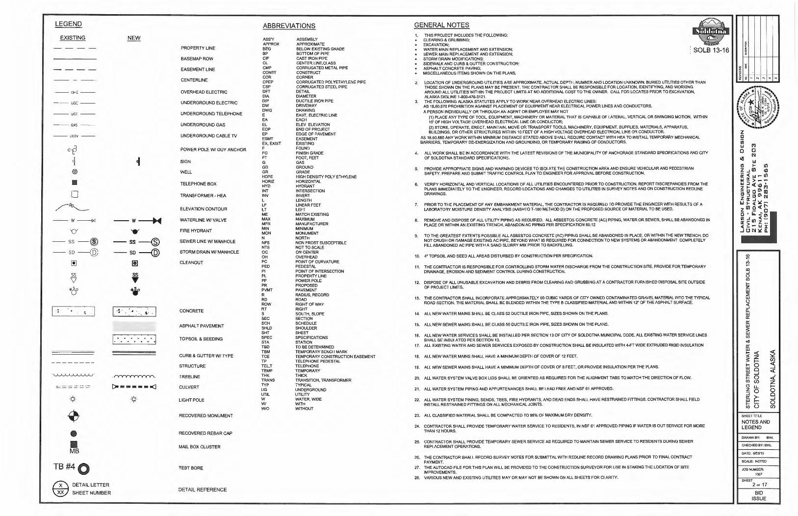
LEGEND
EXISTING
--- OHE ---
- --UGE ---
--- UGT ---
---GAS ---
--UGN
- - W-l><l
'CY
SS --@ SD -@ [!]
SS \l ~So 0
.. . .
·~
------- -- - --
• • MB
TB#40
~ DETAIL LETIER
\gJ SHEET NUMBER
NEW
-w ·~ • SS --® so-@ l!I
I.·:. . . ' ~ ..
I . . . . . . ~ +++++ +
.~.
r::i-------<l
PROPERTY LINE
BASEMAPROW
EASEMENT LINE
CENTERLINE
OVERHEAD ELECTRIC
UNDERGROUND ELECTRIC
UNDERGROUND TELEPHONE
UNDERGROUND GAS
UNDERGROUND CABLE TV
POWER POLE W/ GUY ANCHOR
SIGN
WELL
TELEPHONE BOX
TRANSFORMER - HEA
ELEVATION CONTOUR
WATERLINE W/ VALVE
FIRE HYDRANT
SEWER LINE W/ MANHOLE
STORM DRAIN W/ MANHOLE
C LEANOUT
CONCRETE
ASPHALT PAVEMENT
TOPSOIL & SEEDING
CURB & GUTIER W/ TYPE
STRUCTURE
TREELINE
CULVERT
LIGHT POLE
RECOVERED MONUMENT
RECOVERED REBAR CAP
MAIL BOX CLUSTER
TEST BORE
DETAIL REFERENCE
ABBREVIATIONS
ASS'Y APPROX BEG BP CIP CL CMP CONST COR CPEP CSP DET DIA DIP ow DWG E EA EL EOP EP ESMT EX, EXIST F FG FT G GD GR HOPE HORJZ HYO INT INV L LF LT ME MAX MFR MIN MON N NFS NTS oc OH PC PED Pl PL pp PR PVMT R RD ROW RT s SEC SCH SHLD SHT SPEC STA TBD TBM TCE TP TEL,T TEMP THK TRANS TYP UG UTIL w W I W/O
ASSEMBLY APPROXIMATE BELOW EXISTING GRADE BOTTOM OF PIPE CAST IRON PIPE CENTER LINE.CLASS CORRUGATED METAL PIPE CONSTRUCT CORNER CORRUGATED POLYETHYLENE PIPE CORRUGATED STEEL PIPE DETAIL DIAMETER DUCTILE IRON PIPE DRIVEWAY DRAWING EAST, ELECTRIC LINE EACH ELEV ELEVATION END OF PROJECT EDGE OF PAVEMENT EASEMENT EXISTING FOUND FINISH GRADE FOOT, FEET GAS GROUND GRADE HIGH DENSITY POLY ETHYLENE HORIZONTAL HYDRANT INTERSECTION INVERT LENGTH LINEAR FEET LEFT MATCH EXISTING MAXIMUM MANUFACTURER MINIMUM MONUMENT NORTH NON FROST SUSCEPTIBLE NOTTO SCALE ON CENTER OVERHEAD POINT OF CURVATURE PEDESTAL POINT Of INTERSECTION PROPERTY LINE POWER POLE PROPOSED PAVEMENT RADIUS, RECORD ROAD RIGHT OF WAY RIGHT SOUTH, SLOPE SECTION SCHEDULE SHOULDER SHEET SPECIFICATIONS STATION TO BE DETERMINED TEMPORARY BENCH MARK TEMPORARY CONSTRUCTION EASEMENT TELEPHONE PEDESTAL TELEPHONE TEMPORARY THICK TRANSITION, TRANSFORMER TYPICAL UNDERGROUND UTILITY WATER, WIDE WITH WITHOUT
GENERAL NOTES
~ 1. THIS PROJECT INCLUDES THE FOLLOWING: CLEARING & GRUBBING; EXCAVATION; WATER MAIN REPLACEMENT AND EXTENSION; SEWER MAIN REPLACEMENT AND EXTENSION; STORM DRAIN MODIFICATIONS;
: SOLS 13-16
SIDEWALK AND CURB & GUTTER CONSTRUCTION; ASPHALT CONCRETE PAVING; MISCELLANEOUS ITEMS SHOWN ON THE PLANS.
2. LOCATION OF UNDERGROUND UTILITIES ARE APPROXIMATE. ACTUAL DEPTH, NUMBER AND LOCATION UNKNOWN. BURIED UTILITIES OTHER THAN THOSE SHOWN ON THE PLANS MAY BE PRESENT. THE CONTRACTOR SHALL BE RESPONSIBLE FOR LOCATION, IDENTIFYING, AND WORKING AROUND ALL UTILITIES WITHIN THE PROJECT LIMITS AT NO ADDITIONAL COST TO THE OWNER. CALL FOR LOCATES PRIOR TO EXCAVATION. ALASKA DIGLINE 1-800-478-3121.
3. THE FOLLOWING ALASKA STATUTES APPLY TO WORK NEAR OVERHEAD ELECTRIC LINES: AS 18.60.670 PROHIBITION AGAINST PLACEMENT OF EQUIPMENT NEAR ELECTRICAL POWER LINES AND CONDUCTORS.
A PERSON JNDJVJDUALL Y OR THROUGH AN AGENT OR EMPLOYEE MAY NOT (1) PLACE ANY TYPE OF TOOL, EQUIPMENT, MACHINERY OR MATERIAL THAT IS CAPABLE OF LATERAL, VERTICAL OR SWINGING MOTION, WITHIN 10' Of HIGH VOLTAGE OVERHEAD ELECTRICAL LINE OR CONDUCTOR; (2) STORE, OPERATE, ERECT. MAINTAIN, MOVE OR TRANSPORT TOOLS, MACHINERY, EQUIPMENT, SUPPLIES, MATERIALS, APPARATUS, BUILDINGS, OR OTHER STRUCTURES WITHIN 10 FEET OF A HIGH VOLTAGE OVERHEAD ELECTRICAL LINE OR CONDUCTOR.
AS 18.60.680 ANY WORK WITHIN MINIMUM DISTANCE STATED ABOVE SHALL REQUIRE CONTACT WITH HEA TO INSTALL TEMPORARY MECHANICAL BARRIERS, TEMPORARY DE-ENERGIZATION AND GROUNDING, OR TEMPORARY RAISING OF CONDUCTORS.
4. All WORK SHALL BE JN ACCORDANCE WITH THE LATEST REVISIONS OF THE MUNICIPALITY OF ANCHORAGE STANDARD SPECIFICATIONS AND CITY OF SOLDOTNA STANDARD SPECIFICATIONS.
5. PROVIDE APPROPRIATE SIGNS AND WARNING DEVICES TO ISOLATE THE CONSTRUCTION AREA AND ENSURE VEHICULAR AND PEDESTRIAN SAFETY. PREPARE AND SUBMIT TRAFFIC CONTROL PLAN TO ENGINEER FOR APPROVAL BEFORE CONSTRUCTION.
6. VERIFY HORIZONTAL AND VERTICAL LOCATIONS OF All UTILITIES ENCOUNTERED PRIOR TO CONSTRUCTION. REPORT DISCREPANCIES FROM THE PLANS IMMEDIATELY TO THE ENGINEER. RECORD LOCATIONS AND CHANGES TO UTILITIES IN SURVEY NOTES AND ON CONSTRUCTION REDLINE DRAWINGS.
7. PRIOR TO THE PLACEMENT OF ANY EMBANKMENT MATERIAL. THE CONTRACTOR JS REQUIRED TO PROVIDE THE ENGINEER WITH RESULTS OF A LABORATORY MOISTURE DENSITY ANALYSIS (AASHTO T-180 METHOD D) ON THE PROPOSED SOURCE OF MATERIAL TO BE USED.
8. REMOVE AND DISPOSE OF ALL UTILITY PIPING AS REQUIRED. ALL ASBESTOS CONCRETE (AC) PIPING, WATER OR SEWER, SHALL BE ABANDONED IN PLACE OR WITHIN AN EXISTING TRENCH, ABANDON AC PIPING PER SPECIFICATION 60.12
9. TO THE GREATEST EXTENTS POSSIBLE ALL ASBESTOS CONCRETE (AC) PIPING SHALL BE ABANDONED JN PLACE. OR WITHIN THE NEW TRENCH. DO NOT CRUSH OR DAMAGE EXISTING AC PIPE, BEYOND WHAT IS REQUIRED FOR CONNECTION TO NEW SYSTEMS OR ABANDONMENT. COMPLETELY FILL ABANDONED AC PIPE WITH A SAND SLURRY MIX PRIOR TO BACKFILLING.
10. 4" TOPSOIL AND SEED ALL AREAS DISTURBED BY CONSTRUCTION PER SPECIFICATION.
11. THE CONTRACTOR JS RESPONSIBLE FOR CONTROLLING STORM WATER DISCHARGE FROM THE CONSTRUCTION SITE. PROVIDE FOR TEMPORARY DRAINAGE, EROSION AND SEDIMENT CONTROL DURING CONSTRUCTION.
12. DISPOSE OF ALL UNUSABLE EXCAVATION AND DEBRIS FROM CLEARING AND GRUBBING AT A CONTRACTOR FURNISHED DISPOSAL SITE OUTSIDE OF PROJECT LIMITS.
13. THE CONTRACTOR SHALL INCORPORATE APPROXJMATEL Y 60 CUBIC YARDS OF CITY OWNED CONTAMINATED GRAVEL MATERIAL INTO THE TYPICAL ROAD SECTION. THE MATERIAL SHALL BE BLENDED WITHIN THE TYPE B CLASSIFIED MATERIAL AND WITHIN 12" OF THE ASPHALT SURFACE.
14. All NEW WATER MAINS SHALL BE CLASS 52 DUCTILE IRON PIPE, SIZES SHOWN ON THE PLANS.
15. ALL NEW SEWER MAINS SHALL BE CLASS 50 DUCTILE IRON PIPE, SIZES SHOWN ON THE PLANS.
16. ALL NEW WATER SERVICES SHALL BE INSTALLED PER SECTION 13 OF CITY OF SOLDOTNA MUNICIPAL CODE. ALL EXISTING WATER SERVICE LINES SHALL BE INSULATED PER SECTION 13.
17. ALL EXISTING WATER AND SEWER SERVICES EXPOSED BY CONSTRUCTION SHALL BE INSULATED W ITH 4-FT WIDE EXTRUDED RIGID INSULATION
18. ALL NEW WATER MAINS SHALL HAVE A MINIMUM DEPTH OF COVER OF 12 FEET.
19. ALL NEW SEWER MAINS SHALL HAVE A MINIMUM DEPTH OF COVER OF 8 FEET, OR PROVIDE INSULATION PER THE PLANS.
20. ALL WATER SYSTEM VALVE BOX LIDS SHALL BE ORIENTED AS REQUIRED FOR THE ALIGNMENT TABS TO MATCH THE DIRECTION OF FLOW.
21. ALL WATER SYSTEM PIPING AND APPURTENANCES SHALL BE LEAD FREE AND NSF 61 APPROVED.
22. ALL WATER SYSTEM PINING, BENDS, TEES, FIRE HYDRANTS, AND DEAD ENDS SHALL HAVE RESTRAINED FITTINGS. CONTRACTOR SHALL FIELD INSTALL RESTRAINED FITTINGS ON ALL MECHANICAL JOINTS.
23. ALL CLASSIFIED MATERIAL SHALL BE COMPACTED TO 95% OF MAXIMUM DRY DENSITY.
24. CONTRACTOR SHALL PROVIDE TEMPORARY WATER SERVICE TO RESIDENTS, JN NSF 61 APPROVED PIPING IF WATER IS OUT SERVICE FOR MORE THAN 12 HOURS .
25. CONTRACTOR SHALL PROVIDE TEMPORARY SEWER SERVICE AS REQUIRED TO MAINTAIN SEWER SERVICE TO RESIDENTS DURING SEWER REPLACEMENT OPERATIONS.
26. THE CONTRACTOR SHALL RECORD SURVEY NOTES FOR SUBMITTAL WITH REDLINE RECORD DRAWING PLANS PRIOR TO FINAL CONTRACT PAYMENT.
27. THE AUTOCAD FILE FOR THIS PLAN WILL BE PROVIDED TO THE CONSTRUCTION SURVEYOR FOR USE IN STAKING THE LOCATION OF SITE IMPROVEMENTS.
28. VARIOUS NEW AND EXISTING UTILITIES MAY OR MAY NOT BE SHOWN ON ALL SHEETS FOR CLARITY.
I ~
I-
i - "' .., .. "
CD ~
' C') ~
co _.. 0 en I-z w ~ w ()
::s CL w Cl:'. Cl:'. w $: w en ~
Cl:'. w
;2 ~ <{ z $: I- CJ)
I- 0 ::s w Cl w <{ Cl:'. ....J I- 0 <i. en en z Cl LL I-z 0 0 ::; Cl Cl:'. ~ ....J w 0 I- u en CJ)
SHEETTITI.E
NOTES AND LEGEND
DRAWN BY: BWL
CHECKED BY: BWL
DATE: 6103113
SCALE: NOTED
JOB NUMBER:
1307
SHEET 2 OF 17
BID ISSUE

HALCYON SUBDIVISION
PHILLIPS ADDITION
TB #4 - LEFT SHOULDER 0.0' - 0.5' GRAVEL ROAD SURFACE 0.5' -8 O' SILTWI GRAVEL
NOTE NO FABRIC FOUND
LOCATE ALL UNDERGROUND UTILITIES BEFORE CONSTRUCTION COMMENCES. CALL THE ALASKA DIG LINE
LOCATE CENTER AT 81 1.
fA\ RIVERVIEW & STERLING STREET PLAN & PROFILE-WATER \..V 0' 50' 100'
GRAPHIC SCALE
STA: 0"40 00, 21.2' L ~ CONSTRUCT WATER MAIN
BLOW-OFF
I • ~ OH( I °"' ~"' \\
,--------------1 I I I I I I I I I I
'---------------'
I ~ I ~ L STA: 2+42.07, 15.4T R I ~ > INSTALL 90' BEND w1 (2)- a· GATE w I ffi VALVES, VALVE BOXES, AND
I ~ 0: ~ CONCRETE THRUST BLOCKING
I LOT G ~ 11 ~~
: RIVER VIEW ~ : U I I
II I I I I
'
""" ~
, I I llCAlJTIONll / ~ ,- NEW SSMH --- !!CAUTION!!
/ ~TA·n+"'"'"'" /
BP ELEV:74.04
(!J :8 g t; ~
"- :8 :8 :g :g (!J (!J (!J (!J w w "- w
0+00 1+00
LOT H-4
SHOUN SUBD.
~ I SOLS 13-XX
co ..-' <'> ..-
co _, 0 Cl)
I-z w ::E w (.)
~ (L w 0:: 0:: w ~ w Cl)
o6 0:: w
~ ~ <( z I- Cf)
I- 0 :5 w 0 w <( 0:: _J
I- 0 <( Cl) Cf) z C) u.. I-z 0 0 :i Cl a:: ~ _. w 0 I- (3 Cl) Cf)
SHEET TITLE
PLAN AND PROFILE
DRAWN BY: BWL
CHECKED BY: BWL
DATE: 6/03/13
SCALE: NOTED
JOB NUMBER: 1307
SHEET 3 OF 17
BID ISSUE

I 1t-I ~ 2
1ii5 I~ 1;!
~~ I ~ I ~ I I REMOVE EXISTING DIP ANO
CIPWATERMAINAND
I VALVES
I
I I I r-------1
I ~ I I I I (/) I
I US I I 7
Ii'.: I I
I ~ I I I
I ::::i I I
I ~ I I [_ ______ 1
I L _ __ .!_9'~TILITY __§.ASM'T
1--------1
I I STA: 3+78.32, 10.53' L I I INSTALL 8"x8~· TEE+ (2)- 8" : GATE VALVES ANO (1)i6' GATE VALVE, VALVE Bj)XES, : AND CONCRETE THRU~T I BLOCKING I I
I I
: 61: I I I I I I I I I I I I I
~
STA: 5+55.40, 10.53' L
~~~~~t~~~~1E)-~~~T~ I VALVE, VALVE BOXES, AND I
CONCRETE THRUST BLOCKING I
I I
1- I ~I US I ~I ::JI §1 ol
NOTE: RECONNECT ALL EXISTING WATER SERVICES TO NEW MAIN. INSULATE ALL EXPOSED WATER SERVICES WITH 2"THICKx4-FTWIOE RIGID INSULATION PER SPECIFICATION.
I I I I I l t-1 tJ5 IUS I~ I;! I~ Jo
~ >> ~ ~ >>
,l'I 5
~'~ --' "' "'
n 35.0 LF of NEW 6" CL52 DIP
ls'TA:-17S0.23.24:5·1R -----J I CONNECTTO EXl~T 6' Cl, INSTALL I NEW s· GATE VAL E. LEAVE EXISTING I VALVE IN OPEN smoN ANO LOWER I VALVE BOX 6' BE~OW FG. I I I I I I
I 49 I I I I I I I I I , ________ ,
~ ;;: w
"'"' ...:w .....
.., Ll @!!:f d ;i.-;/.
w
"' t"') ~ UJ lJJ
,;;: ,;;: 51 ""' ~ ., <n
.,,,., ... :.O!n
"''lli ~ lffi ;o, 2 '' --... ,:!f ,_I[;
0.0' -1.0' GRAVEL ROAD SURFACE / 2.0' -~.5' SILT WITH SANO /
TB '9-CENTER OF EXIST ROAD
6.5' - .0' SILT WI GRAVEL / NOT : NO FABRIC FOUND ~--+-------~. /
/
/ /
/ /
// / / /#' #'
/ /
/
STA: 7+50.23, 10.53' L INST ALL 8"x8"x6" TEE WI (2)-8" GATE VALVES AND (1)-6" --------------1 ;;bec~~~ii:;-~~~ \ BLOCKING I I
I I
l'J ;;:
"'"' ill! ... c:;
\ I I I I I I I I \ I I I I I I I I I
uJ
;: "'., d
""G
,;;: .,,u; ;ilffi
«> ,:!f
I I I I I I I I I I
_______ _,
37
;;: .,, Ii)
!41Uj
... ;i;
9
TB #2 - LEFT SHOULDER
0.0' - 4.0' GRAVEL ROAD SURFACE/GRAVEL 4.0' - 6.5' CLEAN SANO 6.S -8,0' WELL GRADED 3" MINUS GRAVEL NOTE: NO FABRIC FOUND
LOCATE ALL UNDERGROUND UTILITIES BEFORE CONSTRUCTION COMMENCES. CALL THE ALASKA DIG LINE
LOCATE CENTER AT fil.
I I I
1-------{ I I I I I I I I I I I I I I [_ _ ____ _ _I
I- I-~ ~ (/) (/) <( <( w w
~ ~ ::J ::J i== i== ::J ::J 0 0
r---------1 I I I I I I ,---J I
I I , , , , I I ---, I
: 25 : I I I I I I I : , ___ _ _ ____ _J
~ ~<( i':x ~ l;:t ~ 1;; ~ 1 :;( ;::: ;51)( i': lv r-1 CAUTION II ., z N::::, I / I < ..,,_
/ GAS
/ / - ----------·- , I\
/ I II 11 ~!!CAUTION!! \ I I
r--.... I I __ .. _, ___ ,,__ I I 11,AUTONH
I I ;'\, --- -L.J 1X WATER SER\ CE ---
'i I ~ 47.9 LF o NEW 8" CL52 llP @ 0.15%
I 177.1 LF ofNEW8"CL5 [email protected]% I 14 ,OLro '"~"" .
~ :ii "' "' iii ., :;; ~ ;::; ill q ... :;j t :;j :; :;j ;i "' :; ;i :; .,
" " " Cl Cl " " " " " 1i' w "- w "- w "- w "- w w
S! ~ S! ;::; 0 I:; 8 ::i :; ::i :; ~ ;;,i; .,;
00
" " " Cl " Cl " w "- w "- w "- w
~ 0 "' :;j '" "' ;i ., .,
" " 1i' w w
5l !il ~ ill :il "' "" ;;,i; ;;,i; i, ;i :; :;
" " " " " " w "- w w w "-
4+00 5+00 6+00 7+00 8+00 9+00 10+00
STERLING STREET PLAN & PROFILE - WATER o· 50' 100'
GRAPHIC SCALE
"' z Q
~ "'
I ~
i - "' .., .. "'
<O ..--~ ..--CD --' 0 Cl)
I-z w :!E w ()
:5 CJ._ w 0:: 0:: w ~ w Cl)
o6 0:: w
~ I-w w 0:: I-Cl)
('.) z :::i 0:: w I-Cl)
M D l\l
<( z ~ 0 0 _J
0 Cf)
LL 0
~ u
SHEET TITLE
PLAN AND PROFILE
DRAWN BY:
~ Cf) <( _J
<(
<i. z ~ 0 0 _J
0 Cf)
BWL
CHECKED BY: BWL
DATE: 6103/13
SCALE: NOTED
JOB NUMBER: 1307
SHEET 4 OF 17
BID ISSUE

I I
I
I I
I I I
I
I I I
1D+81.25 NEW WATER SERVICE
~- ..SS---"' I os --a<--os
J I
I r----I ---I --, I I I I I f I I ,---J I
I I I I I I
I ,_ __ I
I I I 25 I I I I I I I
I I I I I -----____ .}
10\ ~ /) Ill j~ m "' r ~ c
G) )>
~ fTI
10
STA: 11+32.98, 10.80' L INSTALL 8"Xll"xfi" TEE WI (2r 8" GATE VALVES ANO (1r a· GATE VALVE, VALVE BOXES, AND CONCRETE THRUST BLOCKING
STA: 11+32.98, 24.9' R CONNECT TO EXIST 6' AC, INSTAU. NEW 6" GATE VALVE ------- -1
I I I I I I
: I I I I I I I I I I I I I I I I
NOTE: RECONNECT ALL EXISTING WATER SERVICES TO NEW MAIN. INSULATE AU. EXPOSED WATER SERVICES WITH T THICK x 4-FT WIDE RIGID INSULATION PER SPECIFICATION.
100
I:; 0
...J ' ~ 1 A
.,.; ~~~~
a:'-' -.,,55 "·°lllLJ W
"'"' . ~~ a>Z :- < ~(o
90 G >< ~·~N~ r EXIST C ELEV
/
-- - .,£.,_
:.· - - - -fl II
:: II
·" 80
- .J
\ \ 70
\ ST : 11•32.98 BP ELEV:71.97
65 ;;
~ ~ 0 "' .; :; "1 "! ., :3 ::l ;! (!) f2 ... (!) (!) (!)
uJ w UJ
11 +00 12+00
STERLING STREET PLAN & PROFILE -WATER O' so· 100'
GRAPHIC SCALE
TB #1 · LEFT SHOULDER
0.0' • 2.0· GRAVEL ROAD SURFACE 2.0' • 8.0'WELL GRADED 3" MINUS GRAVEL NOTE: ND FABRIC FOUND
I i-1 ~, (/J
i'.li l
13 ~I ::i i §1 ol ..... ,
I
1- CLFlNISH , I
I I
-JJCAUTIONll -w• ~"
··- --.. .. ··--
STA: 1 +30± -IX2"WATERSE VICE "
... - · · ·- -- ... -·
ll: ~ ~ gi 3l g g &l ..; &l ., (!) (!) (!) (!) f£ UJ ... UJ UJ
13+00
11
!:-~ (/J
i'.1i
~ ::::i ~ :J 0
GRADE
'h
;:;;p-,.;, U ,DO"'o
ill :;j (!) UJ
LOCATE ALL UNDERGROUND UTILITIES BEFORE CONSTRUCTION COMMENCES. CALL THE ALASKA DIG LINE
LOCATE CENTER AT~- ~
, --------- ---1 J I 5.0 LF of NEW s· CL52 DIP I I I I I I I I
'- -, 1 l I L-- - , I I I I I I I I I I !._ _ ___________ _J
C'TA• Hi+""" ~ ... ~ CONNECT TO XISTING TEE AND INST L 8° Uf'\l~Vl'\I...,~, ,.,,,, ...
- - --- - --3 .7 LFof NEWt "Cl52 DIP t@ 7.99%~
STORM RAIN CROSSIN PROVID DUAL WALL v ... ~ n.>.>.Hn1._1·, 1rl<' . " ·
" " I'.
i SOLB 13-XX
1_2~:,.,._~±=~-t-;- SAWCUT EXISTING ASPHALT ANO REMOVE AND
\ \ \ \ .,
I ----\ \ .,
\
~
" -' '.AllP"
' -P7f Y / /
REPLACE FOR WATER MAIN CONNECTION. REMOVE EXISTING CONCRETE VALLEY GtmER AND REPLACE TO ORIGINAL GRADES
STA: 15+34.0 t. 6.6' R CONNECTTO EXISTING 1o·x1o·xs· TEE, INST AU. 8"GATE VALVE, VALVE BOX AND RISER. INSTAU. (2) • 45' FITIINGS AND THRUST BLOCKS AS REQUIRED
100
90
80
PROVIDE 4" ;iiKx6'W INSL ATION- 7 /7 -~- STA: 1o'11 T 15+36 I / / I
'' {/ 7 ~•NU 70
/ Tl>
STA: 5•03.00 / BP EL V:69.54
65 18 "' i!l gi ~ i;i
., <'i <'i :;j (!) ., ., ., ...
(!) @ (!) f2 @ ... UJ
14+00 15+00
CD ~
' <') ~
DD ...J 0 CIJ f-z w ~ w (.)
::5 D.. w a:: a::: w ~ w CIJ ~
a:: w
~ f-w w a:: f-CIJ ~ z :J a:: w f-CIJ
(")
0 N
<( z I-0 Cl ....J 0 Cf)
LL 0
~ 0
SHEET TITLE
PLAN
;2 Cf) <( ....J <(
<i z I-0 0 ....J 0 Cf)
AND PROFILE
DRAWN BY: BWL
CHECKED BY: BWL
DATE: 6/03113
SCALE: NOTED
JOB NUMBER:
1307
SHEET 5 OF 17
BID ISSUE

HALCYON SUBDIVISION
PHILLIPS ADDITION
LOCATE ALL UNDERGROUND UTILITIES BEFORE CONSTRUCTION COMMENCES. CALL THE ALASKA DIG LINE
LOCATE CENTER AT fil.
I ----1-------------------- -- -~-------------------
I 1 O' UTILITY EASM'T I :------: r-------1 I L----1
I I I I I I I L _____ _
1
I I
---------
EXISTING 10" AC SEWER MAIN TO BE ABANDONED I WITHIN TRENCH FOR NEW SEWER. A LL WITH I GROUT SLURRY PER SPEC
LOTG
RIVERVIEW
NOTE: RECONNECT AU EXISTING SEWER SERVICES TO NEW MAIN. INSULATE ALL EXPOSED WATER SERVICES WITH 2" THICK x 4-FTWIDE RIGID INSULATION PER SPECIFICATION.
llCAUTIO 11 / GAS UTIL TY
n
1ii' / I
::: ~ !!, 0 ;: "' ,..- EXIST CL ELEV :>. i'l .,;
..- c.; co ~ / r-CLFINISH GRADE '"';"' ~ ~ .:....:
"'"' °' I= I GAS UTILITY -I
I
---------------, I I I I I I I I I I I I 1 _______________ 1
--~- EXISTING 10" AC SEWER MAIN TO BE ABANOONED WITHIN NEW SEWER TRENCH. FIU WITH SAND SLURRY PER SPEC 60. 12
SSMH· (2) STA:2+44.34 OFF:32.05R RIM:86.40 INV IN:75.20 INV OUT:75.10
REMOVE EXISTING MANHOLE
---- !!CAUTtON!! CABLE TV
1 O' UTILITY EASM'T
10' UTILITY EASM'T
LOT H-4
SHOUN SUBD.
80;--~~--,1-~~-1-~~~t-~....--+~-t--11--t-~~-1~~~-t-~~~~/--r-/~~t-~~-+~~~-t-~-+++~~~-t-~~---11-~~-1-~~~r80
.;1- - - I U lt"fQ'.l .:irl% I t;:C ") C • • ·• •n• ,.., rn ,..,, .-=.. ,.
II · ~~ - - -
NEW " DIPWATER -._,... MAIN
70;-~~--r~~~-t-~~-t-~~~1-~~-t-~~-1~~~-t-~~-+~~~t-~~-t-~~---11--~~-1--~~--r~~~-t-~~-1-~~--t- 70
RIVERVIEW & STERLING STREET PLAN & PROFILE - SEWER o· so· 100'
GRAPHIC SCALE
0+00 1+00 2+00
l8 g C) w
3+00
SOLB 13-XX
co ~
' ("') ~
!Xl _J
0 (/)
f-z w :2 w () ~ _J
11. w 0::: 0::: w ~ w (/)
~
0::: w
~ i ~ z I- Cf)
f- 0 ~ w Cl
_J
w ~ 0::: _J
f- 0 <i (/) Cf) z (!) u.. I-z 0 0 ::J Cl 0::: ~ _J w 0 f- 0 (/) Cf)
SHEET TITLE
PLAN AND PROFILE
DRAWN BY: BWL
CHECKED BY: BWL
DATE: 6/03113
SCALE: NOTED
JOB NUMBER:
1307
SHEET
6 "' 17
BID ISSUE

90
I 1t-I~ 1U5 I~ 1;! 1-
i=J I ~ I I I I
2 r-------1 I I I I I I I I I I I I I I I I I I I I I I
STA: 3+96 CONSTRUCT NEW SEWER SERVICE
I I I I I I L._ ______ 1
REMOVE EXISTING MANHOL
SSMH-(3) STA:3+87.39 OFF:6.13R RIM:83.74 ,--------1 INV IN:75.15 I I INV IN:74.62 I I INV OUT:74.23 I I
CONNECT TO EXISTINcJ 10" AC : SEWER I I
I I I I
: 61: I I I I I I I I I I I I I I I I
7
NOTE: RECONNECT All EXISTING SEWER SERVICES TO NEW MAIN. INSULATE ALL EXPOSED WATER SERVICES WITH 2· THICK x 4-l'T WIDE RIGID INSULATION PER SPECIFICATION.
~ I~ u. ,2 ;;; N ('! "''~ ........ ·:: ':-: .-' .-'a:
+ti ·;; ~ ~ ~<
" <~ > > <( <I~
tl)(/)0::: "'"' U)
--I
!!CAU [ION!!
77.4 _ ....
I I I I I
t-1 ~I LI) I ~I :JI ~I c l
I I I I I lt-1~ I LI) I~ I;) I~ lb
EXISTSSMH 1 STA:5+68.73 OFF:7. 79R RIM:84.10 INV IN:76.15 INV OUT:76.05
n ,-------1 I I I I I I I I J I I I I I J I
I 49 I J I I I I I J I 1 ________ J
OJ m ~ z G)
?< m
w
~
''"" ~ii::U
<'! w
""" ~
a: w m;ij m< (/) . ~ !:: 0 / - CUJ!C:.Ul'!D61hC C::, l(tj !!C lJTION!I\ +-ti . :;,
~x .. -... ~ ~ ... z z I ~ I~ ~fCAUTIONU \ !:a<i.~ .;
X WATER SERI CE---..._ c-- NEW e· DIP WATER MAN
-- - ----- - ----, __
11:1 ·-
.. ..., ,n11vn vnr.•1v1 , ,, -~ NEwa•OtPVt.~TER MAIN
N "' ~ 0 :ll :e "1 m ~ 1' "' "' M ::l :;i :;i M ;i; m ;i; ., ;i; ;i; .. ;i;
" " " " " " " " " " w u. w u. w u. w u. u. w
S! ... S! ll! ::i ;:! .,; ;i; "' " " " " w u. w u.
4+00 5+00 6+00 7+00 8+00 9+00
STERLING STREET PLAN & PROFILE - SEWER o· so· 100'
GRAPHIC SCALE
·-
-
10+00
CD ~ . C') ~
cc _J
0 (/)
I-z w :::: w () <( _J Q. w O'. O'. w ~ w (/)
o15 O'. w
i I-w w O'. I-(/)
Cl z :J O'. w I-(/)
C'l 0 [lj
~ z I-0 0 _J
0 Cf)
LL 0
~ 0
SHEET TITLE
PLAN AND PROFILE
DRAWN BY:
;2 Cf)
~ _J
~
<i z I-0 0 _J
0 Cf)
BWL
CHECKED BY: BWL
DATE: 6/03113
SCALE: NOTED
JOB NUMBER:
1307
SHEET 7 OF 17
BID ISSUE

I I
I I I 10 I
I I I I
I I I I
11 LOCATE ALL UNDERGROUND UTILITIES BEFORE CONSTRUCTION COMMENCES. CALL THE ALASKA DIG LINE
LOCATE CENTER AT fil.1.
I I I
I SERVICE I I /(~~~~r : 1f I
I : q ; . I ~~ •••• A A A A A A-::,__• .. ~ A A ----1=. ~, -A A -- ·- A~ A. • • A __ ...... - h 5'UTILITY EASM'T ;¢: =------- -.: 1on ~ 1\, } J ~ 1
,_ 'l ·-- . .....L _ J ... ,-. ·~ ,,_ ·- '"" • ~• - - ;;:; - "" ~ •- ·- oh • • A A J!)n --- '1311 '"" :_ ...J. ~ ';! I
N--132Q;27"l~- -= TB#:~+----~ t-:r-------------""TB#1':'~'--""'-~--- 'I_ A•• A J_ --0--t_ ~~i~-; Fin =/:~ • "' 0 1±:1: --- ---- ~\ .~ I I >:.X - -----= -W-0- • JN------lW#--~- W * ft -W- -W -w ---w------- W"' W- - --r------y ---- W P
>-•-- •-fi- . _£_9_~~ .-- J _____ 8".c1 (198~-- ~_J. •--• •- - ir-- •--•- -• 8" AC•~•--•--•--•-- •--• 1- -•--•--·-· \ [1 ~ ! \ -----+--r -- -101oo--- --+- I 11 00 - -+-y---- 12±00 - -- - &STERLING ST 13!00-- t(- -I-- - -- -1~----.----=-. ;- ._:::_--:;:; ;.j./;\ '!O ~~40 ~~~-::-~\ os=c.--r '1i·~~U·~ .SS ;--is -=--.---~ .. __. c-
50 -i/--~~---..-= .. =--.s=--..---~=-~~M~_:s~71:~)--..--=tt o;==--.. --;-=:=:.-.. --~-.. -:;;--~;--;=!.±~ ~-±.~ i· ~I '1
I I <a.'\ 'L "' 1 c:.s-- c:.s--c:.s--c:.s--c:.s-- "' --c:.s --c:.s-- Mrr-....,- /1 ~' I Il l ! ,/ ,__,__ .. _ .., i. f 1t ; . 1
.--v v - v \/,' ~ •i
I ,-------{ :---------, \ J ( . --~ (' ~f I I I I I I la: ~ 1 ~ . I
I 1 I I :::0 l \ ! ! i"> OJ --------1 I 1------------1 m i
I II l 1---J I ·,~ PJ t-1 t- I I 0 I I I I I I .:e, C ~I ~ I I CQ
I I I : Cl) Cl) I I t-1 ~ ----- --- : I ~ LD I LD I : OJ
~I w~ - --, 25 / ~< ~ I ~ ' --1 1 : ~ '1
LD1 I I 13 :JI :J I •- --,, < ~ >- I I [Tl - - I m I I- I : ~ I ~ I : • I
§: § :__ _______ J ~: ~ L __ _______ ___ J I ~I ~ I I
NOTE: RECONNECT All EXISTING SEWER SERVICES TO NEW MAIN. INSULATE ALL EXPOSED WATER SERVICES W1lH 2" THICK x 4-FTWIDE RIGID INSULATION PER SPECIFICATION.
I I I
100+--~-r-~--+~~~T""""~~-+-~~-.-~~--+~--.,....----+----.-----",__ __ .,....----+-----.-~-___,,__ __ -..----+-----.----1----~-..-~~-+ 100
N
(/) I- ..
90-+-- --+--+---+-- - +----+----+----+---+-----+----+----",__ _ _ +-----+----+- - -,__--+--->--l-----+---1------t----+ 90
- --- ---- ------ -----4 n
II
/ r EXIST Cl ELEV
- ----
- NEW e· DIP ~ATER IMIN
-- - ~--- -
I I
I
I~ CL FINISH !>RADE
STA: 1 •30t -I X 2" WATER SE VICE "-
----
,,,
65+----+---+-~~-+---~1--~~-+-~--1----4------4----+----i-----l---4----4----+---~-+-~---11-----'1---~-l-~~~4-----+- 65
ill ~ :;: Oi :;: "' :s ... ~ ~ ill ::i a ~
~ lll :g ., ~ "': "! ;i :;i
... :3 ... :ll ... "' ;,!; ;i ;,!; ::! :;i :;i N oi :;j :;i " ... ... ... ... LL
" fr " fr " fr " " fr " " " " fr fr fr " " " @ "' "' "' "' LL "' w LL "' LL w LL
11+00 12+00 13+00 14+00 15+00
(A\ STERLING STREET PLAN & PROFILE - SEWER \.V oliii· -~~so~· ;;iliiijiiiiii1100·
GRAPHIC SCALE
SOLB 13-XX I H ~
~
~ - ... .., .. .,
CD ,... ,:, ..... al _, 0 (/)
I-z w ::E w u <( _, Cl. w c::: c::: w ~ w (/)
oa c::: w
~ ~ <( z I- (j)
I- 0 ~ w 0 w <( c::: ....J I- 0 <(-(/) (j) z Cl u. I-z 0 0 ::::; 0 c::: ~ ....J w 0 I- (3 (/) (j)
SHEET TITLE
PLAN AND PROFILE
DRAWN BY: BWL
CHECKED BY: BWL
DATE: 6/03113
SCALE: NOTED
JOB NUMBER: 1307
SHEET 8 OF 17
BID ISSUE
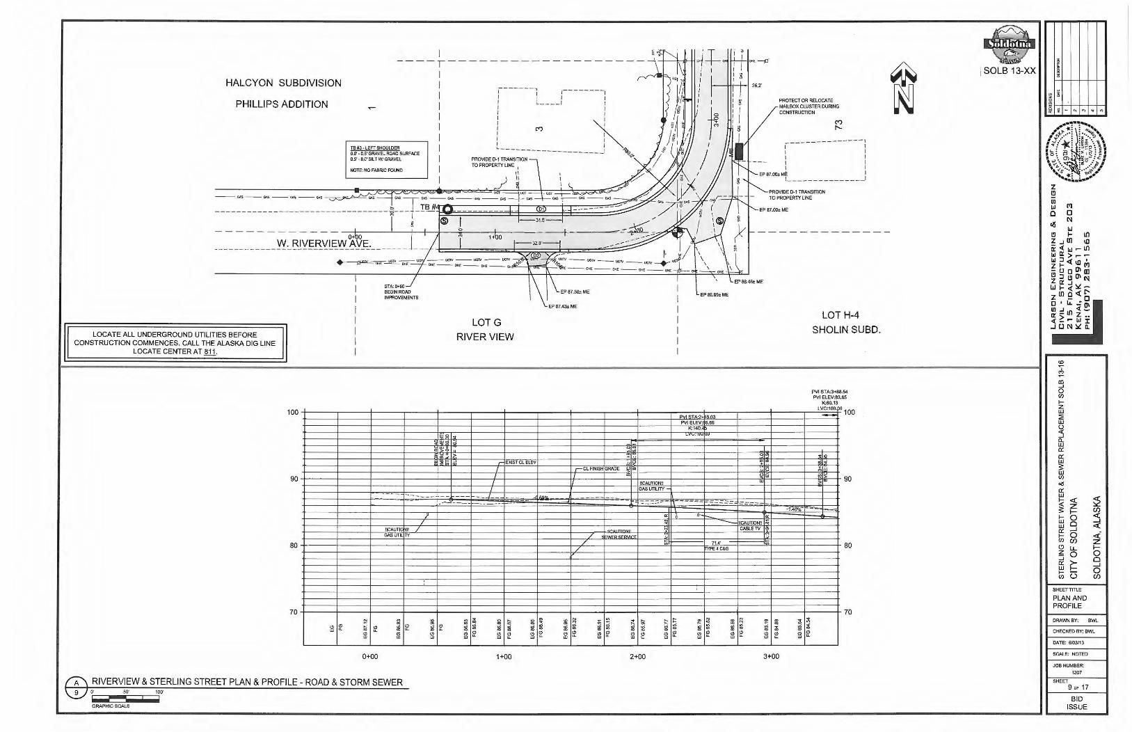
I ----,----- - -------------
HALCYON SUBDIVISION
PHILLIPS ADDITION
TB #3 - LEFT SHOULDER 0.0' - 0.5' GRAVEL ROAD SURFACE 0.5' - 8.0' SILT WI GRAVEL
NOTE: NO FABRIC FOUND
O+ W. RIVERVIEW AVE.
LOCATE ALL UNDERGROUND UTILITIES BEFORE CONSTRUCTION COMMENCES. CALL THE ALASKA DIG LINE
LOCATE CENTER AT fil1.
100
70
"' w "' "' "' "'
0+00
STA: 0+60 BEGIN ROAD IMPROVEMENTS
---
llCAUTIO II /
"' 01
"' :8 "' "' w
RIVERVIEW & STERLING STREET PLAN & PROFILE - ROAD & STORM SEWER o· so· 100·
-~~~ GRAPHIC SCALE
)'
/
ill :8
"' w
1
I I I I I I I I I I
"' u..
r ------, ,-------, I ! I I I ;_ ____ J I I I I I
I I I I
i (') ~I I I
--------------------' ~
LOTG
RIVERVIEW
"' + --
EP 86.69± ME
PVI ....... 'l.·'>+L.r ......
PV1 ELEV: 5.86 1\ :140" 5
PROTECT OR RELOCATE MAILBOX CLUSTER DURING CONSTRUCTION
-------- -----1 I I I I I I I I I I
EP 87.001 M~ i '---------------
PROVIDE 0-1 TRANSITION TO PROPERTY LINE
LOT H-4
SHOLIN SUBD.
PVI ST A:3+88.54 PVI ELEV:83.65
K:60.13
LV:=.po 100
r- EXJST Cl ELEV ·· O ';' 1':"' a;i --i I ,-CLAN1SHGRADE !,/a> .. o :, ,;;
7 GAS UTILITY -__ _f
! ll1 ~ "' ~ :8 iii :8 :8 "" "' ~ "' u.. ~ ~ w
1+00 2+00
- - - ,---~-- -==-..:= =-=----a: • a:
--- !ICAUTION!I Oi CABLE TV of>
:g l!! :8 :8 "' w "' w
O> 01 ;!
"' u..
3+00
;! ~
~ i "' "' u.. w
70
SOLB 13-XX I ~
~
i - .. .., .. ..
(!) ~
' C')
fl) __J
0 (/)
I-z w ~ w (.)
:5 0... w a:: 0:: w s: w (/)
«! a:: w
;2 i <( z I- (f)
I- 0 :5 w 0 w <( a:: ...J I- 0 <i (/) (f) z (!) LL I-z 0 0 :::i 0 a:: ~ ...J w 0 I- (3 (/) (f)
SHEET TITLE
PLAN AND PROFILE
DRAWN BY: BWL
CHECKEO BY: BWL
DATE: 6/03113
SCALE: NOTED
JOB NUMBER: 1307
SHEET 9 OF 17
BID ISSUE

2 ·-------1 I I I I : I I I
: 7 I I I I RELOCATE I SIGN I L_ _____ _
EXSDMH STA:3+93.68 OFF:14.47R RIM:84.05
32.0LF of NEW 15• CPEP@ -0.50%
1--------1 SSCB2 I I STA:3+57.87 OFF:18.35R I I RIM:84.50 I I SUMP:79.28 I I INV IN:B0.78 I I
I I I I I I
\ 61: I ! I I I I I I I I I I I I I
PVI STA:3+ 8.54
~v1 tctv: ··•• ....... .,,
ADJUST SSMH TO FINIS GRADE. EX RIM ELEV= 84.1
TB #3 - CENTER OF EXIST ROAD
0.0' - 2.0' GRAVEL ROAD SURFACE 2.0' - 6.5' SILT WITH SAND 6.5' - 8.0' SILT W/ GRAVEL NOTE: NO FABRIC FOUND
n 10.7LF of NEW 15· CPEP@ 0.50%
1-------1 I I I I I I I I I I I I I I I I
l 49 : I I I I I I I I , _______ _ J
I I I ~- ------------1 I 2 l I l I : ' ~---1 r ---sDceJ ____ i
I STA:7+17.26 OFF:-14.SSL R IM:84.43
I SUMP:78.95 INV IN:B0.45
~ OJ m :::u z G')
~ m
/ /
/
/ /
/
9 \ /////~ \ /
\ // ,,
" I
! SOLB 13-XX / /
/ r:================================·::;i I I /
/ /
LOCATE ALL UNDERGROUND UTILITIES BEFORE CONSTRUCTION COMMENCES. CALL THE ALASKA DIG LINE
LOCATE CENTER AT fil.1. I
I
// / / ~.ef'
/ ?'
24 C~P SD 1
--------------, I I SDCB4 __ _ ___ , I
STA:7+76.2g OFF :25.64R I RIM:84.89 I I SUMP:78.Q71 I INV OUT:79.}7 \
I I l I -------J I I 37 I I I I I I I I I I I I I I
I
ADJUST SSMH TO FINIS GRADE. EX RIM ELEV= 84.0
I I I
1-------{ I I I I I I I I I I I I I I L ______ J
I I
I
r---------1 I I I I I I ,---J I
I I I I I :
'---1 I .------------~ I I I 25 I TB #2 · LEFT SHOULDER
0.0' - 4.0' GRAVEL ROAD SURFACE/GRAVEL 4.0' - 6.5' CLEAN SAND 6.5' - B.O' WELL GRADED 3• MINUS GRAVEL NOTE: NO FABRIC FOUND
t"VI \:tln11u +ou • .s1 "YI--· .~- • .>
\Ir" lnnlV'I
I I I I I I I I '---------...!
90-t-----r,..,,...,,...,.--t-----t---v;"'~w:--t-----+-----t----l-----+----+-----+----+-----t----l---,-;--+-----!~;;itt1~i!----+----+-----t----l-----+-----t-----+----t---~~irt""m ___ -r----i-----t----;- 90 ............... .i&. u 1[i SDCB3 "'' 1 u.
80
Iv ··- -:._.v ll.J STA:7+17,2 OFF:·14,55L
I INV IN·ao 78 \ \ ----- -~"' -~ '' =r-;;,- --..l
:;,,..ll't· ....... _ -.. ·.. "'' \ ':,;~i..--·.--+----.f!dllc----+----+-----t----1-----+----+-----+----+-----1----1;----+
• , , ... : ~_. ··-~1 :1\~,\-\· -- -_-_ ~---·:::j ::-:-:-::·:::-: ::~-:-:-:-.1 .. -.-.-... :~ .. -~ ~- : ... :.:.~-~:_._:_~._:_·:.: :::-:.-,: ::.;_-_-_ ._._ .r ;,·-.,-.--. · __ . _ _._. _ _-_ _-J_: _ _-_:.-_ _-_-_:.-_ _-:.--_·: . .-_: _ _-__ :-_:-_-_· :_-_:sx_-_-_j __ s_._.r_ .-_-t_~_~_-.-_.lz_: __ ~~_-:_-.t.M __ : P_·_._. __ ~:.·J._·-_-:_--_._.-. ·:_-:: :-.. -.:·-.~· _· -_-_-.~- ' _ _-_·_- '., _' ___ · ·_-__· _: _ _._-_ _._ _ _. __ -_.-:.:.= _ _._-_-_-_' __ ':.'_-._'_ :_.)_~l_:.~!_t~ ~.L~-.--~---- · ~\:. -- · · -- -- -- -- ---· --- -- -- - · ·--· ---- · ·
-=-- - -":'-= ---=-= -= - - --~ I
\ ! ! -•ve• w om ~IM : ., . ..... . .. : ... :
1i~ f\.-.\.:.:.·._ :_- :-.::.: .:,:, -._-; __ '_,.;;;;.-.-;_-_-_-::-. .-;.~-.-:: ~-----: ----~~--~~·::··::--~:·:-.:.}.::::_: .. '. .:'.. :<.-.:;~g!~!!~~~~~-~--e~::::~'.--'.'..:'~'.--':--r~--~:---::---:-~~:-·:.:: -:: :~ .. ::::· .. . \ 26.1Lfof EW24"CPEP ii)-0.50%-' L i \ \ L 32.0LF o NEW 15" CPE I® -0.50% \ \
~ ADJUi T EX SDMH \ \. - ADJUST EX ~ DMH ~IM" "U \ RIM1 0FG
\ SDCB4 \ STA:7+76.29 OFF:25.64R -," .• , :~.o~
80
65 +--~~-1-~~--+~~~1---~~+--~~-+~~--1~~~+-~~-1-~~-+~~~1--~~-1-~~-1-~~--1-~~~1--~~-1-~~--+~~--+~~~1---~~-1-~~-+~~--1~~~+-~~--t--~~-+~~--ir-~~+-~~--r-~~-t-65
4+00
t; ; :i -(!) Cl Ul ""
~ :i "' 'l
QI (!) (!) w w
5+00
STERLING STREET PLAN & PROFILE - ROAD & STORM SEWER o· 50' 100'
GRAPHIC SCALE
q ::l
0 "! QI
Cl w Cl w
6+00
"' ::l "' "' ~ 'l :i 'l 'l OI OI ... QI "' Cl (!) Cl (!) (!) w "" w Ul u.
S? ~ ~ ::i OI QI (!) Cl Cl Ul ... ""
7+00 8+00 9+00 10+00
"' ~ ~
g
i
<D ~
,;, ~
ID ..J 0 (/)
I-z w :2 w ()
~ ll. w a:: a:: w ~ w (/)
oil a:: w I-<(
~ I-w w a:: I-(/)
(9 z ::J a:: w I-(/)
- "
!')
0 N
<t: z f-0 Cl ....J 0 (f)
LL 0 >-f-(3
..,
SHEET TITLE
PLAN AND PROFILE
DRAWN BY:
~ "'
~ (f)
:5 <t: <i z f-0 Cl ....J 0 (f)
BWIL
CHECKED BY: BWL
DATE: 6/03/13
SCALE: NOTED
JOB NUMBER:
1307
SHEET
10 OF 17
BID ISSUE

I I
I I I 10 I I I
I I I I
I I
11 LOCATE ALL UNDERGROUND UTILITIES BEFORE CONSTRUCTION COMMENCES. CALL THE ALASKA DIG LINE
LOCATE CENTER AT ill·
I I I
I I TB " - LEFT SHOULDER I I STA: 11+60 I 0.0' - 2.0'GRAVELROADSURFACE SOCBS 1
I REMOVEEXISTINGW 2.0'-8.0'WELLGRADEOJ- MINUSGRAVEL STA:14+74.790FRFl:M-1 •. 98.258.7L1~ o- I I I CMP STORM DRAIN PIPE I NOTE: NO FABRIC FOUND I SUMP:75.06 •
; ~ .. -:--~1~ ~-·:: -~ ·- ·- . . _ _ ~--::: _ '7 -~ - _ 5'UTILITY~MT . _# ~ _ = ~=- ~ J;~ ii 1 -=------=- -+--- ---- ---------""'~~ ..... -:·=-""'--""'---=-H-i---- "-A A A~-• _)_ Lt-uo\-~ ·, =~ I l - 1 1 ~~~t~~EW24"CPEP@ -0 .49%- & \,m -7 .- 1--1
I SOLS 13-XX
· --. __ a·. t1 (l98~ 1 _. •--•--• · ·; ~-· ·~--·--7--• a· ~c7( 1974) , __ 7 __ -.--:'--•--~-{LJ __ : __ •---~-. " " ~ W \ ;' ~ • I 1 ! -----+- - --11to-o - - - 3;-- -+--r-----1 2i~----=---~:_~T§~!-l~~§~~1~E~24·~!@ 0.2~ -1-- - -- -1~--.--=--;-~.:--=:- -~:!! ~ SJ5140V:
--;;$__ .SS- - -------- "" -a.-~os._..,,...,_ ., _as-"' - "' . M - -_--+:V=----_:-------------------- ---j . '-L _____ I .• )~ II : ""'! SAWCUT EXISTING ASPHALT ANO REMOVE ANO REPLACE FOR WATER MAIN CONNECTION. REMOVE EXISTING CONCRETE VALLEY GUTTER ANO REPLACE TO ORIGINAL GRADES
-j--1' -----:-::-::-::::-::::=,,-,-,,----:::,,......,-~ L ' ~""' - - ""'-- c.s - - "" -- ""' --... ---=--- ... __::::_: :..---:__ "° ~ ..,-..,-- ... -- ""' -- °" --°" ~~-TF t-- ,.;·~ .---1-f-J / r-~~~'t:i~~~ H--os ~ \ AOJUSTSTORMORAIN f 171;.--.l -- v v v - v \ /'~/ f I
, / -----/ II": ;:E \ :4s~G, TYP. ALL J : sTA:14+73.040FF~~~~ ~ -« t ;:ET I / f 1 RIM:82.55 ;lJ : : 10 c:D -------- I I r - - SUMP:75.40 m I
,---J I ·1~ PJ t- 1 I t- I --------- -: l~N~~:~~:: 0 I I I _,:_ c ~ I I ~ I I INV OUT:76.90 0 : : - G) (/) Cl> I I C
'---,I 25 I ~ ~ : : ~ 1--, 1 ! ~ '1 < 13 !::; I I I- I L ---1 )> I f m ....I ::i I I < ' ,' i'.=1 I i'.= , ' m I ::> ::> I f I
I I I I , , I / _________ _} o O I f ..- I I ..- !... __ _ _ _________ ,
I I I I I I
t'VI ~1n 1 1v...-...u.;Jl
·\II"· iN\ 1\1'1
;:w
90+----+-----1-----1----ifflW."-----+----+----+---~-+-----+-~~--l----+----+----.+-~--+-----+-----l---••~-Hi-~----+----':'~+-*-l----+ 90 > - • >
r EXIST Cl ELEV
/ -'=--- ----~- - ,, __ _ ------
! I
I I
------ -I
I
I
~CL FINISH t;RAQE
lt.;AUllvrm r--
-----------I I
80 - , ., : :~: :: ·. ·:}~¥.q~:·£~~c:::;-- ·:::::::1·::::::---:::=11;~1-1+. .: :.~-.:_:~._._:=:_:'"':. "':: ""·::"'::"":;,"':_.:"'·::=-; tr -,, :,..,·:,..,_:=-;.-,-=-: "':::-=.:tf,-·~--: .--. '. :"'.~·.,,,.::"':~..,. .. ~·t-:-_:,-: ::--...... --._ .. _:.--.. _:_---.-._:--_.--_._'.t-l_~~--._--.--~.· --G--v'_-~-----~ .. Nis--.·~·--_·: •• ·--.:-.·1.1-:··.·--30 •• :--•••• --_-.·.-::·_.-.-:::_:-0·.:·"".:·.··"' '_: ;r-.__:·-.·.-.:-.·--.-.-.:-·_:-.-.-.. ·--_' __ ---_,_.-t-.;- ._-.--. =_---= .. ----.:_.--,.,.~--. ,_ .. ·--.-__ -t_. • •• --.~---... ·!s--._,!_,--.-~_'.---.~.:-_--!<_,--f,l_·.!'-t:_·i---.-----·_.-_----_-:·--:-.~--:· '.--•• _--~·-t:.~·--.'..-._.--'.._s.-D._.-.M:·-H-.-.--:,· -t.' •• ----__ ---_._---_ _./ .. --.---.-.-_.-t·. Ht_--__ --___ ---+1t-1>----r- ---i- 80 ~., ~ . ·_·_·· _._ .. _:_:·:: f ~- _: .. :,::::::;;r;:;, :;::
IX Z- WATER SEI VICE '-.. STA:14+73. o OFF:13.70R / I I v
.......... :.,.;~ f N OUT:76.90
70 ;----;1----t-~--+-~~-+-~~-+--~--1~---+----t-----+----+--~-+~~--+-----1----+----t--~--+--~-11-~---+~---+---~--t- 70
65
"' 0 ... a; ... ~ "' ::i ... "' .,; .,; ~ ~ ;i; ., Cl
., iii .. Cl Cl Cl ~ w .. w
"' ~ ., re .. ~ ~ 8l :ii "' "' i "l ;i; ;i; :;i ill :;i &l N <'I
Cl fl "' .,
Cl Cl Cl Cl Cl Cl ~ Cl .. w .. w .. w w w
11+00
(A\ STERLING STREET PLAN & PROFILE - ROAD & STORM SEWER
\2V or;· -~~soiii· -iliiiiiiiii1iiloo·
12+00 13+00 14+00 15+00
GRAPHIC SCALE
I ~
.. ~ ~ ~ 'ii - ... ., .. "' "'
<D
.,:, ~
al __J
0 Cl)
I-z w ::E w (.)
:5 Cl. w a:: a:: w ~ w Cl)
oil a:: w
;2 i <( z I- Cl)
I- 0 :) w 0 w <( a:: _J
I- 0 <i Cl) Cl) z (9 u.. I-z 0 0 :J 0 a:: ~ _J w 0 I- (3 Cl) Cl)
SHEET TITLE
PLAN AND PROFILE
DRAWN BY: BWL
CHECKED BY: BWL
DATE: 6/03/13
SCALE: NOTED
JOB NUMBER: 1307
SHEET 11 OF 17
BID ISSUE

NOTES:
1. CUT EXISTING ASPHALT PAVEMENT BY SAW.CUnlNG. PROVIDE TRANSITION FROM EXISTING DflJllEWAY TO NEW BACK OF CURB. All GRADING, LEVELING COURSE, ANO ASPHALT SHA1.L BE INCIDENTAL TO RECONSTRUCT DRIVEWAY l1CM.
2. RAISE EXISTING CLEAN OUT TO FINISH GRADE PER SPECIFICATION.
0
0 z z 0 U5 ~ Cl co ::::> CJ)
z 0 >() _J
<( I
z 0
KINGFISHER CT. PLAN & PROFILE - ROAD IMPROVEMENTS o· 50' 100'
GRAPHIC SCALE
,------1 I I I I I I : I_ I I I I I I I I I I I I NOTE1 I I I I l ______ J
,-------------! I I I I I I I I
,--------~
I I '(:") I I I I I I I I I I I I I I_ ___ I
I I I
STA:20+97.84 Off:-M.O'R
~1 ~1 (/)I ~
~I ~ ~I ~ 21 ~ 1--------------1 ~: ri
I [ ___________ __ __! : ~ I .L~SV3 Al.Ill.in .o~ I
--------------,------------~ §
100
SI ~1g
ol"' EXIS GRAOEATCl n ' ....
I ~ ~ 0:.-TA, -- - - ·
I rrr I I FIN~ HGRADEATCl ..., 90 I I I I I 1
--.1 ·1.63%
- -- - ·1.30%
80
70 ii! ~ Cl Cl ... :8 ~ w Cl Cl ... w
20+00 21+00
100
"! ., " ~ 90 -
80
70 8 ;i Cl w
,---------------1 I
: O> I "<t" I I I 1 _______________ J
EXISTSSMH 1 STA:5•68.73 OFF:7.79R RIM:84.10 INV IN:76.15
_ ...!!jV OUT:76.Q§_ .:!::~S'\7'3 AJ.111-!:0 !2_,~ _
.L~S'17'3 Al.111.Ln .O~
----------~--------! I (!) I I I I I I I I I I I L _________________ J
i SOLS 13-XX
~ ~
I ~
~
i - .. .., ~ "'
CD ~
' "' Ill ...J 0 (/)
I-z w ::? w (.)
:5 a.. w a:: a:: w !: w (/)
o(S
a:: w ;2 ~ <(
z !: I- (f)
I- 0 :5 w 0 w <( a:: _J
I- 0 <i (/) (f) z c:> u. I-z 0 0 ::J >- 0 a:: _J w I- 0 I- (3 (/) (f)
SHEET TITLE
PLAN AND PROFILE
DRAWN BY: BWL
CHECKED BY: BWL
DATE: 6/03/13
SCALE: NOTED
JOB NUMBER: 1307
SHEET 12 OF 17
BID ISSUE

EP 83.55
lo -!i.' ....
I-en ® (.!)
z EP 8~67
_J
a:: w I-en . en
EP8391
t
STA:4+14.08 OFF:34.0'R
REMOVE 8't LF EXISTING ROI.LED C&G
PROVIDE TRANSITION FROM TYPE 1 TO EXIST C&G, TYP.
STA:3+92.08 OFF:34.1'R MATCH EXIST FL ELEV
~ -~~~~sg-~s W. RIVERVIEW AVE. STA:3+68.« OFF:34.0' R MATCH EXIST FL ELEV
EP 84.66
PROVIDE TRANSITION FROM TYPE 1 TO EXIST C&G, TYP.
REMOVETHF EXISTING ROl.lEO C&G
STA:3+46.43 OFF:34.0'R
S. STERLING ST - W. RIVERVIEW INTERSECTION DETAIL O' 20' 40'
GRAPHIC SCALE
I-en (!) z _J
a:: w I-en en
I EP84 28
l I EP&l-45
EP 84 62
STA:11+74.13 COFF:34.0'R
EP 85.12
STA:11+52.23 OFF:34.0' R
STA:11+40.61 OFF:34.0'R
PROVIDE TRANSITION FROM TYPE 1 TO EXIST C&G, TYP.
REMOVE6'± LF EXISTING ROl.lEO C&G
~STA:11+-06.48 OFF:34.0'R
S. STERLING ST-W. BELUGA INTERSECTION DETAIL O' 20' 40'
GRAPHIC SCALE
W . BELUGA AVE.
"'
EP84.43
I-en (.!) z _J I EP 64.37
a::
t w I-en
@ en
EP 64 l1
S. STERLING ST - W. BERING INTERSECTION DETAIL O' 20' 40'
GRAPHIC SCALE
PROVIDE TRANSITION FROM TYPE 1 TO EXIST C&G, TYP.
W. BERING AVE.
CONSTRUCT 14 LF TYPE 1 C&G
~STA:7+26.08 OFF:34.0'R
PROVIDE TRANSmON FROM TYPf 1 TO EXIST C&G. TYP.
SOLS 13-XX
~ ill ~ 0:
~ 8 ~
!j - ... .., .. .,
(0 ~
' M
a'.l _J
0 Cl)
I-z w ::E w
~ a.. w 0:: 0:: w s: w Cl)
ois 0:: w
~ i <( z f- (f)
I- 0 ::i w 0 w <( 0:: ...J I- 0 <(-Cl) (f) z (.!) LL f-z 0 0 :J 0 0:: j'.:: _J w 0 I- 0 Cl) (/')
SHEET TITLE
PLAN AND PROFILE
DRAWN BY: BWL
CHECKEO BY: BWl
DATE: 6/03113
SCALE: NOTED
JOB NUMBER:
1307
SHEET
13 "' 17
BID ISSUE

4" TOPSOIL & SEEDING w ALL AREAS DISTURBED BY 5 r, _ CONSTRUCTION
~ · ·l!f1 l'ln11_1_1n'll I-~ - 11 1- • 'I
4 " P.C.C SIOEWALK
TYPE 1 CURB & GUTIER
Q.
' • 2%
PRORLE REFERENCE CL= 0.0'
CL
2" AC PAVEMENT
2" l>-1 LEVELING COURSE
6" TYPE llA CLASSIFIED FILL
TYPE II CLASSIFIED Fill.
2%
SOLB 13-XX
0.16'
-0.30'
-0.24' ~-:_ . . .. : ,., I
111 ~;?lt
:1 11 ______ .. ,_. ---------1--------=~111111111 1 ~-n::=_--=---=---------------·!.!l- 11 m~ Til_Jffiillml 1 lml I lml I Im~ 'TT'
l~IT I w 15 ---------;LI'
11- - - - - - - - _ 11=. -:::111 111 111 111==111==111==111==111==111==111==111==111==111==111==111==1 1 - 111==111==1 11==11 1==111==1 11==1 11==11 1==11 1 J 11 111 111_ m m m m m m m m m m m m 1 m m m m=-TTI-"' -"'-m-1
- · " . . _, 'I-I I 1~1 11==111==1 II 111. . 111 ... 111. .1 11 11 1==1 I i-·
TYPICAL ROAD CROSS SECTION - STERLING STREET PROVIDE GEOTEXTILE SEPARATION FABRIC FROM STA: 0•60 TO -7t00
O' 2.5' 5'
GRAPHIC SCALE
4" TOPSOIL & SEEDING All. AREAS DISTURBED BY
__ "' CONSTRUCTION
ffi' Tr-=--..11 = -
- TOI ~nf1r.11r·m - 1 1 1-. .•
TYPICAL ROAD CROSS SECTION - KINGFISHER CT. O' 2.5' 5'
GRAPHIC SCALE
TYPE II ROLLED CURB & GUTIER
2'.
---
PROFILE REFERENCE CL = O.O'
------
CL
2" AC PAVEMENT
2" 1).1 LEVELING COURSE
6" TYPE llA CLASSIFIED FILL -0.07
1"YPE II CLASSIFIED FILL -0.34'
-0.24' 2%
- ---
EXCAVATION LIMITS VARY THROUGHOUT KINGFISHER CT.
NOTES: 1. TYPE llA SHALL CONSIST OF 3" MINUS MATERIAL ANO SHALL BE CLASSIFIED FILL OR BACKFILL 2. TYPE 11 SHALL CONSIT OF CLASSIFIED FILL UNLESS OTHERWISE APPROVED. 3. TYPE A ORB SHALL BE COMPACTED TO NOT LESS THAN 95% OF MAXIMUM ORY DENSITY. 4. ALL ORGANIC MATERIAL BELOW THE SUBGRAOE SHALL BE REMOVED ANO DISPOSED OF, UNLESS OTHERWISE APPROVED
BY THE CITY ENGINEER. 5. MINIMUM DEPTH OF ROAD SECTION SHALL BE 36 INCHES, UNLESS OTHERWISE APPROVED BY THE CITY ENGINEER. 6. TYPE AOR B MATERIAL SHALL NOT HAVE MORE THAN 6% MINUS 200 MATERIAi.AS OETERMIEOBY ALASKA TEST METHOD
T-7. 7. THE CONTRACTOR SHALL BLEND 60 CY OF CITY OWNED CONTAMINATED GRAVEL MATERIAL WITH TYPE llA CLASSIFIED FILL
TO BE INCORPORA TEO INTO THIS PROJECT.
w z
1 il~~~n~~7"~~1 1 T~~1 1~~ , i .~d," 11 i 1 ·- o: ~ 11=-• EXISTING GRADE VARIES
111-.,.,....
NOTES: 1. TYPE llA SHALL CONSIST OF 3" MINUS MATERIAL AND SHALL BE CLASSIFIED FILL OR BACKFIU.. 2. TYPE 11 SHALL CONSIT OF CLASSIFIED FILL UNLESS OTHERWISE APPROVED. 3. TYPE A ORB SHALL BE COMPACTED TO NOT LESS THAN 95% OF MAXIMUM DRY DENSITY. 4. ALL ORGANIC MATERIAL BELOW THE SUBGRAOE SHAU BE REMOVED AND DISPOSED OF, UNLESS OTHERWISE APPROVED
BY THE CITY ENGINEER. 5. MINIMUM DEPTH OF ROAD SECTION SHALL BE 36 INCHES, UNLESS OTHERWISE APPROVED BY THE CITY ENGINEER. 6. TYPE AOR B MATERIAL SHALL NOT HAVE MORE THAN 6.~ MINUS 200 MATERIAi.AS DETERMIED BY ALASKA TEST METHOD
T-7.
~ ~ Q
~ 1-+-_-+-.. +-..,-+-~-+-.,,-<I
<O ~
cJ, ~
CD ...J 0 (/)
I-z w ~ w (.)
:5 !l. w 0:: 0:: w ~ w (/)
oil 0:: w
~ I-w w 0:: I-(/)
(!) z ::i 0:: w I-(/)
I')
a N
<t: z f-0 0 _J
0 (/)
IL 0 >-f-0
SHEET TITLE
TYPICAL SECTIONS
~ ~ _J
<t: <i z f-0 0 _J
0 (/)
DRAWN BY: BWL
CHECKED BY: BWL
DATE: 6/03/13
SCALE: NOTIED
JOB NUMBER:
1307
SHEET 14 OF 17
BID ISSUE

FINISH GRADE
VALVE BOX PER B/15 \
~ FURNISH AND INSTALL EASTJORDANIRON
~-----,11r========:::;a WORKS#1324FRAME SAWDUST
I I I I I I I I I I I I I I
WITH SOLID COVER AND DUSTPAN. LABEL "WATER" WITH 3" TALL LETTERS
BLIND FLANGE WITH UNI-FLANGE
(2) 36" DIA. x 6" HIGH
EXISTING GRADE (UNPAVED) r cFINISHED PAVEMENT
EXTENSIONllSTll!051!Bill!Elii!Si'!All!W!illE!5D·llJ.!l··· hT W&a7/$1$/##, OFF 4" MIN. & 8" MAX. VALVE BOX DUST PAN
tt------=s""E::E'"'N"'o=TE NO. 4
FURNISH AND INSTALL VB RISER PIPE
8" DI PIPE CL 52
8"MJGATEVALVEWJTH / MEGALUG RESTRAINT
8" DI PIPE CL 52 /: I I I I I I I
CONCRETE GRADE RINGS
2" x 4' (WIDE) EXTRUDED POLYSTYRENE INSULATION (CUT INSULATION TO FIT AROUND PIPE RISER AND VALVE BOX)
8" x 90 DEG MJ BEND WITH MEGALUG RESTRAINTS
3/8"0 WEEP HOLE LOCATED NEAR BOTTOM OF PIPE W/ 10CY± 1" MINUS WASHED DRAIN ROCK BELOW
8" DI PIPE CL 52 W/ RESTRAINTS
N0.2 THAW WIRE
8" VALVE
NOTES: 1. LID AND TOP SECTION SHALL BE
'RICH' NO. 940B (5-1/4" x 18") OR APPROVED EQUAL.
2. EXTENSION PIECE TO BE OLYMPIC FOUNDRY TYPE A 10 FOOT SECTION OR 5" DIA. SINGLE HUB SOIL PIPE OR APPROVED EQUAL.
3. BASE SECTION TO BE OLYMPIC TYPE B OR EQUAL
4. VALVE BOX DUST PAN MADE OF 14 GAUGE HREW TUBE.
5. A N0.2 THAW WIRE SHALL BE REQUIRED.
WRAP BURLAP INSIDE BOTTON SECTION UNDER PACKING GLAND WRAP THREE (3) LAYERS OF
~ GEOTEXTILE FABRIC AROUND z OUTSIDE OF VALVE AND BASE
(.).J SECTION OF VALVE BOX
15 0 NTS NTS
@ TYPICAL GATE VALVE DETAIL TYPICAL THRUST BLOCK DETAILS @ WATER MAIN BLOW-OFF DETAIL 15 0 NTS NTS NTS NTS
GRAPHIC SCALE
1-1/4" x 6" NO. 8 COPPER SHEET BRAZED TO NO. 2 COPPER W IRE
SPLIT BOLT CONNECTOR
NUT~'
HOLE TO -........ 'ale FIT OVER BOLT
OPTIONAL TUBE ---~r-....:..._----,'~==d~ NUT W/INTEGRAL WIRE CONNECTOR 15000-99007
DETAIL"A" USE FLEXIBLE COPPER) TUBING OF SAME SIZE TO CONNECT TO SERVICE LINE
CORPORATION STOP SEE DETAIL "A"
WATER MAIN
MUELLER SERVICE BOX 10306 OR EQUAL
TABS ALIGNED WITH DIRECTION OF FLOW
TOP SECTION PER NOTE , DETAIL B/15
NOTES:
GRAPHIC SCALE
1. USE MUELLER CORPORATION STOP NO. 15000 FOR STEEL PIPE. 2. USE MUELLER CURB STOP NO H-15210 FOR COPPER TO COPPER CONNECTIONS. 3. ROD TO BE ATTACHED TO CURB STOP WITH NO. 6 GAUGE COPPER WIRE, NO SUBSTITUTIONS. 4. CURB BOX FINISH ELEVATION SHALL BE AS FOLLOWS:
PAVED AREA 1/4" BELOW FINISH GRADE CONCRETE AREA 1/4" BELOW FINISH GRADE GRAVEL AREA 3" BELOW FINISH GRADE YARD/UNDEVELOPED AREA O" TO 3" ABOVE FINISH GRADE
2" x 2' (WIDE) EXTRUDED POLYSTYRENE INSULATION (CUT INSULATION TO FIT AROUND PIPE RISER AND VALVE BOX) L
8"M.
1" 0 TYPE "K" SOFT COPPER SERVICE LINE W/PIPE INSULATION
MUELLER CORPORATION STOP NO. (SEE NOTES)
tUELLER CURB STOP (SEE NOTE)
5. TO SIMPLIFY FUTURE THAWING OPERATIONS, A MINIMUM OF 24" OF THAW WIRE SHOULD BE LEFT LOOSELY COILED AROUND UPPER PORTION OF KEYBOX
TYPICAL WATER SERVICE DETAIL NTS NTS
GRAPHIC SCALE
GRAPHIC SCALE
A
1----- ++-11-------1}· TYPICAL
PLAN VIEW
NOTES:
____ INSULATION BOARD
MIN. 2" INSULATION BOARD (STAGGER IF MORE THAN TWO LAYERS)
1. THIS DETAIL APPLIES ONLY WHERE INSULATION IS REQUIRED.
2. "A" AS SHOWN ON DRAWINGS OR TO BE DETERMINED BY ENGINEER,
FOUR FOOT (4') MINIMUM.
TYPICAL PIPE INSULATION DETAIL NTS NTS
GRAPHIC SCALE
"' ~ cl, ~
Ill -l 0 (/)
I-z w ~ w (..)
:s Cl. w a:: a:: w ~ w (/)
~
a:: w
;2 I- <( 4: z ~ I- (/)
I- 0 <( w Cl
__J
w <( a:: ....I I- 0 <( Cf) (/) z Cl LL I-z 0 0 ::J Cl a:: >- ....I w I- 0 I- 0 (/) (/)
SHEET TITLE
WATER DETAILS
DRAWN BY: BWL
CHECKED BY: BWL
DATE: 6/03113
SCALE: NOTED
JDB NUMBER:
1307
SHEET 15 OF 17
BID ISSUE

NOTES:
1. STEEL REQ'D FOR BARREL SHALL CONFORM TO ASTM C-478. IMBED STEEL IN BASE SO THAT FIRST BARREL SECTION IS CONNECTED W ITH BASE.
2. ALL MANHOLE SECTIONS SHALL CONFORM TO ASTM C-478.
3. PROVIDE Z-LOK BOOTS FOR 8" TO 18" PIPE PENETRATIONS. PROVIDE A-LOK BOOTS FOR 20" THROUGH 24" P IPE PENETRATIONS. GROUT PER MANUFACTURER'S RECOMMENDATIONS.
4. "RAM-NEK" OR EQUAL AND PRIME BARREL JOINTS. HEAT "RAM-NEK" AND SEAL SURFACES BEFORE FINAL ASSEMBLY.
5. SEAL MANHOLE JOINTS WITH "MAC WRAP" EXTERIOR PIPE JOINT SEALER OR APPROVED EQUAL, AFTER MANHOLE HAS BEEN WATERPROOFED (TYP ALL).
6. MANHOLE SHALL HAV E MINIMUM OF ONE (1) SIX-INCH (6") GRADE RING.
7. BACKFILL AROUND MANHOLE WITH NFS MATERIAL (3-FEETMINIMUM). BACKFILL SHALL BE INCIDENTAL TO COST OF MANHOLE INSTALLATION.
8. FOUNDATION MATERIAL AS DIRECT ED BY ENGINEER
9. PROVIDE NEW DUST PANS FOR ALL SEWER MANHOLES.
SLOPE= 2% MIN (4" SERVICE) \
w z
r~
22 112' OR 45' SWEEP \
\ \.....-----:--~---\
LATERAL MAIN
NOTES: 1. ROMAC STYLE CB SEWER SADDLE.
2. PIPE SHALL BE CLEANED PRIOR TO SADDLE INSTALLATION.
3. 4" SCHD 50 DIP WI 'TYTON' JOINTS
SIDE VIEW
4. PROVIDE 4" THICK x 4'-0" WIDE RIGID INSULATION ABOVE SEWER SERVICE PERJIC6.0.
LATERAL MAIN
PLAN VIEW
@ TYPE A SEWER MANHOLE 16 0 NTS NTS
@ TYPICAL SEWER SERVICE 16 0 NTS NTS
GRAPHIC SCALE
CATCH BASIN INLET FOR TYPE I CURB & GUTTER SEE STANDARD DETAILS 55-19 AND 55-20 FOR TYPE II CURB & GUTTER SEE STANDARD DETAIL 55-21
MIN. STEEL REQ'D= 0.12 SQ. IN. PER LINEAR FOOT
12" PIPE AT 0.25% MIN. GRADE ORAS DIRECTED BY THE ENGINEER
OFFSET REFERENCE POINT AT TOP BACK & MIDPOINT OF CURB BOX; MATCH BACK OF CURB
2-6" HIGH PRECAST CONC. GRADE RING SHALL MEET A.S.T.M. C-478
4'-4"
: .
"----#4REBARAT12" INTERVALS
SIDE VIEW BOTH WAYS
TYPICAL STORM DRAIN CATCH BASIN NTS NTS
GRAPHIC SCALE
GRAPHIC SCALE
REDUCING SLAB NOTES:
2-6" HIGH PRE-CAST CONC. GRADE RINGS
1. COMPRESSIVE STRENGTH OF CONCRETE SHALL BE MINIMUM 4000 P.S. I., EXCEPT BASE SLAB WHICH MAY BE 3000 P.S.I. CONNECT BASE & BARREL WITH CONTINUOUS STEEL.
2 . SEE A STM C-478 FOR DESIGN REQUIREMENTS AND MINIMUM REINFORCING STEEL REQUIRED.
3. AT CATCH BASIN, DELETE CONCRETE GUTTER PAN, PAVE TO FACE OF CATCH BASIN INLET.
FRONT VIEW
~RAME & COVER A.W. STANDARD EE DETAILS
-48" l.D.
~·MIN
z :i
i .
~=--:i ;! 11 --
::.
H -----Y - - - ~REDUCING
SLAB SEE STANDARD DETAIL
':., )( ... - ::E
z ~ :i ::E
~ ':.,
"' ...
z :i
SOLS 13-16
NOTES: 1. MANHOLE SECTIONS SHALL CONFORM TO A.S.T.M.
C-478. 2. EXTEND PIPE 2" INTO MANHOLE. SEAL PIPE
PENETRATIONS WITH NON-SHRINKABLE GROUT MIXED WITH POTABLE WATER I.AW. MANUFACTURERS RECOMMENDATIONS.
3. BLOCKOUTS SHALL BE FORMED. 4 . PLACE RUNGS 12" ON-CENTER ON UNOBSTRUCTED
SIDE OF MANHOLE 18" MAX. FROM BOTTOM OF MANHOLE & 6" MAX. FROM TOP OF CONE. IF UNOBSTRUCTED SIDE NOT AVAILABLE, BOTTOM RUNG TO BE PLACED 6" OVER SMALLEST PIPE. SEE MANHOLE STEP STANDARD DETAIL 50-6.
5. MANHOLE SHALL HAVE MINIMUM OF ONE 6" GRADE RING.
6. BACKFILL AROUND MANHOLE WITH A MINIMUM OF 3' TYPE II CLASSIFIED FILL & BACKFILL. BACKFILL SHALL BE INCIDENTAL TO COST OF MANHOLE INSTALLATION.
7. CATCH BASIN LEADS SHALL ENTER THE MANHOLE AT TIHE SAME ELEVATION AS PRIMARY LEADS.
8. STEEL REQ'D FOR BARREL SHALL CONFORM TO A.S.T.M. C-478. EMBED STEEL IN BASE SO THAT FIRST BARREL SECTION IS CONNECTED WITH BASE.
9. "RAM-NEK" OR EQUAL AND PRIME BARREL JOINTS. HEAT "RAM-NEK" AND SEAL SURFACES BEFORE FINAL ASSEMBLY.
@ STORM DRAIN MANHOLE TYPE 1 16 0 NTS NTS
GRAPHIC SCALE
5'-9"
8"
8" DUCTILE IRON PIPE, CLASS AS SPEOFlED ON THE DRA'MNGS
8' {MIN.)
ESTRAIN ONE PIPE LENGTH Vt1TH FJELD LOK® GASKET OR EQUAL
UNDIS11JRBED GROUND OR BACKFILL TO BE COMPACTED TO 95:il MAX. DENSllY
s· D.l.P. ~s· BEND W/ MEGALUG® RESTRAINED FlTllNG OR EQUAL (TYP. EACH SIDE)
TYPICAL SANITARY SEWER CLEANOUT NTS NTS
GRAPHIC SCALE
"' z Q
~ er
~ • ~
3
!! - "' ..,
"' ~ cl,
CD ..J 0 (/)
f-z w ~ w (.) ~ ..J Cl. w a:: a:: w ~ w (/)
o6 a:: w f- <t: ~ z ~ I-f- 0 w 0 w a:: _J
f- 0 (/) (/) 0 LL z 0 :::; a:: ~ w f- (3 (/)
SHEET TITLE
SEWER DETAILS
.. "'
;2 (/)
~ <i: z lo 0 _J
0 (/)
DRAWN BY: BWL
CHECKED BY: BWL
DATE: 6/03113
SCALE: NOTED
JOB N UMBER: 1307
SHEET 16 OF 17
BID ISSUE

NOTE:
EXPANSION JOINT @
POINTQ)
SECTION AA
VALLEY GUTTER SHALL BE PAID PER LINEAR FOOT UNDER BID ITEM "VALLEY GUTTER•. MEASURE LENGTHS ALONG THE STRAIGHT FLOW LINE FROM EXPANSION JOINTS "A" AND "B" TO POINT .D. AND ON BOTH SIDES FROM EXPANSION JOINT "C" TO THE POINT ·D·. THE STREET SECTION SHALL BE MEASURED FROM POINT "D• TO POINT "ll". IF P.C.C., THE STREET SECTION SHALL BE INCLUDED UNDER BID ITEM "VALLEY GUTTER'. IF ASPHALT. THE STREET SECTION COST SHALL BE INCLUDED UNDER THE APPROPRIATE PAVING BID ITEM.
TYPICAL VALLEY GUTIER SECTION AT INTERSECTIONS NTS NTS
GRAPHIC SCALE
TYPE 3 (USED AT CURB CUTS)
TYPICAL CURB AND GUTTER CROSS SECTIONS NTS NTS
GRAPHIC SCALE
NOlES: 1. SIZE LANDING TO MEET ADA REQUIREMENTS.
2. P .C.C. VALLEY GUTlER TO BE CONSTRUClED ON COMMERCIAL/INDUSTRIAL STREETS, ARlERIALS, AND COLLECTORS. ASPHALT CONCRETE SWALES TO BE CONSTRUCTED ON LOCAL OR RESIDENTIAL ROADWAYS. CONTRACTOR TO DEPRESS UPS OF GUTlER TO ENSURE ADE QUA 1E DRAINAGE.
INTERSECTION CURB RETURN WITH ATIACHED SIDEWALK NTS NTS
GRAPHIC SCALE
MATCH
±10::1: MAX. ACCESS GRADE' OR AS SHOWN ON ORA WINGS
EXISTING GRADE
TYPICAL DFWEWAY ENTRANCE (WITH ATTAO£D BCJEWAUO
DRIVEWAY RAMP RUNNING SLOPE TABLE STREET RUNNING MINIMUM UPHILL MINIMUM DOWNHILL
SLOPE RAMP LENGTH "L" RAMP LENGTH "L"
0.0lt TO 0.5!11: 6 .0 ' 6.0'
> 0.5lt TO 1.6!11: 7.0' 6 .0 '
TYPICAL CURB-CUT WITH ATIACHED SIDEWALK NTS NTS NOTE: CURB-CUT WITHOUT SIDEWALK SIMILAR.
GRAPHIC SCALE
SOLS 13-16
"' z ~ ~ "'
I ~
i - "' .., .. .,
<.O ~
.:, m ...J 0 <fJ
I-z w ::1! w Ll ::s a.. w a:: a:: w ~ w <fJ
~ a:: w
;2 ~ <( z
~ I- en I- 0 <( w _J
w 0 <( a:: _J
<(-I- 0 (/) en z t? u_ I-z 0 0 :J 0 a:: ~ _J w 0 I- (3 (/) en
SHEET TITLE
ROAD DETAILS
DRAWN BY: BWL
CHECKED BY: BWl
DATE: 6/03113
SCALE: NOTED
JOB NUMBER: 1307
SHEET 17 0F 17
BID ISSUE