section 4.0 rigger information 3.0 section 4-rev1.2.pdf · rigger’s kit containing several useful...
TRANSCRIPT

Section 4.0 Rigger Information
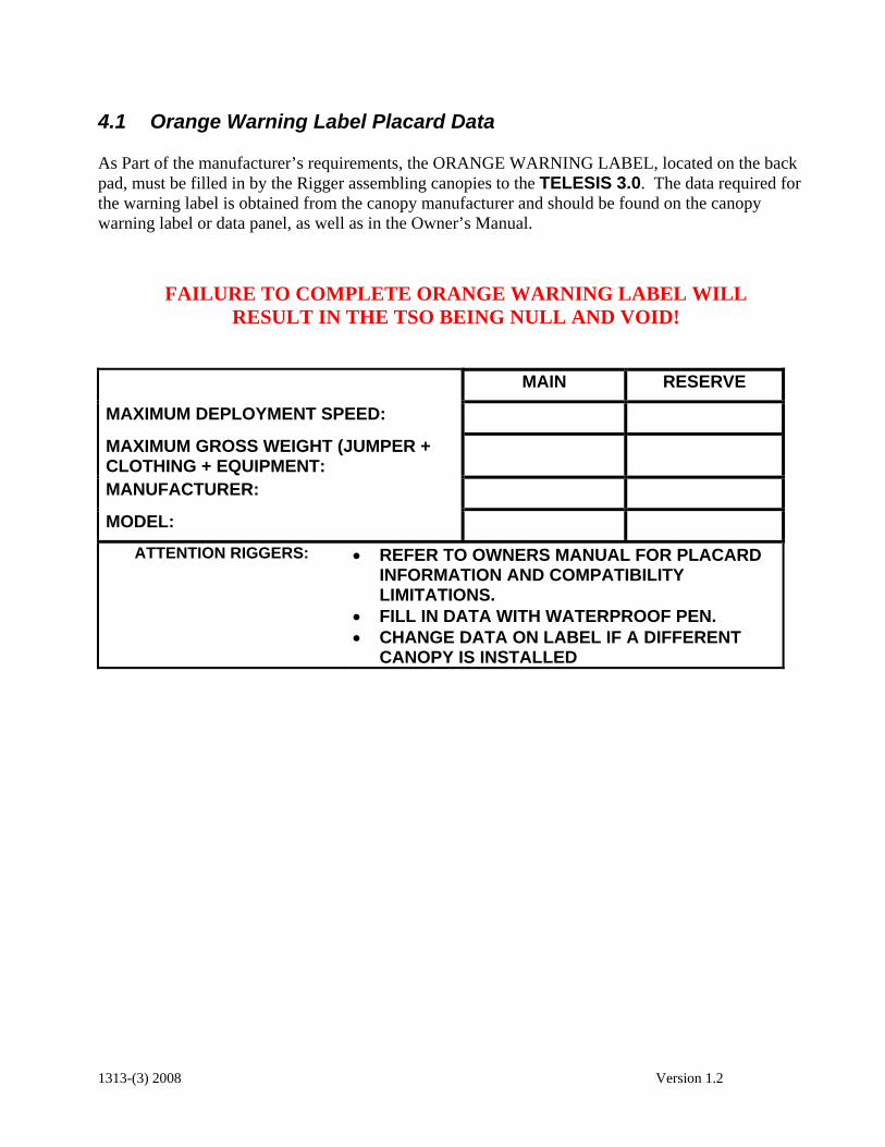
4.1 Orange Warning Label Placard Data As Part of the manufacturer’s requirements, the ORANGE WARNING LABEL, located on the back pad, must be filled in by the Rigger assembling canopies to the TELESIS 3.0. The data required for the warning label is obtained from the canopy manufacturer and should be found on the canopy warning label or data panel, as well as in the Owner’s Manual.
FAILURE TO COMPLETE ORANGE WARNING LABEL WILL RESULT IN THE TSO BEING NULL AND VOID!
MAIN RESERVE
MAXIMUM DEPLOYMENT SPEED:
MAXIMUM GROSS WEIGHT (JUMPER + CLOTHING + EQUIPMENT:
MANUFACTURER:
MODEL:
ATTENTION RIGGERS: • REFER TO OWNERS MANUAL FOR PLACARD INFORMATION AND COMPATIBILITY LIMITATIONS.
• FILL IN DATA WITH WATERPROOF PEN. • CHANGE DATA ON LABEL IF A DIFFERENT
CANOPY IS INSTALLED
1313-(3) 2008 Version 1.2

Parachute Assembly Inspection Form Parachute Assembly Inspection Form
! Note: Count all Tools Before Starting Assembly Qty: Manufacturer:
Model:
Harness and Date of manufacture:
Container Serial no:
Initial After Each Item If No Discrepancies Are Found Initials
1. Main lift web 2. Chest and leg straps 3. Harness hardware and Flex-rings4. 3-ring release 5. Pilotchute pocket 6. Reserve ripcord, handle pocket, cable housing7. Cutaway handle, attachment point, cable housing and channels8. Container flaps and grommets 9. Closing loop length and condition (main and reserve)10. Comments:
Manufacturer:
Model:
Main Canopy and Date of manufacture:
Pilotchute Serial no.: Initial After Each Item If No Discrepancies Are Found Initials
1. Risers and 3-Ring 2. Connector links and slider bumpers3. Slider grommets, tapes, fabric 4. A-lines and attachment points 5. B-lines and attachment points 6. C-lines and attachment points 7. D-lines and attachment points 8. Steering lines and toggles 9. Canopy cells and cross-ports 10. Slider stops ( on canopy ) 11. Bridle line, d-bag stop, pin 12. Pilotchute and handle 13. Deployment bag14. Comments:
A
B
1313-(3) 2008 Version 1.2

Manufacturer:
Model:
Square Reserve Canopy Date of manufacture:
and Pilotchute Serial no:
Initial After Each Item If No Discrepancies Are Found Initials 1. Risers 2. Connector links 3. Sliders & Grommets 4. A-lines and attachment points 5. B-lines and attachment points 6. C-lines and attachment points 7. D-lines and attachment points 8. Steering lines and toggles 9. Canopy cells and cross ports 10. Slider stops (on canopy) 11. Deployment bag and safety stow12.. Bridle line 13. Pilotchute 14. Packing card and information 15. Comments:
Assembly of Square Reserve Canopy
Initial After Each Item If No Discrepancies Are Found Initials 1. Inspection of canopy and Container completed (parts A & C )2. Line Continuity correct including steering lines thru slider grommets3. Slider on correctly 4. Rapide™ links tightened or Slinks™ assembled correctly.5. Steering lines tied to toggles on mark6. Steering line length equal to each other7. Safety stow on deployment bag installed8. Packing data card filled out 9. Packed according to manufacturers instructions10. Reserve pin sealed 11. Fill out warning label 12.
Comments:
C
D
1313-(3) 2008 Version 1.2

Assembly of Main Canopy to Container Initial After Each Item If No Discrepancies Are Found Initials
1. Inspection of canopy and Container completed (parts A & B )2. Line continuity correct including steering lines thru slider grommets.3. Slider on correctly 4. Release handle cables are proper lengths5. Rapide™ links tightened or Slinks™ assembled correctly6. Steering lines tied to toggles on mark7. Steering line length equal to each other8. D-bag, bridle and pilotchute are attached properly9. Fill out warning label 10. Comments:
! Note: Count all tools after assembly and packing is completed to ensure that none were left in the canopy or container.
Qty:
Signature of Rigger(s) Inspection
Signature:
Date:
Print Name and Seal Symbol: Signature:
Date:
Print name and Seal Symbol: General Comments:
E
1313-(3) 2008 Version 1.2
4.3 Ram-Air Reserve Packing Instructions Prior to assembling and packing a square reserve into a TELESIS 3.0, the rigger must thoroughly read and understand these instructions. The rigger must determine reserve and container compatibility based upon volume, deployment type and placard information. Only reserve canopies that have been assigned weight and speed limits by the canopy manufacturer are approved for use in the TELESIS 3.0. The rigger who assembles the reserve is responsible for completing the Orange Warning Label. Refer to the Rigging Innovations Warning Label Placard Data Sheet for proper information. NOTE: Minimum qualification; FAA Senior or Master Parachute Rigger with a BACK rating or foreign equivalent. 4.3.1 Assembling The Reserve System The canopy/rig combination shown in the following photographs is a TS4 size TELESIS 3.0
with a PR-253 reserve canopy. Step 1. Assemble an appropriate size reserve parachute to the TELESIS 3.0 harness and container system ensuring the following:
1.2 Line continuity is correct. 1.3 Connector link bumpers installed and tied per canopy manufacturer’s instructions. 1.4 Connector links are tightened finger tight plus one quarter turn of the barrel. WARNING:
If Maillon rapide links are too tight, barrels will crack. 1.5 Mark connector links with a fine line from a permanent Marker. 1.6 Steering lines are routed through rear grommets on slider. 1.7 Steering lines are routed through guide rings on rear risers. 1.8 Steering toggles are securely attached. 1.9 Automatic Activation Device correctly installed. 1.10 Closing loop length is checked. (See Table IV for approximate length). 1.11 Completely inspect the canopy.
NOTE: Rigging Innovations has tested and evaluated the Slink™ brand of Soft Link manufactured by Performance Designs Inc. RI HIGHLY RECOMMENDS the use of this product in conjunction with the TELESIS 3.0 harness and container system. The use of this product results in a stronger assembly that is easier to pack and more comfortable to the wearer as it eliminates the metal links and the corresponding slider bumper bulk. 4.3.2 Table IV -Approximate Closing Loop Lengths
NOTE: The loop length recommended in this chart is an approximation based on packing experience in our facility. Variables such as canopy size, temperature, humidity, and packing
1313-(3) 2008 Version 1.2
technique will affect the best loop length. In addition, these lengths include the additional length necessary for the AAD cutter.
IT IS THE RIGGER’S RESPONSIBILITY TO ENSURE THE RIPCORD PULL
FORCE DOES NOT EXCEED 22 Lb. (10 Kg.). The loop length is measured from the washer to end of the loop.
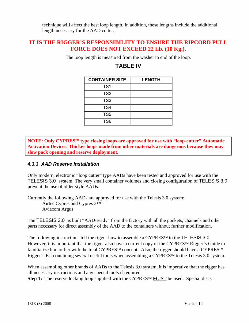
TABLE IV
CONTAINER SIZE LENGTH TS1 TS2 TS3 TS4 TS5 TS6
NOTE: Only CYPRES™ type closing loops are approved for use with “loop-cutter” Automatic Activation Devices. Thicker loops made from other materials are dangerous because they may slow pack opening and reserve deployment. 4.3.3 AAD Reserve Installation Only modern, electronic “loop cutter” type AADs have been tested and approved for use with the TELESIS 3.0 system. The very small container volumes and closing configuration of TELESIS 3.0 prevent the use of older style AADs. Currently the following AADs are approved for use with the Telesis 3.0 system: Airtec Cypres and Cypres 2™ Aviacom Argus The TELESIS 3.0 is built “AAD-ready” from the factory with all the pockets, channels and other parts necessary for direct assembly of the AAD to the containers without further modification. The following instructions tell the rigger how to assemble a CYPRES™ to the TELESIS 3.0. However, it is important that the rigger also have a current copy of the CYPRES™ Rigger’s Guide to familiarize him or her with the total CYPRES™ concept. Also, the rigger should have a CYPRES™ Rigger’s Kit containing several useful tools when assembling a CYPRES™ to the Telesis 3.0 system. When assembling other brands of AADs to the Telesis 3.0 system, it is imperative that the rigger has all necessary instructions and any special tools if required. Step 1: The reserve locking loop supplied with the CYPRES™ MUST be used. Special discs
1313-(3) 2008 Version 1.2

supplied with CYPRES™ must also be used to make knots for locking loop. Step 2: Adjust locking loop to appropriate length in accordance with Table IV. Install locking loop into container. Step 3: Install CYPRES™ processing unit into spandex pocket on divider wall at bottom of reserve container. (Fig 4-1)
Fig 4-1
Step 4: Thread the cutter unit up through grommet and then through the spandex channel on inside of right reserve side flap. Push the cutter through the elastic keeper next to the grommet and align hole in cutter with grommet. (Fig 4-2)
Fig 4-2
Step 5: Carefully coil excess cutter cable under Velcro closure flap located on right end of CYPRES™ installation pocket. DO NOT bend or kink excess cable. (Fig 4-3)
Fig 4-3
Step 6: Carefully push control unit through channel on bottom of reserve container from bottom to top. (Fig 4-4)
Fig 4-4
1313-(3) 2008 Version 1.2
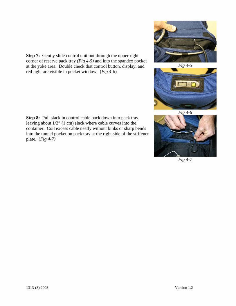
Fig 4-5
Step 7: Gently slide control unit out through the upper right corner of reserve pack tray (Fig 4-5) and into the spandex pocket at the yoke area. Double check that control button, display, and red light are visible in pocket window. (Fig 4-6)
Fig 4-6
Step 8: Pull slack in control cable back down into pack tray, leaving about 1/2” (1 cm) slack where cable curves into the container. Coil excess cable neatly without kinks or sharp bends into the tunnel pocket on pack tray at the right side of the stiffener plate. (Fig 4-7)
Fig 4-7
1313-(3) 2008 Version 1.2
4.3.4 Folding the Reserve Parachute Before you start! Check for recent updates or R.I. Service Bulletins
Telephone: (520) 466.2655
FAX: (520) 466.2656
Website: www.rigginginnovations.com Note: Pro packing of Ram-Air reserves has progressed significantly in recent years. Experience has shown that there are several distinctive techniques currently being used with great success and no discernable problems identified. If the intent of the procedure is followed, and the resultant configuration of the canopy is compatible with the shape and configuration of the reserve deployment bag, the actual technique used to accomplish it may be flexible, as long as it does not contradict any specific requirements from the canopy manufacturer. Rigging Innovations mandates PRO (Proper Ram-air Orientation) packing for packing ram-air reserves into TELESIS 3.0 reserve containers. PRO packing results in the best bulk distribution and greatest comfort for the wearer. The molar method is used to insert the parachute into the deployment bag. Since 1985 and the first generation Talon, Rigging Innovations has tested and sanctioned 3 different packing methods for packing ram-air reserves into their container systems. The following procedure is one method that Rigging Innovations currently uses. The process of shaping the canopy stack and the molar ears is very much subject to individual technique. The shape of the TELESIS 3.0 reserve container and bag is more rounded at the top as opposed to other more tapered designs such as the Talon 2. This is in keeping with the aerodynamic convex curve of the TELESIS 3.0 profile. The ears of the molar bag are designed to accept more bulk to create the “TELESIS 3.0” curve.
1313-(3) 2008 Version 1.2
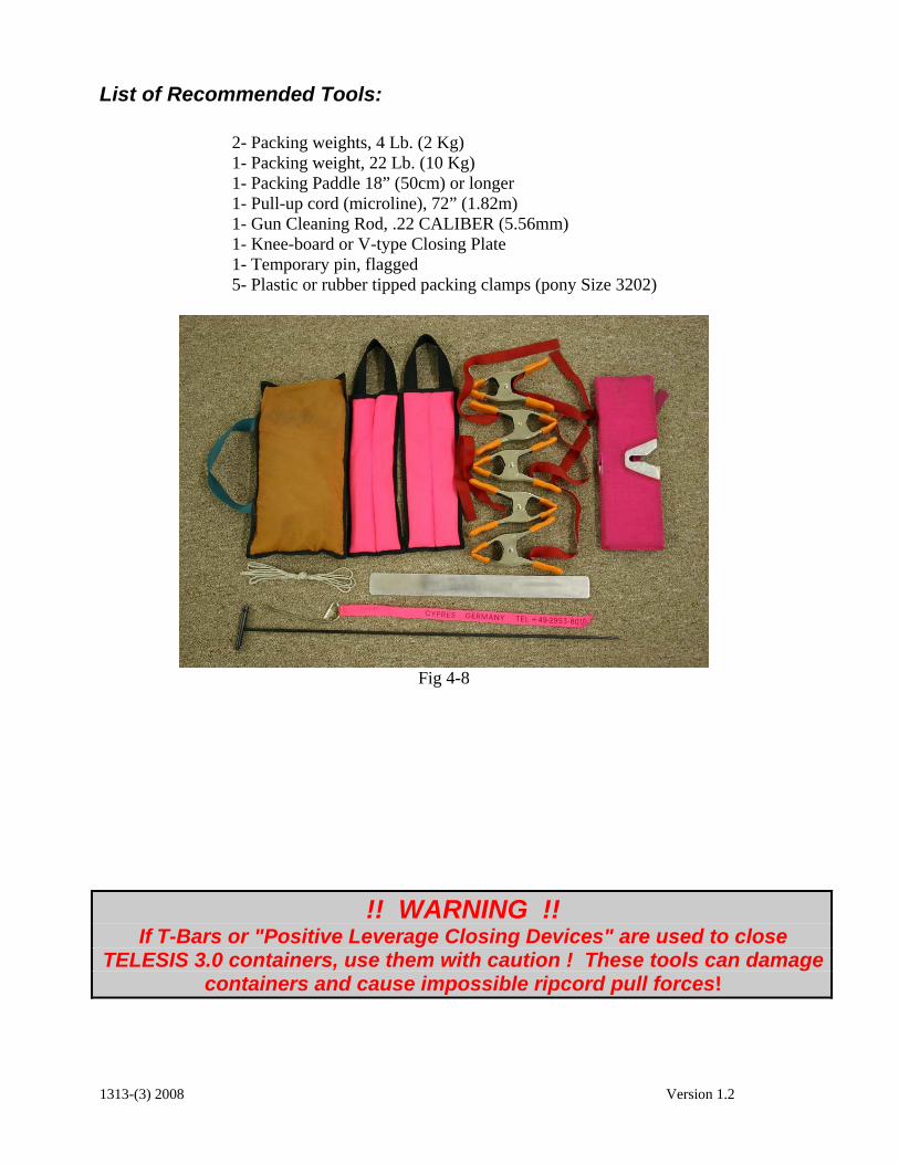
List of Recommended Tools:
2- Packing weights, 4 Lb. (2 Kg) 1- Packing weight, 22 Lb. (10 Kg) 1- Packing Paddle 18” (50cm) or longer 1- Pull-up cord (microline), 72” (1.82m) 1- Gun Cleaning Rod, .22 CALIBER (5.56mm) 1- Knee-board or V-type Closing Plate 1- Temporary pin, flagged 5- Plastic or rubber tipped packing clamps (pony Size 3202)
Fig 4-8
!! WARNING !! If T-Bars or "Positive Leverage Closing Devices" are used to close
TELESIS 3.0 containers, use them with caution ! These tools can damage containers and cause impossible ripcord pull forces!
1313-(3) 2008 Version 1.2

Reserve Parachute Pro Packing Instructions 1-Basic layout and setting up packing clamps Anchor the risers at the connector links including the steering lines. (Fig.4-9) Place packing weight on top of it.
Fig 4-9
Pull the slider down to the connector links. Make sure the tapes face upwards towards the canopy. (Fig 4-10)
Fig 4-10
Lay the canopy on its right side. (Note: A mirror image of the layout is permissible). Flake the canopy so that the top seams are even. Place a clamp on the top of the canopy in line with each line attachment point as in the photo. (Fig 4-11)
Fig 4-11
1313-(3) 2008 Version 1.2
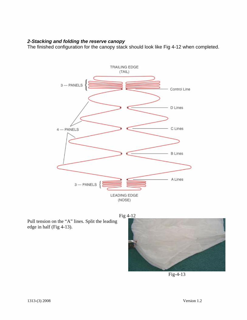
2-Stacking and folding the reserve canopy The finished configuration for the canopy stack should look like Fig 4-12 when completed.
Fig 4-12
Pull tension on the “A” lines. Split the leading edge in half (Fig 4-13).
Fig-4-13
1313-(3) 2008 Version 1.2

Fig 4-14
Fold half under ”A”-lines (Figs 4-14 and 4-15)
Fig 4-15
Pick up the “B” lines by the clamp and hold vertically over the “A” clamp (Fig 4-16) Note the spread of the leading edge panels.
Fig 4-16
1313-(3) 2008 Version 1.2

Next stack the “B” lines on top of the “A” lines while distributing the cells equally to both sides. (Fig 4-17) Keep the center cell in the middle.
Fig 4-17
Fig 4-18
Repeat this step with the “C” (Fig 4-18) and “D” line groups (Fig 4-19)
Fig 4-19
1313-(3) 2008 Version 1.2
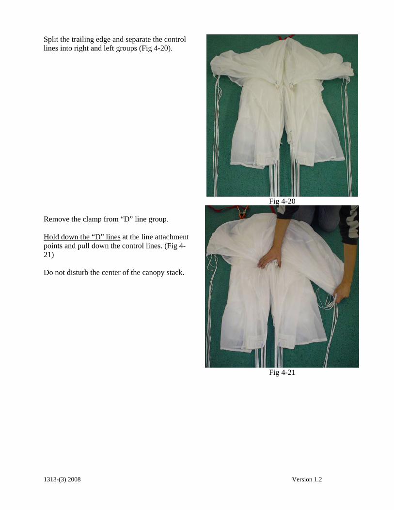
Split the trailing edge and separate the control lines into right and left groups (Fig 4-20).
Fig 4-20
Remove the clamp from “D” line group. Hold down the “D” lines at the line attachment points and pull down the control lines. (Fig 4-21) Do not disturb the center of the canopy stack.
Fig 4-21
1313-(3) 2008 Version 1.2

Set the deployment brakes and stow the excess line in the Velcro keepers. (Fig. 4-22). The finished toggles should look like Fig. 4-23
Fig 4-22
Fig 4-23
Fold all the trailing edge to one side then pull the stabilizer panel taut (Fig 4-24).
Fig 4-24
1313-(3) 2008 Version 1.2
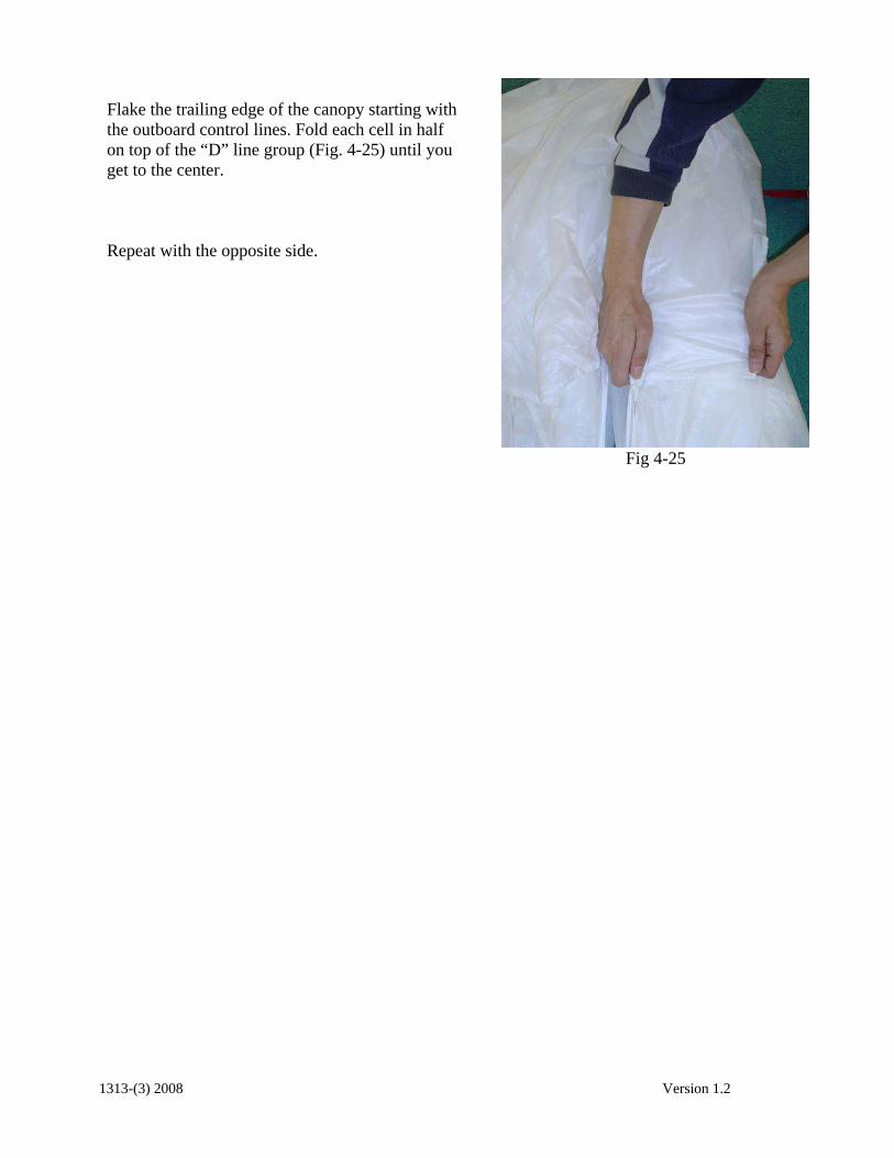
Flake the trailing edge of the canopy starting with the outboard control lines. Fold each cell in half on top of the “D” line group (Fig. 4-25) until you get to the center. Repeat with the opposite side.
Fig 4-25
1313-(3) 2008 Version 1.2

3- Place canopy into the deployment bag and stowing the lines Make sure all suspension lines are taut and towards the center of the pack job. (Fig 4-26)
Fig 4-26
Pull slider up to the slider stops. Fold the center of the trailing edge back to expose the center of the “wind channel”. (Fig. 4-27)
Fig 4-27
1313-(3) 2008 Version 1.2
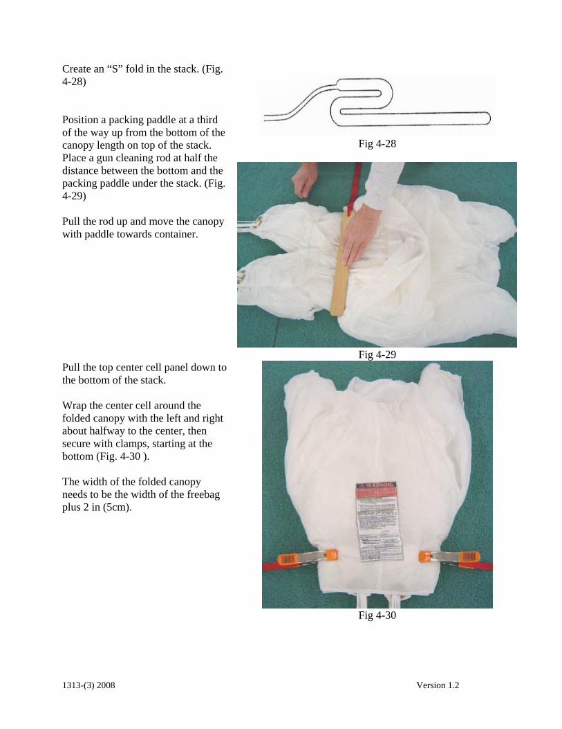
Create an “S” fold in the stack. (Fig. 4-28) Position a packing paddle at a third of the way up from the bottom of the canopy length on top of the stack. Place a gun cleaning rod at half the distance between the bottom and the packing paddle under the stack. (Fig. 4-29) Pull the rod up and move the canopy with paddle towards container.
Fig 4-28
Fig 4-29
Pull the top center cell panel down to the bottom of the stack. Wrap the center cell around the folded canopy with the left and right about halfway to the center, then secure with clamps, starting at the bottom (Fig. 4-30 ). The width of the folded canopy needs to be the width of the freebag plus 2 in (5cm).
Fig 4-30
1313-(3) 2008 Version 1.2
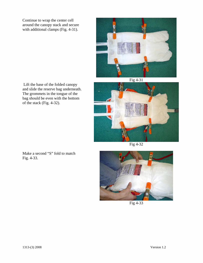
Continue to wrap the center cell around the canopy stack and secure with additional clamps (Fig. 4-31).
Fig 4-31
Lift the base of the folded canopy and slide the reserve bag underneath. The grommets in the tongue of the bag should be even with the bottom of the stack (Fig. 4-32).
Fig 4-32
Make a second “S” fold to match Fig. 4-33.
Fig 4-33
1313-(3) 2008 Version 1.2

Fig 4-34A
Fig 4-34
Split the loose fabric at the top to form two “ears” (Fig 4-35).
Fig 4-35
Gather the center cell material along the middle seam until you reach the bottom along the middle seam. (Fig. 4-36)
Fig 4-36
1313-(3) 2008 Version 1.2
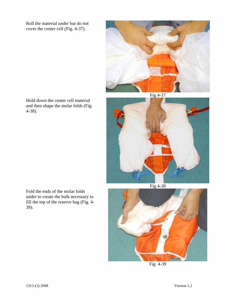
Roll the material under but do not cover the center cell (Fig. 4-37).
Fig 4-37
Hold down the center cell material and then shape the molar folds (Fig. 4-38).
Fig 4-38
Fold the ends of the molar folds under to create the bulk necessary to fill the top of the reserve bag (Fig. 4-39).
Fig 4-39
1313-(3) 2008 Version 1.2
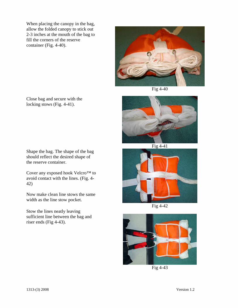
When placing the canopy in the bag, allow the folded canopy to stick out 2-3 inches at the mouth of the bag to fill the corners of the reserve container (Fig. 4-40).
Fig 4-40
Close bag and secure with the locking stows (Fig. 4-41).
Fig 4-41
Shape the bag. The shape of the bag should reflect the desired shape of the reserve container. Cover any exposed hook Velcro™ to avoid contact with the lines. (Fig. 4-42) Now make clean line stows the same width as the line stow pocket.
Fig 4-42
Stow the lines neatly leaving sufficient line between the bag and riser ends (Fig 4-43).
Fig 4-43
1313-(3) 2008 Version 1.2
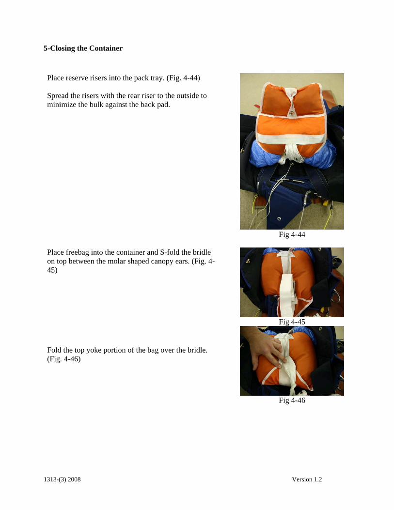
5-Closing the Container
Place reserve risers into the pack tray. (Fig. 4-44) Spread the risers with the rear riser to the outside to minimize the bulk against the back pad.
Fig 4-44
Place freebag into the container and S-fold the bridle on top between the molar shaped canopy ears. (Fig. 4-45) Fold the top yoke portion of the bag over the bridle. (Fig. 4-46)
Fig 4-45
Fig 4-46
1313-(3) 2008 Version 1.2

Secure in place with a clamp. (Fig. 4-47)
Fig 4-47
Use the gun cleaning rod to thread the pull-up cord through Stealth pilotchute from bottom to top. (Fig. 4-48).
Fig 4-48
Center the base of the pilot chute on center grommet of freebag. Compress pilot chute while stuffing fabric and mesh between the spring coils. Position the cap of the pilot chute with the arrow facing toward top or bottom of container. (Fig. 4-49). Secure with temporary pin.
Fig 4-49
WARNING! Do not leave fabric outside of spring coils as a coil lock could occur and pilotchute launch may be inhibited!
If an AAD such as a Cypres™ is installed, route the pull-up cord through the cutter first then through the right (#1)side flap grommet. (Fig. 4-50)
Fig 4-50
1313-(3) 2008 Version 1.2
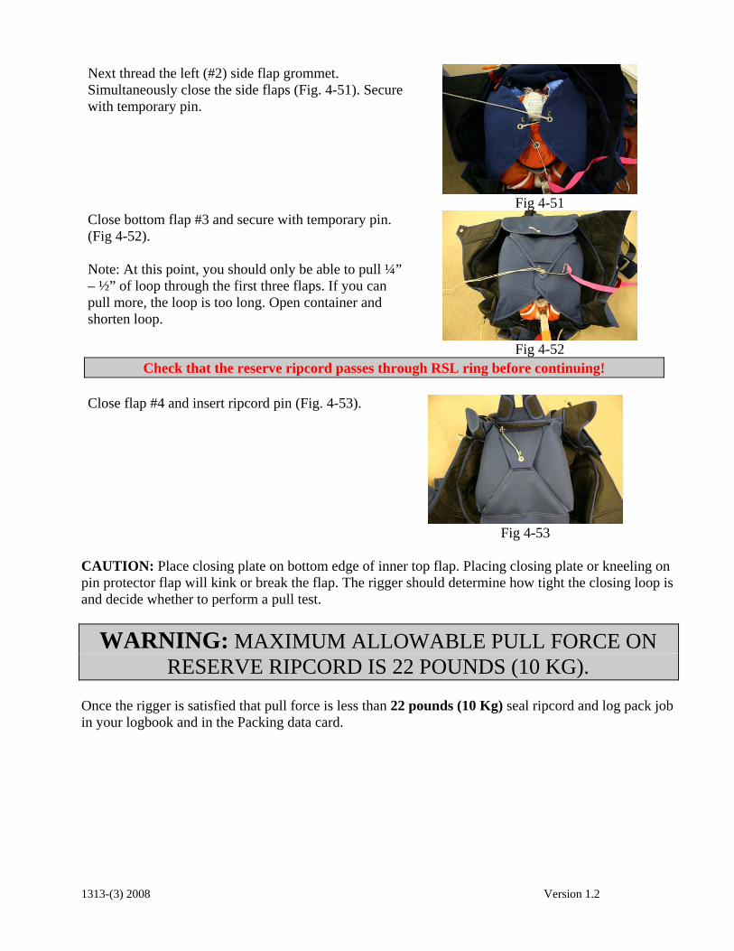
Next thread the left (#2) side flap grommet. Simultaneously close the side flaps (Fig. 4-51). Secure with temporary pin.
Fig 4-51
Close bottom flap #3 and secure with temporary pin. (Fig 4-52). Note: At this point, you should only be able to pull ¼” – ½” of loop through the first three flaps. If you can pull more, the loop is too long. Open container and shorten loop.
Fig 4-52
Check that the reserve ripcord passes through RSL ring before continuing!
Close flap #4 and insert ripcord pin (Fig. 4-53).
Fig 4-53
CAUTION: Place closing plate on bottom edge of inner top flap. Placing closing plate or kneeling on pin protector flap will kink or break the flap. The rigger should determine how tight the closing loop is and decide whether to perform a pull test.
WARNING: MAXIMUM ALLOWABLE PULL FORCE ON RESERVE RIPCORD IS 22 POUNDS (10 KG).
Once the rigger is satisfied that pull force is less than 22 pounds (10 Kg) seal ripcord and log pack job in your logbook and in the Packing data card.
1313-(3) 2008 Version 1.2

Place the data card in the data card pocket (Fig 4-54).
Fig 4-54
COUNT YOUR TOOLS!
COMPLETE PLACARD DATA ON ORANGE WARNING LABEL.
FAILURE TO COMPLETE ORANGE WARNING LABEL WILL
VOID THE TSO.
1313-(3) 2008 Version 1.2