section 4. factory-made wrought steel buttwelding...
TRANSCRIPT

Section 4. Factory-Made Wrought Steel Buttwelding Fittings
ASME B16.9 Buttwelding Fittings are designed and manufactured in accordance with the following specifications:-
ASME B16.9 Factory-Made Wrought Steel Buttwelding Fittings.
MSS-SP-43 Wrought Stainless Steel Butt Weld Fittings.
MSS-SP-75 Specification for High Test Wrought Butt Weld Fittings.
ANSI B31.3 Chemical Plant and Petroleum Refinery Piping.
ASME VIII Boiler and Pressure Vessel Code.
API 6A Specification for Wellhead and Christmas Tree Equipment.
NACE MR-01-75 Sulphide Stress Cracking Resistant Metallic Materials for Oilfield Equipment.
Buttwelding Fittings are available in either equal or with reducing configuration to suit various pressure ratings using materials as shown in the table below
(for full material details please refer to Section 1):-
PRoPERTY A234 A420 A182 A860 A182 F51 AISI 4130
Gr WPB Gr WPL6 Gr 316L Gr WPHY52 UNS 31803
TENSILE 60,000 PSI 60,000 PSI 70,000 PSI 66,000 PSI 90,000 PSI 105,000 PSI
STRENGTH 415 MPa 415 MPa 485 MPa 455 MPa 620 MPa 725 MPa
YIELD 35,000 PSI 35,000 PSI 25,000 PSI 52,000 PSI 65,000 PSI >80,000 PSI
STRENGTH 240 MPa 240 MPa 170 MPa 360 MPa 450 MPa >551 MPa
IMPACT VALUES N/A 18J min.av. N/A 27J min.av. 27J min.av. 42J min.av.
DEG C -45˚C -50˚C -50˚C -50˚C
HARDNESS 197 HB N/A N/A 235 HB 237HB 237HB
(MAX.)
ELONGATION Long. 30% Long. 30% 30% 32% 25% 18%
In 2“ or 50mm Trans. 20% Trans. 16.5%
GENERAL NOTE: Please contact GonPetro for any special material or dimensional requirements.

Section 4. Factory-Made Wrought Steel Buttwelding Fittings
Table 4.1 Dimensions of Long Radius Elbows
Nominal
Pipe
Size
(NPS)
Outside Diameter at Bevel
D
90 deg. Elbows
A
Centre-to-End
45 deg. Elbows
B
Min. Nom. Max. Min. Nom. Max. Min. Nom. Max.
1⁄ 2 20 21 22 36 38 40 14 16 18
3⁄ 4 26 27 28 36 38 40 17 19 21
1 32 33 34 36 38 40 20 22 24
1 1⁄ 4 41 42 43 46 48 50 23 25 27
1 1⁄ 2 47 48 49 55 57 59 27 29 31
2 59 60 61 74 76 78 33 35 37
2 1⁄ 2 72 73 74 93 95 97 42 44 46
3 88 89 90 112 114 116 49 51 53
3 1⁄ 2 101 102 103 131 133 135 55 57 59
4 113 114 116 150 152 154 62 64 66
5 140 141 144 188 190 192 77 79 81
6 167 168 171 227 229 231 93 95 97
8 217 219 221 303 305 307 125 127 129
10 270 273 277 379 381 383 157 159 161
GENERAL NOTE: Dimensions are in mm.

Table 4.1 Dimensions of Long Radius Elbows
Nominal
Pipe
Size
(NPS)
Outside Diameter at Bevel
D
90 deg. Elbows
A
Centre-to-End
45 deg. Elbows
B
Min. Nom. Max. Min. Nom. Max. Min. Nom. Max.
12 321 324 328 454 457 460 187 190 193
14 353 356 360 530 533 536 219 222 225
16 403 406 410 607 610 613 251 254 257
18 454 457 461 683 686 689 283 286 289
20 503 508 514 759 762 765 315 318 321
22 554 559 565 835 838 841 340 343 346
24 605 610 616 911 914 917 378 381 384
26 655 660 667 988 991 994 403 406 409
28 706 711 718 1064 1067 1070 435 438 441
30 757 762 769 1140 1143 1146 467 470 473
32 808 813 820 1214 1219 1224 497 502 507
34 859 864 871 1290 1295 1300 528 533 538
36 909 914 921 1367 1372 1377 560 565 570
38 960 965 972 1443 1448 1453 595 600 605
40 1011 1016 1023 1519 1524 1529 627 632 637
42 1062 1067 1074 1595 1600 1605 655 660 665
44 1113 1118 1125 1671 1676 1681 690 695 700
46 1163 1168 1175 1748 1753 1758 722 727 732
48 1214 1219 1226 1824 1829 1834 754 759 764
GENERAL NOTE: Dimensions are in mm.

Section 4. Factory-Made Wrought Steel Buttwelding Fittings
Table 4.2 Dimensions of Long Radius Returns
1⁄ 2 20 21 22 69 76 83 41 48 55
3⁄ 4 26 27 28 69 76 83 44 51 58
1 32 33 34 69 76 83 49 56 63
1 1⁄ 4 41 42 43 88 95 102 63 70 77
1 1⁄ 2 47 48 49 107 114 121 76 83 90
2 59 60 61 145 152 159 99 106 113
2 1⁄ 2 72 73 74 184 191 198 125 132 139
3 88 89 90 222 229 236 152 159 166
3 1⁄ 2 101 102 103 260 267 274 177 184 191
4 113 114 116 298 305 312 203 210 217
5 140 141 144 374 381 388 255 262 269
6 167 168 171 450 457 464 306 313 320
8 217 219 221 603 610 617 407 414 421
10 270 273 277 752 762 772 511 518 525
Nominal
Pipe
Size
(NPS)
Outside Diameter at Bevel
D
Centre-to-Centre
A
Back-to-Face
B
Min. Nom. Max. Min. Nom. Max. Min. Nom. Max.
GENERAL NOTE: Dimensions are in mm.

Table 4.2 Dimensions of Long Radius Returns
12 321 324 328 904 914 924 612 619 626
14 353 356 360 1057 1067 1077 704 711 718
16 403 406 410 1209 1219 1229 806 813 820
18 454 457 461 1362 1372 1382 907 914 921
20 503 508 514 1514 1524 1534 1009 1016 1023
22 554 559 565 1666 1676 1686 1111 1118 1125
24 605 610 616 1819 1829 1839 1212 1219 1226
GENERAL NOTES: Dimensions are in mm.
Dimension R is equal to half of dimension A.
Nominal
Pipe
Size
(NPS)
Outside Diameter at Bevel
D
Centre-to-Centre
A
Back-to-Face
B
Min. Nom. Max. Min. Nom. Max. Min. Nom. Max.

Section 4. Factory-Made Wrought Steel Buttwelding Fittings
Table 4.3 Dimensions of Straight Tees and Crosses
1⁄ 2 20 21 22 23 25 27 23 25 27
3⁄ 4 26 27 28 27 29 31 27 29 31
1 32 33 34 36 38 40 36 38 40
1 1⁄ 4 41 42 43 46 48 50 46 48 50
1 1⁄ 2 47 48 49 55 57 59 55 57 59
2 59 60 61 62 64 66 62 64 66
2 1⁄ 2 72 73 74 74 76 78 74 76 78
3 88 89 90 84 86 88 84 86 88
3 1⁄ 2 101 102 103 93 95 97 93 95 97
4 113 114 116 103 105 107 103 105 107
5 140 141 144 122 124 126 122 124 126
6 167 168 171 141 143 145 141 143 145
8 217 219 221 176 178 180 176 178 180
10 270 273 277 214 216 218 214 216 218
Nominal
Pipe
Size
(NPS)
Outside Diameter at Bevel
D Run
A
Centre-to-End
Outlet
B
Min. Nom. Max. Min. Nom. Max. Min. Nom. Max.
GENERAL NOTE: Dimensions are in mm.

Table 4.3 Dimensions of Straight Tees and Crosses
12 321 324 328 251 254 257 251 254 257
14 353 356 360 276 279 282 276 279 282
16 403 406 410 302 305 308 302 305 308
18 454 457 461 340 343 346 340 343 346
20 503 508 514 378 381 384 378 381 384
22 554 559 565 416 419 422 416 419 422
24 605 610 616 429 432 435 429 432 435
26 655 660 667 492 495 498 492 495 498
28 706 711 718 518 521 524 518 521 524
30 757 762 769 556 559 562 556 559 562
32 808 813 820 592 597 602 592 597 602
34 859 864 871 630 635 640 630 635 640
36 909 914 921 668 673 678 668 673 678
38 960 965 972 706 711 716 706 711 716
40 1011 1016 1023 744 749 754 744 749 754
42 1062 1067 1074 757 762 767 706 711 716
44 1113 1118 1125 808 813 818 757 762 767
46 1163 1168 1175 846 851 856 795 800 805
48 1214 1219 1226 884 889 894 833 838 843
GENERAL NOTE: Dimensions are in mm.
Nominal
Pipe
Size
(NPS)
Outside Diameter at Bevel
D Run
A
Centre-to-End
Outlet
B
Min. Nom. Max. Min. Nom. Max. Min. Nom. Max.
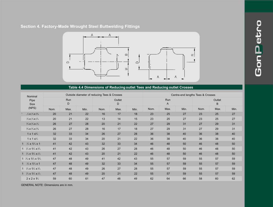
Section 4. Factory-Made Wrought Steel Buttwelding Fittings
Table 4.4 Dimensions of Reducing outlet Tees and Reducing outlet Crosses
1 ⁄ 2 x 1⁄ 2 x 3⁄ 8 20 21 22 16 17 18 23 25 27 23 25 27
1⁄ 2 x 1⁄ 2 x 1⁄ 4 20 21 22 13 14 15 23 25 27 23 25 27
3⁄ 4 x 3⁄ 4 x 1⁄ 2 26 27 28 20 21 22 27 29 31 27 29 31
3⁄ 4 x 3⁄ 4 x 3⁄ 8 26 27 28 16 17 18 27 29 31 27 29 31
1 x 1 x 3⁄ 4 32 33 34 26 27 28 36 38 40 36 38 40
1 x 1 x 1⁄ 2 32 33 34 20 21 22 36 38 40 36 38 40
1 1⁄ 4 x 11⁄ 4 x 1 41 42 43 32 33 34 46 48 50 46 48 50
1 1⁄ 4 x 11⁄ 4 x 3⁄ 4 41 42 43 26 27 28 46 48 50 46 48 50
1 1⁄ 4 x 11⁄ 4 x 1⁄ 2 41 42 43 20 21 22 46 48 50 46 48 50
1 1⁄ 2 x 11⁄ 2 x 11⁄ 4 47 48 49 41 42 43 55 57 59 55 57 59
1 1⁄ 2 x 11⁄ 2 x 1 47 48 49 32 33 34 55 57 59 55 57 59
1 1⁄ 2 x 11⁄ 2 x 3⁄ 4 47 48 49 26 27 28 55 57 59 55 57 59
1 1⁄ 2 x 11⁄ 2 x 1⁄ 2 47 48 49 20 21 22 55 57 59 55 57 59
2 x 2 x 11⁄ 2 59 60 61 47 48 49 62 64 66 58 60 62
Nominal
Pipe
Size
(NPS)
Outside diameter of reducing Tees & Crosses
Run
A
Centre-end lengths Tees & Crosses
Outlet
B
Run
D
Outlet
D
Nom. Max. Min. Nom. Max. Min.Nom. Max. Min.Nom. Max. Min.
GENERAL NOTE: Dimensions are in mm.

Table 4.4 Dimensions of Reducing outlet Tees and Reducing outlet Crosses
2 x 2 x 11⁄ 4 59 60 61 41 42 43 62 64 66 55 57 59
2 x 2 x 1 59 60 61 32 33 34 62 64 66 49 51 53
2 x 2 x 3⁄ 4 59 60 61 26 27 28 62 64 66 42 44 46
2 1⁄ 2 x 21⁄ 2 x 2 72 73 74 59 60 61 74 76 78 68 70 72
2 1⁄ 2 x 21⁄ 2 x 11⁄ 2 72 73 74 47 48 49 74 76 78 65 67 69
2 1⁄ 2 x 21⁄ 2 x 11⁄ 4 72 73 74 41 42 43 74 76 78 62 64 66
2 1⁄ 2 x 21⁄ 2 x 1 72 73 74 32 33 34 74 76 78 55 57 59
3 x 3 x 21⁄ 2 88 89 90 72 73 74 84 86 88 81 83 85
3 x 3 x 2 88 89 90 59 60 61 84 86 88 74 76 78
3 x 3 x 11⁄ 2 88 89 90 47 48 49 84 86 88 71 73 75
3 x 3 x 11⁄ 4 88 89 90 41 42 43 84 86 88 68 70 72
3 1⁄ 2 x 31⁄ 2 x 3 101 102 103 88 89 90 93 95 97 90 92 94
3 1⁄ 2 x 31⁄ 2 x 21⁄ 2 101 102 103 72 73 74 93 95 97 87 89 91
3 1⁄ 2 x 31⁄ 2 x 2 101 102 103 59 60 61 93 95 97 81 83 85
3 1⁄ 2 x 31⁄ 2 x 11⁄ 2 101 102 103 47 48 49 93 95 97 77 79 81
4 x 4 x 31⁄ 2 113 114 116 101 102 103 103 105 107 100 102 104
4 x 4 x 3 113 114 116 88 89 90 103 105 107 96 98 100
4 x 4 x 21⁄ 2 113 113 116 72 73 74 103 105 107 93 95 97
4 x 4 x 2 113 114 116 59 60 61 103 105 107 87 89 91
4 x 4 x 11⁄ 2 113 114 116 47 48 49 103 105 107 84 86 88
5 x 5 x 4 140 141 144 113 114 116 122 124 126 115 117 119
Nominal
Pipe
Size
(NPS)
Outside diameter of reducing Tees & Crosses
Run
A
Centre-end lengths Tees & Crosses
Outlet
B
Run
D
Outlet
D
Nom. Max. Min. Nom. Max. Min.Nom. Max. Min.Nom. Max. Min.
GENERAL NOTE: Dimensions are in mm.

Section 4. Factory-Made Wrought Steel Buttwelding Fittings
5 x 5 x 31⁄ 2 140 141 144 101 102 103 122 124 126 112 114 116
5 x 5 x 3 140 141 144 88 89 90 122 124 126 109 111 113
5 x 5 x 21⁄ 2 140 141 144 72 73 74 122 124 126 106 108 110
5 x 5 x 2 140 141 144 59 60 61 122 124 126 103 105 107
6 x 6 x 5 167 168 171 140 141 144 141 143 145 135 137 139
6 x 6 x 4 167 168 171 113 114 116 141 143 145 128 130 132
6 x 6 x 31⁄ 2 167 168 171 101 102 103 141 143 145 125 127 129
6 x 6 x 3 167 168 171 88 89 90 141 143 145 122 124 126
6 x 6 x 21⁄ 2 167 168 171 72 73 74 141 143 145 119 121 123
8 x 8 x 6 217 219 221 167 168 171 176 178 180 166 168 170
8 x 8 x 5 217 219 221 140 141 144 176 178 180 160 162 164
8 x 8 x 4 217 219 221 113 114 116 176 178 180 154 156 158
8 x 8 x 31⁄ 2 217 219 221 101 102 103 176 178 180 150 152 154
10 x 10 x 8 270 273 277 217 219 221 214 216 218 201 203 205
Table 4.4 Dimensions of Reducing outlet Tees and Reducing outlet Crosses
Nominal
Pipe
Size
(NPS)
Outside diameter of reducing Tees & Crosses
Run
A
Centre-end lengths Tees & Crosses
Outlet
B
Run
D
Outlet
D
Nom. Max. Min. Nom. Max. Min.Nom. Max. Min.Nom. Max. Min.
GENERAL NOTE: Dimensions are in mm.

10 x 10 x 6 270 273 277 167 168 171 214 216 218 192 194 196
10 x 10 x 5 270 273 277 140 141 144 214 216 218 189 191 193
10 x 10 x 4 270 273 277 113 114 116 214 216 218 182 184 186
12 x 12 x 10 321 324 328 270 273 277 251 254 257 238 241 244
12 x 12 x 8 321 324 328 217 219 221 251 254 257 226 229 232
12 x 12 x 6 321 324 328 167 168 171 251 254 257 216 219 222
12 x 12 x 5 321 324 328 140 140 144 251 254 257 213 216 219
14 x 14 x 12 353 356 360 321 324 328 276 279 282 267 270 273
14 x 14 x 10 353 356 360 270 273 277 276 279 282 254 257 260
14 x 14 x 8 353 356 360 217 219 221 276 279 282 245 248 251
14 x 14 x 6 353 356 360 167 168 171 276 279 282 235 238 241
16 x 16 x 14 403 406 410 353 356 360 302 305 308 302 305 308
16 x 16 x 12 403 406 410 321 324 328 302 305 308 292 295 298
16 x 16 x 10 403 406 410 270 273 277 302 305 308 280 283 286
16 x 16 x 8 403 406 410 217 219 221 302 305 308 270 273 276
16 x 16 x 6 403 406 410 167 168 171 302 305 308 261 264 267
18 x 18 x 16 454 457 461 403 406 410 340 343 346 327 330 333
18 x 18 x 14 454 457 461 353 356 360 340 343 346 327 330 333
18 x 18 x 12 454 457 461 321 324 328 340 343 346 318 321 324
18 x 18 x 10 454 457 461 270 273 277 340 343 346 305 308 311
18 x 18 x 8 454 457 461 217 219 221 340 343 346 295 298 301
Table 4.4 Dimensions of Reducing outlet Tees and Reducing outlet Crosses
Nominal
Pipe
Size
(NPS)
Outside diameter of reducing Tees & Crosses
Run
A
Centre-end lengths Tees & Crosses
Outlet
B
Run
D
Outlet
D
Nom. Max. Min. Nom. Max. Min.Nom. Max. Min.Nom. Max. Min.
GENERAL NOTE: Dimensions are in mm.

Section 4. Factory-Made Wrought Steel Buttwelding Fittings
20 x 20 x 18 503 508 514 454 457 461 378 381 384 365 368 371
20 x 20 x 16 503 508 514 403 406 410 378 381 384 353 356 359
20 x 20 x 14 503 508 514 353 356 360 378 381 384 353 356 359
20 x 20 x 12 503 508 514 321 324 328 378 381 384 343 346 349
20 x 20 x 10 503 508 514 270 273 277 378 381 384 330 333 336
20 x 20 x 8 503 508 514 217 219 221 378 381 384 321 324 327
22 x 22 x 20 554 559 565 503 508 514 416 419 422 403 406 409
22 x 22 x 18 554 559 565 454 457 461 416 419 422 391 394 397
22 x 22 x 16 554 559 565 403 406 410 416 419 422 378 381 384
22 x 22 x 14 554 559 565 353 356 360 416 419 422 378 381 384
22 x 22 x 12 554 559 565 321 324 328 416 419 422 368 371 374
22 x 22 x 10 554 559 565 270 273 277 416 419 422 356 359 362
24 x 24 x 22 605 610 616 554 559 565 429 432 435 429 432 435
24 x 24 x 20 605 610 616 503 508 514 429 432 435 429 432 435
Table 4.4 Dimensions of Reducing outlet Tees and Reducing outlet Crosses
Nominal
Pipe
Size
(NPS)
Outside diameter of reducing Tees & Crosses
Run
A
Centre-end lengths Tees & Crosses
Outlet
B
Run
D
Outlet
D
Nom. Max. Min. Nom. Max. Min.Nom. Max. Min.Nom. Max. Min.
GENERAL NOTE: Dimensions are in mm.

24 x 24 x 18 605 610 616 454 457 461 429 432 435 416 419 422
24 x 24 x 16 605 610 616 403 406 410 429 432 435 403 406 409
24 x 24 x 14 605 610 616 353 356 360 429 432 435 403 406 409
24 x 24 x 12 605 610 616 321 324 328 429 432 435 394 397 400
24 x 24 x 10 605 610 616 270 273 277 429 432 435 381 384 387
26 x 26 x 24 655 660 667 605 610 616 492 495 498 480 483 486
26 x 26 x 22 655 660 667 554 559 565 492 495 498 467 470 473
26 x 26 x 20 655 660 667 503 508 514 492 495 498 454 457 460
26 x 26 x 18 655 660 667 454 457 461 492 495 498 441 444 447
26 x 26 x 16 655 660 667 403 406 410 492 495 498 429 432 435
26 x 26 x 14 655 660 667 353 356 360 492 495 498 429 432 435
26 x 26 x 12 655 660 667 321 324 328 492 495 498 419 422 425
28 x 28 x 26 706 711 718 655 660 667 518 521 524 518 521 524
28 x 28 x 24 706 711 718 605 610 616 518 521 524 505 508 511
28 x 28 x 22 706 711 718 554 559 565 518 521 524 492 495 498
28 x 28 x 20 706 711 718 503 508 514 518 521 524 480 483 486
28 x 28 x 18 706 711 718 454 457 461 518 521 524 467 470 473
28 x 28 x 16 706 711 718 403 406 410 518 521 524 454 457 460
28 x 28 x 14 706 711 718 353 356 360 518 521 524 454 457 460
28 x 28 x 12 706 711 718 321 324 328 518 521 524 445 448 451
30 x 30 x 28 757 762 769 706 711 718 556 559 562 543 546 549
30 x 30 x 26 757 762 769 655 660 667 556 559 562 543 546 549
Table 4.4 Dimensions of Reducing outlet Tees and Reducing outlet Crosses
Nominal
Pipe
Size
(NPS)
Outside diameter of reducing Tees & Crosses
Run
A
Centre-end lengths Tees & Crosses
Outlet
B
Run
D
Outlet
D
Nom. Max. Min. Nom. Max. Min.Nom. Max. Min.Nom. Max. Min.
GENERAL NOTE: Dimensions are in mm.

Section 4. Factory-Made Wrought Steel Buttwelding Fittings
30 x 30 x 24 757 762 769 605 610 616 556 559 562 530 533 536
30 x 30 x 22 757 762 769 554 559 565 556 559 562 518 521 524
30 x 30 x 20 757 762 769 503 508 514 556 559 562 505 508 511
30 x 30 x 18 757 762 769 454 457 461 556 559 562 492 495 498
30 x 30 x 16 757 762 769 403 406 410 556 559 562 480 483 486
30 x 30 x 14 757 762 769 353 356 360 556 559 562 480 483 486
30 x 30 x 12 757 762 769 321 324 328 556 559 562 470 473 476
30 x 30 x 10 757 762 769 270 273 277 556 559 562 457 460 463
32 x 32 x 30 808 813 820 757 762 769 592 597 602 579 584 589
32 x 32 x 28 808 813 820 706 711 718 592 597 602 567 572 577
32 x 32 x 26 808 813 820 655 660 667 592 597 602 567 572 577
32 x 32 x 24 808 813 820 605 610 616 592 597 602 554 559 564
32 x 32 x 22 808 813 820 554 559 565 592 597 602 541 546 551
32 x 32 x 20 808 813 820 503 508 514 592 597 602 528 533 538
Table 4.4 Dimensions of Reducing outlet Tees and Reducing outlet Crosses
Nominal
Pipe
Size
(NPS)
Outside diameter of reducing Tees & Crosses
Run
A
Centre-end lengths Tees & Crosses
Outlet
B
Run
D
Outlet
D
Nom. Max. Min. Nom. Max. Min.Nom. Max. Min.Nom. Max. Min.
GENERAL NOTE: Dimensions are in mm.

32 x 32 x 18 808 813 820 454 457 461 592 597 602 516 521 526
32 x 32 x 16 808 813 820 403 406 410 592 597 602 503 508 513
32 x 32 x 14 808 813 820 353 356 360 592 597 602 503 508 513
34 x 34 x 32 859 864 871 808 813 820 630 635 640 617 622 627
34 x 34 x 30 859 864 871 757 762 769 630 635 640 605 610 615
34 x 34 x 28 859 864 871 706 711 718 630 635 640 592 597 602
34 x 34 x 26 859 864 871 655 660 667 630 635 640 592 597 602
34 x 34 x 24 859 864 871 605 610 616 630 635 640 579 584 589
34 x 34 x 22 859 864 871 554 559 565 630 635 640 567 572 577
34 x 34 x 20 859 864 871 503 508 514 630 635 640 554 559 564
34 x 34 x 18 859 864 871 454 457 461 630 635 640 541 546 551
34 x 34 x 16 859 864 871 403 406 410 630 635 640 528 533 538
36 x 36 x 34 909 914 921 859 864 871 668 673 678 655 660 665
36 x 36 x 32 909 914 921 808 813 820 668 673 678 643 648 653
36 x 36 x 30 909 914 921 757 762 769 668 673 678 630 635 640
36 x 36 x 28 909 914 921 706 711 718 668 673 678 617 622 627
36 x 36 x 26 909 914 921 655 660 667 668 673 678 617 622 627
36 x 36 x 24 909 914 921 605 610 616 668 673 678 605 610 615
36 x 36 x 22 909 914 921 554 559 565 668 673 678 592 597 602
36 x 36 x 20 909 914 921 503 508 514 668 673 678 579 584 589
36 x 36 x 18 909 914 921 454 457 461 668 673 678 567 572 577
36 x 36 x 16 909 914 921 403 406 410 668 673 678 554 559 564
Table 4.4 Dimensions of Reducing outlet Tees and Reducing outlet Crosses
Nominal
Pipe
Size
(NPS)
Outside diameter of reducing Tees & Crosses
Run
A
Centre-end lengths Tees & Crosses
Outlet
B
Run
D
Outlet
D
Nom. Max. Min. Nom. Max. Min.Nom. Max. Min.Nom. Max. Min.
GENERAL NOTE: Dimensions are in mm.

Section 4. Factory-Made Wrought Steel Buttwelding Fittings
38 x 38 x 36 960 965 972 909 914 921 706 711 716 706 711 716
38 x 38 x 34 960 965 972 859 864 871 706 711 716 693 698 703
38 x 38 x 32 960 965 972 808 813 820 706 711 716 681 686 691
38 x 38 x 30 960 965 972 757 762 769 706 711 716 668 673 678
38 x 38 x 28 960 965 972 706 711 718 706 711 716 643 648 653
38 x 38 x 26 960 965 972 655 660 667 706 711 716 643 648 653
38 x 38 x 24 960 965 972 605 610 616 706 711 716 630 635 640
38 x 38 x 22 960 965 972 554 559 565 706 711 716 617 622 627
38 x 38 x 20 960 965 972 503 508 514 706 711 716 605 610 615
38 x 38 x 18 960 965 972 454 457 461 706 711 716 592 597 602
40 x 40 x 38 1011 1016 1023 960 965 972 744 749 754 744 749 754
40 x 40 x 36 1011 1016 1023 909 914 921 744 749 754 732 737 742
40 x 40 x 34 1011 1016 1023 859 864 871 744 749 754 719 724 729
40 x 40 x 32 1011 1016 1023 808 813 820 744 749 754 706 711 716
Table 4.4 Dimensions of Reducing outlet Tees and Reducing outlet Crosses
Nominal
Pipe
Size
(NPS)
Outside diameter of reducing Tees & Crosses
Run
A
Centre-end lengths Tees & Crosses
Outlet
B
Run
D
Outlet
D
Nom. Max. Min. Nom. Max. Min.Nom. Max. Min.Nom. Max. Min.
GENERAL NOTE: Dimensions are in mm.

40 x 40 x 30 1011 1016 1023 757 762 769 744 749 754 693 698 703
40 x 40 x 28 1011 1016 1023 706 711 718 744 749 754 668 673 678
40 x 40 x 26 1011 1016 1023 655 660 667 744 749 754 668 673 678
40 x 40 x 24 1011 1016 1023 605 610 616 744 749 754 655 660 665
40 x 40 x 22 1011 1016 1023 554 559 565 744 749 754 643 648 653
40 x 40 x 20 1011 1016 1023 503 508 514 744 749 754 630 635 640
40 x 40 x 18 1011 1016 1023 454 457 461 744 749 754 617 622 627
42 x 42 x 40 1062 1067 1074 1011 1016 1023 757 762 767 706 711 716
42 x 42 x 38 1062 1067 1074 960 968 972 757 762 767 706 711 716
42 x 42 x 36 1062 1067 1074 909 914 921 757 762 767 706 711 716
42 x 42 x 34 1062 1067 1074 859 864 871 757 762 767 706 711 716
42 x 42 x 32 1062 1067 1074 808 813 820 757 762 767 706 711 716
42 x 42 x 30 1062 1067 1074 757 762 769 757 762 767 706 711 716
42 x 42 x 28 1062 1067 1074 706 711 718 757 762 767 693 698 703
42 x 42 x 26 1062 1067 1074 655 660 667 757 762 767 693 698 703
42 x 42 x 24 1062 1067 1074 605 610 616 757 762 767 655 660 665
42 x 42 x 22 1062 1067 1074 554 559 565 757 762 767 655 660 665
42 x 42 x 20 1062 1067 1074 503 508 514 757 762 767 655 660 665
42 x 42 x 18 1062 1067 1074 454 457 461 757 762 767 643 648 653
42 x 42 x 16 1062 1067 1074 403 406 410 757 762 767 630 635 640
44 x 44 x 42 1113 1118 1125 1062 1067 1074 808 813 818 757 762 767
44 x 44 x 40 1113 1118 1125 1011 1016 1023 808 813 818 744 749 754
Table 4.4 Dimensions of Reducing outlet Tees and Reducing outlet Crosses
Nominal
Pipe
Size
(NPS)
Outside diameter of reducing Tees & Crosses
Run
A
Centre-end lengths Tees & Crosses
Outlet
B
Run
D
Outlet
D
Nom. Max. Min. Nom. Max. Min.Nom. Max. Min.Nom. Max. Min.
GENERAL NOTE: Dimensions are in mm.
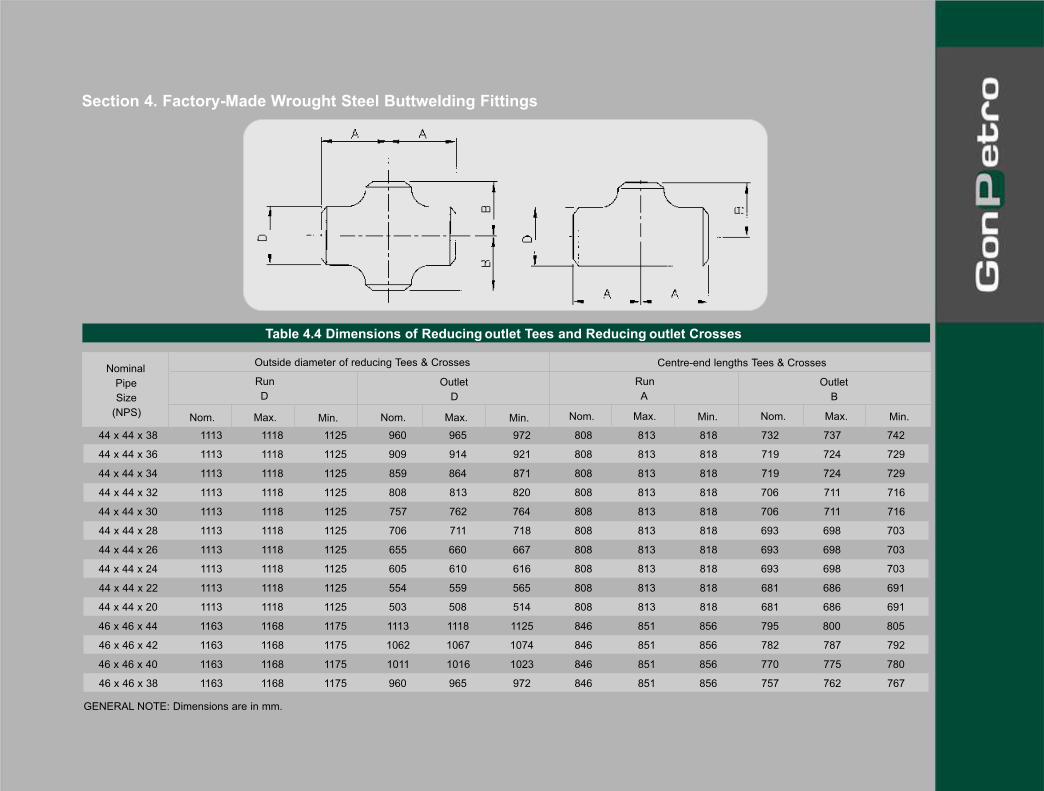
Section 4. Factory-Made Wrought Steel Buttwelding Fittings
44 x 44 x 38 1113 1118 1125 960 965 972 808 813 818 732 737 742
44 x 44 x 36 1113 1118 1125 909 914 921 808 813 818 719 724 729
44 x 44 x 34 1113 1118 1125 859 864 871 808 813 818 719 724 729
44 x 44 x 32 1113 1118 1125 808 813 820 808 813 818 706 711 716
44 x 44 x 30 1113 1118 1125 757 762 764 808 813 818 706 711 716
44 x 44 x 28 1113 1118 1125 706 711 718 808 813 818 693 698 703
44 x 44 x 26 1113 1118 1125 655 660 667 808 813 818 693 698 703
44 x 44 x 24 1113 1118 1125 605 610 616 808 813 818 693 698 703
44 x 44 x 22 1113 1118 1125 554 559 565 808 813 818 681 686 691
44 x 44 x 20 1113 1118 1125 503 508 514 808 813 818 681 686 691
46 x 46 x 44 1163 1168 1175 1113 1118 1125 846 851 856 795 800 805
46 x 46 x 42 1163 1168 1175 1062 1067 1074 846 851 856 782 787 792
46 x 46 x 40 1163 1168 1175 1011 1016 1023 846 851 856 770 775 780
46 x 46 x 38 1163 1168 1175 960 965 972 846 851 856 757 762 767
Table 4.4 Dimensions of Reducing outlet Tees and Reducing outlet Crosses
Nominal
Pipe
Size
(NPS)
Outside diameter of reducing Tees & Crosses
Run
A
Centre-end lengths Tees & Crosses
Outlet
B
Run
D
Outlet
D
Nom. Max. Min. Nom. Max. Min.Nom. Max. Min.Nom. Max. Min.
GENERAL NOTE: Dimensions are in mm.

46 x 46 x 36 1163 1168 1175 909 914 921 846 851 856 757 762 767
46 x 46 x 34 1163 1168 1175 859 864 871 846 851 856 744 749 754
46 x 46 x 32 1163 1168 1175 808 813 820 846 851 856 744 749 754
46 x 46 x 30 1163 1168 1175 757 762 764 846 851 856 732 737 742
46 x 46 x 28 1163 1168 1175 706 711 718 846 851 856 732 737 742
46 x 46 x 26 1163 1168 1175 655 660 667 846 851 856 732 737 742
46 x 46 x 24 1163 1168 1175 605 610 616 846 851 856 719 724 729
46 x 46 x 22 1163 1168 1175 554 559 565 846 851 856 719 724 729
48 x 48 x 46 1214 1219 1226 1163 1168 1175 884 889 894 833 838 843
48 x 48 x 44 1214 1219 1226 1113 1118 1125 884 889 894 833 838 843
48 x 48 x 42 1214 1219 1226 1062 1067 1074 884 889 894 808 813 818
48 x 48 x 40 1214 1219 1226 1011 1016 1023 884 889 894 808 813 818
48 x 48 x 38 1214 1219 1226 960 965 972 884 889 894 808 813 818
48 x 48 x 36 1214 1219 1226 909 914 921 884 889 894 782 787 792
48 x 48 x 34 1214 1219 1226 859 864 871 884 889 894 782 787 792
48 x 48 x 32 1214 1219 1226 808 813 820 884 889 894 782 787 792
48 x 48 x 30 1214 1219 1226 757 762 769 884 889 894 757 762 767
48 x 48 x 28 1214 1219 1226 706 711 718 884 889 894 757 762 767
48 x 48 x 26 1214 1219 1226 655 660 667 884 889 894 757 762 767
48 x 48 x 24 1214 1219 1226 605 610 616 884 889 894 732 737 742
48 x 48 x 22 1214 1219 1226 554 559 565 884 889 894 732 737 742
GENERAL NOTE: Dimensions are in mm.
Table 4.4 Dimensions of Reducing outlet Tees and Reducing outlet Crosses
Nominal
Pipe
Size
(NPS)
Outside diameter of reducing Tees & Crosses
Run
A
Centre-end lengths Tees & Crosses
Outlet
B
Run
D
Outlet
D
Nom. Max. Min. Nom. Max. Min.Nom. Max. Min.Nom. Max. Min.

Section 4. Factory-Made Wrought Steel Buttwelding Fittings
1 ⁄ 2 20 21 22 21 25 29 3.73 21 25 29
3 ⁄ 4 26 27 28 21 25 29 3.91 21 25 29
1 32 33 34 34 38 42 4.55 34 38 42
1 1⁄ 4 41 42 43 34 38 42 4.85 34 38 42
1 1⁄ 2 47 48 49 34 38 42 5.08 34 38 42
2 59 60 61 34 38 42 5.54 40 44 48
2 1⁄ 2 72 73 74 34 38 42 7.01 47 51 55
3 88 89 90 47 51 55 7.62 60 64 68
3 1⁄ 2 101 102 103 60 64 68 8.08 72 76 80
4 113 114 116 60 64 68 8.56 72 76 80
5 140 141 144 69 76 83 9.53 82 89 96
6 167 168 171 82 89 96 10.97 95 102 109
8 217 219 221 95 102 109 12.70 120 127 134
10 270 273 277 120 127 134 12.70 145 152 159
Table 4.5 Dimensions of Caps
Nominal
Pipe
Size
(NPS)
Limiting wall
thickness for
length A1
Min. Nom. Max. Min. Nom. Max. Min. Nom. Max.
Outside Diameter at Bevel
D
Length (1)A1
Length (2)A2
GENERAL NOTE: Dimensions are in mm.

12 321 324 328 145 152 159 12.70 171 178 185
14 353 356 360 158 165 172 12.70 184 191 198
16 403 406 410 171 178 185 12.70 196 203 210
18 454 457 461 196 203 210 12.70 222 229 236
20 503 508 514 222 229 236 12.70 247 254 261
22 554 559 565 247 254 261 12.70 247 254 261
24 605 610 616 260 267 274 12.70 298 305 312
26 655 660 667 257 267 277 ... ... ... ...
28 706 711 718 257 267 277 ... ... ... ...
30 757 762 769 257 267 277 ... ... ... ...
32 808 813 820 257 267 277 ... ... ... ...
34 859 864 871 257 267 277 ... ... ... ...
36 909 914 921 257 267 277 ... ... ... ...
38 960 965 972 295 305 315 ... ... ... ...
40 1011 1016 1023 295 305 315 ... ... ... ...
42 1062 1067 1074 295 305 315 ... ... ... ...
44 1113 1118 1125 333 343 353 ... ... ... ...
46 1163 1168 1175 333 343 353 ... ... ... ...
48 1214 1219 1226 333 343 353 ... ... ... ...
GENERAL NOTES: Dimensions are in mm.
(1) Length A1 applies for thickness not exceeding that given in column “Limiting Wall Thickness for Length A1”. (2) Length A2 applies for thickness greater than given in column “ Limiting Wall Thickness for Length A1”
for NPS 24 and smaller. For NPS 26 and larger, length A2 shall be by agreement between manufacturer and purchaser.
Table 4.5 Dimensions of Caps
Nominal
Pipe
Size
(NPS)
Limiting wall
thickness for
length A1
Min. Nom. Max. Min. Nom. Max. Min. Nom. Max.
Outside Diameter at Bevel
D
Length (1)A1
Length (2)A2

Section 4. Factory-Made Wrought Steel Buttwelding Fittings
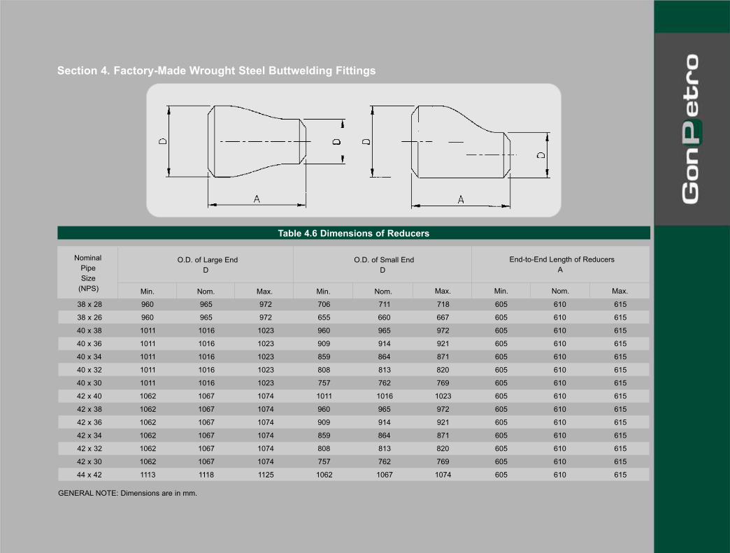
Table 4.6 Dimensions of Reducers
3⁄ 4 x 1⁄ 2 26 27 28 20 21 23 36 38 40
3⁄ 4 x 3⁄ 8 26 27 28 16 17 18 36 38 40
1 x 3⁄ 4 32 33 34 26 27 28 49 51 53
1 x 1⁄ 2 32 33 34 20 21 22 49 51 53
1 1⁄ 4 x 1 41 42 43 32 33 34 49 51 53
1 1⁄ 4 x 3⁄ 4 41 42 43 26 27 28 49 51 53
1 1⁄ 4 x 1⁄ 2 41 42 43 20 21 22 49 51 53
1 1⁄ 2 x 11⁄ 4 47 48 49 41 42 43 62 64 66
1 1⁄ 2 x 1 47 48 49 32 33 34 62 64 66
1 1⁄ 2 x 3⁄ 4 47 48 49 26 27 28 62 64 66
1 1⁄ 2 x 1⁄ 2 47 48 49 20 21 22 62 64 66
2 x 11⁄ 2 59 60 61 47 48 49 74 76 78
2 x 11⁄ 4 59 60 61 41 42 43 74 76 78
2 x 1 59 60 61 32 33 34 74 76 78
Nominal
Pipe
Size
(NPS)
O.D. of Large End
D
O.D. of Small End
D
End-to-End Length of Reducers
A
Min. Nom. Max. Min. Nom. Max. Min. Nom. Max.
GENERAL NOTE: Dimensions are in mm.
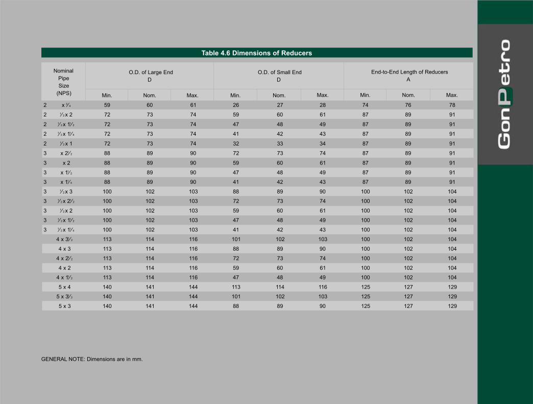
2 x 3⁄ 4 59 60 61 26 27 28 74 76 78
2 1⁄ 2 x 2 72 73 74 59 60 61 87 89 91
2 1⁄ 2 x 11⁄ 2 72 73 74 47 48 49 87 89 91
2 1⁄ 2 x 11⁄ 4 72 73 74 41 42 43 87 89 91
2 1⁄ 2 x 1 72 73 74 32 33 34 87 89 91
3 x 21⁄ 2 88 89 90 72 73 74 87 89 91
3 x 2 88 89 90 59 60 61 87 89 91
3 x 11⁄ 2 88 89 90 47 48 49 87 89 91
3 x 11⁄ 4 88 89 90 41 42 43 87 89 91
3 1⁄ 2 x 3 100 102 103 88 89 90 100 102 104
3 1⁄ 2 x 21⁄ 2 100 102 103 72 73 74 100 102 104
3 1⁄ 2 x 2 100 102 103 59 60 61 100 102 104
3 1⁄ 2 x 11⁄ 2 100 102 103 47 48 49 100 102 104
3 1⁄ 2 x 11⁄ 4 100 102 103 41 42 43 100 102 104
4 x 31⁄ 2 113 114 116 101 102 103 100 102 104
4 x 3 113 114 116 88 89 90 100 102 104
4 x 21⁄ 2 113 114 116 72 73 74 100 102 104
4 x 2 113 114 116 59 60 61 100 102 104
4 x 11⁄ 2 113 114 116 47 48 49 100 102 104
5 x 4 140 141 144 113 114 116 125 127 129
5 x 31⁄ 2 140 141 144 101 102 103 125 127 129
5 x 3 140 141 144 88 89 90 125 127 129
Table 4.6 Dimensions of Reducers
Nominal
Pipe
Size
(NPS)
O.D. of Large End
D
O.D. of Small End
D
End-to-End Length of Reducers
A
Min. Nom. Max. Min. Nom. Max. Min. Nom. Max.
GENERAL NOTE: Dimensions are in mm.

Section 4. Factory-Made Wrought Steel Buttwelding Fittings
5 x 21⁄ 2 140 141 144 72 73 74 125 127 129
5 x 2 140 141 144 59 60 61 125 127 129
6 x 5 167 168 171 140 141 142 138 140 142
6 x 4 167 168 171 113 114 116 138 140 142
6 x 31⁄ 2 167 168 171 101 102 103 138 140 142
6 x 3 167 168 171 88 89 90 138 140 142
6 x 21⁄ 2 167 168 171 72 73 74 138 140 142
8 x 6 217 219 221 167 168 171 150 152 154
8 x 5 217 219 221 140 141 144 150 152 154
8 x 4 217 219 221 113 114 116 150 152 154
8 x 31⁄ 2 217 219 221 101 102 103 150 152 154
10 x 8 270 273 277 217 219 221 176 178 180
10 x 6 270 273 277 167 168 171 176 178 180
10 x 5 270 273 277 140 141 144 176 178 180
Table 4.6 Dimensions of Reducers
Nominal
Pipe
Size
(NPS)
O.D. of Large End
D
O.D. of Small End
D
End-to-End Length of Reducers
A
Min. Nom. Max. Min. Nom. Max. Min. Nom. Max.
GENERAL NOTE: Dimensions are in mm.
10 x 4 270 273 277 113 114 116 176 178 180
12 x 10 321 324 328 270 273 277 200 203 206
12 x 8 321 324 328 217 219 221 200 203 206
12 x 6 321 324 328 167 168 171 200 203 206
12 x 5 321 324 328 140 141 144 200 203 206
14 x 12 353 356 360 321 324 328 327 330 333
14 x 10 353 356 360 270 273 277 327 330 333
14 x 8 353 356 360 217 219 221 327 330 333
14 x 6 353 356 360 167 168 171 327 330 333
16 x 14 403 406 410 353 356 360 353 356 359
16 x 12 403 406 410 321 324 328 353 356 359
16 x 10 403 406 410 270 273 277 353 356 359
16 x 8 403 406 410 217 219 221 353 356 359
18 x 16 454 457 461 403 406 410 378 381 384
18 x 14 454 457 461 353 356 360 378 381 384
18 x 12 454 457 461 321 324 328 378 381 384
18 x 10 454 457 461 270 273 277 378 381 384
20 x 18 503 508 514 454 457 461 505 508 511
20 x 16 503 508 514 403 406 410 505 508 511
20 x 14 503 508 514 353 356 360 505 508 511
20 x 12 503 508 514 321 324 328 505 508 511
22 x 20 554 559 565 503 508 514 505 508 511
Table 4.6 Dimensions of Reducers
Nominal
Pipe
Size
(NPS)
O.D. of Large End
D
O.D. of Small End
D
End-to-End Length of Reducers
A
Min. Nom. Max. Min. Nom. Max. Min. Nom. Max.
GENERAL NOTE: Dimensions are in mm.

Section 4. Factory-Made Wrought Steel Buttwelding Fittings
22 x 18 554 559 565 454 457 461 505 508 511
22 x 16 554 559 565 403 406 410 505 508 511
22 x 14 554 559 565 353 356 360 505 508 511
24 x 22 605 610 616 554 559 565 505 508 511
24 x 20 605 610 616 503 508 514 505 508 511
24 x 18 605 610 616 454 457 461 505 508 511
24 x 16 605 610 616 403 406 410 505 508 511
26 x 24 655 660 667 605 610 616 607 610 613
26 x 22 655 660 667 554 559 565 607 610 613
26 x 20 655 660 667 503 508 514 607 610 613
26 x 18 655 660 667 454 457 461 607 610 613
28 x 26 706 711 718 655 660 667 607 610 613
28 x 24 706 711 718 605 610 616 607 610 613
28 x 20 706 711 718 503 508 514 607 610 613
Table 4.6 Dimensions of Reducers
Nominal
Pipe
Size
(NPS)
O.D. of Large End
D
O.D. of Small End
D
End-to-End Length of Reducers
A
Min. Nom. Max. Min. Nom. Max. Min. Nom. Max.
GENERAL NOTE: Dimensions are in mm.

28 x 18 706 711 718 454 457 461 607 610 613
30 x 28 757 762 769 706 711 718 607 610 613
30 x 26 757 762 769 655 660 667 607 610 613
30 x 24 757 762 769 605 610 616 607 610 613
30 x 20 757 762 769 503 508 514 607 610 613
32 x 30 808 813 820 757 762 769 605 610 615
32 x 28 808 813 820 706 711 718 605 610 615
32 x 26 808 813 820 655 660 667 605 610 615
32 x 24 808 813 820 605 610 616 605 610 615
34 x 32 859 864 871 808 813 820 605 610 615
34 x 30 859 864 871 757 762 769 605 610 615
34 x 26 859 864 871 655 660 667 605 610 615
34 x 24 859 864 871 605 610 616 605 610 615
36 x 34 909 914 921 859 864 871 605 610 615
36 x 32 909 914 921 808 813 820 605 610 615
36 x 30 909 914 921 757 762 769 605 610 615
36 x 26 909 914 921 655 660 667 605 610 615
36 x 24 909 914 921 605 610 616 605 610 615
38 x 36 960 965 972 909 914 921 605 610 615
38 x 34 960 965 972 859 864 871 605 610 615
38 x 32 960 965 972 808 813 820 605 610 615
38 x 30 960 965 972 757 762 769 605 610 615
Table 4.6 Dimensions of Reducers
Nominal
Pipe
Size
(NPS)
O.D. of Large End
D
O.D. of Small End
D
End-to-End Length of Reducers
A
Min. Nom. Max. Min. Nom. Max. Min. Nom. Max.
GENERAL NOTE: Dimensions are in mm.
Section 4. Factory-Made Wrought Steel Buttwelding Fittings
38 x 28 960 965 972 706 711 718 605 610 615
38 x 26 960 965 972 655 660 667 605 610 615
40 x 38 1011 1016 1023 960 965 972 605 610 615
40 x 36 1011 1016 1023 909 914 921 605 610 615
40 x 34 1011 1016 1023 859 864 871 605 610 615
40 x 32 1011 1016 1023 808 813 820 605 610 615
40 x 30 1011 1016 1023 757 762 769 605 610 615
42 x 40 1062 1067 1074 1011 1016 1023 605 610 615
42 x 38 1062 1067 1074 960 965 972 605 610 615
42 x 36 1062 1067 1074 909 914 921 605 610 615
42 x 34 1062 1067 1074 859 864 871 605 610 615
42 x 32 1062 1067 1074 808 813 820 605 610 615
42 x 30 1062 1067 1074 757 762 769 605 610 615
44 x 42 1113 1118 1125 1062 1067 1074 605 610 615
Table 4.6 Dimensions of Reducers
Nominal
Pipe
Size
(NPS)
O.D. of Large End
D
O.D. of Small End
D
End-to-End Length of Reducers
A
Min. Nom. Max. Min. Nom. Max. Min. Nom. Max.
GENERAL NOTE: Dimensions are in mm.

44 x 40 1113 1118 1125 1011 1016 1023 605 610 615
44 x 38 1113 1118 1125 960 965 972 605 610 615
44 x 36 1113 1118 1125 909 914 921 605 610 615
46 x 44 1163 1168 1175 1113 1118 1125 706 711 716
46 x 42 1163 1168 1175 1062 1067 1074 706 711 716
46 x 40 1163 1168 1175 1011 1016 1023 706 711 716
46 x 38 1163 1168 1175 960 965 972 706 711 716
48 x 46 1214 1219 1226 1163 1168 1175 706 711 716
48 x 44 1214 1219 1226 1113 1118 1125 706 711 716
48 x 42 1214 1219 1226 1062 1067 1074 706 711 716
48 x 40 1214 1219 1226 1011 1016 1023 706 711 716
Table 4.6 Dimensions of Reducers
Nominal
Pipe
Size
(NPS)
O.D. of Large End
D
O.D. of Small End
D
End-to-End Length of Reducers
A
Min. Nom. Max. Min. Nom. Max. Min. Nom. Max.
GENERAL NOTE: Dimensions are in mm.