section 34 eurocode 1 en 1991-1-5 section 6 · section 34 eurocode 1 en 1991-1-5 section 6 34.1...
TRANSCRIPT

Topic: User’s Manual/Verification tests - EN1991-1-5_(a)_2.xls page 361
Section 34 Eurocode 1 EN 1991-1-5Section 6
34.1 Temperature changes in bridges
34.1.1 Bridge decks
hree types of bridge superstructures are distinguished in EN 1991-1-5. For the purposes of this Part, bridge decks are grouped as follow:
• Type 1. Steel deck:
— steel box girder
— steel truss or plate girder
• Type 2. Composite deck
• Type 3. Concrete deck:
— concrete slab
— concrete beam
— concrete box girder.
THERMAL ACTIONS Representative values of thermal actions should be assessed by the uniform temperature component (see EN 1991-1-5, Sec. 6.1.3) and the temperature difference components (see EN 1991-1-5, Sec. 6.1.4).
The vertical temperature difference component should generally include the non-linear component. Either Approach 1 or Approach 2 should be used.
34.1.2 Thermal actions
UNIFORM TEMPERATURE COMPONENT The uniform temperature component depends on the minimum and maximum temperature which a bridge will achieve. This results in a range of uniform temperature changes which, in an unrestrained structure would result in a change in element length.
T
EUROCODES SPREADSHEETS STRUCTURAL DESIGN SECTION 34 EUROCODE 1 EN 1991-1-5 SECTION 6
page 362 Topic: User’s Manual/Verification tests - EN1991-1-5_(a)_2.xls
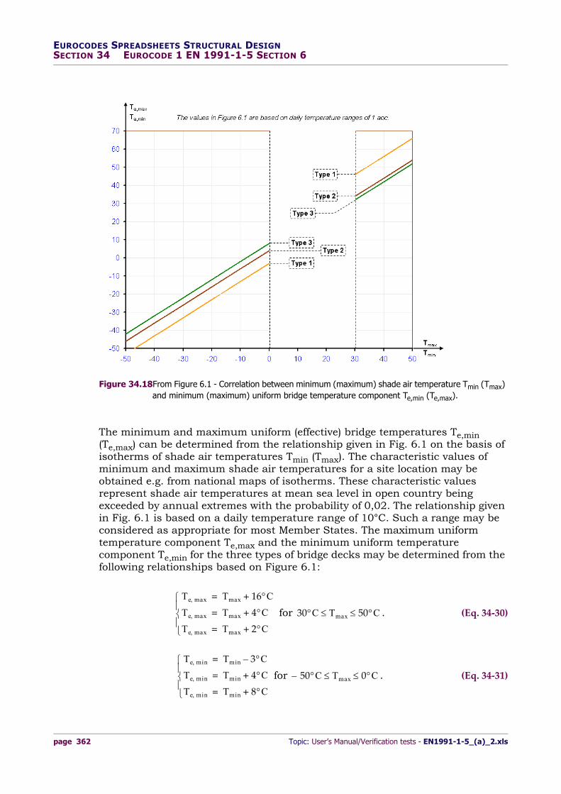
The minimum and maximum uniform (effective) bridge temperatures Te,min (Te,max) can be determined from the relationship given in Fig. 6.1 on the basis of isotherms of shade air temperatures Tmin (Tmax). The characteristic values of minimum and maximum shade air temperatures for a site location may be obtained e.g. from national maps of isotherms. These characteristic values represent shade air temperatures at mean sea level in open country being exceeded by annual extremes with the probability of 0,02. The relationship given in Fig. 6.1 is based on a daily temperature range of 10°C. Such a range may be considered as appropriate for most Member States. The maximum uniform temperature component Te,max and the minimum uniform temperature component Te,min for the three types of bridge decks may be determined from the following relationships based on Figure 6.1:
for . (Eq. 34‐30)
for . (Eq. 34‐31)
Figure 34.18From Figure 6.1 - Correlation between minimum (maximum) shade air temperature Tmin (Tmax) and minimum (maximum) uniform bridge temperature component Te,min (Te,max).
Te max Tmax 16C+=
Te max Tmax 4C+=
Te max Tmax 2C+=
30C Tmax 50C
Te min Tmin 3C–=
Te min Tmin 4C+=
Te min Tmin 8C+=
50– C Tmax 0C

Topic: User’s Manual/Verification tests - EN1991-1-5_(a)_2.xls page 363
EUROCODES SPREADSHEETS STRUCTURAL DESIGNSECTION 34 EUROCODE 1 EN 1991-1-5 SECTION 6
For steel truss and plate girders the maximum values given for Type 1 may be reduced by 3°C.
For construction works located in specific climatic regions as in e.g. frost pockets, additional information should be obtained and evaluated.
Minimum shade air temperature (Tmin) and maximum shade air temperature (Tmax) for the site shall be derived from isotherms in accordance with 6.1.3.2. The National Annex may specify Te,min and Te,max. Figure 6.1 below gives recommended values.
SHADE AIR TEMPERATURE Characteristic values of minimum and maximum shade air temperatures for the site location shall be obtained, e.g. from national maps of isotherms. Information (e.g. maps of isotherms) on minimum and maximum shade air temperatures to be used in a Country may be found in its National Annex. Where an annual probability of being exceeded of 0,02 is deemed inappropriate, the minimum shade air temperatures and the maximum shade air temperatures should be modified in accordance with annex A.
RANGE OF UNIFORM BRIDGE TEMPERATURE COMPONENT The values of minimum and maximum uniform bridge temperature components for restraining forces shall be derived from the minimum (Tmin) and maximum (Tmax) shade air temperatures (see 6.1.3.1 (3) and 6.1.3.1 (4)). The initial bridge temperature T0 at the time that the structure is restrained may be taken from annex A for calculating contraction down to the minimum uniform bridge temperature component and expansion up to the maximum uniform bridge temperature component. Thus the characteristic value of the maximum contraction range of the uniform bridge temperature component, should be taken as:
(Eq. 34‐32)
and the characteristic value of the maximum expansion range of the uniform bridge temperature component, should be taken as:
. (Eq. 34‐33)
34.2 Temperature difference components
34.2.1 Vertical linear component (Approach 1)
For the vertical temperature difference component, two alternative approaches are provided in EN 1991-1-5 which may be nationally selected: (1) linear, or (2) non linear temperature distribution.
The models applied in the linear approach are given in Table 6.1 (“Recommended values of linear temperature difference component for different type of bridge decks for road, foot and railway bridges”) for bridges based on a depth of surfacing of 50 mm. For other surfacing thicknesses, the coefficient ksur should
TN con
TN con T0 Te min–=
TN exp
TN exp Te max T0–=

EUROCODES SPREADSHEETS STRUCTURAL DESIGN SECTION 34 EUROCODE 1 EN 1991-1-5 SECTION 6
page 364 Topic: User’s Manual/Verification tests - EN1991-1-5_(a)_2.xls
be applied (see Table 6.2 - “Recommended values of ksur to account for different surfacing thickness”).
Type of Deck(a)
(a). The values given in the table represent upper bound values of the linearly varying temperature difference component
for representative sample of bridge geometries. The values given in the table are based on a depth of surfacing of 50 mm
for road and railway bridges. For other depths of surfacing these values should be multiplied by the factor ksur. Recom-
mended values for the factor ksur is given in Table 6.2.
Top warmer then bottomTM,heat [°C]
Bottom warmer than topTM,cool [°C]
Type 1.Steel deck
18 13
Type 2.Composite deck
15 18
Type 3.Concrete deck:
- concrete box girder 10 5
- concrete beam 15 8
- concrete slab 15 8
Table 34.9 From Table 6.1 - Recommended values of linear temperature difference component for different type of bridge decks for road, foot and railway bridges.
Road, foot and railway bridges
Type 1 Type 2 Type 3
Surface Thickness
Top warmer then bottom
Bottom warmer then top
Top warmer then bottom
Bottom warmer then top
Top warmer then bottom
Bottom warmer then top
[mm] ksur ksur ksur ksur ksur ksur
unsurfaced 0,7 0,9 0,9 1,0 0,8 1,1
water-proofed(a)
(a). These values represent upper bound values for dark colour.
1,6 0,6 1,1 0,9 1,5 1,0
50 1,0 1,0 1,0 1,0 1,0 1,0
100 0,7 1,2 1,0 1,0 0,7 1,0
150 0,7 1,2 1,0 1,0 0,5 1,0
ballast (750 mm)
0,6 1,4 0,8 1,2 0,6 1,0
Table 34.10 From Table 6.2 - Recommended values of ksur to account for different surfacing thickness.
Topic: User’s Manual/Verification tests - EN1991-1-5_(a)_2.xls page 365
EUROCODES SPREADSHEETS STRUCTURAL DESIGNSECTION 34 EUROCODE 1 EN 1991-1-5 SECTION 6
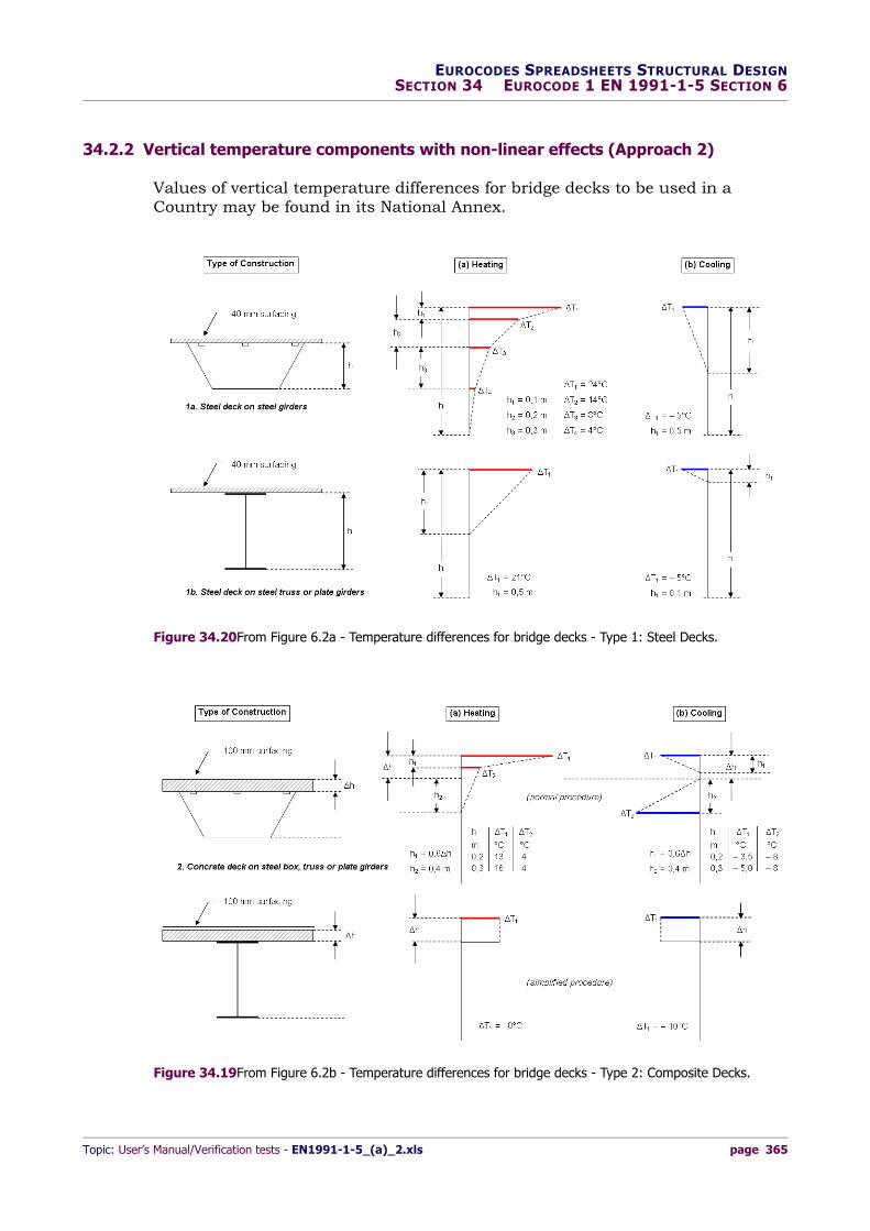
34.2.2 Vertical temperature components with non-linear effects (Approach 2)
Values of vertical temperature differences for bridge decks to be used in a Country may be found in its National Annex.
Figure 34.19From Figure 6.2b - Temperature differences for bridge decks - Type 2: Composite Decks.
Figure 34.20From Figure 6.2a - Temperature differences for bridge decks - Type 1: Steel Decks.

EUROCODES SPREADSHEETS STRUCTURAL DESIGN SECTION 34 EUROCODE 1 EN 1991-1-5 SECTION 6
page 366 Topic: User’s Manual/Verification tests - EN1991-1-5_(a)_2.xls
Recommended values are given in Figures 6.2a/6.2b/6.2c and are valid for 40 mm surfacing depths for deck type 1 and 100 mm for deck types 2 and 3. For other depths of surfacing see Annex B. In these figures “heating” refers to conditions such that solar radiation and other effects cause a gain in heat through the top surface of the bridge deck. Conversely, “cooling” refers to conditions such that heat is lost from the top surface of the bridge deck as a result of re-radiation and other effects.
34.2.3 Simultaneity of uniform and temperature difference components
In some cases, it may be necessary to take into account both the temperature difference (or ) and the maximum range of uniform bridge temperature component (or ) given as:
(Eq. 34‐34)
(Eq. 34‐35)
where the most adverse effect should be chosen. The National annex may specify numerical values of and . If no other information is available, the
Figure 34.21From Figure 6.2c - Temperature differences for bridge decks - Type 3: Concrete Decks.
TM heat TM coolTN exp TN con
TM heat N TN exp+
TM cool N TN con+
M TM heat TN exp+
M TM cool TN con+
N M

Topic: User’s Manual/Verification tests - EN1991-1-5_(a)_2.xls page 367
EUROCODES SPREADSHEETS STRUCTURAL DESIGNSECTION 34 EUROCODE 1 EN 1991-1-5 SECTION 6
recommended values (reduction factors) for and are: , .
Where both linear and non-linear vertical temperature differences are used (see 6.1.4.2) should be replaced by which includes and (see Figures 6.2a/6.2b and 6.2c), where:
• linear temperature difference component
• non-linear part of the difference component
• sum of linear temperature difference component and non-linear part of the temperature difference component.
34.2.4 Bridge Piers: temperature differences
For concrete piers (hollow or solid), the linear temperature differences between opposite outer faces should be taken into account. The National annex may specify values for linear temperature differences. In the absence of detailed information the recommended value is 5°C.
For walls the linear temperature differences between the inner and outer faces should be taken into account. The National annex may specify values for linear temperature differences. In the absence of detailed information the recommended value is 15°C.
34.3 Verification tests
EN1991‐1‐5_(A)_2.XLS. 8.31 MB. Created: 20 November 2013. Last/Rel.-date: 20 November 2013. Sheets:
— Splash
— CodeSec6.
EXAMPLE 34-Q‐ Characteristic thermal actions in bridges ‐ Consideration of thermal actions ‐ test1
Given: Determine the maximum uniform temperature component and the minimum uniform temperature component for the three types of bridge decks determined from the relationships based on Figure 6.1. Let us assume that the characteristic values of minimum and maximum shade air temperatures for a site location (say the city of Birmingham) was obtained e.g. from the UK national maps of isotherms. These characteristic values represent shade air temperatures at mean sea level in open country being exceeded by annual extremes with the probability of 0,02.
[Reference sheet: CodeSec6]‐[Cell‐Range: A1:O1‐A86:O86].
Solution: From the UK isotherms maps (see “Manual for the design of building structures to Eurocode 1 and Basis of Structural Design” ‐ The Institution of Structural Engineers Manual for the design of building structures to Eurocode 1. April 2010), we have (near Birmingham):
N M N 0 35=M 0 35=
TM T TM TE
TM
TE
T
Te maxTe min
Tmin Tmax

EUROCODES SPREADSHEETS STRUCTURAL DESIGN SECTION 34 EUROCODE 1 EN 1991-1-5 SECTION 6
page 368 Topic: User’s Manual/Verification tests - EN1991-1-5_(a)_2.xls
(rounded value for probability p = 0,02)
(rounded value for probability p = 0,02).
Therefore, we get:
for .
for .
The algorithm to draw the graph above is the same. We omit the other two cases (Type 2
example-end
and Type 3).
Tmax 34C=
Tmin 18C–=
Te max Tmax 16C+ 34 16+ 50C= = =
Te max Tmax 4C+ 34 4+ 38C= = =
Te max Tmax 2C+ 34 2+ 36C= = =
30C Tmax 50C
Te min Tmin 3C– 18– 3– 21C–= = =
Te min Tmin 4C+ 18– 4+ 14C–= = =
Te min Tmin 8C+ 18– 8+ 10C–= = =
50– C Tmax 0C
Figure 34.22Excel® output graph (for Bridge deck Type 1).
Topic: User’s Manual/Verification tests - EN1991-1-5_(a)_2.xls page 369
EUROCODES SPREADSHEETS STRUCTURAL DESIGNSECTION 34 EUROCODE 1 EN 1991-1-5 SECTION 6
EXAMPLE 34-R‐ Characteristic thermal actions in bridges ‐ Uniform temperature component ‐ test2
Given: Assuming the same assumptions from the previous example, find the maximum and minimum constant temperature component for the design of bridge bearings (linear behaviour) and expansion joints. Let us assume an initial bridge temperature
at the time that the structure is restrained (see NOTE in Annex A ‐ Sec. A.1(3)). To take into account the uncertainty of the position of the bearings at the reference temperature (see EN 1993‐2, Annex A “Technical specifications for bearings”, Table A.4 “Numerical values for T0”) let us assume a safety term equal to .
[Reference sheet: CodeSec6]‐[Cell‐Range: A90:O90‐A169:O169].
Solution: Note. In the following the main contents of a future Annex E to EN 1990, that would substitute the now Annex A to EN 1993‐2 is presented.
From Expressions (6.1) and (6.2) we get the characteristic value of the maximum contraction and maximum expansion value of the uniform bridge temperature component respectively (bridge deck Type 1):
.
Note For bearings and expansion joints the National Annex may specify the maximum expansion range of the uniform bridge temperature component, and the maximum contraction range of the uniform bridge temperature component, if no other provisions are required. The recommended values are (TN,exp + 20) °C and (TN,con + 20)C°, respectively. If the temperature at which the bearings and expansion joints, are set is specified, then the recommended values are (TN,exp + 10)°C and (TN,con + 10) °C, respectively.
Hence let us assume (say):
.
Design values of the temperature difference (see technical publication: “Bridge Design to Eurocodes Worked examples”. Worked examples presented at the Workshop “Bridge Design to Eurocodes”, Vienna, 4‐6 October 2010. Support to the implementation, harmonization and further development of the Eurocodes. Appendix A: Design of steel bridges. Overview of key content of EN 1993 – G. Hanswille, W. Hansen, M. Feldmann, G. Sedlacek):
.
Bearing with linear behaviour (overall design temperature range):
example-end
.
Ted maxTed min
T0 10C=
T0 10C=
TN con T0 Te min– 10 21– – 31C= = =
TN exp Te max T0– 50 10– 40C= = =
TN con 31 10+ 41C= =
TN exp 40 10+ 50C= =
Ted max T0 F TN exp T0++ 10 1 35 50 10+ + 87 5C= = =
Ted min T0 F TN con– T0– 10 1 35 51 – 10– 55 4C= = =
Td Ted max Ted min– 101 68 9– – 142 9C= = =
EUROCODES SPREADSHEETS STRUCTURAL DESIGN SECTION 34 EUROCODE 1 EN 1991-1-5 SECTION 6
page 370 Topic: User’s Manual/Verification tests - EN1991-1-5_(a)_2.xls
EXAMPLE 34-S‐ Characteristic thermal actions in bridges ‐ Temperature difference components ‐ test3
Given: Assuming the same assumptions form the previous examples, find the vertical linear temperature component (Approach 1) for a bridge deck Type 1 with a surface thickness equal to 100 mm.
[Reference sheet: CodeSec6]‐[Cell‐Range: A173:O173‐A238:O238].
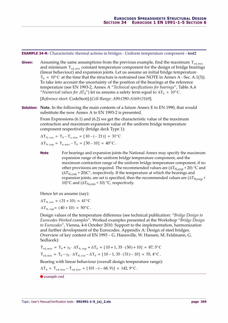
Solution: Entering Table 6.1 ‐ “Recommended values of linear temperature difference component for different types of bridge decks for road, foot and railway bridges” with steel deck Type 1 we get (for ):
– linear temperature difference component (heating): ;
– linear temperature difference component (cooling): .
The values given above represent upper bound values of the linearly varying temperature difference component for representative sample of bridge geometries. The values given in Table 6.1 are based on a depth of surfacing of 50 mm for road and railway bridges.
For other depths of surfacing these values should be multiplied by the factor ksur. Recommended values for the factor ksur are given in Table 6.2. For surface thickness equal to 100 mm and for bridge deck Type 1 we have:
Hence we get (for surface thickness equal to 100 mm):
.
ksur 1=
TM heat 18C=
TM cool 13C=
ksur0 7 (top warmer than bottom)1 2 (bottom warmer then top).
=
TM heat ksur 18C 0 7 18 12 6C= = =
TM cool ksur 13C 1 2 13 15 6C= = =
Figure 34.23Excel® output graph (for Bridge deck Type 1): characteristic values.

Topic: User’s Manual/Verification tests - EN1991-1-5_(a)_2.xls page 371
EUROCODES SPREADSHEETS STRUCTURAL DESIGNSECTION 34 EUROCODE 1 EN 1991-1-5 SECTION 6
EXAMPLE 34-T‐ Characteristic thermal actions in bridges ‐ Vertical temperature (Approach 2) ‐ test3b
Given: Let us consider a bridge deck Type 3 (prestressed precast concrete beam bridge). The height of the precast beam is 36 in = 0.91 m (rounded value). The thickness of the reinforced concrete bridge deck is 25 cm.
Assuming a surfacing depth equal to 100 mm find the temperature difference for heating and cooling (see Figure 6.2c).
[Reference sheet: CodeSec6]‐[Cell‐Range: A242:O242‐A365:O365].
Solution: Entering Table 6.2c with we get:
(a) Heating
with
.
For we have ; ; .
(b) Cooling
.
Linear interpolation for within the range with :
.
Rounded to the first decimal place we get:
; ; ; .
h [m] T1 [°C] T2 [°C] T3 [°C] T4 [°C]
1,0 – 8,0 – 1,5 – 1,5 – 6,3
1,16 T1 T2 T3 T4
1,5 – 8,4 – 0,5 – 1,0 – 6,5
Table 34.11 Values from Figure 6.2c - Temperature differences for bridge decks - Type 3: Concrete decks.
h 0 91 0 25+ 1 16 m= =
h1 0 3 h 0 3 1 16 0 35 m 0 15 m h1 0 15 m= = = =
h2 0 3 h 0 3 1 16 0 35 m= = = 0 10 m h2 0 25 m h2 0 25 m=
h2 0 3 h 0 3 1 16 0 35 m 0 10 m surfacing depth in metres+ 0 20 m= = = =
h 0 8 m T1 13 0C= T2 3 0C= T3 2 5C=
h1 h4 0 20 h 0 20 1 16 0 23 m 0 25 m h1 h4= 0 23 m= = = = =
h2 h3 0 20 h 0 25 1 16 0 29 m 0 20 m h2 h3= 0 29 m= = = = =
Tj 1 0 m h 1 5 m h 1 16 m=
8 4– 8 0– –1 5 1 0–
----------------------------------------T1 8 0– –1 16 1 0–
--------------------------------- T1 8 13C–= =
0 5– 1 5– –1 5 1 0–
----------------------------------------T2 1 5– –1 16 1 0–
--------------------------------- T2 1 18C–= =
1 0– 1 5– –1 5 1 0–
----------------------------------------T3 1 5– –1 16 1 0–
--------------------------------- T3 1 34C–= =
6 5– 6 3– –1 5 1 0–
----------------------------------------T4 6 3– –1 16 1 0–
--------------------------------- T4 6 36C–= =
T1 8 1C–= T2 1 2C–= T3 1 3C–= T4 6 4C–=

EUROCODES SPREADSHEETS STRUCTURAL DESIGN SECTION 34 EUROCODE 1 EN 1991-1-5 SECTION 6
page 372 Topic: User’s Manual/Verification tests - EN1991-1-5_(a)_2.xls
EXAMPLE 34-U‐ Characteristic thermal actions in bridges ‐ Simultaneity of uniform and temperature difference components ‐ test4
Given: Taking into account both the temperature difference (or ) and the maximum range of uniform bridge temperature component (or ) assuming simultaneity, find the most adverse effect to be chosen as input in the FEM analysis. Refer to the data in Example 34‐S (bridge deck Type 1 with ,
).
[Reference sheet: CodeSec6]‐[Cell‐Range: A415:O415‐A509:O509].
Solution: From Expressions (6.1) and (6.2) we get the characteristic value of the maximum contraction and maximum expansion value of the uniform bridge temperature component respectively (bridge deck Type 1):
.
From data in Example 34‐S we have:
(expansion);
(contraction).
From Expressions (6.3) and (6.4), using the given numerical data, we get respectively:
having assumed , for the reduction factors.
Figure 34.24Excel® output graph (for Bridge deck Type 3c): characteristic values.
TM heat TM coolTN exp TN con
Te min 21C–=Te max 50C=
TN con T0 Te min– 10 21– – 31C= = =
TN exp Te max T0– 50 10– 40C= = =
TM heat 12 6C=
TM cool 15 6C=
Load Case 6.3-a: –
Load Case 6.3-b: –
TM heat N TN exp+ 12 6 0 35 40 + 12 6 14+ C= =
TM cool N TN con+ 15– 6 0 35 31– + 15 6 10 9+ – C= =
Load Case 6.4-a: –
Load Case 6.4-b: –
M TM heat TN exp+ 0 75 12 6 40+ 9 45 40+ C= =
M TM cool TN con+ 0 75 15– 6 31– + 11 7– 31– C= =
N 0 35= M 0 75=

Topic: User’s Manual/Verification tests - EN1991-1-5_(a)_2.xls page 373
EUROCODES SPREADSHEETS STRUCTURAL DESIGNSECTION 34 EUROCODE 1 EN 1991-1-5 SECTION 6
Having thus considered four different combinations of load (Case 6.3‐a; Case 6.3‐b; Case 6.4‐a; Case 6.4‐b), we have (see Figure above):
34.4 References [Section 34]
EN 1991-1-5:2003. Eurocode 1: Actions on structures - Part 1-5: General actions - Thermal actions. Brussels: CEN/TC 250 - Structural Eurocodes, November 2003 (DAV)
EN 1991-1-5:2003/AC:2009. Eurocode 1: Actions on structures - Part 1-5: General actions - Thermal actions. Brussels: CEN/TC 250 - Structural Eurocodes, March 2009
Manual for the design of building structures to Eurocode 1 and Basis of Structural Design April 2010. © 2010 The Institution of Structural Engineers
Figure 34.25Excel® output graph (for Bridge deck Type 1): characteristic values.
EUROCODES SPREADSHEETS STRUCTURAL DESIGN SECTION 34 EUROCODE 1 EN 1991-1-5 SECTION 6
page 374 Topic: User’s Manual/Verification tests - EN1991-1-5_(a)_2.xls
JRC Scientific and Technical Reports. Bridge Design to Eurocodes Worked examples. Worked examples presented at the Workshop “Bridge Design to Eurocodes”, Vienna, 4-6 October 2010. Support to the implementation, harmonization and further development of the Eurocodes. Y. Bouassida, E. Bouchon, P. Crespo, P. Croce, L. Davaine, S. Denton, M. Feldmann, R. Frank, G. Hanswille, W. Hensen, B. Kolias, N. Malakatas, G. Mancini, M. Ortega, J. Raoul, G. Sedlacek, G. Tsionis.