section 22 05 00 - common work results for plumbing
TRANSCRIPT

01/06/2017 CAREY GARDENS – CONSTRUCTION ORACLE NO. 8319
COMMON WORK RESULTS FOR PLUMBING 22 05 00 - 1
SECTION 22 05 00 - COMMON WORK RESULTS FOR PLUMBING PART 1 - GENERAL
1.01 RELATED DOCUMENTS
A. Drawings and general provisions of the Contract, including General and Supplementary Conditions and Division 01 Specification Sections, apply to this Section.
1.02 SUMMARY
A. This Section includes the following: 1. Piping materials and installation instructions common to most piping
systems. 2. Transition fittings. 3. Mechanical sleeve seals. 4. Sleeves. 5. Escutcheons. 6. Grout. 7. Painting and finishing. 8. Supports and anchorages.
1.03 DEFINITIONS
A. Finished Spaces: Spaces other than mechanical and electrical equipment rooms, furred spaces, pipe chases, unheated spaces immediately below roof, spaces above ceilings, unexcavated spaces, crawlspaces, and tunnels.
B. Exposed, Interior Installations: Exposed to view indoors. Examples include finished occupied spaces and mechanical equipment rooms.
C. Exposed, Exterior Installations: Exposed to view outdoors or subject to outdoor ambient temperatures and weather conditions. Examples include rooftop locations.
D. Concealed, Interior Installations: Concealed from view and protected from physical contact by building occupants. Examples include above ceilings and in chases.
E. Concealed, Exterior Installations: Concealed from view and protected from weather conditions and physical contact by building occupants but subject to outdoor ambient temperatures. Examples include installations within unheated shelters.
01/06/2017 CAREY GARDENS – CONSTRUCTION ORACLE NO. 8319
COMMON WORK RESULTS FOR PLUMBING 22 05 00 - 2
1.04 SUBMITTALS
A. Product Data: For the following: 1. Transition fittings. 2. Mechanical sleeve seals. 3. Escutcheons.
1.05 DELIVERY, STORAGE, AND HANDLING
A. Deliver pipes with factory-applied end caps. Maintain end caps through shipping, storage, and handling to prevent pipe end damage and to prevent entrance of dirt, debris, and moisture.
1.06 COORDINATION
A. Arrange for pipe spaces, chases, slots, and openings in building structure during progress of construction, to allow for plumbing installations.
B. Coordinate installation of required supporting devices and set sleeves in poured-in-place concrete and other structural components as they are constructed.
C. Coordinate requirements for access panels and doors for plumbing items requiring access that are concealed behind finished surfaces. Access panels and doors are specified in Division 08 Section "Access Doors and Frames."
D. Certifications: Provide manufacturer’s certifications that water heater in contact with the potable water meets the requirements of the Reduction of Lead in Drinking Water Act effective Jan 4, 2014.
PART 2 - PRODUCTS
2.01 PIPE, TUBE, AND FITTINGS
A. Refer to individual Division 22 piping Sections for pip, and fitting materials and joining methods.
2.02 JOINING MATERIALS
A. Refer to individual Division 22 piping Sections for special joining materials not listed below.

01/06/2017 CAREY GARDENS – CONSTRUCTION ORACLE NO. 8319
COMMON WORK RESULTS FOR PLUMBING 22 05 00 - 3
B. Pipe-Flange Gasket Materials: Suitable for chemical and thermal conditions of piping system contents.
1. ASME B16.21, nonmetallic, flat, asbestos-free, 1/8-inch maximum thickness unless thickness or specific material is indicated.
a. Full-Face Type: For flat-face, Class 125, cast-iron and cast-bronze flanges.
b. Narrow-Face Type: For raised-face, Class 250, cast-iron.AWWA C110, rubber, flat face, 1/8 inch thick, unless otherwise indicated; and full-face or ring type, unless otherwise indicated.
C. Flange Bolts and Nuts: ASME B18.2.1, carbon steel, unless otherwise indicated.
2.03 TRANSITION FITTINGS
A. AWWA Transition Couplings: Same size as, and with pressure rating at least equal to and with ends compatible with, piping to be joined.
a. Cascade Waterworks Mfg. Co. b. Dresser Industries, Inc.; DMD Div. c. Ford Meter Box Company, Incorporated (The); Pipe Products Div. d. JCM Industries. e. Smith-Blair, Inc. f. Viking Johnson.
2.04 SLEEVES
A. Galvanized-Steel Sheet: 0.0239-inch minimum thickness; round tube closed with welded longitudinal joint.
2.05 ESCUTCHEONS
A. Description: Manufactured wall and ceiling escutcheons and floor plates, with an ID to closely fit around pipe.
2.06 GROUT
A. Description: ASTM C 1107, Grade B, nonshrink and nonmetallic, dry hydraulic-cement grout.
B. Characteristics: Post-hardening, volume-adjusting, nonstaining, noncorrosive, nongaseous, and recommended for interior and exterior applications.
C. Packaging: Premixed and factory packaged.

01/06/2017 CAREY GARDENS – CONSTRUCTION ORACLE NO. 8319
COMMON WORK RESULTS FOR PLUMBING 22 05 00 - 4
PART 3 - EXECUTION
3.01 PIPING SYSTEMS - COMMON REQUIREMENTS
A. Install piping according to the following requirements and Division 22 Sections specifying piping systems.
B. Drawing plans, schematics, and diagrams indicate general location and arrangement of piping systems. Indicated locations and arrangements were used to size pipe and calculate friction loss, expansion, pump sizing, and other design considerations. Install piping as indicated unless deviations to layout are approved on Coordination Drawings.
C. Install piping in concealed locations, unless otherwise indicated and except in equipment rooms and service areas.
D. Install piping indicated to be exposed and piping in equipment rooms and service areas at right angles or parallel to building walls. Diagonal runs are prohibited unless specifically indicated otherwise.
E. Install piping above accessible ceilings to allow sufficient space for ceiling panel removal.
F. Install piping to permit valve servicing.
G. Install piping at indicated slopes.
H. Install piping free of sags and bends.
I. Install fittings for changes in direction and branch connections.
J. Install piping to allow application of insulation.
K. Select system components with pressure rating equal to or greater than system operating pressure.
L. Install escutcheons for penetrations of walls, ceilings, and floors according to the following:
1. New Piping: a. Piping with Fitting or Sleeve Protruding from Wall: One-piece,
deep-pattern type. b. Bare Piping at Wall and Floor Penetrations in Finished Spaces:
One-piece, stamped-steel type. c. Bare Piping at Ceiling Penetrations in Finished Spaces: One-
piece, stamped-steel type or split-plate, stamped-steel type with concealed hinge and set screw.
d. Bare Piping in Equipment Rooms: One-piece, cast-brass type.

01/06/2017 CAREY GARDENS – CONSTRUCTION ORACLE NO. 8319
COMMON WORK RESULTS FOR PLUMBING 22 05 00 - 5
e. Bare Piping at Floor Penetrations in Equipment Rooms: One-piece, floor-plate type.
2. Existing Piping:
M. Sleeves are not required for core-drilled holes.
N. Install sleeves for pipes passing through concrete and masonry walls and concrete floor and roof slabs.
O. Install sleeves for pipes passing through concrete and masonry walls, gypsum-board partitions, and concrete floor and roof slabs.
1. Cut sleeves to length for mounting flush with both surfaces. a. Exception: Extend sleeves installed in floors of mechanical
equipment areas or other wet areas 2 inches above finished floor level. Extend cast-iron sleeve fittings below floor slab as required to secure clamping ring if ring is specified.
2. Install sleeves that are large enough to provide 1/4-inch annular clear space between sleeve and pipe or pipe insulation. Use the following sleeve materials:
a. Steel Pipe Sleeves: For pipes smaller than NPS 6. 1) Seal space outside of sleeve fittings with grout.
P. Fire-Barrier Penetrations: Maintain indicated fire rating of walls, partitions, ceilings, and floors at pipe penetrations. Seal pipe penetrations with firestop materials. Refer to Division 07 Section for materials.
3.02 PIPING JOINT CONSTRUCTION
A. Join pipe and fittings according to the following requirements and Division 22 Sections specifying piping systems.
B. Remove scale, slag, dirt, and debris from inside and outside of pipe and fittings before assembly.
3.03 EQUIPMENT INSTALLATION - COMMON REQUIREMENTS
A. Install equipment to allow maximum possible headroom unless specific mounting heights are not indicated.
B. Install equipment level and plumb, parallel and perpendicular to other building systems and components in exposed interior spaces, unless otherwise indicated.
C. Install plumbing equipment to facilitate service, maintenance, and repair or replacement of components. Connect equipment for ease of disconnecting, with minimum interference to other installations. Extend grease fittings to accessible locations.

01/06/2017 CAREY GARDENS – CONSTRUCTION ORACLE NO. 8319
COMMON WORK RESULTS FOR PLUMBING 22 05 00 - 6
D. Install equipment to allow right of way for piping installed at required slope.
3.04 PAINTING
A. 09 Sections "Interior Painting" and "Exterior Painting."
B. Damage and Touchup: Repair marred and damaged factory-painted finishes with materials and procedures to match original factory finish.
3.05 ERECTION OF METAL SUPPORTS AND ANCHORAGES
A. Cut, fit, and place miscellaneous metal supports accurately in location, alignment, and elevation to support and anchor plumbing materials and equipment.
B. Field Welding: Comply with AWS D1.1.
END OF SECTION
01/06/2017 CAREY GARDENS – CONSTRUCTION ORACLE NO. 8319
COMMON MOTOR REQUIREMENTS FOR PLUMBING EQUIPMENT 22 05 13 - 1
SECTION 22 05 13 - COMMON MOTOR REQUIREMENTS FOR PLUMBING EQUIPMENT
PART 1 - GENERAL
1.01 RELATED DOCUMENTS
A. Drawings and general provisions of the Contract, including General and Supplementary Conditions and Division 01 Specification Sections, apply to this Section.
1.02 SUMMARY
B. Section includes general requirements for single-phase and polyphase, general-purpose, horizontal, small and medium, squirrel-cage induction motors for use on ac power systems up to 600 V and installed at equipment manufacturer's factory or shipped separately by equipment manufacturer for field installation.
1.03 COORDINATION
A. Coordinate features of motors, installed units, and accessory devices to be compatible with the following:
1. Motor controllers. 2. Torque, speed, and horsepower requirements of the load. 3. Ratings and characteristics of supply circuit and required control
sequence. 4. Ambient and environmental conditions of installation location.
PART 2 - PRODUCTS
2.01 GENERAL MOTOR REQUIREMENTS
A. Comply with NEMA MG 1 unless otherwise indicated.
B. Comply with IEEE 841 for severe-duty motors.

01/06/2017 CAREY GARDENS – CONSTRUCTION ORACLE NO. 8319
COMMON MOTOR REQUIREMENTS FOR PLUMBING EQUIPMENT 22 05 13 - 2
2.02 MOTOR CHARACTERISTICS
A. Duty: Continuous duty at ambient temperature of 40 deg C and at altitude of 3300 feet above sea level.
B. Capacity and Torque Characteristics: Sufficient to start, accelerate, and operate connected loads at designated speeds, at installed altitude and environment, with indicated operating sequence, and without exceeding nameplate ratings or considering service factor.
2.03 POLYPHASE MOTORS
A. Description: NEMA MG 1, Design B, medium induction motor.
B. Efficiency: Energy efficient, as defined in NEMA MG 1.
C. Service Factor: 1.15.
Multispeed Motors: Variable torque.
1. For motors with 2:1 speed ratio, consequent pole, single winding. 2. For motors with other than 2:1 speed ratio, separate winding for each
speed.
D. Multispeed Motors: Separate winding for each speed.
E. Rotor: Random-wound, squirrel cage.
F. Bearings: Regreasable, shielded, antifriction ball bearings suitable for radial and thrust loading.
G. Temperature Rise: Match insulation rating.
H. Insulation: Class F
I. Code Letter Designation:
1. Motors 15 HP and Larger: NEMA starting Code F or Code G. 2. Motors Smaller than 15 HP: Manufacturer's standard starting
characteristic.
J. Enclosure Material: Cast iron for motor frame sizes 324T and larger; rolled steel for motor frame sizes smaller than 324T.

01/06/2017 CAREY GARDENS – CONSTRUCTION ORACLE NO. 8319
COMMON MOTOR REQUIREMENTS FOR PLUMBING EQUIPMENT 22 05 13 - 3
2.04 SINGLE-PHASE MOTORS
A. Motors larger than 1/20 hp shall be one of the following, to suit starting torque and requirements of specific motor application:
1. Permanent-split capacitor. 2. Split phase. 3. Capacitor start, inductor run. 4. Capacitor start, capacitor run.
B. Multispeed Motors: Variable-torque, permanent-split-capacitor type.
C. Bearings: Prelubricated, antifriction ball bearings or sleeve bearings suitable for radial and thrust loading.
D. Motors 1/20 HP and Smaller: Shaded-pole type.
E. Thermal Protection: Internal protection to automatically open power supply circuit to motor when winding temperature exceeds a safe value calibrated to temperature rating of motor insulation. Thermal-protection device shall automatically reset when motor temperature returns to normal range.
PART 3 - EXECUTION (NOT APPLICABLE)
END OF SECTION
01/06/2017 CAREY GARDENS – CONSTRUCTION ORACLE NO. 8319
COMMON MOTOR REQUIREMENTS FOR PLUMBING EQUIPMENT 22 05 13 - 4
BLANK PAGE

01/06/2017 CAREY GARDENS – CONSTRUCTION ORACLE NO. 8319
METERS AND GAUGES FOR PLUMBING PIPING 22 05 19 - 1
Plu
SECTION 22 05 19 - METERS AND GAGES FOR PLUMBING PIPING
PART 1 - GENERAL
1.01 RELATED DOCUMENTS
A. Drawings and general provisions of the Contract, including General and Supplementary Conditions and Division 01 Specification Sections, apply to this Section.
1.02 SUMMARY
A. Section Includes: 1. Thermowells. 2. Dial-type pressure gages. 3. Gage attachments. 4. Test plugs. 5. Test-plug kits.
1.03 ACTION SUBMITTALS
A. Product Data: For each type of product indicated.
1.04 INFORMATIONAL SUBMITTALS
A. Product Certificates: For each type of meter and gage, from manufacturer.
1.05 CLOSEOUT SUBMITTALS
A. Operation and Maintenance Data: For gages to include in operation and maintenance manuals.
PART 2 - PRODUCTS
2.01 PRESSURE GAGES
A. Direct-Mounted, Metal-Case, Dial-Type Pressure Gages:
1. Manufacturers: Subject to compliance with requirements, [provide products by one of the following]:
01/06/2017 CAREY GARDENS – CONSTRUCTION ORACLE NO. 8319
METERS AND GAUGES FOR PLUMBING PIPING 22 05 19 - 2
Plu
a. AMETEK, Inc.; U.S. Gauge. b. Ashcroft Inc. c. Ernst Flow Industries. d. Flo Fab Inc. e. Marsh Bellofram. f. Miljoco Corporation. g. Trerice, H. O. Co. h. Watts Regulator Co.; a div. of Watts Water Technologies, Inc. i. Weiss Instruments, Inc. j. WIKA Instrument Corporation - USA. k. Winters Instruments - U.S.
2. Standard: ASME B40.100. 3. Pressure-Element Assembly: Bourdon tube unless otherwise indicated. 4. Pressure Connection: Brass, with ASME B1.20.1 pipe threads and
bottom-outlet type unless back-outlet type is indicated. 5. Movement: Mechanical, with link to pressure element and connection to
pointer. 6. Dial: Nonreflective aluminum with permanently etched scale markings
graduated in psi 7. Pointer: Dark-colored metal. 8. Accuracy: [Grade A, plus or minus 1 percent
2.02 TEST PLUGS
A. See Editing Instruction No. 1 in the Evaluations for cautions about naming manufacturers. Retain one of first two paragraphs and list of manufacturers below. See Section 016000 "Product Requirements."
B. Manufacturers: Subject to compliance with requirements, provide products by one of the following
1. Flow Design, Inc. 2. Miljoco Corporation. 3. National Meter, Inc. 4. Peterson Equipment Co., Inc. 5. Sisco Manufacturing Company, Inc. 6. Trerice, H. O. Co. 7. Watts Regulator Co.; a div. of Watts Water Technologies, Inc. 8. Weiss Instruments, Inc.
C. Description: Test-station fitting made for insertion into piping tee fitting.
D. Body: Brass or stainless steel with core inserts and gasketed and threaded cap. Include extended stem on units to be installed in insulated piping.
E. Carrying Case: Metal or plastic, with formed instrument padding.
01/06/2017 CAREY GARDENS – CONSTRUCTION ORACLE NO. 8319
METERS AND GAUGES FOR PLUMBING PIPING 22 05 19 - 3
Plu
PART 3 - EXECUTION
3.01 INSTALLATION
A. Install thermowells with socket extending one-third of pipe diameter and in vertical position in piping tees.
B. Install thermowells of sizes required to match thermometer connectors. Include bushings if required to match sizes.
C. Install thermowells with extension on insulated piping.
D. Fill thermowells with heat-transfer medium.
E. Install direct-mounted thermometers in thermowells and adjust vertical and tilted positions.
F. Install remote-mounted thermometer bulbs in thermowells and install cases on panels; connect cases with tubing and support tubing to prevent kinks. Use minimum tubing length.
G. Install direct-mounted pressure gages in piping tees with pressure gage located on pipe at the most readable position.
H. Install remote-mounted pressure gages on panel.
I. Install valve and snubber in piping for each pressure gage for fluids.
J. Install test plugs in piping tees.
K. Install thermometers in the following locations:
1. Inlet and outlet of each water heater. 2. Inlets and outlets of each domestic water heat exchanger. 3. Inlet and outlet of each domestic hot-water storage tank..
L. Install pressure gages in the following locations: 1. Suction and discharge of each domestic water pump.
3.02 CONNECTIONS
A. Install meters and gages adjacent to machines and equipment to allow service and maintenance of, gages, machines, and equipment.

01/06/2017 CAREY GARDENS – CONSTRUCTION ORACLE NO. 8319
METERS AND GAUGES FOR PLUMBING PIPING 22 05 19 - 4
Plu
3.03 ADJUSTING
A. Adjust faces of meters and gages to proper angle for best visibility.
END OF SECTION

01/06/2017 CAREY GARDENS – CONSTRUCTION ORACLE NO. 8319
GENERAL-DUTY VALVES FOR PLUMBING PIPING 22 05 23 - 1
SECTION 22 05 23 - GENERAL-DUTY VALVES FOR PLUMBING PIPING PART 1 - GENERAL 1.01 DESCRIPTION OF WORK
A. Extent of Valve Work is indicated on the Drawings and by the Requirements of this Section.
1.02 SUBMITTALS
A. Product Data
1. Manufacturer's product technical data for each valve. 2. Installation Instructions 3. Include list indicating valve and its application
B. Shop Drawings indicating methods of assembly of components.
PART 2 - PRODUCTS 2.01 MATERIAL
A. All valves, backflow prevention devices etc. that convey drinking water for human consumption must be certified for meeting the requirements of the federally mandated Reduction of Lead in Drinking Water Act of 2014 (not more than a weighted average of .25% lead). Regardless of model numbers indicated herein, provide equivalent models that meet the requirements of the act. All solder used during installation of valves, backflow prevention etc. associated with the potable water system designed for human consumption must also meet the requirements.
B. All valves shall be designed for packing under pressure with valve open or
closed.
C. Valves 2" and under shall be all bronze. Valves 2½" and over shall have iron bodies with bronze mountings (IBBM), and with outside screw and yoke (OS&Y), unless space conditions prevent the use of O.S.& Y. valves, in which case non-rising stem valves may be used.
D. All gate valves shall be of the solid wedge disk type.
E. All valves up to 2" in diameter shall have threaded or solder ends, 2½" in
diameter and over shall have flanged ends.

01/06/2017 CAREY GARDENS – CONSTRUCTION ORACLE NO. 8319
GENERAL-DUTY VALVES FOR PLUMBING PIPING 22 05 23 - 2
F. Iron body flanged-valves, strainers and other items shall be provided with gaskets and sealing as manufactured by Garlock. All flanges shall be drilled for American Standard Association 125 pound standard.
G. All valves, except as otherwise specified, shall be type and number as
specified below:
1. Gate Valves:
Class 125, threaded, bronze body, solid wedge, inside screw non-rising stem, screw-in bonnet: Stockham B-103, Milwaukee 105, Hammond IB645, NIBCO T-113, Crane 438, Lukenheimer 2129, Walworth 4, Apollo Valves 102T, Jenkins 992AJ.
Class 125, Solder end, bronze body, solid wedge, inside screw non-
rising stem, screw-in bonnet: Stockham B-104, Milwaukee 115, Hammond IB647, NIBCO S-113, Crane 1320, Lukenheimer 2133, Walworth 4SJ, Apollo Valves 102S, Jenkins 993AJ.
Class 125, flanged, iron body bronze mounted (IBBM), bolted bonnet,
O.S.& Y., solid wedge: Stockham G-623, Milwaukee F-2885M, Hammond IR1140, NIBCO F-617-0, Crane 465-1/2, Lukenheimer 1430, Walworth 8726F, Apollo Valves 611F, Jenkins 651J.
Class 125, flanged, iron body bronze mounted (IBBM), non-rising
stem, bolted bonnet, solid wedge: Stockham G-612, Milwaukee F-2882M, Hammond IR1138, NIBCO F-619, Crane 461, Lukenheimer 1428, Walworth 8719F, Apollo Valves 610F, Jenkins 326J.
2. Check Valves:
Class 125, threaded ends, bronze body, horizontal swing, bronze
disc: Stockham B-319Y, Milwaukee 509, Hammond IB904, NIBCO T-413-B, Crane 37, Lukenheimer 2144, Walworth 3406, Apollo Valves 161TF, Jenkins 996J.
Class 125, solder ends, bronze body, horizontal swing, bronze disc:
Stockham B-309Y, Milwaukee 1509, Hammond IB912, NIBCO S-413-B, Crane 1340, Lukenheimer 2145, Walworth 3406SJ, Apollo Valves 161S, Jenkins 997AJ.
Class 125, flanged ends, iron body bronze mounted (IBBM), bronze
disc and seat ring, bolted cap, horizontal swing: Stockham G-931, Milwaukee F-2974M, Hammond IR1124, NIBCO F-918-B, Crane 373, Lukenheimer 1790 IBBM, Walworth 8928F, Apollo Valves 910F, Jenkins 624CJ.

01/06/2017 CAREY GARDENS – CONSTRUCTION ORACLE NO. 8319
GENERAL-DUTY VALVES FOR PLUMBING PIPING 22 05 23 - 3
H. Ball valves shall be two-piece, full port, 600 W.O.G., bronze body, chrome
plated bronze or brass ball and Teflon seals, with thread or solder ends. Ball valves shall have a lever handle. Threaded ends ball valve shall be Conbraco Industries, Inc.; Apollo Valves 77C-100, Crane 9211, Milwaukee BA-400, Hammond 8301AN61, NIBCO T-585-70, Dwyer Series BV2MB or Stockham T-255-BR-R and soldered ends ball valve shall be Conbraco Industries, Inc.; Apollo Valves 77C-200, Milwaukee BA-450, Hammond 8311AN61, NIBCO S-585-70 or Stockham S-255 BR-R. Ball valves should be used for up to 2" sizes only.
1. Press-Fit Ball Valves: Valves shall be two-piece bronze body with full
port, chrome or brass plated ball, blow-out proof stem and PTFE or RTFE seats, rated at 600 psi with press fitting ends. Ball Valves shall be Viega Model 2970.10, NIBCO PS585-70, Conbraco Industries, Inc.; Apollo Valves 77W. Ball valves shall have a metal lever handle.
I. Soldered end valves shall be joined using “soft” soldering.
NOTE: All valves of one type, i.e., all gates, or all check valves shall
be of one manufacturer. PART 3 - EXECUTION 3.01 INSTALLATION
A. Install valves in accordance with the manufacturer's instructions. Follow valve manufacturers recommendations when brazing solder end valves.
B. Valves shall be installed so that they shall be readily accessible. It is brought
to the Contractor's attention that all valves shall be so located that they can be easily and safely operated. No valve shall be installed with the stem pointed downward. If, in the opinion of the Authority, valves are so installed as to create a hazardous and unsafe condition, this Contractor shall relocate these valves as directed without additional charge.
1. Valve shall be full size of pipe. Iron body bronze mounted(IBBM),
flanged, outside screw and yoke (OS&Y) valves shall be used on: water service and sprinkler service assemblies, suction and discharge piping for pumps and water distribution piping 2½" and larger. Valves on water distribution piping 2" and smaller shall be brass or bronze body.
C. Gate valves shall be provided at the base of all risers, on all mains, branch
lines, take-offs, drains, etc., and at all pumps, equipment, and at all

01/06/2017 CAREY GARDENS – CONSTRUCTION ORACLE NO. 8319
GENERAL-DUTY VALVES FOR PLUMBING PIPING 22 05 23 - 4
apparatus; so located and arranged as to give complete shut-off and regulating control of all systems piping and apparatus.
1. Ball valves may be substituted for Gate Valves on water distribution
pipes up to 2" in size for risers, branches and hot and cold headers in accessible toilet pipe spaces.
D. Swing check valves shall be installed in horizontal position with hinge pin
horizontally perpendicular to centerline of pipe.
E. All valves shall have the name or trademark of the manufacturer and guaranteed working pressure cast or stamped on the body of the valve. All flanges shall be drilled for American Standards Association 125-pound Standard. Companion flanges for all iron body gate valves, check valves, strainers, etc., shall be iron.
3.02 VALVE APPLICATION SCHEDULE
A. Domestic Hot & Cold Water
1. 2" and Less: Solder or threaded ends; Class 125, bronze body gates; bronze body swing checks.
2. 2½" and up: Flanged ends; Class 125, OS&Y iron body gates; and
iron body swing checks.
C. Gas Piping: Refer to Section – Gas Piping System END OF SECTION
01/06/2017 CAREY GARDENS – CONSTRUCTION ORACLE NO. 8319
HANGERS AND SUPPORTS FOR PLUMBING PIPING AND EQUIPMENT
22 05 29 - 1
SECTION 22 05 29 - HANGERS AND SUPPORTS FOR PLUMBING PIPING AND EQUIPMENT PART 1 - GENERAL 1.01 DESCRIPTION OF WORK
A. Extent of hangers and support Work is indicated by the requirements of this Section.
1.02 SUBMITTALS
A. Submit catalog cuts for each different type of hanger and rod, support and accessory.
B. Submit method of support and hanging for Engineers approval prior to
installation.
C. Submit manufacturer technical data of insert and rod for approval. 1.03 QUALITY ASSURANCE
A. No-Hub piping shall be installed and supported in full compliance with Local Law 100 of 1989.
B. Cast-Iron Soil Pipe Institute (CISIP) Designation B10-1985 and
Designation 301-1985.
C. Manufacturers Standardization Society of The Valve and Fittings Industry (MSS) Compliance: Comply with: MSS SP-58 Pipe Hangers and Supports - Materials, Design and Manufacture. MSS SP-69 Pipe Hangers and Supports - Selection and Application. MSS SP-89 Pipe Hangers and Supports - Fabrication and Installation Practices.
PART 2 - PRODUCTS 2.01 MATERIALS
A. Pipe Hangers and Supports
1. Hangers for horizontal piping (insulated and uninsulated) one inch and smaller, supported from above shall be of malleable iron, adjustable swivel ring type and shall comply with MSS SP-69 Type

01/06/2017 CAREY GARDENS – CONSTRUCTION ORACLE NO. 8319
HANGERS AND SUPPORTS FOR PLUMBING PIPING AND EQUIPMENT
22 05 29 - 2
6. Hangers shall be Anvil International Fig. 104 or the approved equal of Carpenter & Paterson, Inc, Hilti, Inc, or Cooper B-Line, Inc.
2. Hangers for horizontal piping (insulated and uninsulated) and
insulated copper tubing larger than one inch, shall be of carbon steel, adjustable clevis type and shall conform to MSS SP-69 Type 1. Hangers shall be Anvil International Fig. 260, Fig. 260 ISS or the approved equal of Carpenter & Paterson, Inc, Hilti, Inc, or Cooper B-Line, Inc.
3. Hangers for uninsulated horizontal copper tubing one inch and
smaller, supported from above shall be of malleable iron with copper finish, adjustable ring type, complying with MSS SP-69 Type 6, or with MSS SP 69 Type 15 if with Turnbuckle Adjuster. Hangers shall be Anvil International Fig. CT-109 for adjustable ring type and Fig.114 for Turnbuckle Adjuster, or the approved equal of Carpenter & Paterson, Inc, Hilti, Inc, or Cooper B-Line, Inc.
4. Hangers for uninsulated horizontal copper tubing larger than one
inch shall be of carbon steel with copper finish adjustable clevis type, complying with MSS SP 69 Type 1. Hangers shall be Anvil International Fig. CT-65 or the approved equal of Carpenter & Paterson, Inc, Hilti, Inc, or Cooper B-Line, Inc.
5. Support for horizontal pipe runs on roof shall be heavy-duty pipe
rollers. Rollers assembly shall consist of galvanized steel channel track, galvanized steel fittings, washers and nuts, painted cast iron roller and locking devices to maintain pipe location. Assembly shall allow both vertical and horizontal adjustment. Heavy-duty pipe roller support shall be with integral base plate and shall be of the Pate Company, Custom Curb Inc. (Eastern Plant), Miro Industries, Cooper B-Line, Inc. or Portable Pipe Hangers. The support for the gas piping installed horizontally on the roof shall be anchored or secured to the concrete deck. The base plate of the pipe roller support shall be secured to the concrete deck using stainless steel anchors. A 12" galvanized steel with integral base plate or a pipe support base made of polycarbonate plastic with bored holes for securing same to the concrete decking are acceptable
6. Supports for vertical piping and copper tubing shall be double bolt
riser clamps, complying with MSS SP 69 Type 8 with each end having equal bearing on the building structure located as hereinafter specified. Supports shall be Anvil International Fig. 261 for steel pipe and Fig. CT-121 for copper tubing or the approved

01/06/2017 CAREY GARDENS – CONSTRUCTION ORACLE NO. 8319
HANGERS AND SUPPORTS FOR PLUMBING PIPING AND EQUIPMENT
22 05 29 - 3
equal of Carpenter & Paterson, Inc, Hilti, Inc or Cooper B-Line, Inc. If piping is insulated, riser clamp shall be placed under insulation.
7. Where piping is run near the floor and is supported from the floor,
such supports except as otherwise noted shall be of pipe standards with base flange and adjustable top yoke complying with MSS-SP-69 Type 38. Support shall be similar to Carpenter & Paterson, Inc Figure 247 or the approved equal of Anvil International, Hilti, Inc or Cooper B-Line, Inc.
8. Storm drainage leader piping running exposed along the outside
face of building wall shall be supported by offset pipe clamp of carbon steel; Anvil International Fig. 103 or the approved equal of Carpenter & Paterson, Inc, Hilti Inc or Cooper B-Line, Inc.
9. Trapeze type hangers shall be made of 2"x2"x1/4" carbon steel
angle iron with drilled holes and 1/2" hangers rods. In lieu of an angle iron, a strut assembly may also be used for the trapeze kind of hanger support.
10. Bracing for cast iron No-Hub vertical piping (all sizes) and
horizontal piping 6" and larger shall be made up of riser clamps, clevis hangers or two four bolt cast iron socket clamps Anvil International Fig. 595 with cast iron socket clamp washers, Anvil International Fig. 594, or the approved equal of Carpenter & Paterson, Inc, Hilti, Inc or Cooper B-Line, Inc.
Refer to "No-Hub Pipe BRACING" Detail
11. Sway bracing for horizontal No-Hub cast iron piping shall be made up of double bolt riser clamp, complying with MSS SP 69 Type 8, galvanized steel 12" long shields, conforming to MSS SP 69 Type 40, and 1" x 1/8" steel plate. Riser clamp shall be Anvil International Fig. 261 and shields shall be Anvil International Fig. 167 or the approved equal of Carpenter & Paterson, Inc, or Hilti, Inc. or Cooper B-Line, Inc.
Refer to "SWAY BRACING" Detail.
12. At all points of support, a galvanized steel shield shall be provided between the hanger and pipe insulation complying with MSS SP 69 Type 40. Shields shall be Anvil International Fig. 167, Carpenter & Paterson, Inc. Figure 265P or the approved equal of Hilti, Inc or Cooper B-Line, Inc.
B. Expansion bolts for use in existing and new reinforced concrete slabs
shall be as follows:

01/06/2017 CAREY GARDENS – CONSTRUCTION ORACLE NO. 8319
HANGERS AND SUPPORTS FOR PLUMBING PIPING AND EQUIPMENT
22 05 29 - 4
1. “Trubolt” as manufactured by ITW Ramset/Red Head 2. "Kwik Bolts" as manufactured by Hilti, Inc.
3. “Power Stud” as manufactured by Powers Fasteners, Inc.
C. Inserts for use in new conventional reinforced poured concrete slabs shall
be as follows:
1. Insert No. 650 made by Carpenter & Paterson Inc.
2. Insert Fig. 281 made by ITT Anvil International.
3. Insert No. 100 made by C. H. Leibfried Mfg. Corp.
4. Insert No. 96900 Series made by Hilti, Inc.
5. Insert No. B2500 and N2500 Series made by Cooper B-Line, Inc.
D. Inserts for use in new composite metal decks shall be as follows:
Inserts shall be “Bang-It” steel deck insert as manufactured by Powers Fasteners or HCI-MD Cast-In Anchor for Metal Deck as manufactured by Hilti, Inc.
Metal Deck ceiling bolts (T-bars), Carpenter & Paterson, Fig. 143 may be used in lieu of the above specified deck inserts with the approval of the Engineer of Record.
E. Fasteners, as required, shall be as follows:
1. Lag screws or Long screws.
2. Long Expansion bolts
3. Bolts and nuts
PART 3 - EXECUTION 3.01 INSTALLATION

01/06/2017 CAREY GARDENS – CONSTRUCTION ORACLE NO. 8319
HANGERS AND SUPPORTS FOR PLUMBING PIPING AND EQUIPMENT
22 05 29 - 5
A. Supports shall be adequate to securely support the piping and its contents, to prevent vibration and to provide proper allowance for expansion and contraction of the piping.
B. All piping running close to or on walls shall be supported by means of
hanger suspended from heavy angle iron wall brackets. No wall hooks will be permitted.
C. Hanger rods shall be of ample size to support the pipe and its contents
and shall have machine cut American Standard V-threads. At a minimum hanger rod size shall be the same as that recommended by the hanger manufacturer for each sized hanger. Hangers shall be recessed to approved beam clamps, concrete inserts, steel plates or other approved devices. Expansion shields and bolts shall not be used in the ceilings of cinder concrete, but may be used where the shields and bolts are horizontal.
D. Where more than two pipes run parallel, the Contractor may install
trapeze type hangers, constructed of 2" x 2" x 1/4" angle iron or channel strut “ kindorph” and 1/2" hanger rods. Provide holes in the trapeze angle iron as required to accommodate rods for the individual supports. Burning of holes in angle supports is not acceptable. Provide individual supports for piping, where necessary to provide proper pitch. Trapeze type hanger when used with uninsulated copper tubing shall have copper finish. Spacing of trapeze type hangers shall be as required by the smallest size pipe/tube supported by trapeze hanger.
E. At all points of support of insulated piping and tubing a galvanized metal
shield shall be installed between the hanger and pipe insulation. The use of the galvanized metal shield shall be eliminated if the Anvil Fig 260 ISS is utilized. Installation of Anvil Fig 260 ISS: position the pipe on the saddle, notch section of the insulation to fit around the saddle, square cut the adjoining insulation section and butt the mating end to the notched section, finish taping according to standard methods, No galvanized metal shield is required.
F. No piping shall be supported from other pipes, ductwork, electric conduit,
hung ceiling, cinder concrete or work of other trades.
G. When support method is not shown on Drawings, pipes laid underground shall be firmly bedded on solid ground under the body of the pipe. Where suitable bearing cannot be obtained because the ground has been disturbed by excavating, or for any other reason, the pipe shall be supported by concrete piers or by approved brackets secured to the walls. Piers and/or steel brackets shall be installed at not more that 5'-0"
01/06/2017 CAREY GARDENS – CONSTRUCTION ORACLE NO. 8319
HANGERS AND SUPPORTS FOR PLUMBING PIPING AND EQUIPMENT
22 05 29 - 6
intervals. New piping passing under cinder concrete areas shall be supported by hangers secured by means of beam clamps fastened to existing floor beams. Where pipe support spacing is excessive between existing steel, beam clamps shall be fastened to structural members that are installed by this Contractor and approved by the Authority. Removed fireproofing around beams shall be replaced to original condition.
H. Overhead horizontal drains, vents, supply or other piping shall be
supported by adjustable wrought iron, steel or malleable iron hangers. Double locknuts shall be installed all hangers. The metal decks shall not be used for support of piping or equipment.
I. Intervals of supports for horizontal piping shall be as follows:
1. Hub and Spigot Cast iron soil and vent pipe - At 5' intervals and 18"
behind each hub or joint.
2. No-Hub Cast iron soil and vent pipe: - At 5' intervals and within 12" of each joint.
3. Threaded pipe (1¼” or less) - At 8' intervals
4. Threaded pipe (1½” or over) - At 12' intervals
5. Copper tubing (1¼” in. or less) - At 6' intervals
6. Copper tubing (1½” in. or over). At 10' intervals
7. Other Materials--As required for structural stability, service and as
further stipulated in specifications and Drawings.
J. Intervals of supports for vertical piping shall be as follows:
1. All Cast iron soil and vent pipe: At base and at each story height, but in no case at intervals greater than 20'.
2. Threaded pipe: At every other story height, but in no case at
intervals greater than 25'.
3. Copper tubing (Hard Temper): At each story height.
4. Other materials: As for structural stability and service.

01/06/2017 CAREY GARDENS – CONSTRUCTION ORACLE NO. 8319
HANGERS AND SUPPORTS FOR PLUMBING PIPING AND EQUIPMENT
22 05 29 - 7
5. Cast iron storm drainage leader piping exposed along outside face of building wall: At base and at 5' intervals and 18" behind each hub or joint.
K. Inserts and Expansion Bolts
1. Piping and equipment, hung from ceilings shall be properly
supported from the ceiling slabs by means of required number of inserts. Provide inserts before the pouring of the slabs and expansion bolts after concrete is placed and completely cured.
2. Inserts for new conventional reinforced poured concrete slabs shall
be designed for insertion of heavy nuts suitable for screwing up to and including 3/4" rods. Inserts shall not be primed. Install inserts so that hangers will appear true and uniform. Install inserts before the pouring of the concrete.
3. For composite metal deck, consisting of metal deck and
conventional poured reinforced concrete, steel deck inserts or Metal deck ceiling bolts (T-bars) shall be used. Steel deck inserts shall be of a type that is supported by the concrete slab and not by the metal deck. Inserts size shall conform to the size of the hanger rod. Install inserts before the pouring of the concrete.
4. Expansion bolts shall be installed in snug fitting smoothly drilled
holes in accordance with the manufacturer's installation instructions. Expansion bolts shall be installed so that the load acts on the bolts in shear and withdrawal. Expansion bolts shall be carefully located in order to eliminate the risk of damage to concrete, steel reinforcement, and other embedded items. Install in concrete after concrete is placed and completely cured.
5. The Contractor shall take every precaution to furnish and set all
sleeves, wood boxes or other devices that are required for proper installation of his work, before concrete is poured.
The Contractor is responsible for coordination with other trades and
maintaining location of sleeves and inserts during concrete pour.
L. Methods of Fastening: The following rule, except where otherwise specified, shall be observed throughout the entire work: Where fastenings are made to wood, use long screws or lag screw; to brickwork, cement, stone and marble, approved long expansion bolts; to fire-proof block work, approved toggle bolts, and to iron work, approved bolts and nuts. The use of wood plugs and nailing will not be permitted. Sundries used in
01/06/2017 CAREY GARDENS – CONSTRUCTION ORACLE NO. 8319
HANGERS AND SUPPORTS FOR PLUMBING PIPING AND EQUIPMENT
22 05 29 - 8
connection with galvanized iron shall be galvanized. Those in connection with brass work shall be of brass, finished to match the connecting work.
M. Cleaning, painting and installation of hangers and supports shall be done
before the application of fireproofing material. All hanger and support assemblies in their entirety shall be rust proofed and painted. For material and method of painting, refer to Section - Painting.
N. Gas piping installed on the roof: The support shall be anchored or
secured to the concrete deck. 3.02 NO-HUB PIPING - ADDITIONAL REQUIREMENTS
A. Sway bracing shall be provided at changes in direction greater than 45° for pipe sizes 4” and larger.
B. On horizontal piping, additional hangers shall be provided at each
horizontal branch connection.
C. Horizontal piping 6" and larger shall be braced to prevent joint separation.
D. Vertical piping shall be braced at each joint to assure maintaining alignment.
E. Vertical piping shall be secured at base of stack to building structure with
socket clamp and rods or trapeze hangers. END OF SECTION

01/06/2017 CAREY GARDENS – CONSTRUCTION ORACLE NO. 8319
HEAT TRACING FOR PLUMBING PIPING 22 05 33 - 1
SECTION 220533 - HEAT TRACING FOR PLUMBING PIPING
PART 1 - GENERAL
1.1 RELATED DOCUMENTS
A. Drawings and general provisions of the Contract, including General and Supplementary Conditions and Division 01 Specification Sections, apply to this Section.
1.2 SUMMARY
A. Section includes plumbing piping heat tracing for freeze prevention, with the following electric heating cables: 1. Self-regulating, parallel resistance.
B. Contractor shall furnish and install all heat trace cable, associated controller, power and control wiring/conduit and accessories for complete system installation.
1.3 ACTION SUBMITTALS
A. Product Data: For each type of product.
1. Include rated capacities, operating characteristics, and furnished specialties and accessories.
2. Schedule heating capacity, length of cable, spacing, and electrical power requirement for each electric heating cable required.
B. Shop Drawings: For electric heating cable.
1. Include plans, elevations, sections, and attachment details. 2. Include diagrams for power, signal, and control wiring.
1.4 INFORMATIONAL SUBMITTALS
A. Field quality-control reports.
B. Sample Warranty: For special warranty.
01/06/2017 CAREY GARDENS – CONSTRUCTION ORACLE NO. 8319
HEAT TRACING FOR PLUMBING PIPING 22 05 33 - 2
1.5 CLOSEOUT SUBMITTALS
A. Operation and maintenance data: For electric heating cables to include in operation and maintenance manuals.
1.6 WARRANTY
A. Special Warranty: Manufacturer agrees to repair or replace electric heating cable that fails in materials or workmanship within specified warranty period.
1. Warranty Period: Five years from date of Substantial Completion.
PART 2 - PRODUCTS
2.1 SELF-REGULATING, PARALLEL-RESISTANCE HEATING CABLES
A. Manufacturers: Subject to compliance with requirements provide products by one of the following: 1. Chromalox; SRL 2. BriskHeat; SLCAB 3. Trasor Corp.; SRL
B. Comply with IEEE 515.1.
C. Heating Element: Pair of parallel No. 16 AWG, tinned stranded copper bus wires embedded in cross-linked conductive polymer core, which varies heat output in response to temperature along its length. Terminate with waterproof, factory-assembled, non-heating leads with connectors at one end, and seal the opposite end watertight. Cable shall be capable of crossing over itself once without overheating.
D. Electrical Insulating Jacket: Flame-retardant polyolefin.
E. Cable Cover: Tinned-copper braid and polyolefin outer jacket with ultraviolet inhibitor.
F. Maximum Operating Temperature (Power On): 150 deg F
G. Maximum Exposure Temperature (Power Off): 185 deg F
H. Electrical Components, Devices, and Accessories: Listed and labeled as defined in NFPA 70, by a qualified testing agency, and marked for intended location and application.
I. Capacities and Characteristics:

01/06/2017 CAREY GARDENS – CONSTRUCTION ORACLE NO. 8319
HEAT TRACING FOR PLUMBING PIPING 22 05 33 - 3
1. Maximum Heat Output: 5 W/ft. 2. Electrical Characteristics for Single-Circuit Connection:
a. Volts: 120 b. Phase: 1 c. Hertz: 60
2.2 CONTROLS
A. Provide digital heat trace controller with 2 circuits similar to Chromalox ITC2
B. Controller shall be equipped with high resolution display with capacitive touch switches, and LED indication for power and alarm condition
C. Controller shall provide audio/visual alarms for the following conditions: High/Low temperature High/Low Current GFEP Monitoring Sensor monitoring
D. Controller shall be in corrosion resistant , water proof enclosure
2.3 ACCESSORIES
A. Cable Installation Accessories: Fiberglass tape, heat-conductive putty, cable ties, silicone end seals and splice kits, and installation clips all furnished by manufacturer, or as recommended in writing by manufacturer.
B. Provide wall mounting brackets for controller.
C. Warning Tape: Continuously printed "Electrical Tracing"; vinyl, at least 3 mils thick, and with pressure-sensitive, permanent, waterproof, self-adhesive back.
PART 3 - EXECUTION
3.1 EXAMINATION
A. Examine surfaces and substrates to receive electric heating cables for compliance with requirements for installation tolerances and other conditions affecting performance.
1. Ensure surfaces in contact with electric heating cables are free of burrs and sharp protrusions.

01/06/2017 CAREY GARDENS – CONSTRUCTION ORACLE NO. 8319
HEAT TRACING FOR PLUMBING PIPING 22 05 33 - 4
B. Proceed with installation only after unsatisfactory conditions have been corrected.
3.2 INSTALLATION
A. Install electric heating cable on exposed water piping from roof tank. Use slack cable to allow movement without damage to cable.
B. Install electric heating cables according to IEEE 515.1.
C. Set field-adjustable switches and circuit-breaker trip ranges.
D. Provide two RTD sensors per circuit to provide line temperature sensors.
3.3 CONNECTIONS
A. Ground equipment according to Section 260526 "Grounding and Bonding for Electrical Systems."
B. Connect wiring according to Section 260519 "Low-Voltage Electrical Power Conductors and Cables."
3.4 FIELD QUALITY CONTROL
A. Testing Agency: Engage a qualified testing agency to perform tests and inspections.
B. Manufacturer's Field Service: Engage a factory-authorized service representative to test and inspect components, assemblies, and equipment installations, including connections.
C. Perform the following tests and inspections :
1. Perform tests after cable installation but before application of coverings such as insulation, wall or ceiling construction, or concrete.
2. Test cables for electrical continuity and insulation integrity before energizing.
3. Test cables to verify rating and power input. Energize and measure voltage and current simultaneously.
4. Test Controller for all functions and trouble alarms as specified
D. Repeat tests for continuity, insulation resistance, and input power after applying thermal insulation on pipe-mounted cables.
E. Cables will be considered defective if they do not pass tests and inspections.
01/06/2017 CAREY GARDENS – CONSTRUCTION ORACLE NO. 8319
HEAT TRACING FOR PLUMBING PIPING 22 05 33 - 5
F. Prepare test and inspection reports.
3.5 PROTECTION
A. Protect installed heating cables, including non-heating leads, from damage during construction.
B. Remove and replace damaged heat-tracing cables.
END OF SECTION 220533
* * *

01/06/2017 CAREY GARDENS – CONSTRUCTION ORACLE NO. 8319
HEAT TRACING FOR PLUMBING PIPING 22 05 33 - 6
BLANK PAGE

01/06/2017 CAREY GARDENS – CONSTRUCTION ORACLE NO. 8319
IDENTIFICATION FOR PLUMBING PIPING AND EQUIPMENT 22 05 53 - 1
SECTION 22 05 53 - IDENTIFICATION FOR PLUMBING PIPING AND EQUIPMENT PART 1 - GENERAL 1.01 DESCRIPTION OF WORK
A. Work of this Section includes the following:
1. Tags
2. Accessories
3. Charts and Frames
4. Pipeline Identification 1.02 SUBMITTALS
A. Product Data: For each type of product indicated. B. Shop Drawing: 1. Provide list of identification wording, symbols, letter size, and color
coding.
2. Valve numbering scheme; valve Schedules: For each piping system to be included in maintenance manuals.
C. Samples: Submit samples of tags and identification markers for each
different type of service. Samples shall be submitted and approved before installation.
PART 2 - PRODUCTS 2.01 TAGS
A. All controlling valves on hot water, circulation, cold water and gas supply pipes throughout the building, except those at fixtures, shall be furnished with heavy brass tags 2" in diameter, with numbers and the words "Hot" "Circ." "Cold" or "Gas" thereon. The numbers and letters shall be of the block type, indented and filled with durable black compound. The letters shall be 1/4" high and the numbers shall be 1/2" high. The tags on circulation (Circ) pipe valves shall be numbered the same as the hot water valve controlling the riser or branch to which the circulation pipe is connected.
01/06/2017 CAREY GARDENS – CONSTRUCTION ORACLE NO. 8319
IDENTIFICATION FOR PLUMBING PIPING AND EQUIPMENT 22 05 53 - 2
B. Tags shall be as manufactured by Seton Nameplate Corp., Brimar Industries, Inc., Marking Services Inc., EMED Co., Inc.
2.02 CHARTS AND FRAMES
A. The numbers on valves for hot, circ., cold and gas shall be arranged in the following manner:
In cellar or basement commencing with No. 1
B. If it should occur that the number of valves on any floor exceed the number
of tags provided for said floor, then a letter must be added which would read, for example 100A or 100B, and so on, until all valves on the floor are properly numbered, but in no case shall a number be applied other than as herein stated.
C. The number of each and every valve throughout the building shall be plainly
typed on approved heavy paper. Opposite each number shall be set the location of the valve bearing that number, also the fixture or fixtures controlled by that valve. The charts shall be framed in an approved glazed frame. The frames shall be made of 1" wide oak picture molding with wood back, and shall be finished with natural color varnish with screw-eyes and wire for hanging same, and shall be submitted to the Authority for approval before installation.
2.03 PIPELINE IDENTIFICATION
A. Identification shall be in accordance with “Scheme for Identification of Piping System ANSI A13.1" and OSHA safety color regulation.
B. Markers shall be snap-on type as manufactured by Seton Nameplate Corp.,
(Setmark System) EMED Co., Inc., Brimar Industries, Inc., Marking Services Inc. Markers shall completely encircle the pipe with a substantial overlap. No adhesive shall be used. They shall be manufactured of U.L. approved, self-extinguishing plastic. When the pipe including insulation (if any) is 6" diameter and larger, markers shall be strap on type.
C. Provide identification for piping, and equipment.
D. Pipe shall be lettered in accordance with the schedule below. Lettering shall
be located at the supply side of each valve and branch connection and at intervals of not over 20'(10' on fire lines and gas lines in the basement and cellar) on straight runs of pipe. Provide flow arrows for all piping at each marker. Adjacent to the legend, stencil the size of the pipe. Background and letter colors are as follows: Yellow with black letters, green with white letters, blue with white letters and red with white letters.

01/06/2017 CAREY GARDENS – CONSTRUCTION ORACLE NO. 8319
IDENTIFICATION FOR PLUMBING PIPING AND EQUIPMENT 22 05 53 - 3
STENCIL SCHEDULE
Service Stencil Designation Background Color
Cold Water Cold Water Green
Cold Water Cold Water Green Make-up Make-up
Sanitary Sewer San. Sewer Green
Storm Sewer Storm Sewer Green
Waste Piping Waste Green
Vent Piping Vent Green
Gas Gas Safety Yellow
Gas Vent Gas Vent Safety Yellow
Pump Discharge Pump Disch. Green
E. The nature of service of all machinery, equipment, tanks, pumps, and other
apparatus shall be stenciled in 2" high letters unless otherwise directed. 2.04 ACCESSORIES
A. Accessories for attaching tags to their respective hot, circ., cold, and gas valves shall include solid brass jack chain with adjustable open and close links and solid brass S-Hooks.
B. Jack chains and S-hooks shall be as manufactured by Seton Nameplate
Corp., EMED Co., Inc., Brimar Industries, Inc., Marking Services Inc. PART 3 - EXECUTION 3.01 INSTALLATION
A. Attach solid brass tags to their respective hot, circ., cold and gas valves with jack chain and S-Hooks.
C. Hang the charts and frames where directed, as follows:
01/06/2017 CAREY GARDENS – CONSTRUCTION ORACLE NO. 8319
IDENTIFICATION FOR PLUMBING PIPING AND EQUIPMENT 22 05 53 - 4
1. One (1) in Boiler Room or Mechanical Room
2. One (1) in Manager's Office
3. One (1) on each floor
END OF SECTION

01/06/2017 CAREY GARDENS – CONSTRUCTION ORACLE NO. 8319
PLUMBING INSULATION 22 07 19 - 1
SECTION 22 07 19 - PLUMBING INSULATION PART 1 - GENERAL 1.01 DESCRIPTION OF WORK
A. Provide non-conducting insulation, including accessories, on the following piping and apparatus.
1. All concealed and exposed hot water supply piping (which is not laid
in the ground) including circulation and booster piping, tempered water piping, flanges, fittings and valves.
2. All concealed and exposed cold water supply piping (which is not laid
in the ground) including flanges, fittings and valves.
3. All concealed and exposed horizontal runs and off-sets of storm water piping, except when laid in the ground or when located in non-occupied spaces in the basement. All fittings and vertical off-sets associated with the foregoing pipe shall also be insulated.
1.02 SUBMITTALS
A. Product Data
Submit manufacturer's product data for insulation materials, adhesives, mastics and cements. Include installation details for valves, fittings, pipes and all other item to be insulated. No material shall be delivered to the site prior to being approved.
B. Certificates from the manufacturer stating compliance with the following:
Insulation, finishing facings or jackets, adhesives, mastics and cements are asbestos free and all materials installed have composite fire and smoke hazard ratings, 25 & 50 respectively, to meet the requirements of the Building Code of the City of New York.
1.03 QUALITY ASSURANCE
A. Regulatory Requirements
All insulation, vapor barriers, as well as the adhesives and finishing facings or jackets used herewith shall have a flame spread rating not over 25 without evidence of continued progressive combustion, and shall have a smoke developed rating not higher than 50. Flame spread rating and
01/06/2017 CAREY GARDENS – CONSTRUCTION ORACLE NO. 8319
PLUMBING INSULATION 22 07 19 - 2
smoke developed rating shall be as defined in the N.Y.C. Building Code. All materials installed shall have composite fire and smoke hazard ratings to meet requirements of that Code. All insulation shall comply with the 2016 New York State Energy Code Standard and shall have MEA numbers as required or Approved Agency Certification listed and/or label.
B. Asbestos Prohibition
All products provided under this Section shall be asbestos, lead and mercury free.
C. Installer's Qualifications
Firm with at least three years of successful installation experience on projects with the piping and mechanical equipment insulation similar to that required for this Project.
1.04 DELIVERY, STORAGE AND HANDLING
A. Deliver insulation, coverings, cements, adhesives and coatings to the site in factory-fabricated containers with the manufacturer's stamp, or label, affixed showing fire hazard ratings of the products and brand.
B. Store insulation in original wrappings and protect from any damage.
1.05 TEMPERATURE REQUIREMENT
A. Apply adhesive, sealers, coating, and all other items and accessories at the proper temperature as recommended by the manufacturer. If ambient conditions are not acceptable, provide temporary heat as required for proper installation without any delay to the Project completion.
1.06 COORDINATION
A. Coordinate size and location of supports, hangers, and insulation shields
B. Coordinate clearance requirements with piping installer for piping insulation application and equipment installer for equipment insulation application. Establish and maintain clearance requirements for installation of insulation and field-applied jackets and finishes and for space required for maintenance.
C. Coordinate installation and testing of heat tracing.
PART 2 - PRODUCTS

01/06/2017 CAREY GARDENS – CONSTRUCTION ORACLE NO. 8319
PLUMBING INSULATION 22 07 19 - 3
2.01 MANUFACTURERS
A. Insulation, fiberglass fitting cloth, bands and casings, manufactured by Certain-Teed Corp., Johns Manville, Owens-Corning Fiberglass Corp., Knauf Insulation, Armacell LLC; AP Armaflex., Pittsburgh Corning Corp. or The Dow Chemical Company, complying with the requirements of the specifications will be approved. Adhesives manufactured by Benjamin Foster Co., Epolux Manufacturing Corp., Armacell LLC or Insul-Coustic (Division of Birma Products Corp.), complying with the requirements of the specifications will be approved. Pre-molded fiberglass fittings as manufactured by Hamfab Inc., complying with the requirements of the specification will be approved. Vapor barrier and weatherproofing jacket manufactured by Venture Tape Corp., or Polyguard Products Inc. complying with the requirements of the specifications will be approved.
2.02 MATERIALS
A. Adhesives and Sealants for Insulation: All adhesives and sealants used on interior building insulation shall comply with the South Coast Air Quality Management District (SCAQMD) Rule #1168; VOC limits shall comply with the limits indicated in Table 1 of LEED Version 2.2, Indoor Environmental Quality Section, Credit EQ-4.1. Those limits correspond to an effective date of the SCAQMD Rule #1168 of July 1, 2005, and Rule Amendment date of January 7, 2005.
B. Products shall not contain asbestos, lead, mercury, or mercury
compounds. C. Foam insulation materials shall not use CFC or HCFC agents in the
manufacturing process.
D. Piping Insulation
1. All piping insulation shall be: One-piece molded sectional fiberglass having a nominal 4-pound density. Its thermal conductivity shall not exceed 0.27 BTU per inch/h x ft2 x °F per the 2016 New York State Energy Conservation Construction Code. Insulations shall have factory-applied all-service jacket (ASJ) and adhesive used to adhere the jacket to the insulation. It shall be suitable for use on piping up to 370°F.
2. Fiber Free Elastomeric Foam: closed-cell material having a thermal
conductivity of 0.25 at 75°F. mean temperature and suitable for use on piping up to 180°F; the equal of AP Armaflex.
01/06/2017 CAREY GARDENS – CONSTRUCTION ORACLE NO. 8319
PLUMBING INSULATION 22 07 19 - 4
3. Fiberglas Paper-Free ASJ Pipe Insulation: Molded fibrous glass pipe insulation with factory applied paper free all service jacket and double adhesive lap seal closure system, rated for a maximum service temperature of 850°F. Circumferential joints shall be sealed with paper free butt strips that are compatible with the required facing. Stapling shall not be required to complete the closure. Manufacturer's data regarding thickness constraints in relation to operating temperature shall be followed. On cold systems, vapor barrier shall be provided. All penetrations and exposed ends of insulation shall be sealed with mold resistant vapor barrier mastic.
E. Insulation and accessories
1. For valves, fittings, etc. for hot water piping, cold water piping,
drainage and vent piping shall include the following:
a. One pound density fiberglass blanket.
b. Segments of pipe insulation.
c. Pre-molded fiberglass fittings.
d. No. 20 gage galvanized steel annealed wire.
e. Insulating cement.
f. In lieu of the cement coat, and fiberglass blanket material or segment of pipe insulation on valves and fittings; the use of Zeston product, an ultra violet resistant, 20-mil thick, one-piece PVC fitting cover with pre-cut insulation inserts, HI-Lo-Temp, as manufactured by Manville, shall be accepted.
2. For water meters, provide the following:
a. 1.5 pound density fiberglass blanket.
b. 2" hexagonal galvanized mesh wire.
c. Insulating cement.
F. Jacket and accessories
1. Over insulation on hot water piping, install the following:
a. White kraft paper outer surface bonded to aluminum foil and
reinforced with fiberglass yarn.
01/06/2017 CAREY GARDENS – CONSTRUCTION ORACLE NO. 8319
PLUMBING INSULATION 22 07 19 - 5
b. Outward clinch coated 9/16" staples.
c. 3/4" wide aluminum bands.
d. Aluminum casing, 0.16" thick.
e. PVC Plastic: Zeston, one piece molded type fitting covers and
jacketing material, gloss white. Connections: Tacks, pressure sensitive color matching vinyl tape.
2. Over insulation on valves, fittings, etc. for hot water piping, include
the following:
a. Fiberglass fitting cloth which shall be 20 X 20 yarns per inch fiberglass mesh.
b. Lagging adhesive shall be Epolux No. 336, Foster 30-36.
c. PVC Plastic: Zeston, one piece molded type fitting covers and
jacketing material, gloss white. Connections: Tacks, pressure sensitive color matching vinyl tape.
3. Over insulation for cold water piping, drainage and vent piping,
install the following:
a. White kraft paper outer surface bonded to aluminum foil and reinforced with fiberglass yarn.
b. Insulation adhesive.
c. Aluminum casing, .016" thick.
e. Elastomeric closed cell fiber free foam with no vapor barrier is
also acceptable.
d. Vapor barrier and weatherproofing jacket shall be a laminated five-ply self-adhesive material; weather resistant, high puncture and tear resistant. The product shall be used both indoors and outdoors, shall have zero permeability, and shall be manufactured with mold inhibitors: VentureClad 1577CW-All Grade or Alumaguard Lite or Alumaguard “All Weather” LT.
01/06/2017 CAREY GARDENS – CONSTRUCTION ORACLE NO. 8319
PLUMBING INSULATION 22 07 19 - 6
4. Over insulation on valves and fittings for drainage and vent piping and over valves, fittings, water meters for cold water, the following shall be included:
a. Glass cloth.
b. Vapor barrier coating shall be Foster 30-80.
G. Special protection: At all points of support the following shall be included:
1. Rigid calcium silicate pipe insulation having a minimum twelve (12)
pound density. Blocks shall be 11/2" thick.
2. Galvanized metal shields as manufactured by Carpenter & Paterson, Fig. 265 P or Anvil International Fig. 167. Shields shall be 18 gage for pipe sizes up to and including 5" and 16 gage for larger sizes.
PART 3 - EXECUTION 3.01 GENERAL REQUIREMENTS
A. Insulation shall be installed only after tests of the piping systems as specified in Section: Tests have been successfully completed.
B. Valves shall be insulated up to the packing unit.
C. Unions shall not be insulated.
D. Fire Seal Application: Where pipes pass through fire walls, fire partitions,
fire rated pipe chase walls or floors above grade, insulation shall be interrupted and a fire seal shall be provided as specified in Section: Firestopping.
E. All necessary insulating material not specified shall be as recommended by
the manufacturer of the insulation. 3.02 INSTALLATION
A. Thermal Insulation for Piping
1. Insulation for hot water piping shall be 1" thick for pipe sizes up to and including 3" and shall be 11/2" thick for larger sizes. Insulation for cold water piping shall be 1" thick for pipe sizes up to and including 2", and shall be 11/2" thick for larger pipe sizes. Insulation for horizontal runs and off-sets including fittings and vertical off-sets

01/06/2017 CAREY GARDENS – CONSTRUCTION ORACLE NO. 8319
PLUMBING INSULATION 22 07 19 - 7
of storm water piping shall be of the thickness specified for cold water piping. Thicknesses indicated are based on insulation having a conductivity (k) not exceeding 0.27 BTU per inch/h x ft2 x °F
2. Valves, fittings, etc. for hot & cold water piping shall be insulated as
follows:
a. For pipe sizes smaller than 4”, wrap firmly under a minimum of a 3:1 compression, with 1 pound density fiberglass blanket, to a thickness equal to adjoining insulation. Secure with No. 20 gage galvanized steel annealed wire. Finish with a smooth coat of insulating cement. In addition, insulating cement (except for cold water) applied in thickness equal to the adjoining pipe insulation material may also be used on valves & fittings.
b. For pipe sizes 4" and larger, fit segments of pipe insulation
equal in thickness to adjoining insulation and secure with No 20 gage galvanized annealed steel wire. Finish with a smooth coat of insulating cement.
c. In lieu of the foregoing methods, the use of pre-molded
fiberglass fittings of the same thickness as adjoining pipe insulation will be accepted. Secure with No. 20 gauge galvanized annealed steel wire and finish with a smooth coat of insulating cement.
d. In lieu of the above a, b and c, the use of pre-formed PVC
fitting covers with factory pre-cut Hi-Lo Temp insulation insert of the same thickness as adjoining pipe insulation will be accepted. Valves, fittings, etc. shall be insulated by applying the PVC fitting covers of the same thickness as adjoining pipe insulation with the proper factory precut Hi-Lo Temp insulation insert to the pipe fitting, valve, etc. The ends of the Hi-Lo Temp insulation insert shall be tucked snugly into the throat of the fitting, valve etc. and the edges adjacent to the pipe covering tufted and tucked in, fully insulating the pipe fitting, valve, etc. The PVC fitting cover [in conjunction with a mastic vapor barrier for cold water only] shall then be applied and shall be secured by tack fastening, and then taping the ends to the adjacent pipe covering. Where the operating temperature exceeds 250°F, 2 or more layers of the Hi-Lo Temp insulation inserts shall be applied prior to the installations of the PVC cover. The first layer shall be
01/06/2017 CAREY GARDENS – CONSTRUCTION ORACLE NO. 8319
PLUMBING INSULATION 22 07 19 - 8
applied with a few wrappings of fiberglass yarn to eliminate voids or hot spots.
3. All water meters shall be covered with a 1", 1.5 pound density
fiberglass blanket under a minimum of 3:1 compression. Over this insulation use a 2" hexagonal galvanized mesh wire, tightly stretched and secured in place with edges tied together. Finish with approved insulating cement 1/4" thick in one coat, troweled to a smooth finish.
B. Facing or Jackets
1. Hot Water Piping
a. Insulation on concealed and exposed hot water piping shall
have a jacket of white kraft paper outer surface bonded to aluminum foil and reinforced with fiberglass yarn. Longitudinal laps shall be secured with outward clinch coated 9/16" staples on 4" maximum centers. Circumferential joints shall be firmly butted and wrapped with a 3" minimum wide strip of the jacketing material securely stapled in place. In lieu of staples, longitudinal laps and circumferential joint butt strips may be smoothly secured with lagging adhesive. Jackets shall be additionally secured with 3/4" wide aluminum bands installed on 12" (maximum) centers.
b. Insulation on hot water valves, fittings, etc., shall have a jacket
of fiberglass fitting cloth smoothly adhered with lagging adhesive. Lap cloth on itself and adjoining insulation facing. Lap shall be 1" on pipe sizes up to and including 3" and 2" on large pipe sizes.
2. Cold Water Piping
a. Insulation on piping shall have a vapor barrier jacket of white
kraft paper outer surface bonded to aluminum foil and reinforced with fiberglass yarn or of self-adhesive material. Longitudinal laps and butt strips shall be smoothly secured with insulation adhesive. Vapor barrier jackets on insulation must be applied with a continuous unbroken vapor seal. The use of staples on vapor barrier jacketed insulation is not permitted. The use of Elastomeric closed cell fiber free foam with no vapor barrier is acceptable.
b. Insulation on valves, fittings, water meter, etc., shall be vapor
sealed by applying glass cloth embedded between two 1/16"

01/06/2017 CAREY GARDENS – CONSTRUCTION ORACLE NO. 8319
PLUMBING INSULATION 22 07 19 - 9
thick coats of vapor barrier coating. Lap seal glass cloth at least 2" on itself and the adjoining insulation.
c. The ends of cold water pipe insulation shall be sealed off at
all flanges, fittings, valves and interval of 21' on continuous runs of pipe with Foster fire resistant vapor barrier coating BF 30-80.
3. Horizontal Drainage Lines
a. Insulation on horizontal runs and off-sets including fittings,
vertical off-sets of storm water piping shall have a vapor barrier jacket as described for cold water piping in subparagraph 2 above. The use of Elastomeric closed cell fiber free foam with no vapor barrier is acceptable.
b. The ends of drainage pipe insulation shall be sealed off at all
fittings and at intervals of 21 feet on continuous run of pipe with Foster fire resistant vapor barrier coating BF 30-80.
C. Insulation and Protection at Points of Support
1. Install inserts made from rigid calcium silicate pipe insulation, in lieu
of pipe insulation specified in Paragraph A above, at all points of support. Inserts shall be not less than 12" long and of thickness equal to adjoining insulation. A jacket shall be installed over the insert with longitudinal laps and butt strips for circumferential joints smoothly secured with insulation adhesive. Jacket shall provide vapor barrier where required.
2. Install galvanized steel shields between supports and inserts.
Shields shall be formed to fit the insulation and shall extend up to the center line of the pipe and of the length specified for the inserts. Supports shall not pierce the insulation and all vapor barriers shall be unbroken and continuous.
3.03 PROTECTION AND REPLACEMENT
A. Replace insulation damaged during construction which cannot be repaired satisfactorily, including units with vapor barrier damage and moisture saturated units.

01/06/2017 CAREY GARDENS – CONSTRUCTION ORACLE NO. 8319
PLUMBING INSULATION 22 07 19 - 10
B. Protection
Insulation worker shall advise Contractor of required protection for insulation work during remainder of construction period, to avoid damage and deterioration.
3.04 PAINTING A. Insulation on all piping and fittings, exposed in Boiler Room shall be given
two (2) coats paint. Color of paint shall be as per the schedule in Section Tags, Charts and Identification, Article 2.03, Par. D.
B. Insulation on all piping and fittings, exposed in finished spaces shall be
given two (2) coats of paint, the color of which shall match the adjacent surroundings.
C. For additional materials and method of painting, refer to Section- Painting.
3.05 LABELING
A. After the finished coat of paint has been applied to the insulation, this contractor shall do all pipeline identification labeling as specified in Section- "Tags, Charts and Identification."
END OF SECTION

01/06/2017 CAREY GARDENS – CONSTRUCTION ORACLE NO. 8319
DOMESTIC WATER PIPING – HOT WATER 22 11 16 - 1
SECTION 22 11 16 - DOMESTIC WATER PIPING – HOT WATER
PART 1 - GENERAL 1.01 DESCRIPTION OF WORK
A. Extent of hot water supply Work is indicated on the Drawings and by the requirements of this Section.
1.02 CODES AND STANDARDS
A. Comply with applicable portions of the Building Code of the City of New York, and the New York City/State Energy Conservation Construction Code (NYCECC/NYSECCC). Where requirements for products, materi-als, equipment, methods and other portion of the work specified herein exceed minimum requirements of N.Y.C. Building Code, the Contractor shall comply with such requirements specified herein, unless specifically approved otherwise by the Authority.
B. The contractor shall comply with the Reduction of Lead in Drinking Water
Act. Beginning on January 4, 2014, a federal law known as “Reduction of Lead in Drinking Water Act” takes effect. This law requires that faucet, plumbing fixtures, pipe and pipe fittings must conform to” lead free” criteria level whenever these plumbing related products are employed for delivery of potable water for human consumption.
1. The law makes it unlawful for any person, including a contractor, to
introduce into commerce any pipe, pipe fitting, plumbing fixture, faucet that is not lead free.
a. “Lead free” content is intended to mean not more than 0.2%
lead when applied in connection to solder and flux and not more than 0.25 percent of the weighted average of lead when used with respect to the wetted surfaces of pipes, pipe fittings, plumbing fixtures and faucets.
b. The section of the federal act that applies to solder and flux,
0.2% lead content, went into effect back in August of 1998; and for the most part soldering product being sold in today’s market complies with the law.
c. The requirement for .25% weighted average of lead when
applied to the wetted surfaces of pipes, pipe fittings, plumb-ing fixtures and faucet is the new section of the law that re-quires special attention from a contractor.

01/06/2017 CAREY GARDENS – CONSTRUCTION ORACLE NO. 8319
DOMESTIC WATER PIPING – HOT WATER 22 11 16 - 2
2. To ensure compliance with “Reduction of Lead in Drinking Water
Act”, a procedure for determining lead content was developed. The calculation procedure works as follows:
a. “For each wetted component, the percentage of lead in the
component shall be multiplied by the ratio of the wetted sur-face area of that component to the total wetted surface area of the entire product to arrive at the weighted percentage of lead of the component. The weighted percentage of lead of each wetted component shall be added together, and the sum of these weighted percentages shall constitute the weighted average lead content of the product. The lead con-tent of the material used to produce wetted components shall be used to determine compliance with paragraph (1)(B) [Paragraph 1B Describes 0.25% Requirement For 0.25 % Lead Content]”
b. As an alternative to implementing the lead content calcula-
tion, the contractor may choose to demonstrate compliance with the act by requiring from manufacturer documentation certifying that products are lead free based on either calcula-tion or tests or third party certification.
1.03 SUBMITTALS
A. Submit Shop Drawings/Product Literature for the following: 1. Master Tempering Valves 2. Thermometers 3. Vacuum Breakers
B. Submit manufacturer's instructions for installation of thermometers.
C. Certifications
1. Lead-free Certifications: Provide manufacturer’s certification that valves, water sub-meter etc. in contact with the potable water meet the requirements of the Reduction of Lead in Drinking Water Act ef-fective Jan 4, 2014.
PART 2 - PRODUCTS

01/06/2017 CAREY GARDENS – CONSTRUCTION ORACLE NO. 8319
DOMESTIC WATER PIPING – HOT WATER 22 11 16 - 3
2.01 MATERIALS
A. Piping shall be as specified in Section 22 05 00, 22 11 16, 22 11 17, 22 11 20, 22 13 16 and shall also comply with the following:
1. Type "L" Copper Tubing (Hard Drawn) shall be for use on water
distribution piping above ground, excluding short branch supplies to fixtures.
2.03 MASTER TEMPERING VALVE
A. Master tempering valve for controlling hot water temperature delivered to plumbing fixtures shall be of the thermostatic type complying with ASSE 1017. Valve shall be of bronze body construction and shall come equipped with unions, check-stops and strainers to screen out water-born debris. Valve shall be capable to control and maintain the set point temperature of 105°F with a minimum flow of 1 gpm when fitted into a re-circulating line with a pump. Master tempering valve(s) shall be from one of the following series, or approved equal with the specific Basis of Design model number indicated on the Drawings:
1. Powers - Hydroguard XP–Hi/Lo – Series LFSH1430 – Temperature
Range 90°F to 160oF.
2. Lawler – Model #800 Series – High–Low – Temperature Range 90oF to 120oF.(Lead free)
3. Leonard – XL-200-20-RF-LF-DT-NYC New Generation High Low
System - Temperature Range 90oF to 120oF.
B. The size of hot and cold inlets and tempered water outlet shall be as indi-cated on the Drawings.
2.04 THERMOMETERS
A. Provide thermometers in locations as indicated on the Drawings to record temperatures of the following:
1. Building hot water circulating line 2. Building hot water supply line downstream of 3-way mixing valve
3. Hot water storage tank temperature.
01/06/2017 CAREY GARDENS – CONSTRUCTION ORACLE NO. 8319
DOMESTIC WATER PIPING – HOT WATER 22 11 16 - 4
B. Thermometers shall be gas actuated dial thermometers having a bulb 6"
long with a brass separable socket, 1" NPT filled with a conducting medi-um. The dial shall be white enameled, black figured, approximately 41/2” in diameter, graduated from 30oF to 240oF. The case shall be cast alumi-num, with polished chrome ring. Thermometers shall be Weksler No. 433BKCL or Weiss G45VA406 or approved equal.
2.05 VACUUM BREAKERS
A. Refer to Section 22 11 17. PART 3 - EXECUTION 3.01 HOT WATER PIPING
A. Connect to the hot water heater and extend, suspended from the cellar or basement ceiling, brass pipe or type "L" copper tubing hot water mains of the sizes indicated on the Drawings and extend from same the required number of branches to supply apparatus, etc
3.02 MASTER TEMPERING VALVES
A. The master tempering valve shall be installed and connected to the hot water header at top of the heater and to the cold water header with sepa-rate branches of pipe and fittings. Install brass and/or bronze "Y" type strainers on the hot and cold water inlet piping to mixing valve. The hot and cold water branches shall each be fitted with gate and check valves, drain faucets and unions.
B. Master tempering valve shall be set to deliver water at a temperature of
105oF, unless otherwise noted.
C. The end of the tempering valve, where the adjusting screw is located, shall have a clear space of 24" with any fixed object. This clearance will allow access for regulating and servicing of the valve.

01/06/2017 CAREY GARDENS – CONSTRUCTION ORACLE NO. 8319
DOMESTIC WATER PIPING – HOT WATER 22 11 16 - 5
D. Extend from mixing valve with a tempered water header provided with the required tees for thermometer bulb, regulating bulb and connections for tempered water supply to fixtures throughout the building.
E. Install O.S. & Y valved by-pass between hot water header and tempered
water header. 3.03 THERMOMETERS
A. Thermometers shall be installed in accordance with the manufacturer's in-structions. Location of thermometers shall be as indicated on the Draw-ings or as directed by the Authority.
END OF SECTION
01/06/2017 CAREY GARDENS – CONSTRUCTION ORACLE NO. 8319
DOMESTIC WATER PIPING – HOT WATER 22 11 16 - 6
BLANK PAGE

01/06/2017 CAREY GARDENS – CONSTRUCTION ORACLE NO. 8319
SECTION 22 11 17 - DOMESTIC WATER PIPING - COLD WATER PART 1 - GENERAL 1.01 DESCRIPTION OF WORK
A. Extent of cold water supply Work is indicated on the Drawings and by the requirements of this Section.
B. All valves and water sub-meter etc. that convey drinking water for human
consumption must be certified for meeting the requirements of the federally mandated Reduction of Lead in Drinking Water Act of 2014 (not more than a weighted average of .25% lead). Regardless of model numbers indicated herein, provide equivalent models that meet the requirements of the act. All solder used during installation of valves, backflow prevention etc. associated with the potable water system designed for human consumption must also meet the requirements.
1.02 CODES AND STANDARDS
A. The Building Code of the City of New York.
B. Department of Environmental Protection (D.E.P.) Agency of the City of New York.
C. Where requirements for products, materials, systems, equipment, methods
and other portion of the work specified herein exceed minimum requirements of regulatory agencies having jurisdiction over the construction work, contractor shall comply with such requirements specified herein, unless specifically approved otherwise by the Authority.
1.04 SUBMITTALS
A. Submit Shop Drawings for the following:
1. Strainers
2. Pressure Gauges
3. Water Sub-Meter 4. Wall Hydrants 5. Backflow Preventers DOMESTIC WATER PIPING – COLD WATER 22 11 17 - 1

01/06/2017 CAREY GARDENS – CONSTRUCTION ORACLE NO. 8319
PART 2 - PRODUCTS 2.01 MATERIALS
A. Piping shall be as specified in Section: Plumbing Piping and shall also comply with the following:
1. Type "L" Copper Tubing (Hard Drawn) shall be for use on water
distribution piping, excluding short branch supplies to fixtures, above ground.
2.02 STRAINERS
A. Y-Strainers
1. Except as otherwise noted strainers shall be full size Y-pattern provided with removable cylindrical or conical screens of monel or stainless steel and suitable flanges or tapping to connect with the piping they serve.
2. Strainers shall be cast iron on iron and steel piping and bronze on
brass or copper piping except as otherwise noted in other sections of the specifications.
3. Screen perforations for water shall be 1/16" (0.57 diameter) for pipe
sizes up to 3" and 1/8" for 4" and above.
B. Provide valves dirt blow-off connection for each Y-strainer. The blow-off connection shall terminate with a gate valve and nipple.
C. Bronze Y-Strainers shall be Sarco Type BT, Mueller Steam Specialty No.
352, Conbraco Industries Inc.; Apollo Valves Model 59.
D. Cast iron Y-Strainers shall be Sarco Type IT, Mueller Steam Specialty No.11, Conbraco Industries Inc.; Apollo Valves Model TCG.
2.03 PRESSURE GAGES
A. Provide where shown on the Drawings or required, in addition to those called for with specific pieces of equipment, pressure gauges with stainless steel movement, 4½" diameter dials, 0-100 psi dial range, phosphor bronze bourdon tube and black enamel cast aluminum, safety case. Gauge dial
DOMESTIC WATER PIPING – COLD WATER 22 11 17 - 2

01/06/2017 CAREY GARDENS – CONSTRUCTION ORACLE NO. 8319
shall be micro adjustable. Pressure gauges shall have an accuracy of 1/2 of 1% of the scale range and shall be Weksler Royal gauge Model No. AA14-4, Weiss Model No. 4UGN.
B. All gauges shall be equipped with pigtail siphons and shutoff cocks.
C. Siphons and cocks to be of same manufacture as gauges.
D. No permanent gauge shall be used while the Contractor is making
hydrostatic tests on any portion of the piping systems. 2.04 WATER GAGES
A. Water gages shall be threaded for 1/2" connection, shall have four guards, 5/8" diameter glass and shall be as manufactured by Ernst Gage Co. All fittings in connection with gages shall be finished brass.
2.05 VACUUM BREAKERS AND BACKFLOW PREVENTION
A. Atmospheric Vacuum Breakers shall be Febco 710A and 715A, Watts 288A series, or Conbraco 38-100 series or Wilkins Model 35. Atmospheric-type vacuum breakers shall conform to ASSE 1001 or CAN/CSA B64.1.1
1. Poppets shall be molded plastic (polypropylene) or unicellular hi-car
rubber.
2. Vacuum Breaker shall be rated to 150 psi working pressure and shall withstand water temperature to 212oF. The uni-cellular hi-car rubber is recommended in 1/2" and 3/4" for low flow applications. The vacuum breaker cannot be subjected to more than 12 hours of constant pressure.
B. Pressure Vacuum Breaker Assemblies shall consist of an approved check
valve, vacuum relief, inlet and discharge shutoff and field testing cocks. All nipples and other fittings shall be red brass. Vacuum breakers shall be rated to 150 psi working pressure and shall withstand water temperatures to 170oF. The vacuum relief valve must be of brass construction with a spring loaded diaphragm member to assure positive opening of air inlet when back-siphonage occurs. Pressure Vacuum Breakers shall be Febco 765, Watts 800, or Conbraco/Apollo 40-500 series or Wilkins Model 420. In sizes above 2", two check valves are required.
C. Reduced Pressure Backflow Preventer shall consist of two separately spring
loaded "Y" type check valves, a differential pressure relief valve, two shut-off valves, and test cocks for field-testing.
DOMESTIC WATER PIPING – COLD WATER 22 11 17 - 3

01/06/2017 CAREY GARDENS – CONSTRUCTION ORACLE NO. 8319
1. Backflow Preventer shall be tested and certified under A.S.S.E. No.
1013, AWWA C511 and USC manual. It shall be rated to 150 psi (minimum) working pressure and 110oF water temperature.
2. Types of Reduced Pressure Zone Backflow Preventer shall be Wilkins
575 3/4”–2” Model 975XL and 2½”-12” Model 375A, Watts 909, Febco 825Y, Conbraco/Apollo 40-200 series.
3. Double detector check valve assembly on the fire service branch and
a domestic-type meter on the domestic branch may be utilized in lieu of a fire-service compound type water meter or electromagnetic meter for the combined service. All detector check valves approved for use in the City of New York shall comply with the latest applicable requirements of the D.E.P. Bureau of Water and Energy Conservation and the Bureau of Water Supply and Wastewater Collection, Cross Connection Control Unit as well as having UL and Factory Mutual (FM) approval.
2.06 WALL HYDRANTS
A. Wall hydrants shall be nickel bronze with nickel bronze casing, polished nickel bronze face, brass operating parts throughout, adjustable wall clamp, renewable nylon seat, 3/4" HPT standard hose outlet with integral vacuum breaker, 3/4" IPS male thread ground joint union elbow adapter, nickel bronze access box and nickel bronze hinged cover with locking device. Furnish and deliver four (4) operating keys to the Custodian. Wall hydrants shall be Josam 71000, Jay R. Smith 5509-E, Wade W-8625, Zurn Z-1300.
2.07 WATER SUB-METER
A. A sub-meter that provides for accurate flow measurement of potable water supplied to the boilers shall be fitted on water lines feeding the plumbing fixtures and noted equipment. The sub-meter shall be a non-intrusive kind that requires no cutting of pipe or drilling of a hole. The device shall not be in contact with the water and thus it shall not cause pressure drop.
B. Design of the sub-meter shall use transit-time ultrasonic technology along with
transducers to provide for flow totalizing (gallons used) and flow rate (gpm) in real time. Sub-meter (s) shall be wall –mounted and capable for +1% accurate flow measurement of clean liquids, suitable for liquids that contain small amounts of suspended solids or particle in sizes smaller than 100 um in order to make a measurement. Sub-meter shall be able to operate in temperatures ranging from 32°F to 212°F and come equipped with a device that emits pulse signals.
DOMESTIC WATER PIPING – COLD WATER 22 11 17 - 4

01/06/2017 CAREY GARDENS – CONSTRUCTION ORACLE NO. 8319
C. The clamp-on sub-meter shall contain a display that is LCD with backlight.
Indication for flow rate and flow accumulator shall be displayed in English (US) units.
D. Clamp-on transducers that are strapped to the water lines and wired directly
to the sub-meter electronics enclosure must be provided as part of the potable water sub-metering system.
E. Enclosure shall be weather-resistant, NEMA 4X or IP65. It shall be
constructed of stainless steel
F. Power requirement for the sub-meter is 90 VAC.
G. Approved Models: STUF -300FxB by SHENITECH or TFX by Dynasonics. 2.08 CURB VALVES AND BOXES
A. Curb valves and boxes with covers for all water service pipes shall be as approved by the Department of Environmental Protection.
B. Curb valves shall be of the gate type, non-rising stem valves, designed for a
minimum of 150 lbs. per square inch working pressure.
C. Valves shall be equipped with an operating nut at least 1¼" square. A wrench or key for operating each valve shall be left with the Custodian or with a representative of the Authority.
2.09 SIGNS FOR FIRE SERVICE
A. Sign for fire curb valve shall be brass or bronze and shall have a white background with 1" red letters reading "Automatic Sprinkler Shutoff Valve 2 feet opposite this sign".
B. Sign for main sprinkler control valve inside the building shall be an enameled
sign, 4" x 10". The sign shall have a white background with 1" red letters reading "Main Sprinkler Valve".
C. Signs over toggle switch operating the remote control valve inside the fire
pump room shall be an enameled sign, 4” x 10”. The signs shall have a white background with 1” red letters reading “DOMESTIC WATER VALVE ON” on top the switch and “DOMESTIC WATER VALVE OFF” at bottom of the switch.
DOMESTIC WATER PIPING – COLD WATER 22 11 17 - 5
01/06/2017 CAREY GARDENS – CONSTRUCTION ORACLE NO. 8319
PART 3 - EXECUTION 3.01 COLD WATER DISTRIBUTION PIPING
A. The distributing mains shall be suspended from the overhead structural floor slab or steel beam and shall be of the sizes and arrangements indicated on the Drawings. The branches to fixtures in the cellar and basement shall be connected to the distributing mains and all shall be of the sizes indicated on the Drawings. Each branch shall be installed with a gate valve.
B. Install gate valves, unions and 1/2" drain bibbs on all branches from main to
risers; see Drawings. Branches connected to risers shall be connected in such a manner that the riser is free to expand upward for its entire length.
1. Water hammer arresters shall be installed on all mains, risers and
branches to fixtures where indicated on the Drawings and when required.
2. Ball valves may be substituted for gate valves on distribution
branches and risers for pipe sizes up to and including 2".
C. The headers supplying flushometers to water closets shall be run in pipe spaces or as indicated on the Drawings and shall be 1½" for two (2) water closets, 2" for three (3) or four (4) water closets and 2½" for five (5) to ten (10) water closets with 1¼" branch for each water closet flushometer and 3/4" for urinal flushometer (1¼" for barrier-free urinal). Each flush header branch from riser shall be provided with a gate valve. The header shall be extended with a shock absorber where indicated on the Drawings and when required.
3.04 VACUUM BREAKERS AND BACKFLOW PREVENTION
A. Install Atmospheric Vacuum Breakers where indicated on the Drawings. Atmospheric Vacuum Breakers may be used as protection against cross connections where the vacuum breaker is not subjected to back pressures due to pumps or gravity and must be installed on the discharge side of the shutoff. They must be installed a minimum of 6" above the highest overflow level. It must be installed with the air inlet in a level position.
C. Reduced Pressure Backflow Preventers:
1. Provide adequate clearance for testing and maintenance.
2. Use proper drainage provision.
DOMESTIC WATER PIPING – COLD WATER 22 11 17 - 6

01/06/2017 CAREY GARDENS – CONSTRUCTION ORACLE NO. 8319
3. Protect from freezing.
4. Provide adequate support.
5. Installation on domestic water service must be submitted for approval to the New York City D.E.P. Bureau of Water and Energy Conservation and the Bureau of Water Supply and Wastewater Collection, Cross-Connection Control Unit.
3.05 WALL HYDRANTS
A. Wall Hydrants shall be set in exterior walls at the time the walls are being erected. The Contractor shall ensure that each wall hydrant is at the location and elevation noted on the Drawings.
3.07 DISINFECTION
A. The Contractor shall be responsible for bacteriological examination and disinfection of the potable water system in accordance with the provisions of Section: Tests, Article 3.03.
3.08 TESTING
A. The Contractor is to engage a third party certified back flow preventer tester to perform testing and inspection of all back flow prevention devices and system and file the appropriate forms with NYC DEP (NYC GEN 215B) for the main back flow prevention device and NYC DOB (OP-129) for the secondary devices.
3.11 WATER SUB-METER
A. Follow the manufacturer’s instructions for installation of the sub-meter. The recommended spacing between transducers and the laying-out or method of installation: Z-method (two transducers on opposite sides of the pipe), V-method (two transducers on the same side) that is outlined in the installers’ guide must be adhered to. Provide cable of sufficient length to wire the transducer to the electronic enclosure. The electronic enclosure shall be installed neatly at a location shown on the Drawings or as approved by the Engineer of Record in a location where the meter can be read.
END OF SECTION DOMESTIC WATER PIPING – COLD WATER 22 11 17 - 7

01/06/2017 CAREY GARDENS – CONSTRUCTION ORACLE NO. 8319
BLANK PAGE
DOMESTIC WATER PIPING – COLD WATER 22 11 17 - 8

01/06/2017 CAREY GARDENS – CONSTRUCTION ORACLE NO. 8319
DOMESTIC WATER PUMPS 22 11 23 - 1
SECTION 22 11 23 - DOMESTIC WATER PUMPS
PART 1 - GENERAL 1.01 DESCRIPTION OF WORK
A. Provide all electrical motor-driven pumps, compressed air and vacuum systems, appurtenances and tanks as indicated on the Drawings and as specified herein.
1.02 SUBMITTALS
A. Manufacturer's installation and operation instructions, catalog sheets, specifications, and maintenance manuals for each item specified.
B. Shop Drawings.
1. Cuts of each pump, indicating parts and materials.
2. Motor data.
3. Cuts of each control panel and components
4. Wiring Diagrams
5. Cuts of each float switch assembly
6. Cuts of each water pressure booster system
C. Submit a compliance affidavit, if all items in subparagraph B match con-
tract documents. Manufacturer’s technical product data submission will be required if a substitution is proposed.
D. Certificates:
1. Approved Agency Certification listed and/or label for tank lining 2. Certified pump test curves 3. Manufacturer’s data report for tank pressure testing
E. Maintenance data: 1. Spare parts
2. Maintenance manual
01/06/2017 CAREY GARDENS – CONSTRUCTION ORACLE NO. 8319
DOMESTIC WATER PUMPS 22 11 23 - 2
1.03 QUALITY ASSURANCE
A. Each pump control panel must have UL label and panel wiring shall com-ply with the latest New York City Electrical Code.
PART 2 – PRODUCTS 2.01 MOTORS
A. Provide motors and motor starters in accordance and in compliance of the requirements of Section 22 05 13, 26 29 13
2.02 PUMPS-GENERAL
A. The casing for pumps shall be of close-grained cast iron for bronze fitted pumps or bronze on all bronze pumps. The waterways must have large cross-section areas with smooth turns so that the water will pass through at a low velocity without shock. Suitable openings shall be provided for the suction gauge, discharge gauge, air vent and cock. Openings shall be tapped and plugged.
B. Unless otherwise specified, the shaft shall be of the best grade of 18-8
stainless steel and of ample size to transmit safely the maximum amount of power required. Shaft shall be provided with ample keyway and key to accurately hold the impeller in place. The impeller shall be secured to the shaft using a nut and locking washer. The impeller shall be hydraulically balanced for all pressures and shall be of bronze, hand finished on the in-side, machine turned and polished on the outside, dynamically balanced at all speeds, and with liberal keyway to fasten to shaft. Coupling shall be flanged and of the flexible type with pin and rubber bushing construction. That portion of the shaft passing through the pump casing and stuffing boxes shall be encased in a bronze sleeve, securely fastened to the shaft.
C. A name-plate showing the serial number, discharge GPM and Head of
each pump shall be attached to the respective pump. The necessary wir-ing and controlling devices will be furnished and installed complete under the Electrical Division, unless otherwise specified.
D. Certified test curves of the pumps to be installed shall be provided for all
pumps in accordance with Section 22 11 23.
E. Flexible Hose Connections
Where indicated on Drawings or specified, connect the pumps to piping with flexible hose as manufactured by Chicago Metal Hose Co., Tite Flex

01/06/2017 CAREY GARDENS – CONSTRUCTION ORACLE NO. 8319
DOMESTIC WATER PUMPS 22 11 23 - 3
Metal Hose Co., Anaconda Metal Hose Co. or Flex-Hose Co., Inc. Corru-gated inner tube and outer shield of wire braid: Stainless steel or Bronze with carbon steel or copper end connections. The flexible hose shall have minimum of 24" live length and design for 150 psi. working pressure.
2.04 ROOF TANK PUMPING SYSTEM
A. Provide where shown on plans, a factory-assembled duplex roof tank pump system. Refer to drawings for pump schedule The system shall in-clude two close-coupled, bronzed-fitted, end-suction centrifugal pumps. The two main pumps shall be as shown in the pump schedule on the Drawing. The pumps are to be of the back pull-out design, with center-line discharge, bronze shaft sleeve, enclosed bronze impeller and mechanical shaft seal. Each pump shall be driven by a 3-phase, 60-cycle, 208-volt squirrel cage, ball bearing, drip proof electric motor of size indicated on the Drawings or as specified herein.
B. The system shall include a control valve for each pump which will act as a
pressure reducing valve and a check valve. The system shall include a control panel in a NEMA-4, watertight enclosure factory mounted and wired on the unit, comprising a fusible disconnect switch for each motor with thru-door operating handles, lead-lag automatic transfer switch, a magnetic starter for each motor, HOA selector switches, pilot lights, re-quired transformers, holding circuits and time delays, a lag pump control pressure switch and a terminal strip.
C. The system shall be factory assembled on a structural base and shall in-
clude copper suction and discharge headers, pressure gauge for each header, an isolation valve on the suction and discharge of each pump and a temperature sensing purge valve.
D. Provide a low static suction pressure cut-out switch installed on the house
side of each building control valve and the street side of each meter as-sembly with panel-front indicating light and required circuitry to stop pumps if suction pressure drops more than 7 psi below the normal static pressure at the point of entry of the water service. Confirm with the De-partment of Environmental Protection (DEP) for set point of low suction pressure cut-out switch.
F. Pumps shall be connected to suction and discharge piping with flexible hoses as specified in Par. 2.02.E, this Section.
G. Approved system fabricators are Federal Pump Co. Type SP (Duplex),
Canariis Corp., Syncroflo, Inc., Liqui-Trol Systems, Inc./Ketcham Pump

01/06/2017 CAREY GARDENS – CONSTRUCTION ORACLE NO. 8319
DOMESTIC WATER PUMPS 22 11 23 - 4
Co., Paco Pumps, Grundfos Pumps Corporation U.S.A, TIGERFLOW Systems, Inc., Armstrong Pumps Inc or approved equal.
2.05 WATER PRESSURE BOOSTER SYSTEM
A. Provide where shown on plans, a factory-assembled duplex, variable-speed water pressure system. The system shall include two close-coupled, bronzed-fitted, end-suction centrifugal pumps and a Cushion-Stop tank. The two main pumps shall be as shown in the pump schedule on the Drawing. The pumps are to be of the back pull-out design, with center-line discharge, bronze shaft sleeve, enclosed bronze impeller and mechanical shaft seal. Each pump shall be driven by a 3-phase, 60-cycle, 208-volt squirrel cage, ball bearing, drip proof electric motor of size indi-cated on the Drawings or as specified herein.
B. The water pressure boosting system shall include a control panel that is
pre-assembled and is connected to other components of the packaged system. Control panel shall come in a NEMA-4, watertight enclosure, and is suitable for automatic variable speed operation based on water demand and the system pressure measurement that is derived from the system pressure transmitters. The control panel shall also feature a manual mode operation in case the system pressure transmitters fail. Panel shall be rat-ed for a minimum 65,000 amps short circuit current protection. Control panel shall come complete. with the following:
1. Circuit breakers, disconnect switches interlocked with compartment
door, for each pump.
2. Three pole magnetic motor starters with three phase thermal over-load protection and low voltage release, for VFD bypass, for each pump.
3. Bypass drive isolation contactors.
4. 115-volt control circuit transformer fused on both the primary and sec-ondary sides with circuitry for automatic transfer of primary to active power feed.
5. Control power available light.
6. H-O-A selector switches, for each pump.
7. Automatic pump alternator with manual override selector switch.
8. Pump run indicating lights.

01/06/2017 CAREY GARDENS – CONSTRUCTION ORACLE NO. 8319
DOMESTIC WATER PUMPS 22 11 23 - 5
C. Variable Frequency Drives: Each pump shall have its own variable fre-
quency drive with the following features:
1. The drive shall be a voltage source, GTR or IBGT power transistor based inverter – PWM type. The inverter shall use a high carrier frequency to reduce drive and motor noise.
2. Drive shall be capable of operating in ambient temperature be-tween 15°F and 100°F and a line voltage variation of less than 10%.
3. Self-protection features shall include: under voltage and over volt-age protection, current overload protection, short circuit protection, power failure protection, ground fault protection and over-temperature protection.
4. LED readout shall be provided to indicate the following: drive ena-bled, output frequency and all VFD fault conditions.
5. The drive shall be capable of automatically restarting after any of the following: overload over-voltage, converter over-current, invert-er over-current or power failure.
6. The following drive parameters shall be user adjustable: accelera-tion speed, deceleration speed, minimum and maximum speeds.
7. The drive shall have a front mounted “HAND-OFF-AUTO” selector switch and a potentiometer for adjusting drive speed in the “HAND” position.
8. Drives shall be rated for a minimum 100,000 amps short circuit cur-rent protection.
9. The VFD shall use the follow energy saving techniques: a. slows down the motor b. reduce current
c. evaluates motor characteristics to further increase efficiency
10. VFD shall communicate with the PLC (programmable logic control-ler) and be capable of doing the following:

01/06/2017 CAREY GARDENS – CONSTRUCTION ORACLE NO. 8319
DOMESTIC WATER PUMPS 22 11 23 - 6
a. able to modify different VFD parameters through the PLC and the Touchscreen
b. read all VFD data and communicate it to the PLC,
Touchscreen 11. VFD drives if mounted external to the control panel shall have dust
protection.
D. Pressure Transmitters: Digital pressure transmitters shall be panel mount-ed and factory piped to the suction and discharge system pipe header. The transmitter shall have 100% accuracy, be stainless steel wetted parts in a waterproof enclosure. Transmitter shall be capable of withstanding over-pressurization of twice its range. Pressure boosting system must able to be calibrated to a zero setting in the field.
E. Pump sequencing shall start, stop and vary based on speed of the pumps’
motor and as required by demand for potable water. The lead pump shall run continuously with the ability to shut down on no flow. Should the sys-tem water demand exceed the capacity of the lead pump or should the lead pump fail to operate, lag pump shall start upon pressure drop. The pumps shall alternate automatically. If any pump is out of service, pump sequencing shall shift automatically.
F. In case of low static suction pressure, a cut-out switch, factory-packaged
in the system with front-panel indicating light and required circuitry, shall stop the pumps if suction pressure falls below 7 psi. Pumps’ activation shall follow a field adjustable time delay. Pumps shall automatically re-set upon return of normal suction pressure. Confirm with the Department of Environmental Protection (DEP) for set point of low suction pressure cut-out switch.
G. In the event of a low system pressure condition caused by a drive failure,
the automatic by-pass circuit shall start pumps, in sequence following time delay across-the-line and an indicating light shall be energized. This con-dition shall require a manual re-set.
H. In case of a failure in the touchscreen, the programmable logic controller
(PLC), the electronic pressure transmitter etc., a failure circuit shall acti-vate redundant electromechanical controls and the system shall continue to operate in automatic sequence.
I. The system shall be factory assembled on a structural base with copper,
or schedule 40 stainless steel, suction and discharge header pipes, pres-sure gauge for each header. For each pump, the system shall include a

01/06/2017 CAREY GARDENS – CONSTRUCTION ORACLE NO. 8319
DOMESTIC WATER PUMPS 22 11 23 - 7
check valve to regulate pressure in the event that pumps are operating at full speed through the by-pass starters. Each pump shall also have an iso-lation valve on the suction and discharge header. A temperature sensing purge valve, field piped to a near-by drain, shall also be provided.
J. Suction and discharge headers shall be connected to the building potable
water system piping with flexible hoses as specified in Par. 2.02.E of this section.
K. A cushion tank shall provide for low system water demand plus fixture
leakage and shall maintain system pressure while the pumps are off. The 80 gallon tank shall be mounted adjacent to the pump skid or be remote at the top of the building, refer to plans. The tank shall carry an “ASME CODE CONSTRUCTION” label showing a working pressure rating of 175, 125 psi if located at the top of the building. The tank shall be field piped with pressure gauge, pressure sensor; isolation and hose bib drain valves.
L. Water pressure boosting system shall be factory performance tested from
zero to 100% design flow rate under the specified suction and net system pressure conditions, prior to shipment to the field. The final system certifi-cation shall include copies of factory-recorded test data.
M. Approved system fabricators are: Syncroflo, Inc, Canariis Corp., Liqui-Trol
Systems, Inc/ Ketcham Pump Co., Paco Pumps, Grundfos Pumps Corpo-ration USA, Tiger flow Systems, Federal Pump or Armstrong Pumps Inc.
2.06 CIRCULATING PUMP (DOMESTIC HOT WATER)
A. Where indicated on Drawings, provide in hot water circulating piping inline circulating pump units with all connections as shown. Hot water circulat-ing pumps shall be in-line bronze body, with mechanical seal and stainless pump shaft. Pump shall be Weil Pump Co., Thrust Co., or Bell and Gosset, Paco Pumps, Grundfos Pumps Corporation U.S.A or Armstrong Pumps Inc.
B. Capacity, head, model of pump and pump motor requirements shall be as
shown on the Drawings or specified herein.
C. Provide immersion type automatic electric control switches to control the operation of circulating pumps. The switches shall have bulb installed in a bulb well into the circulating line, and shall be arranged for conduit con-nection.

01/06/2017 CAREY GARDENS – CONSTRUCTION ORACLE NO. 8319
DOMESTIC WATER PUMPS 22 11 23 - 8
D. Electric Control shall have an adjustable range from 40°F to 180°F., where temperature of water in storage tank is 140°F. Aquastat shall be a Hon-eywell L4006A with bulb assembly. Aquastat set points for their respec-tive pump shall be as indicated in schedule on the Drawing.
E. A fused motor switch and automatic starter providing overload and low
voltage protection will be furnished and installed by the Electrical Subcon-tractor, who will do all wiring required.
F. Submit shop drawings of pump and motor for approval.
PART 3 - EXECUTION 3.01 INSTALLATION
A. Pumps
1. Install all pumping apparatus as detailed on the Drawings, or as specified herein, or as recommended by the respective Manufac-turer, to be completely operable for its intended use.
2. The Contractor shall have the pump supplier verify the depth of
each sump pit so that proper length of shaft shall be supplied.
3. The use of grooved type fittings is acceptable in lieu of threaded or flanged fittings on sump pump discharge where only clear water will be discharged.
3.06 PUMP TESTS
A. All pumps shall be tested by the manufacturers prior to shipment of the pump. The test shall show the characteristic curves, indicating the rela-tions of capacity, head, efficiency and H.P. throughout the pump's entire range. For each pump three certified copies of the tests shall be delivered to the Authority before the pumps are set in position.
3.02 DEMONSTRATION
A. The service of a factory trained representative shall be made available on the job site for start-up and for instructing the building manager and staff in the operation and maintenance of each system installation. A minimum of two visits is required
END OF SECTION

01/06/2017 CAREY GARDENS – CONSTRUCTION ORACLE NO. 8319
SECTION 22 13 16 - PLUMBING PIPING – SANITARY WASTE, VENT & STORM PIPING PART 1 - GENERAL 1.01 DESCRIPTION OF WORK
A. Extent of plumbing piping work is indicated on Drawings and by the requirements of this Section including but is not limited to the following: Pipe, Fittings, piping Joints, Sleeves for Pipes, Unions, Cleanouts and Cleaning Screw Plugs, Escutcheon Plates, Traps.
B. Every new plumbing system and every part of an existing plumbing system
that has been altered or repaired shall be inspected and tested. Inspections and tests shall comply with the requirements of this Section.
C. Defects disclosed by tests shall be repaired, or, if required by the Authority, defective work shall be replaced with new work. Tests shall be repeated after defects have been repaired or replaced and shall be repeated as often as necessary until all work passes the required tests.
1.02 RELATED SECTIONS
A. 22 13 19 – Sanitary Waste Piping Specialties B. 22 14 23 – Storm Drainage Piping Specialties
1.03 CODES AND STANDARDS
A. Comply with applicable portions of the Building Code of the City of New York. Where requirements for products, materials, equipment, methods and other portion of the work specified herein exceed minimum requirements of N.Y.City Building Code, contractor shall comply with such requirements specified herein, unless specifically approved otherwise by the Authority.
B. Standards listed below are referenced in this section.
1. American Society for Testing and Materials (ASTM)
2. American Standards Association (ASA)
3. American National Standards Institute (ANSI)
4. United States of America Standards Institute (USASI)
PLUMBING PIPING – SANITARY, WASTE VENT & STORM PIPING
22 13 16 - 1

01/06/2017 CAREY GARDENS – CONSTRUCTION ORACLE NO. 8319
5. Cast Iron Soil Pipe Institute (CISPI)
6. American Water Works Association (AWWA)
7. NSF International
C. Brazing: Certify brazing procedures and brazers.
D. Approved Agency Certification: Certification and listing by an Approved
Agency in accordance with NYC Dept. of Buildings rules, indicating that the materials and assemblies as regulated by the NYC Building Code are acceptable for the intended use. When test methods are stipulated in the NYC Building Code, the tests utilized shall be stated in the Certification. Prior MEA approvals are acceptable for materials and assemblies conforming to current Code requirements
E. The Building Code of the City of New York.
F. Department of Environmental Protection (D.E.P.) Agency of the City of New
York.
G. Where requirements for products, materials, systems, equipment, methods and other portion of the work specified herein exceed minimum requirements of regulatory agencies having jurisdiction over the construction work, contractor shall comply with such requirements specified herein, unless specifically approved otherwise by the Authority.
1.04 DELIVERY, STORAGE, AND HANDLING
A. Deliver pipe materials properly protected, and undamaged.
B. Properly protect all piping so as to prevent damage to the pipe or the introduction of foreign material into the pipe. For the purpose of protecting piping from pre-installation contamination, all piping shall be shipped to job site with suitable caps, sheet metal covers or plugs. Pipe caps shall not be removed until just before installation.
C. Examine all pipe and fittings before laying. Do not install any piece that is
found to be defective. 1.05 SUBMITTALS
A. Product Data
PLUMBING PIPING – SANITARY, WASTE VENT & STORM PIPING
22 13 16 - 2

01/06/2017 CAREY GARDENS – CONSTRUCTION ORACLE NO. 8319
1. Clean-outs
2. Escutcheons
3. Pipes & fittings
OR Submit a compliance affidavit, if pipe and fittings match contract documents.
Manufacturer’s technical product data submission will be required if a substitution is proposed.
B. Submit Shop Drawings for all piping installations. Submit Shop Drawings for
the following:
1.. Pipe Schedule: Itemize pipe and fitting materials for each specified application.
2. Brazing Certifications: Submit as required for piping work. 3. Certification of Tests.
PART 2 - PRODUCTS 2.01 MATERIALS
A. Piping shall conform to the following:
1. Cast-iron Pipe
a. Bell and Spigot ends:
Evenly coated, cylindrical, smooth, free from all defects, of uniform thickness and of the weights required by the New York City rules governing Plumbing and Drainage, and shall be of the grade known in commerce as “service weight”. Each length of pipe and each fitting shall be plainly marked with the manufacturer's name or registered trademark and with the letters “SV” to indicate “Service weight”. The marking may be cast, stenciled, or otherwise applied on the pipe so as to be clear and legible at the time of installation. The marking shall be cast on fittings and shall be located away from the spigot end so as not to interfere with proper joining upon installation. Cast-iron soil pipe and fittings shall comply with ASTM A74, latest edition.
b. No-Hub:
PLUMBING PIPING – SANITARY, WASTE VENT & STORM PIPING
22 13 16 - 3

01/06/2017 CAREY GARDENS – CONSTRUCTION ORACLE NO. 8319
Evenly coated, cylindrical, smooth, free from all defects, of uniform thickness and of the weights required by the New York City rules governing Plumbing and Drainage. Each length of pipe and each fitting shall be plainly marked with the manufacturer’s name or registered trademark. The marking may be cast, stenciled, or otherwise applied on the pipe, and cast on fittings so as to be clear and legible at the time of installation. Cast-iron soil pipe and fittings for hubless cast iron sanitary system shall comply with CISPI Standard 301, and ASTM A888, latest edition.
2. Steel Pipe
a. Black steel pipe and galvanized steel pipe shall be Grade A,
seamless, electric resistance welded pipe, or type F furnace butt-welded, and shall be made in accordance with the current Edition of the ASTM A53. Pipe shall be free from scale, and rust, injurious sand marks, blisters, scale pits, laminations, imperfect welds, or other defects that might affect its strength, appearance or ability to resist corrosion. The maker's name shall be rolled or stamped in the metal at intervals of each length of pipe 2" and larger, and stamped on a metal tag secured to each bundle of pipe 11/2" and smaller.
b. Unless otherwise specified or indicated on Drawings, black
steel pipe shall be standard weight and galvanized steel pipe shall be Schedule 40 galv. pipe.
c. Available Manufacturers:
U.S. Steel Co. Sawhill Tubular Co. North Star Steel Sharon Tube Co. Koppel Steel Corp. Wheatland Tube Company
B. Fittings and Joints
1. Cast-iron Hub and Spigot Piping:
a. Fitting shall be service weight pattern, evenly coated, manufactured in accordance with the current ASTM A74 and shall correspond with the pipe in all particulars.
PLUMBING PIPING – SANITARY, WASTE VENT & STORM PIPING
22 13 16 - 4

01/06/2017 CAREY GARDENS – CONSTRUCTION ORACLE NO. 8319
b Material used for Hub and Spigot caulked joints shall be
molten lead and packed oakum.
2. Cast-iron No-Hub Piping (Hubless Coupling)
a. Cast iron No-Hub pipe fittings shall be made up to comply with CISPI Standard 301 and ASTM A888. No-Hub coupling gaskets shall conform to ASTM C564. Each approved coupling shall be permanently marked on its external surface with: manufacturer's name or trade mark, nominal pipe size, and shall meet pressure testing standards set in ASTM C1540-02.
b. Stainless steel couplings shall be heavy duty with shield of 28
gauge 304, 18-8 chromium nickel stainless steel, neoprene gasket and stainless steel bolts and bands and shall conform to ASTM C1540-02.
Couplings shall be HI-Torque 80 by Clamp-All Corp., with two (2) clamps for pipe sizes up to and including 4" and four (4) clamps for pipe 5" to 10"; or Husky HD-2000 by Husky Technologies Division of ANACO with four (4) clamps for pipe sizes up to and including 4" and six (6) clamps for sizes 5" to 10" or Mission HW Series by Mission Rubber Company, with four (4) clamps for pipes up to and including 4” and six (6) clamps for pipes 5” to 10”.
4. Fittings for Galvanized Pipe: a. Fittings and couplings shall be galvanized cast-iron, recessed
and threaded drainage fittings conforming to ASTM A126, Class B, with smooth interior waterway and with threads tapped so as to give a uniform grade to branches of not less than 1/4" to the foot and keep the vertical lines plumb.
b. Fittings for screwed vent piping shall be maleable iron
recessed and threaded drainage fittings. c. Roll Grooved Ends: 1) Housing: Ductile iron: ASTM A536 Grade 65-45-12 with
factory grooved ends designed to accept manufacturer’s couplings; EPDM gaskets.
PLUMBING PIPING – SANITARY, WASTE VENT & STORM PIPING
22 13 16 - 5

01/06/2017 CAREY GARDENS – CONSTRUCTION ORACLE NO. 8319
2) Manufacturers: Victaulic, Anvil International Inc, TYCO Grinnell Mechanical Products, Shurjoint Piping Products.
6
D. Pipe Nipples
1. All pipe nipples shall be of the same materials as the connecting piping.
2. The use of close nipples is prohibited
E. Unions
1. Unions 2" and smaller shall be threaded. Unions 21/2" and larger
shall be flanged.
2. Threaded unions on copper or brass pipe shall be brass, ground joint suitable for 300 pounds W.S.P.
3. Threaded unions on steel pipe, unless otherwise specified, shall be of
malleable iron with bronze ground seats suitable for 300 pounds W.S.P.
4. Flanged unions shall be cast iron for steel pipe, and brass for copper
or brass pipe, gasket type suitable for 150 pounds W.S.P.
5. Flanged unions shall be provided with the necessary steel bolts, nuts and gaskets.
6. All unions used on galvanized piping shall be galvanized.
7. All unions used on chromium plated piping shall be chromium plated.
8. Unions shall be as manufactured by Anvil International NIBCO Inc. Ward Manufacturing LLC The Viking Corporation
F. Dielectric Fittings/Unions
PLUMBING PIPING – SANITARY, WASTE VENT & STORM PIPING
22 13 16 - 6
01/06/2017 CAREY GARDENS – CONSTRUCTION ORACLE NO. 8319
1. Unions shall be rated at 250 psi at 180oF. and shall meet the requirements of ANSI B16.39. Pipe threads shall be in accordance with ANSI B2.1 and solder ends shall be suitable for brazing.
2. Flange fittings shall have a minimum rating of 175 psi and shall
conform to ANSI B16.24 (Bronze), B16.42 (Iron).
3. Manufacturers:
Mueller Industries Capitol Mfg. Co.; Division of Harsco Copr. Eclipse, Inc. Perfection
G. Gaskets: Gaskets for cold and hot water services shall be full face gaskets.
The retaining gasket shall be made of 1175 fabric inserted rubber sheeting and shall be pre-cut at the factory for standard 125 pound cast iron flanges and fittings and for 150 pound raised face steel flanges and fittings.
H. Cleanouts and Cleaning Screw Plugs
1. Cleanouts shall conform to the features of the cleanouts contained in
the schedule below. The manufacturer's numbers are for the purpose of type only. The contractor shall submit manufacturer product technical data for each type required before installation for approval.
a. Gasket seal plugs will not be accepted in place of taper thread
plugs.
2. Cleanout plugs shall be bronze and countersunk type with taper screw threads.
3. Cleanouts for cast iron pipe and galvanized steel pipe in exposed
horizontal runs and accessible hung ceilings shall be as follows:
a. Cleanouts for membrane waterproof floors shall be provided with an integrally cast flashing flange with flashing clamp.
b. Cleanouts in unfinished areas shall have cast iron tops and
covers and in finished areas shall have nickel bronze tops and covers.
Cleanout Schedule:
Location Piping Figure Number
PLUMBING PIPING – SANITARY, WASTE VENT & STORM PIPING
22 13 16 - 7

01/06/2017 CAREY GARDENS – CONSTRUCTION ORACLE NO. 8319
Wall Exposed Cast Smith 4420 Iron Wade W-8550E w/8480R MIFAB C1450 Zurn Z1440-BP w/ZS-1469 WATTS CO-380-RD
Cleanout: Cast iron spigot ferrule with cast bronze taper thread plug and S/S cover.
Floor-Concrete Steel or Smith 4248-U Cast Iron Wade W-6000Z,75
MIFAB C1100-XR Zurn ZN1400-BP-VP WATTS CO-200-RX-4
Cleanout: Cast iron floor level cleanout assembly with heavy duty, round, adjustable, scoriated cast iron top, non-tilt tractor cover, and an inside caulk outlet; taper thread, bronze plug and vandal-proof screw.
I. Pipe Sleeves: Provide pipe sleeves of one of the following. Pipe sleeve must be appropriate type and thickness for the UL firestopping assembly selected:
1. Sheet-Metal: Fabricate from galvanized sheet metal; round tube
closed with snaplock joint, welded spiral seams, or welded longitudinal joint. Fabricate from the following gauges: 3" and smaller, 20 gage minimum; 4" to 6", 16 gage minimum; over 6", 14 gage minimum.
2. Steel-Pipe: Fabricate from Schedule 40 galvanized steel pipe; remove
burrs.
3. Iron-Pipe: Fabricate from cast-iron or ductile-iron pipe; remove burrs.
4. Firestop penetration materials for sealing sleeves shall be listed by
Underwriters Laboratories and if not listed have MEA or OTCR approval. The materials shall be as specified in Section Fire Stopping/Smoke Seals. For pipes passing through fire-rated floor, cast-in place firestop device with Underwriters Laboratories listing, and if not listed have MEA or OTCR approval, is permitted as an acceptable sleeve alternative to a metallic sleeve with firestopping material. The cast-in place device is a one-step firestopping process that does not require additional firestop penetration materials for sealing the sleeves. The device shall be installed where required for sleeving purposes. The cast-in place firestop device shall not be used for wall applications.
PLUMBING PIPING – SANITARY, WASTE VENT & STORM PIPING
22 13 16 - 8
01/06/2017 CAREY GARDENS – CONSTRUCTION ORACLE NO. 8319
5. Material for sealing spaces between pipe and sleeve through foundation walls below grade shall be Link-Seal Type "C" as manufactured by Thunderline Corp; Belleville, Mich. Seals shall be modular mechanical type, consisting of interlocking synthetic rubber links shaped to continuously fill the annular space between the pipe and sleeve. Links shall be loosely assembled with bolts to form a continuous rubber bolt around the pipe with a pressure plate under each bolt head and nut. Link-Seal pressure plates shall be Type "C" (insulating type) to provide for electrical insulation and cathodic protection.
6. Materials for sealing space between each pipe and sleeve through
non-fire rated exterior walls above grade shall be Non-shrinking cement. Materials for sealing space between each pipe and sleeve through non-rated interior walls shall consist of mineral wool and sealant.
7. Waterproof sleeves shall be Link-Seal Wall Sleeve as manufactured
by Thunderline Corp, or MetraSeal wall sleeve by the Metraflex Co.
J. Traps
1. Cast-iron traps shall be extra heavy pattern, manufactured in accordance with the current ASTM Standard Specifications.
3. Traps associated with drains placed in slab on grade shall be deep
seal type with floor cleanout as J.R. Smith Fig 7231S, Zurn Z-1012-1406-BP with adjustable housing ferrule and cover or approved equal.
K. Pipe escutcheons shall have inside diameter closely fitting pipe outside
diameter or outside of pipe insulation where pipe is insulated. Select outside diameter of escutcheon to completely cover pipe penetration hole in floors, walls, or ceilings; and pipe sleeve extension, if any. Escutcheon plate types shall be as follows:
1. Galvanized cast-iron with set screw as manufactured by Anvil
International, Fig. No. 395 or Carpenter & Paterson, Inc. Submit manufacturer product technical data.
2. Chrome-plated cast or sheet brass, solid or split-hinged, with brass
set screws as manufactured by Kohler, Zurn or McGuire Mfg. Co. Submit manufacturer product technical data.
3. Cast or sheet brass, solid or split-hinged, with brass set screws as
manufactured by Kohler, Zurn or McGuire Mfg. Co. Submit manufacturer product technical data.
PLUMBING PIPING – SANITARY, WASTE VENT & STORM PIPING
22 13 16 - 9

01/06/2017 CAREY GARDENS – CONSTRUCTION ORACLE NO. 8319
L. Provide all materials, equipment and other items required for tests, retests,
repairs and replacements that are required to complete the Work of this Section.
M. All gauges, instruments and test devices shall be provided with a certificate
of calibration and calibration curve or letter indicating that a minimum of five (5) test points have been calibrated. The certificate and letter must show the date of last calibration. The calibration date must be within a year of the testing date.
PART 3 - EXECUTION 3.01 PIPE AND FITTING SCHEDULE
A. Sanitary Piping, Waste & Vent: Above Ground and House Drain Lines - Pump Discharge - Interior
1. Hubless Service Weight Cast Iron with mechanical stainless steel
couplings. OR
2. Galvanized steel pipe schedule 40, with threaded drainage fittings; Roll grooved ends, grooved pipe fittings in sizes 2” and above.
B. Sanitary Piping, Waste & Vent: Underground - Interior
Service Weight Cast Iron bell and spigot with lead and oakum joints.
C. Sanitary Piping, Waste & Vent: House Sewer/Underground - Exterior
Ductile iron with push-on joint
3.02 INSTALLATION
A. Piping (General)
1. The run and arrangements of all pipes shall be approximately as shown on drawings or specified and as directed during installation, and shall be as straight and direct as possible, forming right angles or parallel lines with building walls and other pipes, and neatly spaced. No pipe shall be installed where the headroom will be interfered with unless the conditions are such that it is unavoidable and permission is
PLUMBING PIPING – SANITARY, WASTE VENT & STORM PIPING
22 13 16 - 10

01/06/2017 CAREY GARDENS – CONSTRUCTION ORACLE NO. 8319
obtained from the Authority. Offsets will be permitted where walls reduce in thickness or beams interfere with direct runs; offsets shall be made at an angle of 45o to the vertical; in no case shall the space between the pipes, partitions, walls, etc., exceed 5". All exposed risers shall be erected plumb, standing free, close to and parallel with walls and other pipes and be uniformly spaced. All horizontal runs of piping hung from structural floor, slab or floor beams shall be erected as closely as possible to bottom of floor slabs, ceilings, or I-beams as the case may be. In no case shall the headroom, beneath the pipe, be less than (7'-0") where the pipe is installed more than (1'-0") from wall, partition, etc., except where piping is required to be installed in Boiler Room above floor. Horizontal piping shall be so graded as to drain to the low points and water lines to drain bibbs. All piping installed in floor shall be painted with a heavy coat of asphaltum. All piping shall be installed with ample space for pipe covering
2. Roughing under ground or concealed in the floor or wall construction
shall be properly installed, tested and inspected before any of the roughing is covered up. Should any work be covered up before being inspected and tested, it shall be uncovered and recovered at the expense of the Contractor. Plugged fittings shall be installed when called for. Reducer fittings shall be used in making reductions in sizes of pipes; bushings will not be allowed.
3. All lines of piping and branches for fixtures passing through or in
connection with waterproofing shall be brought to the proper locations and levels so that fixtures and piping may be installed without disturbing the waterproofing.
4. The following addition requirements shall be adhered to:
a. Piping shall run as straight as possible with the fewest number
of changes in direction, with such variations from the layout shown on the Drawings as conditions at the premises may require, as approved by the Authority at no extra cost to the Authority. Provide piping without sharp bends, quick changes of sections, pockets or bushings.
b. The locations of all existing piping which are indicated on the
Drawings are approximate. The Contractor shall investigate and ascertain the exact locations of such piping and make whatever minor variations in runs of new piping that may be required at no extra cost to the Authority.
c. Contractor shall consider the location of all equipment,
ductwork, piping, electric conduits, supports, steel work, etc.,
PLUMBING PIPING – SANITARY, WASTE VENT & STORM PIPING
22 13 16 - 11

01/06/2017 CAREY GARDENS – CONSTRUCTION ORACLE NO. 8319
and all new piping shall be installed without interference therewith.
d. Wherever existing branch piping interfere with installation of
new branch piping, the existing branch piping shall be removed and re-routed to accommodate the new work. The rerouted work shall be of new material.
e. All new extensions and relocations of existing piping systems
shall be concealed in existing or new walls, floors, ceilings, pipe chases or as otherwise specified.
f. Unused dead ended soil, waste and vent piping shall be
removed as far as each branch, main, stack, etc., and capped or plugged concealed in hung ceilings, below floors or behind walls.
g. All individual cold water branches to and from new and existing
mains or risers shall be valved.
B. Piping Joints
1. Cast iron bell and Spigot Type
a. Joints in cast-iron bell and spigot piping shall be caulked joints made with packed oakum and molten lead, 12 ounces of which must be used for each inch in diameter of the pipes at each joint and must be poured in at one time. The lead to be used for this purpose shall be soft "Pig" or "Bar." After cooling and shrinking, the lead shall be thoroughly caulked and the joints made impermeable to gases and liquids, and also be capable of withstanding the tests applied. The face of the lead joints shall finish flush with the face of the hub and be left without putty, paints or cement. Whenever joints are made on the floor or surface they shall be re-caulked after being placed in position.
2. Joints in cast iron No-Hub pipe shall be heavy-duty type couplings.
No-Hub cast iron pipe shall be cut square.
a. The use of No-Hub pipe and fittings for soil, waste, vent and storm piping is PERMITTED when installed above ground within buildings.
b. The use of No-Hub pipe and fittings is NOT PERMITTED for
underground applications or when embedded in concrete.
PLUMBING PIPING – SANITARY, WASTE VENT & STORM PIPING
22 13 16 - 12

01/06/2017 CAREY GARDENS – CONSTRUCTION ORACLE NO. 8319
3. The joints of steel and brass piping shall be screwed joints of full
length and threads shall be NPT conforming to the requirements of ANSI B 2.1. All pipes shall be screwed close up to their shoulders. The use of lamp wick is prohibited in threaded joints. All burrs shall be removed. Pipe joint cement or Teflon tape shall be used only on male threads.
4. Joints between galvanized steel and cast iron pipes shall be caulked
joints as specified for cast iron piping.
6. Unions shall be used to connect equipment (pumps, circulators, tanks, meters, etc.) to water lines. The union shall be installed as close to the equipment as practical. Where valves are adjacent to equipment, union shall be on down stream side of valves.
7. Dielectric fittings and unions shall be installed where ferrous piping
joins copper tubing or brass piping.
C. Cleanouts and Cleaning Screw Plugs
1. Install cleanouts in the following locations: on all traps (except traps integral with floor drains), at the end of and at all points in change of direction of all drain pipes and branch drains, at all offsets, at the ends of all branch soil and waste pipes, and located in runs not more than fifty (50'-0") feet on center, and at all points to make accessible all parts of the drainage system. In underground lines the cleanouts for drains, traps, or branches shall extend up to and finish flush with finished level or made accessible with brick pits with cast iron frame and covers. Cleanouts in connection with vertical cast iron pipe above the cellar, except the traps and fittings on horizontal branches, shall have tapped tee fittings, same size as pipe, closed with bronze screw plugs. All other cleanouts in connection with cast iron pipes, traps and fittings shall have heavy full size cast iron ferrules, same size as pipes or fitting, caulked into hub and closed with bronze screw plug. All cleanouts in connection with galvanized steel pipe, traps and fittings shall consist of drainage fittings closed with bronze screw plugs of heavy pattern. All cleanouts for silicon iron pipe shall be silicon iron, with silicon iron bolted covers, except cleanouts flush with floor, which shall be of the type as indicated on drawings.
2. Plugs used for cleanouts shall be same size as the fittings up to and
including 4 inches. Sizes above 4" shall be reduced to allow for 4" cleanouts. For house traps 8" and larger plugs allowing for 6" cleanouts shall be used.
PLUMBING PIPING – SANITARY, WASTE VENT & STORM PIPING
22 13 16 - 13

01/06/2017 CAREY GARDENS – CONSTRUCTION ORACLE NO. 8319
3. Cleanouts occurring in membrane waterproof floors shall be provided with a flashing clamp device secured with brass bolts. Cleanouts in unfinished areas shall have brass or bronze tops and cover. Cleanouts in finished areas shall have polished nickel bronze tops and cover. Provide cleanouts with spanner type vandal proof screws.
4. Provide cleanouts at the base of all soil, waste and storm water
leaders, and at all changes in direction on horizontal piping.
5. The complete list of locations of access doors and frames for cleanouts located behind walls shall be furnished by the plumbing subcontractor to the prime General Contractor prior to erection of walls.
6. Cleanouts on 3" and larger pipes shall be installed so as to allow
clearance of at least 18". Cleanouts on pipes less than 3" shall be installed so as to allow at least 12" of clearance.
D. Sleeves for Pipes
1. General: All plumbing pipes passing through floors, roofs, walls,
partitions, furring, beams, trenches, and wherever else indicated on drawings shall be provided with sleeves installed and maintained by the Contractor. Core drilled holes shall be provided with sleeves. Where plumbing pipes pass through potentially wet floors that do not have membrane waterproofing such as toilet rooms, cafeteria kitchens, serving areas, dish washing room, janitor's sink closet, mechanical equipment rooms, pipe chases and areas that are provided with fire protection sprinkler systems, the Contractor shall install sleeves of galvanized steel pipe with welded clips or equivalent at bottom ends for securing sleeves to form work and shall project one inch above finished floors, and shall be caulked watertight.
2. Fire stop materials shall be installed in accordance with the
instructions of the manufacturer. For floors and for pipes and for pipes through roof and not in walls: Cast-in fire stop device with Underwriters Laboratories listing and Material and Equipment Acceptance (MEA) approval or Approved Agency Certification listed and/or label is permitted as an acceptable sleeve alternative to a metallic sleeve with fire rated sealing caulk. The cast-in device is a one-step fire stopping process that shall not require additional fire stop penetration materials for sealing the sleeves. The device shall be installed where required for sleeving purposes.
3. Sheet Metal Sleeves
PLUMBING PIPING – SANITARY, WASTE VENT & STORM PIPING
22 13 16 - 14

01/06/2017 CAREY GARDENS – CONSTRUCTION ORACLE NO. 8319
a. Sleeves for pipes passing through floors, partitions, hung or furred ceilings, shall be installed with 1/2" maximum clearance all around pipes. Each sleeve for a pipe passing through an interior floor slab shall be fitted with a one-inch flange, or equivalent, at the bottom end for the purpose of securing it to the form work or sheet metal deck.
The sleeve shall finish flush with the top of the finished floor. Sleeves for pipes passing through partitions, hung or furred ceilings shall be of one piece construction and shall finish flush with the finished surface.
b. Sleeves installed for pipes passing through vent ducts shall be
securely fastened, soldered and made airtight.
4. Pipe Sleeve: Install pipe sleeves for pipes passing through roofs, concrete beams, brick walls, foundation walls and floor slabs on earth. Sleeves shall be installed with 1/2" maximum clearance all around pipe and shall finish flush with the surfaces penetrated. Pipe sleeves for pipes through roof shall be made of service weight cast iron only.
5. Sleeves through foundation walls below grade shall be provided under
General Construction Work.
E. Traps: Install traps full size of the piping to which it connects as indicated on Drawings or as required. All traps, except integral trap with floor drains, shall have cleanout.
F. Escutcheon Plates
1. Install galvanized cast iron or brass escutcheon plates with set screw
on concealed pipes passing through walls, partitions, floors and on exposed to view piping in unfinished rooms and spaces. Material shall be appropriate for the material to prevent galvanic reaction (i.e. brass or chrome plated brass escutcheon for copper pipe)
2. Install chrome-plated brass escutcheon plates with set screw at: a. All exposed to view pipes passing through walls, partitions,
floors and ceilings, in finished rooms and spaces b. All exposed to view finished locations and within all cabinets on
waste and water supply piping at all plumbing fixtures including lavatories, drinking fountains, cabinet sinks, wash sinks, etc.
3. Plates shall fit snugly around the pipes or insulation so escutcheon
covers penetration hole, and is flush with adjoining surface.
PLUMBING PIPING – SANITARY, WASTE VENT & STORM PIPING
22 13 16 - 15

01/06/2017 CAREY GARDENS – CONSTRUCTION ORACLE NO. 8319
5. At all other points indicated on Drawings.
A. Hose bibbs shall be installed where indicated on Drawings.
3.03 PIPING SYSTEM TESTS - GENERAL
A. All new piping and equipment shall be tested prior to application of insulation,
painting, concealing or placing of backfill. Testing as stipulated herein shall be considered minimum, and where tests stipulated by authorities having legal jurisdiction exceed these requirements, such more stringent tests shall be performed.
B. The work of the Contractor shall include the furnishing of all labor, testing instruments, gauges, pumps, smoke machines, and other equipment required or necessary for tests, required by law, rules, and regulations and as specified.
C. Provide all other tests required by local inspectors and all other authorities
having jurisdiction.
D. All appurtenances shall be operated after installation to determine whether or not they meet the requirements of the Specifications.
E. Where controls and accessories are not designed to withstand pipe test pressures, they shall be removed or otherwise properly protected against damage during such test. After approval of such tests, controls and accessories shall be installed and tested with operating medium to operating pressures.
F. If in any tests leaks are observed, the defective work or material shall be
replaced. No caulking of screwed joints or holes will be acceptable. Peening of welds is prohibited. Repetition of the entire test will be required as many times as leaks can be observed from the tests, until no leak results in successful completion of the test.
G. All tests shall be made in the presence and to the satisfaction of a representative of the Authority, or their representatives, and the local authorities having legal jurisdiction over the work to be tested, and as may be directed; and at least 72 hours notice shall be given to all parties in advance of all tests.
H. All piping which is to be enclosed in partitions or hung ceilings shall be tested and made tight when directed by the Construction Supervisor representative of the Authority and in adequate time to permit the installation of partitions
PLUMBING PIPING – SANITARY, WASTE VENT & STORM PIPING
22 13 16 - 16
01/06/2017 CAREY GARDENS – CONSTRUCTION ORACLE NO. 8319
and ceilings. When necessary, the Contractor shall drain the piping and/or take such precautions as required to prevent damage by freezing.
3.04 DRAINAGE AND VENT PIPING INSIDE BUILDING
A. Rough Plumbing: The piping of plumbing drainage and venting system shall be verified as to material and shall be tested upon completion of the rough piping installation and proven to be watertight. The representative of the local agency having jurisdiction may require the removal of any cleanout plugs to ascertain that the prescribed pressure has been reached in all parts of the system.
1. Water Test
A water test shall be applied to the drainage system which includes soil, waste, leader and vent piping either in its entirety or in sections after rough piping has been installed. If applied to the entire system, all openings in the piping, except the highest opening, shall be tightly closed and the system filled with water to the point of overflow. If the system is tested in section, each opening, except the highest opening of the sections under test, shall be tightly plugged and each section filled with water. No section shall be tested with less than a 10 ft., head of water. In testing successive sections, at least the upper 10 ft., of the following section shall be tested, so that no joint or pipe in the building (except the uppermost 10 ft., of the system) shall have been submitted to a test of less than 10 ft., head of water. The water shall be kept in the system or in the portion under the test for at least 15 minutes before inspection starts; the system shall then be tight at all points.
B. Finished Plumbing: After the plumbing fixtures have been set and their traps
filled with water the entire drainage system shall be verified as to materials and shall be tested and proven gas tight by smoke test.
1. Final Drainage and vent test:
A smoke test, if deemed necessary by the Plumbing Inspector, shall be performed when the visual final test of the completed drainage and vent system is not in sufficient detail to determine that testing and inspection are in compliance with the NYC plumbing Code. When the smoke test is utilized, it shall be made by filling all traps with water and then introducing into the entire system a pungent thick smoke produced by one or more smoke machines. When the smoke appears at stack openings of the roof, these openings shall be closed and a
PLUMBING PIPING – SANITARY, WASTE VENT & STORM PIPING
22 13 16 - 17

01/06/2017 CAREY GARDENS – CONSTRUCTION ORACLE NO. 8319
pressure equivalent to a 1" water column shall be maintained for the period of inspection.
3.07 FINAL OPERATING TEST
A. After the completion of the entire work, the Contractor shall operate the entire installation of plumbing and drainage in the presence of the Authority's Representative and of the representatives of the manufacturers of the different apparatus and appliances installed.
3.08 NOTIFICATION OF OFFICIALS, ETC.
A. The Contractor shall provide written notification to The Authority and all department agencies and bureaus with jurisdiction required to witness any tests falling within their jurisdiction.
In addition, the manufacturers of the apparatus to be tested must have qualified representation at all tests of apparatus supplied by them.
3.09 FUEL, MATERIAL, AND LABOR FOR TESTS, ETC.
A. The Contractor shall furnish all fuel, apparatus, material and labor required for preliminary and final operations, cleaning, testing and adjusting, including the necessary oil, electric current and the services of competent mechanics.
3.11 INSPECTION
A. The Authority reserves the right to order the Contractor to disassemble or take apart any or all material and equipment called for in order that it may be inspected to see that it has been constructed in strict accordance with the plans, specifications and details. If after inspection, it is found to fully comply, then the Contractor shall properly reassemble all such material and equipment.
Any material or equipment that does not fully comply with the requirements of the plans, details and specifications will be rejected and shall be at once removed from the premises and shall be replaced with new material and equipment that complies fully with the requirements of the plans, details and specifications.
END OF SECTION
PLUMBING PIPING – SANITARY, WASTE VENT & STORM PIPING
22 13 16 - 18

01/06/2017 CAREY GARDENS – CONSTRUCTION ORACLE NO. 8319
SECTION 22 13 17 - TESTS PART 1 - GENERAL 1.01 DESCRIPTION OF WORK
A. Every new plumbing system and every part of an existing plumbing system that has been altered or repaired shall be inspected and tested. Inspections and tests shall comply with the requirements of this Section.
B. Defects disclosed by tests shall be repaired, or, if required by the Authority,
defective work shall be replaced with new work. Tests shall be repeated after defects have been repaired or replaced and shall be repeated as often as necessary until all work passes the required tests.
1.02 SUBMITTALS
A. Certification of Tests.
B. Domestic Water Sterilization Plan as per Article 3.03.
C. Notices (72 hours) prior to all tests
PART 2 - PRODUCTS 2.01 MATERIALS
A. Provide all materials, equipment and other items required for tests, retests, repairs and replacements that are required to complete the Work of this Section.
B. All gauges, instruments and test devices shall be provided with a certificate
of calibration and calibration curve or letter indicating that a minimum of five (5) test points have been calibrated. The certificate and letter must show the date of last calibration. The calibration date must be within a year of the testing date.
PART 3 - EXECUTION 3.01 PIPING SYSTEM TESTS - GENERAL
A. All new piping and equipment shall be tested prior to application of insulation, painting, concealing or placing of backfill. Testing as stipulated herein shall be considered minimum, and where tests stipulated by authorities having legal jurisdiction exceed these requirements, such more stringent tests shall be performed.
TESTS 22 13 17 - 1

01/06/2017 CAREY GARDENS – CONSTRUCTION ORACLE NO. 8319
B. The work of the Contractor shall include the furnishing of all labor, testing
instruments, gauges, pumps, smoke machines, and other equipment required or necessary for tests, required by law, rules, and regulations and as specified.
C. Provide all other tests required by local inspectors and all other authorities
having jurisdiction.
D. All appurtenances shall be operated after installation to determine whether or not they meet the requirements of the Specifications.
E. Where controls and accessories are not designed to withstand pipe test
pressures, they shall be removed or otherwise properly protected against damage during such test. After approval of such tests, controls and accessories shall be installed and tested with operating medium to operating pressures.
F. If in any tests leaks are observed, the defective work or material shall be
replaced. No caulking of screwed joints or holes will be acceptable. Peening of welds is prohibited. Repetition of the entire test will be required as many times as leaks can be observed from the tests, until no leak results in successful completion of the test.
G. All tests shall be made in the presence and to the satisfaction of a
representative of the Authority, and of the A/E, or their representatives, and the local authorities having legal jurisdiction over the work to be tested, and as may be directed; and at least 72 hours notice shall be given to all parties in advance of all tests.
H. All piping which is to be enclosed in partitions or hung ceilings shall be tested
and made tight when directed by the Construction Supervisor representative of the Authority and in adequate time to permit the installation of partitions and ceilings. When necessary, the Contractor shall drain the piping and/or take such precautions as required to prevent damage by freezing.
3.02 TESTING OF AUTOMATIC CONTROLS
A. In cooperation with control manufacturer's representative, adjust controls to operate as specified. Testing personnel shall check all controls for proper calibrations and list all controls requiring adjustment by control installers.
3.03 DOMESTIC WATER SYSTEM STERILIZATION
A. The potable water system shall be disinfected and water samples shall be collected and analyzed by the Contractor. The requirements of this Section
TESTS 22 13 17 - 2

01/06/2017 CAREY GARDENS – CONSTRUCTION ORACLE NO. 8319
include disinfection of all parts of new potable water systems including, but not limited to, new service connections as specified.
B. The Contractor shall ensure that all pipes, fittings, fixtures, and related
appurtenances are all shipped, handled, delivered and stored in an acceptable, sanitary manner. Disinfection of interior parts of the potable water system shall not begin until all fixtures are installed and functioning properly and authorization to begin disinfection to verify is issued by the Authority. An IEH representative may, at their discretion, perform a site inspection to verify that all fixtures are installed and operating properly prior to providing authorization to begin disinfection.
C. All work shall be performed in accordance with the requirements of §141.11
of the New York City Health Code, the New York State Department of Health State Sanitary Code, and Section PC 610 of the New York City Plumbing Code. “Potable water” as used in this Section shall have the meaning defined in Article 141 of the New York City Health Code, as set forth in Title 24 of the Rules of the City of New York. As used in this Section the potable water system includes, but is not necessarily limited to, the hot and cold water distribution system piping, fittings, fixtures, and related appurtenances, and service main connections.
D. Chemicals, additives, treatment devices, and equipment that may come in
contact with potable water shall be in compliance with the requirements of Subpart 5-1 of the State Sanitary Code, the American Water Works Association (AWWA), National Sanitation Foundation (NSF)/American National Standards Institute (ANSI) 60 Drinking Water Treatment Chemicals – Health Effects and NSF/ANSI 61 Drinking Water System Components – Health Effects.
E. The Contractor shall prepare Disinfection and Water Quality Testing Plans (DWQTPs) for review by the Authority's Industrial and Environmental Hygiene (IEH) Division. Approval of the DWQTPs by the Authority’s IEH Division shall be required prior to implementation. Attached to this Section are templates for DWQTPs, which the Contractor shall adhere to in preparing the DWQTPs. Submittal of separate DWQTPs is required for the interior parts of the potable water system and the exterior service main connections. Prior to submittal of the DWQTP(s) the Contractor (specifically the individual responsible for preparing the DWQTP(s)) shall visit the site to inspect all parts of the potable water system to be disinfected and to determine site-specific conditions to be addressed in the DWQTP(s).
F. Each DWQTP shall include, at a minimum, the following, as applicable to disinfection of interior parts of potable water system and exterior service main connections:
TESTS 22 13 17 - 3
01/06/2017 CAREY GARDENS – CONSTRUCTION ORACLE NO. 8319
1. Description of pre-disinfection flushing procedures. Flushing shall be performed in the presence of the IEH representative using clean potable water and will be performed until the effluent is clear.
2. Concentration and form of chlorine to be used for disinfection
(chlorine gas is not acceptable and shall not be used). 3. Description of testing procedures to verify pH is within acceptable
range during disinfection procedures. DWQTP shall include a statement that pH range will not result in damage to the potable water system and provides for optimal disinfection conditions.
4. Point(s) of treatment for the potable water distribution system. The
Contractor shall provide the operational procedure that will ensure chlorinated water is drawn into all areas, fixtures, and components of the potable water system at the concentration appropriate to achieve disinfection. The procedure shall describe the means for preventing backflow of chlorine into portions of the distribution system not subject to disinfection, if any, and for preventing backflow into the water supply service connection. For new additions to existing schools, the DWQTP will include a description of the procedure for isolation of the potable water system of the new addition from the potable water system of the existing school. The concentration range appropriate to achieve disinfection is equal to or greater than 50 ppm for a contact time of 24 hours, or equal to or greater than 200 ppm for a contact time of 3 hours. All potable water fixtures shall be tested (using field test strips or portable chlorine meter) to verify that chlorinated water is present throughout the system.
5. Contact time. The Contractor shall identify and describe testing
equipment, means and methods, and points of testing throughout the potable water system, which will be used to ascertain that there is sufficient concentration of chlorine remaining throughout the water system to ensure disinfection after the contact time has been reached. The contact times specified in Section PC 610 of the New York City Plumbing Code are minimum required contact times. The Contractor shall place signs on each fixture/outlet indicating “Disinfection in Progress. Do Not Drink or Use Water.”
6. Steps to achieve disinfection should the chlorine concentration remaining in the potable water system at the end of the contact time be below the acceptable level.
7. Flushing procedures (methods and duration). All potable water
fixtures must be tested for residual chlorine concentration after disinfection and thorough flushing. Following flushing with clean
TESTS 22 13 17 - 4

01/06/2017 CAREY GARDENS – CONSTRUCTION ORACLE NO. 8319
potable water, residual chlorine concentrations shall be equal to or less than the residual chlorine concentration measured at point where potable water enters the portion of the system being disinfected. Discharge of effluent shall be in accordance with federal, state, and local regulations.
8. Sampling points and number of samples for bacteriological
examination. Samples shall be collected from a minimum of 10% of potable water fixtures per floor or two outlets per floor, whichever is greater. One (1) sample is also required from immediately downstream of the backflow prevention device located where the service connection enters the school. If the school has more than one connection to the municipal water supply, then at least one (1) sample shall be collected immediately downstream of each backflow prevention device. Samples shall be collected a minimum of 24 hours after flushing.
9. Bacteriological analyses to be performed and applicable regulatory
standards. Analysis of water samples for Total Coliform, E.Coli bacteria, and Heterotrophic Plate Count (HPC) is required. The Contractor shall certify in the DWQTP that sample analyses will be performed in accordance with the latest edition of the Standard Methods for the Examination of Water and Wastewater, published jointly by the American Public Health Association (APHA), American Water Works Association (AWWA), and the Water Environment Federation (WEF).
10. Sample collection techniques and handling procedures. 11. Sample containers, preservation, holding times, and chain-of-custody
procedures shall be in compliance with New York State Department of Health (NYSDOH) requirements and the requirements of the analytical method.
12. Certified laboratory must be used (with copies of current certifications
provided). Laboratory analysis shall be performed by a laboratory certified for bacteriological analyses by the NYSDOH under the Environmental Laboratory Approval Program (ELAP).
13. Standard laboratory reporting format. 14. Name and qualifications of specialty Contractor performing the
disinfection and testing. Minimum contractor qualifications are: successful completion of at least three projects similar in scope and execution and at least three years experience in performing water disinfection and sampling. In addition, demonstrate compliance with
TESTS 22 13 17 - 5
01/06/2017 CAREY GARDENS – CONSTRUCTION ORACLE NO. 8319
minimum qualification requirements in paragraphs (b)(1)or b(2), and (c) of §141.11 of the New York City Health Code.
15. Water Supply Service Connection Disinfection Procedure. See
sample template of Disinfection and Water Quality Testing Plan at the end of this section and paragraph 3.03.I.
16. Copies of the permits obtained in accordance with the requirements of Article 141 of the New York City Health Code, and copies of all applications and submittals made to obtain the permits as well as copies of any and all other regulatory agency submittals and approvals in connection with the disinfection work. Copies of permits shall be submitted to the IEH Division of the Authority at least 30 calendar days prior to start of disinfection. Additionally, submit a certification stating the work will be performed in accordance with the requirements of paragraphs (d) (Product Standards), (e) (Cross Connection Control), (f) (Design, Installation and Maintenance), (h) (Water Quality), (j) (Chemical Storage) and (k) (Termination of Treatment) of §141.11 of the New York City Health Code. Identify any proposed exceptions to the requirements of paragraphs (d), (e), (f), (h), (j), and (k) of §141.11. Exceptions to §141.11 shall not be permitted without the explicit approval of the IEH Division of the Authority.
17. Documentation that all personnel to be involved in the addition of
chemicals to the drinking water supply have successfully completed the appropriate course approved by the State under Subpart 5-4 of the State Sanitary Code.
18. Statement that the potable water system has been carefully
evaluated, that the disinfection procedures to be performed are compatible with all components of the potable water system and compatible with any water treatment chemicals that have been or will be added by the Contractor to the potable water system, and that the disinfection procedures will in no way result in any damage to the potable water system.
19. Explicitly identify each and every component, if any, of the building
potable water system which the Contractor would propose to exclude from the disinfection procedures. Describe how each component would be excluded. Provide a justification for any such proposed exclusion, including citations to supporting regulations and/or guidance. There shall be no such exclusions without the express written approval of the IEH Division of the Authority.
TESTS 22 13 17 - 6

01/06/2017 CAREY GARDENS – CONSTRUCTION ORACLE NO. 8319
G. The DWQTPs must be submitted to the Authority’s IEH Division and approved at least five (5) business days before the scheduled date of disinfection. No claims of delay shall be permitted due to the lack of approval of the Contractor’s Plan by the Authority’s IEH Division. The DWQTPs must be signed by an individual possessing the qualifications specified in paragraph (b)(1), or (b)(2), and (c) of §141.11 of the New York City Health Code.
H. The Contractor shall install required isolation valves and temporary fittings
(i.e. hose bibs, etc.) associated with injection and discharge (as applicable) as required to disinfect new potable water plumbing work. At all points where new potable water plumbing is to be connected to existing potable water plumbing in the building, the Contractor must install a new isolation valve (ball valve, gate valve, etc) at the transition point. The valves shall comply with NYC Plumbing Code and all other applicable codes and regulations, and shall be of a type and size that will completely isolate the new piping from the existing piping. The Contractor shall install a temporary injection/discharge point in the new plumbing immediately adjacent to each newly installed isolation valve. Temporary injection points shall consist of t-fittings and hose bibs or other fittings which facilitate the injection of the disinfectant solution into the new plumbing system. Injection points shall comply with NYC Plumbing Code and all other applicable codes and regulations, and shall be installed as close as possible to the isolation valve. For sections of new piping that will not terminate into potable water fixtures (e.g. faucets, drinking fountains, etc.) but will terminate into existing piping, a temporary hose bib (or similar fitting) and an additional isolation valve shall be installed at the termination of the new plumbing to facilitate disinfecting and testing of the new potable water piping without affecting the existing piping and fixtures. All temporary fittings associated with injection and discharge (as applicable) must be removed and a plug installed in accordance with all applicable regulations after successful completion of the disinfection and water quality sampling and obtaining acceptance by the IEH Division for the disinfection.
I. As part of the DWQTPs, the Contractor shall provide the Authority's IEH
Division with a copy of the piping distribution plan approved by the Design Engineer, including the location of the service connection(s) relative to the water main.
J. Newly installed domestic water service connections joining the municipal
water main to the building water system shall be disinfected in accordance with the procedures below, applicable laws and regulations, and the Authority-approved DWQTP. Disinfection shall be performed prior to installation of the service connection piping material in the ground. Disinfection can be performed in segments or in whole, depending on site-specific requirements. If Contractor proposes to perform disinfection in segments, Contractor must describe in the DWQTP procedures for isolating
TESTS 22 13 17 - 7

01/06/2017 CAREY GARDENS – CONSTRUCTION ORACLE NO. 8319
segments. Service connection disinfection shall only be performed under the direct, on-site observation of a representative from the Authority's IEH Division.
1. The interior of each pipe segment, fittings, valve(s), and
appurtenances for the new service connection shall be spray-disinfected or swabbed with a minimum 1 to 5 percent solution of chlorine. Sodium hypochlorite or approved equal may be used for this purpose. After spray-disinfecting or swabbing, all pipe segments, fittings, valve(s), and appurtenances for the new service connection shall be flushed continuously for a minimum of five (5) minutes with potable water.
2. At the conclusion of post-disinfection flushing, watertight plugs or
caps shall be installed on both ends of each pipe segment of the new service connection and the segments shall be staged appropriately.
3. The disinfection, flushing, and capping shall be conducted less than
72 hours prior to installation. Longer timeframes shall not be permitted without the explicit approval of the IEH Division of the Authority and may require additional controls such as more stringent capping and/or sealing methods and identification of staging locations, all of which require prior approval of the IEH Division.
4. Prior to the installation of each new service connection segment,
fittings, valve(s), and appurtenances to the water main, plastic sheeting or geotextile product shall be placed in the trench. Installed watertight plugs or caps shall only be removed at the time the “wet” connection is made to the municipal water main, new service connection segments are connected to one another and the final segment is connected to the interior piping. Care shall be taken so that soil and/or other deleterious material do not enter the service piping during placement of same.
5. Following installation of the new service connection segments,
continuous flushing for a minimum of five (5) minutes with potable water shall be completed. A minimum of one (1) sample shall be collected from the flushing effluent of each new service connection from a temporary hose bib installed at the school end of the new service connection. Samples shall be analyzed by the Contractor’s laboratory for total Coli form, E. coli bacteria, and Heterotrophic Plate Count (HPC). A determination will be made by the Authority’s IEH Division as to acceptability, in accordance with Article 3.03 K. The valve allowing flow to the potable water system of the school may not be opened until written approval by the Authority’s IEH Division is received.
TESTS 22 13 17 - 8

01/06/2017 CAREY GARDENS – CONSTRUCTION ORACLE NO. 8319
K. All disinfection and testing shall only be performed under the direct, on-site
observation of a representative from the Authority's IEH Division. The IEH Division is to be notified a minimum of three (3) business days prior to the start of all disinfection and testing work.
L. All chain of custody forms and sample analysis results shall be submitted to
the Authority’s Project Officer and to the IEH Division of the Authority within 72 hours of the time that samples are delivered to the laboratory. Approval of all sample analysis results by the IEH Division of the Authority must be obtained by the Contractor. All disinfection procedures and bacteriological results shall be reviewed and a determination made by the Authority's IEH Division as to the suitability of the water for drinking purposes. This determination will be made upon verification that results are “negative/absent” for E. Coli and Total Coli form and are less than 500 Colony forming units/milliliter (Cfu/ml) for HPC and that all work has been conducted in full compliance with the requirements of this Section and the approved DWQTPs. If the disinfection and/or sampling are deemed unacceptable by the Authority, the pipe system flushing (in accordance with Article 3.03 and Section PC 610 of the New York City Plumbing Code), disinfection and sampling procedures shall be repeated until an acceptable water quality is demonstrated. The Authority may require submittal of a revised disinfection procedure to the IEH Division for approval prior to additional disinfection. Potable water system shall not be put into service until successful completion of the disinfection plan and acceptance by the IEH Division.
3.04 INACTIVE POTABLE WATER SYSTEM FLUSHING AND TESTING
A. For potable water systems in vacant or inactive buildings which are being renovated for use as a school and where new plumbing and fixtures/outlets are not being installed, the following procedure shall apply:
1. The Contractor will flush the potable water system in the presence of
an IEH representative. Flushing will be performed until all water observed from the fixtures is clear and free of turbidity or other deleterious materials.
2. After flushing is complete, the Contractor will provide access for the IEH representative to collect and have analyzed bacteriological samples at selected locations in the system. Samples shall be collected a minimum of 24 hours after flushing.
3. Upon receipt of the bacteriological sample results which verify that the bacteriological results are “negative/absent” for E. coli and Total Coliform and are less than 500 Cfu/ml for HPC, a determination will
TESTS 22 13 17 - 9

01/06/2017 CAREY GARDENS – CONSTRUCTION ORACLE NO. 8319
be made by the Authority's IEH Division as to the suitability of the water for potability. If the sampling results are deemed unacceptable by the Authority, the flushing and sampling procedures shall be repeated until an acceptable water quality is demonstrated.
3.05 DRAINAGE AND VENT PIPING INSIDE BUILDING
A. Rough Plumbing: The piping of plumbing drainage and venting system shall be verified as to material and shall be tested upon completion of the rough piping installation and proven to be watertight. The representative of the local agency having jurisdiction may require the removal of any cleanout plugs to ascertain that the prescribed pressure has been reached in all parts of the system.
1. Water Test
A water test shall be applied to the drainage system which includes soil, waste, leader and vent piping either in its entirety or in sections after rough piping has been installed. If applied to the entire system, all openings in the piping, except the highest opening, shall be tightly closed and the system filled with water to the point of overflow. If the system is tested in section, each opening, except the highest opening of the sections under test, shall be tightly plugged and each section filled with water. No section shall be tested with less than a 10 ft., head of water. In testing successive sections, at least the upper 10 ft., of the following section shall be tested, so that no joint or pipe in the building (except the uppermost 10 ft., of the system) shall have been submitted to a test of less than 10 ft., head of water. The water shall be kept in the system or in the portion under the test for at least 15 minutes before inspection starts; the system shall then be tight at all points.
B. Finished Plumbing: After the plumbing fixtures have been set and their traps
filled with water the entire drainage system shall be verified as to materials and shall be tested and proven gas tight by smoke test.
1. Final Drainage and vent test:
A smoke test, if deemed necessary by the Plumbing Inspector, shall be performed when the visual final test of the completed drainage and vent system is not in sufficient detail to determine that testing and inspection are in compliance with the NYC plumbing Code. When the smoke test is utilized, it shall be made by filling all traps with water and then introducing into the entire system a pungent thick smoke produced by one or more smoke machines. When the smoke appears at stack openings of the roof, these openings shall be closed and a
TESTS 22 13 17 - 10

01/06/2017 CAREY GARDENS – CONSTRUCTION ORACLE NO. 8319
pressure equivalent to a 1" water column shall be maintained for the period of inspection.
3.06 STORM DRAINAGE PIPING
A. Storm drainage piping for playgrounds and areas outside of the building shall be tested with water under 10 feet of head pressure for at least 15 minutes before inspection starts. The test shall be conducted before the piping is covered.
B. The contractor is responsible for damage to piping occurring during
construction after the test has been completed. C. A hydrostatic pressure test of 10 feet head of water shall be performed when
probing the integrity of corrugated high density polyethylene (HDPE) piping used in conjunction with storm water detention. The test shall last 15 minutes. Within that period, no visible water leak shall be observed around the exposed joints of the piping network. For proper support and for ease of installation, corrugated HDPE piping assembly shall be surrounded with 6” compacted fill, leaving only the top of all joints exposed prior to the test. A drop in water elevation within the inspection riser pipe shall not be construed as an automatic failure since the pipe liner tends to stretch and deform over time, thus giving a false sense that the pipe is leaking.
Water testing of HDPE piping shall be considered a failure when a sustained and noticeable water leak is seen at the joints.
D. In lieu of the testing protocol outlined above, when checking a totally
backfilled HDPE piping installation (excluding the joints that must remain exposed), testing requirements based on ASTM-C969 shall be utilized. As per the ASTM standard, an allowable leakage rate consisting of 200 gallons per inch per internal diameter per mile of sewer within a 24-hour period, shall form the basis for accepting or rejecting fully covered HDPE piping, including all joints.
The engineer of record shall prepare and file with the Authority’s BBC unit a CCD-1 (construction code determination) forms indicating the ex-filtration rate expressed in feet of head of water per hour.
3.07 POTABLE WATER SUPPLY TEST
A. When the water supply pipes are in place and the branches for the fixtures roughed in, the Contractor shall close all openings and test entire system under a pressure of 150 pounds per square inch for at least one hour as shown upon an approved test gage.
TESTS 22 13 17 - 11

01/06/2017 CAREY GARDENS – CONSTRUCTION ORACLE NO. 8319
3.08 WATER SERVICE PIPE TEST
A. Each new service pipe or repaired service pipe shall be subjected to a water test under the street main pressure by the plumber in the presence of the tapper or inspector. All pipes and appurtenances shall remain uncovered for the duration of the test and shall show no sign of leakage. Water test shall be done as per rules and regulations of the Department of Environmental Protection of the City of New York.
3.09 ADJUSTMENTS
A. During the preliminary operation, the manufacturers of the different apparatus installed, including the starting and stopping devices, shall make adjustments as may be necessary.
3.10 FIXTURE TEST
A. Fixtures shall be tested for soundness, stability of support, and satisfactory operation of all parts. All water-closet floor flanges must be tested.
3.11 PUMP TESTS
A. All pumps shall be tested by the manufacturers prior to shipment of the pump. The test shall show the characteristic curves, indicating the relations of capacity, head, efficiency and H.P. throughout the pump's entire range. For each pump three certified copies of the tests shall be delivered to the Authority before the pumps are set in position.
3.12 FINAL OPERATING TEST
A. After the completion of the entire work, the Contractor shall operate the entire installation of plumbing and drainage in the presence of the Authority's Representative and of the representatives of the manufacturers of the different apparatus and appliances installed.
3.13 NOTIFICATION OF OFFICIALS, ETC.
A. The Contractor shall provide written notification to The Authority and all department agencies and bureaus with jurisdiction required to witness any tests falling within their jurisdiction.
In addition, the manufacturers of the apparatus to be tested must have qualified representation at all tests of apparatus supplied by them.
3.14 FUEL, MATERIAL, AND LABOR FOR TESTS, ETC.
TESTS 22 13 17 - 12

01/06/2017 CAREY GARDENS – CONSTRUCTION ORACLE NO. 8319
A. The Contractor shall furnish all fuel, apparatus, material and labor required for preliminary and final operations, cleaning, testing and adjusting, including the necessary oil, electric current and the services of competent mechanics.
3.15 GAS PIPING SYSTEM
A. Upon completion of the installation of a section of a gas system or of the entire gas system, and before appliances are connected thereto, the completed section or system shall be verified as to materials, and tested and proven tight by this Contractor, as follows:
1. Gas Distribution Piping
a. Distribution pressures up to 1/2 PSIG. The completed piping is
to be tested at 3 PSIG for a minimum of 30 minutes
b. Distribution pressures over 1/2 PSIG through 3 PSIG. The completed piping is to be tested at 50 PSIG for a minimum of 30 minutes.
c. Distribution pressures over 3 PSIG through 15 PSIG. The
completed piping is to be tested at 100 PSIG for a minimum of one hour.
d. Distribution pressures above 15 PSIG. The completed piping
is to be tested to twice the maximum allowable operating pressure, but not less than 100 PSIG, for a minimum of one hour.
2. Gas control, Vent and Relief Piping
The completed piping is to be tested at 3 PSIG for a minimum of 1
hour.
B. Meter piping shall be pressure tested in accordance with the requirements of the serving utility.
C. Notwithstanding the above, all coated or wrapped pipe shall be pressure
tested at a minimum of 90 PSIG.
D. Purge all piping after pressure test.
E. Purge all equipment after piping has been purged.
TESTS 22 13 17 - 13

01/06/2017 CAREY GARDENS – CONSTRUCTION ORACLE NO. 8319
F. Radiography shall be performed on all butt welds in gas meter and gas distribution piping operating at pressures exceeding 3 PSIG, within buildings, in accordance with ASME Boiler and Pressure Vessel Code, Section IX.
G. All welded gas distribution and meter piping operating in excess of 3 psig or
higher will be regulated by Section 406 of NYC Fuel gas Code and shall be subjected to periodic special inspection in accordance with this section. 1. The special inspector shall verify the qualifications of the welder, the
quality of the welding materials and equipment prior to welding operations. The special inspector shall review the proposed welding procedures for compliance with applicable standards listed in New York City Fuel Gas Code Section 406.
2. The special inspector shall perform periodic special inspection for the
pipe joining and welding operations in accordance with New York City Fuel Gas Code Section 406.4
3. Pressure testing shall be performed on the completed installation of
the new or altered systems in accordance with New York City Fuel gas Code Section 406.4
H. The Authority may instruct the Contractor that certain welding work may
require radiographic inspections. The Authority shall select the testing laboratory. The Inspector shall have a minimum radiography qualification of Level II in accordance with the ASNT, Document No. SNT-TC-1A, Supplement A.
I. When new piping is connected to existing gas piping the contractor shall
inspect existing gas piping connecting to the new piping up to the first existing gas shut-off valve on the line with 3 psi load, assuming the distribution pressure in the line is up to 1/2 psig. Otherwise, the pressure testing criteria shall be as indicated in sub-paragraphs 3.16.A.1 (b) or (c) or (d) above.
J. Gas tests shall be made in the presence of the representatives of the
Authority, the Department of Buildings and the Gas Company; and the piping shall be proven tight to their entire satisfaction. Notification shall be sent to these various Bureaus 72 hours in advance of the time set for the official test.
K. Gas consumed before the building has been accepted by the Authority will
not be paid for unless special permission to use gas has been granted by the Authority.
TESTS 22 13 17 - 14

01/06/2017 CAREY GARDENS – CONSTRUCTION ORACLE NO. 8319
3.16 FINAL TEST OF FIXTURES
A. After all the fixtures are set and connected, Contractor shall turn water on at all fixtures, traps, etc., and the proper working of all shall be demonstrated by him to the satisfaction of the Authority.
3.17 NOT USED 3.18 INSPECTION
A. The Authority reserves the right to order the Contractor to disassemble or take apart any or all material and equipment called for in order that it may be inspected to see that it has been constructed in strict accordance with the plans, specifications and details. If after inspection, it is found to fully comply, then the Contractor shall properly reassemble all such material and equipment.
Any material or equipment that does not fully comply with the requirements of the plans, details and specifications will be rejected and shall be at once removed from the premises and shall be replaced with new material and equipment that complies fully with the requirements of the plans, details and specifications.
3.19 PIPE FLUSHING PROCEDURE WHEN REPLACING FAUCETS OR EXISTING PLUMBING FIXTURES
A. These procedures are to be implemented when faucets or other plumbing
fixtures (i.e. valves, hose bibs, temperature or flow gauges, etc.) are installed or replaced at a school which does not involve the replacement or installation of piping. The procedures apply to both the hot and cold water systems.
1. Plumbing fixtures/ or faucets shall be delivered to the school new and
in intact factory-wrapped packaging. Fixtures/ or faucets not in intact factory-wrapped packaging will not be accepted for use. All fixtures/ or faucets must be maintained in a clean area prior to installation.
2. Prior to installation, turn the water on to flush out any residual
entrained sediment or debris in the piping.
3. Install all fixtures/ or faucets in accordance with applicable codes and regulations.
4. Only remove fixtures/ or faucets from the factory-wrapped packaging
immediately before and at the installation location.
TESTS 22 13 17 - 15
01/06/2017 CAREY GARDENS – CONSTRUCTION ORACLE NO. 8319
5. Immediately install the fixtures/ or faucets after they are removed from the package. Tools used for installation shall be clean and free of deleterious material.
6. During installation, the plumber must handle fixtures(s) / or faucets in
a sanitary manner to avoid potential contamination.
7. Following installation, turn on the hot and cold water valves separately and then simultaneously to confirm proper operation and water flow.
END OF SECTION
TESTS 22 13 17 - 16

01/06/2017 CAREY GARDENS – CONSTRUCTION ORACLE NO. 8319
SECTION 22 13 19 - SANITARY WASTE PIPING SPECIALTIES
PART 1 - GENERAL
1.01 RELATED DOCUMENTS
A. Drawings and general provisions of the Contract, including General and Supplementary Conditions and Division 01 Specification Sections, apply to this Section.
1.02 SUMMARY
A. Section Includes:
1. Backwater valves. 2. Cleanouts. 3. Floor drains. 4. Through-penetration firestop assemblies. 5. Miscellaneous sanitary drainage piping specialties. 6. Grease Interceptors 7. Sump pump
B. Related Requirements:
1. Section 22 14 23 "Storm Drainage Piping Specialties" for storm drainage piping inside the building, drainage piping specialties, and drains.
1.03 CLOSEOUT SUBMITTALS
A. Operation and Maintenance Data: For drainage piping specialties to include in emergency, operation, and maintenance manuals.
1.04 QUALITY ASSURANCE
A. Drainage piping specialties shall bear label, stamp, or other markings of specified testing agency.
1.05 COORDINATION
A. Coordinate size and location of concrete bases. Cast anchor-bolt inserts into bases. Concrete, reinforcement, and formwork requirements are specified in
SANITARY WASTE PIPING SPECIALTIES 22 13 19 - 1

01/06/2017 CAREY GARDENS – CONSTRUCTION ORACLE NO. 8319
Section for "Cast-in-Place Concrete." Section for "Miscellaneous Cast-in-Place Concrete."
B. Coordinate size and location of roof penetrations.
PART 2 - PRODUCTS
2.01 BACKWATER VALVES
A. Horizontal, Cast-Iron Backwater Valves. Provide automatic back water valves downstream of build sanitary and storm house traps. Valves shall be of the inline type similar to JR SMITH Model SQ-7-2355 or equal :
1. Manufacturers: Subject to compliance with requirements, provide products by the following
a. Josam Company; Josam Div. b. MIFAB, Inc. c. Smith, Jay R. Mfr. Co.; Division of Smith Industries, Inc. d. Tyler Pipe; Wade Div. e. Watts Drainage Products Inc. f. Zurn Plumbing Products Group; Specification Drainage Operation.
2. Standard: ASME A112.14.1. 3. Size: Same as connected piping. 4. Body: Cast iron. 5. Cover: Cast iron with access check valve. 6. End Connections: Hub and spigot 7. Type Check Valve: Removable, bronze, swing check, factory assembled
or field modified to hang closed 8. Extension: ASTM A 74, Service class; full-size, cast-iron, soil-pipe
extension to field-installed cleanout at floor; replaces backwater valve cover.
2.02 CLEANOUTS
A. Exposed Metal Cleanouts:
1. Cleanouts shall conform to the features of the cleanouts contained in the schedule below. The manufacturer's numbers are for the purpose of type only. The contractor shall submit manufacturer product technical data for each type required before installation for approval. ASME A112.36.2M, Cast-Iron Cleanouts:
SANITARY WASTE PIPING SPECIALTIES 22 13 19 - 2

01/06/2017 CAREY GARDENS – CONSTRUCTION ORACLE NO. 8319
a. Manufacturers: Subject to compliance with requirements, provide products by the following
Floor-Terrazzo Cast Iron: 1. Smith 4200U 2. WATTS CO-200-US 3. Zurn ZN1400-Z-BP-VP
Cleanout: Cast iron floor level cleanout assembly with square adjustable nickel bronze top recessed for terrazzo and an inside caulk outlet; taper thread, bronze plug vandal-proof screw.
Floor-General Finished Area:
4. Smith 4028-U 5. Wade W-6000-1,75 6. MIFAB C1100 7. Zurn ZN1400-BP-VP 8. WATTS CO-200-R
Cleanout: Cast iron floor level cleanout assembly with round, adjustable, scoriated, nickel bronze top, and no-hub outlet; taper thread, bronze plug and vandal-proof screw.
2.03 FLOOR DRAINS
A. Drains shall be heavy cast iron with double drainage flange and weepholes. Type and size shall be as indicated on Drawings. Unless otherwise speci-fied, drains shall be furnished with polished bronze tops and polished brass or bronze strainers or grates that are secured to the body with van-dal proof spanner type stainless steel screws or with an alternate type of vandal proof stainless steel screws approved by the Authority. Remova-ble sediment bucket shall be cast iron heavy duty one-piece construction, as specified hereinafter. Acid drains shall be cast ferro-silicon iron and of the composition specified for silicon iron.
1. Gasket-joint drains and no-hub joint coupling drains shall not be
used in drainage system.
2. All external floor drains located in walking surfaces, pedestrian traf-fic or along accessible routes shall comply with the American Disa-bilities Act (ADA). In order to comply with the American Disabilities Act (ADA), the grate opening shall no grater than 1/2” in one direc-tion. If the grate openings are elongated, then the openings must be oriented so that long dimension is perpendicular to the dominant direction of travel.
SANITARY WASTE PIPING SPECIALTIES 22 13 19 - 3

01/06/2017 CAREY GARDENS – CONSTRUCTION ORACLE NO. 8319
B. Types (J, K, L, M, N, O, P, S) drains shall conform to the provisions as set forth in Par. A except they shall all be cast iron lacquer finish, no polish brass tops required, except when used in finished areas.
C. The various manufacturers figure numbers referred to are for the purpose
of type only. All manufacturers shall conform to the provisions as set forth in Par. A and the specifications as listed hereinafter.
D. Flashing material is as described in Division 7 and dependant on the type
of waterproofing material.
E. Drain Types
1. Type A: (Toilet Room/Shower stall drains) shall be cast iron, two-piece body with double drainage flange and seepage openings, bottom outlet caulk connection, flashing clamp device, and 6" round adjustable strainer of polished brass or bronze. Individual shower compartments shall use a 6" round adjustable strainer of polished nickel bronze.
Toilet Room Drains: Smith Fig. 2010A-PB-U, Zurn ZB415B-103-VP, Josam 30000-6A-2-VP-X, Wade 1100STD, MIFAB F1100C(6)-1-6 or Watts Drainage Products FD-100-A6-6.
Shower Stall Drains: Smith Fig. 2010A-NB-U Zurn ZN415B-103-VP, Josam 30000-6A-VP-X, Wade 1100STD, MIFAB F1100C(6)-1-6 or Watts Drainage Products FD100-A-6.
2. Type D: (Kitchen Funnel Receptor/Indirect Waste Clear Water) shall be cast iron with double drainage flange and seepage open-ings, bottom outlet connection and 7" diameter adjustable strainer with sediment bucket of high polished brass or bronze. Drain shall be Smith Fig. 3510-F37, Zurn Z415-104, Josam 30000-7E1-2-80-X, Wade 1100-ER7-27, MIFAB F1100C-ER7-1-5 or Watts Drainage Products FD100-ER7-1-5.
3. Type G: (Membrane Waterproof Floor) shall be cast iron with bot-tom outlet connection, double drainage flange with drainage open-ings, removable cast iron sediment bucket with perimeter drainage slots, loose set polished bronze grate so designed that grate cannot be set unless bucket is in position.
a. Drains without trap primer: Smith Fig. 2220, Zurn Z554-75-
VP, Josam 32100-81-2-17-X, Wade 1310-TD, MIFAB F1320-TFB-1 or Watts Drainage Products FD-320-Y-1-5-6.
SANITARY WASTE PIPING SPECIALTIES 22 13 19 - 4

01/06/2017 CAREY GARDENS – CONSTRUCTION ORACLE NO. 8319
b. Drains with trap primer: Drains with trap primer: Smith Fig.
2220-P050, Zurn Z554-75-VP-P, Josam 32100-81-2-17-X-50, Wade 1310-TD, MIFAB F1320-TFB-1-7 or Watts Drain-age Products FD-320-Y-1-5-6-7.
4. Type J: (Mechanical Spaces, Meter Rooms, and boiler room above basement or cellar – i.e. not on grade) shall be cast iron, triple drainage, bottom outlet caulk connection, medium duty round grate and slotted sediment bucket with 3/8" or 1/4" bottom drainage openings, so designed that grate cannot be set unless bucket is in position.
a. Drains without trap primer: Smith Fig. 2230, Zurn Z540-VP,
Wade 1210-TD, Josam 32220-81-X-VP, MIFAB F1340-TFB-4 or Watts Drainage Products FD 340-X-Y-SET-6.
b. Drains with trap primer: Smith Fig. 2230-P050, Zurn Z540-
Z-VP-P, Wade 1210-TD, Josam 32200-81-VP-X-50, MIFAB F1340-TFB-4-7 or Watts Drainage Products FD 340-X-Y-SET-6-7.
5. Type S: (Boiler Room in basement/cellar – i.e. on grade, other loca-
tions where limited space to pitch pipe): Combination Floor/Clean-out with integral trap shall be cast iron with anchor flange, cast iron grate and sediment bucket so designed that the grate cannot be set unless bucket is in position. Integral deep seal trap; cast iron floor level cleanout with bronze plug; side outlet caulk connection.
a. Drains without trap primer: Smith Fig. 2515S-B-U, Zurn
Z730-SP-K-VP-Y, Josam 38040F-81-VP, Wade 1370TD-5-26 (CI sediment bucket), MIFAB F1140C-TFB or Watts Drainage Products FD-230-A7-5-6.
b. Drains with trap primer: Smith Fig. 2515S-B-U-P050, Zurn
Z730-K-VP-Y-P, Josam 38040F-81-VP-50, Wade 1370TD-5-26 (CI sediment bucket), MIFAB F1140C-9-TFB-7 or Watts Drainage Products FD-230-A7-5-6-7.
2.04 THROUGH-PENETRATION FIRESTOP ASSEMBLIES
A. Pipe Sleeves: Provide pipe sleeves of one of the following. Pipe sleeve must be appropriate type and thickness for the UL firestopping assembly selected:
SANITARY WASTE PIPING SPECIALTIES 22 13 19 - 5

01/06/2017 CAREY GARDENS – CONSTRUCTION ORACLE NO. 8319
1. Sleeves and materials for sealing sleeves for gas piping through exterior walls and floor slabs on earth shall be as specified and ap-proved by the Gas Company.
2. Sheet-Metal: Fabricate from galvanized sheet metal; round tube
closed with snaplock joint, welded spiral seams, or welded longitu-dinal joint. Fabricate from the following gauges: 3" and smaller, 20 gage minimum; 4" to 6", 16 gage minimum; over 6", 14 gage mini-mum.
3. Steel-Pipe: Fabricate from Schedule 40 galvanized steel pipe; re-
move burrs.
4. Iron-Pipe: Fabricate from cast-iron or ductile-iron pipe; remove burrs.
5. Firestop penetration materials for sealing sleeves shall be listed by
Underwriters Laboratories and if not listed have MEA or OTCR ap-proval. For pipes passing through fire-rated floor, cast-in place firestop device with Underwriters Laboratories listing, and if not listed have MEA or OTCR approval, is permitted as an acceptable sleeve alternative to a metallic sleeve with firestopping material. The cast-in place device is a one-step firestopping process that does not require additional firestop penetration materials for sealing the sleeves. The device shall be installed where required for sleev-ing purposes. The cast-in place firestop device shall not be used for wall applications.
6. Material for sealing spaces between pipe and sleeve through foun-
dation walls below grade shall be Link-Seal Type "C" as manufac-tured by Thunderline Corp; Belleville, Mich. Seals shall be modular mechanical type, consisting of interlocking synthetic rubber links shaped to continuously fill the annular space between the pipe and sleeve. Links shall be loosely assembled with bolts to form a con-tinuous rubber bolt around the pipe with a pressure plate under each bolt head and nut. Link-Seal pressure plates shall be Type "C" (insulating type) to provide for electrical insulation and cathodic protection.
7. Materials for sealing space between each pipe and sleeve through
non-fire rated exterior walls above grade shall be Non-shrinking cement. Materials for sealing space between each pipe and sleeve through non-rated interior walls shall consist of mineral wool and sealant.
SANITARY WASTE PIPING SPECIALTIES 22 13 19 - 6

01/06/2017 CAREY GARDENS – CONSTRUCTION ORACLE NO. 8319
8. Waterproof sleeves shall be Link-Seal Wall Sleeve as manufac-tured by Thunderline Corp, or MetraSeal wall sleeve by the Metraflex Co.
B. Pipe escutcheons shall have inside diameter closely fitting pipe outside diameter or outside of pipe insulation where pipe is insulated. Select out-side diameter of escutcheon to completely cover pipe penetration hole in floors, walls, or ceilings; and pipe sleeve extension, if any. Escutcheon plate types shall be as follows:
1. Galvanized cast-iron with set screw as manufactured by Anvil In-
ternational, Fig. No. 395 or Carpenter & Paterson, Inc. Submit manufacturer product technical data.
2. Chrome-plated cast or sheet brass, solid or split-hinged, with brass
set screws as manufactured by Kohler, Zurn or McGuire Mfg. Co. Submit manufacturer product technical data.
3. Cast or sheet brass, solid or split-hinged, with brass set screws as
manufactured by Kohler, Zurn or McGuire Mfg. Co. Submit manu-facturer product technical data.
2.05 MISCELLANEOUS SANITARY DRAINAGE PIPING SPECIALTIES
A. Air-Gap Fittings
1. Standard: ASME A112.1.2, for fitting designed to ensure fixed, positive air gap between installed inlet and outlet piping.
2. Body: Bronze or cast iron. 3. Inlet: Opening in top of body. 4. Outlet: Larger than inlet. 5. Size: Same as connected waste piping and with inlet large enough for
associated indirect waste piping.
2.06 GREASE INTERCEPTORS
A. Interceptors shall allow for removal of fats, oil or grease likely to be contained in waste discharge from pot sinks, pre-rinse sinks, scraper sinks, scullery sinks etc. Grease interceptors shall be manufactured with acid resistant coating in-side and epoxy coating outside or fully fabricated with acid resistant materials. A flow control device shall be provided and shall be secured at the inlet of the interceptor. The interceptor shall be designed and tested in accordance with PDI G101, ASME A112.14.3or ASME A112.14.4.
SANITARY WASTE PIPING SPECIALTIES 22 13 19 - 7

01/06/2017 CAREY GARDENS – CONSTRUCTION ORACLE NO. 8319
B. Interceptors recessed in the floor or installed below the floor and supported from the ceiling below shall be furnished with integral extension of required height so as to make cover flush with finish floor. Extension should not be used as a means of supporting the assembly. Provide suitable support hangers. In-terceptors occurring in membrane waterproof floors shall be furnished with flashing flange and clamping device at proper location so as to make a water tight connection and shall be Smith NYBE 8200, Zurn Z1170-E Series, MIFAB MI-G-C, Watts Drainage Products WD-E/GI-K-E or approved model manufac-tured by Rockford Sanitary System Inc. or Schier Great Basin.
C. The Contractor shall submit shop drawings of the type required for each job be-
fore installation. Shop drawings shall include all dimensions and features as listed herein. Interceptors shall carry a Materials & Equipment Acceptance Ap-proval Number.
D. Capacity in gallons per minute and pounds of grease shall be as indicated on
Drawings. 2.07 BUILDING SANITARY HOUSE DRAIN
A. House drains shall be fitted with a back water valve downstream of house trap. B. Fresh air inlets of the diameter indicated on Drawings shall be connected to a
fitting in the house drain on the house side of the main house trap and extend-ed outside of the building and shall be terminated above grade with a nickel bronze face plate having a pipe locking device and vandal proof cap.
C. Face plates shall protrude no more than 7/8" from face of building, and shall be
of size as indicated on plans. D. All sanitary drains shall have the traps installed directly below the drains without
any piping between the drain and the trap.
SANITARY WASTE PIPING SPECIALTIES 22 13 19 - 8

01/06/2017 CAREY GARDENS – CONSTRUCTION ORACLE NO. 8319
2.07 SUMP PUMP (HEAVY DUTY)
A. Where indicated on the Drawings, provide bronze fitted heavy duty duplex sump pumps of the vertical submerged centrifugal type. Impeller, pump bearings and intermediate bearings shall be bronze. Casing, suction plate, suspension plate, motor pedestal and strainer shall be cast iron. Suspension pipe and discharge pipe shall be extra-strong (Schedule 40) galvanized steel pipe. Each pump shall be of the capacity specified and shall be directly connected to an electric motor by means of a flexible cou-pling For Model of pump, H.P. of motor, etc., see pump schedule on the Drawings. Approved manufacturers are Allied Pump Corp. Model #SE/NYBE, Ketcham Pump Co., Federal Pump Co., Peerless Pump Co., Weil Pump Co., Paco Pumps, Grundfos Pumps Corporation U.S.A or Armstrong Pumps Inc. Submit shop drawing for approval.
B. Thrust ball bearing shall be provided approximately 6" above the suspen-
sion plate in a fully enclosed dust and moisture-proof housing to take the weight of the pump shaft and impeller. Pumps shall have 18-8 stainless steel shafts and shall be provided with individual automatic pressure grease lubricators to each bearing. The shaft seal at the support plate shall be a packing gland type seal. Mechanical seals will not be accepted in lieu of packing glands.
C. The motor shall be mounted on pedestals. The exact depth of the sump
pit shall be measured at the site so as to determine the length of the shaft. Where depth of pit exceeds 5 feet pumps shall be provided within inter-mediate guide sleeve bearings.
D. Control panel shall be UL listed, factory wired for remote wall mounting
and shall be furnished in a NEMA-4 enclosure. Panel shall be suitable for operation with pedestal type float switches and other level controllers.
1. Control panel shall be furnished with: Two magnetic across the line
starters with three leg overload and low voltage protection; two fused disconnect switches with lockout handles through cover; two green pump running lights; two HOA selector switches; two fused control circuit transformers (208/110V); two overload reset buttons; one numbered and wired terminal strip; and one HASP for locking panel door.
E. Duplex Sump pump shall be controlled by a pedestal mounted float switch
with built in alternator, Square D Company Class 9038 type AW-1 in a NEMA Type 4 watertight and dust-tight enclosure that is actuated by a minimum 7" stainless steel ball float and stainless steel rod guided above and below floor plate of pump.
SANITARY WASTE PIPING SPECIALTIES 22 13 19 - 9

01/06/2017 CAREY GARDENS – CONSTRUCTION ORACLE NO. 8319
F. Provide a high water alarm consisting of an auxiliary pedestal mounted single pole float switch equipped with a pedestal guide, gas-tight stainless steel rod and minimum 7" stainless steel ball float. Should the high water alarm be activated, a warning signal shall be delivered to the Indicator Panel that is covered under the Auxiliary Signal System. Refer to section 26 05 19
G. Materials, equipment, labor, etc. for electric connections to float switches
and high water alarms shall be provided under Div. 26 - Electrical.
H. Provide a 2"x 2" x 1/4" angle frame and 3/8" sump pit cover plate. The General Construction Contractor will install the angle frame and cover when sump pit is poured. Sump pit cover to be provided by the pump manufacturer and have all required openings for pumps and piping. Pump supplier shall verify the depth of the pit so that proper length shaft will be supplied.
I. The Contractor shall, upon the completion of the cellar or basement floor,
or when directed by the Authority, install the sump pump complete, mak-ing, if necessary, temporary connections to the house drain or sewer. The Contractor shall, at all times during the construction of the building, main-tain the pump in working order for use when temporary heat is required, and shall be solely responsible for its operation and shall make good any damage to the pumping apparatus which may be caused by its use. The electric connections and current shall be provided by Electrical. This sump pump shall not be used at anytime for any other purpose.
J. Where sump receives boiler blow-off drain, Contractor shall provide 3/4"
valved cold water piping to sump and connect to air gap fitting as shown on the Detail.
K. Factory Finishing:
1. Cover and angle frame for sump pit shall be given one coat of iron
primer paint.
2. Underside of sump pit cover shall be given one finish coat of black asphaltum paint over the iron primer paint.
3. Pumps and motors shall be given one coat of iron primer paint and
one finish coat of water resistant metallic enamel paint.
4. For additional materials and method of painting refer Section 09900 - Painting.
SANITARY WASTE PIPING SPECIALTIES 22 13 19 - 10

01/06/2017 CAREY GARDENS – CONSTRUCTION ORACLE NO. 8319
L. Submit Shop Drawings of the pumps, motors, angle frame and cover for approval before installing pumps.
2.08 HYDRAULIC ELEVATOR SUMP PUMP
A. Provide a submersible sump pump and controllers for same that preclude oil from oil laden waste water from discharging into the drainage system. The oil containment system, sump pump and other accessories, for con-trolling inadvertent oil discharge into the sewer lines shall function auto-matically and shall allow for water to be pumped from the elevator pit and to stop flowing upon detection of any trace of oil. The system shall include an alarm and LED lights which shall provide a warning in the event of: (a) the presence of oil in the pit and (b) high water level condition. In addition, LED lights shall indicate: (1) power to the motor and (2) pump run func-tion. Provide alarms with separate and distinct sounds for: high water level situation, presence of oil in the pit, power on and pump run function. The warning signal shall be delivered to the Indicator Panel of the Auxiliary Signal System. Refer to section 16701.
B. The pump shall be similar to Stancor effluent submersible type, model
#SE50. The pump shall be approved to UL 778 standards and shall in-clude thermal and overload protection. The motor shall be rated 1/2 H.P., 3 phase, 230V and capable of operating continuously or intermittently. The motor housing shall be constructed of #304 stainless steel and mechanical seats shall be housed in a separate oil-filled compartment. The pump shall be placed in a concrete pit for which a frame and split cover shall be pro-vided. The cover shall be of 5/16" steel checkered plate drilled for installa-tion of the pump, oil-minder probe and float guide.
C. Provide 2" x 2" x 1/4" angle iron frame and a 5/16" split steel checkered
plate sump pit cover. The cover shall have all required openings for pump and piping including power cable and mounting hardware. Submit for ap-proval shop drawings of pump, frame and pit cover before installation. The General Construction Subcontractor will install the angle frame and cover when the sump pit is poured.
D. Provide 2” check valve manufactured by Stancor and connect discharge
piping to the building drainage system via an air gap or an air break.
E. The main control shall be approved to UL 508 standards and housed in a gasketed NEMA 4X enclosure with a see-through window for observation of operating functions. The control panel shall come equipped with an 8-pin twist lock receptacle, dual solid state Oil-Minder relays with variable sensitivity settings, an over current relay, self-cleaning stainless steel sen-sor probe, high decibel warning horn with alarm silencing switch, dual floats, clearly marked terminal board and remote monitoring contact. A
SANITARY WASTE PIPING SPECIALTIES 22 13 19 - 11
01/06/2017 CAREY GARDENS – CONSTRUCTION ORACLE NO. 8319
NEMA 4X junction box with 8-pin twist-lock electrical receptacle and mat-ing 8-conductor cable shall be provided. The 8-conductor cable shall be extended via a 2” electrical conduit for final connection to the twist lock outlet that is integral to the control panel. The control unit, junction box, pump, floats and sensor shall be factory assembled as a complete, ready-to-use system and shall be tested and approved as a complete system by a nationally recognized testing laboratory. The system shall allow for the main control to be located outside of the elevator hoistway to be monitored for all functions without having to enter the elevator shaft.
F. Approved Manufacturer: Stancor Inc., Multi-Option Oil Minder system
2.06 SUBMERSIBLE SUMP PUMP- FLOOD EMERGENCY
A. Provide submersible sump pump similar to Weil Pump Series 1400 or Federal Pump Corporation Type vss submersible sump pump in location wheret where shown on Drawings. Pump shall have cast-iron impeller, stainless steel shaft, factory sealed grease lubricated ball type bearings, mechanical seal and a perforated bronze or steel strainer. Pump Model No. and H.P. shall be as shown on the Drawings. Control shall consist of a single differential type mercury float switch that is bracket mounted on the pump, furnished with a waterproof power cord and a "piggy back" combination, grounded plug and receptacle. Approved manufacturers are Weil Pump Co. Federal Pump Corporation. or Peerless Pump Co.
B. Upright Pump
Provide an upright sump pump with a submersible sealed single phase,
60-cycle, 115-volt, motor. The pump shall be set in a concrete pit for which a frame and split cover shall be provided. The cover shall be of 5/16" steel checkered plate drilled for installation of the pump and float guide and shall have a minimum of sixteen 5/8" hole perforations.
C. Factory Finishing
1. Cover and angle frame for sump pit shall be given one coat of iron
primer paint.
2. Underside of sump pit cover shall be given one finish coat of black asphaltum paint over the iron primer paint.
3. Pumps and motors shall be given one coat of iron primer paint and
one finish coat of water resistant metallic enamel paint.
SANITARY WASTE PIPING SPECIALTIES 22 13 19 - 12

01/06/2017 CAREY GARDENS – CONSTRUCTION ORACLE NO. 8319
E. Submit shop drawings of the pumps, pump motors, alarm panel, angle frame and cover for approval before installing pumps.
F. Provide where shown on the Drawings a Type B single station alarm pan-
el, as manufactured by Federal Pump Corporation or 8341 Alarm Panel by Weil Pump, in a NEMA-4 watertight wall mounting enclosure. The panel shall include an alarm light and silencing button on the cover, plus a 4" 110-volt bell for field wiring to the panel. The panel shall be rated for 110-volt service. The silencing button shall stop the ringing of the alarm bell, but the alarm light shall continue to glow until the alarm condition is cor-rected. The signal shall be delivered to the Indicator Panel of the Auxiliary Signal System. Refer to Section 16701.
PART 3 - EXECUTION
3.01 INSTALLATION
A. Install inline backwater valves in building drain piping. For interior installation, provide concrete pit with frame and cover, and of adequate size to permit servicing as shown on drawings.
B. Install cleanouts in aboveground piping and building drain piping according to the following, unless otherwise indicated:
1. Size same as drainage piping up to NPS 4. Use NPS 4 for larger drainage piping unless larger cleanout is indicated.
2. Locate at each change in direction of piping greater than 45 degrees. 3. Locate at minimum intervals of 50 feet for piping NPS 4 and smaller and
100 feet for larger piping. 4. Locate at base of each vertical soil and waste stack.
C. For floor cleanouts for piping below floors, install cleanout deck plates with top flush with finished floor.
D. For cleanouts located in concealed piping, install cleanout wall access covers, of types indicated, with frame and cover flush with finished wall.
E. For grease interceptor with recessed floor installation: Install grease interceptors, including trapping, venting, and flow-control fitting in accordance with the details shown on the Drawings and with clear space for servicing. The extension, flashing flange and clamping device should not be used to support the unit. The entire interceptor body and extension shall be installed on a concrete pit and shall be mounted on a concrete pad at the bottom of the pit Fill the concrete pit with compacted sand all around the entire interceptor body and extension. Set unit and extension with cover flush with finished floor.
SANITARY WASTE PIPING SPECIALTIES 22 13 19 - 13

01/06/2017 CAREY GARDENS – CONSTRUCTION ORACLE NO. 8319
F. Offsets in the vent portion of soil and waste stacks above the highest fixture drainage connection, and offsets in vent stacks and connections of vent stacks at the bottom to a soil or waste pipe or to the building house drain shall be made at an angle of at least 45 degrees to the horizontal.
G. Waste and vent stacks shall end at the same height as the parapet wall coping or roof barrier fence. Where required, to allow for the proper installation of flashing, stacks passing through roofs adjacent to parapets, bulkheads, etc., shall be offset close to slab to a point not less than 2' -6" from parapet or inner edge of exterior wall.
H. At the foot of the soil, waste and vent stacks and at all offsets and at other points indicated on drawings, there shall be installed in accessible location an approved tapped T-fitting of same size and material as the stack to which it connects, and provided with an approved brass screw plug. Plugs shall be the same size as the piping up to size 4".
I. Install flanges for connections to valves on discharge piping from pumps.
J. All soil, waste and vent pipes passing through roofs shall be flashed so as to prevent leakage and yet allow for the expansion and contraction of the pipes. Refer to Division 7 for installation of such work, except as indicated below.
K. Built-Up Roofs: For this purpose, tubes of 20-ounces copper 18" long and of such diameter as to permit the free movement of the pipes shall be soldered to a sheet of copper of like weight, 20" square, slipped over the pipes, and secured to the roof in a neat manner. Flashing sleeves shall be slipped over the pipes and extended down over the copper tubes. The sleeves shall be secured in place by caulking between the upper hub of the sleeves and stacks with lead which shall finish flush with the top of the sleeve.
L. At new slabs, install cast iron sleeves for soil, waste and vent pipes to pass through. For method of installation, see drawings.
M. When indicated on plans or specified, roof stacks shall terminate with cast iron vandal proof hooded vent caps.\
N. Install test tees in soil, waste and vent piping in order to permit testing in compliance with the rules and regulations of the Department of Buildings.
O. Cleanouts and drains in membrane waterproof floors shall be installed with flashing secured to the flashing flange with brass bolts and clamping device.
SANITARY WASTE PIPING SPECIALTIES 22 13 19 - 14

01/06/2017 CAREY GARDENS – CONSTRUCTION ORACLE NO. 8319
3.02 CONNECTIONS
A. Comply with requirements in Section - Sanitary Waste and Vent Piping for piping installation requirements. Drawings indicate general arrangement of piping, fittings, and specialties.
B. Install piping adjacent to equipment to allow service and maintenance.
3.03 FIELD QUALITY CONTROL
A. Perform tests and inspections and prepare test reports.
B. Tests and Inspections:
1. Leak Test: After installation, charge system and test for leaks. Repair leaks and retest until no leaks exist.
2. Test and adjust controls and safeties. Replace damaged and malfunctioning controls and equipment.
3.04 PROTECTION
A. Protect drains during remainder of construction period to avoid clogging with dirt or debris and to prevent damage from traffic or construction work.
B. Place plugs in ends of uncompleted piping at end of each day or when work stops.
END OF SECTION
SANITARY WASTE PIPING SPECIALTIES 22 13 19 - 15

01/06/2017 CAREY GARDENS – CONSTRUCTION ORACLE NO. 8319
BLANK PAGE
SANITARY WASTE PIPING SPECIALTIES 22 13 19 - 16

01/06/2017 CAREY GARDENS – CONSTRUCTION ORACLE NO. 8319
STORM DRAINAGE PIPING SPECIALTIES 22 14 23 - 1
SECTION 22 14 23 - STORM DRAINAGE PIPING SPECIALTIES
PART 1 - GENERAL 1.01 DESCRIPTION OF WORK
A. Extent of Drainage Work is indicated on the Drawings and by the requirements of this Section. Coordinate with Section: Plumbing Piping for piping and Division 7 for flashing work.
1.02 CODES AND STANDARDS
A. Comply with applicable portions of the Building Code of the City of New York and with the latest standards and rules of the Department of Environmental Protection, Bureau of Sewers and Division of Drainage Basin Management.
B. Where requirements for products, materials, systems, equipment, methods
and other portion of the work specified herein exceed minimum requirements of regulatory agencies having jurisdiction over the construction work, contractor shall comply with such requirements specified herein, unless specifically approved otherwise by the Authority.
1.03 SUBMITTALS
A. Submit shop drawings for the following: 1. Floor Drains 2. Trench Drains
3. Roof Drains
3. Flashing Sleeves
B. The Contractor shall submit shop drawing for and obtain approval of each
type of drain with location to be installed before delivery and installation. The shop drawings shall be marked as to type and shall include all dimensions, free area, and features as to meet the specifications.
C. Certifications: Submit an affidavit stating that the flashing and sealing work
at drains and vent stacks is acceptable and in conformance to the New York City Building Code. (RS 16, P110.10 or NYCCC – PC 1105.3)
1.04 EXTRA MATERIALS

01/06/2017 CAREY GARDENS – CONSTRUCTION ORACLE NO. 8319
STORM DRAINAGE PIPING SPECIALTIES 22 14 23 - 2
A. The Contractor shall furnish a Representative of the Authority with spanner type tools that may be used for removal of clean-out covers, strainers and grates. Two (2) such tools shall be provided for each different type drain and clean-out covers. Tools shall match products installed and shall be packaged with protective covering for storage and identified with labels describing contents.
PART 2 – PRODUCTS 2.01 PIPING
A. Piping, fittings and piping joints shall be as specified in Section: Plumbing Piping.
2.02 FACE PLATES
A. Face plates for fresh air inlets shall be nickel bronze and shall be Jay R. Smith Fig. 9005, Zurn Z1471-ZANB, Josam 88950, MIFAB MI-GRILL, Watts Drainage Products MS-8000 or Wade 3880P.
2.03 FLASHING SLEEVES (CAULKING TYPE ROOFING)
A. Flashing sleeves: vent stack flashing sleeve cast iron body, inside caulk type fabricated to accommodate roof system flashing shall be one of the following or equal:
1. Jay R. Smith Fig. 1740
2. Zurn Z196
3. Josam 26450
4. MIFAB MI-910
5. Wade 3670-C
2.04 VANDAL PROOF HOODED VENT CAPS
A. Vandal Proof Hooded Vent Cap: cast iron body with dome cap and vandal-proof securing device shall be one of the following or equal:
1. Jay R. Smith Fig. 1748
2. Zurn Z193

01/06/2017 CAREY GARDENS – CONSTRUCTION ORACLE NO. 8319
STORM DRAINAGE PIPING SPECIALTIES 22 14 23 - 3
3. Josam 26700
4. MIFAB R1930
5. Watts Drainage Products RD-680-VC
6. Wade 3690
2.05 TEST TEES
A. Test tees shall be as specified in Section Plumbing Piping. 2.06 BACKWATER VALVES
A. Backwater valves shall be as specified in 221319 Sanitary Waste Piping Specialties.
2.08 TRENCH DRAINS
A. Trench drain shall be ACO KlassikDrain K-100 or equal. Trench drain shall be constructed of Polymer concrete with 490Q slotted stainless steel grate for high flow. Drain shall have grate quick lock system and come with all required end caps and accessories for a complete installation. Trench drain shall a maximum dept of 7-5/8". Drain shall have and internal diameter 4"min. Drain shall be bottom outlet and have outlet accessories to accommodate 6"drain. Refer to arch & structural dwgs for installation details.
2.09 ROOF DRAINS
A. Type “E”: Roof drain shall be Jay R. Smith Fig. 1019C-CID-U-6HS, MIFAB R1200-G-M-Z-6, Wade 3000E-DP6-5-42-53, Watts Drainage Products RD-300-X-D-F-GSS-K-L, Zurn ZC107-84-C-E-VP or approved equal and shall be used with a liquid roof membrane system (no roof detention). Drain shall have cast iron body with bottom caulked outlet, extended anchor flange, vandal proof cast iron dome, perforated stainless steel gravel stop with holes.
The height of the stainless steel gravel stop shall be 6”.
PART 3 - PRODUCTS

01/06/2017 CAREY GARDENS – CONSTRUCTION ORACLE NO. 8319
STORM DRAINAGE PIPING SPECIALTIES 22 14 23 - 4
3.01 BUILDING STORM HOUSE DRAIN
A. Each storm house drain shall be fitted with a backwater valve downstream of the running trap of material matching the piping
3.03 BOILER BLOW-OFFS
A. Joints for blow-off pipes shall be made with caulked joints of packed oakum and molten lead. Ends of pipes shall be temporarily capped or closed to protect against obstructions until ready for service. When connected to the sump, the pipe shall extend down and terminate 4" above the bottom of the pit.
3.05 ROOF DRAINS
A. Install roof drains where indicated on the Drawings. Drains shall be set not less than 30" from parapet wall, chimney, bulkhead, etc.
B. Roof drain cast iron dome shall extend at least 4" above the surface of the
roof immediately adjacent to the roof drain.
C. Flashing shall be installed as part of the work of Section: Flashing and Sheet Metal but shall be acceptable to the licensed master plumber.
3.06 RAIN LEADERS
A. Inside leaders shall be located where indicated on the Drawings. Leaders shall be offset as required, to keep the pipes close to walls or columns or in chases. The lower ends of leaders shall be turned by means of long sweep, 90 degree bends; install accessible tapped tee cleanouts with brass screw plug above bends, all properly supported on brick or concrete piers, or wrought iron hangers which must be approved before being used. Leader connections at roof shall be kept in hung or furred ceilings where possible.
B. It is the intent that the leaders shall be put into service as soon as required.
The leaders shall be protected against frost, obstructions and all damage, by the Contractor, who shall replace damaged leaders and remove obstructions until the work is completed and accepted.
3.07 PROTECTION
A. All open ends of pipes shall be temporarily capped or closed by a proper fitting, to prevent obstruction and damage, until piping is approved and ready for service.

01/06/2017 CAREY GARDENS – CONSTRUCTION ORACLE NO. 8319
STORM DRAINAGE PIPING SPECIALTIES 22 14 23 - 5
3.08 PIPING SYSTEM TRANSITIONS
A. When a transition is required from one piping system to another, an approved transition coupling shall be used.
B. When connecting No-hub to a bell & spigot fitting of cast iron piping system,
an approved transition coupling shall be used. When it is necessary to cut a new fitting into an existing bell & spigot cast iron piping system, a section of the hubed cast iron piping shall be removed to allow a three piece fold-in installation of new bell & spigot cast iron piping with lead and oakum joints. The use of No-hub shall not be permitted within a bell & spigot cast iron piping system.
3.9 NO-HUB PIPING -ADDITIONAL REQUIREMENTS
A. No-Hub piping suspended in excess of 18" below structure shall be provided with sway bracing to prevent horizontal movement.
B. Horizontal piping shall be installed with additional hangers at each horizontal
branch connection.
C. Horizontal piping 6" and larger shall be braced to prevent joint separation.
D. Vertical piping shall be braced at each joint to assure maintaining alignment.
E. Vertical piping shall be secured at base of stack to building structure with socket clamp and rods or trapeze hangers.
END OF SECTION

01/06/2017 CAREY GARDENS – CONSTRUCTION ORACLE NO. 8319
STORM DRAINAGE PIPING SPECIALTIES 22 14 23 - 6
BLANK PAGE

01/06/2017 CAREY GARDENS – CONSTRUCTION ORACLE NO. 8319
STORM DRAINAGE PIPING SPECIALTIES 22 14 23 - 7

01/06/2017 CAREY GARDENS – CONSTRUCTION ORACLE NO. 8319
DOMESTIC WATER HEAT EXCHANGERS 22 35 00 - 1
SECTION 22 35 00 - DOMESTIC-WATER HEAT EXCHANGERS
PART 1 - GENERAL
1.1 RELATED DOCUMENTS
A. Drawings and general provisions of the Contract, including General and Supplementary Conditions and Division 01 Specification Sections, apply to this Section.
1.2 SUMMARY
A. Section Includes: 1. Shell-and-tube, domestic-water-in-coil, domestic-water heat exchangers. 2. Domestic-water, heat-exchanger accessories.
1.3 PERFORMANCE REQUIREMENTS
A. Seismic Performance: Domestic-water heat exchangers shall withstand the effects of earthquake motions determined according to ASCE/SEI 7
1. The term "withstand" means "the unit will remain in place without separation of any parts from the device when subjected to the seismic forces.
1.4 ACTION SUBMITTALS
A. Product Data: For each type and size of domestic-water heat exchanger indicated. Include rated capacities, operating characteristics, electrical characteristics, and furnished specialties and accessories.
B. Shop Drawings:
1. Wiring Diagrams: For power, signal, and control wiring.
1.5 INFORMATIONAL SUBMITTALS
A. Seismic Qualification Certificates: For domestic-water heat exchangers, accessories, and components, from manufacturer.
1. Basis for Certification: Indicate whether withstand certification is based on actual test of assembled components or on calculation.

01/06/2017 CAREY GARDENS – CONSTRUCTION ORACLE NO. 8319
DOMESTIC WATER HEAT EXCHANGERS 22 35 00 - 2
2. Dimensioned Outline Drawings of Equipment Unit: Identify center of gravity and locate and describe mounting and anchorage provisions.
3. Detailed description of equipment anchorage devices on which the certification is based and their installation requirements.
B. Product Certificates: For each type of domestic-water heat exchanger, from manufacturer.
C. Domestic-Water, Heat-Exchanger Labeling: Certified and labeled by testing agency acceptable to authorities having jurisdiction.
D. Source quality-control reports.
E. Field quality-control reports.
F. Warranty: Sample of special warranty.
1.6 CLOSEOUT SUBMITTALS
A. Operation and Maintenance Data: For domestic-water heat exchangers to include in emergency, operation, and maintenance manuals.
1.7 QUALITY ASSURANCE
A. Electrical Components, Devices, and Accessories: Listed and labeled as defined in NFPA 70, by a qualified testing agency, and marked for intended location and application.
B. ASHRAE/IESNA 90.1 Compliance: Applicable requirements in ASHRAE/IESNA 90.1.
C. ASME Compliance: Where ASME-code construction is indicated, fabricate and label heat-exchanger storage tanks to comply with ASME Boiler and Pressure Vessel Code: Section VIII, Division 1.
D. NSF Compliance: Fabricate and label equipment components that will be in contact with potable water to comply with NSF 61, "Drinking Water System Components - Health Effects."
1.8 COORDINATION
A. Coordinate sizes and locations of concrete bases with actual equipment provided.

01/06/2017 CAREY GARDENS – CONSTRUCTION ORACLE NO. 8319
DOMESTIC WATER HEAT EXCHANGERS 22 35 00 - 3
1.9 WARRANTY
A. Special Warranty: Manufacturer's standard form in which manufacturer agrees to repair or replace components of domestic-water heat exchangers that fail in materials or workmanship within specified warranty period.
1. Failures include, but are not limited to, the following:
a. Structural failures including heat exchanger, storage tank, and supports.
b. Faulty operation of controls. c. Deterioration of metals, metal finishes, and other materials beyond
normal use.
2. Warranty Periods: 10 years from date of Substantial Completion.
1.03 INSTANTANEOUS HOT WATER HEATERS
A. New instantaneous hot water heaters to be duplex (two unit), skid mounted type assembly with each unit of assembly sized to supply the hot water re-quirements of each Building.
B. Contractor shall provide connection of instantaneous heater to existing steam, condensate, cold water, hot water, and hot water circulating piping. Provide all necessary piping, electrical wiring, connections and fittings as required.
PART 2 - PRODUCTS
A. 2.01 Instantaneous Water Heater
A. Manufacturers:
1. Leslie Controls Inc. Leslie EconoSteam Constantemp heater. (12501 Tel-ecom drive Tampa Florida 33637 Tel. No. 800-253-7543).
2. MAC2 series by ELGE (Alstrom Energy Group, 1408 Seabury Avenue, Bronx, NY 10461 Tel. No. 800-223-4901).
3. CSX series by PVI (PVI Industries, 3209 Galvez Avenue, Ft. Worth, Texas 76111, Tel. No. 800-784-8326).
4. Other acceptable manufacturers offering equivalent products.
B. Description: Packaged assembly of tank, heat-exchanger coils, controls, and specialties for heating domestic water with steam in coils.

01/06/2017 CAREY GARDENS – CONSTRUCTION ORACLE NO. 8319
DOMESTIC WATER HEAT EXCHANGERS 22 35 00 - 4
1. Construction: ASME-code, negligible-capacity, copper-lined, carbon-steel
shell with 150-psig minimum working-pressure rating.
a. Tappings: Factory fabricated of materials compatible with heat-exchanger shell. Attach tappings to shell before testing and labeling.
1) NPS 2 and Smaller: Threaded ends according to ASME B1.20.1.
2) NPS 2-1/2 and Larger: Flanged ends according to ASME B16.5 for steel and stainless-steel flanges and according to ASME B16.24 for copper and copper-alloy flanges.
b. Insulation: Complying with ASHRAE/IESNA 90.1, unless otherwise indicated, and suitable for operating temperature. Surround entire shell and nozzle except connections and controls.
2. Heat-Exchanger Coils: Copper nickel or Stainless-steel, helix-wound coils for heating fluid. Include pressure rating equal to or greater than heating-fluid supply pressure.
3. Temperature Control: Adjustable thermostat that operates control valve and is capable of maintaining outlet-water temperature within 4 deg F of setting.
4. Safety Control: Automatic, high-temperature-limit cutoff device or system. 5. Relief Valves: ASME rated and stamped for combination temperature-
and-pressure relief valves. Include one or more relief valves with total relieving capacity at least as great as heat input, and include pressure setting less than working-pressure rating of heat exchanger. Select one relief valve with sensing element that extends into storage tank.
6. Miscellaneous Components for Heating Hot-Water Unit: Control valve, valves, and piping
7. Miscellaneous Components for Steam Unit: Strainers, steam-control valve, steam trap, valves, pressure gage, thermometer, and piping
a. Exception: Steam trap is not required if manufacturer's written instructions direct that it not be used.
8. Stand: Factory fabricated for floor mounting.
9. Steam Control:
a. Water heater shall operate with 0 – 15 psi steam pressure to the heat ex-
changer and shall not require the use of a steam control valve or other steam

01/06/2017 CAREY GARDENS – CONSTRUCTION ORACLE NO. 8319
DOMESTIC WATER HEAT EXCHANGERS 22 35 00 - 5
side controls. Steam shut off valve(s) and inlet piping manifold (for CSXT) shall be provided.
10. Piping:
a. Water piping shall be constructed from non-ferrous materials with male cop-
per pipe connections. All non-threaded connections shall be brazed. The brazing filler material will be SFA-5.8 and intended for use with potable water. All brazing procedures and operators will be qualified in accordance with ASME Section IX specifications. A 150-psi pressure relief valve shall be lo-cated on the heat exchanger outlet piping. Heat exchanger water-side ac-cess ports shall be provided for on-skid inspection and cleaning. Water inlet and outlet shut off valves shall be included for ease of maintenance, isolation and service. A building recirculation pump package (parallel) with toggle switch control (#1 - off - #2) shall be included. An indication switch and light panel displaying water heater operation, pump operation, recirculation system flow interruption and steam trap protection system actuation is included and pre-wired for field connection.
11. Finishing:
a. The water heater will be factory packaged requiring site hookup to utilities on-ly.. The skid shall be able to separate for field installation as required. Start up instructions shall be provided with the unit. An authorized representative shall perform start-up. A copy of the start up report shall be completed by the installer and returned to the manufacturer to meet warranty requirements
12. Warranty Summary - NYCHA:
a. Heat exchanger shall carry an unconditional, non-prorated 10-year warranty
against failure due to thermal shock, mechanical failure, corrosion or erosion. All other water heater system components shall have a one-year warranty. Warranty period begins at start-up or eighteen months from date of purchase, whichever comes first.
b. The warranty shall include a 1-year cost free service policy covering all manu-
facturing or material defects, freight and labor to repair defective system components. This summary is not a warranty. Consult warranty and policies for full details.

01/06/2017 CAREY GARDENS – CONSTRUCTION ORACLE NO. 8319
DOMESTIC WATER HEAT EXCHANGERS 22 35 00 - 6
2.2 SOURCE QUALITY CONTROL
A. Factory Tests: Test and inspect domestic-water heat exchangers specified to be ASME-code construction, according to ASME Boiler and Pressure Vessel Code.
B. Hydrostatically test domestic-water heat exchangers to minimum of one and one-half times pressure rating before shipment.
C. Domestic-water heat exchangers will be considered defective if they do not pass tests and inspections. Comply with requirements in Section 014000 "Quality Requirements" for retesting and reinspecting requirements and Section 017300 "Execution" for requirements for correcting the Work.
D. Prepare test and inspection reports.
PART 3 - EXECUTION
3.1 DOMESTIC STEAM TO WATER, INSTANTANEOUS HOT WATER HEATERS
A. Mounting: Install domestic-water heat exchangers on concrete base. Comply with requirements for concrete bases specified in
1. Install dowel rods to connect concrete base to concrete floor. Unless otherwise indicated, install dowel rods on 18-inch centers around the full perimeter of concrete base.
2. For supported equipment, install epoxy-coated anchor bolts that extend through concrete base and anchor into structural concrete floor.
3. Place and secure anchorage devices. Use setting drawings, templates, diagrams, instructions, and directions furnished with items to be embedded.
4. Install anchor bolts to elevations required for proper attachment to supported equipment.
5. Anchor heat exchangers to substrate.
B. Install domestic-water heat exchangers level and plumb, according to layout drawings, original design, and referenced standards. Maintain manufacturer's recommended clearances. Arrange units so controls and devices needing service are accessible.
1. Install shutoff valves on domestic-water-supply piping to heat exchangers and on domestic-hot-water outlet piping. Comply with requirements for shutoff valves specified in Section "General-Duty Valves for Plumbing Piping."
01/06/2017 CAREY GARDENS – CONSTRUCTION ORACLE NO. 8319
DOMESTIC WATER HEAT EXCHANGERS 22 35 00 - 7
2. Install shutoff valves on heating hot-water piping to heat exchangers. Comply with requirements for shutoff valves specified in Section 230523 "General-Duty Valves for HVAC Piping."
3. Install shutoff valves on steam and condensate piping to heat exchangers. Comply with requirements for shutoff valves specified in Section 230523 "General-Duty Valves for HVAC Piping."
C. Install temperature and pressure relief valves in top portion of storage-tank shells of domestic-water heat exchangers with domestic-water storage. Use relief valves with sensing elements that extend into shells. Extend relief-valve outlet, with drain piping same as domestic-water piping in continuous downward pitch, and discharge by positive air gap onto closest floor drain.
D. Install combination temperature and pressure relief valves in water piping for domestic-water heat exchangers without storage. Extend relief-valve outlet, with drain piping same as domestic-water piping in continuous downward pitch, and discharge by positive air gap onto closest floor drain.
E. Install heat-exchanger drain piping as indirect waste to spill by positive air gap into open drains or over floor drains. Install hose-end drain valves at low points in water piping for domestic-water heat exchangers that do not have tank drains. Comply with requirements for hose-end drain valves specified in Section 221119 "Domestic Water Piping Specialties."
F. Install thermometer on each domestic-water, heat-exchanger, inlet and outlet piping, and install thermometer on each domestic-water, heat-exchanger, heating-fluid inlet and outlet piping. Comply with requirements for thermometers specified in Section 220519 "Meters and Gages for Plumbing Piping."
G. Install pressure gages on domestic-water, heat-exchanger, heating-fluid piping. Comply with requirements for pressure gages specified in Section 220519 "Meters and Gages for Plumbing Piping."
3.2 CONNECTIONS
A. Comply with requirements for piping specified in Section "Domestic Water Piping."
B. Comply with requirements for steam and condensate piping specified in Section "Steam and Condensate Heating Piping" and Section Steam and Condensate Piping Specialties."
C. Drawings indicate general arrangement of piping, fittings, and specialties.

01/06/2017 CAREY GARDENS – CONSTRUCTION ORACLE NO. 8319
DOMESTIC WATER HEAT EXCHANGERS 22 35 00 - 8
D. Where installing piping adjacent to domestic-water heat exchangers, allow space for service and maintenance of heat exchangers. Arrange piping for easy removal of domestic-water heat exchangers.
3.3 IDENTIFICATION
A. Identify system components. Comply with requirements for identification specified in Section "Identification for Plumbing Piping and Equipment."
3.4 FIELD QUALITY CONTROL
A. Perform tests and inspections.
1. Manufacturer's Field Service: Engage a factory-authorized service representative to inspect components, assemblies, and equipment installations, including connections, and to assist in testing.
2. Leak Test: After installation, charge system and test for leaks. Repair leaks and retest until no leaks exist.
3. Operational Test: After electrical circuitry has been energized, start units to confirm proper operation.
4. Test and adjust controls and safeties. Replace damaged and malfunctioning controls and equipment.
B. Domestic-water heat exchangers will be considered defective if they do not pass tests and inspections. Comply with requirements in Section 014000 "Quality Requirements" for retesting and reinspecting requirements and Section 017300 "Execution" for requirements for correcting the Work.
C. Prepare test and inspection reports.
3.5 DEMONSTRATION
A. Engage a factory-authorized service representative to train Owner's maintenance personnel to adjust, operate, and maintain domestic-water heat exchangers.
END OF SECTION
***

01/06/2017 CAREY GARDENS – CONSTRUCTION ORACLE NO. 8319
PLUMBING FIXTURES 22 41 00 - 1
SECTION 22 41 00 - PLUMBING FIXTURES PART 1 – GENERAL 1.01 DESCRIPTION OF WORK
A. Provide all required plumbing fixtures and associated supports as specified herein. The extent of fixture and trim work is as indicated on the Drawings and by the requirements of this Section.
1.02 CODES AND STANDARDS
A. Comply with applicable portions of: the Building Code of the City of New York; Local Law 58 of 1987, Local Law 29 of 1989, Local Law 86 of 2005, Local Law 57 of 2010; ANSI Code; ASSE Standards; UL 1951 Electric Plumbing Accessories; N.Y. State Department of Environmental Conservation Law performance standards specified in Section 15-0314, including all administrative decisions.
B. Reduction of Lead in Drinking Water Act: Beginning on January 4, 2014, a federal law known as “Reduction of Lead in Drinking Water Act” takes effect. This law requires that faucet, plumbing fixtures, pipe and pipe fittings must conform to” lead free” criteria level whenever these plumbing related products are employed for delivery of potable water for human consumption.
1. The law makes it unlawful for any person, including a contractor, to
introduce into commerce any pipe, pipe fitting, plumbing fixture, faucet that is not lead free.
2. To ensure compliance with “Reduction of Lead in Drinking Water Act”, a
procedure for determining lead content was developed. The calculation procedure works as follows:
a. “For each wetted component, the percentage of lead in the
component shall be multiplied by the ratio of the wetted surface area of that component to the total wetted surface area of the entire product to arrive at the weighted percentage of lead of the component. The weighted percentage of lead of each wetted component shall be added together, and the sum of these weighted percentages shall constitute the weighted average lead content of the product. The lead content of the material used to produce wetted components shall be used to determine compliance with paragraph (1)(B) [Paragraph 1B Describes 0.25% Requirement For 0.25 % Lead Content]”
b. As an alternative to implementing the lead content calculation, the
contractor may choose to demonstrate compliance with the act by
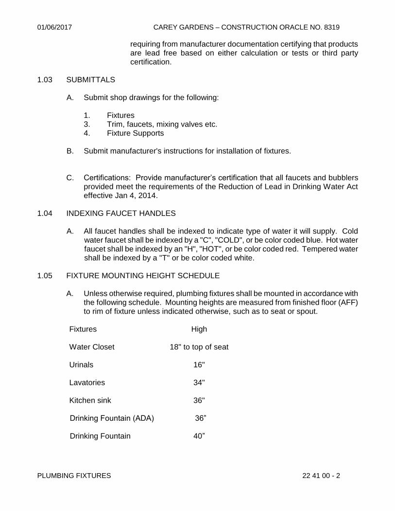
01/06/2017 CAREY GARDENS – CONSTRUCTION ORACLE NO. 8319
PLUMBING FIXTURES 22 41 00 - 2
requiring from manufacturer documentation certifying that products are lead free based on either calculation or tests or third party certification.
1.03 SUBMITTALS
A. Submit shop drawings for the following:
1. Fixtures 3. Trim, faucets, mixing valves etc. 4. Fixture Supports
B. Submit manufacturer's instructions for installation of fixtures.
C. Certifications: Provide manufacturer’s certification that all faucets and bubblers
provided meet the requirements of the Reduction of Lead in Drinking Water Act effective Jan 4, 2014.
1.04 INDEXING FAUCET HANDLES
A. All faucet handles shall be indexed to indicate type of water it will supply. Cold water faucet shall be indexed by a "C", "COLD", or be color coded blue. Hot water faucet shall be indexed by an "H", "HOT", or be color coded red. Tempered water shall be indexed by a "T" or be color coded white.
1.05 FIXTURE MOUNTING HEIGHT SCHEDULE
A. Unless otherwise required, plumbing fixtures shall be mounted in accordance with the following schedule. Mounting heights are measured from finished floor (AFF) to rim of fixture unless indicated otherwise, such as to seat or spout.
Fixtures High
Water Closet 18" to top of seat
Urinals 16"
Lavatories 34" Kitchen sink 36"
Drinking Fountain (ADA) 36” Drinking Fountain 40”

01/06/2017 CAREY GARDENS – CONSTRUCTION ORACLE NO. 8319
PLUMBING FIXTURES 22 41 00 - 3
PART 2 – PRODUCTS 2.01 FIXTURE SUPPORTS
A. Water closet chair carrier shall be J. R. Smith, Josam Co., Zurn, Watts Drainage, MIFAB or Tyler Pipe/Wade Division having two separate base supports secured to an adjustable face plate. Carrier shall include cast iron anchor foot assembly, cast iron fittings, cast-iron adjustable faceplate with side mounted base support assembly, cast iron nipple and cast iron coupling. Chair carrier with masonry wall construction for above floor soil piping shall be: J. R. Smith 210-M51-M54 or 210Y-M51-M54, Zurn Z1203-CC, MIFAB MC-10-3-CI-G, Watts Drainage Products ISCA-101-L/R-CI and Wade 310-M26 for single fixture; J. R. Smith 210D or 210DY, Zurn Z1203D-CC, MIFAB MC-10D-CI-G or Wade 310D-M26 or Watts Drainage Products ISCA-101-D-CI for back to back fixtures; J. R. Smith 240-M5l or 240Y-M51, Zurn Z1204-1N4-CC, MIFAB MC-13-3-CI-G and Wade 340-M26 or Watts Drainage Products ISCA-131-L/R-CI for a single fixture roughing tying into a stack with single side inlet; J. R. Smith 240D or 240DY, Zurn Z1204-1ND4-CC, MIFAB MC-13D-CI-G and Wade 340D-M26 or Watts Drainage Products ISCA-131-D-CI for back to back fixtures; J. R. Smith 280-M51, Zurn Z1204-2N4-CC, MIFAB MC-13-CI-HS-3-G and Wade 340A-M26 or Watts Drainage Products ISCA-131-2-CI for a single fixture roughing tying into a stack with double side inlets; J. R. Smith 280-D, Zurn Z1204-2ND4-CC MIFAB MC-13D-CI-G and Wade 340A-M26 or Watts Drainage Products ISCA-131-D2-CI for back to back fixtures.
Chair carrier for fixtures installed in a stud wall construction and connecting to a
stack with adjustable steel or cast iron face plate shall be: J. R. Smith 0550F, MIFAB MC-13-CI-G and Wade 371-M26 or Watts Drainage Products ISCA-151-D-CI for single fixture; J. R. Smith 0550F-D, MIFAB MC-13D-CI-HS-G and Wade 371D-M26 or Watts Drainage Products ISCA-151-D-CI for back to back fixtures. Carrier for a single fixture roughing and connecting to a branch pipe shall be: J. R. Smith 542, MIFAB MC-13-CI-HS-G and Wade 350-NH-M26 or Watts Drainage Products ISCA-141-4-V2-CI.
B. Chair carrier for barrier-free water closets whose seat is set more than 16” above
the floor shall be JR Smith “Hi-Set” elevated adjustable fixture support, Zurn, Josam Co., MIFAB or Tyler Pipe/Wade Division. Carrier shall include an anchor foot assembly, cast iron nipple and cast iron coupling. Chair carrier on masonry wall construction for above floor soil piping shall be: J. R. Smith 115-M51 or 115Y-M51, MIFAB MC-10-3-CI-G and Wade 310H–M26 or Watts Drainage Products ISCA-101-L/R-CI for single fixture; J. R. Smith 115D or 115DY, MIFAB MC-10D-CI-G and Wade 310H-D-M26 or Watts DRAINAGE Products ISCA-101-D-CI for back to back fixtures; J. R. Smith 175-M51 or 175Y-M51, MIFAB MC-13-3-CI-G and Wade 340H-M26 or Watts Drainage Products ISCA-131-L/R-CI for a single fixture roughing tying into a stack with single side inlet ; J. R. Smith 175D or 175DY, MIFAB MC-13D-CI-G and Wade 340H-D-M26 or Watts Drainage Products ISCA-131-D-CI for back to back fixtures; J. R. Smith 185-M51 or 185Y-M51, MIFAB MC-13-2-CI-G and Wade 340A-H-M26 or Watts Drainage Products ISC-
01/06/2017 CAREY GARDENS – CONSTRUCTION ORACLE NO. 8319
PLUMBING FIXTURES 22 41 00 - 4
131-2-CI for a single fixture roughing tying into a stack with double side inlets; J. R. Smith 185D or 185DY, MIFAB MC-13D-2-CI-G and Wade 340A-H-D-M26 or Watts Drainage Products ISC-131-D2-CI for back to back fixtures.
1. Fixture support for wall-mounted, barrier–free water closets that have a final
installation height of 14” to the rim of the fixture shall be adjustable type with the center line of the discharge outlet set at 4” minimum. Base section of the support shall be securely anchored to the floor and support for a single water closet shall come with a rear lug for anchoring to the floor. Acceptable fixture support shall be JR Smith, model #0211 series; Zurn, model #Z1201 series, ISCA-101-L/R-CI or other approved equal.
C. Each carrier shall be provided with the appropriate fixture supporting devices
specified, or recommended by the manufacturers.
D. Urinal support: Floor mounted carrier support shall be high strength steel uprights with welded feet, top support and bottom bearing plates, both adjustable and mounting fasteners Carrier must be similar to: Josam Co 17560-UR, Zurn Z1222, MIFAB MC-32, Wade 400-AM11-M36, Watts Drainage Products CA-321 or Jay R. Smith. All standard urinals and barrier-free fixtures from Kholer shall be supported by Jay R. Smith Figure 637-M31; barrier free units from American Standard: Jay R. Smith Figure 644-M31 and all units from Crane: by Jay R. Smith Figure 637M-M31.
E. Lavatory/Hand Sinks support: floor-mounted, concealed arms with positive
mechanical locking device, arms fully adjustable, high-strength steel uprights with welded feet and supporting brackets: Josam Co. 17100, MIFAB MC-42, Zurn Z1231, Wade 520-M36, Watts Drainage Products TCA-411 or Jay R. Smith Figure 700-M31.
F. Service Sink: floor-mounted fixture support with acid resistant coating, exposed
arms and a fixture mounting plate to receive the fixture manufacturer’s hanger device, high-strength steel uprights with welded feet and supporting brackets. Carrier shall be similar to J. R. Smith Figure 851-M31, Watts Drainage Products ISCA-560 and Wade 640-M36.
2.02 FLUSH VALVES
A. Valves for water closets and urinals shall be of the exposed type.
B. Water Closet: Valve shall be high efficiency type, using 1.28 gallon flush (1.28 gpf). Flushometer shall be a polished brass chrome plated assembly including a lever handle requiring no greater than 5 lbs force. Flush valve shall be similar to Zurn Z6000PL-HET-YO, Sloan Model 111-1.28, Delta Commercial Model #81T201-48 or Delany F402-1.28-T6-T42. Contractor needs to verify flow requirements with the manufacturer of the selected flushometer as the valve may not work with certain toilet bowls.

01/06/2017 CAREY GARDENS – CONSTRUCTION ORACLE NO. 8319
PLUMBING FIXTURES 22 41 00 - 5
D. Urinals: Flush valve shall use 0.125 (1/8) gallon/flush with 3/4" top spud, chrome
plated, screwdriver stop with cap, lever handle requiring no greater than 5 lbs force for the valve’s operation. Other valve accessories shall include spud and wall escutcheons, vacuum breaker and adjustable tailpiece. Valve shall be similar to Sloan Model 186-0.125, Zurn Z6003PL-ULF, Delany F451-.125 T6 T42 or Delta Commercial #81T231-05. Contractor should note that listed valves may not work with certain urinals; verify with valve manufacturer for compatibility and flow requirements with the selected flushometer.
2.03 STOPS
A. Provide angle stop stop with each compression type faucet whether specifically called for or not. Provide angle stops by Kohler K-7675CP, McGuire HST06LKSB, Chicago 442-LK, T&S Brass and Bronze Works B-0418CP, EBC (Engineered Brass Company) VAH15BK or Zurn Aquaspec Z8802LRLKC1-PC; cast brass 1/2" IPS straight by Kohler K-7679, Chicago 45-LK, EBC VSH15BK, T&S Brass and Bronze Works B-0416CP or Zurn Z8841LRLKC1-PC.
C. Supply from stops shall be chrome plated copper flexible tubing.
D. Supply pipe from wall to valve stop shall be rigid threaded IPS copper alloy pipe. 2.04 FAUCET
A. All faucets shall meet the requirements of the federally mandated “Reduction of Lead in Drinking Water Act”. Regardless of model numbers indicated herein, provide equivalent models that meet the requirements of the act.
B. Coordinate faucet inlets with supplies and fixture holes and outlet with spout and
fixture receptor for lavatories and sink. Coordinate faucet inlets with supplies and outlet with diverter valve for bathtubs and showers.
D. All Lavatories: Single Lavatory, Multiple Lavatories, shall have a faucet deck
mounted 4" center having the following features: metering type valves: 0.125 gallon/cycle (.125gpc) factory set and with a vandal resistant spray outlet. Faucet shall be chrome plated heavy cast brass construction. Each lavatory shall be fitted with grid drain: Kohler, K-7129-A-CP, Moen 14750, Zurn Z8743-PC, Mcguire 155AECO, T&S Brass and Bronze Works B-0899 or American Standard 2411.015. Faucet shall be Speakman 4141-NYC-BOCA/FLO-LD with brass yoke assembly, Chicago Faucets 802-VE2805-665CP, T&S Brass and Bronze Works B-0831-PA with B-0199-08F-05, Zurn Aquaspec Z86500-3M, Moen 8886-52602-NYCSCA with 0.125 gallon/cycle metering valve and vandal resistant spray outlet, Component Hardware Group (CHG) KN83-4204-CA9, Delta Faucet 86T1153 or American Standard 1340.225.002 with 066508-0020A.

01/06/2017 CAREY GARDENS – CONSTRUCTION ORACLE NO. 8319
PLUMBING FIXTURES 22 41 00 - 6
2.05 WATER CLOSETS (P-1)
A. Water closets shall be approved vitreous china. Water closets shall be floor mounted. Refer to drawings for plumbing fixture schedule.
2.06 WALL HUNG URINAL, TOP SPUD (P-3)
A. Urinal shall be wall hung, 3/4" top spud, siphon jet or washout, 0.125 (1/8) gallons per flush, vitreous china. Urinal shall be American Standard 6590.1250.125gpf, Crane Plumbing 7399.125, Kohler K-4904-ET, Mansfield #422., Sloan Model SU-1000-0.125, Zurn Z5798.207.00. Contractor needs to exercise care when ordering flush valve as some urinals may not work with the flushometers listed in Article 2.02.
2.07 SINGLE LAVATORY (P-2)
A. Lavatory shall be 22" x 21", vitreous china, with 4” center faucet holes Provide with holes for concealed arm carrier systems. Color: white.
C. Lavatory drain shall be the integral perforated grid type with cast brass locknut,
1¼" diameter tailpiece, and chrome plated finish: Kohler K-7715-CP, Eljer 803-0552, Chicago 327A, EBC SG7, Zurn Z8743-PC, McGuire 155AECO or T&S Brass and Bronze Works, Inc. B0899.
D. Lavatory trap shall meet New York City Building Code requirements, chrome
plated cast brass with cleanout plug and cast brass slip nut: 1¼" inlet x 1½” outlet by Eljer 804-1125, McGuire 201C, Kohler K-9009-CP, EBC TN140 or Zurn Z8716B-PC.
E. Hot and cold water supply piping shall be chrome plated screw brass piping with
1/2" IPS angle stops. 2.08 KITCHEN SINK (P-4)
A. Kitchen sink shall be double bowl sink for mounting in a counter top. Bowl shall be 18-gage, type 302 or 304 stainless steel with mounting channels welded to the rim. Rear ledge shall have openings for a deck mounted single lever faucet. Sink bowl 9" deep with opening for drain outlet centered within the bowl. The underside of bowl shall be coated with a moisture and fireproof sound deadening material. Sink shall be provided with a sufficient number of U-channel or J-channel clips so that the spacing between clamps is no greater than 11". Sink shall be Elkay LR-33225 or equal

01/06/2017 CAREY GARDENS – CONSTRUCTION ORACLE NO. 8319
PLUMBING FIXTURES 22 41 00 - 7
B. Unit shall be fitted with one (1) chrome plated brass deck mounted single lever faucet having at least 87/16" swing spout with 0.5 gpm vandal resistant spray outlet. American Standard Reliant model 4205.001 or equal.
C. Provide a sink strainer for each bowl; strainer shall be type 304 stainless steel to fit
3½” bowl opening with 1½” tailpiece Elkay LK-18B, Just J-35SSF or equal.
E. Stop valve where shown on Drawing shall be 1/2” angle type Chrome plated brass loose key 1/2" IPS by Kohler K-7675CP, McGuire HST06LKSB, Chicago 442-LK or equal.
F. Hot and cold water supply piping shall be chrome plated screw brass piping with
1/2" IPS angle stops 2.09 DRINKING FOUNTAIN(P-5)
A. Single bubbler wall mounted drinking fountain with bottle filling station shall be designed to meet the clearances required by ANSI A117.1 and ADA. Fountain shall be made from type 300 stainless steel with a satin finish. All seams shall be welded and ground smooth. Unit shall have stainless steel basin with anti-splash ridge and removable drain strainer. All waterways shall be constructed of copper. Unit shall be furnished with a bottom plate secured with vandal resistant screws. Furnish a screwdriver for removing bottom plate screws. Bubbler shall be chrome plated with non-removable anti-squirt feature and integral hood. Automatic stream height regulator shall be located inside unit to prevent tampering. Includes self-closing, light touch front and side pushbar actuation. Unit shall include filter certified to NSF/ANSI for lead reduction with visual monitor to indicate when replacement is necessary.
Bottle Filler shall be sensor-actuated with auto shut-off timer and bottle counter, shall provide 1.1 to 1.5 GPM with laminar flow for minimal splash and shall include anti-microbial protected plastic components. Unit shall be lead-free design which meets Safe Drinking Water Act and is certified to NSF/ANSI 61. Unit shall be Halsey Taylor HTHB-HACD, Elkay LMABFDWSSK or Acorn Aqua All1400B-VRB-BF2S-WF1 modified with copper tubing. All bubblers shall meet the requirements of the federally mandated “Reduction of Lead in Drinking Water Act”. Regardless of model numbers indicated herein, provide equivalent models that meet the requirements of the act.
B. Provide Josam Co., J. R. Smith Figure 824-M31 or Wade 420-M36 floor mounted
chair carrier. Floor mounted hanger plate carrier using rectangular high-strength steel uprights welded to base plates.
C. Drinking fountain trap shall meet New York City Building Code requirements, shall
be chrome plated cast brass: 1¼” inlet by 1½” outlet by Eljer 804-1125, McGuire 201C, EBC TN140, Kohler K-8995-CP or Zurn Z8716B-PC.
D. Cold water stop shall be chrome plated cast brass 1/2" IPS angle stop as specified
in the Stops Article.

01/06/2017 CAREY GARDENS – CONSTRUCTION ORACLE NO. 8319
PLUMBING FIXTURES 22 41 00 - 8
2.10 SHOWER, INDIVIDUAL, NON-BARRIER-FREE
A. Non-barrier-free individual shower shall be a corner mounted or surface mounted shower module consisting of shower head, thermostatic shower valve, metering valve, and built-in liquid soap system. Module housing and piping shrouds shall be made from 16-gage stainless steel, type 304 with a satin finish. All internal water piping shall be copper tubing. Shower head shall be solid brass triple chrome plated with adjustment of spray from coarse to fine mist spray. Shower head shall have low flow control which maintains 1.8GPM at pressures from 10-100 PSI and up-down ball joint. Shower valve shall regulate shower water to maintain a constant water temperature and shall shut shower water off in the event of loss of either water supply. A metering valve shall be installed between the shower valve and the shower head. Metering valve shall be adjustable to deliver water between 5 to 60 seconds. Soap dispenser valve shall be designed for liquid soap from a built-in liquid soap system. Soap valve shall be constructed of solid brass with stainless steel spring and metering system, and Buna-N O-ring seals. Entire exterior of soap valve shall be chrome plated. Soap dispenser valve shall be the equal of Acorn 3050.
B. Built-In Liquid Soap System: Integral soap tank, factory pre-piped, and installed
within the Shower. The liquid soap shall be piped to the dispenser. Shower single station model shall be provided with a one quart tank. Soap dispenser shall be supplied for each soap station. The exact size is affected by shower supply configuration.
C. Shower modules shall be Acorn "Apex" Model #M0428-E503 APEX SHOWER
MODIFIED w/F1.6-Z-BS-MV; Willoughby Industries CWKS-/TSV-PM1-1.8GPMUDBJ-GX-PS-LSD-MOD or Bradley WS-1K-TMV-AST-LBJ-1.8GPMG-CS for corner mounted. For surface mounted shower, use Acorn "Apex" Model #M0458-E503 APEX SHOWER MODIFIED w/F1.6-Z-BS-MV; Willoughby Industries CWSMS-TSV-PM1-1.8GPMUDBJ-GX-PS-LSD-MOD or Bradley WS-1WCA-ADA-TMV-AST-LBJ-1.8GPMG-CS-SHV.
D. Provide thermostatic mixing valve to ensure that safe tempered water is delivered
to the bather. Mixing valve shall be similar to Acorn model #SV16, Powers LFe420 or other approved equal. Valve shall comply with ASSE 1016.
2.11 SHOWER, INDIVIDUAL, BARRIER-FREE (SURFACE-MOUNTED)
A. Barrier-free individual shower shall be a surface mounted shower module consisting of shower head, hand-held shower, thermostatic shower valve, diverter, surface mounted soap dish. Module housing and piping shroud shall be made from 16-gage, type 304 stainless steel with a satin finish. All internal water piping shall be copper tubing. Shower head shall be solid brass triple chrome plated with adjustable spray from course to fine mist. Shower head shall have low flow control which maintains 1.8 GPM at pressures from 10 to 100 PSI and up-down ball joint. Hand-held shower shall have a 5' spiral stainless steel hose, vacuum breaker,

01/06/2017 CAREY GARDENS – CONSTRUCTION ORACLE NO. 8319
PLUMBING FIXTURES 22 41 00 - 9
white plastic hand shower and bracket. Shower valve shall regulate shower water to maintain a constant water temperature, shall have a limit stop to prevent discharge of shower water to no higher than 105°F, and shall shut shower water off in the event of loss of either water supply. A lever handle diverter shall be used to deliver water to hand-held shower or shower head. A barrier-free fold-up padded seat shall be Acorn 1103-31 (Left Hand) and 1103-32 (Right Hand) or Willoughby Industries FSS-R (Right Hand Seat), FSS-L (Left Hand Seat).
B. Shower module shall be Acorn "Apex" Model Number #M0458-E559-3 APEX
SHOWER MODIFIED w/F1.6-Z-QD; Willoughby Industries CWBFS-250-TSV-PM1-1.8GPMUDBJ-GX-PS-FSS-L/R or Bradley WS-1WCA-ADA-TMV-AST-LBJ-1.8GPMG-SHV.
C. Provide thermostatic mixing valve to ensure that safe tempered water is delivered
to the bather. Mixing valve shall be similar to Acorn model #SV16, Powers LFe420 or other approved equal. Valve shall comply with ASSE 1016.
1. For Multi [Gang] showers, provide mixing valve installed at the point of use
that complies with ASSE 1069. Mixing valve shall be similar to Acorn model #ST7069, Powers model #LM495-2-A; LM 496-2-A or other approved equal.
2.12 SHOWER, INDIVIDUAL, BARRIER-FREE (FLUSH-MOUNTED)
A. Barrier-free individual shower shall be a flush or recessed mounted shower module consisting of shower head, hand-held shower, thermostatic shower valve, diverter, recessed soap dish. Module housing and piping shroud shall be made from 16-gage, type 304 stainless steel with a satin finish. All internal water piping shall be copper tubing. Shower head shall be solid brass triple chrome plated with adjustable spray from course to fine mist. Shower head shall have flow control which maintains 1.8GPM at pressures from 10 to 100 PSI and up-down ball joint. Hand-held shower shall have a 5' spiral stainless steel hose, vacuum breaker, white plastic hand shower and bracket. Shower valve shall regulate shower water to maintain a constant water temperature, shall have a limit stop to prevent discharge of shower water to no higher than 105°F, and shall shut shower water off in the event of loss of either water supply. A lever handle diverter shall be used to deliver water to hand-held shower or shower head. A barrier-free fold-up padded seat shall be Acorn 1103-31 (Left Hand) and 1103-32 (Right Hand), or Willoughby Industries FSS-R (Right Hand Seat), FSS-L (Left Hand Seat).
B. Shower module shall be Acorn "Apex" Model #M0418-E559-3 APEX SHOWER
MODIFIED w/F1.6-Z-QD-D; or Willoughby Industries CWBFS-200-TSV-PM1-1.8GPMUDBJ-GX-FSS-L/R.
C. Provide thermostatic mixing valve to ensure that safe tempered water is delivered
to the bather. Mixing valve shall be similar to Acorn model #SV16, Powers LFe420 or other approved equal. Valve shall comply with ASSE 1016.

01/06/2017 CAREY GARDENS – CONSTRUCTION ORACLE NO. 8319
PLUMBING FIXTURES 22 41 00 - 10
1. For Multi [Gang] showers, provide mixing valve installed at the point of use that complies with ASSE 1069. Mixing valve shall be similar to Acorn model #ST7069, Powers, model #LM495-2-A; LM 496-2-A or other approved equal.
PART 3 – EXECUTION 3.01 COMMISSIONING OF PLUMBING FIXTURES
A. Plumbing Contractor shall comply with the Commissioning Requirements of Contract
B. All domestic water piping testing and sterilization, drainage and vent piping testing,
and plumbing fixtures installation shall be completed prior to commencement of the commissioning process.
3.02 CHAIR CARRIERS
A. Chair carrier feet and anchor foot, where provided, shall be securely fastened to the structural slab, utilizing all support openings provided, with anchor bolts and shields.
B. Chair carrier for water closets shall be connected to soil and vent piping as shown
on Drawing. 3.02 SEALING
A. Seal between fixture and wall and/or fixture and floor with silicone sealant. 3.03 FIXTURE HEIGHT
A. Fixtures shall be installed at height as shown on Drawings and/or as specified in Fixture Mounting Heights Schedule.
3.04 FIXTURE INSTALLATION
A. Fixtures shall be installed in accordance with manufacturer’s installation instructions. Fixtures shall have their rim and backsplash set level.
B. Unless otherwise specified or indicated on the Drawings, wall hung water closets
shall be siphon jet type. 3.05 WALL HUNG WATER CLOSET
A. Install water closet chair carrier.
01/06/2017 CAREY GARDENS – CONSTRUCTION ORACLE NO. 8319
PLUMBING FIXTURES 22 41 00 - 11
B. Install the exposed flushometer valve and wall plate as per manufacturer’s instructions for accessible water closets with handle mounted on wide side of compartment. Connect flush valve to cold water supply and water closet.
C. Seal between water closet and wall.
3.06 BARRIER-FREE WATER CLOSET
A. Barrier-Free water closet shall be installed in accordance with Par. 3.05 for wall hung water closet. Install the fixture chair carrier specified in Article 2.01 Par. B.
B. Barrier-Free water closet shall be set at the specified height.
3.07 WALL HUNG URINALS (BARRIER-FREE AND NON-BARRIER-FREE)
A. Install urinal support as per manufacturer’s instructions. B. Install flushometer valve for accessible urinals with handle mounted on wide side
of compartment. Connect flush valve to cold water supply and urinal.
C. Seal between urinal and wall. 3.08 BARRIER-FREE URINAL
A. Barrier-free urinal shall be installed in accordance with Par. 3.07 for wall hung except that the height shall be 17” from finished floor to rim.
3.09 LAVATORIES, CHINA
A. Install new chair carrier.
B. Install faucet or faucets and drain including tailpiece on lavatory.
C. Install stop valves on hot and cold water supplies and trap on fixture waste.
D. Install lavatory on chair carrier and connect tailpiece to trap. Also connect hot and cold water stops to faucet or faucets. Fasten thermostatic mixing valve to the wall and connect the hot & cold water supplies. Connect outlet of the thermostatic valve to the hot water connection of the faucet.
3.10 LAVATORIES, CHINA BARRIER-FREE
A. Install new chair carrier
B. Install faucet on lavatory.
C. Install trap on fixture waste and connect to tailpiece.
01/06/2017 CAREY GARDENS – CONSTRUCTION ORACLE NO. 8319
PLUMBING FIXTURES 22 41 00 - 12
D. Connect hot and cold water supplies to faucet. Fasten thermostatic mixing valve to the wall and connect the hot & cold water supplies. Connect outlet of the thermostatic valve to the hot water connection of the faucet.
3.11 DRINKING FOUNTAINS-WALL MOUNTED
A. Install chair carrier
B. Install drain with tailpiece on receptor.
C. Secure fixture to chair carrier
D. Install trap on fixture waste and connect to tailpiece.
E. Install stop valve on cold water supply and connect to unit metering valve.
F. Install bottom plate on unit. 3.12 BUILT-IN SHOWER
A. Install trap on fixture waste. Connect shower drain to trap. Adjust strainer to required elevation. Install flashing and clamp membrane and flashing to drain.
B. Install shower module to wall and connect to hot and cold water supplies. Fasten
thermostatic mixing valve to the wall and connect the hot & cold water supplies.
C. Barrier-free shower, install grab bar and fold-up seat.
D. Install shower curtain and curtain rod. 3.13 SERVICE SINKS
A. Install chair carrier.
B. Install trap on fixture waste.
C. Mount drain on sink.
D. Install sink on chair carrier and connect drain to trap.
E. Install hot and cold bibs on respective hot and cold water supplies on SS-1 and SS-2.
F. Install combination faucet on backsplash and connect to hot and cold water
supplies SS-3.
END OF SECTION

01/06/2017 CAREY GARDENS – CONSTRUCTION ORACLE NO. 8319
SECTION 22 63 13 - GAS PIPING SYSTEM PART 1 - GENERAL 1.01 DESCRIPTION OF WORK
A. Extent of gas piping system work is indicated on Drawings and by the requirements of this Section.
1.02 SUBMITTALS
A. Submit Shop Drawings indicating all operating pressures and catalog cuts for the following:
1. Gas piping materials
2. Gas piping layout including service, meter and distribution piping
3. Gas Safety Shut-Off Valves
5. Gas Lubricated Plug Valves and Gas Cocks
7. Strainers 8. Pipe joint sealing materials 9. Flanges and Gaskets 10. Pulsating Gas Meter 11. Relay & Control Panel
12. Gas Pressure Regulators
B. Submit copies of Certified Welder Qualifications. Submittal shall be made no less
than seven (7) working days prior to commencement of work. C. “New Steel Gas Pipe Corrosion Record” affidavit issued by Con Edison to
document acceptance of the installed cathodic protection system.
D. Submit copies of the detailed procedure specification to be used for production welding in accordance with API 1104 Sample Procedure Specification Form.
E. Submit a detailed schedule for the installation of gas piping and the welding
thereof.
GAS PIPING SYSTEM 22 63 13 - 1

01/06/2017 CAREY GARDENS – CONSTRUCTION ORACLE NO. 8319
F. Certificate of satisfactory installation from the manufacturer of gas boosting system.
1.03 QUALITY ASSURANCE
A. Comply with the rules and regulations of the Gas Company, New York City Building Department and with the latest regulations of the Administrative Code of the City of New York.
B. When welding is to be performed as part of the work covered in this specification,
the Contractor, before assigning any welder for this work, shall provide the Authority with the names of welders to be employed for this work. Welders installing gas piping at any pressure shall be qualified for all pipe sizes, wall thicknesses, and all positions in accordance with the latest editions of either API 1104 or ASME Section IX Boiler and Pressure Vessel Code and be re-qualified on an annual basis. The qualification testing shall be performed by an agency listed with the Department of Buildings, and the inspector, that verifies the welder’s qualifications, shall have a minimum radiography qualification of Level II in accordance with the American Society of Non-Destructive Testing Recommended Practice Document No. SNT-TC-IA, Supplement A. Copies of the certified welder qualification reports shall be maintained by the responsible welding contractor and shall be submitted to the Authority.
C. All welding of gas piping shall be in full compliance with the latest editions of API 1104 and ASME Section IX Boiler and Pressure Vessel Code. Whenever welding operations are performed, the services of a full time certified inspector or certified technician shall be retained by the Authority to ensure said compliance. Certified inspectors and certified technicians shall be qualified to perform visual inspections and shall have a minimum radiography qualification of Level II in accordance with the American Society of Non-Destructive Testing Recommended Practice Document No. SNT-TC-IA, Supplement A. The certified inspector or certified technician shall also be responsible for Controlled Inspection sign off upon completion of the work.
E. The Project Officer shall coordinate with FID to assure compliance during all
phases of the work. PART 2 - PRODUCTS 2.01 MATERIALS A. GENERAL
1. GAS SERVICE & GAS METER(S) : As per Utility Co. Requirements
GAS PIPING SYSTEM 22 63 13 - 2

01/06/2017 CAREY GARDENS – CONSTRUCTION ORACLE NO. 8319
2. Gas Distribution Piping
a. Gas distribution piping shall be in accordance with Chapter 4 – Gas Piping Installations of the 2014 NYC Fuel Gas Code
b. Gas distribution piping located on the roof or exposed to the
elements shall receive one coat of rust inhibitor paint and one coat of yellow finish paint.
B. Piping
1. Gas piping shall be standard weight (Schedule 40) black steel pipe. Gas control, vent and relief piping shall also be standard weight, schedule 40 black steel pipe. Steel pipe shall be seamless or welded made in accordance with the Current Edition of the ASTM A53 Specification.
2. In no case shall any gas pipe be less than 3/4". The sizes of pipe indicate
nominal pipe size.
C. Gas Distribution Pipe Joints (Based on Gas Pressure in Serving Utility Piping Network)
1. Gas pressure in the utility’s street piping network is 1/2 psig (14” w.c.) or
less:
a. 4”(inches) pipe dia. and smaller . Threaded or welded b. Over 4” (inches) pipe dia. . . . . Welded
2. Gas pressure in the utility’s street piping network is greater than 1/2 psig
but less that 15 psig (inclusive of the utility company providing a service regulator to reduce the incoming pressure to 1/2 psig):
a. Under 3” (inches) pipe dia. . . .Threaded or Welded
b. 3”(inches) and larger pipe dia. . Welded 3. Piping over 15 psig a. All piping . . . . . . . . . . . . Welded
D. Fittings
1. Fittings for screwed gas piping shall be 150 lb, class 150, black malleable iron fittings, conforming to ASTM A197, latest edition.
2. Compression type fittings and steel welding fittings shall be as specified
and approved by the Gas Company.
GAS PIPING SYSTEM 22 63 13 - 3

01/06/2017 CAREY GARDENS – CONSTRUCTION ORACLE NO. 8319
3. Steel butt welding fittings shall conform to ANSI B16.9 requirements.
E. Flanges
1. All flanges shall be steel and compatible in type and pressure ratings with mating flange and shall comply with ANSI B16.5.
2. Flanges shall be welding neck or threaded end. Slip on flanges are not
permitted.
3. Where 150 pound steel flanges are bolted to Class 125 cast iron flanges, the raised face on the steel flange shall be removed.
F. Gaskets
1. Gaskets shall be compatible with the gas service on which they are used,
without change to their chemical or physical properties.
2. Gasket shall be BLUE-GARD compressed asbestos free gaskets, style 3000 or GYLON gasketing style 3500, color: Fawn with Blue brand both as manufactured by Garlock Inc.
3. Gaskets of metal or metal-jackets, aluminum o-rings and spiral wound
metal gaskets, or other materials, if approved by the Utility Company may be used.
4. Full face gaskets shall be used with all bronze and cast iron flanges.
G. Bolts and Nuts
Bolts and nuts shall be of best quality bolt steel with square head bolts and hexagon nuts with machine cut V-threads.
H. Thread joint sealant materials
Thread sealant to be used on natural gas piping shall be RectorSeal Corp No. 5, Oatey Great Blue pipe joint compound Hercules Megaloc Multi-purpose thread sealant or approved equal. Thread sealant shall be a non-toxic, soft setting, slow drying sealant made from inert fillers. The joint sealant material may contain Teflon, if that substance is the approved type for natural gas application. Approved Teflon tapes may be used on natural gas lines. Non-approved Teflon tapes for use on piping for a natural gas system are prone to tearing when pipes are being assembled and tightened and bits of torn tape can migrate into the fluid system, clogging valves, screens, and filters.
2.02 GAS SAFETY SHUT-OFF VALVES
GAS PIPING SYSTEM 22 63 13 - 4

01/06/2017 CAREY GARDENS – CONSTRUCTION ORACLE NO. 8319
A. Gas safety shut-off valves shall be FM & UL listed, electric motor operated, normally closed, manual reset type with standard handle. Valves shall be rising stem design with a straight through flow path with metal-to-metal seat and disc arrangement. The valve seat and rising stem shall be stainless steel and the disc ductile iron. Valve body shall be cast iron. Valves shall be provided with a NEMA 4 enclosure modified for Class 1, Division II hazardous locations, Solenoid voltage: 115VAC 60 Hz. Valves shall meet ANSI Class VI leakage standard and shall be provided with a visual indicator to note the position of the valve whether "OPEN" or "SHUT".
B. Gas safety shut-off valves 2" and smaller shall be threaded, 2½" and larger shall
be flanged. Flanged valves shall be provided with companion flange set by valve manufacturer.
C. Gas safety shut-off valves shall be Maxon Corporation Series SMM12 for sizes 2"
and smaller and Series CMM12 for valves 2½" and larger. All valves shall be provided with trim package 1-1.
D. A gas safety shut-off valve fitted in gas supply lines to water heaters and other
gas-burning equipments shall be provided. Gas safety shut-off valve for equipment operating on natural gas shall be interlocked with a remote control switch/break glass switch that is intended to stop the flow of natural gas to these equipments. This contractor shall coordinate with the electrical contractor for the installation of the gas safety valve and interlocking same with the break glass switch.
2.03 GAS SAFETY SHUT-OFF VALVES; OPERATING SIGN
A. Provide a sign made of two colors laminated engravers stock phenolic, 1/16" minimum thickness, machine engraved to expose inner core color (white). Signs to be provided with uniform margins and character size minimum 1/4" high.
B. Sign to read:
"IMPORTANT"
GAS SAFETY SHUT-OFF VALVES LOCATED IN THE NEAR-GAS-METER PIPING MUST BE MANUALLY RESET UPON ACTION OF THE GAS LEAK DETECTION SYSTEM OR LOSS OF NORMAL ELECTRICAL POWER.
2.04 GAS LUBRICATED PLUG VALVES
A. Lubricated plug valves for use on gas service and gas meter piping shall be as approved by the Gas Company.
B. Lubricated plug valves for use on gas distribution piping; mains, branches and
base of risers shall be cast iron body, rated for 200 pounds cold working pressure and shall be wrench operated, except valves 10" and larger which shall be worm gear operated.
GAS PIPING SYSTEM 22 63 13 - 5

01/06/2017 CAREY GARDENS – CONSTRUCTION ORACLE NO. 8319
C. Lubricated plug valves 2" and smaller shall be short pattern threaded; 2½" and larger shall be regular pattern flanged.
D. Lubricated plug valves shall be Nordstrom Valves Inc. Fig. 142 for sizes 2" and
smaller, Fig. 115 for sizes 2½" through 4" inclusive, Fig. 165 for sizes 6" and 8", and Fig. 169 for sizes 10" and larger; or Walworth Fig. 1796 for sizes 2" and smaller, Fig. 1700F for sizes 2½" through 8", and Fig. 1707F for sizes 10" and larger.
2.05 GAS COCKS
A. Gas cocks shall be for use only as manual gas shut-off valves at each piece of gas burning equipment; shall be of the plug type, bronze construction with check, nut and washer bottom and tee handle.
B. Gas cocks shall be Fig. 10596 as manufactured by A. Y. Mc Donald Mfg. Co., or
Series 52 as manufactured by Conbraco Industries Inc.
C. Gas cocks shall only be used on piping 1" and smaller.
2.06 GAS METER
A. Secure from the utility company gas meter and other ancillaries such as gas
regulator that may be necessary for the complete installation of the gas system.
For projects involving LonWorks network, the contractor shall request pulsating type gas meter, capable of transmitting signal outputs to the energy management system (part of the BMS) that is provided by the Temperature Control Contractor, TCC. Pulsating gas meter shall come equipped with dry contacts (2 wire Form A, single channel; 3 wire Form C, dual channel) that will enable among other things conversion of the pulse signal outputs into therms of natural gas consumed. Coordinate request for the gas meter with the TCC.
2.07 GAS PRESSURE REGULATORS
A. Types 1. Service Pressure Regulator(s): Gas service pressure regulator(s) shall be
as provided by the serving utility company.
2. Line Pressure Regulator(s): Line pressure regulator(s) shall be provided for precise control of the gas pressure and flow rate delivered to gas-burning appliances.
GAS PIPING SYSTEM 22 63 13 - 6

01/06/2017 CAREY GARDENS – CONSTRUCTION ORACLE NO. 8319
a. Regulators shall be installed where line pressure exceeds the gas pressure ratings for appliances supplied thereof and as shown on Drawings.
b. Regulators shall be required to ensure protection for gas-fired
appliances against emergency gas exposure of at least 2 psig. c. Regulators shall comply with ANSI Z21.80 and fabricated with
internal parts that are corrosion–resistant. Regulators shall be capable of maintaining outlet pressure under no flow condition or dead end lock up situation. Approved model # shall be GOVERNOR 2PSIG by Pietro Fiorentini or other approved equal.
B. Venting of Gas Regulators: If located indoors, gas pressure regulators shall have an independent vent pipe routed to the outside of the building. The vent pipe shall be arranged so as to preclude the entry of water or foreign objects. Separate vent piping is not required if the regulator is less than 1¼”, is equipped with and is labeled for utilization with approved vent-limiting device installed as per the manufacturer’s recommendations.
2.15 CATHODIC PROTECTION
A. General Requirements
1. Underground steel gas piping, in addition to being mill-wrapped, shall be cathodically protected for safeguarding against corrosion caused by contact with the ground and as per the requirements of the serving utility company. Cathodic protection is required on both underground service as well as underground distribution gas piping.
2. This contractor shall hire an engineer or a specialist to design the cathodic
protection system. The developed cathodic protection plan shall conform to standards, drawings, rules and regulations established by the serving utility company for pipe corrosion control and cathodic protection.
B. System Components
Cathodic protection intended for underground steel gas piping installation shall include but not be limited to:
1. Coating.
Factory-installed mill wrapped piping needs not be coated unless the wrapping becomes loose or section of the piping or fitting becomes bare during the installation. Apply coating specified by the serving utility company, such as mastic, cold tape or hot coal tar enamel.
GAS PIPING SYSTEM 22 63 13 - 7

01/06/2017 CAREY GARDENS – CONSTRUCTION ORACLE NO. 8319
a. For projects where National Grid is the serving utility, acceptable
coating products are:
1) Polyken Technologies Pipeline Primer # 1027 in conjunction with Polyken Tape # 936 or Polyken Gas UtilityTape or equal. OR
2) Tapecoat Company CT Coldprime in conjunction with
Tapecoat Pipe Tape H-30 or H-50. b. For projects where Con Ed is the serving utility, use:
1) For pipe less than and equal to 4 inches in diameter
a) X-Tru:Bredero Price Co. or Liberty Coating Company b) Pritec: Bredero Price Co. or Liberty Coating Company
2) For pipe sizes 6 inches and larger 1. Pritec: Bredero Price Co. or Liberty Coating Company
2. Insulating Joints
Provide for electrical isolation of underground steel pipe with above-ground steel pipe. Location of insulators shall be guided by criteria imposed by the serving utility.
3. Electrical Continuity
Provide bonding wire, wire connector and thermit weld (aka “cadweld”) for preservation of electrical continuity across couplings, valves and fittings that connect the underground steel pipe.
4. Magnesiun Anodes
Size selection and required number of anodes shall be based upon pipe diameter, length of run and other guidelines enforced by the serving utility company. Magnesium anodes must be provided with # 10 AWG copper wire and be thermite welded to the underground gas pipe. Copper wire must carry black insulation
a. Minimum anode size for pipe within National Grid territory,
irrespective of the size of the pipe diameter and up to 10 feet of pipe run, is 3 pounds.
b. The minimum anode size for pipe within Con Ed territory is 17
pounds.
GAS PIPING SYSTEM 22 63 13 - 8

01/06/2017 CAREY GARDENS – CONSTRUCTION ORACLE NO. 8319
5. Test Stations
Provide at ends of underground pipe runs test stations to monitor the effectiveness of the installed cathodic protection system. Test stations shall be made up by #10 AWG copper wire (white insulation) that is thermite welded to the underground pipe and anode wires (black insulation) that are all spliced inside an easily accessible 4” X 4” electrical box with cover.
6. Pipe Tracer
For safety and to facilitate detection of buried gas piping during future soil excavation, provide pipe tracer. Tape labeled “Warning – Buried Gas Lines Below” shall be placed at a minimum 1 foot on top of the installed piping and it shall be routed the length of the pipe run.
PART 3 - EXECUTION 3.01 GENERAL
A. Make the necessary arrangements with the Utility Company to bring connection to points shown on the Drawings, or as required by the Utility Company and provide the necessary pipe, fittings, valves, service, cocks, governors, etc., to extend these services to the gas system.
B. Exact locations of gas service at property line shall be secured from the Utility
Company by this division and shall be coordinated with electric service location, sewers and water service.
C. As part of the gas service and meter piping certain equipment, such as meters,
regulators, security valves, plug valves, relief valves and compression coupling will be furnished by the Utility Company. However, the Contractor shall provide any additional equipment and materials not furnished by the Utility Company to make this service complete.
D. Gas service shall be extended from the property line into the building. Gas service
line shall pitch toward the building and be provided with drip leg and plugged outlet, or drip pot, as required by the Utility.
3.02 INSTALLATION
A. Gas service and gas distribution piping, number and distribution of appliances, shall be installed as indicated on the Drawings and shall be in accordance with the rules and regulations of the Gas Company and according to the latest regulations
GAS PIPING SYSTEM 22 63 13 - 9

01/06/2017 CAREY GARDENS – CONSTRUCTION ORACLE NO. 8319
of the Administrative Code of the City of New York and shall meet the requirement of the Department of Buildings.
1. Contractor shall arrange for inspection and adjustment of all gas appliances
of the contract, so that they will properly and safely operate with natural gas.
B. The Contractor shall notify the Authority when all is ready for the Gas Company to
extend their service pipe to the street line; and again after tests, when all is in readiness for the installation of the meters. The meters, of the pulsating kind if a LonWorks network is provided, shall then be connected with the service pipes, and with the several lines of distributing pipes. The setting, piping and connecting up of the meters shall be done in accordance with the rules of the Gas Company.
C. Main distributing pipes shall be suspended from the cellar or basement ceilings.
Connections of branches with main shall be made with malleable iron right and left couplings and nipples. Whenever gas lines are unavoidably trapped an accessible drip shall be provided with access door to same.
1. Joint sealing materials (pipe dope) used with screwed (threaded) fitting
shall be applied sparingly and only to the male threads of pipe joints. The burrs made in cutting the pipe shall be removed. Plugged tees in place of elbows shall be used wherever directed. Where pipes of different sizes come together, reducing fittings shall be used. No bushing will be permitted.
2. Piping installed below grade shall be connected by welding by approved
certified welders, or with compression type fittings as specified and approved by the Gas Company.
a. Service piping below grade shall be mill wrapped in accordance with
the Gas Company regulations.
b. Backfill operations shall be started only after welding inspection, coating inspection and testing have been completed as per regulations of the Gas Company.
3. Inter-connections between piping at different pressure levels is not
permitted.
D. Gas meter piping supplying gas to a building shall be provided with regulators to reduce pressures of gas as indicated on drawings.
E. Provide gas lubricated plug valves where specified, shown on Drawings or
otherwise required for control of gas in the distribution piping; mains, branches and at the base of each riser. An accessible manual gas cock or lubricated plug valve of the same size as the pipe shall be installed at each piece of gas burning equipment, to allow for isolation of the equipment and where indicated on
GAS PIPING SYSTEM 22 63 13 - 10

01/06/2017 CAREY GARDENS – CONSTRUCTION ORACLE NO. 8319
Drawings. All valves and cocks for gas throughout the building shall be tagged with numbered metal tags. Install drip, consisting of nipple and cap, at the base of all risers and changes in elevation.
F. GAS VALVES SHALL NOT BE INSTALLED IN CONCEALED LOCATIONS AND
FURNACE PLENUMS. Wall enclosures, pipe spaces or other recess in which gas valves are installed must be vented to an adjoining ventilated area.
G. In no case shall a gas pipe run through a heat/ventilation duct or stairwell. The
Contractor shall do all cutting and boring of holes necessary for extending pipes and branches, making all necessary openings in walls, and shall make all repairs to same.
H. Final connections to burner pilot lights and boiler gas trains shall be made by the
Plumbing Contractor.
I. All gas piping to equipment on roof shall be run on roof and be supported securely as specified in Section: Hangers and Supports.
J. Install sleeves in floors for risers to pass through. Sleeves for gas service piping through exterior walls below grade and floor slabs on earth shall be installed and sealed in accordance with the latest regulations of the Administrative Code of the City of New York. Sleeves for gas piping and gas vents through exterior walls shall be installed and sealed in accordance with the requirements of the serving utility. The space between each pipe and its sleeve through floor slabs on earth and exterior walls above grade for all other piping shall be sealed tightly with picked oakum and molten lead. The lead caulking shall finish flush with the face of the sleeve. The space between each pipe and its sleeve through exterior walls below grade for all other piping shall be sealed tightly with link seals.
3.03 GAS PIPING VENTING
A. Gas service piping and gas meter piping shall have vent and relief piping installed and sized in full accordance with the requirements of the serving utility.
B. Gas train venting (Boilers):
1. Gas vents from boilers shall not be combined with the water heater gas
vents.
2. Gas vents from one boiler shall not be manifolded to gas vents from other boilers.
3. All normally open vent valves must be piped separately and directly to the
outside. 4. Vent piping from pilot system and main burner system cannot be
combined.
GAS PIPING SYSTEM 22 63 13 - 11
01/06/2017 CAREY GARDENS – CONSTRUCTION ORACLE NO. 8319
5. Gas vents from gas pressure regulator and high and low gas pressure switches can be manifolded and routed to outside the building.
6. All gas vents shall be equipped with a utility approved weatherproof vent
cap.
a. Vents shall terminate at least 10' laterally from any building opening, window, door or ventilation air intake duct. Vents shall terminate a minimum of 10' above grade.
b. If the above is not possible due to the location of existing windows,
then vents shall terminate a minimum of 18" above the parapet. Vents shall terminate at least 10' away from any chimney. Vents shall not be routed on the front façade of the building.
7. Vents outlets shall not be located under a window overhang projection.
8. The size of the vent lines shall be as indicated on the Drawings. If the
installation of the vent lines differ from the Drawings, the Contractor shall increase the size of the vents as directed by the Engineer at no additional cost to the Authority.
9. A normally open vent valve shall also be installed between the two safety
shut off pilot valves ONLY for burners with fuel input OVER 12,500,000 BTUH (nominally 300 boiler horsepower). This pilot line normally open vent valve must be piped separately and directly to the outside. The pilot line normally open vent valve piping shall not be combined with the normally open vent valve piping.
3.04 GAS SAFETY SHUT-OFF VALVES
A. Gas safety shut-off valves shall be installed within the near-gas-meter piping;
1. On the firm gas line downstream of its meter and before any branch take-offs.
B. Gas safety shut-off valves shall be wired to the gas leak detection system and
shall function to shut off all gas supply to the building upon;
1. Action of the gas leak detection system (alarm condition), and,
2. Loss of normal electrical power.
C. Valves must be manually reset upon correction of the alarm condition or restoration of electrical power.
3.05 GAS SAFETY SHUT-OFF VALVES; OPERATING SIGN
GAS PIPING SYSTEM 22 63 13 - 12

01/06/2017 CAREY GARDENS – CONSTRUCTION ORACLE NO. 8319
A. Install one sign for each boiler burner or rooftop unit control panels.
B. Attach sign to boiler burner/ roof top unit control panel door using adhesive specifically designed for the purpose or mount sign on wall or other conspicuous location adjacent to the boiler burner control panel. Do not penetrate door with fasteners.
3.06 GAS METER ROOM VENTILATION
A. Gas meter room shall be ventilated by one of the following methods and/or as indicated on the Drawings:
1. A louvered opening to the outside air in the exterior wall with a minimum
free area of not less than 30 square inches. 3.07 PAINTING
A. Paints and coatings used in the interior of building to mark piping for identification purposes shall not:
1. Exceed the VOC content limits established in the Green Seal Standard GS-
11 Pints, First Edition, May 20, 1993. 2. Exceed the VOC content limit of 250 g/L established in the Green Seal
Standard GC-03, Anti-Corrosive Paints, Second Edition, January 7, 1997. B. All exposed gas pipe shall receive one (1) coat of Tnemec 10-99 or Benjamin
Moore Iron Clad Retardo Rust Inhibitive primer paint and one(1) finished coat of safety yellow. Gas vent piping exposed to public view outside the building shall receive one (1) coat of Tnemec 10-99 or Benjamin Moore Iron Clad Retardo Rust Inhibitive primer paint and one coat of finished paint selected by the filing architect.
C. Mill-wrapped piping shall not be painted.
D. Piping at different pressure levels in the same space shall be color coded and
labeled.
E. For additional materials and method of painting, refer to Section - Painting. 3.08 LABELING
A. General Requirements: Gas piping operating at different pressures shall have labeling markers indicating operating pressure within that piping.
GAS PIPING SYSTEM 22 63 13 - 13

01/06/2017 CAREY GARDENS – CONSTRUCTION ORACLE NO. 8319
B. All valves shall be suitably tagged to indicate the operating pressure level within the distribution piping.
3.09 FIELD QUALITY CONTROL
A. Testing
1. General
a. Gas pipe welding is subject to all tests required by the Authority and Special Inspection requirements of the 2008 NYC Building Code.
b. Cooperate with the Testing Laboratory in making all required tests.
B. Inspection
1. Testing Laboratory
a. The Authority will engage a Testing Laboratory or Special Inspection
Agency to provide the inspection and specialty testing.
b. The Testing Laboratory will be responsible to and under the supervision of a Special Inspector.
c. The laboratory will perform the following testing.
1) All welded gas distribution piping, less than or equal to 3 psig: In addition to independent pressure testing of the entire system, at least ten (10) percent of all welds otherwise not required to be non-destructively tested will be subject to non-destructive testing (radiographed and/or subjected to ultrasonic testing). The minimum sampling shall be five (5) welds. All welds shall be radiographed at the Contractor’s expense if any failure of any of the samples is found. Contractor shall make all necessary repairs at no cost to the Authority.
2) All gas distribution and meter piping over 3 psig: All welds
will be radiographed.
2. Special Inspector
The Authority will assign a Special Inspector to supervise the testing. The Special Inspector will verify the qualifications of the welder
3. Notification: Before any work is commenced on an item of construction
requiring Special Inspection, all persons responsible for such Special Inspections shall be notified in writing at least seventy two (72) hours prior to such commencement.
GAS PIPING SYSTEM 22 63 13 - 14
01/06/2017 CAREY GARDENS – CONSTRUCTION ORACLE NO. 8319
3.10 INSTALLATION OF CATHODIC PROTECTION
A. Before backfilling, all piping shall be visually inspected to verify that coating or mill
wrapping was not damaged during the installation and that no bare pipe area remains exposed.
B. Before covering the pipe trench, provide pipe tracer for safety reasons and for
protection during future ground excavation.
C. An acceptance test shall be performed to ascertain the effectiveness of the cathodic protection system installed for underground corrosion prevention. National Grid reserves the right to require an acceptance test before gas service can be turned on. Rules established by Con Edison make the acceptance test compulsory.
D. Prior to backfilling pipe trenches, the contractor shall make the necessary
arrangements with the serving utility company to inspect the installed work and to provide any relevant sign-off affidavit such as the “New Steel Gas Pipe Corrosion Record” form that Con Edison issues.
E. This contractor shall obtain from the utility company having jurisdiction a letter
accepting the installed cathodic protection system and authorizing backfilling of the pip e trench, as part of the sign-off requirement and the issuance of a pink/blue slip.
3.11 INSTALLATION OF GAS PRESSURE REGULATORS
A. Provide access to the regulator and ensure that the device is properly installed by
following the arrow indicating the gas flow direction. Line pressure regulator must be installed in a horizontal position if the device is equipped with a vent limiter.
END OF SECTION
GAS PIPING SYSTEM 22 63 13 - 15

01/06/2017 CAREY GARDENS – CONSTRUCTION ORACLE NO. 8319
BLANK PAGE
GAS PIPING SYSTEM 22 63 13 - 16