section 2 limitations - · pdf file · 2016-06-24take-off performance calculation...
TRANSCRIPT

Section 2 - Limitations
FAA Approved Airplane Flight Manual
LM-1 P/N 401-590001-0078
TABLE OF CONTENTSSUBJECT PAGE
SECTION 2LIMITATIONS
AIRSPEED LIMITATIONS . . . . . . . . . . . . . . . . . . . . . . . . . . . . . . . . . . . . . . . . . . . . . . . . . . . . . . . . . . . . . . . . . . . . . . . . . . . LM-5 FIGURE 1 - AIRSPEED / ALTITUDE - ENVELOPE . . . . . . . . . . . . . . . . . . . . . . . . . . . . . . . . . . . . . . . . . . . . . . . . . . . LM-7ALTITUDE LIMITATIONS . . . . . . . . . . . . . . . . . . . . . . . . . . . . . . . . . . . . . . . . . . . . . . . . . . . . . . . . . . . . . . . . . . . . . . . . . . . LM-8TEMPERATURE LIMITS . . . . . . . . . . . . . . . . . . . . . . . . . . . . . . . . . . . . . . . . . . . . . . . . . . . . . . . . . . . . . . . . . . . . . . . . . . . . LM-8FLIGHT CONTROL LIMITS . . . . . . . . . . . . . . . . . . . . . . . . . . . . . . . . . . . . . . . . . . . . . . . . . . . . . . . . . . . . . . . . . . . . . . . . . . LM-8STALL WARNING PROTECTION SYSTEM . . . . . . . . . . . . . . . . . . . . . . . . . . . . . . . . . . . . . . . . . . . . . . . . . . . . . . . . . . . . . LM-8WEIGHT LIMITS. . . . . . . . . . . . . . . . . . . . . . . . . . . . . . . . . . . . . . . . . . . . . . . . . . . . . . . . . . . . . . . . . . . . . . . . . . . . . . . . . . . LM-8
STRUCTURAL LIMITATIONS. . . . . . . . . . . . . . . . . . . . . . . . . . . . . . . . . . . . . . . . . . . . . . . . . . . . . . . . . . . . . . . . . . . . . LM-8TAKE-OFF WEIGHT . . . . . . . . . . . . . . . . . . . . . . . . . . . . . . . . . . . . . . . . . . . . . . . . . . . . . . . . . . . . . . . . . . . . . . . . . . . . LM-9LANDING WEIGHT . . . . . . . . . . . . . . . . . . . . . . . . . . . . . . . . . . . . . . . . . . . . . . . . . . . . . . . . . . . . . . . . . . . . . . . . . . . . . LM-9MINIMUM FLIGHT WEIGHT . . . . . . . . . . . . . . . . . . . . . . . . . . . . . . . . . . . . . . . . . . . . . . . . . . . . . . . . . . . . . . . . . . . . . . LM-9 FIGURE 2 - WEIGHT AND BALANCE ENVELOPE (POUNDS AND INCHES) . . . . . . . . . . . . . . . . . . . . . . . . . . LM-10 FIGURE 3 - WEIGHT AND BALANCE ENVELOPE (KILOGRAMS AND CENTIMETERS) . . . . . . . . . . . . . . . . LM-11
MANEUVERING LOAD FACTOR LIMITS. . . . . . . . . . . . . . . . . . . . . . . . . . . . . . . . . . . . . . . . . . . . . . . . . . . . . . . . . . . . . . LM-12POWER PLANT . . . . . . . . . . . . . . . . . . . . . . . . . . . . . . . . . . . . . . . . . . . . . . . . . . . . . . . . . . . . . . . . . . . . . . . . . . . . . . . . . . LM-12
ENGINE MANUFACTURER . . . . . . . . . . . . . . . . . . . . . . . . . . . . . . . . . . . . . . . . . . . . . . . . . . . . . . . . . . . . . . . . . . . . . LM-12ENGINE MODEL NUMBER . . . . . . . . . . . . . . . . . . . . . . . . . . . . . . . . . . . . . . . . . . . . . . . . . . . . . . . . . . . . . . . . . . . . . LM-12ENGINE LIMITS . . . . . . . . . . . . . . . . . . . . . . . . . . . . . . . . . . . . . . . . . . . . . . . . . . . . . . . . . . . . . . . . . . . . . . . . . . . . . . LM-12
ENGINE LIMITATIONS - EICAS DISPLAY . . . . . . . . . . . . . . . . . . . . . . . . . . . . . . . . . . . . . . . . . . . . . . . . . . . . . . LM-12WIND LIMITATIONS FOR GROUND STARTS . . . . . . . . . . . . . . . . . . . . . . . . . . . . . . . . . . . . . . . . . . . . . . . . . . . LM-13ENGINE SHUTDOWN LIMITS. . . . . . . . . . . . . . . . . . . . . . . . . . . . . . . . . . . . . . . . . . . . . . . . . . . . . . . . . . . . . . . . LM-13APPROVED POWER PLANT OILS (PRATT & WHITNEY PW308A) . . . . . . . . . . . . . . . . . . . . . . . . . . . . . . . . . . LM-13AIR TURBINE STARTER LIMITS . . . . . . . . . . . . . . . . . . . . . . . . . . . . . . . . . . . . . . . . . . . . . . . . . . . . . . . . . . . . . LM-13CROSS BLEED N2 STARTER LIMITS (GROUND ONLY) . . . . . . . . . . . . . . . . . . . . . . . . . . . . . . . . . . . . . . . . . . LM-13 FIGURE 4 - MINIMUM N2 CROSS BLEED START (GROUND STARTS ONLY) . . . . . . . . . . . . . . . . . . . . LM-14POWER PLANT DISPLAY MARKINGS. . . . . . . . . . . . . . . . . . . . . . . . . . . . . . . . . . . . . . . . . . . . . . . . . . . . . . . . . LM-15
THRUST REVERSERS. . . . . . . . . . . . . . . . . . . . . . . . . . . . . . . . . . . . . . . . . . . . . . . . . . . . . . . . . . . . . . . . . . . . . . . . . LM-16AUXILIARY POWER UNIT (APU). . . . . . . . . . . . . . . . . . . . . . . . . . . . . . . . . . . . . . . . . . . . . . . . . . . . . . . . . . . . . . . . . LM-16
APU MODEL NUMBER . . . . . . . . . . . . . . . . . . . . . . . . . . . . . . . . . . . . . . . . . . . . . . . . . . . . . . . . . . . . . . . . . . . . . LM-16APU LIMITS . . . . . . . . . . . . . . . . . . . . . . . . . . . . . . . . . . . . . . . . . . . . . . . . . . . . . . . . . . . . . . . . . . . . . . . . . . . . . . LM-16APPROVED APU OILS . . . . . . . . . . . . . . . . . . . . . . . . . . . . . . . . . . . . . . . . . . . . . . . . . . . . . . . . . . . . . . . . . . . . . LM-17APU STARTER LIMITS . . . . . . . . . . . . . . . . . . . . . . . . . . . . . . . . . . . . . . . . . . . . . . . . . . . . . . . . . . . . . . . . . . . . . LM-17APU BLEED . . . . . . . . . . . . . . . . . . . . . . . . . . . . . . . . . . . . . . . . . . . . . . . . . . . . . . . . . . . . . . . . . . . . . . . . . . . . . . LM-17
FUEL SYSTEM. . . . . . . . . . . . . . . . . . . . . . . . . . . . . . . . . . . . . . . . . . . . . . . . . . . . . . . . . . . . . . . . . . . . . . . . . . . . . . . . . . . LM-18CAPACITIES . . . . . . . . . . . . . . . . . . . . . . . . . . . . . . . . . . . . . . . . . . . . . . . . . . . . . . . . . . . . . . . . . . . . . . . . . . . . . . . . . LM-18FUEL LIMITS. . . . . . . . . . . . . . . . . . . . . . . . . . . . . . . . . . . . . . . . . . . . . . . . . . . . . . . . . . . . . . . . . . . . . . . . . . . . . . . . . LM-18
APPROVED ENGINE FUELS . . . . . . . . . . . . . . . . . . . . . . . . . . . . . . . . . . . . . . . . . . . . . . . . . . . . . . . . . . . . . . . . LM-18APPROVED FUEL ADDITIVES . . . . . . . . . . . . . . . . . . . . . . . . . . . . . . . . . . . . . . . . . . . . . . . . . . . . . . . . . . . . . . . LM-18
ANTI-STATIC ADDITIVES . . . . . . . . . . . . . . . . . . . . . . . . . . . . . . . . . . . . . . . . . . . . . . . . . . . . . . . . . . . . . . . LM-18ANTI-MICROBIAL ORGANISMS ADDITIVES . . . . . . . . . . . . . . . . . . . . . . . . . . . . . . . . . . . . . . . . . . . . . . . . LM-18LEAK CHECK ADDITIVE . . . . . . . . . . . . . . . . . . . . . . . . . . . . . . . . . . . . . . . . . . . . . . . . . . . . . . . . . . . . . . . . LM-19
Original Issue: Aug 8, 2011

FAA Approved Airplane Flight Manual
LM-2
P/N 401-590001-0078Section 2 - Limitations
SECTION 2LIMITATIONS
TABLE OF CONTENTS (CONT’D)SUBJECT PAGE
FUEL TEMPERATURE LIMITS . . . . . . . . . . . . . . . . . . . . . . . . . . . . . . . . . . . . . . . . . . . . . . . . . . . . . . . . . . . . . . . LM-19FUELING / DEFUELING LIMITS . . . . . . . . . . . . . . . . . . . . . . . . . . . . . . . . . . . . . . . . . . . . . . . . . . . . . . . . . . . . . . LM-19FUEL TRANSFER . . . . . . . . . . . . . . . . . . . . . . . . . . . . . . . . . . . . . . . . . . . . . . . . . . . . . . . . . . . . . . . . . . . . . . . . . LM-19
ELECTRICAL SYSTEM . . . . . . . . . . . . . . . . . . . . . . . . . . . . . . . . . . . . . . . . . . . . . . . . . . . . . . . . . . . . . . . . . . . . . . . . . . . . LM-19MAIN GENERATOR LOAD LIMITS. . . . . . . . . . . . . . . . . . . . . . . . . . . . . . . . . . . . . . . . . . . . . . . . . . . . . . . . . . . . . . . . LM-19APU GENERATOR LOAD LIMITS . . . . . . . . . . . . . . . . . . . . . . . . . . . . . . . . . . . . . . . . . . . . . . . . . . . . . . . . . . . . . . . . LM-19TRU LOAD LIMITS . . . . . . . . . . . . . . . . . . . . . . . . . . . . . . . . . . . . . . . . . . . . . . . . . . . . . . . . . . . . . . . . . . . . . . . . . . . . LM-19EXTERNAL ELECTRICAL POWER LIMITS . . . . . . . . . . . . . . . . . . . . . . . . . . . . . . . . . . . . . . . . . . . . . . . . . . . . . . . . . LM-20
DC POWER . . . . . . . . . . . . . . . . . . . . . . . . . . . . . . . . . . . . . . . . . . . . . . . . . . . . . . . . . . . . . . . . . . . . . . . . . . . . . . LM-20AC POWER . . . . . . . . . . . . . . . . . . . . . . . . . . . . . . . . . . . . . . . . . . . . . . . . . . . . . . . . . . . . . . . . . . . . . . . . . . . . . . LM-20
BATTERY SWITCHES . . . . . . . . . . . . . . . . . . . . . . . . . . . . . . . . . . . . . . . . . . . . . . . . . . . . . . . . . . . . . . . . . . . . . . . . . LM-20
HYDRAULIC SYSTEM . . . . . . . . . . . . . . . . . . . . . . . . . . . . . . . . . . . . . . . . . . . . . . . . . . . . . . . . . . . . . . . . . . . . . . . . . . . . . LM-20APPROVED HYDRAULIC FLUID . . . . . . . . . . . . . . . . . . . . . . . . . . . . . . . . . . . . . . . . . . . . . . . . . . . . . . . . . . . . . . . . . LM-20
LANDING GEAR . . . . . . . . . . . . . . . . . . . . . . . . . . . . . . . . . . . . . . . . . . . . . . . . . . . . . . . . . . . . . . . . . . . . . . . . . . . . . . . . . LM-20NOSEWHEEL STEERING. . . . . . . . . . . . . . . . . . . . . . . . . . . . . . . . . . . . . . . . . . . . . . . . . . . . . . . . . . . . . . . . . . . . . . . LM-20TIRES . . . . . . . . . . . . . . . . . . . . . . . . . . . . . . . . . . . . . . . . . . . . . . . . . . . . . . . . . . . . . . . . . . . . . . . . . . . . . . . . . . . . . . LM-20
ENVIRONMENTAL CONTROL SYSTEM (ECS) . . . . . . . . . . . . . . . . . . . . . . . . . . . . . . . . . . . . . . . . . . . . . . . . . . . . . . . . . LM-21EXTERNAL PNEUMATIC AIR SUPPLY LIMITS (BLEED SYNOPTIC) . . . . . . . . . . . . . . . . . . . . . . . . . . . . . . . . . . . . LM-21
CABIN PRESSURIZATION LIMITS . . . . . . . . . . . . . . . . . . . . . . . . . . . . . . . . . . . . . . . . . . . . . . . . . . . . . . . . . . . . . . . . . . . LM-21
OPERATIONAL LIMITATIONS . . . . . . . . . . . . . . . . . . . . . . . . . . . . . . . . . . . . . . . . . . . . . . . . . . . . . . . . . . . . . . . . . . . . . . LM-21TAKE-OFF AND LANDING LIMITS. . . . . . . . . . . . . . . . . . . . . . . . . . . . . . . . . . . . . . . . . . . . . . . . . . . . . . . . . . . . . . . . LM-21ENROUTE LIMITS. . . . . . . . . . . . . . . . . . . . . . . . . . . . . . . . . . . . . . . . . . . . . . . . . . . . . . . . . . . . . . . . . . . . . . . . . . . . . LM-21 FIGURE 5 - TAKE-OFF, ENROUTE AND LANDING TEMPERATURE LIMITS . . . . . . . . . . . . . . . . . . . . . . . . . LM-22
OCCUPANCY LIMITS . . . . . . . . . . . . . . . . . . . . . . . . . . . . . . . . . . . . . . . . . . . . . . . . . . . . . . . . . . . . . . . . . . . . . . . . . . . . . LM-23
AVIONICS SYSTEM LIMITS . . . . . . . . . . . . . . . . . . . . . . . . . . . . . . . . . . . . . . . . . . . . . . . . . . . . . . . . . . . . . . . . . . . . . . . . LM-23GENERAL . . . . . . . . . . . . . . . . . . . . . . . . . . . . . . . . . . . . . . . . . . . . . . . . . . . . . . . . . . . . . . . . . . . . . . . . . . . . . . . . . . . LM-23STANDBY INSTRUMENT . . . . . . . . . . . . . . . . . . . . . . . . . . . . . . . . . . . . . . . . . . . . . . . . . . . . . . . . . . . . . . . . . . . . . . . LM-23FLIGHT MANAGEMENT SYSTEM (FMS). . . . . . . . . . . . . . . . . . . . . . . . . . . . . . . . . . . . . . . . . . . . . . . . . . . . . . . . . . . LM-23
VNAV . . . . . . . . . . . . . . . . . . . . . . . . . . . . . . . . . . . . . . . . . . . . . . . . . . . . . . . . . . . . . . . . . . . . . . . . . . . . . . . . . . . LM-23TOLD (TAKE-OFF AND LANDING DATA). . . . . . . . . . . . . . . . . . . . . . . . . . . . . . . . . . . . . . . . . . . . . . . . . . . . . . . LM-24APPROACH . . . . . . . . . . . . . . . . . . . . . . . . . . . . . . . . . . . . . . . . . . . . . . . . . . . . . . . . . . . . . . . . . . . . . . . . . . . . . . LM-24REQUIRED NAVIGATION PERFORMANCE (RNP) . . . . . . . . . . . . . . . . . . . . . . . . . . . . . . . . . . . . . . . . . . . . . . . LM-24
VOR . . . . . . . . . . . . . . . . . . . . . . . . . . . . . . . . . . . . . . . . . . . . . . . . . . . . . . . . . . . . . . . . . . . . . . . . . . . . . . . . . . . . . . . . LM-24AUTOPILOT (AP) . . . . . . . . . . . . . . . . . . . . . . . . . . . . . . . . . . . . . . . . . . . . . . . . . . . . . . . . . . . . . . . . . . . . . . . . . . . . . LM-24FLIGHT DIRECTOR (FD) . . . . . . . . . . . . . . . . . . . . . . . . . . . . . . . . . . . . . . . . . . . . . . . . . . . . . . . . . . . . . . . . . . . . . . . LM-25AUTOTHROTTLE (A/T) . . . . . . . . . . . . . . . . . . . . . . . . . . . . . . . . . . . . . . . . . . . . . . . . . . . . . . . . . . . . . . . . . . . . . . . . . LM-25ELECTRONIC CHARTS . . . . . . . . . . . . . . . . . . . . . . . . . . . . . . . . . . . . . . . . . . . . . . . . . . . . . . . . . . . . . . . . . . . . . . . . LM-25VERTICAL PROFILE. . . . . . . . . . . . . . . . . . . . . . . . . . . . . . . . . . . . . . . . . . . . . . . . . . . . . . . . . . . . . . . . . . . . . . . . . . . LM-25TAWS . . . . . . . . . . . . . . . . . . . . . . . . . . . . . . . . . . . . . . . . . . . . . . . . . . . . . . . . . . . . . . . . . . . . . . . . . . . . . . . . . . . . . . LM-25TCAS II . . . . . . . . . . . . . . . . . . . . . . . . . . . . . . . . . . . . . . . . . . . . . . . . . . . . . . . . . . . . . . . . . . . . . . . . . . . . . . . . . . . . . LM-25SYNOPTIC DISPLAYS . . . . . . . . . . . . . . . . . . . . . . . . . . . . . . . . . . . . . . . . . . . . . . . . . . . . . . . . . . . . . . . . . . . . . . . . . LM-25MODE S ENHANCED SURVEILLANCE TRANSPONDER (IF INSTALLED) . . . . . . . . . . . . . . . . . . . . . . . . . . . . . . . . LM-26
Original Issue: Aug 8, 2011

FAA Approved Airplane Flight Manual
TABLE OF CONTENTS (CONT’D)SUBJECT PAGE
SECTION 2LIMITATIONS
Section 2 - LimitationsLM-3
P/N 401-590001-0078
HOT WEATHER LIMITATIONS . . . . . . . . . . . . . . . . . . . . . . . . . . . . . . . . . . . . . . . . . . . . . . . . . . . . . . . . . . . . . . . . . . . . . . LM-26
COLD WEATHER LIMITATIONS . . . . . . . . . . . . . . . . . . . . . . . . . . . . . . . . . . . . . . . . . . . . . . . . . . . . . . . . . . . . . . . . . . . . LM-27TAKE-OFF PERFORMANCE CALCULATION . . . . . . . . . . . . . . . . . . . . . . . . . . . . . . . . . . . . . . . . . . . . . . . . . . . . . . . LM-27CREW OXYGEN MASKS . . . . . . . . . . . . . . . . . . . . . . . . . . . . . . . . . . . . . . . . . . . . . . . . . . . . . . . . . . . . . . . . . . . . . . . LM-27
ICING LIMITATIONS . . . . . . . . . . . . . . . . . . . . . . . . . . . . . . . . . . . . . . . . . . . . . . . . . . . . . . . . . . . . . . . . . . . . . . . . . . . . . . LM-27ENGINE ICE PROTECTION . . . . . . . . . . . . . . . . . . . . . . . . . . . . . . . . . . . . . . . . . . . . . . . . . . . . . . . . . . . . . . . . . . . . . LM-27TAIL DE-ICE OPERATION . . . . . . . . . . . . . . . . . . . . . . . . . . . . . . . . . . . . . . . . . . . . . . . . . . . . . . . . . . . . . . . . . . . . . . LM-28WING ANTI-ICE OPERATION . . . . . . . . . . . . . . . . . . . . . . . . . . . . . . . . . . . . . . . . . . . . . . . . . . . . . . . . . . . . . . . . . . . LM-28AIRSPEED LIMITS . . . . . . . . . . . . . . . . . . . . . . . . . . . . . . . . . . . . . . . . . . . . . . . . . . . . . . . . . . . . . . . . . . . . . . . . . . . . LM-28FLAP OPERATION . . . . . . . . . . . . . . . . . . . . . . . . . . . . . . . . . . . . . . . . . . . . . . . . . . . . . . . . . . . . . . . . . . . . . . . . . . . . LM-28SEVERE ICING / FREEZING RAIN CONDITIONS. . . . . . . . . . . . . . . . . . . . . . . . . . . . . . . . . . . . . . . . . . . . . . . . . . . . LM-28
RVSM . . . . . . . . . . . . . . . . . . . . . . . . . . . . . . . . . . . . . . . . . . . . . . . . . . . . . . . . . . . . . . . . . . . . . . . . . . . . . . . . . . . . . . . . . . LM-29
KINDS OF OPERATIONS . . . . . . . . . . . . . . . . . . . . . . . . . . . . . . . . . . . . . . . . . . . . . . . . . . . . . . . . . . . . . . . . . . . . . . . . . . LM-29
ALL OPERATIONS . . . . . . . . . . . . . . . . . . . . . . . . . . . . . . . . . . . . . . . . . . . . . . . . . . . . . . . . . . . . . . . . . . . . . . . . . . . . . . . LM-29ON GROUND . . . . . . . . . . . . . . . . . . . . . . . . . . . . . . . . . . . . . . . . . . . . . . . . . . . . . . . . . . . . . . . . . . . . . . . . . . . . . . . . LM-29PASSENGER SAFETY BRIEFING . . . . . . . . . . . . . . . . . . . . . . . . . . . . . . . . . . . . . . . . . . . . . . . . . . . . . . . . . . . . . . . . LM-30FIRE EXTINGUISHER EQUIPMENT . . . . . . . . . . . . . . . . . . . . . . . . . . . . . . . . . . . . . . . . . . . . . . . . . . . . . . . . . . . . . . LM-30HEADSETS . . . . . . . . . . . . . . . . . . . . . . . . . . . . . . . . . . . . . . . . . . . . . . . . . . . . . . . . . . . . . . . . . . . . . . . . . . . . . . . . . . LM-30OXYGEN MASKS . . . . . . . . . . . . . . . . . . . . . . . . . . . . . . . . . . . . . . . . . . . . . . . . . . . . . . . . . . . . . . . . . . . . . . . . . . . . . LM-30
CREW . . . . . . . . . . . . . . . . . . . . . . . . . . . . . . . . . . . . . . . . . . . . . . . . . . . . . . . . . . . . . . . . . . . . . . . . . . . . . . . . . . LM-30PASSENGER. . . . . . . . . . . . . . . . . . . . . . . . . . . . . . . . . . . . . . . . . . . . . . . . . . . . . . . . . . . . . . . . . . . . . . . . . . . . . LM-30
WATER BARRIER. . . . . . . . . . . . . . . . . . . . . . . . . . . . . . . . . . . . . . . . . . . . . . . . . . . . . . . . . . . . . . . . . . . . . . . . . . . . . LM-30TOILET SEAT . . . . . . . . . . . . . . . . . . . . . . . . . . . . . . . . . . . . . . . . . . . . . . . . . . . . . . . . . . . . . . . . . . . . . . . . . . . . . . . . LM-30
Original Issue: Aug 8, 2011

FAA Approved Airplane Flight Manual
THIS PAGE INTENTIONALLY LEFT BLANK
LM-4
P/N 401-590001-0078Section 2 - LimitationsOriginal Issue: Aug 8, 2011
Section 2 - Limitations
FAA Approved Airplane Flight Manual
LM-5 P/N 401-590001-0078
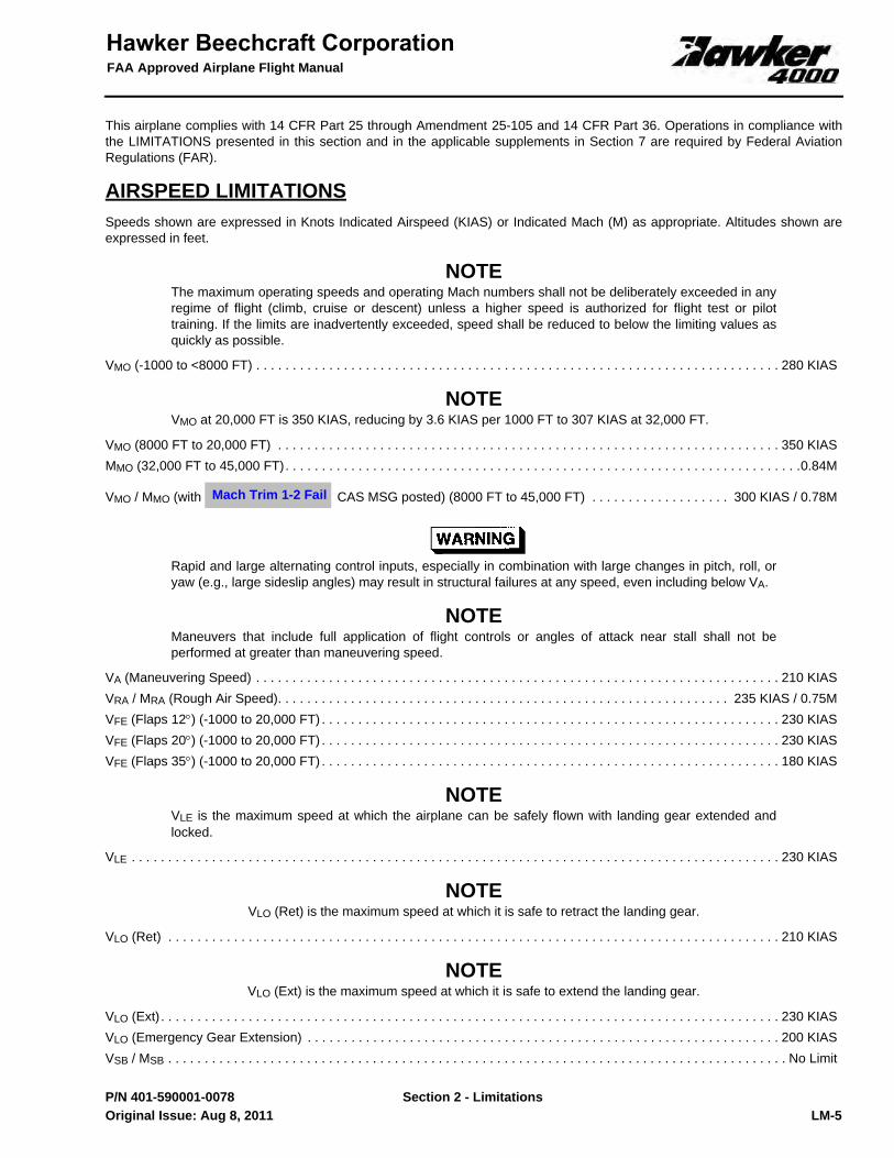
This airplane complies with 14 CFR Part 25 through Amendment 25-105 and 14 CFR Part 36. Operations in compliance withthe LIMITATIONS presented in this section and in the applicable supplements in Section 7 are required by Federal AviationRegulations (FAR).
AIRSPEED LIMITATIONSSpeeds shown are expressed in Knots Indicated Airspeed (KIAS) or Indicated Mach (M) as appropriate. Altitudes shown areexpressed in feet.
NOTEThe maximum operating speeds and operating Mach numbers shall not be deliberately exceeded in anyregime of flight (climb, cruise or descent) unless a higher speed is authorized for flight test or pilottraining. If the limits are inadvertently exceeded, speed shall be reduced to below the limiting values asquickly as possible.
VMO (-1000 to <8000 FT) . . . . . . . . . . . . . . . . . . . . . . . . . . . . . . . . . . . . . . . . . . . . . . . . . . . . . . . . . . . . . . . . . . . . . . . . 280 KIAS
NOTEVMO at 20,000 FT is 350 KIAS, reducing by 3.6 KIAS per 1000 FT to 307 KIAS at 32,000 FT.
VMO (8000 FT to 20,000 FT) . . . . . . . . . . . . . . . . . . . . . . . . . . . . . . . . . . . . . . . . . . . . . . . . . . . . . . . . . . . . . . . . . . . . . 350 KIASMMO (32,000 FT to 45,000 FT). . . . . . . . . . . . . . . . . . . . . . . . . . . . . . . . . . . . . . . . . . . . . . . . . . . . . . . . . . . . . . . . . . . . . . .0.84M
VMO / MMO (with CAS MSG posted) (8000 FT to 45,000 FT) . . . . . . . . . . . . . . . . . . . 300 KIAS / 0.78M
Rapid and large alternating control inputs, especially in combination with large changes in pitch, roll, oryaw (e.g., large sideslip angles) may result in structural failures at any speed, even including below VA.
NOTEManeuvers that include full application of flight controls or angles of attack near stall shall not beperformed at greater than maneuvering speed.
VA (Maneuvering Speed) . . . . . . . . . . . . . . . . . . . . . . . . . . . . . . . . . . . . . . . . . . . . . . . . . . . . . . . . . . . . . . . . . . . . . . . . 210 KIASVRA / MRA (Rough Air Speed). . . . . . . . . . . . . . . . . . . . . . . . . . . . . . . . . . . . . . . . . . . . . . . . . . . . . . . . . . . . . . 235 KIAS / 0.75MVFE (Flaps 12°) (-1000 to 20,000 FT) . . . . . . . . . . . . . . . . . . . . . . . . . . . . . . . . . . . . . . . . . . . . . . . . . . . . . . . . . . . . . . . 230 KIASVFE (Flaps 20°) (-1000 to 20,000 FT) . . . . . . . . . . . . . . . . . . . . . . . . . . . . . . . . . . . . . . . . . . . . . . . . . . . . . . . . . . . . . . . 230 KIASVFE (Flaps 35°) (-1000 to 20,000 FT) . . . . . . . . . . . . . . . . . . . . . . . . . . . . . . . . . . . . . . . . . . . . . . . . . . . . . . . . . . . . . . . 180 KIAS
NOTEVLE is the maximum speed at which the airplane can be safely flown with landing gear extended andlocked.
VLE . . . . . . . . . . . . . . . . . . . . . . . . . . . . . . . . . . . . . . . . . . . . . . . . . . . . . . . . . . . . . . . . . . . . . . . . . . . . . . . . . . . . . . . . . 230 KIAS
NOTEVLO (Ret) is the maximum speed at which it is safe to retract the landing gear.
VLO (Ret) . . . . . . . . . . . . . . . . . . . . . . . . . . . . . . . . . . . . . . . . . . . . . . . . . . . . . . . . . . . . . . . . . . . . . . . . . . . . . . . . . . . . 210 KIAS
NOTEVLO (Ext) is the maximum speed at which it is safe to extend the landing gear.
VLO (Ext) . . . . . . . . . . . . . . . . . . . . . . . . . . . . . . . . . . . . . . . . . . . . . . . . . . . . . . . . . . . . . . . . . . . . . . . . . . . . . . . . . . . . . 230 KIASVLO (Emergency Gear Extension) . . . . . . . . . . . . . . . . . . . . . . . . . . . . . . . . . . . . . . . . . . . . . . . . . . . . . . . . . . . . . . . . . 200 KIASVSB / MSB . . . . . . . . . . . . . . . . . . . . . . . . . . . . . . . . . . . . . . . . . . . . . . . . . . . . . . . . . . . . . . . . . . . . . . . . . . . . . . . . . . . . . No Limit
Mach Trim 1-2 Fail
Original Issue: Aug 8, 2011

FAA Approved Airplane Flight Manual
Section 2 - LimitationsLM-6 P/N 401-590001-0078
VMCG . . . . . . . . . . . . . . . . . . . . . . . . . . . . . . . . . . . . . . . . . . . . . . . . . . . . . . . . . . . . . . . . . . . . . . . . . . . . . . . . . . . . . . . . . 85 KIASVMCA (Flaps UP) . . . . . . . . . . . . . . . . . . . . . . . . . . . . . . . . . . . . . . . . . . . . . . . . . . . . . . . . . . . . . . . . . . . . . . . . . . . . . . . . 99 KIASVMCA (Flaps 12 and 20) . . . . . . . . . . . . . . . . . . . . . . . . . . . . . . . . . . . . . . . . . . . . Less Than Stick Pusher Speed At All WeightsVMCL . . . . . . . . . . . . . . . . . . . . . . . . . . . . . . . . . . . . . . . . . . . . . . . . . . . . . . . . . . . Less Than Stick Pusher Speed At All WeightsVTIRE . . . . . . . . . . . . . . . . . . . . . . . . . . . . . . . . . . . . . . . . . . . . . . . . . . . . . . . . . . . . . . . . . . . . . . . . 182 KT (True Ground Speed)
Original Issue: Aug 8, 2011

Section 2 - Limitations
FAA Approved Airplane Flight Manual
LM-7 P/N 401-590001-0078
FIGURE 1AIRSPEED / ALTITUDE - ENVELOPE
RC
02D
07
3633
AB.
AI
-500
00
5000
1000
0
1500
0
2000
0
2500
0
3000
0
3500
0
4000
0
4500
0
5000
0
050
100
150
200
250
300
350
400
MA
X A
LTIT
UD
E, F
LAP
S O
R G
EA
R E
XTE
ND
ED
VFE FLAPS 35
VFE
FLA
PS
12
& 2
0,
V LE /
V LO
(EX
T)
VRA / MRA = 235 KIAS / 0.75 M
V MO
MM
O =
0.8
4
8000
32,0
00
307
228
VLO(RET)201
38,2
50
AIR
SP
EE
D ~
KIA
S
PRESSURE ALTITUDE ~ FEET
Original Issue: Aug 8, 2011

FAA Approved Airplane Flight Manual
Section 2 - LimitationsLM-8 P/N 401-590001-0078
ALTITUDE LIMITATIONSExtremes of Ambient Air Temperature and Operating Altitude. . . . . . . . . . . . . . . . . . . . . . . . . . . . . . . . . . . . . Refer To Figure 5
Maximum Pressure Altitude with CAS MSG Posted . . . . . . . . . . . . . . . . . . . . . . . . . . . . . . . 35,000 FT
Maximum Operating Pressure Altitude . . . . . . . . . . . . . . . . . . . . . . . . . . . . . . . . . . . . . . . . . . . . . . . . . . . . . . . . . . . . . 45,000 FTMaximum Pressure Altitude with Landing Gear Extended . . . . . . . . . . . . . . . . . . . . . . . . . . . . . . . . . . . . . . . . . . . . . . 20,000 FTMaximum Pressure Altitude with Flaps Extended. . . . . . . . . . . . . . . . . . . . . . . . . . . . . . . . . . . . . . . . . . . . . . . . . . . . . 20,000 FTMaximum Airfield Elevation (Pressure Altitude) . . . . . . . . . . . . . . . . . . . . . . . . . . . . . . . . . . . . . . . . . . . . . . . . . . . . . . 12,000 FTMinimum Airfield Elevation (Pressure Altitude) . . . . . . . . . . . . . . . . . . . . . . . . . . . . . . . . . . . . . . . . . . . . . . . . . . . . . . . . -1000 FT
TEMPERATURE LIMITSAmbient Air Temperature . . . . . . . . . . . . . . . . . . . . . . . . . . . . . . . . . . . . . . . . . . . . . . . . . . . . . . . . . . . . . . . . . Refer To Figure 5
FLIGHT CONTROL LIMITSMaximum Flap Position with Speedbrake Extended. . . . . . . . . . . . . . . . . . . . . . . . . . . . . . . . . . . . . . . . . . . . . . . . . . . . . . . . .20°
Minimum Altitude with Speedbrake Extended. . . . . . . . . . . . . . . . . . . . . . . . . . . . . . . . . . . . . . . . . . . . . . . . . . . . . . .600 FT AGL
STALL WARNING PROTECTION SYSTEMThe normalized AOA indication on PFD may be used as a reference providing the PFD airspeed display is used as primaryreference.The green line (AOA indication 0.6) indicates the minimum speed that can be used on approach in flap position 35°, 20° and12°.The green line is not to be used as minimum speed on the approach with FLAPS UP / 0°.Intentional stalls are prohibited with a stall protection system CAS MSG displayed.
WEIGHT LIMITS
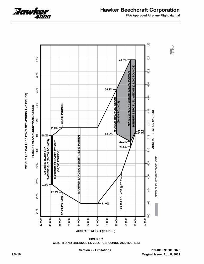
STRUCTURAL LIMITATIONSMaximum Ramp and Taxi Weight . . . . . . . . . . . . . . . . . . . . . . . . . . . . . . . . . . . . . . . . . . . . . . . . . . . . . . . 39,700 LB (18,008 KG)Maximum Take-off Weight . . . . . . . . . . . . . . . . . . . . . . . . . . . . . . . . . . . . . . . . . . . . . . . . . . . . . . . . . . . . 39,500 LB (17,917 KG)
NOTEPerform inspection specified in Chapter 05-50-00 of the Model 4000 Aircraft Maintenance Schedule inthe event of an overweight landing.
Maximum Landing Weight. . . . . . . . . . . . . . . . . . . . . . . . . . . . . . . . . . . . . . . . . . . . . . . . . . . . . . . . . . . . . 33,500 LB (15,195 KG)Maximum Zero Fuel Weight . . . . . . . . . . . . . . . . . . . . . . . . . . . . . . . . . . . . . . . . . . . . . . . . . . . . . . . . . . . 26,000 LB (11,793 KG)Minimum Zero Fuel Weight . . . . . . . . . . . . . . . . . . . . . . . . . . . . . . . . . . . . . . . . . . . . . . . . . . . . . . . . . . . . . 22,000 LB (9,979 KG)Aft Baggage Compartment Weight Limit. . . . . . . . . . . . . . . . . . . . . . . . . . . . . . . . . . . . . . . . . . . . . . . . . . . . . . . 900 LB (408 KG)Forward Closet Weight Limit . . . . . . . . . . . . . . . . . . . . . . . . . . . . . . . . . . . . . . . . . . . . . . . . . . . . . . . . . . . . . . . . . . 50 LB (23 KG)Aft Closet Weight Limit . . . . . . . . . . . . . . . . . . . . . . . . . . . . . . . . . . . . . . . . . . . . . . . . . . . . . . . . . . . . . . . . . . . . . . 40 LB (18 KG)Maximum Cabin Floor Loading . . . . . . . . . . . . . . . . . . . . . . . . . . . . . . . . . . . . . . . . . . . . . . . . 80 LB / SQ. FT (391 KG / SQ. M.)Maximum Aft Baggage Compartment Floor Loading . . . . . . . . . . . . . . . . . . . . . . . . . . . . . . 100 LB / SQ. FT (488 KG / SQ. M.)Maximum Fuel Imbalance. . . . . . . . . . . . . . . . . . . . . . . . . . . . . . . . . . . . . . . . . . . . . . . . . . . . . . . . . . . . . . . . . . 500 LB (227 KG)
Empty weight is determined in accordance with the information provided in the applicable Weight and Balance Manual, whichincludes the necessary loading instructions.
Yaw Damper 1-2 Fail
Original Issue: Aug 8, 2011

Section 2 - Limitations
FAA Approved Airplane Flight Manual
LM-9 P/N 401-590001-0078
TAKE-OFF WEIGHTMaximum Take-off Weight is limited by the most restrictive of the following:
• 39,500 LB (17,917 KG).• Climb Requirements in SECTION 5 - PERFORMANCE - TAKEOFF.• Take-off Field Length in SECTION 5 - PERFORMANCE - TAKEOFF.• Maximum Brake Energy in SECTION 5 - PERFORMANCE - TAKEOFF.
LANDING WEIGHTMaximum Landing Weight is limited by the most restrictive of the following:
• 33,500 LB (15,195 KG).• Climb Requirements or Brake Energy Limits in SECTION 5 - PERFORMANCE - APPROACH AND LANDING.• Landing Distance in SECTION 5 - PERFORMANCE - APPROACH AND LANDING.
MINIMUM FLIGHT WEIGHT• 23,000 LB (10,433 KG).
Original Issue: Aug 8, 2011
FAA Approved Airplane Flight Manual
Section 2 - LimitationsLM-10 P/N 401-590001-0078
FIGURE 2WEIGHT AND BALANCE ENVELOPE (POUNDS AND INCHES)
RC
02D
0821
43A
A.A
I
WEI
GH
T A
ND
BA
LAN
CE
ENVE
LOPE
(PO
UN
D A
ND
INC
HES
)
PER
CEN
T M
EAN
AER
OD
YNA
MIC
CH
OR
D40
%38
%36
%34
%32
%30
%28
%26
%24
%22
%20
%
20,0
00
22,0
00
24,0
00
26,0
00
28,0
00
30,0
00
32,0
00
34,0
00
36,0
00
38,0
00
40,0
00
42,0
00
400
402
404
406
408
410
412
414
416
418
420
422
424
426
AIR
CR
AFT
STA
TIO
N (I
NC
HES
)
AIRCRAFT WEIGHT (POUNDS)
MA
XIM
UM
TA
KE-
OFF
WEI
GH
T(3
9,50
0 PO
UN
DS)
MAX
IMUM
ZER
O F
UEL
WEI
GHT
(26,
000
POU
ND
S)
MA
XIM
UM
LA
ND
ING
WEI
GH
T (3
3,50
0 PO
UN
DS)
MA
XIM
UM
RA
MP
AN
D T
AXI
WEI
GH
T (3
9,70
0 PO
UN
DS)
23.5%
30.2%
21.0%
30.0%
25,0
00 P
OU
ND
S @
25.
0%
MIN
IMU
M F
LIG
HT
WEI
GH
T (2
3,00
0 PO
UN
DS)
28.5%
36.1%
37,5
00 P
OUN
DS37
,500
PO
UN
DS
22.5%
31.0%
29.2%
40.0%
30.5%30.3%M
INIM
UM
ZER
O F
UEL
WEI
GH
T (2
2,00
0 PO
UN
DS)
ZER
O F
UEL
WEI
GH
T EN
VELO
PE
Original Issue: Aug 8, 2011

Section 2 - Limitations
FAA Approved Airplane Flight Manual
LM-11 P/N 401-590001-0078
FIGURE 3WEIGHT AND BALANCE ENVELOPE (KILOGRAMS AND CENTIMETERS)
RC
02D
0821
44A
A.A
I
WEI
GH
T A
ND
BA
LAN
CE
ENVE
LOPE
(KIL
OG
RA
MS
AN
D C
ENTI
MET
ERS)
PER
CEN
T M
EAN
AER
OD
YNA
MIC
CH
OR
D40
%38
%36
%34
%32
%30
%28
%26
%24
%22
%20
%
9,00
0
10,0
00
11,0
00
12,0
00
13,0
00
14,0
00
15,0
00
16,0
00
17,0
00
18,0
00
19,0
00 1,01
51,
020
1,02
51,
030
1,03
51,
040
1,04
51,
050
1,05
51,
060
1,06
51,
070
1,07
51,
080
AIR
CR
AFT
STA
TIO
N (C
ENTI
MET
ERS)
AIRCRAFT WEIGHT (KILOGRAMS)
MA
XIM
UM
TA
KE-
OFF
WEI
GH
T(1
7,91
7 K
ILO
GR
AM
S)
MAX
IMUM
ZER
O F
UEL
WEI
GHT
(11,
793
KIL
OG
RA
MS)
MA
XIM
UM
LA
ND
ING
WEI
GH
T (1
5,19
5 K
ILO
GR
AM
S)
MA
XIM
UM
RA
MP
AN
DTA
XI W
EIG
HT
(18,
008
KIL
OG
RA
MS)
23.5%
30.2%
21.0%
30.0%
MIN
IMU
M F
LIG
HT
WEI
GH
T (1
0,43
3 K
ILO
GR
AM
S)28.5%
36.1%
17,01
0 KIL
OG
RAM
S17
,010
KIL
OG
RA
MS
22.5%
31.0%
29.2%
40.0%
30.5%30.3%
11,3
40 K
ILO
GR
AM
S @
25.
0%
MIN
IMU
M Z
ERO
FU
EL W
EIG
HT
(9,9
79 K
ILO
GR
AM
S)
ZER
O F
UEL
WEI
GH
T EN
VELO
PE
Original Issue: Aug 8, 2011
FAA Approved Airplane Flight Manual
Section 2 - LimitationsLM-12 P/N 401-590001-0078
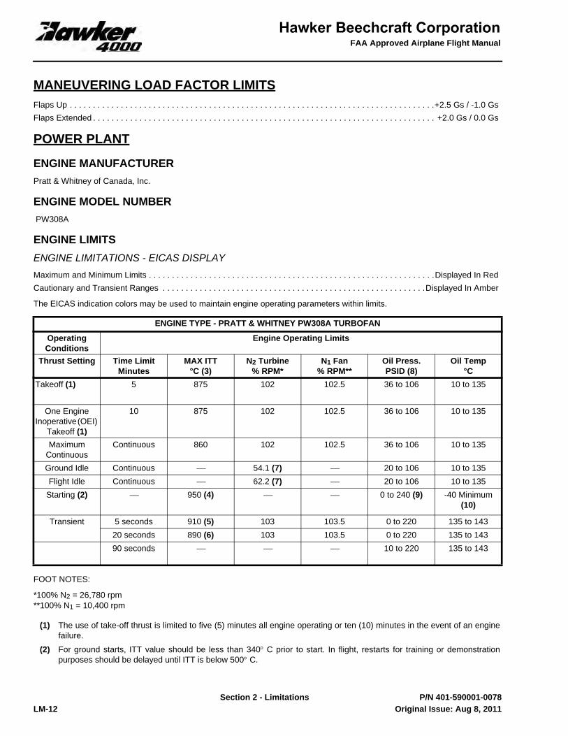
MANEUVERING LOAD FACTOR LIMITSFlaps Up . . . . . . . . . . . . . . . . . . . . . . . . . . . . . . . . . . . . . . . . . . . . . . . . . . . . . . . . . . . . . . . . . . . . . . . . . . . . . . .+2.5 Gs / -1.0 GsFlaps Extended . . . . . . . . . . . . . . . . . . . . . . . . . . . . . . . . . . . . . . . . . . . . . . . . . . . . . . . . . . . . . . . . . . . . . . . . . . +2.0 Gs / 0.0 Gs
POWER PLANT
ENGINE MANUFACTURERPratt & Whitney of Canada, Inc.
ENGINE MODEL NUMBER PW308A
ENGINE LIMITSENGINE LIMITATIONS - EICAS DISPLAYMaximum and Minimum Limits . . . . . . . . . . . . . . . . . . . . . . . . . . . . . . . . . . . . . . . . . . . . . . . . . . . . . . . . . . . . . .Displayed In RedCautionary and Transient Ranges . . . . . . . . . . . . . . . . . . . . . . . . . . . . . . . . . . . . . . . . . . . . . . . . . . . . . . . . .Displayed In Amber
The EICAS indication colors may be used to maintain engine operating parameters within limits.
FOOT NOTES:
*100% N2 = 26,780 rpm**100% N1 = 10,400 rpm
ENGINE TYPE - PRATT & WHITNEY PW308A TURBOFAN
Operating Conditions
Engine Operating Limits
Thrust Setting Time LimitMinutes
MAX ITT°C (3)
N2 Turbine% RPM*
N1 Fan% RPM**
Oil Press.PSID (8)
Oil Temp°C
Takeoff (1) 5 875 102 102.5 36 to 106 10 to 135
One Engine Inoperative (OEI)
Takeoff (1)
10 875 102 102.5 36 to 106 10 to 135
MaximumContinuous
Continuous 860 102 102.5 36 to 106 10 to 135
Ground Idle Continuous ⎯ 54.1 (7) ⎯ 20 to 106 10 to 135Flight Idle Continuous ⎯ 62.2 (7) ⎯ 20 to 106 10 to 135
Starting (2) ⎯ 950 (4) ⎯ ⎯ 0 to 240 (9) -40 Minimum (10)
Transient 5 seconds 910 (5) 103 103.5 0 to 220 135 to 14320 seconds 890 (6) 103 103.5 0 to 220 135 to 14390 seconds ⎯ ⎯ ⎯ 10 to 220 135 to 143
(1) The use of take-off thrust is limited to five (5) minutes all engine operating or ten (10) minutes in the event of an enginefailure.
(2) For ground starts, ITT value should be less than 340° C prior to start. In flight, restarts for training or demonstrationpurposes should be delayed until ITT is below 500° C.
Original Issue: Aug 8, 2011
Section 2 - Limitations
FAA Approved Airplane Flight Manual
1 of 4
401-590001-0078TC1
THIS PAGE INTENTIONALLY LEFT BLANK
Apr 12, 2012

FAA Approved Airplane Flight Manual
Section 2 - Limitations
2 of 4
401-590001-0078TC1
Temporary Changeto the
FAA Approved Airplane Flight Manual
P/N 401-590001-0078TC1
SECTION 2 - LIMITATIONS
POWER PLANT
ENGINE LIMITS
Read the following information prior to the HEADER, WIND LIMITATIONS FOR GROUND STARTS:
ENGINE TIME LIMITED DISPATCH
For operational dispatch procedures, when any of the CAS MSGs below are posted, refer to Section 3B - Advisory/StatusProcedures.
Allowable times for dispatch with the CAS MSGs below, may not exceed the following manufacturer’s limits:
• or CAS MSG posted - maximum 125 hours or 120 days, whichever
comes first.
• or CAS MSG posted - maximum 600 hours or 24 months, whichever
comes first.
by: ___________________________________________ Margaret Kline, Manager Aircraft Certification Office Federal Aviation Administration Wichita, Kansas
Approval Date: __________________________________
FAA Approved
Publication Affected FAA Approved Airplane Flight Manual, P/N 401-590001-0078, dated Aug 8, 2011, or later revision for Hawker Model 4000 Airplanes.
Airplane Serial Numbers Affected
RC-59 and After or Prior Airplane Serials with Kit 401-3007 or 401-3008 or 401-3027 or 401-3028 Installed for Block Point Upgrade A.
Description of Change 1. Added new header ENGINE TIME LIMITED DISPATCH with data.
2. Revised Cyan “L, R, L-R FADEC Long TLD” CAS MSGs with new Dispatch procedure.
3. Revised Cyan “L, R, L-R FADEC Short TLD” CAS MSGs with new Dispatch procedure.
Filing Instructions Insert Page 2 of 4 to face page LM-13 in Section 2 - Limitations,Insert Page 3 of 4 to face page AS-10 in Section 3B - Advisory/Status Procedures,Insert Page 4 of 4 to face page AS-11 in Section 3B - Advisory/Status Procedures.
# FADEC Short TLD #-# FADEC Short TLD
# FADEC Long TLD #-# FADEC Long TLD
Apr 12, 2012

Section 2 - Limitations
FAA Approved Airplane Flight Manual
LM-13 P/N 401-590001-0078
WIND LIMITATIONS FOR GROUND STARTSMaximum steady crosswind for ground starts is 25 KT.
Maximum steady tailwind for ground starts is 10 KT.
ENGINE SHUTDOWN LIMITSEngines must have run in idle for a minimum of 2 minutes before a normal shutdown.
APPROVED POWER PLANT OILS (PRATT & WHITNEY PW308A)
Mixing oils of different brands is not recommended; however, any mixing shall be limited to 2 U.S. quarts in any 600-hour oilchange interval.
AIR TURBINE STARTER LIMITSStarter operation is limited to three cycles, with a minimum of 3.5 minutes off between each cycle. After three cycles, 5 minutesOFF is required. A cycle is a start attempt, a wet spin, or a dry spin.
For engine motoring cycles with no ignition (wet and dry spins) lasting longer than 30 seconds and above an ambient tempera-ture of 30° C (86° F), the lower cowl door must be opened.
(3) ITT is monitored by the Full Authority Digital Engine Control (FADEC). If an exceedance occurs, the Engine Indication andCrew Alerting System (EICAS) indications will prompt necessary crew action. Exceedance may arise due to the endingof a time limit in the case of a transient value. Refer to the Model 4000 Airplane Maintenance Manual to determinecorrective action if an exceedance has been recorded.
(4) The higher start ITT is permitted from start switch press to stabilized idle N2. Report incident in Engine Logbook ifexceeded.
(5) ITT transient of 910° C is permitted for first 5 seconds after takeoff N1 achieved.
(6) ITT transient of 890° C is permitted for 20 seconds except during takeoff when it is permitted for 45 seconds.
(7) Flight Idle should be maintained above 62.2% stable N2 to ensure satisfactory acceleration times. Transient reductionsof 2% rpm are permissible.
(8) The normal steady oil pressure indication is between 36 PSI and 106 PSI. Continuous engine operation with oil pressurebelow 20 PSI is prohibited. Between 20 PSI and 36 PSI, N2 should be kept below 88% but higher N2 may be tolerated forthe completion of a flight if the oil temperature can be maintained within limits.
(9) Oil pressure above 106 PSI is permitted during cold starting (oil temperature below 0° C). It is acceptable to run the engineup to Maximum Cruise in order to warm the oil to 10° C. During the time the oil temperature is below 10° C, a maximumoil pressure of 220 PSI applies. The engine should be run for an additional 3 minutes beyond the time10° C is reached to ensure no ice particles are present in the fuel supply lines prior to flight.
(10) If oil temperature is below -40° C, the oil should be heated by means of dry motoring.
Aero Shell Turbine Oil 500 Royco Turbine Oil 500
Mobil Jet Oil II Castrol 5000
BP Turbo Oil 2380 TurboNycoil TN 600
Original Issue: Aug 8, 2011

FAA Approved Airplane Flight Manual
Section 2 - LimitationsLM-14 P/N 401-590001-0078
CROSS BLEED N2 STARTER LIMITS (GROUND ONLY) Maintain starter within bleed temperature limits (Refer to Figure 4).
FIGURE 4MINIMUM N2 CROSS BLEED START (GROUND STARTS ONLY)
Min
imum
N2
Spee
d re
quire
d fo
r ble
ed p
ress
ure
and
flow
& M
axim
um N
2 Sp
eed
to m
aint
ain
star
ter w
ithin
ble
ed te
mpe
ratu
re li
mit
For G
roun
d C
ross
Sta
rting
of P
W30
8A w
ith n
o ai
rcra
ft se
rvic
es b
leed
flow
.
757677787980818283848586878889909192939495
-40
-35
-30
-25
-20
-15
-10
-50
510
1520
2530
3540
4550
55
Ambi
ent T
empe
ratu
re (C
)
N2 (%)
0ft
Blee
d Te
mpe
ratu
re
Lim
it M
axim
um60
00ft
3000
ft
12,0
00ft
9000
ft
-100
0ft
Pres
sure
Alti
tude
RC
02D
06
2025
AA.A
I
Original Issue: Aug 8, 2011

Section 2 - Limitations
FAA Approved Airplane Flight Manual
LM-15 P/N 401-590001-0078
POWER PLANT DISPLAY MARKINGSN1 (Fan Speed)-(Analog Combined with Digital Display)
Normal Operating Range (White analog and digital displays) . . . . . . . . . . . . . . . . . . . . . . . . . . . . . . . . . . . . 10% to 102.5%Transient Limit (Amber radial line on analog display) . . . . . . . . . . . . . . . . . . . . . . . . . . . . . . . . . . . . . . . . . . . . . . . . 102.5%Transient Range (Amber analog and digital displays for 20 seconds, then Red) . . . . . . . . . . . . . . . . . . >102.5% to 103.5%Maximum Limit (Red radial line on analog display) . . . . . . . . . . . . . . . . . . . . . . . . . . . . . . . . . . . . . . . . . . . . . . . . . . 103.5%Maximum Limit (Red analog and digital display) . . . . . . . . . . . . . . . . . . . . . . . . . . . . . . . . . . . . . . . . . . . . . . . . . . . . 103.5%
N2 (Core Speed)-(Digital Display)Ground Idle Minimum. . . . . . . . . . . . . . . . . . . . . . . . . . . . . . . . . . . . . . . . . . . . . . . . . . . . . . . . . . . . . . . . . . . . . . . . . . 54.1%Flight Idle Minimum (Amber digital display when below scheduled idle while airborne) . . . . . . . . . . . . . . . . . . . . . . . 62.2%Normal Operating Range (White digital display) . . . . . . . . . . . . . . . . . . . . . . . 54.1% (Ground) or 62.2% (Flight) to 102.0%Transient Range (Amber digital display for 20 seconds, then Red). . . . . . . . . . . . . . . . . . . . . . . . . . . . . >102.0% to 103.0%Maximum Limit (Red digital display) . . . . . . . . . . . . . . . . . . . . . . . . . . . . . . . . . . . . . . . . . . . . . . . . . . . . . . . . . . . . . 103.0%
ITT (Inter Turbine Temperature)-(Analog Combined with Digital Display)Normal Operating Range (White analog and digital displays) . . . . . . . . . . . . . . . . . . . . . . . . . . . . . . . . . . . . . . . . . . <860° CMaximum Continuous Limit (Amber radial line on analog display) . . . . . . . . . . . . . . . . . . . . . . . . . . . . . . . . . . . . . . . 860° CNormal Take-off Range (White analog and digital displays for first 280 seconds) . . . . . . . . . . . . . . . . . . >860° C to 875° COne Engine Inoperative (OEI) Take-off Range(White analog and digital displays for first 580 seconds). . . . . . . . . . . . . . . . . . . . . . . . . . . . . . . . . . . . . . >860° C to 875° CTake-off Range (Amber analog and digital displays first 5 seconds, then Red) . . . . . . . . . . . . . . . . . . . . >890° C to 910° CNormal Take-off Range(Amber analog and digital displays from 280 seconds to 5 minutes, then Red) . . . . . . . . . . . . . . . . . . . . >860° C to 875° COEI Take-off Range (Amber analog and digital displays from 580 seconds to 10 minutes, then Red) . . . >860° C to 875° CTransient (Red radial line on analog display). . . . . . . . . . . . . . . . . . . . . . . . . . . . . . . . . . . . . . . . . . . . . . . . . . . . . . . . 875° CTransient Range (Amber analog and digital displays for 20 seconds, then Red) . . . . . . . . . . . . . . . . . . . >875° C to 890° CTake-off Range (Amber analog and digital displays from 25 to 45 seconds) . . . . . . . . . . . . . . . . . . . . . . . 875° C to 890° C
(From 45 to 180 seconds tapers). . . . . . . . . . . . . . . . . . . . . . . . . . . . . . . . . . . . . . . . . . . . . . . . . . . . . . 890° C to 875° CMaximum (Red analog and digital displays) . . . . . . . . . . . . . . . . . . . . . . . . . . . . . . . . . . . . . . . . . . . . . . . . . . . . . . . >910° CStarting (Red radial line on analog display) . . . . . . . . . . . . . . . . . . . . . . . . . . . . . . . . . . . . . . . . . . . . . . . . . . . . . . 950° C (1)Starting (Red analog and digital displays) . . . . . . . . . . . . . . . . . . . . . . . . . . . . . . . . . . . . . . . . . . . . . . . . . . . . . . . 950° C (1)Starting (reset red line) . . . . . . . . . . . . . . . . . . . . . . . . . . . . . . . . . . . . . . . . . . . . . . . . . . . . . . . . . . . . . . . . . . . . . . . . 950° C
FOOT NOTE:
Oil Temperature (Digital Display)Maximum (Red digital display). . . . . . . . . . . . . . . . . . . . . . . . . . . . . . . . . . . . . . . . . . . . . . . . . . . . . . . . . . . . . . . . . . >143° CHigh Transient Range (White digital display 0 to 70 seconds, Amber for 20 seconds, then Red). . . . . . . >135° C to 143° CNormal Operating Range (White digital display) . . . . . . . . . . . . . . . . . . . . . . . . . . . . . . . . . . . . . . . . . . . . . . 10° C to 135° CLow Transient Range (Amber digital display) . . . . . . . . . . . . . . . . . . . . . . . . . . . . . . . . . . . . . . . . . . . . . . . . -40° C to 10° CMinimum Starting Limit (Amber digital display) . . . . . . . . . . . . . . . . . . . . . . . . . . . . . . . . . . . . . . . . . . . . . . . . . . . . . . -40° C
(1) Active during the start cycle only. For starting temperatures in excess of 950° C, consult the Model 4000 AirplaneMaintenance Manual.
Original Issue: Aug 8, 2011

FAA Approved Airplane Flight Manual
Section 2 - LimitationsLM-16 P/N 401-590001-0078
Oil Pressure (Digital Display)Maximum (Red digital display) . . . . . . . . . . . . . . . . . . . . . . . . . . . . . . . . . . . . . . . . . . . . . . . . . . . . . . . . . . . . . . . . . >220 PSIHigh Transient Range (White digital display 0 to 70 seconds, Amber for 20 seconds, then Red) . . . . . >106 PSI to 220 PSINormal Operating Range (White digital display) N2 >88%. . . . . . . . . . . . . . . . . . . . . . . . . . . . . . . . . . . . . 36 PSI to 106 PSINormal Operating Range (White digital display) N2 <88%. . . . . . . . . . . . . . . . . . . . . . . . . . . . . . . . . . . . . 20 PSI to 106 PSILow Transient Range (Amber digital display) N2 >88% . . . . . . . . . . . . . . . . . . . . . . . . . . . . . . . . . . . . . . . 20 PSI to <36 PSI
(White digital display 0 to 70 seconds then Amber)Low Transient Range (White for 70 seconds, Amber for 20 seconds, then Red) . . . . . . . . . . . . . . . . . . . 10 PSI to <20 PSILow Transient Range (Amber for 20 seconds, then Red) . . . . . . . . . . . . . . . . . . . . . . . . . . . . . . . . . . . . . 0 PSI to <10 PSIStarting Limit (Red digital display) . . . . . . . . . . . . . . . . . . . . . . . . . . . . . . . . . . . . . . . . . . . . . . . . . . . . . . . . . . . . . . >240 PSI
Vibration (Digital Display)Digital scale of vibration level for both engines will be displayed above 0.8 on either engine.Normal Decluttered Operation (No digital display) . . . . . . . . . . . . . . . . . . . . . . . . . . . . . . . . . . . . . . . . . . . . . . . . . . 0.0 to 0.8Awareness Level Operation (White digital display for both engines) . . . . . . . . . . . . . . . . . . . . . . . . . . . . . . . . . . 0.81 to 0.95Caution Level Operation (Amber digital display for affected engine) . . . . . . . . . . . . . . . . . . . . . . . . . . . . . . . . . . . 0.96 to 1.0Warning Level Operation (Red digital display for affected engine) . . . . . . . . . . . . . . . . . . . . . . . . . . . . . . . . . . . . . . . . . >1.0Vibration display is removed when levels for both engines are below 0.81 for 5 minutes.
THRUST REVERSERSUsing Thrust Reversers for power back is prohibited.Thrust Reversers may not be deployed statically, unless required by an operational check.Below taxi speed, Thrust Reversers must be stowed.Minimum speed for maximum reverse thrust is 60 KIAS.The use of Thrust Reversers is prohibited for Touch-and-go landings.Thrust Reversers must be operated (deployed and stowed) prior to each flight unless pinned as required per MEL.Thrust Reversers are for ground use only. Do not lift Thrust Reverse Levers in flight.
AUXILIARY POWER UNIT (APU) APU MODEL NUMBER Honeywell Engines, Systems & Services Model 36-150[HH]
APU LIMITS Maximum Pressure Altitude for In-Flight Starting or Operating the APU . . . . . . . . . . . . . . . . . . . . . . . . . . . . . . . . . . . 34,000 FTMinimum OAT for APU Starting on the ground. . . . . . . . . . . . . . . . . . . . . . . . . . . . . . . . . . . . . . . . . . . . . . . . . . . .-40° C (-40° F)Maximum Exhaust Gas Temperature (EGT). . . . . . . . . . . . . . . . . . . . . . . . . . . . . . . . . . . . . . . . . . . 974° C (Start); 718° C (Run)Rotor Speed for Nominal Full Load Governing . . . . . . . . . . . . . . . . . . . . . . . . . . . . . . . . . . . . . . . . . . . . . . . . . . . . .99% to 101%Rotor Speed for Automatic Shutdown (overspeed). . . . . . . . . . . . . . . . . . . . . . . . . . . . . . . . . . . . . . . . . . . . . . . . . . . . . . . . 108%The APU may not be started or intentionally shut down during fueling operations.The APU may not be operated during ground de-icing operations.The cockpit must be continuously monitored by personnel approved to operate the airplane if the APU is running and the White“APU Unattended Mode” CAS MSG is not posted.
With APU running and CAS MSG posted, a person approved to operate the airplane must be inaudible range of the airplane and APU. When stopping the APU, allow at least 5 seconds between EICAS APU display clearing and removal of Direct Current (DC)power from the airplane.APU must be off for takeoff until after landing gear is retracted.
APU Unattended Mode
Original Issue: Aug 8, 2011

Section 2 - Limitations
FAA Approved Airplane Flight Manual
LM-17 P/N 401-590001-0078
APPROVED APU OILS
Add oil of same specification and manufacturer’s brand as oil already in tank. Do not mix oils of differentspecifications or brands.
APU STARTER LIMITS 30 seconds ON, 30 seconds OFF30 seconds ON, 30 seconds OFF30 seconds ON, 20 minutes OFFNo more than 4 start attempts may be conducted in any 60 minute period.
APU BLEED Use of APU BLEED in flight is prohibited.
Aeroshell Turbine Oil 390 Brayco 880 Exxon / Esso Turbine Oil 2380
British Petroleum Aero Turbine Oil 15 Castrol 3C Exxon ETO 85
Castrol 325 Exxon / Esso Turbine Oil 2389 Hatcol 3611
Aeroshell 560 Castrol 5000 Mobil Jet Oil II / 254
Royco / Aeroshell Turbine Oil 500 / 555 Royco 899
Original Issue: Aug 8, 2011
FAA Approved Airplane Flight Manual
Section 2 - LimitationsLM-18 P/N 401-590001-0078
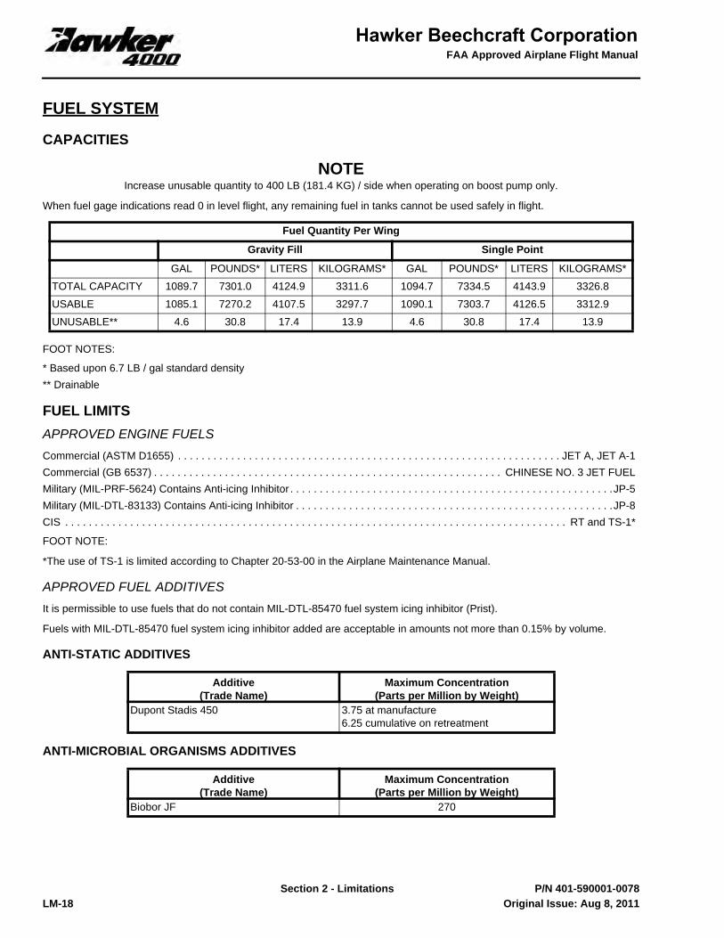
FUEL SYSTEM
CAPACITIES
NOTEIncrease unusable quantity to 400 LB (181.4 KG) / side when operating on boost pump only.
When fuel gage indications read 0 in level flight, any remaining fuel in tanks cannot be used safely in flight.
FOOT NOTES:
* Based upon 6.7 LB / gal standard density** Drainable
FUEL LIMITSAPPROVED ENGINE FUELSCommercial (ASTM D1655) . . . . . . . . . . . . . . . . . . . . . . . . . . . . . . . . . . . . . . . . . . . . . . . . . . . . . . . . . . . . . . . . . JET A, JET A-1Commercial (GB 6537) . . . . . . . . . . . . . . . . . . . . . . . . . . . . . . . . . . . . . . . . . . . . . . . . . . . . . . . . . . . CHINESE NO. 3 JET FUELMilitary (MIL-PRF-5624) Contains Anti-icing Inhibitor . . . . . . . . . . . . . . . . . . . . . . . . . . . . . . . . . . . . . . . . . . . . . . . . . . . . . . .JP-5Military (MIL-DTL-83133) Contains Anti-icing Inhibitor . . . . . . . . . . . . . . . . . . . . . . . . . . . . . . . . . . . . . . . . . . . . . . . . . . . . . .JP-8CIS . . . . . . . . . . . . . . . . . . . . . . . . . . . . . . . . . . . . . . . . . . . . . . . . . . . . . . . . . . . . . . . . . . . . . . . . . . . . . . . . . . . . . RT and TS-1*
FOOT NOTE:
*The use of TS-1 is limited according to Chapter 20-53-00 in the Airplane Maintenance Manual.
APPROVED FUEL ADDITIVESIt is permissible to use fuels that do not contain MIL-DTL-85470 fuel system icing inhibitor (Prist).
Fuels with MIL-DTL-85470 fuel system icing inhibitor added are acceptable in amounts not more than 0.15% by volume.
ANTI-STATIC ADDITIVES
ANTI-MICROBIAL ORGANISMS ADDITIVES
Fuel Quantity Per Wing
Gravity Fill Single Point
GAL POUNDS* LITERS KILOGRAMS* GAL POUNDS* LITERS KILOGRAMS*
TOTAL CAPACITY 1089.7 7301.0 4124.9 3311.6 1094.7 7334.5 4143.9 3326.8
USABLE 1085.1 7270.2 4107.5 3297.7 1090.1 7303.7 4126.5 3312.9
UNUSABLE** 4.6 30.8 17.4 13.9 4.6 30.8 17.4 13.9
Additive(Trade Name)
Maximum Concentration(Parts per Million by Weight)
Dupont Stadis 450 3.75 at manufacture6.25 cumulative on retreatment
Additive(Trade Name)
Maximum Concentration(Parts per Million by Weight)
Biobor JF 270
Original Issue: Aug 8, 2011

Section 2 - Limitations
FAA Approved Airplane Flight Manual
LM-19 P/N 401-590001-0078
LEAK CHECK ADDITIVE
FUEL TEMPERATURE LIMITSMinimum Fuel Temperature for Engine Start and On Ground . . . . . . . . . . . . . . . . . . . . . . . . . . . . . . . . . . . . . . . . -40° C (-40° F)Minimum Fuel Temperature for Takeoff and In Flight. . . . . . . . . . . . . . . . . . . . . . . . . . . . . . . . . . . . . . . . . . . . . . . -25° C (-13° F)Maximum Fuel Temperature. . . . . . . . . . . . . . . . . . . . . . . . . . . . . . . . . . . . . . . . . . . . . . . . . . . . . . . . . . . . . . . . . . 50° C (122° F)
When using TS-1 or RT fuel and the ambient temperature at takeoff is above 43° C (110° F), maximum altitude is limited to30,000 FT or below when:• Fuel temperature is above 30° C.• Fuel temperature cannot be determined in flight due to low fuel level in the left wing, unless previously indicated below 30° C.
Flights with fuel loads in excess of 7000 LB (3175 KG) total, require the crew to check fuel temperature before flight on FuelSynoptic to verify fuel temperature sensor is operational.
FUELING / DEFUELING LIMITSMaximum Fueling Pressure (single point refueling) . . . . . . . . . . . . . . . . . . . . . . . . . . . . . . . . . . . . . . . . . . . . . . . . . . . . . . 45 PSIMaximum Defueling Vacuum (single point defueling). . . . . . . . . . . . . . . . . . . . . . . . . . . . . . . . . . . . . . . . . . . . . . . . . . . . . .-3 PSI
FUEL TRANSFERThe use of FUEL TRANSFER is limited to ground operations only unless otherwise specified by an Emergency or AbnormalProcedure.
ELECTRICAL SYSTEM
MAIN GENERATOR LOAD LIMITSGround Operation. . . . . . . . . . . . . . . . . . . . . . . . . . . . . . . . . . . . . . . . . . . . . . . . . . . . . . . . . . . . . . . . . . . . . . . . . . . . . . . . . 100%In Flight Operation . . . . . . . . . . . . . . . . . . . . . . . . . . . . . . . . . . . . . . . . . . . . . . . . . . . . . . . . . . . . . . . . . . . . . . . . . . . . . . . . 100%
APU GENERATOR LOAD LIMITSGround Operation. . . . . . . . . . . . . . . . . . . . . . . . . . . . . . . . . . . . . . . . . . . . . . . . . . . . . . . . . . . . . . . . . . . . . . . .100% (16.7 KVA)In Flight Operation (-1000 FT to 26,000 FT). . . . . . . . . . . . . . . . . . . . . . . . . . . . . . . . . . . . . . . . . . . . . . . . . . . .100% (16.7 KVA)In Flight Operation (26,000 FT to 34,000 FT) . . . . . . . . . . . . . . . . . . . . . . . . . . . . . . . . . . . . . . . . . . . . . . . . . . . . 100% (10 KVA)
TRU LOAD LIMITSManual Restore of electrical loads is prohibited if TRU 1 or TRU 2 is failed.TRU 1 or 2 . . . . . . . . . . . . . . . . . . . . . . . . . . . . . . . . . . . . . . . . . . . . . . . . . . . . . . . . . . . . . . . . . . . . . . . . . . . . 100% (200 Amps)
Additive(Trade Name)
Maximum Concentration(Parts per Million)
Tracer A (Sulfur Hexafluoride, SF6) 1
Original Issue: Aug 8, 2011
FAA Approved Airplane Flight Manual
Section 2 - LimitationsLM-20 P/N 401-590001-0078
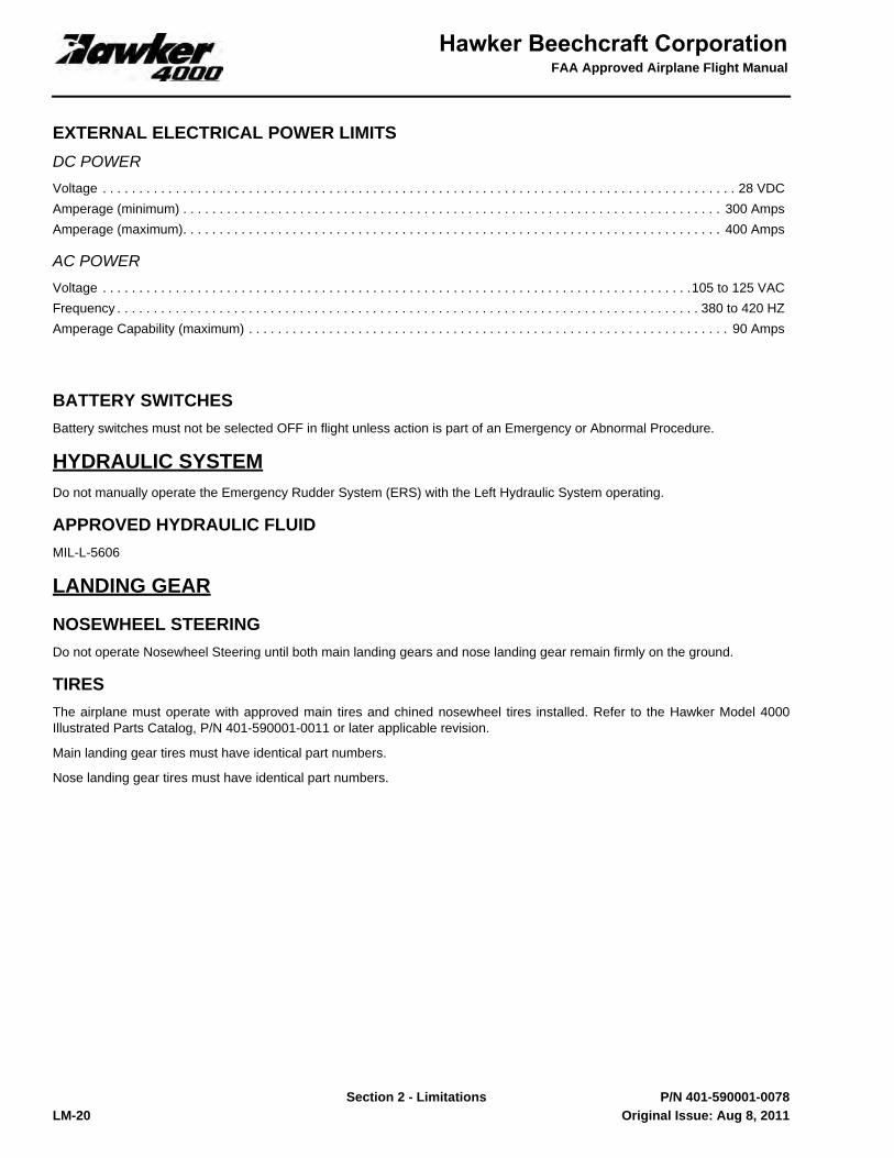
EXTERNAL ELECTRICAL POWER LIMITSDC POWERVoltage . . . . . . . . . . . . . . . . . . . . . . . . . . . . . . . . . . . . . . . . . . . . . . . . . . . . . . . . . . . . . . . . . . . . . . . . . . . . . . . . . . . . . . . 28 VDCAmperage (minimum) . . . . . . . . . . . . . . . . . . . . . . . . . . . . . . . . . . . . . . . . . . . . . . . . . . . . . . . . . . . . . . . . . . . . . . . . . . 300 AmpsAmperage (maximum). . . . . . . . . . . . . . . . . . . . . . . . . . . . . . . . . . . . . . . . . . . . . . . . . . . . . . . . . . . . . . . . . . . . . . . . . . 400 Amps
AC POWERVoltage . . . . . . . . . . . . . . . . . . . . . . . . . . . . . . . . . . . . . . . . . . . . . . . . . . . . . . . . . . . . . . . . . . . . . . . . . . . . . . . . .105 to 125 VACFrequency . . . . . . . . . . . . . . . . . . . . . . . . . . . . . . . . . . . . . . . . . . . . . . . . . . . . . . . . . . . . . . . . . . . . . . . . . . . . . . . . 380 to 420 HZAmperage Capability (maximum) . . . . . . . . . . . . . . . . . . . . . . . . . . . . . . . . . . . . . . . . . . . . . . . . . . . . . . . . . . . . . . . . . . 90 Amps
BATTERY SWITCHESBattery switches must not be selected OFF in flight unless action is part of an Emergency or Abnormal Procedure.
HYDRAULIC SYSTEMDo not manually operate the Emergency Rudder System (ERS) with the Left Hydraulic System operating.
APPROVED HYDRAULIC FLUIDMIL-L-5606
LANDING GEAR
NOSEWHEEL STEERINGDo not operate Nosewheel Steering until both main landing gears and nose landing gear remain firmly on the ground.
TIRESThe airplane must operate with approved main tires and chined nosewheel tires installed. Refer to the Hawker Model 4000Illustrated Parts Catalog, P/N 401-590001-0011 or later applicable revision.
Main landing gear tires must have identical part numbers.
Nose landing gear tires must have identical part numbers.
Original Issue: Aug 8, 2011
Section 2 - Limitations
FAA Approved Airplane Flight Manual
LM-21 P/N 401-590001-0078
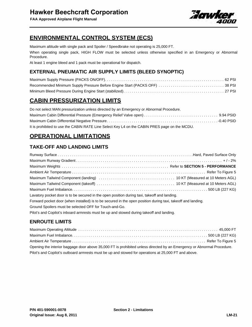
ENVIRONMENTAL CONTROL SYSTEM (ECS)Maximum altitude with single pack and Spoiler / Speedbrake not operating is 25,000 FT.When operating single pack, HIGH FLOW must be selected unless otherwise specified in an Emergency or AbnormalProcedure.At least 1 engine bleed and 1 pack must be operational for dispatch.
EXTERNAL PNEUMATIC AIR SUPPLY LIMITS (BLEED SYNOPTIC)Maximum Supply Pressure (PACKS ON/OFF). . . . . . . . . . . . . . . . . . . . . . . . . . . . . . . . . . . . . . . . . . . . . . . . . . . . . . . . . . 62 PSIRecommended Minimum Supply Pressure Before Engine Start (PACKS OFF) . . . . . . . . . . . . . . . . . . . . . . . . . . . . . . . . 38 PSIMinimum Bleed Pressure During Engine Start (stabilized). . . . . . . . . . . . . . . . . . . . . . . . . . . . . . . . . . . . . . . . . . . . . . . . . 27 PSI
CABIN PRESSURIZATION LIMITSDo not select MAN pressurization unless directed by an Emergency or Abnormal Procedure.Maximum Cabin Differential Pressure (Emergency Relief Valve open) . . . . . . . . . . . . . . . . . . . . . . . . . . . . . . . . . . . . 9.94 PSIDMaximum Cabin Differential Negative Pressure . . . . . . . . . . . . . . . . . . . . . . . . . . . . . . . . . . . . . . . . . . . . . . . . . . . . . . -0.40 PSIDIt is prohibited to use the CABIN RATE Line Select Key L4 on the CABIN PRES page on the MCDU.
OPERATIONAL LIMITATIONS
TAKE-OFF AND LANDING LIMITSRunway Surface . . . . . . . . . . . . . . . . . . . . . . . . . . . . . . . . . . . . . . . . . . . . . . . . . . . . . . . . . . . . . . . . . .Hard, Paved Surface OnlyMaximum Runway Gradient . . . . . . . . . . . . . . . . . . . . . . . . . . . . . . . . . . . . . . . . . . . . . . . . . . . . . . . . . . . . . . . . . . . . . . . + / - 2%Maximum Weights . . . . . . . . . . . . . . . . . . . . . . . . . . . . . . . . . . . . . . . . . . . . . . . . . . . . Refer to SECTION 5 - PERFORMANCEAmbient Air Temperature . . . . . . . . . . . . . . . . . . . . . . . . . . . . . . . . . . . . . . . . . . . . . . . . . . . . . . . . . . . . . . . . . Refer To Figure 5Maximum Tailwind Component (landing) . . . . . . . . . . . . . . . . . . . . . . . . . . . . . . . . . . . . . 10 KT (Measured at 10 Meters AGL)Maximum Tailwind Component (takeoff) . . . . . . . . . . . . . . . . . . . . . . . . . . . . . . . . . . . . . . 10 KT (Measured at 10 Meters AGL)Maximum Fuel Imbalance. . . . . . . . . . . . . . . . . . . . . . . . . . . . . . . . . . . . . . . . . . . . . . . . . . . . . . . . . . . . . . . . . . 500 LB (227 KG)Lavatory pocket door is to be secured in the open position during taxi, takeoff and landing.Forward pocket door (when installed) is to be secured in the open position during taxi, takeoff and landing.Ground Spoilers must be selected OFF for Touch-and-Go.Pilot’s and Copilot’s inboard armrests must be up and stowed during takeoff and landing.
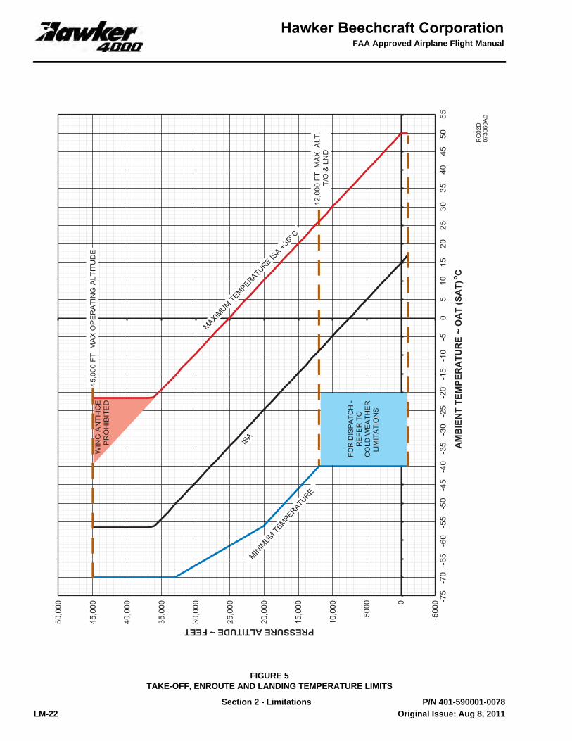
ENROUTE LIMITSMaximum Operating Altitude . . . . . . . . . . . . . . . . . . . . . . . . . . . . . . . . . . . . . . . . . . . . . . . . . . . . . . . . . . . . . . . . . . . . 45,000 FTMaximum Fuel Imbalance. . . . . . . . . . . . . . . . . . . . . . . . . . . . . . . . . . . . . . . . . . . . . . . . . . . . . . . . . . . . . . . . . . 500 LB (227 KG)Ambient Air Temperature . . . . . . . . . . . . . . . . . . . . . . . . . . . . . . . . . . . . . . . . . . . . . . . . . . . . . . . . . . . . . . . . . Refer To Figure 5Opening the interior baggage door above 35,000 FT is prohibited unless directed by an Emergency or Abnormal Procedure.Pilot’s and Copilot’s outboard armrests must be up and stowed for operations at 25,000 FT and above.
Original Issue: Aug 8, 2011
FAA Approved Airplane Flight Manual
Section 2 - LimitationsLM-22 P/N 401-590001-0078
FIGURE 5TAKE-OFF, ENROUTE AND LANDING TEMPERATURE LIMITS
40,0
00
45,0
00
50,0
00
-500
00
5000
10,0
00
15,0
00
20,0
00
25,0
00
30,0
00
35,0
00
-75
-70
-65
-60
-55
-50
-45
-40
-35
-30
-25
-20
-15
-10
-50
510
1520
2530
3540
4550
55
12,0
00 F
T M
AX
ALT
. T/
O &
LN
D
45,0
00 F
T M
AX
OP
ER
ATI
NG
ALT
ITU
DE
FOR
DIS
PA
TCH
-R
EFE
R T
OC
OLD
WE
ATH
ER
LIM
ITA
TIO
NS
WIN
G A
NTI
-ICE
PR
OH
IBIT
ED
Original Issue: Aug 8, 2011

Section 2 - Limitations
FAA Approved Airplane Flight Manual
LM-23 P/N 401-590001-0078
OCCUPANCY LIMITSMinimum Flight Crew . . . . . . . . . . . . . . . . . . . . . . . . . . . . . . . . . . . . . . . . . . . . . . . . . . . . . . . . . . . . . . . . . . 1 Pilot and 1 CopilotMaximum Passengers . . . . . . . . . . . . . . . . . . . . . . . . . . . . . . . . . . . . . . . . . . . . . . . . . . . . . . . . . . . . . . . . . . . . . . . . . . . . . . . .10
AVIONICS SYSTEM LIMITS
GENERAL1. The following publications contain the description and operation of the Primus EPIC avionics and integrated FMS,
EGPWS and TCAS systems and must be carried onboard the airplane at all times:• Primus EPIC Pilot’s Manual For the Hawker Horizon, Pub No. A28-1146-154-00, or later applicable revision.• Flight Management System (FMS) for the Primus EPIC Hawker Horizon Software Version NZ 7.01 Pilot’s Guide, Pub
No. A28-1146-190-02, or later applicable revision.• ACSS TCAS 2000/3000 Pilot’s Guide, Pub No. 8006773-001, or later applicable revision.• Enhanced Ground Proximity Warning System (EGPWS) and Flight Safety Functions TSO C151b Class A TAWS,
Pilot’s Guide, Pub No. 060-4241-000, Rev G or later applicable revision.2. Minimum Equipment. The following avionic equipment must be operational prior to takeoff: Air Data Computers (ADC 1
and ADC 2), Inertial Reference Systems (IRS 1 and IRS 2), 2 PFDs, one MFD, EICAS, both MCDUs, both CCDs,Display Controllers and Flight Guidance Panel.
STANDBY INSTRUMENT1. When using the Standby Instrument as the only source of airspeed information, the red airspeed warning on the Standby
Instrument must not be exceeded.2. The Standby Instrument must be operational for takeoff.
FLIGHT MANAGEMENT SYSTEM (FMS)1. Direct-Previous and Present Position Hold operations are prohibited whenever the airplane is already established in the
missed approach segment of an FMS flight plan.2. Instrument Flight Rules (IFR) enroute and terminal navigation is prohibited unless the Pilot verifies either the currency of
the database or the accuracy of each selected waypoint and NAVAID by reference to current approved data.3. If an FMS has been degraded down to Dead Reckoning (DR) mode, that FMS shall not be used for navigation.4. Use of FMS to capture and track a Distance Measuring Equipment (DME) arc outside the published end points is
prohibited.5. Activating a Hold operation is prohibited while in vertical path (VPTH) mode.6. Activating vectors during a non-LPV FMS approach may result in below-glide path VGP indications at the FAF. The crew
must monitor VGP indications during glide path capture and execute a missed approach if VGP indications are notconsistent with normal glide path capture.
VNAV1. When using the VNAV system, the barometric altimeters must be used as the primary altitude reference for all
operations.2. VNAV altitudes must be displayed on the Multifunction Control Display Unit (MCDU) active Flight Plan page when
utilizing VPTH mode for vertical flight guidance.3. Use of VNAV vertical guidance is prohibited when the barometric altitude is corrected to the landing field elevation (QFE
OPERATION).4. Vertical direct to the FAF operations are prohibited when conducting VGP or LPV approaches.
Original Issue: Aug 8, 2011

FAA Approved Airplane Flight Manual
Section 2 - LimitationsLM-24 P/N 401-590001-0078
TOLD (TAKE-OFF AND LANDING DATA)1. The FMS TOLD computed VSPEEDS and distances must be checked for reasonableness. The AFM or other
FAA-approved documents must be available for reference as necessary.2. To use the FMS TOLD function for takeoff when the barometric altitude is corrected to the landing field elevation (QFE),
the actual barometric setting (QNH) must be manually entered in the Takeoff Initialization pages by the crew.3. Use of the FMS TOLD landing distance information is prohibited when the barometric altitude is corrected to the landing
field elevation (QFE).4. Use of the FMS TOLD function is prohibited when operating on contaminated runways.
APPROACH1. FMS-based Instrument approaches must be accomplished in accordance with approved instrument approach
procedures that are retrieved from Honeywell EPIC FMS Navigation Data Base (NDB).• Accomplishment of Instrument Landing System (ILS), Localizer (LOC), LOC-BC, LDA and SDF approaches are not
authorized utilizing the FMS as the primary navigation source.
NOTENot all published approaches are in the FMS or Charts/Maps databases. The flight crew must ensurethat the planned approach is in the database.
2. The FMS approach annunciator (green APP on the PFD) must be illuminated when crossing the FAF in order to conductthe approach procedure.
3. In order to use LPV approach minima, the LPV green annunciator must be illuminated on the PFD being used for primarynavigation when crossing the FAF.
4. The flight crew must verify the active navigation source is LOC or BC prior to crossing the FAF for ILS, LOC, BC, LDA,and SDF approach procedures.
REQUIRED NAVIGATION PERFORMANCE (RNP)1. The Model 4000 is capable of RNP 0.3 operations when required operational approvals have been obtained.2. The navigation map must be displayed on at least one MFD during RNAV (RNP) approach procedures.3. For RNAV (RNP) approach procedures with missed approach RNP of 1.0, a missed approach must be initiated if both
PFD messages post (MCDU UNABLE RNP message).4. For RNAV (RNP) approach procedures with missed approach RNP less than 1.0, a missed approach must be initiated if
either PFD message posts (MCDU UNABLE RNP message).5. FD or AP must be in LNAV mode during RF legs.6. When conducting a missed approach from an RNAV (RNP) approach procedure, the FD LNAV mode must be utilized
before climbing above 400 FT AGL7. Prior to the IAF, updating from VOR/DME 1 and 2 must be disabled on FMS 1 and 2.
VOR1. Do not use VOR / DME function while “EE” or “EEEE” is displayed as identifier.
AUTOPILOT (AP)1. During AP operations, a Pilot must be seated at the controls with seat belt and shoulder harness fastened.2. Maximum speed with AP engaged in FLC mode in climb and descent must not exceed 0.82M.3. Use of the AP when in Short Range NAV (SRN) for VOR Approaches is limited to the use of HDG only. Do not couple to
the VOR.4. Use of the AP below 80 FT above ground level (AGL) for approach operations and 400 FT AGL for all other operations is
prohibited.
DGRAD
DGRAD
Original Issue: Aug 8, 2011


FAA Approved Airplane Flight Manual
Section 2 - Limitations2 of 4 401-590001-0078TC11
Beechcraft Corporation
THIS PAGE INTENTIONALLY LEFT BLANK
Revision 1: Jun 16, 2016

Section 2 - Limitations
FAA Approved Airplane Flight Manual
LM-25 P/N 401-590001-0078
FLIGHT DIRECTOR (FD)1. Use of the FD when in Short Range NAV (SRN) for VOR Approaches is limited to the use of HDG only. Do not couple to
the VOR.2. Maximum speed with FD engaged in FLC mode in climb and descent must not exceed 0.82M.
AUTOTHROTTLE (A/T)1. A/T must be disengaged by 100 FT AGL prior to landing.2. For A/T coupled approach, the minimum selected speed must be normal approach speed plus 3 KIAS.
ELECTRONIC CHARTS1. The airplane position displayed on the electronic charts is not to be used for primary navigation.
VERTICAL PROFILE1. Selection of the Vertical Profile display is prohibited.
TAWS
NOTEThe terrain database, displays and alerting algorithms currently account for limited catalogued human-made obstructions in North America and Europe. If obstacle data is not in the database for a particularobstacle, the Obstacle Awareness alerting is not available for that obstacle.
1. Navigation must not be predicated upon the use of the TAWS. The Terrain Display is intended to serve as a situationalawareness tool only and may not provide the accuracy and / or fidelity on which to solely base terrain avoidancemaneuvering.
2. Pilots are authorized to deviate from their current Air Traffic Control (ATC) clearance to the extent necessary to complywith an EGPWS warning.
3. When the FMS is operating in the DR mode, the Terrain Awareness alerting must be inhibited by selecting the TERRAININHIBIT switch.
TCAS II1. Pilots are authorized to deviate from their current ATC clearance to the extent necessary to comply with a TCAS II
resolution advisory (RA).2. If ATC requires the transponder altitude reporting to be disabled, TCAS must be turned off.3. Maneuvers based solely on a traffic advisory (TA) or on information displayed on the traffic display are not authorized.
SYNOPTIC DISPLAYS1. CAS MSGs have priority over Synoptic Display as source for system status except as otherwise stated.2. The Elec Synoptic Display is not to be used for Emergency Windshield Heat information.3. The following Synoptic information must be available for flight:
a. ECS Synoptic.b. Bleed Synoptic.c. Elec Synoptic.d. Fuel temperature indication on Fuel Synoptic as specified under Fuel Temperature Limits.e. Flt Ctl Synoptic.f. Hydraulic temperature and quantity indication on Hyd Synoptic.
Original Issue: Aug 8, 2011

FAA Approved Airplane Flight Manual
Section 2 - LimitationsLM-26 P/N 401-590001-0078
MODE S ENHANCED SURVEILLANCE TRANSPONDER (IF INSTALLED)The installed Mode S system satisfies the data requirements of the International Civil Aviation Organization (ICAO) Doc. 7030/4, Regional Supplementary Procedures for SSR Mode S Enhanced Surveillance in designated European airspace.
The capability to transmit data parameters is designated as follows:
AFCS must be coupled to the operative side ADC for Emergency and Abnormal Procedures that require an ADC reversion.
HOT WEATHER LIMITATIONS1. Maximum temperature for single PACK dispatch is 38° C (100° F).2. At OATs above 44° C (112° F), ground operation using external DC or AC power, or the APU generator, is limited to 5
minutes unless both PACKS are on.3. At OATs above 44° C (112° F), ground operation with HF powered, is limited to 25 minutes.
a. For ground operation exceeding 25 minutes under these limitations, the HF COM 1 ANT and HF COM 2 ANT (ifinstalled) CBs, must be OUT.
NOTETo restore HF operation, after resetting CBs, refer to SECTION 4 - NORMAL PROCEDURES - HFOPERATION.
Parameter Available
Magnetic Heading Yes
Indicated Airspeed Yes
Mach Number Yes
Vertical Rate Yes
Roll Angle Yes
Track Angle Rate No
True Airspeed (If Track Angle Rate is not available)
Yes
True Track Angle Yes
Groundspeed Yes
Selected Altitude Yes
Barometric Pressure Setting Yes
Original Issue: Aug 8, 2011
Section 2 - Limitations
FAA Approved Airplane Flight Manual
LM-27 P/N 401-590001-0078
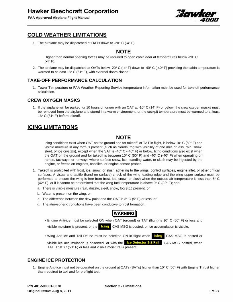
COLD WEATHER LIMITATIONS1. The airplane may be dispatched at OATs down to -20° C (-4° F).
NOTEHigher than normal opening forces may be required to open cabin door at temperatures below -20° C(-4° F).
2. The airplane may be dispatched at OATs below -20° C (-4° F) down to -40° C (-40° F) providing the cabin temperature iswarmed to at least 16° C (61° F), with external doors closed.
TAKE-OFF PERFORMANCE CALCULATION1. Tower Temperature or FAA Weather Reporting Service temperature information must be used for take-off performance
calculation.
CREW OXYGEN MASKS1. If the airplane will be parked for 10 hours or longer with an OAT at -10° C (14° F) or below, the crew oxygen masks must
be removed from the airplane and stored in a warm environment, or the cockpit temperature must be warmed to at least16° C (61° F) before takeoff.
ICING LIMITATIONS
NOTEIcing conditions exist when OAT on the ground and for takeoff, or TAT in flight, is below 10° C (50° F) andvisible moisture in any form is present (such as clouds, fog with visibility of one mile or less, rain, snow,sleet, or ice crystals), except when the SAT is -40° C (-40° F) or below. Icing conditions also exist whenthe OAT on the ground and for takeoff is between 10° C (50° F) and -40° C (-40° F) when operating onramps, taxiways, or runways where surface snow, ice, standing water, or slush may be ingested by theengine, or freeze on engines, nacelles, or engine sensor probes.
1. Takeoff is prohibited with frost, ice, snow, or slush adhering to the wings, control surfaces, engine inlet, or other criticalsurfaces. A visual and tactile (hand on surface) check of the wing leading edge and the wing upper surface must beperformed to ensure the wing is free from frost, ice, snow, or slush when the outside air temperature is less than 6° C(42° F), or if it cannot be determined that the wing fuel temperature is above 0° C (32° F); anda. There is visible moisture (rain, drizzle, sleet, snow, fog etc.) present; orb. Water is present on the wing; orc. The difference between the dew point and the OAT is 3° C (5° F) or less; ord. The atmospheric conditions have been conducive to frost formation.
• Engine Anti-ice must be selected ON when OAT (ground) or TAT (flight) is 10° C (50° F) or less and
visible moisture is present, or the CAS MSG is posted, or ice accumulation is visible.
• Wing Anti-ice and Tail De-ice must be selected ON in flight when CAS MSG is posted or
visible ice accumulation is observed, or with the CAS MSG posted, whenTAT is 10° C (50° F) or less and visible moisture is present.
ENGINE ICE PROTECTION1. Engine Anti-ice must not be operated on the ground at OATs (SATs) higher than 10° C (50° F) with Engine Thrust higher
than required to taxi and for preflight test.
Icing
Icing
Ice Detector 1-2 Fail
Original Issue: Aug 8, 2011

FAA Approved Airplane Flight Manual
Section 2 - LimitationsLM-28 P/N 401-590001-0078
TAIL DE-ICE OPERATION1. Maximum OAT (SAT) on ground, and TAT in flight, to operate Tail De-ice is 10° C (50° F).2. Continuous operation on the ground, with flap positions greater than 12°, is limited to 10 minutes ON, 5 minutes OFF
cycles.3. Continuous operation in flight, with flap positions greater than 12°, is limited to 30 minutes ON, 1 minute OFF cycles.
WING ANTI-ICE OPERATION1. Maximum OAT (SAT) on ground and TAT in flight to operate Wing Anti-ice is 10° C (50° F).2. Use of Wing Anti-ice is prohibited above the temperatures illustrated in Figure 5.3. Time with Wing Anti-ice ON, and thrust settings higher than idle while stationary on ground, must not exceed 10
seconds.4. Both engine bleeds must be operative for dispatch into known icing.5. Wing Anti-ice operation must be terminated if the following CAS MSGs are posted:
a.
b.
c.
AIRSPEED LIMITS1. Minimum airspeed for sustained flight in icing (except for takeoff, approach, and landing) is 190 KIAS up to 37,000 LB
(16,783 KG).2. Minimum airspeed for sustained flight in icing (except for takeoff, approach, and landing) is 200 KIAS above 37,000 LB
(16,783 KG).
FLAP OPERATION1. Operating the airplane in icing, at other than flaps UP, for an extended period of time (except takeoff, approach, and
landing) is prohibited.
SEVERE ICING / FREEZING RAIN CONDITIONS
Severe icing / freezing rain may result from environmental conditions outside of those for which theairplane is certified. Flight in freezing rain, freezing drizzle, or mixed icing conditions (supercooled liquidwater and ice crystals) may result in ice build-up on protected surfaces exceeding the capability of the IceProtection Systems, or may result in ice forming aft of the protected surfaces. This ice may not be shedusing the Ice Protection Systems, and may seriously degrade the performance and controllability of theairplane.
During flight, severe icing / freezing rain conditions that exceed those for which the airplane is certifiedshall be determined by the following visual cues.
If one or more of these visual cues exists, accompanied by the “icing” annunciations, immediatelyrequest priority handling from Air Traffic Control to facilitate a route or an altitude change to exit the icingconditions:
• Extensive ice accumulations on the airframe in areas not normally observed to collect ice.• Accumulation of ice on the wing aft of the protected surface.• Flowing water or melting ice on the windshield.
Since the autopilot may mask tactile cues that indicate adverse changes in handling characteristics, useof the autopilot is prohibited in icing conditions when any of the visual cues specified above exist, orwhen unusual lateral trim requirements or autopilot mistrim amber CAS MSGs are encountered.
Wing A-Ice Temp High
Wing Bleed Leak
Wing A-Ice Ovpress
Original Issue: Aug 8, 2011
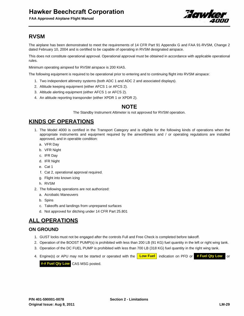
Section 2 - Limitations
FAA Approved Airplane Flight Manual
LM-29 P/N 401-590001-0078
RVSMThe airplane has been demonstrated to meet the requirements of 14 CFR Part 91 Appendix G and FAA 91-RVSM, Change 2dated February 10, 2004 and is certified to be capable of operating in RVSM designated airspace.
This does not constitute operational approval. Operational approval must be obtained in accordance with applicable operationalrules.
Minimum operating airspeed for RVSM airspace is 200 KIAS.
The following equipment is required to be operational prior to entering and to continuing flight into RVSM airspace:
1. Two independent altimetry systems (both ADC 1 and ADC 2 and associated displays).2. Altitude keeping equipment (either AFCS 1 or AFCS 2).3. Altitude alerting equipment (either AFCS 1 or AFCS 2).4. An altitude reporting transponder (either XPDR 1 or XPDR 2).
NOTEThe Standby Instrument Altimeter is not approved for RVSM operation.
KINDS OF OPERATIONS1. The Model 4000 is certified in the Transport Category and is eligible for the following kinds of operations when the
appropriate instruments and equipment required by the airworthiness and / or operating regulations are installedapproved, and in operable condition:a. VFR Dayb. VFR Nightc. IFR Dayd. IFR Nighte. Cat 1f. Cat 2, operational approval required.
g. Flight into known icingh. RVSM
2. The following operations are not authorized:a. Acrobatic Maneuversb. Spinsc. Takeoffs and landings from unprepared surfacesd. Not approved for ditching under 14 CFR Part 25.801
ALL OPERATIONS ON GROUND
1. GUST locks must not be engaged after the controls Full and Free Check is completed before takeoff.2. Operation of the BOOST PUMP(s) is prohibited with less than 200 LB (91 KG) fuel quantity in the left or right wing tank.3. Operation of the DC FUEL PUMP is prohibited with less than 700 LB (318 KG) fuel quantity in the right wing tank.
4. Engine(s) or APU may not be started or operated with the indication on PFD or or
CAS MSG posted.
Low Fuel # Fuel Qty Low
#-# Fuel Qty Low
Original Issue: Aug 8, 2011

FAA Approved Airplane Flight Manual
Section 2 - LimitationsLM-30 P/N 401-590001-0078
PASSENGER SAFETY BRIEFING1. Passenger Briefing Cards must be available for use by each passenger and contain the following information: Diagram
on how to operate Emergency Exits, Exit Procedures, Water Barrier Installation Procedures, Life Vest Procedures, Lossof Cabin Pressure Procedures, Smoking Procedures, Seat belt Procedures, Location of Survival Equipment and otherinstructions necessary for the use of Emergency Equipment.
2. Aural Briefing must contain: Required compliance with lighted passenger information signs and crew memberinstructions, Emergency Exits, Exit Procedures, Water Barrier Installation Procedures, Life Vest Procedures, Loss ofCabin Pressure Procedures, Smoking Procedures, Seat belt Procedures, Location of Survival Equipment and otherinstructions necessary for the use of Emergency Equipment.
FIRE EXTINGUISHER EQUIPMENT1. The cockpit and cabin extinguishers must have a total minimum quantity of 13 LB (6 KG) of Halon 1211 fire extinguisher
agent (or equivalent).2. The fire extinguishers in cockpit and cabin must be accessible to the Flight Crew.
HEADSETS1. Pilot and Copilot are required to have headsets readily available in cockpit.2. Pilot and/or Copilot must wear headset when respective FLT DECK SPEAKER switch (if installed) indicates OFF.
OXYGEN MASKSCREW
1. It must be ensured that the crew oxygen masks can be donned quickly and fit properly. Large eyeglasses, headsets andhats may need to be removed before donning oxygen masks.
2. Maximum safe cabin altitude for sustained use of crew oxygen masks is 40,000 FT.
PASSENGER1. Maximum safe cabin altitude for sustained use of passenger oxygen masks is 25,000 FT.
WATER BARRIER1. Water barrier must be onboard for all flights.
TOILET SEAT1. The toilet seat must not be occupied during takeoff and landing unless the belted toilet seat (option) is installed.
Original Issue: Aug 8, 2011