section 16940 instrumentation and field devices …public.eandm.com/muni_docs/bigsur.pdf · section...
TRANSCRIPT

SECTION 16940INSTRUMENTATION AND FIELD DEVICES
PART 1 - GENERAL
1 .1 SCOPE OF WORK
A. Provide all devices, wiring, terminal blocks, accessories, and enclosures asspecified herein and as shown on Contract Drawings for the instrumentationsystem. The Contract Documents are intended as an outline for the work andare descriptive of the type of hardware and software configuration to beprovided. Any error or omission of detail shall not relieve the Contractor fromthe obligations hereunder to provide and install in correct detail any and allmaterials necessary for a complete operational instrumentation system, at noadditional cost to the State.
B. The major areas in the scope of work which includes both the furnishing andinstallation are:
1. Provide/install instrumentation system as shown and specified herein andin Division 16.
2. Instrumentation devices such as level elements (LE), pressure indicators(PI), pressure indicating transmitters (PIT), flow elements (FE), may not beshown on Mechanical Drawings. All instrumentation devices shall beprovided and installed by the Contractor at the locations in the process asshown on the Contract Drawings. It is the Contractor's responsibility toinstall all new and relocated instruments per manufacturer's installationrequirements even if not specifically shown on the Contract Drawings.
3. All necessary piping and valves to have complete installation.
C. The Contract Documents are not intended to cover every detail of materials,software, hardware, configuration, or construction. The Contractor shall furnishall tools, temporary utilities, materials, setup, parts, labor, and other incidentalsnecessary to fully complete the entire work, whether or not said details areparticularly shown or specified, all at no additional cost to the State.
D. Ranges for instruments shall be as shown on in Appendix B or CInstrumentation and Field Devices Index or as marked-up during Submittal.Process setpoints will be provided by State during Submittal process, testing,and startup.
E. All equipment, hardware, and software shall be licensed to the State.
F. All necessary miscellaneous shut off, sample, and calibration valves to sensors.

Section 16940- Page 2Instrumentation and Field Devices
G. Provide all necessary hardware, conduit, wiring, fittings, and devices to connectthe electrical equipment provided under other Sections. The following shall bedone by the Contractor at no additional cost to the State:
1. Provide additional devices, wiring, conduits, relays, isolators to completeinterfaces of the electrical and instrumentation system.
2. Changing normally open contacts to normally closed contacts or viseversa.
3. Adding additional relays to provide more contacts as necessary.
1 .2 SUBMITTALS
A. Manufacturer's literature and installation recommendations for allinstrumentation provided.
B. Schematic (elementary or ladder) diagram and wiring (interconnection) diagramfor each control system.
C. All drawings shall be drawn using AutoCAD, drawn in a professional mannerand submitted on 11" x 17" sheets. Shop drawings shall be provided withminimum drafting details as illustrated on the Contract "electrical" seriesdrawings. Diagrams shall carry a uniform and coordinated set of wire colors,wire numbers, and terminal block numbers. The shop drawings shall include:
1. Electrical one-line diagrams detailing all devices associated with the powerdistribution system. The following applicable information or data shall beshown on the one-line diagram: location, size and amperage rating of bus;size and amperage rating of wire or cable; breaker ratings, number ofpoles, and frame sizes; generator receptacle; manual transfer switch,utility metering, voltage, amperage, number of wires and phases; faultinterrupt ratings; ground size and connections; neutral size andconnections; power fail and other protective devices; fuse size and type;distribution transformer; panelboard; starters; contactor size and overloadrange; motor full load amperage of submitted motor and horsepower;rating for miscellaneous loads; etc. Submit a list for each piece ofequipment containing the motor voltage, phase and full load amps withone-lines for verification of accuracy of submitted one line drawings.
2. Elementary diagrams shall be provided for all relay logic, power supplies,PLC I/O and other wiring. All elementary diagrams shall be drawn in JICEMP/EGP format and standards similar to those shown on the E-serieselementary diagrams showing ladder rung numbers and coil & contactcross referencing numbers.

Section 16940 - Page 3Instrumentation and Field Devices
3. Analog and digital I/O loop diagrams shall be provided showing the wiringrequirements for each instrument loop. Graphic symbols shall conformwith ISA S5.4 drawing standards. A loop diagram shall be furnished foreach analog and digital I/O process and all PLC I/O cards. Loop diagramsshall include the following as a minimum:
a. The loop diagram shall be drawn with sufficient detail to expresscontrol philosophy. The diagram shall show all components andaccessories of the instrument loop, highlighting special safety andother requirements. These diagrams shall be arranged to emphasizedevice elements and their functions as an aid to understanding theoperation of a system and for maintaining or troubleshooting thatsystem.
b. A separate drawing shall be prepared for each analog and digitalcard. Each card shall be arranged on the diagram in the same orderas the physical arrangement of the card terminations. All terminationpoints on the diagram shall be shown with the actual equipmentidentification, device and relay terminal number or letter, and I/Opoint P&ID English descriptor and tag name. A separate drawingshall be prepared for each card.
c. Energy sources - electrical power, air supply, pneumatic andhydraulic fluid supply, designating voltage, current, pressure, etc.shall be shown in detail on the diagram. Input and output signals(e.g., 1-5 VDC, 4-20 mA DC, 3-15 psig, etc.), power and instrumentsupplies to devices (e.g. 120 VAC, 24 VDC, 80 psig, etc.) shall beshown.
d. Engineering units shall be shown on the diagram. Each wire label,equipment identification terminal number or letter and color codeshall be shown. Signal and DC polarities shall be shown.
e. All spare wires, cables and termination points shall be shown. Alljumpers, grounding, shielding, power supply details shall be shown.
4. Enclosure and Elevation layout diagrams for Electrical Panels/Pedestal;show all front panel, sidepan and backpan devices drawn to scale. Showfabrication methods and details; including material of construction, paintcolor, support & latching mechanisms, fans & ventilation system, andconduit entrance areas.

Section 16940- Page 4Instrumentation and Field Devices
5. Interconnection Diagram - An interconnection diagram shall be furnishedfor each electrical and instrumentation system. Each interconnectiondiagram shall include the following as a minimum:
a. The diagrams shall be utilized by the electrician during all phasesinstallation and connection of all conductors to ensure coordinationof equipment interconnect.
b. The diagrams shall show wiring as field labeled.
c. Interconnections shall be shown point to point with identified lines.Diagrams of the wireless or wire schedule type are not acceptable.Bundled wires shall be shown as a single line with the direction ofentry/exit of individual wires clearly shown. Interconnect diagramsshall not be combined with loop or elementary diagrams.
d. All terminations points on the diagram shall be shown with the actualequipment identification terminal number or letter. This identificationof terminations includes terminal blocks, junction boxes, all devices,computer I/O points, etc.
e. Diagrams shall include raceway numbers, raceway size, cablenumbers, wire color code, and wire numbers.
f. Each wire and cable size and color code shall be shown. Eachconduit route with the conduit label and conduit size shall be shown.Wire and cable routing through conduits, wireways, manholes,handholes, junction boxes, terminal boxes and other electricalenclosures shall be shown with the appropriate equipment labels. Allspare wires, cable, and termination points shall be shown. Cableshields shall be shown.
g. Labeling codes for terminal blocks, terminals, wires, cables, panels,cabinets, instruments, devices, and equipment shall be shown.
h. Schematic symbols shall be used for field devices, showing electricalcontacts. Signal and DC circuit polarities shall be shown.
i. The diagrams shall show all other Contract and supplier drawingnumbers, for reference, that are associated with each device that isinterconnected.
j. Field wiring shall not start before the interconnection drawing havebeen submitted by the Contractor and approved by the Staterepresentative.

Section 16940 - Page 5Instrumentation and Field Devices
k. Do not show the same wires or jumpers on the elementary or loopand interconnection diagrams. All jumpers, shielding, and groundingtermination details not shown on the connection diagrams shall beshown on the interconnection diagrams.
Interconnection diagrams shall be submitted and approved by Staterepresentative for each electrical and instrumentation system. TheContractor shall not pull in any wires into conduits that does not haveapproved interconnects. If the Contractor pulls in wire without Staterepresentative approval of associated interconnect drawings, theContractor will not be reimbursed for labor for re-pulling in wires evenif there was an error in wire fill or sizing. Also, if the Contractor pullsin wire without State representative approval of associatedinterconnect drawings, then all progress payments for that particulararea of work will be withheld until approved interconnect drawingsare in use.
m. The diagrams shall show all other Contract and Supplier drawingnumbers, for reference, that are associated with each device that isinterconnected. Attached with each interconnect, a copy of all thesupport documents used in preparing interconnects. This includescurrent issues of panel schematics, connection diagrams, terminalblock diagrams, submittals, contract drawings, vendor drawings andall other data used to develop the interconnection diagram as notedin the "Reference Documents" corner of interconnect drawings.
n. All interconnection diagrams shall be prepared and checked by aCalifornia Registered Electrical Engineer and shall bear thatEngineer's professional stamp and signature on each and everyinterconnect drawing submitted for approval and on as-builtinterconnect drawings. All deletions and additions of equipment,wire and cables shall be clearly shown. Interconnects shall includelist of all applicable reference drawings, request for clarifications,field instructions and change orders.
o. Provide a notes section on each interconnect drawing. In the notesection, provide a detailed list of any variances from the Contractconduit schedule necessary for completing the interconnections (i.e.wire fill changes, conduit additions, etc). Change orders regardingwire fill, conduit schedule and errors in plans regarding conduits andwires may not be processed until interconnect drawings have beenreceived for such work.

Section 16940- Page 6Instrumentation and Field Devices
p. The field electrician shall mark-up all interconnection diagramsduring installation to show accurate as-built wiring, conduits runs,terminations, etc.
6. Submit full size drawing of all nameplates and tags, as specified herein, tobe used on project. The State's Representative has the right to adjustnameplate engraving titles during submittals at no additional cost to theState representative. Submittal to include the following:
a. Dimensions of nameplate.
b. Exact lettering and font for each nameplate.
c. Color of nameplate.
d. Color of lettering.
e. Materials of construction.
f. Method and materials for attachment.
g. Drawing showing location of nameplate on each panel.
D. Provide the following three separate processor programmable controller (PLC)applications programming software and SCADA graphics submittals for eachprocessor program:
1 . Preliminary Submittal - PLC & SCADA hardware and softwareconfiguration shall be submitted at 10 percent complete level for apreliminary courtesy check by the Contracting Officer or State'sRepresentative. This check will not entail a detailed check of allperformance features and will not absolve the Contractor of his Contractresponsibilities. It is required that the PLC & SCADA applications softwarebe fully annotated with complete description of control logic, explanation ofsymbology, and convention including legend list.
2. Formal Submittal - This is the submittal for review per ContractRequirements and is to be submitted after approval by Contracting Officeror State's Representative of the preliminary submittal. This submittal shallbe approved for basic content (not for correctness of ladder logic code) byContracting Officer or State's Representative prior to start of any PLC &SCADA factory tests.
3. Final Submittal - This submittal will be part of 0 & M manual. Thesoftware documentation shall be the as-finished records of the formalsubmittal and other documents used during testing and startup. Three (3)weeks (minimum) prior to the start of the factory tests, the Contractor shallsubmit for approval the following software information:

Section 16940 - Page 7Instrumentation and Field Devices
E. Three (3) weeks (minimum) prior to the start of the factory tests, the Contractorshall submit for approval the following software information:
1. Submit PLC software submittal showing the structure of the applicationsprograms and the purpose of each module.
a. English description, flowchart, and index of each major ladder logicprogram section illustrating subsection of program organization.
b. Include high level block diagram and English description of PLC filestructure.
c. Include comments for each block of code explaining purpose ofindividual lines.
d. Include a listing of all setpoints with their corresponding Englishdescription.
e. Manual shall include complete explanation on the set-up andconfiguration of the PLC hardware and software.
f. Include a description of the PLC diagnostic and Ladder Logicprogramming functions available through the diagnostic computer.
2. PLC software submittal documentation shall include machine printedladder diagrams and listings. This documentation shall detail the following:
a. The ladder diagrams shall be drawn with the contacts on the left sideof the coil on each rung. Each contact and coil shall have a typeddescription of its function. A line-by-line typewritten description of theeach rung shall be given on the ladder diagrams. Each I/O point inthe ladder logic shall be shown with it's corresponding I/O "tagname";i.e. Y1001 for digital input of Disk Filter Isolation Weir GateRemote/Local switch.
b. An "Input/Output List," tabulating the module location, terminalpoints, channel number, address number, point type, point voltage,input/output designation "nickname" and/or number, and a textualdescription for each item of input and output.
c. A "Constant Memory Assignment List," tabulating the assignedregister name, location number, and textual description for eachconstant stored in memory.
d. A "Variable Memory Assignment List," tabulating the assignedregister name, location number, and textual description for eachvariable stored in memory.

Section 16940- Page 8Instrumentation and Field Devices
e. A "Cross Reference List," tabulating the rung locations for the usageof each symbol throughout the ladder logic. For each coil, the runglocations for each of its contacts shall be listed. For each input allthe rungs in the ladder logic in which it is used shall be listed.
f. A "Memory Map and Usage List," tabulating the allocation of CPUmemory. This listing shall identify the contents of the reservedmemory and what areas are unused.
g. A brief description on a page preceding the ladder diagram listings,describing all symbols and functions used on the ladder diagram.
h. A written description of lookup table data, for each lookup table.Include the source of data used for each table.
i. A brief description, on each page of "Special Function" listings,including:
1 ) A textual description of input variables and/or constants.
2) A textual description of output variables and/or constants.
3) A textual description of the functions.
4) Reference(s) to any specific locations on the ladder diagramlistings where the special functions apply.
3. Submittal content shall comply with the following:
a. Contain complete and separate data files shall be provided for eachPLC applications program.
b. Applications program files shall be capable of being uploaded fromthe PLC and separate comment files shall be capable of beingmerged with the code for program maintenance.
c. Program files shall be stored in a format that can be retrieved,edited, merged with comment files, and downloaded to PLC usingthe programming software.
d. Listing of all setpoints with proposed initial numeric entry values andcorresponding Engineering Units for control strategies. Submitspreadsheet style setpoint list for all pressure, flow, level, timers, etc.
e. Listing of all digital and analog registers, bits, timers etc., theirrespective description, I/0 tagnames, and full addresses fordevelopment of factory test screen.

Section 16940 - Page 9
Instrumentation and Field Devices
f. Complete commented ladder logic program.
g. Map all analog and digital inputs/outputs including spares to B, F, orN registers.
h. Transfer all data between PLCs, SLCs, and Chem Scan units for acomplete and operable system.
4. Submittal of color printout of all SCADA graphic screens proposed andtheir associated database.
5. Submit software documentation demonstrating understanding of controlsoftware requirements.
6. The Contractor shall submit for approval the resume of the applicationprogrammer listing all relevant experience. Application programmer thatdoes not have relevant experience to this project will be rejected byContracting Officer or State's Representative and the Contractor shallsubmit the resume of a qualified application programmer.
F. Submittals shall be placed in three ring binders with complete index of contentsand all drawings (place in front of other submittal material). All copies shall beclear and legible. Data sheets shall be provided for each instrument with anindex and proper identification and cross-referencing. Each drawing title blockshall contain the English description name for drawing contents (i.e. Lift PumpNo. 1 Interconnect Drawing) and drawing number. All pages and drawings inthe submittal shall be numbered sequentially (with no number skipped) in lowerright hand corner. PLC Data files shall be provided with an index and properidentification and cross-referencing.
G. Exceptions to the Contract specifications, control strategies or drawings shall beclearly defined by the equipment supplier. Data shall contain sufficient details soa proper evaluation may be made by the State's Representative. Request forinformation (RFIs) shall not be included in submittals. RFI's shall be submittedseparately in its individual submittal number.
H. The Supplier shall coordinate submittals (including software submittals) with thework so that project will not be delayed. This coordination shall includescheduling the different categories of submittals, so that one will not be delayedfor lack of coordination with another.
No material, equipment, or software shall be allowed at the job site until thesubmittal for such items has been favorably reviewed by the State'sRepresentative and marked "No Exceptions Taken" or "Make CorrectionsNoted".

Section 16940- Page 10Instrumentation and Field Devices
J. The equipment specifications have prepared on the basis of the equipment firstnamed in the Specifications. The Supplier shall note that the second namedequipment, if given, is considered acceptable and equal equipment, but in somecases additional design, options, or modifications may be required, at noadditional cost, to meet Specifications.
K. The decision of the State's Representative governs what is acceptable as asubstitution. If the State's Representative considers it necessary, tests todetermine equality of the proposed substitution shall be made, at the Supplier'sexpense, by an unbiased laboratory satisfactory to the State's Representative.
1 .3 CLOSEOUT SUBMITTALS
A. Operation and maintenance data for review and approval.
1. Manufacturer's operation and maintenance data for instrumentation.
1 .4 QUALITY ASSURANCE
A. Worker's Qualifications: All electrical work shall be performed by licensedelectricians or under the direct supervision of a licensed electrician.
B. A quality assurance procedure shall be defined and implemented by theContractor or subcontractor supervising instrumentation and control systems.The procedure shall:
1. Require that the project manager schedule and budget for in-house andinter-Contractor checking.
a. Specify qualifications required for engineering and technical personnelin the execution and checking of specific tasks.
b. Identify the responsibilities of the executor and the checker.
c. Provide quality assurance data sheets listing specific tasks and stagesof tasks, with space for the printed names of the executor and checker,and the checker's signature and date.
2. The quality assurance procedure shall form part of the contractualrequirements for subcontractors, and manufacturers or suppliers with unitresponsibility. Quality assurance data sheets shall be submitted to Stateon a weekly basis. Failure of Contractor to provide quality assurance datasheets in a timely manner will stop all progress payment forInstrumentation work.

Section 16940 - Page 11
Instrumentation and Field Devices
PART 2 - PRODUCTS
2.1 CONTROL SYSTEM
A. Control Panel located shall consist of the relay system, and other devices for acomplete and operational system.
2.2 APPLICATIONS PROGRAM
A. PLC & SCADA Software Configuration: The Supplier shall provide the PLC &SCADA completely configured and programmed for the monitoring and controlof the process. The PLC & SCADA shall be setup as defined herein. The PLC &SCADA shall be ready to be placed in operation at the time of factory test. Theprogramming, setup and configuration of the PLC & SCADA shall be done bythe PLC & SCADA supplier. All programming shall be performed by anapplication programmer with prior experience on similar PLC & SCADAprojects. The State reserves the right to judge if the application programmerassigned to this project is adequate for the task. If the programming performedis deemed inadequate by the State's representative, then the supplier shallprovide a qualified application programmer to meet these requirements.
B. The setup details given for the PLC & SCADA are intended as guidelines for thesupplier to use to configure the system. The setup details were prepared withthe available information on the software package and may not be the best wayto accomplish the task. Errors and omissions in these details shall be thesupplier's responsibility to correct, at no additional cost to State. The suppliershall meet the intent of the setup specified, making modifications as necessaryto provide an operational system, at no additional cost to the State.
2.3 MISCELLANEOUS DEVICES
A. Provide terminal blocks, fuses, nameplates, pushbuttons, selector switches,indicating lights, relays and timers as specified in other Sections of Division 16.
B. DC Power Supplies:
1. The DC power supply shall use a "linear" type power conversion."Switching" type power supplies are not acceptable. The 12 & 24 VDC
power supplies shall be capable of providing a minimum amperage asshown on Contract Drawings and not over 50% loaded. Submit loadcalculations of all connected 12VDC & 24VDC loads showing powersupplies are adequately sized.

Section 16940- Page 12Instrumentation and Field Devices
2. The AC input voltage step-down transformer shall have separate andisolated primary and secondary windings. This transformer shall provide aminimum of 3,000 V RMS isolation between the input & ground and input& output. The negative output of the power supply shall be grounded tochassis. Short circuit and overload protection shall be provided byelectronic current limiting and foldback with automatic recovery. Automaticremote voltage sensing and adjustment shall be a standard off the shelfpart of the power supply. A manual output voltage adjustmentpotentiometer shall be provided on each power supply.
3. All power supplies shall be U.L. recognized. Power supply shall bePower-One "International Series Linear", Sola, or approved equal.
C. Each isolator shall provide complete isolation of the 4-20 mA output signal fromthe input signal and isolator power supply. Each isolator shall have all solidstate circuitry mounted in a plug-in module. The 4-20 mA output signal shall becapable of driving a 600 ohm load. Accuracy shall be +/- 0.25% of span. Theisolator shall be powered as shown on Contract Drawings. Each isolator shallhave a seven year warranty. The isolators shall be as manufactured by AGMElectronics, Action Instruments, or approved equal.
2.4 ULTRASONIC LEVEL TRANSMITTER
A. Each ultrasonic level indicating transmitter shall be a microprocessor basedecho-time ultra-sonic type providing an electrical level output signal proportionalto the measured level.
B. Provide ultrasonic level elements with level indicating transmitters. Use thefollowing models, or approved equal.
1. Level (Differential) Indicating Milltronics HydroRanger Transmitter (LIT orLDIT): 200, Danfoss Sonolev, orapproved equal.
2. Level Element (LE) Transducer: To match LIT.
C. Provide Level indicating transmitter (LIT) / signal converters meeting thefollowing requirements:
1. Power Supply: Per device index.
2. Measurement Range: 1 to 33 feet.
3. Discrete Outputs: 5 relay outputs-SPDT contacts rated5A/250 VAC; keypad functionprogrammable.
4. Analog Output: Current-isolated 4 to 20mA into 1000 ohmsmax.
Section 16940 - Page 13Instrumentation and Field Devices
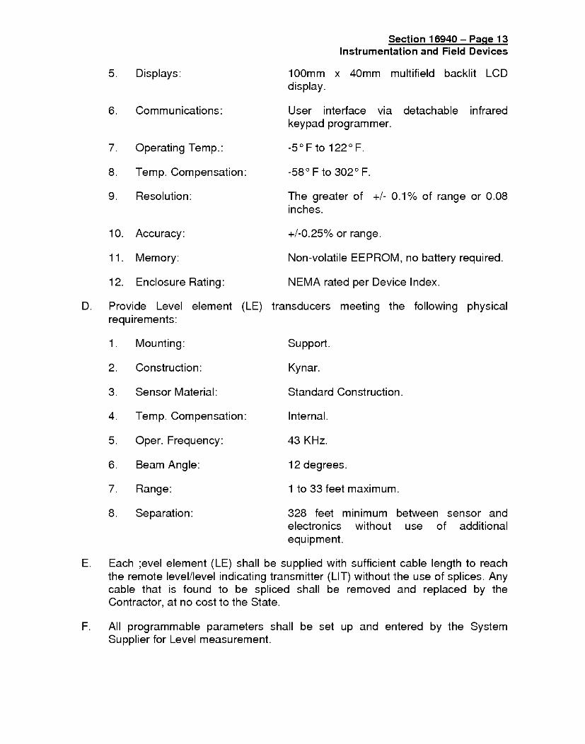
5. Displays: 100mm x 40mm multifield backlit LCDdisplay.
6. Communications: User interface via detachable infraredkeypad programmer.
7. Operating Temp.: -50 F to 122 0 F.
8. Temp. Compensation: -580 F to 3020 F.
9. Resolution: The greater of +/- 0.1% of range or 0.08inches.
10. Accuracy: +/-0.25% or range.
11. Memory: Non-volatile EEPROM, no battery required.
12. Enclosure Rating: NEMA rated per Device Index.
D. Provide Level element (LE) transducers meeting the following physicalrequirements:
1. Mounting: Support.
2. Construction: Kynar.
3. Sensor Material: Standard Construction.
4. Temp. Compensation: Internal.
5. Oper. Frequency: 43 KHz.
6. Beam Angle: 12 degrees.
7. Range: 1 to 33 feet maximum.
8. Separation: 328 feet minimum between sensor andelectronics without use of additionalequipment.
E. Each ;evel element (LE) shall be supplied with sufficient cable length to reachthe remote level/level indicating transmitter (LIT) without the use of splices. Anycable that is found to be spliced shall be removed and replaced by theContractor, at no cost to the State.
F. All programmable parameters shall be set up and entered by the SystemSupplier for Level measurement.

Section 16940- Page 14
Instrumentation and Field Devices
2.5 DISSOLVED OXYGEN METER
A. Acceptable dissolve oxygen (D.O.) meter manufacturers: Danfoss USC SignalConverter, OXY 2100 Transmitter, and OXY 4100 Sensor, or approved equal.
B. Range: per Analytical Device Index.
C. Operating temperature: 0 degrees F to +120 degrees F.
D. D.O. sensor as follows:
1. Gold cathode with silver anode and built-in RTD sensor.
2. Accuracy: 0.5% (FSO).
E. Enclosure: NEMA rated per Analytical Device Index with clear window forviewing D.O. concentrations.
F. Signal converter shall provide the following:
1. Display D.O. and temperature on three line LCD display with backlight.
2. Two isolated 4 to 20 mA outputs for each input:
a. Proportional to D.O.
b. Temperature
G. Three (3) D.O. alarms, with setpoints programmable across the entire operatingrange, and with programmable dead band relay for external use.
H. Power: 115/230 VAC, 50/60 Hertz.
I. Sensor:
1. Remote sensor with 20 feet of cable for interconnection to the transmitter.
2. Furnish and install mounting kit consisting of guardrail brackets and pipeadopter for mounting pipe to guard rails.
3. Provide self-cleaning ball float with fins to keep sensor clean.

Section 16940 - Page 15
Instrumentation and Field Devices
2.6 ETHERNET COMPONENTS
A. Ethernet Switches
1. Switches shall be provided for PLC system as shown on Contract DrawingSCADA block diagram. Ethernet switches shall be have 8 ports (unlessotherwise noted), 10/100 Base T. Ethernet switches shall be N-Tron 900-Series, Hirschmann RS2, or approved equal.
B. Wireless Access Point
1. Provide wireless access point Ethernet bridge with 5-port switch withencryption capabilities. Access points shall be Netgear, Z-Link orapproved equal.
2.7 DATA FLOW SYSTEM
A. Data Flow System shall be compatible with existing remote units and newSCADA Operator Interface. System supplier shall provide all necessaryhardware, software, devices, connecting wires, etc for a complete and operablesystem. Data flow system shall be DFS (321 259-5009) HyperSCADA Server(HSS001) including internal modems, radio, 4 port network switch and powersupply to replace existing system.
2.8 OPERATOR INTERFACE
A. The Contractor shall completely assemble, install & setup 01 hardwarecomponents and load all software except for SCADA software. Completeoperator interfaces shall consist of the following:
1. Computer System.
2. SCADA software, Development System and Auxiliary Software.
3. Color Printer.
B. Computer System: The operator interface computer shall comply with thefollowing specifications. Any computer substituted as an equal may be subjectto numerous bench-mark tests, software manufacturer's approval, and anyother test deemed appropriate to prove equality, all at the Supplier's expense.Any expenses resulting from delay of progress due to a substituted computer'sincompatibilities shall be borne by the Supplier. Provide a Dell XPS 210,Gateway, Micron PC, or equal meeting the following specifications:
1. Intel Pentium D Processor 915 - 4MB Processor at 2.8 GHz minimum.
2. 2 GB 667 MHz SDRAM.

Section 16940- Page 16
Instrumentation and Field Devices
3. 160 GB Hard Drive (3.0 Gb/s), minimum.
4. Integrated Graphics Card.
5. Integrated sound card.
6. 8X Recordable/ReWriteable IDE DVD-ROM Drive.
7. Ultra Small Form Factor case
8. One (1) serial port
9. One (1) PCI slot.
10. Nine (9) USB ports
11. Speakers with Subwoofer.
12. QuietKey Keyboard.
13. MS IntelliMouse Optical, scroll, USB with mouse pad.
14. 10/100 Fast Ethernet Card.
C. Provide 15' length (minimum) of cables (power, communication, etc.) tocomputer station. All cables shall be provided with plugs/receptacle pull-apartconnectors. Cables with connectors shall be provided for the following:
1. Ten (10) Ethernet Network Patch cables.
2. PC Power Cable.
3. Printer cable between computer and printer.
D. MONITOR
1. The monitor shall be supplied with manufacturer's cable and tilt/swivelbase.
2. COLOR: The monitor shall have a flat screen, non-glare, color screen formaximum contrast and minimum glare. Display resolution shall be 1280 Hx 1024 V pixels (minimum) for greater clarity and detail. The monitor shallsupport use of CGA, EGA, enhanced EGA, PGC, MCGA, VGA, SVGAvideo graphic controller boards. The monitor shall be 19-inch viewable(minimum) Flat Panel LCD, active matrix TFT with 0.30 mm (minimum) dotpitch.

Section 16940 - Page 17
Instrumentation and Field Devices
E. Software
1 . All software provided shall be Year 2000 and Microsoft XP compliant.
2. All software supplied shall run under Windows XP operating system.
3. WORKSTATION OPERATING SYSTEM: Provide Microsoft XPProfessional operating system for each Operator Interface. Windows Vistais not acceptable.
4. SCADA Software:
a. One (1) each Wonderware FactorySuite Runtime 60K tag version 9.560K tag license, Intellution, RS View or later for Windows XP. SCADAsoftware shall be supported by a registered/certified system supplierfor the product within a 300 mile radius. System shall include thefollowing:
1 ) Wizards for developing template graphics
2) Drop down symbols for developing graphics to representP&IDs
3) Graphical editing displays
4) Scripting
5) Multiple Alarms levels and built-in color changes per alarmstatus
6) All I/O Drivers
b. Provide one set of Wonderware SCADAlarm, Specter Instruments Win911, Unified Control Messaging or Windows-based autodialer software,or approved equal, for Operator Interface. Software shall becompatible with SCADA software for callout on alarms. Autodialershall have configurable unlimited phone callout list and unlimited alarmtagname dictionary, manual or automatic acknowledgment of alarmsand provide configurable audible annunciation of analog values.Autodialer shall allow personalized voice greetings, recordable on site.Autodialer software shall be Windows XP compatible. An externalvoice modem compatible with the software shall be provided for alarmdial-out. Provide microphone and connecting wires between modemand PC for the speaker input.
c. Mouse Driver: The mouse driver software shall be completely andthoroughly compatible with the application software.

Section 16940- Page 18Instrumentation and Field Devices
d. File Manager: Provide File manager that has a file compressionfeature.
e. Auxiliary Software: Provide Anti-Virus software and Microsoft Office XPprofessional edition which includes programs Microsoft Excel, Word,PowerPoint, Outlook, Access and Bookshelf Basics, no equal.
F. Color Printer
1 . Color printer shall be capable of printing 13 color /20 black pages perminute. Color printer shall have the following standard features:
a. The color printer shall be compatible with the SCADA softwareprovided to allow an operator to obtain a hard copy of any colorgraphic screen or historical trend using the standard commandswithout any specialized procedures.
b. Panel push button control of power, and reset shall be provided.
c. Panel indicator LEDs for paper out and power shall be provided.
d. The printer shall be equipped to handle single cut-sheet, 8.5 x 11 inch,paper while sitting on a standard table top.
e. The printer shall be provided with rechargeable color and blackcartridges compatible with printer.
f. A 8MB printer buffer shall be built-in the printer to buffer information.The print buffer shall buffer all printer information when the printer is offline or out of paper without loss of data.
g. Printer shall be compatible with latest version of Windows XP andnetwork ready.
h. Provide three (3) sets of spare color/black cartridges.
i. The laser jet printer shall be a Dell Color Laser Printer 3110cn, HP,Lexmark or approved equal.
G. Power Conditioning
1 . Provide Transient Surge Protection for the 120 VAC power line feed to theSCADA computer. Transient surge protection equipment shall meet thefollowing specifications
a. Response Time: 5 nanoseconds, maximum.
b. Surge Current Test (ANSI C62.41): Category B, 3KA.

Section 16940 - Page 19
Instrumentation and Field Devices
c. Maximum Let Through Voltage (3 KA per ANSI C62.41): 340 Volts.
d. Operating Voltage: 120 VAC, 60 Hz.
e. Operating Current: 15 Amp Service.
f. Connections: Brass Studs.
g. Replaceable Fuse Indicator: Neon failure indicator.
2.9 PROGRAMMING AND CONTROL STRATEGIES
A. Submit for approval the resume of the application programmer listing all similarPLC, Allen-Bradley & SCADA programming experience on water projects forthe past five years. Programmer with inadequate prior experience as judged byState will not be allowed to do the PLC & SCADA programming for this project.
B. No application programming will be allowed to be done at the jobsite prior tostart-up testing. Contractor is responsible to have PLC programming & SCADAsoftware as necessary for software submittals, tests, O&M documentation, andother associated tasks. The PLC ladder logic applications program & SCADAgraphics shall meet the intent of the P&ID Contract Drawing and as listedherein.
C. The following additional program functions shall be provided (minimum):
1. Variable alarms are alarms where a variable input (i.e. level, pressure,etc.) has exceeded its predetermined high/low setpoint. Each variablealarm will have a time delay to prevent false alarms and an alarmenable/disable condition.
2. Digital alarms: Receive digital inputs from field switch devices. Generateinternal alarm after setpoint adjustable time delay. User shall be able toadjust time delay via the 01.
3. Enable/disables and settable time delays for all analog and digital alarmssettable from the 01.
4. Transfer all analog and status values from all of the remote RTUs to theSCADA graphics display to match existing system.
5. Calculations
a. Flow totalization of each flow meter signal:
1 ) Non-resettable Totalization.2) Resettable Totalization.3) Yesterday's 24 hour flow total.

Section 16940- Page 20
Instrumentation and Field Devices
b. Run times & Starts for each pump:
1 ) Non-resettable.2) Resettable.3) Yesterday's 24 hour total.4) Hourly totals5) Today's running total
6. All setpoints, enable/disables, time delays and registers shall beadjustable from SCADA computer.
7. Provide monitoring and control of existing remote SCADA system liftstations, wells and reservoirs for a complete and operable system. Providegraphics and necessary programming to match new WWTP format.
8. Lift Pump Control:
a. Pump Availability - Status determined when HOA switch is in auto andno control lockout alarms exist.
1) Lead pump (A) to be taken out of sequence and control to failover to next available pump (B) if lead pump is unavailable.
2) Upon re-establishment of availability, lead pump (A) shall beplaced back in pump sequence and regain lead status whenavailable pump (B) has stopped.
b. Receive pumps Auto status from the motor controls. Enable pumps tostart only if it shows Auto status, no Low WW Level Lockout, and no(#) Pump Fail or Lockout. Stop pumps if it is not in Auto or there is aLow WW Level Lockout, or there is a (#) Pump Fail or Lockout.
c. This strategy shall determine the quantity of pumps required inresponse to the Wetwell Level (-151). The lead pump is enabled anddisabled by first stage start/stop level setpoints. The lag pump will beenabled and disabled by second stage start/stop level setpoints. Uponlevel transducer fail, pump shall operate based on float switches.
d. Pump speed to modulated based on PID control to meet adjustablespeed setpoint.
Section 16940 - Page 21Instrumentation and Field Devices
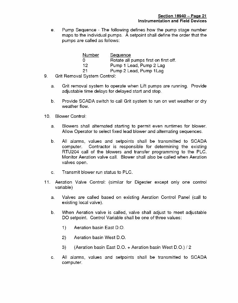
e. Pump Sequence - The following defines how the pump stage numbermaps to the individual pumps. A setpoint shall define the order that thepumps are called as follows:
Number Sequence0 Rotate all pumps first on first off.12 Pump 1 Lead, Pump 2 Lag21 Pump 2 Lead, Pump 1 Lag
9. Grit Removal System Control:
a. Grit removal system to operate when Lift pumps are running. Provideadjustable time delays for delayed start and stop.
b. Provide SCADA switch to call Grit system to run on wet weather or dry
weather flow.
10. Blower Control:
a. Blowers shall alternated starting to permit even runtimes for blower.Allow Operator to select fixed lead blower and alternating sequences.
b. All alarms, values and setpoints shall be transmitted to SCADAcomputer. Contractor is responsible for determining the existingRTU204 call of the blowers and transfer programming to the PLC.Monitor Aeration valve call. Blower shall also be called when Aerationvalves open.
c. Transmit blower run status to PLC.
11. Aeration Valve Control: (similar for Digester except only one controlvariable)
a. Valves are called based on existing Aeration Control Panel (call toexisting local valve).
b. When Aeration valve is called, valve shall adjust to meet adjustableDO setpoint. Control Variable shall be one of three values:
1) Aeration basin East D.O.
2) Aeration basin West D.O.
3) (Aeration basin East D.O. + Aeration basin West D.O.) / 2
c. All alarms, values and setpoints shall be transmitted to SCADAcomputer.
Section 16940- Page 22
Instrumentation and Field Devices
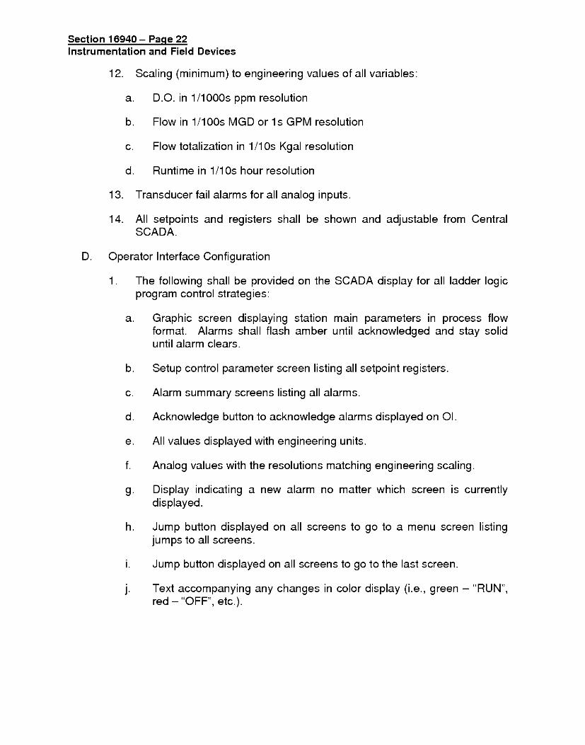
12. Scaling (minimum) to engineering values of all variables:
a. D.O. in 1/1000s ppm resolution
b. Flow in 1/100s MGD or ls GPM resolution
c. Flow totalization in 1/1Os Kgal resolution
d. Runtime in 1/10s hour resolution
13. Transducer fail alarms for all analog inputs.
14. All setpoints and registers shall be shown and adjustable from CentralSCADA.
D. Operator Interface Configuration
1 . The following shall be provided on the SCADA display for all ladder logicprogram control strategies:
a. Graphic screen displaying station main parameters in process flowformat. Alarms shall flash amber until acknowledged and stay soliduntil alarm clears.
b. Setup control parameter screen listing all setpoint registers.
c. Alarm summary screens listing all alarms.
d. Acknowledge button to acknowledge alarms displayed on 01.
e. All values displayed with engineering units.
f. Analog values with the resolutions matching engineering scaling.
g. Display indicating a new alarm no matter which screen is currentlydisplayed.
h. Jump button displayed on all screens to go to a menu screen listingjumps to all screens.
i. Jump button displayed on all screens to go to the last screen.
j. Text accompanying any changes in color display (i.e., green - "RUN",red - "OFF", etc.).

Section 16940 - Page 23
Instrumentation and Field Devices
k. Setup color convention to be used:
1 Background colors:a) Window - Grey.b) Changeable variable points - Pale Yellow.c) Non-Changeable variable points - Light Blue.d) Variable points shall be displayed in a box.
2) Control Switch Colorsa) Hand - Red.b) Off - Grey.c) Auto - Green.
3) Pump and Equipment Colorsa) Run - Green.b) Off - Red.c) Fail - Amber.d) Ready/Available - White.
4) Water Valve Colorsa) Closed - Redb) Modulating - Purple.c) Fully Open - Green.d) Undetermined - Grey.
5) Circuit Breaker Colorsa) Closed - Green.b) Open - Red.
6) Relay Logic Colorsa) Closed Relay Contact - Greenb) Open Relay Contact - Red.
SCADA graphics representing data and alarms shown on 01 screensprovided by package system suppliers (i.e. RO, etc.). All alarms anddata
2. SCADA screens shall be provided for all Contract Drawing P&IDs,including those where PLC programs are provided by others.
a. Contractor shall coordinate with other Suppliers to obtain PLC data tocomplete SCADA graphic configuration.
b. SCADA screens shall be provided that simulate the data displayed onOperator Interfaces provided by packaged systems. All run statuses,setpoints and alarms shall be displayed on the SCADA screens.
3. Configure SCADA Graphics on new SCADA computer.
a. SCADA database of tagnames that are used in the ContractDocuments control strategies shown on Contract Drawings andtransferred between processors.

Section 16940- Page 24Instrumentation and Field Devices
b. Graphic screens representing the plant process flow as shown onP&IDs. Graphic screen of the plant overview will also be updated.
c. Control folders listing process values and control setpoints.
d. Flow and runtime summary screens.
e. Historical Data Export of data.
f. Alarm annunciator screens similar to standard mechanical alarmannunciators.
g. PLC maintenance screens representing PLC racks and I/O input andoutput cards. Enable / Disable selection shall be made with twobuttons. "Enable" button shall be green when enabled and grey whendisabled. "Disable" button shall be red when disabled and grey whenenabled.
h. Realtime (1,4, 8 & 12 hour) and Historical Trends of process variables.
i. SCADAlarm autodialer callout on new alarms including alarmsgenerated by PLCs provided by others under this Contract (i.e. ROPLC, etc.). A process values menu will be developed by the SystemSupplier with the Operators' input so they may access key values andstatus.
SCADA database, Graphics screens, control folders, alarm
annunciator screens, PLC maintenance screens andRealtime/Historical trends shall be developed for PLCs provided byothers under this Contract. System Supplier is responsible forobtaining all required information from various Contractors to developSCADA graphics necessary for monitoring and controlling newequipment.
E. The Contractor shall include in his bid price an additional 200 hours of PLCprogram and SCADA Operator Interface graphic changes to be allocation to bedetermined during testing and start-up by the State representative. Any hourusage shall be made after written approval by State representative.Programming changes made during factory testing shall not be deducted fromthese hours unless agreed upon by State's Representative. Field programchanges shall be made by original programmer within five (5) working days afternotification in writing by State's Representative. All programming configurationchanges shall be performed by the original programmer and shall be made asdirected by the State's Representative in writing. A weekly report shall beprepared by System Supplier listing extra hour utilized, dates when work wasdone, description of work performed, and remaining number of extra hours.None of the hours shall be used for documentation, paperwork, travel,overhead, construction management, etc. that are not related to programming

Section 16940 - Page 25Instrumentation and Field Devices
changes since this is included in the hourly rate without written approval fromState's Representative. All hours not used shall be allocated for additional PLCprogram changes as directed by State representative during the one yearwarranty period.
PART 3 - EXECUTION
3.1 WORKMANSHIP
A. All instrumentation work in this Contract shall conform to the CEC andstandards.
B. The Contractor shall employ personnel who are skilled and experienced in theinstallation and connection of all elements, equipment, devices, instruments,accessories, and assemblies. All installation labor shall be performed byqualified personnel who have had experience on similar projects. Provide firstclass workmanship for all installations.
C. Ensure that all equipment and materials fit properly in their installations.
D. Perform any required work to correct improper installations at no additionalexpense to the State.
E. The State reserves the right to halt any work that is found to be substandard orbeing installed by unqualified personnel.
F. Rejected equipment or equipment without approved Submittals shall beimmediately removed from the delivery or job site by the Contractor.
G. All Manufacturers' instructions are to be followed. One copy of O&M andinstallation instructions shall be made available to the State when equipment isfirst being installed.
H. Before beginning SCADA software development for each process area, meetwith the State for a four-hour Design Definition Meeting at the State's facility.
1. Ensure that the Contractor Project Manager, System Supplier Engineer,System Supplier SCADA & PLC software programmer, Engineer & State'srepresentative are in attendance.

Section 16940- Page 26Instrumentation and Field Devices
2. Discuss SCADA & PLC format, programming and setup requirements toensure that parties involved have a clear understanding of the Contractrequirements. This discussion is to cover graphic screen layout, colorconventions, text display menu system, PLC ladder logic etc. SystemSupplier to demonstrate preliminary SCADA screen color and graphiclayout by bringing a configured PC loaded with SCADA graphics to themeeting. State shall have final determination during this meeting on thecolor conventions, alarm handling with color and display format.
3. System Supplier to demonstrate sample SCADA screen color and graphiclayout by bringing a configured PLC and PC loaded with modified SCADAgraphics to the meeting.
4. System Supplier to provide schedule for Preliminary Design Review andCritical Design Review.
5. Meeting shall occur 6 weeks prior to process area installation.
Meet with the State for a 4-hour SCADA & PLC Preliminary Design Reviewmeeting at the State's facility for each process area.
1. Ensure that the Contractor Project Manager, System Supplier Engineer,System Supplier SCADA & PLC software programmer, and Engineer &State's representative are in attendance.
2. Provide SCADA & PLC software preliminary design submittals for reviewand discussion 10 working days prior to meeting.
3. System Supplier to demonstrate revised SCADA screen color and graphiclayout by bringing a configured PLC and PC loaded with modified SCADAgraphics to the meeting.
4. System Supplier to demonstrate complete understanding of PLC controlsequence of operations and SCADA setup.
5. System Supplier to assign action items with required completion date.Contractor to submit report of completed action items to the State on orbefore designated date.
6. Meeting shall occur 4 weeks prior to process area installation.
J. Meet with the State for a 4-hour SCADA & PLC Critical Design Review meetingat the State's facility prior to start of any factory test for each process area.
1. Ensure that the Contractor Project Manager, System Supplier Engineer,System Supplier SCADA & PLC software programmer, and Engineer andState's representative are in attendance.

Section 16940 - Page 27Instrumentation and Field Devices
2. Provide preliminary SCADA & PLC Software Operations and MaintenanceManual.
3. System Supplier to demonstrate the complete SCADA & PLC setup. Allstation display and setpoint parameters will be checked for completenessby bringing PC and PLC both fully programmed & setup to the meeting.
4. System Supplier to demonstrate all SCADA screens for review andcomment.
5. System Supplier to assign action items with required completion date.Contractor to submit report of completed action items to the State on orbefore designated date.
6. Meeting shall occur two weeks prior to process area installation.
K. All equipment installed by the Contractor shall be in accordance with theDrawings and the manufacturer's recommendations & instructions and shalloperate to the State Representative's satisfaction. Follow all Manufacturers'instructions for handling, receiving, installation, and pre-check requirementsprior to energization. After energization, follow manufacturer's instructions forprogramming, set-up and calibration of equipment. The Contractor shall beresponsible for, and shall correct by repair or replacement, at his own expense,equipment which, in the opinion of the State Representative has been causedby faulty mechanical or electrical assembly by the Contractor. Necessary teststo demonstrate that the electrical and mechanical operation of the equipment issatisfactory and meets the requirements of these Specifications shall be madeby the Contractor at no additional cost to the State.
3.2 INSTALLATION
A. Install and supply all products necessary, at no additional cost to the State, toprovide an operational system. This shall include the following:
1. Contract Drawings are intended to show the basic functional requirementsof the instrumentation system and do not relieve the Contractor from theresponsibility to provide a complete and functioning system.
2. Provide relays, signal converters, isolators, boosters, power conditioners,circuit cards, and other miscellaneous devices as required for the properinterface.
3. Provide analog loop isolators where required to eliminate "ground loops."
4. All wires shall be identified with machine printed labels. Plastic wire guttersshall be used for routing of wire bundles. Wiring shall be neat and lacedwith plastic tie wraps.

Section 16940- Page 28Instrumentation and Field Devices
5. The instrumentation and accessory equipment shall be installed inaccordance with the manufacturer's instructions and located as shown onthe Drawings or as approved by the State Representative. Whenmanufacturer's installation literature specifies a particular location ororientation in a process line due to measurement accuracy considerations,the installation shall be in conformance with the manufacturer'sinstructions.
6. Engineering scales and charts for all instruments shall be provided thatmatch the range of instruments that monitor the process.
7. Power to instruments and instrument loops shall be from a single source ifpossible providing the highest integrity: e.g., from the loop primaryreceiving instrument/module, or from a UPS when so specified. A loopshall not be dependent on a diversity of multiple power sources, unlessotherwise indicated on the Contract Drawings.
B. Instrument Installation Methods:
1. Install instruments at the location shown on the Plans or approved by theState's Representative. Instruments shall be NEMA rated for the installedlocation.
2. Install instruments per manufacturer's instructions at all times. Provide acopy of manufacturer's installation requirements prior to startinginstallation.
3. Install level and plumb.
4. All instruments shall be provided with floor stands or wall brackets asshown or required.
5. Mounting hardware, stands, channels, and spacers shall be eithergalvanized steel, stainless steel, or non metallic to match the NEMA ratedlocation.
6. All screws and bolts shall be stainless steel.
7. Field instruments shall be mounted so that they can be readilyapproached and easily serviced, and so they do not restrict access tomechanical equipment. Field instruments not directly mounted shall bemounted on a pipe stand or local panel, unless otherwise indicated on theDrawings.
8. Field instrument enclosures shall be NEMA 4X minimum. For indoorcorrosive environments, or where otherwise specified, enclosures shall beNEMA 4X.

Section 16940 - Page 29Instrumentation and Field Devices
9. Connections from rigid conduit systems to field instruments shall be madewith jacketed flexible conduit with a maximum length of 3 feet.
10. Install water proof seals on all conduits to outdoor instruments.Installation shall be such that liquid shall not enter instrument or enclosureto which the conduit is connected.
11. All parameter set-up and programming shall be performed by theContractor at no additional cost to the State.
C. Wiring and Raceway Installation Methods:
1. Instrumentation wiring shall be carried in conduits. All analog circuits shallbe run as twisted pairs or triads. In no case shall a circuit be made upusing conductors from different pairs or triads. Triads shall be usedwherever three wire circuits are required. Triads are not to be formed byusing two pairs. Terminal blocks shall be provided at all instrument cablejunctions and all wires shall be identified at such junctions. Instrumentationwiring shall be run without splices between instruments, terminal boxes, orpanels.
2. The number of signal wires listed on the Drawings is approximate only,and the Contractor shall determine the required number of signal pairs ortriads to properly connect the system furnished, especially whensubstituting equipment.
3. When stipulated "manufacturer supplied cable" in the conduit schedule, itdirects the Contractor to have the manufacturer supply the cable for thelength of the conduit run.
4. All equipment and instrumentation located below grade shall have conduitdrain boxes and plug conduit interior to form an effective barrier to keepout water traveling down conduit into equipment and instrumentation whennecessary at no additional cost to the State.
D. Wiring, grounding, and shielding methods. It is important to observe goodgrounding and shielding practices in the generally noisy environment in thisapplication. The following practices shall be observed unless modified bymanufacturer's standards:
1. Each electronic equipment chassis shall be grounded to power ground.
2. All analog signals shall be transferred over shielded twisted pair cables.
3. All communication signals shall be transferred over shielded cables.

Section 16940- Page 30Instrumentation and Field Devices
4. All shields of analog inputs to the components shall be connected at thecomponents unit only. They shall not contact ground at any other pointincluding the transmitters.
5. All shields of analog outputs from the components shall be grounded onlyat the receiving device. They shall not contact ground at any other pointincluding the components.
6. Status and alarm signals routed through noisy environment shall betransferred over shielded twisted pair cables using 24VDC control andinterface relay for transition to 120VAC circuits.
7. Each shield, which is not connected to ground, shall be covered with aheat shrink insulating boot. Shields shall be connected together at eachtransition from one cable to another for a continuous effective shieldcircuit. All shields shall be connected on terminal blocks.
8. Isolating amplifiers shall be provided within the panel for field equipmentcreating a ground loop.
3.3 SUPPLIER SERVICES
A. The Contractor shall be responsible for each Supplier of equipment to providethe following minimum services for each type of instrument supplied.
1. The Supplier shall use a qualified instrumentation field technician (salesrepresentatives are not acceptable) to perform services listed herein.Technician shall be authorized or certified by instrument manufacturer toinstall and start-up instrument. Provide resume of technician and relatedexperience with related instrument prior to installation.
2. Advise and instruct Contractor on installation requirements.
3. Check, calibrate, and place equipment in operation.
4. All programmable devices shall be programmed and tested prior tostartup. Programming shall be adjusted or changed as directed by theState or State Representative, at no additional cost. A listing of allprogramming and setup parameters shall be placed in O&M manual atend of project.
5. Coordinate with the State's Representative and setup all alarm, process,and operation setpoints.
6. Perform the acceptance tests.
7. Visit the job as often as required and spend as much time as necessary toensure an operational instrumentation system.

Section 16940 - Page 31Instrumentation and Field Devices
8. Be readily available by telephone to answer all questions on suppliedequipment.
9. Provide training as specified below:
a. General:
1) Field training shall be administered on site using the deliveredsystem in real time situations. Field training shall not start untilthe "field" tests on the corresponding equipment have beencompleted and the corresponding operating instructions havebeen submitted and approved.
2) The "Training Plan" shall be conducted by a qualified supplierperson(s), who has conducted similar training for the type ofSystem supplied.
3) Acceptable Operation and Maintenance Manuals shall be onsite and available when training sessions are implemented.
b. Classroom Training (24 hours duration on site):
1) The level of classroom training shall be sufficient to familiarizethe State Representative personnel with the Plant Controls andoperation.
2) The level of classroom training shall be sufficient to familiarizethe personnel with the operation and maintenance of thesystem. All essential system operating procedures shall bedescribed as required to enable State Representative'spersonnel to observe the equipment operation. Preventivemaintenance procedures shall be described as required toenable personnel to maintain the equipment.
3) State personnel shall be trained in radio programming andcontrol strategies prepared for this project. The level of trainingshall enable the State personnel to understand the program,make programming changes to the system and to debug theprogram.
4) Utilize O&M manual and review in detail.
c. Field Training:
1) Field training shall be held on-site after classroom training forthe equipment has been completed.

Section 16940- Page 32Instrumentation and Field Devices
2) Supplier shall provide field training for a minimum of eight (8) ofthe State's engineering, operations and maintenance personnel
3) The "diagnostic and calibration" training, sixteen (16) hoursminimum, shall demonstrate radio hardware diagnosticroutines, test equipment, radio communication setup, and testprocedures as required to enable the personnel to detect andisolate system faults to the circuit board or module level and toimplement repairs by replacing failed circuit boards or modules.Demonstrate uploading and downloading software to make
backups and restore programs.
4) The "operator" hands-on training, twenty-four (24) hoursminimum, shall be given to show to non-technical and technicalState Representatives the basics in day-to-day operations andcontrol strategies involving the electrical and control systems.Preventive maintenance procedures shall also bedemonstrated for State Representative personnel during thistraining period.
d. Training on each type of field device shall provide a minimum of four(4) hour of on-site field training to instruct State personnel in the use,operation, calibration, programming, and maintenance on eachdifferent type of "field" instrument. This applies all field devices.
e. Responsibility to provide primary elements in a timely manner, forinsertion into the process line, coordinating size and material typewhen applicable, overseeing the actual installation, calibration, andacceptance testing.
3.4 ACCEPTANCE TESTS
A. Instrumentation tests shall be conducted per the following criteria:
1 . As a minimum, all the tests indicated/specified on the test formsInstrumentation Data Sheet and Calibration Record Test Form TF-1 andOperational Device Check & Test Form TF-2 in Appendix "A" shall beperformed by the Contractor as listed for the instrumentation and fielddevices in Appendixes "B" and "C".
2. Test equipment used for testing shall be of suitable quality so as not tomask performance deficiencies. All test equipment shall be traceable toNational Bureau of Standards and have been calibrated within six monthsof test date.
3. Testing shall be accomplished using simulated inputs only with priorwritten approval of the State.

Section 16940 - Page 33Instrumentation and Field Devices
4. The overall accuracy of each instrument loop shall be checked to ensurethat it is within acceptable tolerance.
5. Calibration stickers shall be supplied for all equipment and instruments.Calibration stickers shall list the following information:
a. Tag number.
b. Calibrated by whom (name), firm, city and telephone number.
c. Date calibrated.
d. Calibration range.
e. Comments.
6. The Contractor shall provide a minimum of two (2) hours of field testing foreach instrument. If any instrument has not been fully tested during itsallotted time, the Contractor shall provide additional hours for finishingtesting of the instrument, to be paid by the Contractor.
B. The completion of the above tests does not relieve the Contractor from
warranties specified elsewhere in this division.
3.5 TRAINING
A. Training on each type of field device shall provide a minimum of four (4) hour offield training to instruct State personnel in the use, operation, calibration,programming, and maintenance on each different type of "field" instrument.This applies all field devices.
3.6 SPARE PARTS
A. The Contractor shall make available any replacement parts that are notmanufacturer's normal stock items for immediate service and repair of all theinstrumentation equipment throughout the warranty period.
B. The following spare parts shall be provided to the State as part of this Contract:
1. Ten (10) fuses for each type of fuse.
2. Ten (10) lamps for each type of light.
C. Spare parts shall be packaged for safe shipping, storage, and clearly labeledwith part name and number and the corresponding equipment tagname.

Section 16940- Page 34
Instrumentation and Field Devices
3.7 FINAL ACCEPTANCE
A. Final acceptance will be given by the State after the equipment has passed the"final acceptance trial period", each deficiency has been corrected,
documentation has been provided, and all the requirements of designdocuments have been fulfilled.
B. At the end of the project, following the completion of the field tests, and prior tofinal acceptance, the Supplier shall provide the following to the State:
1. Each Operation and Maintenance Manual shall be modified orsupplemented by the Supplier to reflect all field changes and as-builtconditions.
2. A listing of all programming and setup parameters (including fieldinstruments) for insertion into the O&M manual.

Section 16940 - Page 35Instrumentation and Field Devices
APPENDIX "A"
TEST FORMS
Index of Forms:TF-1 Instrumentation Data Sheet and Calibration Record Test FormTF-2 Operational Device Checks and Tests Form

Section 16940- Page 36
Instrumentation and Field Devices
APPENDIX "B"
16940 INSTRUMENTATION AND FIELD DEVICES INDEX