section 16700 v5 - mccarran international airport 16700.pdf · d. ansi/tia/eia-606 - tia...
TRANSCRIPT

SECTION 16700
TELECOMMUNICATIONS INFRASTRUCTURE
Clark County, Department of Aviation Standard Specifications – 16700 Ver. 5.0 May 2015 Page 1 of 21
PART 1 GENERAL 1.1 SUMMARY
A. The telecommunications (telecom) infrastructure provides the basic infrastructure for the transport of voice and data signals throughout the facility. This is often regarded as just the telecommunications cable system that carries the information, but also properly includes the spaces (e.g., IDF rooms) that contain telecom equipment, the pathways (e.g., conduit, cable tray) that contain the telecom cable, any required telecom grounding/bonding and electrical power provisioning, cable terminations, mounting or installation hardware such as racks, wire ways, etc., and related administration of all components.
B. Telecommunications is included within the responsibility of the electrical design firm for this
project, specifications for typical electrical items will be found in the electrical specifications and on the electrical drawings. This includes specifications for conduit, cable tray, telecom grounding busbars, and telecom space panelboards. This Section for the telecommunications infrastructure covers the remaining items as listed in 1.2.
C. It is the intent of these Specifications to provide a complete workable telecommunications
infrastructure ready for OWNER's use. Any item not specifically shown on the drawings or called for in these Specifications, but normally required to conform to this intent, are to be considered as part of the Contract. CONTRACTOR shall provide a complete installation for the telecommunications structured cable plant including all cross connections and terminations in accordance with project requirements.
1.2 SECTION INCLUDES
A. Part 1 Preliminaries, scope, qualifications, bidding, etc. B. Part 2 Product requirements and specifications. C. Part 3 Installation requirements and specifications. D. Part 4 Administration (conventions, labeling, etc.) E. Part 5 Cabling systems acceptance testing.
1.3 RELATED SECTIONS
A. Section 16050 – Basic Electrical Requirements.
B. Section 16130 – Raceway and Boxes.
C. Section 16133 – Cable Trays.
D. Section 07270 – Firestopping. 1.4 REFERENCES Many of the ANSI/TIA/EIA standards are in the process of revision with updates expected during the design phase of this project, or shortly thereafter. The latest publications of these documents are required for this project even though the listing below may indicate an earlier version. This especially applies to the

SECTION 16700
TELECOMMUNICATIONS INFRASTRUCTURE
Clark County, Department of Aviation Standard Specifications – 16700 Ver. 5.0 May 2015 Page 2 of 21
ANSI/TIA/EIA-569-A, and -607, standards. A. ANSI/NFPA 70 - National Fire Protection Association standard for electrical code, i.e., the
National Electrical Code (NEC). B. ANSI/TIA/EIA-568-B Set - TIA commercial building cabling standard - defines a generic
cabling system for a multiproduct, multivendor environment. C. ANSI/TIA/EIA-569-A - TIA commercial building standard for telecommunications pathways
and spaces - defines the minimum requirements for both pathways for telecommunications cabling and spaces for telecommunications equipment.
D. ANSI/TIA/EIA-606 - TIA administrative standard for the telecommunications infrastructure of
commercial buildings. E. ANSI/TIA/EIA-607 - TIA grounding and bonding standard for commercial buildings. F. ANSI/TIA/EIA-758 - TIA customer-owned outside plant standard. G. BICSI TDMM Current Ed. – BICSI’s (Building Industry Consulting Service International)
Telecommunications Distribution Methods Manual (TDMM). H. FCC Part 15 - Federal Communication Commission document relating to allowable radiated
emissions. I. ISO 9000 - Manufacturing quality control standard (certification). J. UL 1459 – Underwriter’s Laboratories fire resistance requirements.
1.5 SUBMITTALS
A. Submit under provisions of Division 1 – General Requirements. B. Provide manufacturer’s catalog information showing dimensions, colors, and configurations of
all materials and equipment furnished under this section. C. Submit plan view layout, drawn to scale (¼” to 1’ or ½” to 1’), for all telecommunications
spaces in both electronic format (CADD Drawings). In addition, provide front elevation of racks with pertinent heights and termination hardware identified.
D. Submit termination and cross connect schedule for OWNER review and approval prior to
proceeding with termination/punch down within the telecommunications spaces. E Manufacturer’s instructions:
1. Indicate application conditions and limitations of use stipulated by product testing agency specified under regulatory requirements.
2. Include instructions for storage, handling, protection, examination, preparation, operation and installation of product. a. A technical data sheet from the manufacturer shall be included with the
response for each product proposed. This data sheet shall include the physical specifications as well any relevant electrical and transmission characteristics.
SECTION 16700
TELECOMMUNICATIONS INFRASTRUCTURE
Clark County, Department of Aviation Standard Specifications – 16700 Ver. 5.0 May 2015 Page 3 of 21
F Pre-Qualification Certificate
Submit documentation from the manufacturer indicating completion of pre-qualification requirements. 1. Training certificates for installation of the proposed products shall be submitted with
the manufacturer’s documentation.
G Factory Test 1. Vendor shall submit all relevant factory test information prior to installation. If
equivalent product(s) are substituted, the equivalent product(s) must show demonstrated and documented equivalence to the product(s) specified.
H. Warranty
1. Submit relevant warranty data indicating warranty compliance. 1.6 SCOPE OF WORK The work required for this project includes:
A. The acquisition, inspection, and storage of all products required for this work as detailed in Part 2 of this specification. This includes labor associated with these product-associated tasks.
B. The installations required in Part 3 of this document and illustrated on the Drawings, including
all associated labor to perform and complete these installations. C. All administration tasks described in Part 4 of this document. D. All acceptance testing work as detailed in Part 5 of this document. E. Related work, associated with the work described in A-D above includes:
1. All services, facilities, tools and equipment necessary or used to perform, complete, and test the installations.
2. Provide firestopping of all conduits, cable trays, rated wall and floor penetrations, etc. related to these Specifications.
3. The furnishing and installation of non-specified miscellaneous hardware and consumable items (e.g., nuts, bolts, washers, cable ties, cable preparation materials, pulling compounds, etc.).
4. Preparation and submission of unit pricing sheets, product data sheets, shop drawings, and record drawings.
5. The furnishing and installation of TR (IDF) ladder rack(s) and other wire management hardware such as D-rings, Velcro wraps, etc.
1.7 CONTRACTOR QUALIFICATIONS
A. ABF Cable Installer: The proposing company shall be manufacturer certified in designing and installing the air-blown fiber system selected for this project. The company shall have a minimum of three (3) years experience and have completed at least three (3) previous installations of similar or greater size than this project.
B. Horizontal Cable Installer: The proposing company shall be manufacturer certified in
SECTION 16700
TELECOMMUNICATIONS INFRASTRUCTURE
Clark County, Department of Aviation Standard Specifications – 16700 Ver. 5.0 May 2015 Page 4 of 21
designing and installing the SYSTIMAX structured cabling system for this project. The company shall have a minimum of three years experience and have completed at least three previous installations of similar or greater size than this project.
C. Management: Project management and supervisory personnel shall be experienced in
overseeing the installation of telecommunications cabling systems of the types and sizes to be provided as part of this work. The CONTRACTOR’S on-site management and supervisory staff shall include a BICSI, Registered Communications Distribution Designer (RCDD).
1.8 CODE, REGULATORY, STANDARDS, PRACTICE
A. Generally, the telecommunications pathways, spaces, grounding/bonding, cabling and administration shall conform to the requirements of the references listed in 1.3. Occasional exceptions to these documents may be required due to local code variations or unique requirements of the project. CONTRACTOR shall identify exceptions and notify OWNER in writing prior to proceeding with the associated work.
B. Generally, installation methodology and practice shall conform to the BICSI TDMM.
Occasional exceptions to the TDMM may exist due to local code variations or unique requirements of the project. CONTRACTOR shall identify exceptions and notify OWNER in writing prior to proceeding with the associated work.
1.9 STAFFING, TOOLING/EQUIPMENT
A. General 1. Provide sufficient supervisory personnel throughout the project to efficiently manage
the installation and testing work. 2. Provide staffing throughout the project as necessary to meet the construction
schedule.
B. Supervisory staff 1. Qualified supervisory staff shall be in charge of the work at all times. Supervision
shall be present, in the field, on a daily basis during the performance of the work.
C. Tooling/equipment 1. Provide and use the proper tools and test equipment in the performance of each
activity. Tools must be in good working order and test equipment must be properly calibrated.
2. Provide sufficient skilled labor and quantities of each type of test set or test tool to complete testing within the agreed upon test period. All test sets or tools of a given type shall be from the same manufacturer.
PART 2 PRODUCT REQUIREMENTS AND SPECIFICATIONS 2.1 GENERAL
A. All products furnished shall be new, unused, free of defects, undamaged, and free of corrosion.
SECTION 16700
TELECOMMUNICATIONS INFRASTRUCTURE
Clark County, Department of Aviation Standard Specifications – 16700 Ver. 5.0 May 2015 Page 5 of 21
B. All products shall meet all applicable codes and standards. C. All applicable products shall be listed and classified by Underwriter’s Laboratories, Inc. as
suitable for the purpose specified and shown. D. Any given product shall be the product of one manufacturer throughout the facility. Unless
specifically noted otherwise or approved by OWNER, multiple manufacturers of any one item is not permitted.
E. All copper and optical fiber cable shall carry a manufacturer’s warranty of fifteen years. F. Any product bid and installed per this Section shall be from a company having a minimum of
three (3) years experience specializing in the manufacturing of that product technology. G. Delivery, storage, and handling of products:
1. Upon delivery to the project site, all products shall be visually inspected for damage. Damaged goods shall be returned to the supplier and replaced at no additional cost to OWNER.
2. Wire and cable stored at the construction site shall be stored in a clean, dry, covered location, which has been approved by OWNER. Maintenance and security of materials storage space is the responsibility of CONTRACTOR.
3. Prior to installation, each end of each continuous length of cable shall be kept sealed by suitable means to protect against the entrance of moisture. Each continuous length of cable shall be placed on an individual reel.
H. If post-manufacture performance data has been supplied with the product, copies of such
data shall be provided to OWNER upon request.
2.2 AIR-BLOWN OPTICAL FIBER CABLE BACKBONE
A. General: The Air Blown Fiber (ABF) system installed under this project shall be Sumitomo Electric Lightwave Corp. and denoted as their FutureFlex® Air Blown Fiber System. The new system will match the existing system, which has the following characteristics: 1. Utilize nitrogen to install multi-strand optical fiber bundles through a tubing system.
The tubing system allows for the addition of fibers or the change of the type of fiber without pulling additional innerduct or optical fiber over existing fibers.
2. Allows individual tubes to be routed as required through the use of simple push-fit connectors.
3. The optical fiber has the capability of being removed and re-used without damage to the cable.
4. Each fiber is buffered with color-coded PVC. 5. Existing fiber part numbers are Multimode fiber: Furon FB-18M6, Singlemode fiber:
FB-18SX.
B. Tube cable and Tube Distribution Units (TDU). 1. Tubing and the ABF distribution boxes supplied for this work shall be compatible with
existing tubing and boxes.
SECTION 16700
TELECOMMUNICATIONS INFRASTRUCTURE
Clark County, Department of Aviation Standard Specifications – 16700 Ver. 5.0 May 2015 Page 6 of 21
2. The tubing material shall conform to all required fire safety codes for the areas within which it will be installed.
3. Tube Distribution Units shall be appropriately sized for the amount of tubing to be used but in no case smaller than “24x20x7” and shall meet with OWNER’s approval.
C. Fiber specifications:
1. Multimode 62.5/125 µm diameter tight-buffered optical fiber, with fiber counts as indicated on drawings, with mechanical and transmission performance specifications that meet or exceed ANSI/TIA/EIA-568-B.3 Note: Listed type OFNP, OFNR, OFCR, and/or OFCP (as required in the NEC).
2. Singlemode inside plant optical fiber, with fiber counts as indicated on drawings, with mechanical and transmission performance specifications that meet or exceed ANSI/TIA/EIA-568-B.3 Note: Listed type OFNP, OFNR, OFCR, and/or OFCP (as required in the NEC).
D. Configuration: Refer to drawing for tubing configuration.
2.3 OPTICAL FIBER CONNECTORS
A. Description: Zero pig tail splice-on (singlemode, multimode) optical fiber connectors B. Specifications:
1. Ceramic ferrule. 2. Connectors shall meet or exceed the minimum mechanical and optical
characteristics for optical fiber connectors as specified in ANSI/TIA/EIA-568-A. 3. Shall prevent momentary disconnect when an axial load is placed on the cable.
C. Configuration: SC connectors shall be provided.
D. Acceptable manufacturers: 1. Sumitomo 2. Owner Approved Equivalent
2.4 OPTICAL FIBER TERMINATION PANELS
A. Description: 19-inch, 1U rack-mounted optical fiber patch panel, accommodating 48 fiber terminations is the standard at McCarran International Airport.
B. Specifications:
1. 48-terminations use Systimax Solutions (CommScope), 360G2 series patch panels. C. Configuration: Complete with termination inserts and connectors, cable manager (wire
minders) placed inside each patch panel, and connectors provided for all 48 termination positions.
D. Acceptable manufacturer:
1. Systimax Solutions (CommScope) 2. Owner Approved Equivalent
SECTION 16700
TELECOMMUNICATIONS INFRASTRUCTURE
Clark County, Department of Aviation Standard Specifications – 16700 Ver. 5.0 May 2015 Page 7 of 21
2.5 OPTICAL FIBER PATCH CORDS
NOTE: OWNER will install and connect equipment in racks. A. Description: Optical fiber patch cords for use with patch panels. B. Specifications:
1. Fiber strand: Multimode 62.5/125 µm and Single Mode. 2. Patch cord outside diameter: 3.0mm 3. Connectors same specifications as listed in 2.3 B. 4. Cords shall meet or exceed the minimum mechanical and optical characteristics for
optical fiber patch cords as specified in ANSI/TIA/EIA-568-B.3.
C. Configuration: 2-strand, Duplex construction.
D. Acceptable manufacturers: 1. Systimax Solutions (CommScope) 2. Owner Approved Equivalent
2.6 COPPER TERMINATION PANELS - VOICE APPLICATIONS
Note: Separate UTP termination panels shall be used for voice and data applications.
A. Description: 19-inch rack-mountable 8-pin modular connector patch panel used for UTP voice applications.
B. Specifications:
1. Connecting hardware shall meet or exceed the minimum mechanical and electrical characteristics for Category-6.
2. Modular connectors shall be backward compatible with Cat 5/5e components. C. Configuration: Capable of housing (48) 8-pin modular connector terminations in a 48 port
arrangement. Note: The TIA T568B wiring configuration will be used for modular connectors. D. Acceptable manufacturers:
1. Systimax Solutions (CommScope) 2. Owner Approved Equivalent
2.7 COPPER TERMINATION PANELS - DATA APPLICATIONS
Note: Separate UTP termination panels shall be used for voice and data applications.
A. Description: 19-inch rack-mountable 8-pin modular connector patch panel used for UTP data applications.
B. Specifications:
1. Connecting hardware shall meet or exceed the minimum mechanical and electrical characteristics for Category-6 modular connectors as specified by TIA.
2. Connectors shall be backward compatible with Cat 5/5e components.

SECTION 16700
TELECOMMUNICATIONS INFRASTRUCTURE
Clark County, Department of Aviation Standard Specifications – 16700 Ver. 5.0 May 2015 Page 8 of 21
3. TIA T568B wiring configuration. C. Configuration: 48-position patch panel.
D. Acceptable manufacturers:
1. Systimax Solutions (CommScope) 2. Owner Approved Equivalent
E. Modular connector selection: As part of the modular connector selection process, connector manufacturer/vendors shall submit, in writing, their minimum guaranteed specifications for attenuation and NEXT.
2.8 TERMINATION RACKS FOR FIBER, VOICE, AND DATA PANELS
A. Description: Termination racks for the mounting of fiber, voice, and data panels and their associated cabling and connecting hardware, similar to existing racks installed at McCarran Intl. Airport.
B. Specifications:
1. Standard EIA 19-inch, High-strength, lightweight aluminum, 84 inches high, minimum usable height of 77 inches.
2. Racks shall meet the requirements of EIA-310-D and shall be UL listed. 3. Racks shall incorporate subtle light-blue RMU markings on both uprights (front and
back). Numbers shall start from the bottom. 4. Racks for patch panels shall have full-height 6-inch vertical slotted cable ducts (with
covers) installed on the front side of the rack and open on the back. These ducts will allow cables plugged into the panels to be routed horizontally to either the left or right duct on each side, through the slots, and then loosely either up or down the duct as required.
5. Racks for patch panels shall have horizontal wire management (nominal 4 inches square) with solid cover. Horizontal wire management shall be provided between all 48-port patch panels.
6. Provide 6’-0” plug strip on back frame of rack with 20-outlets that will be connected to a standard 20-amp service.
7. Provide 100-rack screws (black) per installed rack. C. Configuration:
1. Per OWNER’s instructions.. D. Acceptable manufacturers:
1. CPI Chatsworth Products 2. Owner Approved Equivalent
E. Acceptable Cable Management manufacturer:
1. CPI Chatsworth 2. Owner Approved Equivalent
2.9 EQUIPMENT CABINETS
SECTION 16700
TELECOMMUNICATIONS INFRASTRUCTURE
Clark County, Department of Aviation Standard Specifications – 16700 Ver. 5.0 May 2015 Page 9 of 21
A. Description: Cabinets for the mounting of electronic equipment within the IDFs. B. Specifications: 42-rack units, Dimensions (HxDxW) 78.4 x 42.13 x 23.62 inches. C. Configuration: Per OWNER’s instructions. D. Provide a vertical plug strip on back frame of rack, 3-circuits with a load capacity of no less
than 5700 VA with local metering and remote management capabilities via SNMP. E. Acceptable manufacturers:
1. American Power Conversion (APC) 2. Owner Approved Equivalent
2.10 COPPER UTP JUMPERS, PATCH CORDS, MOUNTING CORDS NOTE: OWNER will install and connect equipment in the racks. Contractor shall include one (1) 7-foot, Category-6 patch cord for 50% of the number of IMO ports in this bid. CONTRACTOR shall provide a unit price for additional patch cords in base bid. Per unit price shall be clearly identified separate from the remainder of the bid.
A. Description: Wire and cable used for circuit configuration.
B. Specifications:
1. All cross-connect or jumper wire shall be made of stranded cable. 2. All cross connect single pair jumper wire shall be red-black. 3. All patch cords shall be factory assembled and constructed with Category-6 cable
and connectors. C. Configuration: (Consult OWNER for allowable variations to following cable colors)
1. Patch cords used for data will be blue 2. Patch cords used for voice will be orange 3. Patch cords used for uplinks will be yellow
D. Acceptable manufacturers:
1. Systimax Solutions (CommScope) 2. Owner Approved Equivalent
2.11 COPPER UTP CABLE - HORIZONTAL (IDF TO USER OUTLET CABLE)
A. Description: High performance horizontal 4-pair Category-6 unshielded twisted pair (UTP), solid conductor cable.
B Specifications: Cable shall meet or exceed the minimum mechanical and electrical
characteristics for Cat 6 horizontal cable as specified by TIA. C. Configuration: (Consult OWNER for allowable variations to following cable colors.)
1. All voice cables shall be gray in color.
SECTION 16700
TELECOMMUNICATIONS INFRASTRUCTURE
Clark County, Department of Aviation Standard Specifications – 16700 Ver. 5.0 May 2015 Page 10 of 21
2. All data cables shall be light blue in color.
D. Acceptable manufacturers: 1. Systimax Solutions (CommScope) 2. Owner Approved Equivalent
E. Cable selection: As part of the cable selection process, cable manufacturers/vendors shall
submit, in writing, their minimum guaranteed specifications for cable attenuation, NEXT, and structural return loss.
2.12 INFORMATION MANAGEMENT OUTLETS (IMOs)
A. Description: An IMO is defined as a 4-position outlet box containing two 8-pin modular jacks for data applications and two 8-pin modular jacks for voice applications, using color coding to differentiate between the two applications. An IMO will either be wall-mounted or floor mounted and shall be a minimum size of 4-11/16” square. Consult with OWNER as to any allowable variations to IMOs.
B. Specifications:
1. All 4 jacks in an IMO shall meet or exceed the mechanical and electrical characteristics for Category-6 jacks as specified by TIA.
2. All floor outlets shall comply with ANSI/TIA/EIA-509-A-4 and have a brass carpet flange 3. Provide and install plastic dust covers for all jacks in floor mounted IMO’s.
C. Configuration: 1. The top two 8-pin modular connectors shall be orange in color, used for data
applications. 2. The bottom two 8-pin modular connectors shall be ivory in color, used for voice
applications. 3. Consult with OWNER to coordinate the outlet colors with the existing color scheme
at McCarran Intl. Airport to maintain consistency. Note: The TIA T568B wiring configuration will be used for all modular jacks.
D. Acceptable outlet manufacturers:
1. Systimax Solutions (CommScope) 2. Owner Approved Equivalent
E. Modular connector selections: As part of the modular connector selection process, connector
manufacturer/vendors shall submit in writing, their minimum guaranteed specifications for attenuation and NEXT.
F. Acceptable floor outlets manufacturers:
1. Systimax Solutions (CommScope) 2. Owner Approved Equivalent
SECTION 16700
TELECOMMUNICATIONS INFRASTRUCTURE
Clark County, Department of Aviation Standard Specifications – 16700 Ver. 5.0 May 2015 Page 11 of 21
G. Provide four (4) 4 pair Category-6 cables per IMO in accordance with 2.11 unless noted otherwise.
2.13 DATA OUTLETS
A. Description: A Data Outlet is defined as a 2-position outlet box containing two jacks. A Data Outlet will either be wall-mounted or floor mounted. Consult with OWNER as to any allowable variations to Data Outlets.
B. Specifications: 1. Both jacks in a Data Outlet shall meet or exceed the mechanical and electrical
characteristics for Category-6 jacks as specified by TIA. 2. All floor outlets shall comply with ANSI/TIA/EIA-509-A-4 and have a brass carpet flange. 3. Provide and install plastic dust covers for all floor mounted data outlets.
C. Configuration: Data Outlets shall be orange in color. Consult with OWNER to coordinate the
outlet color with the existing Data Outlet color to maintain consistency. Note: The TIA T568B wiring configuration will be used for both Data Outlet jacks.
D. Acceptable outlet manufacturers:
1. Systimax Solutions (CommScope) 2. Owner Approved Equivalent
E. Modular connector selections: As part of the modular connector selection process, connector manufacturer/vendors shall submit in writing, their minimum guaranteed specifications for attenuation and NEXT.
F. Acceptable floor outlet manufacturers:
1. Walker Systems 2. Systimax Solutions (CommScope) 3. Panduit 4. Owner Approved Equivalent
G. Provide two (2) 4 pair Category-6 cables per data outlet in accordance with 2.11 unless noted otherwise.
2.14 VOICE OUTLETS
A. Description: A Voice Outlet is defined as a 2-position outlet box containing two jacks. A Voice Outlet will either be wall-mounted or floor mounted. Consult with OWNER as to any allowable variations to Voice Outlets from those currently installed.
B. Specifications:
1. Both jacks in a Voice Outlet shall meet or exceed the mechanical and electrical characteristics for Category-6 jacks as specified by TIA.
SECTION 16700
TELECOMMUNICATIONS INFRASTRUCTURE
Clark County, Department of Aviation Standard Specifications – 16700 Ver. 5.0 May 2015 Page 12 of 21
2. All floor outlets shall comply with ANSI/TIA/EIA-509-A-4 and have a brass carpet flange.
3. Provide and install plastic dust covers for all floor mounted voice outlets.
C. Configuration: Voice Outlets shall be ivory in color. Consult with OWNER to coordinate the outlet color with the existing Voice Outlet color to maintain consistency.
Note: The TIA T568B wiring configuration will be used for both Voice Outlet jacks. D. Acceptable outlet manufacturers:
1. Systimax Solutions (CommScope) 2. Owner Approved Equivalent
E. Modular connector selections: As part of the modular connector selection process, connector
manufacturer/vendors shall submit in writing, their minimum guaranteed specifications for attenuation and NEXT.
F. Acceptable floor outlet manufacturers:
1. Systimax Solutions (CommScope) 2. Walker Systems 3. Owner Approved Equivalent
G. Provide two (2) 4 pair Category-6 cables per voice outlet in accordance with 2.11 unless
noted otherwise.
2.15 PLYWOOD BACKBOARD
A. Description: Wall-mounted plywood used for the mounting of termination blocks and equipment in the IDF and MDF.
B. Specifications: A-C interior grade or better, void-free plywood, 2.4m (8-ft.) high with a
minimum thickness of 19 mm (3/4 trade size). C. Configuration: All walls shall be lined. The plywood shall be installed with the “C” surface
facing the wall. The plywood shall be treated on all sides with at least two (2) coats of flat white, fire-resistant paint. Securely fasten the plywood to wall-framing members.
2.16 FIRESTOPS NOTE: All firestop products shall be listed and meet with the approval of the local authority having jurisdiction for each application situation. All penetration made to install building elements (e.g. conduits, cable trays, cables, fixtures, boxes) must be firestopped to return the barrier to its intended fire rating.
SECTION 16700
TELECOMMUNICATIONS INFRASTRUCTURE
Clark County, Department of Aviation Standard Specifications – 16700 Ver. 5.0 May 2015 Page 13 of 21
A. Description: The function of a firestop is to prevent fiber, smoke or water from passing through a barrier penetration.
B. Specifications: Used as deemed suitable mechanical or non-mechanical firestops: ready
sleeves, EZ path modules, putty, intrumescent sheets and wrap strips, silicone foams and pre-manufactured pillows.
C. Configuration: All firestop products shall meet with OWNER’s approval for ease of use in on
going cable operations. D. Acceptable manufacturers:
a. STI Firestop b. Abesco c. Owner Approved Equivalent
2.17 EQUIVALENT PRODUCT
A. Where manufacturers (and model numbers) are mentioned herein, it is to establish product description, arrangement, style, level of quality and cost. Equivalent products of other manufactures may be acceptable provided they are formally submitted and approved in accordance with the General Requirements for the project.
PART 3 INSTALLATION 3.1 GENERAL
A. See Part 4 for installation requirements related to the labeling of cables, panels, racks, faceplates, etc.
B. Data panel racks duct installation: Provide 4 inch square slotted wiring ducts, securely
mounted (e.g. bolted with lock washers) to the vertical rails of rack such that normal, frequent removed and replacement of the covers does not loosen the mounting over time.
C. All products shall be installed per applicable code requirements, manufacturer’s guidelines,
manufacturer’s requirements, manufacturer’s instructions, manufacturer’s procedures and applicable BICSI/TIA installation guidelines and methodologies. All products shall be installed in accordance with their listing.
D. Conduit and cable tray fill rules of ANSI/NFPA 70, local ordinance requirements, and TIA
shall be adhered to. E. Bending radius and pulling forces for ABF tube and copper cable:
1. CONTRACTOR shall observe the minimum bending radius and maximum pulling force restrictions as found in manufacturer‘s data and TIA specifications.
2. CONTRACTOR shall monitor pull tension continuously during installation.

SECTION 16700
TELECOMMUNICATIONS INFRASTRUCTURE
Clark County, Department of Aviation Standard Specifications – 16700 Ver. 5.0 May 2015 Page 14 of 21
3. A lubricant specifically manufactured for pulling lubrication and compatible with sheathing material may be used to meet pull tension requirements. CONTRACTOR shall utilize pulling lubricants that are approved by the manufacturer for the particular media involved. Petroleum grease shall not be used.
F. Cables and ABF tubing shall be protected from foot traffic, heavy carts, motorized traffic or
heavy/sharp loads placed upon them during installation. G. Any cable deemed by OWNER to have been damaged by improper installation, foot traffic,
etc. shall be replaced at no additional cost to OWNER. H. Cable slack and service loops shall be provided per BICSI guidelines.
I. The installed copper cabling system shall conform to FCC Part 15 radiation requirements. J. All fire stopping requirements of ANSI/NFPA 70 and any local authority requirements shall be
met. This also applies to floor mounted devices. K. Cabling shall be installed in a pre-approved route, as determined by OWNER. L. Each run of ABF tube bundle or UTP cable shall be installed using a single sheath with no
joints or splices.
3.2 FIBER INSTALLATION
A. Coordinate with OWNER regarding fiber installation in the tubing system. In general, fiber will be installed in a similar fashion to existing fiber plant.
B. Fiber installation: As indicated on drawings. C. Fiber termination:
1. All fibers shall be terminated in the IDFs onto the rack-mounted fiber panels, the number of panels in each IDF being specified. Racks shall be equipped with sufficient couplers and jumper storage shelves to terminate and secure 72 fibers.
2. Fan out all optical fiber cable to allow direct installation of connectors. Sleeve over individual fiber with a Kevlar reinforced furcation tube. At the convergence point of all furcation tubes, provide strain relief with a high-density plastic fan-out collar. Additionally, provide a minimum of 1-meter of slack fiber cable, coiled at each wiring connection/patch panel.
4. All fibers shall terminate into SC connectors. 5. Fibers shall be color-coded corresponding to the existing fiber installation scheme.
3.3 HORIZONTAL COPPER CABLING INSTALLATION
SECTION 16700
TELECOMMUNICATIONS INFRASTRUCTURE
Clark County, Department of Aviation Standard Specifications – 16700 Ver. 5.0 May 2015 Page 15 of 21
A. Coordinate with OWNER regarding horizontal cable routing and placement. In general, horizontal distribution will be installed in a similar fashion (except for cable bundling) to existing horizontal cabling.
B. Horizontal cable installation:
1. Install horizontal cable as indicated on the electrical drawings. Each horizontal cable shall be installed as a continuous run of cable, with no joints or splices, from the serving IDF room to the end user IMO or Data Outlet (i.e., star cabled from the IDF). Coordinate with OWNER regarding any questions as to termination locations.
2. The maximum horizontal cable distance between the IDF room rack and the work area outlet shall be 250-ft.
3. Special attention shall be given to cable as it is pulled off reels and installed in conduit or tray. Cable shall not be kinked, pulled over sharp corners, compressed or exposed to any activity that results in cable deformation.
C. Horizontal cable termination:
1. Maintain each individual cable sheath up to the point of termination by removing only as much cable sheath as is necessary and practical for cable termination.
2. Each pair shall not be untwisted anymore than necessary, preferably less than the maximum of one-half inch permitted by the TIA standard. The two conductors of each pair in the (4 pair) cable shall be in contact with one another up to the point the untwist begins for termination into the connecting hardware. From that point, the TIA maximum allowance for pair untwist shall not exceed to the point of termination on the connecting hardware.
3. All IMO and Data Outlet modular receptacle terminations shall be of the T568B configuration.
D. Cable dressing:
1. When securing and dressing the cabling, the method used shall be with the approval of OWNER and shall not cause any deformation of the cable sheath.
2. At the IDF room end of horizontal cabling, bundle all cables with Velcro from conduit or tray exit, through rack cable management continuing to the point of termination. Do not bundle cables within conduits. Provide a minimum of 3-meter service loop at the IDF room end and store on the cable ladder. Do not store service loops in vertical wire management.
3. Use Panduit vertical and horizontal cable management in racks. E. Casework cabling: Where horizontal cabling terminates inside casework which is provided by
others (e.g., gate counters, FIDS structures), CONTRACTOR shall route the cable within the pathways provided within the casework. Where applicable, CONTRACTOR shall terminate cables to outlets within the casework. If the casework does not include outlets, CONTRACTOR shall provide and install outlets within the structure. See drawings for clarification regarding outlets provided by others. Coordinate casework installation as required.
3.4 FIRESTOPPING
SECTION 16700
TELECOMMUNICATIONS INFRASTRUCTURE
Clark County, Department of Aviation Standard Specifications – 16700 Ver. 5.0 May 2015 Page 16 of 21
A. Upon completion of the installation, all cable pathways must be properly fire stopped per the NEC, local code requirements, and in full conformance with the manufacturers published installation instructions. The final field installation shall be reviewed and approved by the local AHJ.
PART 4 ADMINISTRATION Type, format, wording, printing, and placement of labels shall be coordinated with OWNER’s existing administration plan. Items and/or issues not addressed in OWNER’s established administration plan shall be addressed in accordance with TIA/EIA 606 Standard (e.g. cable tray, conduits, junction boxes, grounding systems, etc). All labels must be mechanically printed and not hand written. 4.1 COLOR CODING CONVENTIONS The following color-coding conventions shall be used:
A. Cable: 1. Voice cables, IDF to IMO, shall be gray. 2. Data cables, IDF to IMO, shall be light blue. 3. IDF to Data Outlet cables shall be light blue.
B. 8-pin modular jacks:
1. Data jacks in all IMOs shall be orange. 2. Voice jacks in all IMOs shall be ivory. 3. Jacks in all Data Outlets shall be orange.
C. Jumpers, cross-connect pair, patch cords:
1. All cross-connect single pair jumper wire shall be red-black. 2. Patch cords used for data shall be blue. 3. Patch cords used for voice shall be orange. 4. Patch cords used for uplinks shall be yellow.
4.2 HORIZONTAL CABLE LABELING CONVENTIONS
A. All cables shall be labeled at each end of the sheath indicating the Telecommunications room and patch panel port to which the cable is terminated. Permanently secure the label within 8 inches from both ends of the cable and at all pull boxes.
B. Labeling of all horizontal cable shall be consistent with the existing labeling scheme,
CONSULT WITH OWNER.
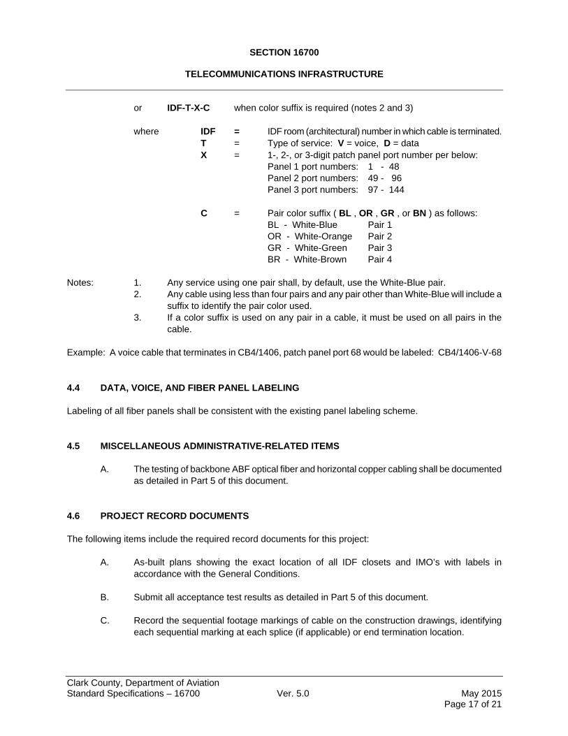
4.3 IMO AND DATA OUTLET FACEPLATE LABELING Labeling of all IMO and Data Outlet faceplates shall be consistent with the existing labeling scheme. The format for IMO and Data Outlet labeling is as follows: IDF-T-X when no suffix is required (typical IMO cable)
SECTION 16700
TELECOMMUNICATIONS INFRASTRUCTURE
Clark County, Department of Aviation Standard Specifications – 16700 Ver. 5.0 May 2015 Page 17 of 21
or IDF-T-X-C when color suffix is required (notes 2 and 3) where IDF = IDF room (architectural) number in which cable is terminated. T = Type of service: V = voice, D = data X = 1-, 2-, or 3-digit patch panel port number per below:
Panel 1 port numbers: 1 - 48 Panel 2 port numbers: 49 - 96 Panel 3 port numbers: 97 - 144
C = Pair color suffix ( BL , OR , GR , or BN ) as follows:
BL - White-Blue Pair 1 OR - White-Orange Pair 2
GR - White-Green Pair 3 BR - White-Brown Pair 4
Notes: 1. Any service using one pair shall, by default, use the White-Blue pair.
2. Any cable using less than four pairs and any pair other than White-Blue will include a suffix to identify the pair color used.
3. If a color suffix is used on any pair in a cable, it must be used on all pairs in the cable.
Example: A voice cable that terminates in CB4/1406, patch panel port 68 would be labeled: CB4/1406-V-68 4.4 DATA, VOICE, AND FIBER PANEL LABELING Labeling of all fiber panels shall be consistent with the existing panel labeling scheme. 4.5 MISCELLANEOUS ADMINISTRATIVE-RELATED ITEMS
A. The testing of backbone ABF optical fiber and horizontal copper cabling shall be documented as detailed in Part 5 of this document.
4.6 PROJECT RECORD DOCUMENTS The following items include the required record documents for this project:
A. As-built plans showing the exact location of all IDF closets and IMO’s with labels in accordance with the General Conditions.
B. Submit all acceptance test results as detailed in Part 5 of this document. C. Record the sequential footage markings of cable on the construction drawings, identifying
each sequential marking at each splice (if applicable) or end termination location.
SECTION 16700
TELECOMMUNICATIONS INFRASTRUCTURE
Clark County, Department of Aviation Standard Specifications – 16700 Ver. 5.0 May 2015 Page 18 of 21
PART 5 ACCEPTANCE TESTING 5.1 GENERAL
A. CONTRACTOR shall provide sufficient skilled labor to complete cable system testing within the agreed upon test period. Coordinate required completion times with general construction and schedule for occupancy.
B. CONTRACTOR is responsible for providing all required test equipment used to conduct
acceptance testing. C. CONTRACTOR’s test plan shall be approved by OWNER prior to commencement of the
testing of cabling systems. D. Notify OWNER at least one week in advance of any testing. Notification shall include specific
cables and areas to be tested. E. All acceptance testing shall comply with TIA guidelines. F. All cable installed under this contract shall be tested. G. All battery-powered test equipment shall be fully charged prior to each day’s testing. H. Cabling systems testing failures:
1. Any fiber or copper connecting hardware failing any required test shall be replaced and retested.
2. Any optical fiber not meeting the minimum optical performance characteristics specified by TIA for optical fiber systems shall be replaced.
3. Any horizontal copper cable failing any required test shall be replaced and retested. 4. All replacement and retesting of failed components shall be done at no additional
expense to OWNER.
I. Acceptance 1. CONTRACTOR shall warrant, in writing, that 100% of the cabling system was tested
and meets the performance criteria required by this document. All testing shall be witnessed by OWNER.
2. OWNER reserves the right to conduct, using CONTRACTOR’s test equipment and labor, a random retest of up to 5 percent of the cable plant to confirm documented results. This retesting shall be included in CONTRACTOR base bid. Any failing cabling shall be restored and retested to a passing condition. In the event that more than 2% of the retested cable plant, in each category of cabling (optical fiber or horizontal copper) fails to pass the required tests, the entire cable plant in that category of cable shall be retested and restored to a passing condition at no additional cost to OWNER. CONTRACTOR shall provide a breakout price for the 5 percent retesting as part of the original bid submission.
SECTION 16700
TELECOMMUNICATIONS INFRASTRUCTURE
Clark County, Department of Aviation Standard Specifications – 16700 Ver. 5.0 May 2015 Page 19 of 21
3. OWNER reserves the right to analyze the test set data to determine if the actual measured results are close to the expected calculated results, using the submitted guaranteed performance parameters as listed in 2.7E, 2.11E, 2.12E and 2.13E.
Note: In explanation of item 3 above, should OWNER accept horizontal UTP cable and connecting hardware whose performance is significantly better than their minimum specifications required by TIA, the resulting basic link performance is significantly better than the minimum permanent link performance required by TIA. This difference between the actual expected performance and the minimum required by TIA is left untested. It is, therefore, possible to install cable and connecting hardware that have less than expected, paid for, performance and still have a basic link pass its required tests. Poor installation practice, as well, can be masked by testing only to the TIA minimums in this situation.
4. If analysis of the test data reveals circuits that are not close to the expected (calculated) performance levels and the source of the problem is found to be an installation violation of either TIA installation specifications or the problem at no cost to OWNER.
5. When items 1 and 2 above, and all required test results have been submitted by CONTRACTOR, OWNER shall notify CONTRACTOR, in writing, of the formal acceptance of the cable system.
5.2 OPTICAL FIBER SYSTEM ACCEPTANCE TESTING
A. Pre-installation testing: Manufacturers recommended pre-installation testing of optical fiber shall be performed.
B. Post-installation testing: CONTRACTOR shall test all fibers at 850 nm and 1300 nm using an
OTDR and attenuation meter, to confirm that the installation meets the specifications. CONTRACTOR shall provide a permanent hard copy and electronic copy of all OTDR traces. Evidence of OTDR certification shall be submitted prior to testing.
C. Testing documentation: Test result database for backbone optical fiber cable shall contain, at
a minimum, the following information: 1. Cable ID 2. Cable Manufacturer and part number 3. Fiber Number 4. Fiber length
5. Wavelength 6. Attenuation 7. Termination loss 8. Test instrument manufacture, part number and software version.
5.3 HORIZONTAL COPPER CABLING ACCEPTANCE TESTING:
A. General horizontal cable testing requirements: 1. All horizontal cabling shall be tested to the performance requirements for Category-
6.
SECTION 16700
TELECOMMUNICATIONS INFRASTRUCTURE
Clark County, Department of Aviation Standard Specifications – 16700 Ver. 5.0 May 2015 Page 20 of 21
2. Testing shall be performed on each permanent link of the horizontal cable system. Additionally, CONTRACTOR shall warrant that each channel of the horizontal cable system will meet the required channel performance specifications, supplying patch wire pair or patch cords that meet channel performance criteria.
3. Minimum tests required for the horizontal copper cabling system: a. All additional tests described in ANSI/TIA/EIA-568-B.2 and any additional
test required in the TIA Category-6 specification. 4. Test equipment:
a. Performance testing shall be conducted utilizing hand held test sets, with active remote reference at the far end of the link or channel. This test equipment shall meet or exceed TIA specifications for Level III test equipment, verified by an independent testing laboratory. Test equipment shall be capable of channel and basic link testing of Cat 6 cable systems. The manufacturer of the test equipment shall be ISO 9001 certified and shall have a minimum of 3 years experience in the manufacturing of field test equipment for structured cabling systems as defined by TIA.
b. Test equipment adapter cables shall be approved by the test equipment manufacturer as satisfactory to use with their instruments.
5. Conductance of tests: a. Testing shall be performed in compliance with the test equipment
manufacturer’s guidelines for the test equipment being used. b. Testing using multiple units of test equipment shall be performed using the
same model of test equipment, from the same manufacturer. c. Test equipment shall be fully charged prior to each days testing. d. Each test set and active signal injector combination shall be calibrated per
the manufacturer’s printed instructions at the beginning of each day's testing and after each battery change or re-charging.
e. CONTRACTOR shall conduct the full range of tests that the test instrument is capable of performing. The results of all tests shall be captured and become part of the administrative deliverable to OWNER.
f. For consistency of data downloaded from the test equipment, the “local” test unit shall be assigned to the IDF and that unit shall be the one into which test data is stored for downloading into a machine-readable format for OWNER.
B. Testing documentation:
1. Test results shall be submitted in both hardcopy and soft formats. These two submissions shall also be accompanied by an affidavit, signed by a CONTRACTOR official, stating that each basic link in the horizontal cabling system was tested and passed the required performance tests, with the official warranting the truth and accuracy of the two reports submitted.
2. The hardcopy report is to be submitted in labeled, 3-ring binder. 3. The machine-readable report is to be submitted on CD. This submission must also
include the software necessary to view the report. Software is not required if the submission is in a CSV format or directly readable by Microsoft Excel.
4. The test result database for the horizontal cabling system shall contain, at a minimum, the following information:
SECTION 16700
TELECOMMUNICATIONS INFRASTRUCTURE
Clark County, Department of Aviation Standard Specifications – 16700 Ver. 5.0 May 2015 Page 21 of 21
a. Circuit id assigned to each basic link and OWNER id. Coordinate with OWNER for the assignment of this information.
b. The wire map results indicating passage of tests for: Shorts, Opens, Miswires, Splits, Pairs, Crossed pairs, End-to-end connectivity
c. The worst-case result, frequency at which it occurred, and the TIA limit for: Attenuation, NEXT, PSNEXT, Return loss, ELFEXT, PSELFEXT
Note: CONTRACTOR shall provide calculated normalized attenuation (to 100 meters) as part of the submitted test data in addition to the attenuation reported by the test equipment.
d. The results for item c shall be provided for all pairs and pair combinations and for both directions of the link, as required by the TIA specifications for each test parameter.
e. Length (in feet), propagation delay, delay skew. f. Results of ambient noise tests. g. Cable manufacturer, cable part number, cable type, and NVP for the cable. h. Tester manufacturer, model, serial number, hardware version, software
version. i. Tester auto test specifications used. j. Date of test.
END OF SECTION 16700