section 15.03.020. general development standards. . . . 3
TRANSCRIPT
Section 15.03.020. General Development Standards. 1
. . . 2
3
(3) Provo City adopts and incorporates by reference into this section: 4
5
(a) the following nationally recognized, industry standards: 6
7
(i) Manual of Standard Specifications, 2017, American Public Works 8
Association; 9
10
(ii) Manual of Standard Plans, 2017, American Public Works Association; 11
12
(iii) Manual on Uniform Traffic Control Devices for Streets and Highways 13
(the “MUTCD”), 2009 Edition, Federal Highway Administration; 14
15
(iv) A Policy on Geometric Design of Highways and Streets, 6th Edition, 16
American Association of State Highway and Transportation Officials; 17
18
(v) Trip Generation Manual, 10th Edition, Institute of Transportation 19
Engineers; and 20
21
(b) the following local standards, which supersede those standards adopted by 22
subsection (a) to the extent there is any conflict: 23
24
(i) 2020 Provo Standard Drawing Details, 2019; 25
26
(ii) 2020 Provo City Public Works Department Development Guidelines 27
and Design Standards, 2019.; 28
29
(iii) Utah Manual on Uniform Traffic Control Devices, For Streets and 30
Highways, (FHWA’s MUTCD 2009 Edition as amended for use in 31
Utah), 2011, Utah Department of Transportation; 32
33
(iv) 2017 Standard Specifications for Road and Bridge Construction, 2017, 34
Utah Department of Transportation; and 35
36
(v) 2017 Standard Drawings for Road and Bridge Construction, 2017, 37
Utah Department of Transportation.; and 38
39
(vi) Utah Administrative Code, Titles R305-R317. 40
Bituminous Concrete
32 12 05M - 1
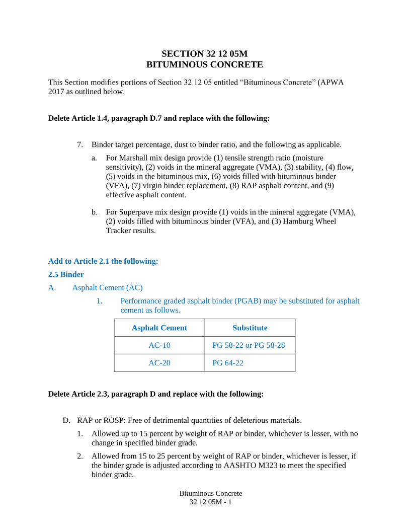
SECTION 32 12 05M
BITUMINOUS CONCRETE
This Section modifies portions of Section 32 12 05 entitled “Bituminous Concrete” (APWA
2017 as outlined below.
Delete Article 1.4, paragraph D.7 and replace with the following:
7. Binder target percentage, dust to binder ratio, and the following as applicable.
a. For Marshall mix design provide (1) tensile strength ratio (moisture
sensitivity), (2) voids in the mineral aggregate (VMA), (3) stability, (4) flow,
(5) voids in the bituminous mix, (6) voids filled with bituminous binder
(VFA), (7) virgin binder replacement, (8) RAP asphalt content, and (9)
effective asphalt content.
b. For Superpave mix design provide (1) voids in the mineral aggregate (VMA),
(2) voids filled with bituminous binder (VFA), and (3) Hamburg Wheel
Tracker results.
Add to Article 2.1 the following:
2.5 Binder
A. Asphalt Cement (AC)
1. Performance graded asphalt binder (PGAB) may be substituted for asphalt
cement as follows.
Asphalt Cement Substitute
AC-10 PG 58-22 or PG 58-28
AC-20 PG 64-22
Delete Article 2.3, paragraph D and replace with the following:
D. RAP or ROSP: Free of detrimental quantities of deleterious materials.
1. Allowed up to 15 percent by weight of RAP or binder, whichever is lesser, with no
change in specified binder grade.
2. Allowed from 15 to 25 percent by weight of RAP or binder, whichever is lesser, if
the binder grade is adjusted according to AASHTO M323 to meet the specified
binder grade.

TYP. CURB & GUTTER
SIDE ELEVATION
6' M
IN. D
EPTH
NO
TE 4
FRONT ELEVATION
NOTE: GRADUALLY SLOPE APRON FROM FLOW LINE OFCURB & GUTTER DOWN TO TOP OF GRATE.
PIPEDOUTLET
MIN. 12"
MIN. 8"APRON
SEDIMENT TRAP 12" MIN.WITHOUT OR 36" MIN. WITH
PRETREATMENT, FOLLOWMANUFACTURERS
RECOMMENDED DESIGN DEPTH
MIN.2'
COVER
MIN. 6"
2'
NON-SHRINK GROUT
15" MIN. DIA.OR 18" AS
NECESSARY
3'
6" - 12"CONCRETE COLLAR ALL
AROUND THE OUTSIDE OFPIPE AT BOX CONNECTION.
NOTE:1. FOR GRATE & FRAME DETAILS SEE D.&L. SUPPLY CATALOG #I-3518 OR EQUIVALENT.2. REQUIRED STAMPED HOOD, "DRAINS TO RIVER OR LAKE" WITH FISH LOGO.3. ALL BOXES AND FRAMES MUST SUPPORT A HS-20 LOADING.4. REFER TO THE APPROVED PROJECT PLANS FOR PIPE SIZE, LOCATION, SEDIMENT DEPTH, PRETREATMENT AND
OTHER STRUCTURE DESIGN REQUIREMENTS.4.1. 15" DIA. PIPE LATERAL, MINIMUM DEPTH FROM OUTLET OF PIPE FLOW LINE TO FLOOR OF INLET BOX IS
3.75 FEET OR DEEPER. FOLLOW PRETREATMENT MANUFACTURERS RECOMMENDATIONS. MIN. BOXINSIDE DEPTH IS 6 FEET.
4.2. 18" DIA. PIPE AS NECESSARY, MINIMUM DEPTH FROM OUTLET OF PIPE FLOW LINE TO FLOOR OF INLETBOX IS 4.5 FEET OR DEEPER. FOLLOW PRETREATMENT MANUFACTURERS RECOMMENDATIONS. MIN.BOX INSIDE DEPTH IS 7 FEET.
4.3. *24" DIA. SPECIAL APPROVAL IS REQUIRED IN ADDITION TO INLET STRUCTURE DESIGN. THE MINIMUMDEPTH FROM OUT LET PIPE FLOW LINE TO FLOOR OF INLET BOX IS 6.0 FEET. FOLLOW PRETREATMENTMANUFACTURERS RECOMMENDATIONS.
5. A SNOUT IS REQUIRED AT EVERY INLET UNLESS AN ALTERNATE PRETREATMENT PLAN HAS BEEN APPROVED.
HOOD MIN. 6"
DRAINS TO RIVER OR LAKE
DRAIN
S TO RIVER O
R LAKE
3' 4'
CURB & GUTTER
PRETREATMENT WITHMAINTENANCE ACCESSREQUIRED.
PLANTER AREA
PLANTER AREA
VACUUM BREAK
MIN. 2" DROP
SET INSIDE OF BOX TOBACK OF CURB FLOW LINE
TYPE D&L I-3518GRATE OR EQUIVALENT
LIP OF CURB
TBC
FLMIN. 8"APRON
MIN. 1'
PRE-CAST CURB FACEAND INLET BOX
REVISED DATE: 10/07/19
STANDARD DETAIL
P-315aNOT TO SCALE
STANDARD DETAIL
SHEET 1 OF 1

CURB & GUTTER
SIDE ELEVATION
6' M
IN. D
EPTH
NO
TE 4
2"
6" TYPICAL
FRONT ELEVATION
SEDIMENT TRAP 12" MINWITHOUT OR 36" MIN WITHPRETREATMENT, FOLLOW
MANUFACTURERSRECOMMENDED DESIGN DEPTH
3" MIN.
DRAINS TO RIVER OR LAKE
MIN. 8"APRON12" MIN
15" MIN. DIA.OR 18" AS
NECESSARY
3'
6" - 12"CONCRETE COLLAR ALL
AROUND THE OUTSIDE OFPIPE AT BOX CONNECTION.
TYPE D&L I-3518GRATE OR EQUIVALENT
PIPEDOUTLET
#4 REBAR12" O.C.
PLANTER AREA
PLANTER AREA
NOTE: GRADUALLY SLOPE APRON FROM FLOW LINE OFCURB & GUTTER DOWN TO TOP OF GRATE.
MIN. 6"
NON-SHRINK GROUT
HOOD MIN. 6"
PRETREATMENT WITHMAINTENANCE ACCESSREQUIRED.
VACUUM BREAK
MIN. 2" DROP
MIN. 1'
SET INSIDE OF BOX TOBACK OF CURB FLOW LINE
MIN.2'
COVER
LIP OF CURB
TBC
FLMIN. 8"APRON
NOTE:1. FOR GRATE & FRAME DETAILS SEE D.&L. SUPPLY CATALOG #I-3518 OR EQUIVALENT.2. REQUIRED STAMPED HOOD, "DRAINS TO RIVER OR LAKE" WITH FISH LOGO.3. ALL BOXES AND FRAMES MUST SUPPORT A HS-20 LOADING.4. REFER TO THE APPROVED PROJECT PLANS FOR PIPE SIZE, LOCATION, SEDIMENT DEPTH, PRETREATMENT
AND OTHER STRUCTURE DESIGN REQUIREMENTS.4.1. 15" DIA. PIPE LATERAL MIN. BOX INSIDE DEPTH IS 6 FEET AND FOLLOWS PRETREATMENT
MANUFACTURERS RECOMMENDATIONS.4.2. 18" DIA. PIPE AS NECESSARY. BOX INSIDE DEPTH IS 7 FEET AND FOLLOWS PRETREATMENT
MANUFACTURERS RECOMMENDATIONS.4.3. *24" DIA. SPECIAL APPROVAL IS REQUIRED IN ADDITION TO INLET STRUCTURE DESIGN. THE MIN.
DEPTH FROM OUTLET PIPE FLOW LINE TO FLOOR OF INLET BOX IS 6.0 FEET. FOLLOWPRETREATMENT MANUFACTURER'S RECOMMENDATIONS
5. A SNOUT IS REQUIRED AT EVERY INLET UNLESS AN ALTERNATE PRETREATMENT PLAN HAS BEENAPPROVED.
CAST-IN-PLACE CURBFACE AND INLET BOX
REVISED DATE: 09/26/19
STANDARD DETAIL
P-315bNOT TO SCALE
STANDARD DETAIL
SHEET 1 OF 1

FRO
NT
ELEV
ATIO
NSI
DE
ELEV
ATIO
N
MIN
. 6"
2'
6' MIN. DEPTH NOTE 4
12"
MIN
.
NO
N-S
HRI
NK
GRO
UT
15"
MIN
. DIA
.O
R 18
" AS
NEC
ESSA
RY
PIPE
DO
UTL
ET
3'3'
IF B
OXE
S AR
E N
OT
FLU
SH, U
SE A
15"
MIN
. DIA
. PIP
E TO
CO
NN
ECT
BOXE
S.
FLO
W L
INE
OF
CON
NEC
TIN
G P
IPE
MU
ST H
AVE
AT L
EAST
A 3
6 IN
CHM
IN. S
EDIM
ENT
TRAP
OR
HIG
HER
TO M
ATCH
PIP
ED O
UTL
ET F
LOW
LIN
E EL
EVAT
ION
.
6" -
12"
CON
CRET
E CO
LLAR
ALL
ARO
UN
D T
HE
OU
TSID
E O
FPI
PE A
T BO
X CO
NN
ECTI
ON
.
NO
N-S
HRI
NK
GRO
UT
PLAN
TER
AREA
DRAINS TO RIVER OR LAKE
DRA
INS
TO R
IVER
OR
LAKE
DRA
INS
TO R
IVER
OR
LAKE
PLAN
TER
AREA
SED
IMEN
T TR
AP 1
2" M
IN. W
ITHO
UT
OR
36"
MIN
. WIT
H P
RETR
EATM
ENT,
FOLL
OW
MAN
UFA
CTU
RERS
RECO
MM
END
ED D
ESIG
N D
EPTH
8" M
IN.
APRO
N
PRET
REAT
MEN
T W
ITH
MAI
NTE
NAN
CE A
CCES
SRE
QU
IRED
.
VACU
UM
BRE
AKMIN
. 2"
DRO
P
SET
INSI
DE
OF
BOX
TOBA
CK O
F CU
RB F
LOW
LIN
E
TYPE
D&
L I-3
518
GRA
TE O
R EQ
UIV
ALEN
T
8" M
IN.
APRO
N
MIN
. 1'
HO
OD
MIN
. 6"
NO
TE:G
RAD
UAL
LY S
LOPE
APR
ON
FRO
M F
LOW
LIN
E O
FCU
RB &
GU
TTER
DO
WN
TO
TO
P O
F G
RATE
.
FL
LIP
OF
CURB TB
CH
OO
D M
IN. 6
"
MIN
.2'
COVE
R
TYP.
CU
RB&
GU
TTER
NO
TE:
1.FO
R G
RATE
& F
RAM
E D
ETAI
LS S
EE D
.&L.
SU
PPLY
CAT
ALO
G #
I-351
8 O
R EQ
UIV
ALEN
T.2.
REQ
UIR
ED S
TAM
PED
HO
OD
, "D
RAIN
S TO
RIV
ER O
R LA
KE" W
ITH
FIS
H L
OG
O.
3.AL
L BO
XES
AND
FRA
MES
MU
ST S
UPP
ORT
A H
S-20
LO
ADIN
G.
4.RE
FER
TO T
HE
APPR
OVE
D P
ROJE
CT P
LAN
S FO
R PI
PE S
IZE,
LO
CATI
ON
, SED
IMEN
T D
EPTH
, PRE
TREA
TMEN
T AN
D O
THER
STRU
CTU
RE D
ESIG
N R
EQU
IREM
ENTS
.4.
1.15
" D
IA. P
IPE
LATE
RAL,
MIN
IMU
M D
EPTH
FRO
M O
UTL
ET O
F PI
PE F
LOW
LIN
E TO
FLO
OR
OF
INLE
T BO
X IS
3.7
5 FE
ET O
RD
EEPE
R. F
OLL
OW
PRE
TREA
TMEN
T M
ANU
FACT
URE
RS R
ECO
MM
ENDA
TIO
NS.
MIN
. BO
X IN
SIDE
DEP
TH IS
6 F
EET.
4.2.
18"
DIA
. PIP
E AS
NEC
ESSA
RY, M
INIM
UM
DEP
TH F
ROM
OU
TLET
OF
PIPE
FLO
W L
INE
TO F
LOO
R O
F IN
LET
BOX
IS 4
.5 F
EET
OR
DEE
PER.
FO
LLO
W P
RETR
EATM
ENT
MAN
UFA
CTU
RERS
REC
OM
MEN
DATI
ON
S. M
IN. B
OX
INSI
DE D
EPTH
IS 7
FEE
T.4.
3.*2
4" D
IA. S
PECI
AL A
PPRO
VAL
IS R
EQU
IRED
IN A
DD
ITIO
N T
O IN
LET
STRU
CTU
RE D
ESIG
N. T
HE
MIN
IMU
M D
EPTH
FRO
MO
UT
LET
PIPE
FLO
W L
INE
TO F
LOO
R O
F IN
LET
BOX
IS 6
.0 F
EET.
FO
LLO
W P
RETR
EATM
ENT
MAN
UFA
CTU
RER'
SRE
COM
MEN
DAT
ION
S.5.
A SN
OU
T IS
REQ
UIR
ED A
T EV
ERY
INLE
T U
NLE
SS A
N A
LTER
NAT
E PR
ETRE
ATM
ENT
PLAN
HAS
BEE
N A
PPRO
VED
.
DOUBLE PRE-CAST CURBFACE AND INLET BOX
REVISED DATE: 09/26/19
STANDARD DETAIL
P-315cNOT TO SCALE
STANDARD DETAIL
SHEET 1 OF 1


SLOPE OUT TO STREET
DRAINAGE KEPT
WITHIN PROPERTY,
NOT DISCHARGED
ONTO NEIGHBORING
PROPERTIES.
R.D.
R.D.
R.D.
R.D.
LEGEND
B.P. - BREAK POINT
T.B.C. - TOP BACK OF CURB
G.F.- GARAGE FLOOR
L.H.F.- LOWEST HABITABLE FLOOR
F.F. - FINISH FLOOR
F.G. - FINISH GRADE
E.G. - EXISTING OR PRE-CONSTRUCTION GRADE
FLOW DIRECTION
BENCH MARK (T.B.C. OR PERMANENT FEATURE)
R.D. - ROOF DRAIN ( DISCHARGE BEYOND FOOTING)
REFER TO SHEET P-390 2 OF 2 FOR
ADDITIONAL NOTES
REFER TO SHEET P-391 FOR LOT
GRADING PROFILES
LANDSCAPING BERM
T.B.C.
ELEV
SLOPE OUT TO STREET
F.F.
L.H.F.
R.D.
R.D.
R.D.
R.D.
SOILS TEST
HOLE LOCATION
SEE NOTE #2.D
2% MIN. SLOPE
AWAY FROM
STRUCTURE
FOR MIN. OF 10'
E.G.
F.G.
F.G.
SIDEWALK
ELEV
G.F.
E.G.
F.G.
E.G.
F.G.
T.B.C.
ELEV
SIDEWALK
ELEV
E.G.
F.G.
E.G.
F.G.
B.P.
F.G.
T.B.C.
ELEV
E.G.
F.G.
SIDEWALK
ELEV
E.G.
F.G.
B.P.
E.G.
F.G.
E.G.
F.G.
SIDEWALK
ELEV
T.B.C.
ELEV
E.G.
F.G.
F.G.
F.G.
F.G.
F.F.
L.H.F.
G.F.
2% MIN. SLOPE
AWAY FROM
STRUCTURE
FOR MIN. OF 10'
T.B.C.
ELEV
T.B.C.
ELEV
B.P.
SOILS TEST
HOLE LOCATION
SEE NOTE #2.D
TYPE 1 LOT
TYPE 2 LOT
STANDARD DETAIL
P-390
NOT TO SCALE
SHEET 1 OF 2
LOT GRADING PLANREVISED DATE: 10/8/2019

Lot grading plan notes
1. GENERALA.Per Section 18.03.080, Provo City Code, it shall be the responsibility of the property owner to ensure
that the private drainage generated within the private property is adequately handled and does notcreate a nuisance on neighboring properties. Provide a site grading plan with existing and final elevationinformation.
2. EXECUTIONA.Drain as much surface flows, especially hard (impervious) surfaces, as possible out to the street fronting
the lot. This includes the following; all front of building, as much roof as possible, drive way, walks, andso forth. Any areas unable to be sloped to the street shall be addressed within own lot boundaries andnot discharged into any neighboring properties.
B. Garage floor (G.F.) shall follow the requirements detailed in Provo standard drawing P-394.C. Identify existing spot elevations for at least 5-6 different locations, especially along the property
boundary to ensure adequate tie-in to neighboring properties. Provide final grade elevations for samespots, significant grade changes, and other locations necessary to show intended grading design.
D. Any time there is a lower level in a structure a soils engineer letter may be requested to determine theground water elevations relative to the basement floor. Refer to the Storm Drainage Systems Designand Management Manual for requirements for lowest habitable floor elevations in relation togroundwater. Identify all test hole locations and depths relative to the benchmark (i.e. top of curb atproperty corner, or other permanent feature).
LOT GRADING PLANNOTES
REVISED DATE: 10/8/19
STANDARD DETAIL
P-390
NOT TO SCALE
STANDARD DETAIL
SHEET 1 OF 2

TY
PE
1 LO
T
TY
PE
2 LO
T
PLAN
REQ
UIR
EMEN
TS
1.EX
ISTI
NG
AND
PRO
POSE
D GR
ADES
(LAB
EL A
ND
EXTE
ND
PAST
PRO
PERT
Y LI
NES
).
2.EL
EVAT
ION
S O
N K
EY S
TRU
CTU
RAL
POIN
TS, W
ALLS
, SLA
BS, D
RIVE
WAY
S, G
ARAG
E, E
TC.
3.RE
TAIN
ING
WAL
L LO
CATI
ON
S, A
ND
ENGI
NEE
RED
DESI
GN IF
REQ
UIR
ED.
4.O
THER
REQ
UIR
EMEN
TS A
S PE
R GE
OTE
CHN
ICAL
INVE
STIG
ATIO
N R
EPO
RTS
IF R
EQU
IRED
.
LOT GRADINGPROFILES
REVISED DATE: 10/8/19
STANDARD DETAIL
P-391
NOT TO SCALE
STANDARD DETAIL
SHEET 1 OF 1

STO
RM M
AIN
LIN
E
STAMP "L" IN CURBOR APPROVED ALTERNATIVE MARKINGABOVE LOT DRAIN
45° BEND* 4" SOLID PVC*FROM MAIN TO CLEAN OUTAT STRUCTURE.
45° BEND*
STORM MAIN LINE
GROUND
SURFACE
INSTALL UTILITY WARNING TAPE2 FEET ABOVE PIPE
PIPE ZONE MATERIAL(P-255)
PROFILE
PLAN VIEW
FLOW
ABOVE PIPE SPRING LINE, USEAN INSERTA TEE OR EQUIVALENTFOR MAIN CONNECTION.FLUSH MOUNT ONLY,NO PROTRUSIONS INTO MAIN.
* USE TYPE SDR 35 PVC AND THE COLORWHITE FOR ALL LOT DRAIN LATERAL PIPING
4" SWEEPELBOW*
4" PVCSEPARATION
PIPE*
CLEANOUT WITH GRATEDLANDSCAPE CAP LOCATED
AT LEAST 12" ABOVE STREETGUTTER FLOW LINE.
LOT DRAIN PUMP W/BACKFLOW PREVENTER
SEAL AROUND CONNECTIONFROM PUMP OUTLET HOSE
PERFORATED 4" PVC LOT DRAIN,OR APPROVED EQUIVALENT WITH
COMPARABLE FLOW CAPACITY
PERFORATED 4" PVC LOT DRAIN, ORAPPROVED EQUIVALENT WITHCOMPARABLE FLOW CAPACITY
- DO NOT USE WITHOUT PRIOR APPROVAL -
LOWESTHABITABLE
FLOOR(SEE SHEET
3 OF 3,GENERALNOTE A)
2% MINSLOPE
5' FROMSTRUCTURE
2% MINSLOPE
45°
ONLY STORM WATERALLOWED DISCHARGESINTO A DRAINAGE SYSTEM,PROVO CODE 18.02.020.
DATE: 10/07/2019
STANDARD DETAIL
NOT TO SCALE
STANDARD DETAIL
SHEET 1 OF 3
STAMP "L" IN CURBOR APPROVED ALTERNATIVE MARKINGABOVE LOT DRAIN
45° BEND*
45° BEND*
STORM MAIN LINE
GROUND
SURFACE
INSTALL UTILITY WARNING TAPE2 FEET ABOVE PIPE
PROFILE
PLAN VIEW
ABOVE PIPE SPRING LINE, USEAN INSERTA TEE OR EQUIVALENTFOR MAIN CONNECTION.FLUSH MOUNT ONLY,NO PROTRUSIONS INTO MAIN.
* USE TYPE SDR 35 PVC AND THE COLORWHITE FOR ALL LOT DRAIN LATERAL PIPING
PERFORATED 4" PVC LOT DRAIN,OR APPROVED EQUIVALENT WITH
COMPARABLE FLOW CAPACITY
ONLY STORM WATERALLOWED DISCHARGESINTO A DRAINAGE SYSTEM,PROVO CODE 18.02.020.
45° WYE* ORFERNCO STRONG BACK SERIESRIDGED METAL COUPLING OREQUAL.
PERFORATED 4" PVC LOT DRAIN, ORAPPROVED EQUIVALENT WITHCOMPARABLE FLOW CAPACITY
4" ABSBACKFLOWPREVENTER
CLEANOUT WITH GRATEDLANDSCAPE CAP LOCATED
AT LEAST 12" ABOVE STREETGUTTER FLOW LINE.
DIRECTLY BEHIND BACKFLOW PREVENTER
LOWESTHABITABLE
FLOOR(SEE SHEET
3 OF 3,GENERALNOTE A)
2% MINSLOPE
STO
RM M
AIN
LIN
E
- DO NOT USE WITHOUT PRIOR APPROVAL -
5' FROMSTRUCTURE
2% MINSLOPE
45°
PIPE ZONE MATERIAL(P-255)
4" SOLID PVC*FROM MAIN TO CLEAN OUTAT STRUCTURE.
FLOW
DATE: 10/07/2019
STANDARD DETAIL
NOT TO SCALE
STANDARD DETAIL
SHEET 2 OF 3

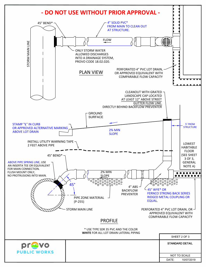
Lot Drain Lateral
1. GENERALA.Standard Drawings P-392a and P-392b may be used under the following conditions:
A.A. Lot drains are sometimes required by the IBC to drain backfilled areas aroundbuildings in areas with tight native soils . Lot drains are not intended to drain highgroundwater. The lowest habitable floor is recommended to be a minimum of 4feet above groundwater elevation. Provo City may require a site specificgeotechnical report identifying groundwater elevations and minimum FFelevations, to be reviewed and approved by the City Engineer or their designee.
A.B. Standard Drawing P-392a - The top of the landscape grate on the separation pipeshall be a minimum of 12 inches above the gutter flow line.
A.C. Standard Drawing P-392b - This drawing can only be used if (a) the storm drainmain is designed to convey the City design storm with the HGL below top of pipe,AND (b) the lowest habitable floor is a minimum of 2 feet above the top of stormdrain main at the lot drain connection. Otherwise, P-392a must be used.
B. It is unlawful for any person to cause or allow the discharge into a water body orstorm drainage system, either directly or indirectly, of any substance not comprisedentirely of storm water, refer to Provo City code 18.02.020 for prohibited discharges.
C. Minimum distance between lot drain connections to the storm main shall be 4 feet.D.Minimum required grade of lot drain is 2%.E. Clean-outs on lateral shall be installed at a minimum every 100 feet and wherever
there is a change in slope, direction or bend in pipe and within 5 feet from structure.F. If building construction is not imminent, terminate at a clean-out a minimum of 12
feet inside the property line. Cap and mark white for future connection.
2. PRODUCTSA.Lot drains shall use type SDR 35 PVC. The color of the pipe and fittings shall be white.B. Base Course: Untreated base course, APWA Section 32 11 23. Do not use gravel as a
base course without ENGINEER's permission.C. Backfill: Common fill, PROVO Section 31 05 13M. Maximum particle size 2-inches.D.Pipe zone: Gravel, Provo Section 31 05 13M.E. Lot drain mainline connections: 45 degree bend and Inserta Tee or equivalent.
3. EXECUTIONA.Before installation, secure acceptance by ENGINEER for all pipe, fittings, and
couplings to be used.B. Core and remove plug from storm main. Do not break into storm main for connection.C. Use an Inserta Tee or equivalent for a water tight connection at storm main.
Protrusion into storm main pipe past inner wall is not allowed.D. CONTRACTOR shall have ALL connections inspected and surveyed by Provo City
before backfilling.E. Provide backfill and surface restoration per Plan P-255.
DATE: 10/07/2019
STANDARD DETAIL
NOT TO SCALE
STANDARD DETAIL
SHEET 3 OF 3


SIDE VIEW FRONT VIEW
MAST ARM LENGTH (VARIES)
20'
2' M
IN
TELECOMMUNICATION LINES AREREQUIRED TO BE 2 FEET MINIMUMABOVE THE EDGE OF THE SIGNALHEAD.
5' MIN
TELECOMMUNICATION LINES AREREQUIRED TO BE 5 FEET MINIMUM
BEHIND THE SIGNAL HEAD.
NOTE:THIS STANDARD IS TO BE FOLLOWED AT ALL CURRENT AND FUTURE SIGNALIZED INTERSECTIONS.
OVERHEAD UTILITYLOCATION
STANDARD DETAIL
P-915
REVISED DATE: 10/14/2019
NOT TO SCALE
SHEET 1 OF 1
2020

CULINARY WATER SYSTEMS
1. WATER MAIN LINE UPSIZING OR EXTENSIONS
A. The developer of a project which requires the extension or upsizing of water main
lines shall pay the cost of such work.
B. All subdivisions shall have a complete water distribution system installed before
such subdivisions are accepted by the City.
a. The design and construction of such a water distribution system shall meet all
applicable standards and be approved prior to installation.
b. The developer shall install the water distribution system at the developer’s
own expense for all water mains which are necessary to provide all required
water per State and City design standards. Minimum static pressure at the
point of use shall be 50 psi. Maximum shall be 120 psi.
c. The system shall include a properly looped feed from the nearest adequately
supplied locations in the City water distribution system. Provo City will use a
hydraulic model where required by State Code to verify that the capacity for
fire flow and water demand as specified in the project plans are available. The
proposed system shall be modified to comply with the model findings.
d. If the Director requires increased capacity above that required for the project,
the developer may be eligible for reimbursement for the difference in material
cost between the main required for the development and the larger diameter
main actually installed.
C. When any street is to be paved from curb to curb with a permanent type of
pavement, an eight (8) inch or larger water main shall be installed in that street
prior to the paving of the street. The cost of installation of such water main shall
be borne by the developer.
D. If a person installs a water main line extension to serve a parcel, said main line
extension shall extend completely across the parcel of property being developed.
E. A developer who pays the cost of an off-site water main line extension may have
the right of reimbursement described in Provo City Code Chapter 10.02.050.
2. CULINARY WATER MAIN STANDARDS
A. All water system installation and design must conform to Provo City’s Water
System Master Plan and all applicable state administrative rules, particularly
R309-550.
a. Minimum allowable water main diameter shall be eight inches (8”) in low
and medium density residential areas.

b. Minimum allowable water main diameter shall be twelve inches (12”) in all
other areas.
c. Main lines larger than the minimums shown above may be required if
necessary for fire flow or pressure. Developer shall be responsible for an
upsize based on providing sufficient capacity for the development.
d. If the Master Plan requires a larger pipe size than described in paragraphs (a)
and (b), City may require the developer to install the larger size.
Reimbursement may be granted according to paragraph 1.D. of this section.
B. Waterline shall be Ductile Iron with polywrap, grease on bolts and #14 copper
tracer wire per Provo Standard Drawing P-594 and installed per AWWA Standard
C600-10.. PVC, HDPE, Steel, or other pipe material are not allowed unless
expressly permitted by the Public Works Division of Water Resources. All
construction and installation shall conform to standards referenced in R309-550-8
of the Utah Administrative Code.
C. Waterline should typically be installed within the street section in the location
shown on Provo Standard Drawing P-914.
D. Provide a minimum of ten (10) feet horizontal clearance between a water and
sewer edge to edge per Utah Administrative Code R317-3-2 and R309-550-7.
a. Where a water main and a sewer line must cross, the water main shall be
at least 18 inches above the sewer line. Separation distances shall be
measured edge-to-edge (i.e. from the nearest edges of the facilities).
b.Water mains and sewer lines shall not be installed in the same trench.
c. Where local conditions make it impossible to install water or sewer lines
at separation distances required by subsection (a), the sewer pipes are in
good condition, and there is not high groundwater in the area, it may be
acceptable if the design includes a minimum horizontal separation of 6
feet and a minimum vertical clearance of 18 inches with the waterline
being above. In order to determine whether the design is acceptable, the
following information shall be submitted as part of the plans for review.
i. reason for not meeting the minimum separation standard;
ii. location where the water and sewer line separation is not being
met;
iii. horizontal and vertical clearance that will be achieved;
iv. sewer line information including pipe material, condition, size,
age, type of joints, thickness or pressure class, whether the pipe is
pressurized or not, etc.;

v. water line information including pipe material, condition, size, age,
type of joints, thickness or pressure class, etc.;
vi. ground water and soil conditions; and,
vii. any mitigation efforts.
D.E.
F. Minimum cover required shall be 48 inches (48”).
G. All new water infrastructure shall be pressure tested by maintaining 200 psi for
two hours.
H. All materials that may come in contact with drinking water, including pipes,
gaskets, lubricants and O-Rings, shall be ANSI-certified as meeting the
requirements of ANSI/NSF Standard 61, Drinking Water System Components -
Health Effects. To permit field-verification of this certification, all components
shall be appropriately stamped with the NSF logo.
E.I. Pipe, joints, fittings, valves, and fire hydrants shall conform to ANSI/NSF
Standard 61, and applicable sections of AWWA Standards C104-A21.4-08
through C550-05 and C900-07 through C950-07.
3. VALVES
A. Valves shall be provided in all intersections and shall equal number of legs.
B. Valves shall be located a minimum of three feet (3’) off a tee or cross.
C. All valves larger than 12 inch (12”) shall be butterfly design.
D. Provide concrete collars on valve boxes at ¼” below finished asphalt.
E. Place valves at intersections per Provo Standard Drawing P-914.
4. WATER SERVICES
A. No service line connections shall be made to Provo City’s water distribution
system or to main water lines on private property without authorization. The party
making the connection shall be required to obtain a permit for the same and to pay
the fees associated with that permit as shown on the Consolidated Fee Schedule.
B. Water taps on public or private mains shall be installed by a qualified and licensed
plumber or a pre-qualified utility contractor and inspected by the City.
C. Minimum size shall be one inch (1”) diameter for service lines and meter yokes.
D. Engineering calculations shall be required to show that meter size is adequate to
meet demand for any uses other than detached single family residential or
townhomes.

E. No common use water services shall be allowed unless approved by the Water
Resources Director.
a. Service lines must be so arranged that the supply to each separate house or
premises are controlled by a separate valve, placed within and near the line of
the street curb.
b. Common use water services shall be eliminated as redevelopment of the site
occurs, or if repair or replacement is needed. The construction or repair cost
will be the responsibility of the Owner.
c. Master meter(s) or combined building meters may be allowed for private
developments if approved by the Water Resources Director. All lines within
the private development shall be private including those from the private
mainline to the meter. The developer shall provide the City with an agreement
defining who is responsible for maintenance and show the lines as private on
the plat and utility plans. Individual shutoffs located near the curb are required
for each unit.
d. Legal and physical access shall be provided to all meters.
d.e. All service lines shall be capped downstream of the meter box until connected
for service.
5. ABANDONDED SERVICE LINES
A. Whenever a water service line is abandoned in favor of a different service line,
the old service line shall be disconnected from the main line and the old service
tap shall be plugged at the main line. The cost of all such work shall be the
responsibility of the owner of the property being serviced by the new water
service line. Any work described in this Section shall be inspected by Provo City
before backfilling.
6. FIRE HYDRANTS
A. Provide minimum fire flow required by the Uniform Fire Code for proposed
structures and fire flow calculations at all hydrant locations. Unless project
specific information is provided, the following will be assumed:
Provo City Minimum Operational and Performance Criteria for Planning and Design
Component Criteria Fire Flow Requirements (flow [gpm] @ duration [hours]) a
Single-Family Residential 1,500 gpm @ 2 hrs
Multi-Family Residential 2,500 gpm @ 2 hrs
Commercial 3,000 gpm @ 3 hrs (with approved automatic sprinkler system)
Institutional (schools, hospitals, etc.) 4,000 gpm @ 4 hrs (with approved automatic sprinkler system
Industrial/Business Park 4,000 gpm @ 4 hrs (with approved automatic sprinkler system)

Water Transmission Line Sizing (16-in in diameter or greater)
Max day plus Fire Flow or Peak Hour Demand Condition
Minimum Pressure, psi 35 psi (20 psi for fire flow)
Maximum Head Loss, ft per 1000 ft of pipe (ft/kft) 7 ft/kft
Maximum Velocity, ft per second (fps) 7 fps
Water Distribution Line Sizing (Less than 16-in in diameter)
Max day plus Fire Flow or Peak Hour Demand Condition
Minimum Pressure, psi 35 psi (20 psi for fire flow)
Maximum Head Loss, ft/k ft 10 ft/kft
Maximum Velocity, ft/sec 5 fps a Typical minimum flow will be verified by City on a case by case basis
B. Install fire hydrants per Provo Standard Drawing P-511.
a. Hydrants shall be connected to a minimum eight-inch (8”) main using a
minimum six-inch (6”) diameter pipe.
b. No bends are allowed on fire hydrant laterals.
c. No services shall be allowed on fire hydrant laterals.
C. Replace fire hydrant if the hydrant is to be moved.
D. Fire Hydrant spacing:
a. Shall not exceed three hundred feet (300’) in areas of multi-family dwellings,
commercial and manufacturing uses.
b. In single family dwelling use areas hydrant spacing shall not exceed five
hundred feet (500 ft).
c. Major roads shall have fire hydrants placed on both sides of the roadway to
provide for Fire Department access to such hydrants.
E. Place fire hydrant within 100 feet (100’) of the fire department connection (FDC).
F. Provide fire hydrants at the end of dead-end lines for flushing purposes.
G. Private fire service lines designed to provide fire protection to a building or
buildings shall be constructed according to Provo City Standards at the expense of
the owner of the building being serviced according to the following requirements:
a. Maintenance associated with such fire service lines shall also be at the
expense of said owner.
b. Water service lines and meters may be connected to fire service lines when
approved by the Director if the fire line is looped and said fire lines are
intended to provide water to the building being serviced by the fire service
line. In this case, the fire lines and service lines will be private and only
appurtenances inside the meter box will be maintained by the City.
c. Provide a valve on the mainline. Fire line after the valve shall be private.
d. Fire suppression system and hydrants are not allowed on the same line unless
the fire line is looped.
e. Provide approved backflow prevention.

7. WATER VAULTS/METER BOXES
A. Whenever a new service line is installed connecting any premises to an unmetered
private line which is supplied water from the water mains of Provo City, or
whenever a service pipe is connected directly to the water system of said City, a
water meter must be installed.
B. All water meters shall be installed in easily accessible locations.
C. No meter box shall be allowed in any street, driveway, driveway flare, or
sidewalk without express written permission of Provo City.
D. At the time of a significant remodel or new construction, existing services and
meter sets must be brought up to current standard with dual check valves in meter
yoke and new can. If the service line is damaged, deteriorated, or galvanized pipe,
the OWNER shall replace the water service from the mainline to the meter.
Splices between the mainline and meter yoke are not allowed so if a meter
location is changed to be farther from the mainline, a new service line from the
main to meter yoke is required.
E. Water meters shall be furnished and installed by Provo City.
F. Water meters shall not be installed until:
a. Proper demolition of old water lines and services has been completed or a
bond for such demolition has been received.
b. Newly installed main lines have been pressure tested, disinfected, and
approved and service lines, including meter boxes and appurtenances, have
been inspected and approved.
c. No meters shall be installed until all applicable fees have been paid including
water connection fees, impact fees and main line extension fees as
appropriate.
8. THRUST RESTRAINTS
A. Concrete thrust blocks:
a. Provide concrete thrust blocks at all taps, temporary dead ends and at the base
of all hydrants.
b. Place thrust blocks directly against undisturbed earth.
c. Provide bond breakers on all thrust blocks.
d. All other locations shall rely on restrained joints to handle thrust unless
directed otherwise by City
B. Joint Restraints:
a. The number of joints that need to be restrained back from thrust producing
fittings shall be determined by the design engineer and approved by the City.
9. BACKFLOW PREVENTION DEVICE

A. Install an approved backflow prevention device downstream of all meters larger
than 2-inch and ahead of all outside irrigation systems. The backflow prevention
device shall meet all requirements of Utah Administrative Rule R309-105 and the
International Plumbing Code.
B. Comply with City Standard Drawings.
C. Contact cross connection coordinator at (801) 852-6788 for inspection of the
backflow prevention devices other than dual check valves inside meter boxes.
10. WATER LINE LOOPING
A. Looping of water lines creates a vulnerability in the system; therefore, looping is
highly discouraged. All other alternatives should be investigated prior to
proposing looping, which should be the option of last resort.
B. If looping of water lines is approved by Provo, the Director may assess a fee for
shutting down the existing line and to provide for future maintenance of the loop.
The fee will vary based on the size of the line being looped.
11. EASEMENTS
A. Provide a minimum twenty feet wide (20’) public utility easement for all public
water mains installed outside of the street right of way or other City owned
property. Unless otherwise approved, the water line should be installed in the
center of the easement.
12. OTHER APPURTENANCES
A. Provide pressure reducing stations if required by Water Resources Director.
B. Air vacuum breakersrelief valves and blow-offs at high points may be required if
other means of air release are not provided. If used, air relief valves and blow-
offs shall comply with the following:
a. The open end of the air relief vent pipe from automatic valves shall be
provided with a #14 mesh, non-corrodible screen and a downward elbow,
and where possible, be extended to at least one foot above grade.
Alternatively, the open end of the pipe may be extended to as little as one
foot above the top of the pipe if the valve's chamber is not subject to
flooding, or if it meets the requirements of (7) Chamber Drainage.
b.Blow-offs or air relief valves shall not be connected directly to a sewer.
c. Adequate number of hydrants or blow-offs shall be provided to allow
periodic flushing and cleaning of water lines.

B.d. The air relief valve shall be installed in a manner to prevent it from
freezing. A shut-off valve shall be provided to permit servicing of an air
relief valve.
C. All booster proposed stations and storage tanks subject to Water Resources
Director approval and shall meet all the following requirements:
a. All booster stations and storage tanks shall be identified as part of the City’s
master plan and shall be designed to service large City areas and not
individual developments. Private booster stations are not allowed.
b. No booster stations shall be constructed without a storage tank of sufficient
size to meet all sizing requirements of Utah Administrative Code R309-510.
Said tank shall be located at an elevation sufficient to provide gravity flow to
its service area and shall be designed to work cooperatively with all other
components of the water source, storage and distribution system.
c. The booster station shall be located on a main with sufficient size and pressure
to provide the required flow without causing any part of the water system to
fail to meet pressure requirements.
D. Chambers, pits, or manholes containing valves, blow-offs, meters, or other such
appurtenances to a distribution system, shall not be connected directly to a storm
drain or sanitary sewer. Chambers shall be provided with a drain to daylight, if
possible. Where this is not possible, underground gravel-filled absorption pits
may be used if the site is not subject to flooding and conditions will assure
adequate drainage. Sump pumps may also be considered if a drain to daylight or
absorption pit is not feasible.

SANITARY SEWER SYSTEMS All Sanitary Sewer installation and design shall comply with Provo City’s Wastewater Collection
System Master Plan.
1. SEWER MAIN LINE UPSIZING OR EXTENSIONS
A. The developer of a project which requires the extension or upsizing of sewer main
lines shall pay the cost of such work.
B. All subdivisions shall have a complete sewer distribution system installed before
such subdivisions are accepted by the City.
a. The design and construction of such a sewer distribution system shall meet all
applicable standards and be approved prior to installation.
b. The developer shall install the sewer distribution system at the developer’s
own expense for all sewer mains which are necessary to provide all required
sewer per State and City design standards.
1. Design 8”-15” pipes to flow no more than Half Full at Peak Flow.
2. Design 18” and Larger Pipes to flow no more than 75% Full at Peak Flow.
3. Include inflow and infiltration in sizing calculations.
4. Provo City may use a sewer model to verify sewer capacity is available for
the proposed project as specified in the project plans. The proposed system
shall be modified to comply with the model findings and offsite
improvements may be required prior to development.
5. Ensure that transmission pipes sizes are sufficient for future growth in the
area per the most recent Provo City’s Wastewater Collection System
Master Plan. If the Master Plan requires a larger pipe than the
development, City may pay for the difference in material cost between the
size required for the development and the larger size.
C. When any street is to be paved from curb to curb with a permanent type of
pavement, an eight (8) inch or larger sewer main shall be installed in that street
prior to the paving of the street. The cost of installation of such sewer main shall
be borne by the developer.
D. If a person installs a sewer main line extension to serve a parcel of property, said
main line extension shall extend completely across the parcel of property being
developed.
E. A developer who pays the cost of an off-site sewer main line extension may have
the right of reimbursement described in Provo City Code Chapter 10.03.040.
2. SEWER PIPE MAIN STANDARDS
A. Minimum mainline size shall be 8” in diameter. Actual size of mainlines shall
provide adequate flow for current and future development.
B. Provide green PVC (polyvinyl Chloride) SDR 35 or approved equal.

C. Sewer mainlines and laterals shall be marked with a detectable green colored
locator tape.
D. Minimum depth of the sewer mainlines shall be seven (7) feet below finish grade.
In areas where basements are allowed, sewer mains shall be deep enough to
service basements.
E. Sewer mainline grades are as follows:
Minimum Sewer Main Pipe Slope*
8 inch sewer lines** 0.40%
10 inch sewer lines 0.28%
12 inch sewer lines 0.22%
15 inch sewer lines 0.15%
18 inch sewer line 0.12%
21 inch and larger sewer lines 0.10% * Sewer mains may not be upsized only for the purpose of installing at a flatter slope unless information is provided by the engineer showing that there is adequate scour volume to keep the line clean without increased maintenance. ** The first segment(s) of 8 inch sewer mains may be required to be placed at 1% min slope if there is not sufficient flow to provide adequate scour volume.
F. All sewers which are designed to flow at 10 feet per second or greater shall be
reviewed by City for approval or alternate design consideration. Suitable thrust
blocks, concrete anchors or equivalent restraints shall be provided per R317-3-2
of the Utah Code when pipe slopes are 10% or greater.
G. Horizontal clearance to any culinary water line shall be at least 10 feet (10’) edge
of pipe to edge of pipe per R309-550 and R317-3-2.
a. Utilities crossing sewer mains shall cross as close to a right angle as possible.
b. Provide a minimum vertical clearance of eighteen inches (18”) between water
and sewer with water main lines and service above the sewer measured from
the outside of the pipes.
3. MANHOLE DESIGN STANDARDS
A. Manholes shall conform to Provo Standard Drawing P-411.
B. Depth transitions shall occur between manholes. Drop manholes are discouraged
and may only be used with explicit written approval and shall conform to Provo
Standard Drawing P-433.
C. Sewer manholes shall be installed:
a. At a maximum spacing of four hundred (400) feet.
b. At all changes in grade, size or alignment, and at all intersections with other
mainlines.
c. At the end of main lines (no cleanouts allowed on mainlines).
d. All six-inch (6”) and larger laterals on commercial or multi-family laterals
require a manhole at the connection to the public main.

D. Sewer manholes shall be sized based on the following:
a. Five (5) foot Diameter manholes required at three-way manholes, 90° bends,
over 15” and 18” pipes, manholes over 10’ deep, and in manholes with over
one feet of foot of drop in across manhole.
b. Six (6) foot Diameter manholes required over pipes 24” and greater, and at
three-way manholes where the deflection exceeds 90° and height of manhole
exceeds 16'.
4. ABANDONMENT OF SEWER LATERALS
A. Whenever an existing sewer lateral(s) is abandoned in favor of a new lateral, the
Owner shall disconnect the existing sewer lateral from the main and plug the
lateral tap into the main. All costs associated with labor and material for such
work shall be the responsibility of the property owner causing the lateral to be
abandoned. All work shall be inspected by Provo City before backfilling.
5. SEWER LATERAL DESIGN STANDARDS
A. Sewer taps will be performed by the contractor and inspected by a City Inspector.
a. Sewer taps into an existing eight (8) inch main shall not be greater than four
(4) inches.
1. Direct nose-on connections may only be used when connecting to an
existing mainline. The installation must be inspected and a saddle used
when warranted.
2. Connections to new mains shall be with a wye and a forty-five degree
(45⁰) bend.
b. Minimum distance between connections shall be four feet.
c. Sewer laterals on end manholes and in cul-de-sacs may be allowed to tap into
a manhole directly with approval by the City. Provide formed base to direct
flow through manhole. shall connect to sewer main lines and not discharge
into manholes.
B. At the time of new construction, significant remodel or change of use, reuse of
existing laterals may be allowed for use only if the following conditions are met:
a. The existing lateral is of sufficient size and slopes for the proposed use.
b. The existing lateral is in good condition, free from damage, bellies, leaks, or
deviations in slope.
c. If the above criteria cannot be met the Owner shall abandon the existing later
at the main and provide a new lateral that meets all current Provo Standards
and Specifications.
C. Allowable sanitary sewer lateral pipe material shall be as follows:
a. ABS (Acrylonitrile-Butadiene-Styrene) schedule 40, black in color. For use in
sewer laterals only.

b. PVC (Polyvinyl Chloride) SDR 35 or other approved wall thickness for
laterals (green in color).
D. Minimum lateral size shall be as follows:
a. Single family residential: four (4) inches in diameter with 2% minimum slope.
b. Individual lateral serving five (5) or fewer residential equivalent units: four
(4) inches in diameter with a minimum slope of 2%.
c. All other uses: minimum six inches (6”) diameter with a slope of 2%. A 1%
minimum slope may be used if approved as part of the City review.
1. The sewer lateral size shall be based on actual project flows, but in no case
shall the lateral be less than six inches (6”) in diameter.
E. The policy of the City regarding the number of separate service laterals for
residential and commercial structures is as follows:
a. Each separate lot, parcel, dwelling unit, building, house, business or premises
shall be served by an individual lateral except as allowed in paragraph (c).
b. For one- and two-family dwelling structures, a separate service lateral for each
dwelling unit is required.
c. For multiple-family dwelling structures, stacked dwelling units, or
commercial structures separate service laterals for each unit shall be the
general rule. However, where design dictates otherwise, a common lateral for
multiple units (or fewer laterals than the number otherwise specified) may be
permitted where the applicant provides adequate documentation, including
signed and stamped engineering calculations, and guarantees to assure
adequacy of sewer/wastewater collection and responsibility for payment and
maintenance. Easements may also be necessary where common laterals cross
property lines. In any such case, the Water Resources Director has sole
discretion to permit or reject a reduction in the required number of service
laterals accordingly.
d. Common sewer laterals approved under paragraph (c) shall be have a
minimum diameter of six (6) inches for all laterals serving more than five
residential equivalent units.
F. Sewer laterals shall not be allowed to connect into any private sewer system
without permission from the owner of said system.
G. Cleanouts shall be required at a minimum of every 100 feet (100’) and at bends
forty-five degrees (45°) or greater. All laterals shall have at least one cleanout.
6. PRETREATMENT
A. Pretreatment
a. Pretreatment will generally be required for each use producing excessive
grease, sand, oil or sewer load different from a standard residential unit.

b. All covered parking lots, car washes, restaurants, auto shops and interior floor
drains that are subject to receipt of sand, silts, chemicals, petroleum products,
or other contaminants must have a grease trap, sand/oil separator, or other
appropriately designed system to pretreat all process waste water before it
enters the collections system.
c. Grease Interceptors shall be sized according to the current manual of the
Uniform Plumbing Code (UPC) with a minimum size of 750 gallons and be
installed per Provo Standard Drawing P-441.
1. All drainage fixtures in any food and beverage preparation area or any
process which produces fats, oils, or greases (FOG) shall be routed
through a grease interceptor.
2. Food grinders or disposals are heavily discouraged.
3. Restroom waste shall not be routed through grease interceptor.
d. Include note on plans to contact the Pretreatment Coordinator at 801-852-
6793 regarding required pretreatment and grease interceptors.
e. The Interceptor shall have manhole rings and covers rated for traffic loading.
f. A sampling manhole shall be installed no more than 10 feet (10’) downstream
from any interceptor.
1. The required vault will be a four-foot (4’) manhole unless otherwise
approved by the pretreatment coordinator.
2. Sampling vault should be at flowline with no hydraulic jumps.
3. A six inch (6”) minimum clearance is required from the end of the inlet
pipe to the bottom of the sampling manhole flowline.
4. The bottom of the sampling manhole shall be formed to slope the water
towards the outlet pipe.
5. If the inlet is greater than six inches (6”) a plan will need to be submitted
and approved by the City.
7. EASEMENTS
A. Provide a minimum twenty feet wide (20’) public utility easement for all public
sewer mains installed outside of the street right of way or other City owned
property. Unless otherwise approved, the sewer line should be installed in the
center of the easement.
8. LIFT STATIONS
A. No temporary or private lift stations shall be allowed.
9. SHALLOW SEWER
A. Provide the following note on the plat for sewer main line depths less than 10 feet
(10’):

a. “Shallow Sewer Depths! Contractor shall verify sewer lateral depth and set
foundation elevation to provide adequate fall into sewer lateral. Buildings
with a basement may not have sewer service available for basement.”
B. Provide the following note on the plat for property on one side of the street is low
enough to make providing sewer to the property from the street difficult:
a. “Low Lots! Contractor shall verify sewer lateral depth and set foundation
elevation to provide adequate fall into sewer lateral. Buildings with a
basement may not have gravity sewer service available for basement.”

STORM DRAIN SYSTEM 1. OVERALL DRAINAGE PLANREQUIREMENTS
A. All system installation and design must conform to Provo City’s Storm Water
Master Plan and Storm Drainage Systems Design and Management Manual.
B. Surface drainage shall be designed as such that all drainage is addressed within
own project boundaries and does not adversely affect other properties.
C. Provide protection to the project from natural drainage ways such as Utah Lake,
Provo River and canyon drainage flows.
D. Identify all existing storm drain and irrigation features within and adjacent to the
project boundaries.
E. Projects that are within the high water table area, per Provo City Code 15.05.170
High Water Table and Wetland Area Development Standards, must meet and
address those conditions as part of the project including, but not limited to the
following;
I. Retention basins are not allowed.
II. Provide minimal building elevations adjacent to Utah Lake or Provo
River.
III. Provide the high ground water table elevation.
F. Identify public and private drainage systems.
G. Provide overall predevelopment and post development pervious and impervious
surface area measurements.
2. HYDRAULIC DESIGN CRITERIA
A. The design of a storm drainage system should have as its objective the design of a
balance between the maximum allowable discharge rate and downstream
receiving system’s capacity. Refer to Provo City Storm Water Design manual for
more detail of allowable discharge rates, storm frequency and intensity.
B. Piped systems are to be designed using the 2510-year storm event.
a. Provo City may use a hydraulic model to verify system demand as
specified by the project plans. The proposed system may need to be
modified to comply with model output.
C. Basins
I. Detention basins are to be designed using the 2510-year 24-hour storm
event. The maximum discharge rate is 0.2 cfs/ac or less where
downstream capacities require additional restrictions. Refer to Provo City
Storm Water Design manual for these areas.
II. Retention basins are to be sized using a 100-year, 24-hour storm event.
III. As part of the design consideration, a geotechnical study is required to
determine infiltration rates and the highest ground water table elevation.

IV. The floor of a detention basin must be at least 1 foot above the highest
elevation of the following; groundwater table, Utah Lake or Provo River
(where applicable).
V. The maximum design depth for a basin shall be 3 feet with an additional 1
foot for free board to the top of the spillway.
VI. Provide a minimum 10 foot wide maintenance access area to the hydraulic
related features.as required in Chapter 12 of the Design Manual.
VII. Provide a Storm Drainage SystemPrivate Utility Maintenance Agreement
for all components of the proposed private drainage system.
a. The party responsible for executing the maintenance agreement,
i.e., homeowners association, property owner, etc.
b. Extent of the maintenance activities to be performed.
c. Frequency of proposed recordkeeping and reporting of performed
maintenance and inspection activities.
d. Provide easements to Provo City to access and inspect temporary
and permanent Storm Water Controls.
3. STORM DRAIN PIPE SIZE AND TYPE
A. The minimum public storm drain main pipeline diameter is 18 inch reinforce
concrete and 15 inch for laterals.
B. All public storm drain lines within public rights of way shall be reinforced
concrete pipe.
C. Provo standard manholes P-411 are required for accesses at all pipe transitions
including changes in direction, elevation, slope and pipe sizes.
4. STORM DRAIN MANHOLES
A. Provo standard manholes P-411 should be spaced every 400 feet and is required
for accesses at all pipe transitions including direction, elevation, slope and at
changes in pipe sizes.
5. STORM DRAIN INLETS
A. A minimum of 12 inches of separation from flow line of outlet pipe to floor of
inlet box is required. Inlets shall follow Provo City Standard Details P-315a-d.
B. Inlet boxes shall be the drop back hood type of inlet box, Provo Standard
Drawings series P-315 a-c Curb Face and Inlet Box with stamped hood, drains to
river or lake with the fish logo.
C.B. Inlet boxes should be placed at a distance of no more than four hundred
(400) lineal feet of street curb and gutter and when gutter flows are =>3 cfs.
D.C. A double inlet type of boxes shall be installed at low points of vertical
curves, downgrade cul-de-sacs or dead end streets and in areas with steep slopes.
Additional inlets may be required to capture the 10-year design flow.
E.D. The use of combination inlet type of structures is discouraged and allowed
in rare cases or where found necessary and as approved by the City Engineer.

6. PRIVATE LOT DRAIN CONNECTION
A. Lot drains shall use type SDR 35 and the color white PVC for all piping.
B. Lot drains shall be 4 inch diameter minimum.
C. Back flow prevention device may be required on lot drain line as determined by
the City.
D.C. For further information, refer to Provo Standard detail P-392 a-c.
7. WATER QUALITY
A. A pretreatment device is required prior to all any connections onto a Citypublic
system, or into any underground detention or retention basin system, which
include including class V injection wells or sumps.
I. Pretreatment devices must meet the manufacturer’s design requirements, and the
following criteria.be designed to remove floatable contaminants and filter or
settle out sediment
c. Remove floatable contaminants.
d.A. Filter sediment..
B. Fill out and submit theAll projects over 1 acre must submit a Storm Water
Pollution Prevention Plan (SWPPP) using the UPDES Construction Activity
General Permit TempletTemplate.
C. Single Family Residential Lots under 1 acre that meet the following criteria
must submit a SWPPP using either the UPDES Common Plan Permit Template
or the UPDES Construction General Permit Template.
a. Lot is within a plat recorded 1992 or later.
b.Proposed house construction is the first time a house has been constructed
on lot since the plat was recorded.
A.D. Projects not requiring a full SWPPP submittal as defined above shall be
required to sign Provo City’s Acknowledgment of Prohibited Discharges prior
to obtaining City permits for construction.