section 1 - panavi
TRANSCRIPT

’05 4Runner_U (L/O 0411)
1
2005 4RUNNER from Nov. ’04 Prod. (OM35841U)
OPERATION OF INSTRUMENTS ANDCONTROLSOverview of instruments and controlsInstrument panel overview 2. . . . . . . . . . . . . . . . . . . . . . . . . . . . . . . . . . . . . Instrument cluster overview 6. . . . . . . . . . . . . . . . . . . . . . . . . . . . . . . . . . . . Indicator symbols on the instrument panel 7. . . . . . . . . . . . . . . . . . . . . . .
SECTION 1- 1

’05 4Runner_U (L/O 0411)
2
2005 4RUNNER from Nov. ’04 Prod. (OM35841U)
1. Side vents
2. Side defroster outlets
3. Instrument cluster
4. Center vents
5. Personal lights
6. Electric moon roof switch
7. Garage door opener
8. Auxiliary boxes
9. Glove box
10. Automatic transmission selector lever
11. Power door lock switches
12. Power window switches
13. Seat heater switches
14. “HEIGHT CONTROL OFF” switch
15. Rear vents
16. Trash holder
17. Height select switch
18. “DAC” switch
19. Front cup holders
20. Tilt steering lock release lever
Instrument panel overview

’05 4Runner_U (L/O 0411)
3
2005 4RUNNER from Nov. ’04 Prod. (OM35841U)
21. Telescopic steering lock release lever
22. Parking brake pedal
23. Window lock switch
24. Power rear view mirror control switches
Rear console box
1. Power outlet (12 VDC)
2. Power outlet (115 VAC)

’05 4Runner_U (L/O 0411)
4
2005 4RUNNER from Nov. ’04 Prod. (OM35841U)
1. Instrument panel light control dial
2. Headlight, turn signal and front foglight switches
3. Audio remote control switches
4. Wiper and washer switches
5. Power back window switch
6. Audio system/rear view monitor systemand navigation system including audiosystem (For the navigation system, seethe separate “Navigation SystemOwner’s Manual”.)
7. Front passenger’s seat belt reminderlight
8. Engine immobilizer/theft deterrentsystem indicator light
9. Front passenger occupant classificationindicator light
10. Multi- information display
11. Emergency flasher switch
12. Air conditioning controls
13. Auxiliary box
14. Back window and outside rear viewmirror defogger switch
15. Four- wheel drive control switch knob(full- time four- wheel drive models) ormulti- mode control switch knob(multi- mode four- wheel drive models)

’05 4Runner_U (L/O 0411)
5
2005 4RUNNER from Nov. ’04 Prod. (OM35841U)
16. Ignition switch
17. Cruise control switch
18. Hood lock release lever
19. Fuel filler door opener
20. Roll sensing of curtain shield airbagsoff switch
21. “AUTO LSD” switch
22. Center differential lock switch
23. Power outlet main switch

’05 4Runner_U (L/O 0411)
6
2005 4RUNNER from Nov. ’04 Prod. (OM35841U)
1. Trip meter reset button
2. Tachometer
3. Service reminder indicators andindicator lights
4. Speedometer
5. Fuel gauge
6. Low fuel level warning light
7. Engine coolant temperature gauge
8. Odometer and two trip meters
9. Odometer/two trip meter changeoverbutton
Instrument cluster overview

’05 4Runner_U (L/O 0411)
7
2005 4RUNNER from Nov. ’04 Prod. (OM35841U)
or
Driver’s seat belt reminder light∗1
Low engine oil pressure warning light∗1
Engine oil replacement reminder light∗1 (for vehicles sold in U.S.A.)
Brake system warning light∗1
Malfunction indicator lamp∗1
Discharge warning light∗1
Anti- lock brake system warning light∗1
SRS warning light∗1
Open door warning light∗1
Front passenger’s seat belt reminder light∗1
� Vehicle stability control system warninglight∗1
� Traction control system warning light∗1
(two- wheel drive models)
� Active traction control system warning light∗1
(four- wheel drive models)
� “AUTO LSD” system warning light∗1
(two- wheel drive models)
� Downhill assist control system warninglight∗1 (four- wheel drive models)
� Hill- start assist control system warninglight∗1
Automatic transmission fluid temperaturewarning light∗1 (four- wheel drive models)
Low tire pressure warning light∗1
Indicator symbols on the instrument panel

’05 4Runner_U (L/O 0411)
8
2005 4RUNNER from Nov. ’04 Prod. (OM35841U)
Center differential lock indicator light∗3
(four- wheel drive models)
Automatic transmission indicator lights
Slip indicator light
Turn signal indicator lights
Low speed four- wheel drive indicator light∗3
(four- wheel drive models)
Downhill assist control system indicator light(four- wheel drive models)
Height control indicator lights
Headlight high beam indicator light
Engine immobilizer/theft deterrent systemindicator light
Roll sensing of curtain shield airbags offindicator light∗2
Headlight low beam indicator light
Tail light indicator light “AUTO LSD” indicator light(two- wheel drive models)
Low windshield washer fluid level warninglight∗1 (for vehicles sold in Canada)
Front passenger occupant classification indicatorlight
Vehicle stability control system off indicator light(four- wheel drive models)
Four- wheel drive indicator light∗3
(multi- mode four- wheel drive models)

’05 4Runner_U (L/O 0411)
9
2005 4RUNNER from Nov. ’04 Prod. (OM35841U)
∗1: For details, see “Service reminder indicators and warningbuzzers” on page 145 in Section 1- 6.
∗2: For details, see “Roll sensing of curtain shield airbags offswitch” on page 94 in Section 1- 3.
∗3: If this light flashes, see “Four- wheel drive system” on page162 in Section 1- 7.
∗4: If this light flashes, see “Rear height control air suspension”on page 182 in Section 1- 7.
∗5: If this light flashes, see “Cruise control” on page 193 inSection 1- 7.
Cruise control indicator light∗5
Height control “OFF” indicator light∗4

’05 4Runner_U (L/O 0411)
10
2005 4RUNNER from Nov. ’04 Prod. (OM35841U)

’05 4Runner_U (L/O 0411)
11
2005 4RUNNER from Nov. ’04 Prod. (OM35841U)
OPERATION OF INSTRUMENTS ANDCONTROLSKeys and DoorsKeys 12. . . . . . . . . . . . . . . . . . . . . . . . . . . . . . . . . . . . . . . . . . . . . . . . . . . . . . . Engine immobilizer system 14. . . . . . . . . . . . . . . . . . . . . . . . . . . . . . . . . . . Wireless remote control 15. . . . . . . . . . . . . . . . . . . . . . . . . . . . . . . . . . . . . . Side doors 22. . . . . . . . . . . . . . . . . . . . . . . . . . . . . . . . . . . . . . . . . . . . . . . . . . Power windows 26. . . . . . . . . . . . . . . . . . . . . . . . . . . . . . . . . . . . . . . . . . . . . . Power back window 29. . . . . . . . . . . . . . . . . . . . . . . . . . . . . . . . . . . . . . . . . . Back door 31. . . . . . . . . . . . . . . . . . . . . . . . . . . . . . . . . . . . . . . . . . . . . . . . . . . Hood 33. . . . . . . . . . . . . . . . . . . . . . . . . . . . . . . . . . . . . . . . . . . . . . . . . . . . . . . Theft deterrent system 34. . . . . . . . . . . . . . . . . . . . . . . . . . . . . . . . . . . . . . . Fuel tank cap 35. . . . . . . . . . . . . . . . . . . . . . . . . . . . . . . . . . . . . . . . . . . . . . . Electric moon roof 37. . . . . . . . . . . . . . . . . . . . . . . . . . . . . . . . . . . . . . . . . . .
SECTION 1- 2

’05 4Runner_U (L/O 0411)
12
2005 4RUNNER from Nov. ’04 Prod. (OM35841U)
Your vehicle is supplied with the twokinds of keys.
1. Master keys (black)—These keys workin every lock. Your Toyota dealer willneed one of them to make a new keywith a built- in transponder chip.
2. Sub key (gray)—This key does notwork in the glove box.
A transponder chip for engine immobilizersystem has been placed in the head ofthe master and sub keys. These chips areneeded to enable the system to functioncorrectly, so be careful not to lose thesekeys. If you make your own duplicate key,you will not be able to cancel the systemor start the engine.
To protect items locked in the glove boxwhen using valet parking, leave the subkey with the attendant.
Since the side doors can be locked with-out a key, you should always carry aspare key in case you accidentally lockyour keys inside the vehicle.
NOTICE
When using a key containing a trans-ponder chip, observe the followingprecautions:
� When starting the engine, do notuse the key with a key ring restingon the key grip and do not pressthe key ring against the key grip.Otherwise the engine may not start,or may stop soon after it starts.
Keys

’05 4Runner_U (L/O 0411)
13
2005 4RUNNER from Nov. ’04 Prod. (OM35841U)
� When starting the engine, do notuse the key with other transponderkeys around (including keys of oth-er vehicles) and do not press otherkey plates against the key grip.Otherwise the engine may not start,or may stop soon after it starts. Ifthis happens, remove the key onceand then insert it again after remov-ing other transponder keys (includ-ing keys of other vehicles) from thering or while gripping or coveringthem with your hand to start theengine.
� Do not bend the key grip.
� Do not cover the key grip with anymaterial that cuts off electromagnet-ic waves.
� Do not knock the key hard againstother objects.
� Do not leave the key exposed tohigh temperatures for a long period,such as on the dashboard and hoodunder direct sunlight.
� Do not put the key in water orwash it in an ultrasonic washer.
� Do not use the key with electromag-netic materials.

’05 4Runner_U (L/O 0411)
14
2005 4RUNNER from Nov. ’04 Prod. (OM35841U)
KEY NUMBER PLATE
Your key number is shown on the plate.Keep the plate in a safe place such asyour wallet, not in the vehicle.
If you should lose your keys or if youneed additional keys, duplicates can bemade by a Toyota dealer using the keynumber.
We recommend writing down the key num-ber and storing it in a safe place.
The engine immobilizer system is atheft prevention system. When you in-sert the key in the ignition switch, thetransponder chip in the key’s headtransmits an electronic code to the ve-hicle. The engine will start only whenthe electronic code in the chip corre-sponds to the registered ID code forthe vehicle.
The system is automatically set when thekey is removed from the ignition switch.The indicator light will start flashing toshow the system is set.
If any of the following indicator conditionsoccurs, contact your Toyota dealer.
� The indicator light stays on exceptwhen the theft deterrent system is set-ting or activating. (See “Theft deterrentsystem” on page 34 in this Section.)
� The indicator light does not start flash-ing when the key is removed from theignition switch.
� The indicator light flashes inconsistent-ly.
Engine immobilizer system

’05 4Runner_U (L/O 0411)
15
2005 4RUNNER from Nov. ’04 Prod. (OM35841U)
Inserting the registered key in the ignitionswitch automatically cancels the system,which enables the engine to start. Theindicator light will go off.
For your Toyota dealer to make you anew key with built- in transponder chip,your dealer will need your key numberand master key. However, there is a limitto the number of additional keys yourToyota dealer can make for you.
If you make your own duplicate key,you will not be able to cancel the sys-tem or start the engine.
NOTICE
Do not modify, remove or disas-semble the engine immobilizer sys-tem. If any unauthorized changes ormodifications are made, proper opera-tion of the system cannot be guaran-teed.
For vehicles sold in U.S.A.
This device complies with Part 15 of theFCC Rules. Operation is subject to thefollowing two conditions:
(1) this device may not cause harmfulinterference, and (2) this device mustaccept any interference received, includ-ing interference that may cause unde-sired operation.
CAUTION
Changes or modifications not ex-pressly approved by the party respon-sible for compliance could void theuser’s authority to operate the equip-ment.
For vehicles sold in Canada
This device complies with RSS- 210 ofIndustry Canada. Operation is subject tothe following two conditions:
(1) this device may not cause interfer-ence, and (2) this device must acceptany interference, including interferencethat may cause undesired operation ofthe device.
1. “LOCK” switch
2. “UNLOCK” switch
3. Back window open switch
4. “PANIC” switch
Wireless remote control—

’05 4Runner_U (L/O 0411)
16
2005 4RUNNER from Nov. ’04 Prod. (OM35841U)
The wireless remote control system isdesigned to lock or unlock all the sidedoors and back door, open the backwindow or activate the “PANIC” modefrom a distance within approximately 1m (3 ft.) of the vehicle.
When you operate any switch, push itslowly and securely.
The wireless remote control transmitter isan electronic component. Observe the fol-lowing instructions in order not to causedamage to the transmitter.
� Do not leave the transmitter in placeswhere the temperature becomes highsuch as on the dashboard.
� Do not disassemble it.
� Avoid knocking it hard against otherobjects or dropping it.
� Avoid putting it in water.
You can use up to 4 wireless remote con-trol transmitters for the same vehicle.Contact your Toyota dealer for detailedinformation.
If the wireless remote control transmitterdoes not actuate the doors, back windowor alarm, operate from a normal distance:
� Check for closeness to a radio trans-mitter such as a radio station or anairport which can interfere with normaloperation of the transmitter.
� The battery may have been consumed.Check the battery in the transmitter. Toreplace the battery, see following“—Replacing battery” on page 20.
If you lose your transmitter, contact yourToyota dealer as soon as possible toavoid the possibility of theft, or an acci-dent. (See “If you lose your wireless re-mote control transmitter” on page 349 inSection 4.)
Locking operation
Unlocking operation
—Locking and unlockingdoors

’05 4Runner_U (L/O 0411)
17
2005 4RUNNER from Nov. ’04 Prod. (OM35841U)
To lock and unlock all the side doorsand back door, push the switches ofthe transmitter slowly and securely.
To lock: Push the “LOCK” switch. All theside doors and back door are locked si-multaneously. At this time one beep willbe heard, and the turn signal lights flashonce.
Check to see that all the side doors andback door are securely locked.
If any of the side doors or the back dooris not securely closed, locking cannot beperformed by the “LOCK” switch and abeep will sound continuously for 10 sec-onds. However, if the key is in the ignitionswitch, a beep will not sound.
To stop the buzzer, close all the sidedoors and back door securely or push the“UNLOCK” switch.
The buzzer can be disabled. For details,contact your Toyota dealer.
To unlock: Push the “UNLOCK” switchonce to unlock the driver’s door alone.Pushing the switch twice within 3 secondsunlocks all the side doors and back doorsimultaneously. Each time the “UNLOCK”switch is pushed, two beeps will be heard,and the turn signal lights flash twice.
This double switch operation to unlock allthe side doors and back door can bechanged to a single switch operation. Fordetails, contact your Toyota dealer.
When the “UNLOCK” switch is pressed,the interior light, luggage compartmentlight, ignition switch light and runningboard lights (on some models) will comeon and remain on for about 15 secondsbefore fading out. (For details, see “Interi-or light” on page 134, “Luggage compart-ment light” on page 135, “Ignition switchlight” on page 136 and “Running boardlights” on page 137 in Section 1- 5.)
You have 30 seconds to open a door afterusing the wireless remote unlock feature.If a door is not opened by then, all theside doors and back door will be automati-cally locked again.
The timing for the automatic door lockfunction can be changed. For details, con-tact your Toyota dealer.
If the “LOCK” or “UNLOCK” switch is keptpressed in, the locking or unlocking opera-tion is not repeated. Release the switchand then push again.
The following adjustments can be made inthis system. For details, contact yourToyota dealer.
� Cancelling the wireless door locking orunlocking function
� Cancelling the flash of the turn signallights
� Changing the volume of beep sound

’05 4Runner_U (L/O 0411)
18
2005 4RUNNER from Nov. ’04 Prod. (OM35841U)
To open the back window, push theback window open switch of the trans-mitter for about 1 second. The windowwill fully open.
At this time, you can hear a beep.
If the ignition switch is in the “ON” posi-tion, the back window cannot be openedby the back window open switch.
To open the back window with the key,see “Power back window” on page 29 inthis Section.
The back window opening program bywireless remote control can be changed ordisabled. For details, contact your Toyotadealer.
Pushing the “PANIC” switch blows thehorn intermittently and flashes theheadlights, tail lights and turn signallights, and turns on the interior andluggage compartment lights.
The “PANIC” switch is used to deter ve-hicle theft when you witness anyone at-tempting to break into or damage yourvehicle.
The alarm will last for one minute. To stopalarm midway, push any of the switch onthe wireless remote control transmitter.You can also stop the alarm by turningthe ignition key from the “LOCK” to “ON”position.
The “PANIC” mode does not work whenthe ignition key is in the “ON” position.
This alarm function can be disabled. Fordetails, contact your Toyota dealer.
—Opening back window —Activating panic mode

’05 4Runner_U (L/O 0411)
19
2005 4RUNNER from Nov. ’04 Prod. (OM35841U)
For vehicles sold in U.S.A.
This device complies with Part 15 of theFCC Rules. Operation is subject to thefollowing two conditions:
(1) This device may not cause harmfulinterference, and (2) this device mustaccept any interference received, includ-ing interference that may cause unde-sired operation.
NOTICE:This equipment has been tested andfound to comply with the limits for aClass B digital device, pursuant to Part15 of the FCC Rules. These limits aredesigned to provide reasonable protec-tion against harmful interference in aresidential installation. This equipmentgenerates, uses and can radiate radiofrequency energy and, if not installedand used in accordance with the instruc-tions, may cause harmful interference toradio communications. However, there isno guarantee that interference will notoccur in a particular installation. If thisequipment does cause harmful interfer-ence to radio or television reception,which can be determined by turning theequipment off and on, the user is en-couraged to try to correct the interfer-ence by one or more of the followingmeasures:
� Reorient or relocate the receiving an-tenna.
� Increase the separation between theequipment and receiver.
� Connect the equipment into an outleton a circuit different from that towhich the receiver is connected.
� Consult the dealer or an experiencedradio / TV technician for help.
FCC WARNING:Changes or modifications not ex-pressly approved by the party respon-sible for compliance could void theuser’s authority to operate the equip-ment.

’05 4Runner_U (L/O 0411)
20
2005 4RUNNER from Nov. ’04 Prod. (OM35841U)
For vehicles sold in Canada
Operation is subject to the following twoconditions:
(1) this device may not cause interfer-ence, and (2) this device must acceptany interference, including interferencethat may cause undesired operation ofthe device.
For replacement, use a CR2016 lithiumbattery or equivalent.
CAUTION
Special care should be taken to pre-vent small children from swallowingthe removed transmitter battery orcomponents.
NOTICE
� When replacing the transmitter bat-tery, be careful not to lose the com-ponents.
� Replace only with the same orequivalent type recommended by aToyota dealer.
� Dispose of used batteries accordingto the local laws.
Replace the transmitter battery by follow-ing these procedures:
1. Using a coin or equivalent, open thetransmitter case.
—Replacing battery

’05 4Runner_U (L/O 0411)
21
2005 4RUNNER from Nov. ’04 Prod. (OM35841U)
2. Remove the discharged transmitter bat-tery by ballpoint pen.
Insert the tip of ballpoint pen at theguide groove and lift as shown in theabove illustration.
NOTICE
Do not bend the terminals.
3. Put in a new transmitter battery withpositive (+) side up.
Close the transmitter case securely.
NOTICE
� Make sure the positive side andnegative side of the transmitter bat-tery are faced correctly.
� Do not replace the battery with wethands. Water may cause unexpectedrust.
� Do not touch or move any compo-nents inside the transmitter, or itmay interfere with proper operation.
� Be careful not to bend the electrodewhen inserting the transmitter bat-tery and that dust or oils do notadhere to the transmitter case.
� Close the transmitter case securely.
After replacing the battery, check that thetransmitter operates properly. If the trans-mitter still does not operate properly, con-tact your Toyota dealer.

’05 4Runner_U (L/O 0411)
22
2005 4RUNNER from Nov. ’04 Prod. (OM35841U)
LOCKING AND UNLOCKING WITH KEY
Insert the key into the keyhole and turnit.
To lock: Turn the key forward.To unlock: Turn the key backward.
All the side doors and back door lock andunlock simultaneously with the driver’sdoor. In the driver’s door lock, turning thekey once will unlock the driver’s door andtwice in succession will unlock all the sidedoors and back door simultaneously.
This double key turning operation to un-lock all the side doors and back door canbe changed to a single key turning opera-tion. For details, contact your Toyota deal-er.
When any of the side doors and backdoor is unlocked with a key, the interiorlight, luggage compartment light, ignitionswitch light and running board lights (onsome models) will come on and remain onfor about 15 seconds before fading out.(For details, see “Interior light” on page134, “Luggage compartment light” on page135, “Ignition switch light” on page 136and “Running board lights” on page 137in Section 1- 5.)
LOCKING AND UNLOCKING WITHINSIDE LOCK KNOB
Move the lock knob.
To lock: Push the knob forward.To unlock: Pull the knob backward.
The front doors can be opened by pullingthe inside handles even if the lock knobsare in the locked position.
Side doors—

’05 4Runner_U (L/O 0411)
23
2005 4RUNNER from Nov. ’04 Prod. (OM35841U)
CAUTION
Do not pull the inside handle of thefront doors while driving. The doorswill open and an accident may occur.Toyota strongly recommends that allchildren be placed in the rear seat ofthe vehicle.
Closing the door with the lock knob in thelock position will also lock the door. Becareful not to lock your keys in the ve-hicle.
The front doors cannot be locked if youleave the key in the ignition switch.
Driver’s side
Front passenger’s side
LOCKING AND UNLOCKING WITHPOWER DOOR LOCK SWITCH
Push the switch.
To lock: Push the switch down on thefront side. To unlock: Push the switch down on therear side.
Operating the switch simultaneously locksor unlocks all the side doors and backdoor.
If you do either of the following, no sidedoor or back door can be unlocked withthe power door lock switch.
� Lock all the side doors and back doorwith the key or wireless remote controltransmitter when all the side doors andback door are closed.
� Open the driver’s door or front passen-ger’s door and move the inside lockknobs of both front doors to the lockposition, then close the front doors.

’05 4Runner_U (L/O 0411)
24
2005 4RUNNER from Nov. ’04 Prod. (OM35841U)
The power door lock switch can be resetin the following ways.
� Turn the ignition key to “ON”.
� Unlock all the side doors and backdoor with the key or wireless remotecontrol transmitter.
� Unlock the driver’s door or front pas-senger’s door with the inside lockknob, and then unlock all the sidedoors and back door with the powerdoor lock switch.
This unlocking protection with the powerdoor lock switch can be disabled. For de-tails, contact your Toyota dealer. REAR DOOR CHILD- PROTECTORS
Move the lock lever to the “LOCK”position as shown on the label.
When the child- protector is locked, youcannot open the rear door by the insidedoor handle. We recommend using thisfeature whenever small children are in thevehicle.
CAUTION
Before driving, be sure that the doorsare closed and locked, especiallywhen small children are in the ve-hicle. Along with the proper use ofseat belts, locking the doors helpsprevent the driver and passengersfrom being thrown out from the ve-hicle in an accident. It also helps pre-vent the doors from being openedunintentionally.

’05 4Runner_U (L/O 0411)
25
2005 4RUNNER from Nov. ’04 Prod. (OM35841U)
You can set the following automaticdoor locking and unlocking functions.
(a) Locking linked with the shift posi-tion
All the side doors and back door arelocked automatically when the automatictransmission selector lever is moved outof the “P” position with the engine runningand all the side doors and back door areclosed. This function is the default settingfor new vehicles.
(b) Unlocking linked with the shift posi-tion
All the side doors and back door are un-locked automatically when the automatictransmission selector lever is moved tothe “P” position with the ignition switch inthe “ON” position.
(c) Locking linked with the vehiclespeed
All the side doors and back door arelocked automatically when the vehiclespeed reaches 20 km/h (12 mph) or high-er. However, if any of the side doors andback door is unlocked during driving, thisauto locking function will not operate untilthe unlocked door is opened once.
(d) Unlocking linked with opening thedriver’s door
All the side doors and back door are un-locked automatically when the driver’sdoor is opened within 10 seconds afterthe ignition switch is turned from the “ON”to “ACC” or “LOCK” position.
SETTING THE FUNCTIONS
1. Close all the side doors and back door.
2. Turn the ignition switch to the “ON”position.
3. Within 10 seconds after the ignitionswitch is turned to the “ON” position;
� To set function (a)Push and hold the front of the powerdoor lock switch for 5 seconds with theautomatic transmission selector lever inthe “P” position.
� To set function (b)Push and hold the rear of the powerdoor lock switch for 5 seconds with theautomatic transmission selector lever inthe “P” position.
� To set function (c)Push and hold the front of the powerdoor lock switch for 5 seconds with theautomatic transmission selector lever inany position except “P”.
� To set function (d)Push and hold the rear of the powerdoor lock switch for 5 seconds with theautomatic transmission selector lever inany position except “P”.
All the side doors and back door are auto-matically lock and unlock when you re-lease the power door lock switch. Thisindicates that the function is set. If all theside doors and back door do not lock andunlock, the time the switch was held mayhave been too short or too long. Performthe procedure over again starting fromstep 1.
If you want to cancel a function, repeatthe procedure. Each time you perform theprocedure, the function is set or can-celled.
—Automatic door locking andunlocking functions

’05 4Runner_U (L/O 0411)
26
2005 4RUNNER from Nov. ’04 Prod. (OM35841U)
The windows can be operated with theswitch on each side door.
The power windows work when the ignitionswitch is in the “ON” position.
Key off operation: If both front doors areclosed, all the power windows work for 43seconds even after the ignition switch isturned off. It stops working when eitherfront door is opened.
The indicator light (“AUTO”) on the switchtells you the switch can be operated.
OPERATING THE DRIVER’S WINDOW
Use the switch on the driver’s door.
Normal operation: The window moves aslong as you hold the switch.
To open: Lightly push down the switch.To close: Lightly pull up the switch.
Automatic operation: Push the switchcompletely down or pull it completely up,and then release it. The window will fullyopen or close. To stop the window part-way, lightly move the switch in the oppo-site direction and then release it.
Jam protection function: During automat-ic closing operation or key off closing op-eration, the window stops and opens halfway if something gets caught between thewindow and window frame.
If the window receives a strong impact,this function may work even if nothing iscaught.
Power windows

’05 4Runner_U (L/O 0411)
27
2005 4RUNNER from Nov. ’04 Prod. (OM35841U)
If the battery is disconnected or rundown, the power window may not operateautomatically and the jam protection func-tion will not function correctly after youreconnect, replace or recharge the battery.In any of these cases, you should normal-ize the power window.
To normalize the power window:
1. Push down the power window switchand lower the window halfway.
2. Pull up the switch until the windowcloses and hold the switch for a sec-ond.
Make sure that the window opens andcloses automatically. If the power windowcannot be operated properly, have itchecked by your Toyota dealer.
CAUTION
� Never try jamming any part of yourbody to activate the jam protectionfunction intentionally.
� The jam protection function maynot work if something gets caughtjust before the window is fullyclosed.
Windowlockswitch

’05 4Runner_U (L/O 0411)
28
2005 4RUNNER from Nov. ’04 Prod. (OM35841U)
OPERATING THE PASSENGERS’WINDOWS
Use the switch on each passenger’sdoor or the switches on the driver’sdoor that control each passenger’s win-dow.
The window moves as long as you holdthe switch.
To open: Push down the switch.To close: Pull up the switch.
If you push in the window lock switch onthe driver’s door, the passengers’ windowscannot be operated.
CAUTION
To avoid serious personal injury, youmust do the following.
� Before you close the power win-dows, always make sure there isnobody around the power windows.You must also make sure theheads, hands and other parts of thebodies of all occupants are keptcompletely inside the vehicle. Ifsomeone’s neck, head or hands getcaught in a closing window, itcould result in death or serious in-jury. When anyone closes the powerwindows, make sure he or she op-erates the windows safely.
� When small children are in the ve-hicle, never let them use the powerwindow switches without supervi-sion. Use the window lock switch toprevent them from making unex-pected use of the switches.
� Be sure to remove the ignition keywhen you leave your vehicle.
� Never leave anyone (particularly asmall child) alone in your vehicle,especially with the ignition key stillinserted. Otherwise, he/she coulduse the power window switches andget trapped in a window. Unat-tended person (particularly a smallchild) can be involved in a seriousaccident.

’05 4Runner_U (L/O 0411)
29
2005 4RUNNER from Nov. ’04 Prod. (OM35841U)
The back window can be operated withthe switch on the instrument panel orthe key operation in the back door key-hole.
The power back window works when theignition switch is in the “ON” position.
You can open the back window when theback window wiper is working. At thattime, the wiper stops working until thewindow is closed again.
If the back window is not fully closed, theback window wiper, washer and defoggerwill not work. (See “Back window wiperand washer” on page 138 and “Back win-dow and outside rear view mirror defog-gers” on page 139 in Section 1- 5.)
If the battery is disconnected or rundown, the power back window may notoperate automatically and the jam protec-tion function will not function correctly af-ter you reconnect, replace or recharge thebattery. In any of these cases, you shouldnormalize the power back window with thepower back window switch.
To normalize the power back window:
1. Push the “�” (down) switch and lowerthe window halfway.
2. Push the “�” (up) switch until the win-dow closes and hold the switch for asecond.
Make sure that the window opens andcloses automatically. If the power backwindow cannot be operated properly, haveit checked by your Toyota dealer.
OPERATING FROM INSIDE
The ignition key must be in the “ON” posi-tion.
Normal operation: To open or close theback window, quickly push and release the“�” (down) or “�” (up) switch.
Automatic operation: To open or closethe back window, push and hold the “�”(down) or “�” (up) switch. The windowwill fully open or close. To stop the win-dow partway, push the switch on eitherthe “�” (down) or “�” (up) side briefly.
Key off operation: If both front doors areclosed, it works for 43 seconds even afterthe ignition switch is turned off. It stopsworking when either front door is opened.
Jam protection function: During automat-ic closing operation or key off closing op-eration, the window stops and opens halfway if something gets caught between thewindow and window frame.
If the window receives a strong impact,this function may work even if nothing iscaught.
CAUTION
� Never try jamming any part of yourbody to activate the jam protectionfunction intentionally.
� The jam protection function maynot work if something gets caughtjust before the window is fullyclosed.
Power back window

’05 4Runner_U (L/O 0411)
30
2005 4RUNNER from Nov. ’04 Prod. (OM35841U)
If you push in the window lock switch onthe driver’s door, the back window cannotbe operated.
OPERATING FROM OUTSIDE
The back window can be opened andclosed with the key operation in the backdoor keyhole.
To open: Turn the key fully counterclock-wise and hold it.
After the door is unlocked, the windowbegins to open. To stop the window part-way, release the key.
To close: Turn the key fully clockwise andhold it.
After the door is locked, the window be-gins to close. To stop the window partway,release the key.
This door key linked function can be dis-abled. For details, contact your Toyotadealer.
Jam protection function: During closingoperation, the window stops and openshalf way if something gets caught betweenthe window and window frame.
If the window receives a strong impact,this function may work even if nothing iscaught.

’05 4Runner_U (L/O 0411)
31
2005 4RUNNER from Nov. ’04 Prod. (OM35841U)
CAUTION
To avoid serious personal injury, youmust do the following.
� Before you close the power backwindow, always make sure there isnobody around the power back win-dow. You must also make sure theheads, hands and other parts of thebodies of all occupants are keptcompletely inside the vehicle. Ifsomeone’s neck, head or hands getcaught in a closing window, itcould result in death or serious in-jury. When anyone closes the powerback window, make sure he or sheoperates the window safely.
� When small children are in the ve-hicle, never let them use the powerback window switch without super-vision. Use the window lock switchto prevent them from making unex-pected use of the switch.
� Be sure to remove the ignition keywhen you leave your vehicle.
� Never leave anyone (particularly asmall child) alone in your vehicle,especially with the ignition key stillinserted. Otherwise, he/she coulduse the power back window switchand get trapped in a window. Unat-tended person (particularly a smallchild) can be involved in a seriousaccident.
� Keep the back window closed whiledriving. This not only keeps theluggage from being thrown out butalso prevents exhaust gases fromentering the vehicle.
� Never try jamming any part of yourbody to activate the jam protectionfunction intentionally.
� The jam protection function maynot work if something gets caughtjust before the window is fullyclosed.
To open the back window with the wire-less remote control transmitter, see“—Opening back window” on page 18 inthis Section.
To open the back door, push up theback door opener.
The back door can be opened when thevehicle is stopped.
If the back door opener does not operateexcept when the battery is disconnectedor run down, contact your Toyota dealer.
If the battery is disconnected or rundown, the back door does not open afteryou reconnect, replace or recharge thebattery. In any of these cases, you shouldnormalize the back door.
Back door

’05 4Runner_U (L/O 0411)
32
2005 4RUNNER from Nov. ’04 Prod. (OM35841U)
To normalize the back door, unlock it withthe key, remote control transmitter or pow-er door lock switch, see “—Locking andunlocking doors” on page 16 and “Sidedoors” on page 22 in this Section.
Make sure that the back door opens. Ifthe back door cannot be opened properly,have it checked by your Toyota dealer.
The back door can be locked or unlockedin the following ways.
� All the side doors and back door lockand unlock simultaneously with theback door. Insert the key into the key-hole, turn it clockwise to lock and turnit counterclockwise to unlock.
� Operate the power door lock switch.(See “Side doors” on page 22 in thisSection.)
� Operate the wireless remote control.(See “—Locking and unlocking doors”on page 16 in this Section.)
� All the side doors and back door arelocked and unlocked simultaneouslywith the driver’s door. (See “Sidedoors” on page 22 in this Section.)
If the battery terminal is disconnected andreconnected, the back door will be auto-matically locked. Be careful not to lockyour keys in the vehicle.
When all the side doors and back doorare unlocked simultaneously with a key,the interior light, luggage compartmentlight, ignition switch light and runningboard lights (on some models) will comeon and remain on for about 15 secondsbefore fading out. (For details, see “Interi-or light” on page 134, “Luggage compart-ment light” on page 135, “Ignition switchlight” on page 136 and “Running boardlights” on page 137 in Section 1- 5.)
The back window can be opened andclosed with the key operation in the backdoor keyhole. (For details, see “Powerback window” on page 29 in this Section.) When closing the back door, the inside
strap can be used to make the reacheasier.
To close the back door, lower it and pressdown on it. After closing the back door,try pulling it up to make sure it is secure-ly closed.
Back door closer: When the back doorhas not been fully closed, it is automati-cally closed completely.
See “—Stowage precautions” on page 303in Section 2 for precautions when loadingluggage.

’05 4Runner_U (L/O 0411)
33
2005 4RUNNER from Nov. ’04 Prod. (OM35841U)
CAUTION
� Keep the back window and backdoor closed while driving. This notonly keeps the luggage from beingthrown out but also prevents ex-haust gases from entering the ve-hicle.
� Careful attention is needed so asnot to get your fingers trapped asthe back door automatically closeswhen it has not been fully closed.
� Never allow a child to operate theback door.
NOTICE
� To avoid damage to the back doordampers, do not apply any force,paint or let any other foreign matteron them.
� Do not apply excessive force whenthe back door closer is operating.Otherwise, the back door closermay become defective.
To open the hood:
1. Pull the hood lock release lever. Thehood will spring up slightly.
CAUTION
Before driving, be sure that the hoodis closed and securely locked. Other-wise, the hood may open unexpected-ly while driving and an accident mayoccur.
2. In front of the vehicle, pull up theauxiliary catch l ever and lift thehood.
Before closing the hood, check to see thatyou have not forgotten any tools, rags,etc. Then lower the hood and make sureit locks into place. If necessary, pressdown gently on the front edge to lock it.
Hood

’05 4Runner_U (L/O 0411)
34
2005 4RUNNER from Nov. ’04 Prod. (OM35841U)
To deter vehicle theft, the system isdesigned to sound an alarm if any ofthe side doors, back door or hood isforcibly unlocked or opened or the bat-tery terminal is disconnected and thenreconnected when the vehicle is locked.
The alarm blows the horn intermittentlyand flashes the headlights, tail lights andturn signal lights, and turns on the interiorand luggage compartment lights.
SETTING THE SYSTEM
1. Turn the ignition key to the “LOCK”position and remove it.
The indicator light will start flashing whenthe key is removed from the ignitionswitch. (See “Engine immobilizer system”on page 14 in this Section for details.)
2. Have all passengers get out of thevehicle.
3. Close and lock all the side doors, backdoor and hood.
The indicator light will remain on when allthe side doors, back door and hood areclosed and locked.
The system will automatically be set after30 seconds. When the system is set, theindicator light will start flashing again.
4. After making sure the indicator lightstarts flashing, you may leave the ve-hicle.
Never leave anyone in the vehicle whenyou set the system, because unlockingfrom the inside will activate the system.
CANCELING THE SYSTEM
The system will cancel under the any ofthe following conditions:
� Any of the side doors, back door orhood is opened.
� Any of the side doors or the back dooris unlocked.
� The key is inserted into the ignition.
� The battery terminal is reconnected.
WHEN THE SYSTEM IS SET
Activating the system
The system will sound the alarm underthe following conditions:
� If any of the side doors is unlocked oropened without the key or wireless re-mote control transmitter, or if the backdoor or hood is forcibly opened.
Theft deterrent system

’05 4Runner_U (L/O 0411)
35
2005 4RUNNER from Nov. ’04 Prod. (OM35841U)
� If the battery terminal is disconnectedand then reconnected.
� If the ignition is hotwired.
The indicator light will come on when thesystem is activated.
If the alarm has been activated and thekey is not in the ignition switch, all theside doors and back door will re- lock au-tomatically.
After one minute, the alarm will automati-cally stop and the indicator light will startsflashing again.
Reactivating the alarm
Once set, the system automatically resetsthe alarm after the alarm stops.
The alarm will activate again under thesame circumstances described in“Activating the system”.
Stopping the alarm
The alarm will be stopped by the followingthese ways:
� Unlock any of the side doors or theback door with the key or wireless re-mote control transmitter.
� Turn the ignition key from the “LOCK”to “ON” position.
These ways cancel the system at thesame time.
If the battery becomes discharged dueto the vehicle being unused for a longtime, etc., when the battery is rechargedor replaced, the system will give thealarm. If this happens, immediately unlockany of the side doors or the back doorwith the key or the wireless remote con-trol transmitter, and the alarm will stop.
TESTING THE SYSTEM
1. Open all the windows.
2. Set the system as described above.The side doors and back door shouldbe locked with the key or wireless re-mote control transmitter. Be sure towait until the indicator light goes off orstarts flashing.
3. Unlock any side door from the inside.The system should activate the alarm.
4. Stop the alarm as described above.
5. Repeat this operation for the otherdoors and hood. When testing thehood, also check that the system isactivated when the battery terminal isdisconnected and then reconnected.
If the system does not work properly,have it checked by your Toyota dealer.
This indicates that the fuel filler dooris on the left side of your vehicle.
Fuel tank cap

’05 4Runner_U (L/O 0411)
36
2005 4RUNNER from Nov. ’04 Prod. (OM35841U)
1. To open the fuel filler door, pull thelever.
When refueling, turn off the engine.
CAUTION
� Do not smoke, cause sparks or al-low open flames when refueling.The fumes are flammable.
� When opening the cap, do not re-move the cap quickly. In hot weath-er, fuel under pressure could causeinjury by spraying out of the fillerneck if the cap is suddenly re-moved.
2. To remove the fuel tank cap, turnthe cap counterclockwise by 90 de-grees (to the pressure point 1), andthen turn it an additional 30 degrees(to point 2). Pause slightly beforeremoving it.
It is not unusual to hear a slight swooshwhen the cap is opened.

’05 4Runner_U (L/O 0411)
37
2005 4RUNNER from Nov. ’04 Prod. (OM35841U)
3. The removed cap can be stored onthe back side of the fuel filler door.
Position the cap so that the hooks pointto the left and right or up and down, andset it in the receptacle on the back sideof the door.
When installing the cap, turn the capclockwise until you hear a click. Whenyou hear the click, the cap is fullyclosed.
If the cap is not installed securely, themalfunction indicator lamp comes on.Make sure the cap is tightened securely.
The indicator lamp goes off after drivingseveral times. If the indicator lamp doesnot go off, contact your Toyota dealer assoon as possible.
CAUTION
� Make sure the cap is installed se-curely to prevent fuel sp illage inthe event of an accident.
� Use only a genuine Toyota fuel tankcap for replacement. It is designedto regulate fuel tank pressure.
NOTICE
To prevent damage to the cap, applyforce only in the turning direction tothe cap. Do not pull or pry it.
Sliding operation
Tilting operation
Electric moon roof

’05 4Runner_U (L/O 0411)
38
2005 4RUNNER from Nov. ’04 Prod. (OM35841U)
To operate the moon roof, use theswitch beside the personal lights.
The moon roof works when the ignitionswitch is in the “ON” position.
The sun shade can be opened or closedby hand.
Sliding operation—
To open: Push the switch on the “SLIDEOPEN” side.
The roof will fully open automatically. Tostop the roof partway, push the switch oneither the “SLIDE OPEN” or “TILT UP”side quickly.
When you quickly push and release theswitch, the moon roof will open while theswitch is being pushed and stop whenreleased.
The sun shade will be opened togetherwith the roof.
When the moon roof is opened fully, thedeflector will raise to reduce the enteringof the strong wind. The angle of the de-flector will be adjusted according to thevehicle speed.
To close: Push the switch on the “TILTUP” side.
The roof will fully close automatically. Tostop the roof partway, push the switch oneither the “SLIDE OPEN” or “TILT UP”side quickly.
When you quickly push and release theswitch, the moon roof will close while theswitch is being pushed and stop whenreleased.
Tilting operation—
To tilt up: Push the switch on the “TILTUP” side.
The roof will fully tilt up automatically. Tostop the roof partway, push the switch oneither the “SLIDE OPEN” or “TILT UP”side quickly.
When you quickly push and release theswitch, the moon roof will tilt up while theswitch is being pushed and stop whenreleased.
To tilt down: Push the switch on the“SLIDE OPEN” side.
The roof will fully tilt down automatically.To stop the roof partway, push the switchon either the “SLIDE OPEN” or “TILT UP”side quickly.
When you quickly push and release theswitch, the moon roof will tilt down whilethe switch is being pushed and stop whenreleased.
Key off operation: If both front doors areclosed, it works for 43 seconds even afterthe ignition switch is turned off. It stopsworking when either front door is opened.
Jam protection function:
� If something gets caught between themoon roof and frame during slide clos-ing operation, the moon roof stops andopens half way, and the deflector stopsand raises fully.
� If something gets caught between themoon roof and frame during tiltingdown operation, the moon roof stopsand opens fully.
If the moon roof receives a strong impact,this function may work even if nothing iscaught.
If the battery is disconnected or rundown, the moon roof may not operateautomatically and the jam protection func-tion will not function correctly after youreconnect, replace or recharge the battery.In any of these cases, you should normal-ize the moon roof.
To normalize the moon roof, push andhold the switch on the “TILT UP” side untilthe moon roof tilts all the way up andthen tilts down a little automatically.

’05 4Runner_U (L/O 0411)
39
2005 4RUNNER from Nov. ’04 Prod. (OM35841U)
Make sure that the moon roof opens andcloses automatically. If the moon roof can-not be operated properly, have it checkedby your Toyota dealer.
CAUTION
To avoid serious personal injury, youmust do the following.
� While the vehicle is moving, alwayskeep the heads, hands and otherparts of the bodies of all occupantsaway from the roof opening. Other-wise, they could be seriously in-jured if the vehicle stops suddenlyor if the vehicle is involved in anaccident.
� Before you close the moon roof,always make sure there is nobodyaround the moon roof. You mustalso make sure nobody places hisor her head, hands and other partsof the body in the roof opening. Ifsomeone’s neck, head or hands getcaught in the closing roof, it couldresult in death or serious injury.When anyone closes the moon roof,first make sure it is safe to do so.
� Be sure to remove the ignition keywhen you leave your vehicle.
� Never leave anyone (particularly asmall child) alone in your vehicle,especially with the ignition key stillinserted. Otherwise, he/she coulduse the moon roof switch and gettrapped in the roof opening. Unat-tended person (particularly a smallchild) can be involved in a seriousaccident.
� Never sit on top of the vehiclearound the roof opening.
� Never try jamming any part of yourbody to activate the jam protectionfunction intentionally.
� The jam protection function maynot work if something gets caughtjust before the moon roof is fullyclosed.

’05 4Runner_U (L/O 0411)
40
2005 4RUNNER from Nov. ’04 Prod. (OM35841U)

’05 4Runner_U (L/O 0411)
41
2005 4RUNNER from Nov. ’04 Prod. (OM35841U)
OPERATION OF INSTRUMENTS ANDCONTROLSOccupant restraint systemsSeats 42. . . . . . . . . . . . . . . . . . . . . . . . . . . . . . . . . . . . . . . . . . . . . . . . . . . . . . Front seats 42. . . . . . . . . . . . . . . . . . . . . . . . . . . . . . . . . . . . . . . . . . . . . . . . . Rear seats 48. . . . . . . . . . . . . . . . . . . . . . . . . . . . . . . . . . . . . . . . . . . . . . . . . . Head restraints 60. . . . . . . . . . . . . . . . . . . . . . . . . . . . . . . . . . . . . . . . . . . . . . Armrest 61. . . . . . . . . . . . . . . . . . . . . . . . . . . . . . . . . . . . . . . . . . . . . . . . . . . . . Seat heaters 62. . . . . . . . . . . . . . . . . . . . . . . . . . . . . . . . . . . . . . . . . . . . . . . . Seat belts 63. . . . . . . . . . . . . . . . . . . . . . . . . . . . . . . . . . . . . . . . . . . . . . . . . . . SRS airbags 73. . . . . . . . . . . . . . . . . . . . . . . . . . . . . . . . . . . . . . . . . . . . . . . . Roll sensing of curtain shield airbags off switch 94. . . . . . . . . . . . . . . . . Child restraint 95. . . . . . . . . . . . . . . . . . . . . . . . . . . . . . . . . . . . . . . . . . . . . . .
SECTION 1- 3

’05 4Runner_U (L/O 0411)
42
2005 4RUNNER from Nov. ’04 Prod. (OM35841U)
While the vehicle is being driven, all ve-hicle occupants should have the seatbackupright, sit well back in the seat and prop-erly wear the seat belts provided.
CAUTION
� Do not drive the vehicle unless theoccupants are properly seated. Donot allow any passengers to sit ontop of a folded- down seatback, orin the luggage compartment or car-go area. Persons not properlyseated and/or not properly re-strained by seat belts can be se-verely injured in the event of emer-gency braking or a collision.
� During driving, do not allow anypassengers to stand up or movearound between seats. Otherwise,severe injuries can occur in theevent of emergency braking or acollision.
Driver seat
CAUTION
The SRS driver airbag deploys withconsiderable force, and can causedeath or serious injury especially ifthe driver is very close to the airbag.The National Highway Traffic SafetyAdministration (“NHTSA”) advises:
Since the risk zone for driver airbagis the first 50—75 mm (2—3 in.) ofinflation, placing yourself 250 mm (10in.) from your driver airbag providesyou with a clear margin of safety.This distance is measured from thecenter of the steering wheel to yourbreastbone. If you sit less than 250mm (10 in.) away now, you canchange your driving position in sever-al ways:
� Move your seat to the rear as faras you can while still reaching thepedals comfortably.
� Slightly recline the back of theseat. Although vehicle designs vary,many drivers can achieve the 250mm (10 in.) distance, even with thedriver seat all the way forward, sim-ply by reclining the back of theseat somewhat. If reclining the backof your seat makes it hard to seethe road, raise yourself by using afirm, non- slippery cushion, or raisethe seat if your vehicle has thatfeature.
� If your steering wheel is adjustable,tilt it downward. This points the air-bag toward your chest instead ofyour head and neck.
The seat should be adjusted as rec-ommended by NHTSA above, whilestill maintaining control of the footpedals, steering wheel, and your viewof the instrument panel controls.
SeatsFront seats— —Front seat precautions

’05 4Runner_U (L/O 0411)
43
2005 4RUNNER from Nov. ’04 Prod. (OM35841U)
Front passenger seat
CAUTION
The SRS front passenger airbag alsodeploys with considerable force, andcan cause death or serious injury es-pecially if the front passenger is veryclose to the airbag. The front passen-ger seat should be as far from theairbag as possible with the seatbackadjusted, so the front passenger sitsupright.
Front seats (with SRS side airbags)
CAUTION
The SRS side airbags are installed inthe driver and front passenger seats.Observe the following precautions.
� Do not lean against the front doorwhen the vehicle is in use, sincethe side airbag inflates with consid-erable speed and force. Otherwise,you may be killed or seriously in-jured.
� Do not use seat accessories whichcover the area where the side air-bags inflate. Such accessories mayprevent the side airbags from acti-vating correctly, causing death orserious injury.
� Do not modify or replace the seatsor upholstery of the seats with sideairbags. Such change may preventthe side airbag system from activat-ing correctly, disable the system orcause the side airbags to inflate ac-cidentally, resulting in death or seri-ous injury.
CAUTION
� Do not adjust the seat while thevehicle is moving as the seat mayunexpectedly move and cause thedriver to lose control of the vehicle.
� Be careful that the seat does nothit a passenger or luggage.
� After adjusting the seat position, re-lease the lever and try sliding theseat forward and backward to makesure it is locked in position.
� After adjusting the seatback, pushyour body back against the seat tomake sure the seat is locked inposition.
� Do not put objects under the seats.Otherwise, the objects may interferewith the seat- lock mechanism orunexpectedly push up the seat posi-tion adjusting lever and the seatmay suddenly move, causing thedriver to lose control of the vehicle.
—Seat adjustment precautions

’05 4Runner_U (L/O 0411)
44
2005 4RUNNER from Nov. ’04 Prod. (OM35841U)
� While adjusting the seat, do not putyour hands under the seat or nearthe moving parts. Otherwise, yourhands or fingers may be caught andinjured.
1. SEAT POSITION ADJUSTING LEVER
Hold the center of the lever and pull itup. Then slide the seat to the desiredposition with slight body pressure andrelease the lever.
2. SEAT CUSHION ANGLE ADJUSTINGKNOB
To change the angle of the seat cush-ion on the front side, turn the knobeither way.
3. SEAT HEIGHT ADJUSTING LEVER
To change the height of the seat, pullup or push down the lever.
4. SEATBACK ANGLE ADJUSTINGLEVER
Lean forward and pull the lever up.Then lean back to the desired angleand release the lever.
—Adjusting front seats(manual seat)

’05 4Runner_U (L/O 0411)
45
2005 4RUNNER from Nov. ’04 Prod. (OM35841U)
CAUTION
Avoid reclining the seatback anymore than needed. The seat belts pro-vide maximum protection in a frontalor rear collision when the driver andthe front passenger are sitting upstraight and well back in the seats. Ifyou are reclined, the lap belt mayslide past your hips and apply re-straint forces directly to the abdomenor your neck may contact the shoul-der belt. In the event of a frontalcollision, the more the seat is re-clined, the greater the risk of deathor personal injury.
5. SEAT LUMBAR SUPPORTADJUSTING SWITCH
Push the control switch on either side.
The amount of lumber support will changewhile the switch is pushed.
1. DRIVER’S SEAT: SEAT POSITION,SEAT CUSHION ANGLE AND SEATHEIGHT ADJUSTING SWITCH
PASSENGER’S SEAT: SEAT POSITIONADJUSTING SWITCH
Move the control switch in the desireddirection.
Releasing the switch will stop the seat atthat position.
Do not place anything under the frontseats, as this might interfere with the seatmovement.
2. SEATBACK ANGLE ADJUSTINGSWITCH
Move the control switch in the desireddirection.
Releasing the switch will stop the seat-back at that position.
—Adjusting front seats (powerseat)

’05 4Runner_U (L/O 0411)
46
2005 4RUNNER from Nov. ’04 Prod. (OM35841U)
CAUTION
Avoid reclining the seatback anymore than needed. The seat belts pro-vide maximum protection in a frontalor rear collision when the driver andthe front passenger are sitting upstraight and well back in the seats. Ifyou are reclined, the lap belt mayslide past your hips and apply re-straint forces directly to the abdomenor your neck may contact the shoul-der belt. In the event of a frontalcollision, the more the seat is re-clined, the greater the risk of deathor personal injury.
3. SEAT LUMBAR SUPPORTADJUSTING SWITCH
Push the control switch on either side.
The amount of lumber support will changewhile the switch is pushed.
1. Remove the head restraint. Hold thecenter of the lever and pull it up.Then slide the seat further forwardthan the front- most lock position.
2. Pull the seatback angle adjusting le-ver to unlock and push down theseatback.
When returning the seatback upright, becareful not to make yourself hit by theseatback which will bound with consid-erable spring force.
After returning the seat to its originalposition, be certain to replace the headrestraint.
—Flattening seatbacks (manual seat)

’05 4Runner_U (L/O 0411)
47
2005 4RUNNER from Nov. ’04 Prod. (OM35841U)
CAUTION
� Do not allow passengers to ride onthe flattened seat while driving; usethe seat in the normal position.
� After putting back the seat, trypushing the seat and seatback for-ward and rearward to make sure itis secured in place. Be certain toreplace the head restraint.
1. Remove the head restraint. Push theseat position adjusting switch for-ward to slide the seat further for-ward than the front- most position.
2. Move the seatback angle adjustingswitch backward to flatten the seat-back.
After returning the seat to its originalposition, be certain to replace the headrestraint.
—Flattening seatbacks (power seat)

’05 4Runner_U (L/O 0411)
48
2005 4RUNNER from Nov. ’04 Prod. (OM35841U)
CAUTION
� Do not allow passengers to ride onthe flattened seat while driving; usethe seat in the normal position.
� After putting back the seat, trypushing the seat and seatback for-ward and rearward to make sure itis secured in place. Be certain toreplace the head restraint.
BEFORE FOLDING DOWN REAR SEAT
Stow the rear center seat belt buckle asshown in the illustration.
This prevents the seat belt buckle fromfalling out when you fold the seatback.
NOTICE
The seat belt buckle must be stowedbefore you fold the seatback.
If you are using a trash holder, lowerit.
Rear seats——Folding down rear seats(vehicles without third seats)

’05 4Runner_U (L/O 0411)
49
2005 4RUNNER from Nov. ’04 Prod. (OM35841U)
1. Lower the head restraint to the lowe-st position.
2. Swing the bottom cushion up bypulling the lock rel ease strap.
Each bottom cushion can be swung upseparately.
3. Push the lock release button andfold down the seatback.
This will enlarge the luggage compartmentas far as the raised seat cushion. See“—Stowage precautions” on page 303 inSection 2 for precautions when loadingluggage.
Each seatback can be folded separately.

’05 4Runner_U (L/O 0411)
50
2005 4RUNNER from Nov. ’04 Prod. (OM35841U)
WHEN RETURNING THE SEATBACK
If you cannot raise the seatback becauseof the locked seat belt, do not try to forceit. Release the lock of the seat belt in thefollowing way.
1. Push in the lower front edge of theseatback to slacken the seat belt.
2. Let the seat belt retract a little.
CAUTION
When returning seats to their originalposition, observe the following pre-cautions in order to prevent personalinjury in a collision or s udden stop:
� Make sure the seatback is securelylocked by pushing forward and rear-ward on the top of the seatback.Failure to do so will prevent theseat belt from operating properly.
� Make sure the seat belts are nottwisted or caught in the seatbackand are arranged in their properposition and are ready to use.
� Make sure the bottom cushion issecurely locked by trying to pull upthe edge of the cushion near thelock release straps.
� Make sure to arrange the buckles ofthe seat belts in their proper posi-tion and be ready to use.
CAUTION
� Adjustment should not be madewhile the vehicle is moving.
� When adjusting the seat, be carefulnot to hit the seat against a pas-senger or luggage.
� After adjusting the seatback, pushback your body to make sure it islocked in position.
� When returning seats to their origi-nal position, observe the followingprecautions in order to prevent per-sonal injury in a collision or sud-den stop:
Make sure the seat is securelylocked by pushing forward and rear-ward on the top of the seatback orby trying to pull up the edge of thebottom cushion. Failure to do sowill prevent the seat belt from oper-ating properly.
Make sure the seat belts are nottwisted or caught under the seatand are arranged in their properposition and are ready to use.
—Rear seat precautions(vehicles with third seats)

’05 4Runner_U (L/O 0411)
51
2005 4RUNNER from Nov. ’04 Prod. (OM35841U)
� The third seats have a maximumcapacity of two belted occupantswho do not exceed 150 cm (59 in.)in height. Exceeding these limitscan result in increased risk of seri-ous personal injuries or death.
Folding the seats up will enlarge the lug-gage compartment. See “—Stowage pre-cautions” on page 303 in Section 2 forprecautions when loading luggage.
Second seats
Third seats
SEATBACK ANGLE ADJUSTING LEVER
Lean forward and pull the lock releaselever. Then lean back to the desiredangle and release the lever.
CAUTION
Avoid reclining the seatback anymore than needed. The seat belts pro-vide maximum protection in a frontalor rear collision when the p assengersare sitting up straight and well backin the seats. If you are reclined, thelap belt may slide past your hips andapply restraint forces directly to theabdomen. In the event of a frontalcollision, the more the seat is re-clined, the greater the risk of deathor personal injury.
—Adjusting rear seats(vehicles with third seats)

’05 4Runner_U (L/O 0411)
52
2005 4RUNNER from Nov. ’04 Prod. (OM35841U)
BEFORE TUMBLING SECOND SEATS
Stow the second seat belt buckles asshown in the illustration.
This prevents the buckles from falling outwhen you tumble the second seat.
NOTICE
The seat belt buckles must be stowedbefore you tumble the second seat.
TUMBLING SECOND SEATS
Lower the head restraints to the lowestposition. Fold down the seatback whilepulling the seatback angle adjusting le-ver, then swing the whole seat up andforward until they are locked.
Tumbling the second seats will enlarge thefloor space for third seat entry. It will alsoenlarge the luggage compartment whenthe third seats are not used. See “—Stow-age precautions” on page 303 in Section2 for precautions when loading luggage.
WHEN RETURNING SECOND SEATS
Push the knob to unlock the seat,swing the whole seat down and swingthe seatback up.
—Tumbling second seats

’05 4Runner_U (L/O 0411)
53
2005 4RUNNER from Nov. ’04 Prod. (OM35841U)
If you cannot raise the seatback becauseof the locked seat belt, do not try to forceit. Release the lock of the seat belt in thefollowing way.
1. Push in the lower front edge of theseatback to slacken the seat belt.
2. Let the seat belt retract a little.
CAUTION
When tumbling seats or returningseats to their original positions, ob-serve the following to prevent person-al injury:
� Do not tumble or return the seatwhile the vehicle is moving.
� Make sure people or luggage areclear of the seat. Then, hold theseat and slowly move it. Otherwise,people may be injured or luggagemay be damaged, if the seat hitsthem.
� Be careful not to get your hands orfeet pinched in the seat.
To prevent personal injury in a colli-sion or sudden stop:
� Do not sit on or place anything onthe folded seatback or tumbled seatwhile driving.
� Make sure the seat is securelylocked by pushing forward and rear-ward on the top of the seatback orby trying to pull up the edge of thebottom cushion. Failure to do sowill prevent the seat belt from oper-ating properly.
� Make sure the seat belts are nottwisted or caught under the seatand are arranged in their properposition and are ready to use.

’05 4Runner_U (L/O 0411)
54
2005 4RUNNER from Nov. ’04 Prod. (OM35841U)
BEFORE FOLDING UP THIRD SEATS
1. Stow the third seat belt buckles asshown in the illustration.
This prevents the buckles from falling outwhen you fold up the third seats.
NOTICE
The seat belt buckles must be stowedbefore you fold up the third seats.
2. Make sure the shoulder belt passesthrough the hanger.
This prevents the shoulder belt from beingdamaged.
CAUTION
The seat belt must be removed fromthe hanger when the seat belt is inuse.
FOLDING UP THIRD SEATS
1. Lower the head restraint to the low-est position. Fold down the seatbackwhile pushing the seatback angle ad-justing lever.
Folding up the third seats will enlarge theluggage compartment. See “—Stowageprecautions” on page 303 in Section 2 forprecautions when loading luggage.
—Folding up third seats

’05 4Runner_U (L/O 0411)
55
2005 4RUNNER from Nov. ’04 Prod. (OM35841U)
2. Unlock the seat leg by pulling thehandle behind the seat, and swingthe whole seat up and sideward.
3. Stow the seat leg in the back of theseat cushion. Take the holding strapout of its holder, and attach thestrap to the assist grip. Tighten thestrap by pulling the end and fix itwith Velcro.
CAUTION
When folding up the third seats, fixthe seats securely by adjusting thelength of the holding strap. Failure todo so may cause an unexpected inju-ry in the event of emergency brakingor collision.
4. Remove the seat anchor covers fromthe back of the seat cushion, andinstall them over the seat anchors.
CAUTION
Be sure to apply the covers on theseat anchors, or you may get burnedwhen they become hot.

’05 4Runner_U (L/O 0411)
56
2005 4RUNNER from Nov. ’04 Prod. (OM35841U)
When returning the third seat to its origi-nal position, stow the holding strap in theholder in the direction shown above. Thendo the above procedures in the reverseorder.
CAUTION
When folding up seats or returningseats to their original positions, ob-serve the following to prevent person-al injury:
� Do not fold up or return the seatwhile the vehicle is moving.
� Be careful not to hit the seatagainst a person or drop it on your-self.
To prevent personal injury in a colli-sion or sudden stop:
� Do not sit on or place anything onthe folded seatback while driving.
� Make sure the seat is securelylocked by pushing forward and rear-ward on the top of the seatback orby trying to pull up the edge of thebottom cushion. Failure to do sowill prevent the seat belt from oper-ating properly.
� Make sure the seat belts are nottwisted or caught under the seatand are arranged in their properposition and are ready to use.
BEFORE REMOVING THIRD SEATS
1. Stow the third seat belt buckles asshown in the illustration.
This prevents the buckles from falling outwhen you remove the third seats.
NOTICE
The seat belt buckles must be stowedbefore you remove the third seats.
—Removing third seats

’05 4Runner_U (L/O 0411)
57
2005 4RUNNER from Nov. ’04 Prod. (OM35841U)
2. Make sure the shoulder belt passesthrough the hanger.
This prevents the shoulder belt from beingdamaged.
CAUTION
The seat belt must be removed fromthe hanger when the seat belt is inuse.
REMOVING THIRD SEATS
1. Lower the head restraint to the low-est position. Fold down the seatbackwhile pushing the seatback angle ad-justing lever.
2. Unlock the seat leg by pulling thehandle behind the seat, and lift thewhole seat up. Retract the seat leginto the back of the seat cushion.Then, place the seat on the floor.

’05 4Runner_U (L/O 0411)
58
2005 4RUNNER from Nov. ’04 Prod. (OM35841U)
3. Remove the cover and push the seatlock release lever outward to unlockthe seat lock, then pull up the wholeseat and remove it. After removingthe seat, reinstall the cover.
Removing the third seats will enlarge theluggage compartment. See “—Stowageprecautions” on page 303 in Section 2 forprecautions when loading luggage.
NOTICE
Avoid putting heavy loads on the re-moved seat. The metallic tips of theseat leg may be damaged and theseat cannot be reinstalled.
4. Remove the seat anchor covers fromthe back of the seat cushion, andinstall them over the seat anchors.
CAUTION
Be sure to apply the covers on theseat anchors, or you may get burnedwhen they become hot.

’05 4Runner_U (L/O 0411)
59
2005 4RUNNER from Nov. ’04 Prod. (OM35841U)
REINSTALLING THIRD SEATS
1. Remove the seat anchor covers fromthe floor and install them in theback of the seat cushion. Hold theseat and engage the seat striker tothe seat lock, then place the seat onthe floor. Press down the seatbackto securely lock the seat to thebody.
2. Pull out the seat leg from the backof the seat cushion and lock it onthe anchor. Reinstall the cover.
3. Raise the seatback while pushingdown the seatback angle adjustinglever.
CAUTION
When removing or reinstalling theseat, observe the following to preventpersonal injury:
� Do not fold or remove the seatwhile the vehicle is moving.
� Be careful not to get your hands orfeet pinched in the seat.
� Be careful not to hit the removedseat against a person or drop it onyourself.

’05 4Runner_U (L/O 0411)
60
2005 4RUNNER from Nov. ’04 Prod. (OM35841U)
� When reinstalling the seat, be care-ful not to hit the seat against your-self or the vehicle.
To prevent personal injury in a colli-sion or sudden stop:
� Do not sit on or place anything onthe folded seatback while driving.
� Do not leave the removed seat un-secured in the vehicle.
� Do not try to sit on or place any-thing on the removed seat.
� Reinstall each seat in its originalposition. Failure to do so will pre-vent third seat occupants from us-ing seat belts properly.
� Make sure the seat is securelylocked by pushing forward and rear-ward on the top of the seatback orby trying to pull up the edge of thebottom cushion. Failure to do sowill prevent the seat belt from oper-ating properly.
� Make sure the seat belts are nottwisted or caught under the seatand are arranged in their properposition and are ready to use.
Front seats
Rear seats—vehicles without third seats
Second seats—vehicles with third seats
Third seats
Head restraints

’05 4Runner_U (L/O 0411)
61
2005 4RUNNER from Nov. ’04 Prod. (OM35841U)
For your safety and comfort, adjust thehead restraint before driving.
To raise: Pull it up.To lower: Push it down while pressing thelock release button.
Front head restraints—You can also movethe head restraint forward or backward. Ifsuch adjustment is desired, pull or pushthe base of the head restraint.
Rear head restraints (vehicles withoutthird seats) and a second center headrestraint (vehicles with third seats)—Whenan occupant sits on the rear seat (ve-hicles without third seats) or second cen-ter seat (vehicles with third seats), alwayspull up the rear head restraint to the lockposition.
The head restraint is most effective whenit is close to your head. Therefore, usinga cushion on the seatback is not recom-mended.
CAUTION
� Adjust the center of the head re-straint so that it is closest to thetop of your ears.
� After adjusting the head restraint,make sure it is locked in position.
� Do not drive with the head re-straints removed.
To use the armrest, pull it out asshown above.
This armrest is equipped with cup holdersand tray. (For details, see “Rear cup hold-ers and tray” on page 270 or “Rear cupholders” on page 271 in Section 1- 10.)
NOTICE
To prevent damage to the armrest,avoid putting heavy loads on it.
Armrest

’05 4Runner_U (L/O 0411)
62
2005 4RUNNER from Nov. ’04 Prod. (OM35841U)
To turn on the seat heater, move thedial forward (“L” dial for the left frontseat and “R” dial for the right frontseat). At this time, the indicator lightwill illuminate to indicate the seat heat-er is operating.
To turn off the seat heater, move thedial backward until it stops.
Move the dial forward or backward to ad-just to the desired temperature. When theseat heater is not in use, move the dialfully backward.
The key must be in the “ON” position.
CAUTION
Occupants must use caution when op-erating the seat heater because itmay make them feel too hot or causeburns at low temperatures (erythema,varicella). Use extra caution for;
� Babies, small children, elderly per-sons, sick persons or persons withphysical disabilities
� Persons who have delicate skin
� Persons who are exhausted
� Persons who have taken alcohol ordrugs which induce sleep (sleepingdrug, cold remedy, etc.)
To prevent the seat overheating, donot use the seat heater with a blan-ket, cushion, or other insulating ob-jects which cover the seat.
NOTICE
� Do not put unevenly weighed ob-jects on the seat and do not sticksharp objects (needles, nails, etc.)into the seat.
� When cleaning the seats, do notuse organic substances (paint thin-ner, benzine, alcohol, gasoline,etc.). They may damage the heaterand seat surface.
� To prevent the battery from beingdischarged, turn the system offwhen the engine is not running.
Seat heaters

’05 4Runner_U (L/O 0411)
63
2005 4RUNNER from Nov. ’04 Prod. (OM35841U)
Toyota strongly urges that the driver andpassengers in the vehicle be properly re-strained at all times with the seat beltsprovided. Failure to do so could increasethe chance of injury and/or the severity ofinjury in accidents.
The seat belts provided for your vehicleare designed for people of adult size,large enough to properly wear them.
Child. Use a child restraint system ap-propriate for the child until the child be-comes large enough to properly wear thevehicle’s seat belts. See “Child restraint”on page 95 in this Section for details.
If a child is too large for a child restraintsystem, the child should sit in the rearseat and must be restrained using thevehicle’s seat belt. According to accidentstatistics, the child is safer when properlyrestrained in the rear seat than in thefront seat.
If a child must sit in the front seat, theseat belts should be worn properly. If anaccident occurs and the seat belts are notworn properly, the force of the rapid infla-tion of the airbag may cause death orserious injury to the child.
Do not allow any children to stand up orkneel on either rear or front seats. Anunrestrained child could suffer serious in-jury or death during emergency braking ora collision. Also, do not let the child siton your lap. Holding a child in your armsdoes not provide sufficient restraint.
Pregnant woman. Toyota recommends theuse of a seat belt. Ask your doctor forspecific recommendations. The lap beltshould be worn securely and as low aspossible over the hips and not on thewaist.
Injured person. Toyota recommends theuse of a seat belt. Depending on the inju-ry, first check with your doctor for specificrecommendation.
CAUTION
Persons should ride in their seatsproperly wearing their seat beltswhenever the vehicle is moving.Otherwise, they are much more likelyto suffer serious bodily injury ordeath in the event of sudden brakingor a collision.
When using the seat belts, observethe following:
� Use the belt for only one person ata time. Do not use a single belt fortwo or more people—even children.
� Avoid reclining the seatback anymore than needed. The seat beltsprovide maximum protection in afrontal or rear collision when thedriver and the front passenger aresitting up straight and well back inthe seats. If you are reclined, thelap belt may slide past your hipsand apply restraint forces directlyto the abdomen or your neck maycontact the shoulder belt. In theevent of a frontal co llision, themore the seat is reclined, the great-er the risk of death or personal in-jury.
Seat belts——Seat belt precautions

’05 4Runner_U (L/O 0411)
64
2005 4RUNNER from Nov. ’04 Prod. (OM35841U)
� Be careful not to damage the beltwebbing or hardware. Take care thatthey do not get caught or pinchedin the seat or side doors.
� Inspect the belt system periodically.Check for cuts, fraying, and looseparts. Damaged parts should be re-placed. Do not disassemble ormodify the system.
� Keep the belts clean and dry. Ifthey need cleaning, use a mild soapsolution or lukewarm water. Neveruse bleach, dye, or abrasive clean-ers, or allow them to come intocontact with the belt—they may se-verely weaken the belts. (See“Cleaning the interior” on page 355in Section 5.)
� Replace the belt assembly (includ-ing bolts) if it has been used in asevere impact. The entire assemblyshould be replaced even if damageis not obvious.
Tab
Buckle
Adjust the seat as needed and sit upstraight and well back in the seat. Tofasten your belt, pull it out of the re-tractor and insert the tab into thebuckle.
You will hear a click when the tab locksinto the buckle.
The seat belt length automatically adjuststo your size and the seat position.
The retractor will lock the belt during asudden stop or on impact. It also maylock if you lean forward too quickly. Aslow, easy motion will allow the belt toextend, and you can move around freely.
When a passenger’s shoulder belt is com-pletely extended and is then retractedeven slightly, the belt is locked in thatposition and cannot be extended. This fea-ture is used to hold the child restraintsystem securely. (For details, see “Childrestraint” on page 95 in this Section.) Tofree the belt again, fully retract the beltand then pull the belt out once more.
If the seat belt cannot be pulled out of theretractor, firmly pull the belt and releaseit. You will then be able to smoothly pullthe belt out of the retractor.
CAUTION
� After inserting the tab, make surethe tab and buckle are locked andthat the belt is not twisted.
� Do not insert coins, clips, etc. inthe buckle as this may prevent youfrom properly latching the tab andbuckle.
� If the seat belt does not functionnormally, immediately contact yourToyota dealer. Do not use the seatuntil the seat belt is fixed, becauseit cannot protect an adult occupantor your child from injury.
—Fastening front and rearseat belts

’05 4Runner_U (L/O 0411)
65
2005 4RUNNER from Nov. ’04 Prod. (OM35841U)
Take upslack
Too high
Keep as low onhips as possible
Adjust the position of the lap andshoulder belts.
Position the lap belt as low as possibleon your hips—not on your waist, then ad-just it to a snug fit by pulling the shoulderportion upward through the latch plate.
CAUTION
� Both high- positioned lap belts andloose- fitting belts could cause seri-ous injuries due to sliding underthe lap belt during a collision orother unintended event. Keep thelap belt positioned as low on hipsas possible.
� Do not place the shoulder belt un-der your arm.
Seat belts with an adjustable shoulderanchor—
Adjust the shoulder anchor position toyour size.
To raise: Slide the anchor up.To lower: Push in the lock release buttonand slide the anchor down.
After adjustment make sure the anchor islocked in position.

’05 4Runner_U (L/O 0411)
66
2005 4RUNNER from Nov. ’04 Prod. (OM35841U)
CAUTION
Always make sure the shoulder beltis positioned across the center ofyour shoulder. The belt should bekept away from your neck, but notfalling off your s houlder. Failure todo so could reduce the amount ofprotection in an accident and causeserious injuries in a collision.
To release the belt, press the bucklerelease button and allow the belt toretract.
If the belt does not retract smoothly, pullit out and check for kinks or twists. Thenmake sure it remains untwisted as it re-tracts.
Rear center seat—vehicles without thirdseats
Second seats—vehicles with third seats
—Stowing rear seat beltbuckles

’05 4Runner_U (L/O 0411)
67
2005 4RUNNER from Nov. ’04 Prod. (OM35841U)
Third seats
The rear seat belt buckles can bestowed when not in use.
Seat belt buckle must be stowed beforeyou fold the seatback. (See “—Foldingdown rear seats” on page 48, “—Tumblingsecond seats” on page 52, “—Folding upthird seats” on page 54 or “—Removingthird seats” on page 56 in this Section.)
If your seat belts cannot be fastened se-curely because they are not long enough,a personalized seat belt extender is avail-able from your Toyota dealer free ofcharge.
Please contact your local Toyota dealer toorder the proper required length for theextender. Bring the heaviest coat you ex-pect to wear for proper measurement andselection of length. Additional ordering in-formation is available at your Toyota deal-er.
CAUTION
When using the seat belt extender,observe the following precautions.Failure to follow these instructionscould reduce the effectiveness of theseat belt restraint system in case ofan accident, increasing the chance ofpersonal injury.
� Remember that the extender pro-vided for you may not be safe whenused on a different vehicle, foranother person, or at a differentseating position than the one origi-nally intended.
� If the seat belt extender has beenconnected to the driver’s seat beltbuckle without wearing the seat beltwhen using the extender in thedriver’s seat, the SRS driver’s air-bag system will judge that the driv-er wears the seat belt even if notwearing it. In this case, the driver’sairbag may not activate correctly,causing death or serious injury inthe event of collision. Be sure towear the seat belt with the seat beltextender.
—Seat belt extender

’05 4Runner_U (L/O 0411)
68
2005 4RUNNER from Nov. ’04 Prod. (OM35841U)
� Make sure the front passenger oc-cupant classification indicator lightindicates “ON” when using the seatbelt extender for the front passen-ger seat. If the indicator light indi-cates “OFF”, disconnect the extend-er tongue from the seat belt buckle,then reconnect the seat belt. Recon-nect the seat belt extender aftermaking sure the indicator light indi-cates “ON”. If you use the seat beltextender while the indicator lightindicates “OFF”, the front passen-ger airbag and side airbag on thefront passenger side may not acti-vate correctly, which could causedeath or serious injury in the eventof collision.
� Be sure to wear the seat belt with-out the seat belt extender if youcan fasten the seat belt without theextender.
� Do not use the seat belt extenderwhen installing a child restraintsystem on the front or rear passen-ger seat. If installing a child re-straint system with the seat beltextender connected to the seat belt,the seat belt will not securely holdthe child restraint system, whichcould cause death or serious injuryto the child or other passengers inthe event of collision.
To connect the extender to the seatbelt, insert the tab into the seat beltbuckle so that the “PRESS” signs onthe buckle release buttons of the ex-tender and the seat belt are both facingoutward as shown.
You will hear a click when the tab locksinto the buckle.
When releasing the seat belt, press onthe buckle release button on the extender,not on the seat belt. This helps preventdamage to the vehicle interior and extend-er itself.
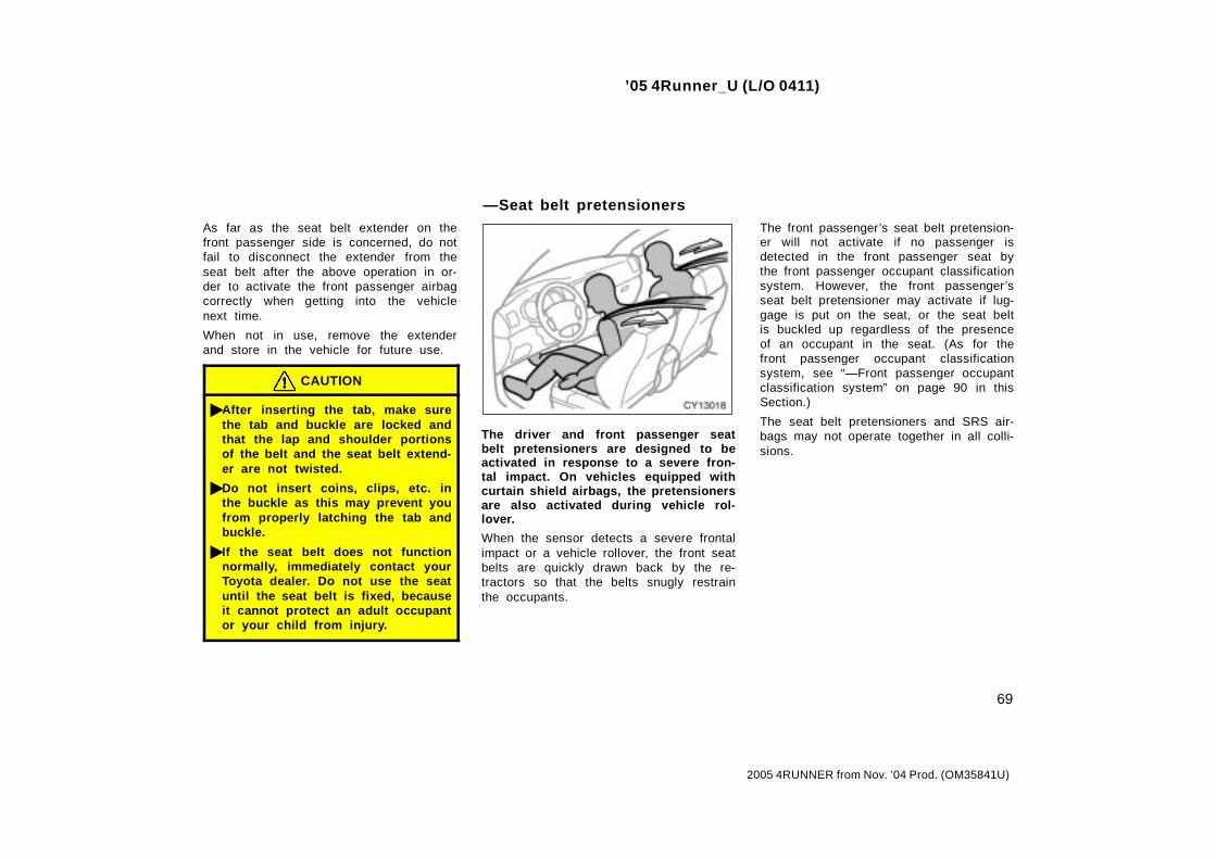
’05 4Runner_U (L/O 0411)
69
2005 4RUNNER from Nov. ’04 Prod. (OM35841U)
As far as the seat belt extender on thefront passenger side is concerned, do notfail to disconnect the extender from theseat belt after the above operation in or-der to activate the front passenger airbagcorrectly when getting into the vehiclenext time.
When not in use, remove the extenderand store in the vehicle for future use.
CAUTION
� After inserting the tab, make surethe tab and buckle are locked andthat the lap and shoulder portionsof the belt and the seat belt extend-er are not twisted.
� Do not insert coins, clips, etc. inthe buckle as this may prevent youfrom properly latching the tab andbuckle.
� If the seat belt does not functionnormally, immediately contact yourToyota dealer. Do not use the seatuntil the seat belt is fixed, becauseit cannot protect an adult occupantor your child from injury.
The driver and front passenger seatbelt pretensioners are designed to beactivated in response to a severe fron-tal impact. On vehicles equipped withcurtain shield airbags, the pretensionersare also activated during vehicle rol-lover.
When the sensor detects a severe frontalimpact or a vehicle rollover, the front seatbelts are quickly drawn back by the re-tractors so that the belts snugly restrainthe occupants.
The front passenger’s seat belt pretension-er will not activate if no passenger isdetected in the front passenger seat bythe front passenger occupant classificationsystem. However, the front passenger’sseat belt pretensioner may activate if lug-gage is put on the seat, or the seat beltis buckled up regardless of the presenceof an occupant in the seat. (As for thefront passenger occupant classificationsystem, see “—Front passenger occupantclassification system” on page 90 in thisSection.)
The seat belt pretensioners and SRS air-bags may not operate together in all colli-sions.
—Seat belt pretensioners

’05 4Runner_U (L/O 0411)
70
2005 4RUNNER from Nov. ’04 Prod. (OM35841U)
Type A
Type B
The seat belt pretensioners will not oper-ate in a vehicle rollover if the “RSCAOFF” indicator light is on. For details, see“Roll sensing of curtain shield airbags offswitch” on page 94 in this Section.
The seat belt pretensioner system con-sists mainly of the following componentsand their locations are shown in the il-lustration.
1. Front airbag sensors
2. SRS warning light
3. Front passenger occupant classificationindicator light
4. Front passenger occupant classificationsystem (ECU and sensors)
5. Seat belt pretensioner assemblies
6. Front passenger’s seat belt buckleswitch
7. Airbag sensor assembly

’05 4Runner_U (L/O 0411)
71
2005 4RUNNER from Nov. ’04 Prod. (OM35841U)
The seat belt pretensioners are controlledby the airbag sensor assembly. The airbagsensor assembly consists of a safing sen-sor and airbag sensor.
When the seat belt pretensioners are acti-vated, an operating noise may be heardand a small amount of non- toxic gas maybe released. This does not indicate thata fire is occurring. This gas is normallyharmless.
Once the seat belt pretensioners havebeen activated, the seat belt retractorsremain locked.
CAUTION
� Do not modify, remove, strike oropen the seat belt pretensioner as-semblies, airbag sensor or sur-rounding area or wiring. Failure tofollow these instructions may pre-vent the seat belt pretensionersfrom activating correctly, cause sud-den operation of the system or dis-able the system, which could resultin death or serious injury. Consultyour Toyota dealer about any repairand modification.
� Do not modify or change the sus-pension system. Such changes maycause the curtain shield airbags toinflate accidentally, which could re-sult in death or serious injury. Con-sult your Toyota dealer about anyrepair and modification.
� Do not use tires or wheels otherthan the manufacture’s recom-mended size. Such a use may causethe curtain shield airbags and seatbelt pretensioners to inflate acci-dentally, which could result in deathor serious injury. For details, see“Checking and replacing tires” onpage 382 in Section 7- 2.
� Do not place luggage heavier thanspecified on the roof luggage carri-er. Such luggage may cause thecurtain shield airbags and seat beltpretensioners to inflate accidentally,which could result in death or seri-ous injury. For details, see “Roofluggage carrier” on page 276 inSection 1- 10.
NOTICE
Do not perform any of the followingchanges without consulting yourToyota dealer. Such changes caninterfere with proper operation of theseat belt pretensioners in somecases.
� Installation of electronic devicessuch as a mobile two- way radio,cassette tape player or compactdisc player
� Repairs on or near the front seatbelt retractor assemblies
� Modification of the front end struc-ture
� Attachment of a grille guard (bullbar, kangaroo bar, etc.), snowplow,winches or any other equipment tothe front end
� Repairs made on or near the frontfenders, front end structure or con-sole

’05 4Runner_U (L/O 0411)
72
2005 4RUNNER from Nov. ’04 Prod. (OM35841U)
This indicator comes on when the igni-tion key is turned to the “ON” position.It goes off after about 6 seconds. Thismeans the seat belt pretensioners areoperating properly.
This warning light system monitors theairbag sensor assembly, front airbag sen-sors, side and curtain shield airbag sen-sors, curtain shield airbag sensors, driv-er’s seat position sensor, driver’s seat beltbuckle switch, front passenger occupantclassification system and indicator light,front passenger’s seat belt buckle switch,seat belt pretensioner assemblies, inflat-ors, warning light, “RSCA OFF” indicatorlight, interconnecting wiring and powersources. (For details, see “Service remind-er indicators and warning buzzers” onpage 145 in Section 1- 6.)
If any of the following conditions occurs,this indicates a malfunction of the airbagsor seat belt pretensioners. Contact yourToyota dealer as soon as possible.
� The light does not come on when theignition key is turned to the “ON” posi-tion or remains on for more than 6seconds or flashes.
� The light comes on or starts flashingwhile driving.
� If any seat belt does not retract or cannot be pulled out due to a malfunctionor activation of the relevant seat beltpretensioner.
� The seat belt pretensioner assembly orsurrounding area has been damaged.
The SRS warning light will come on andfront passenger occupant classification in-dicator light will indicate “OFF” if there isa malfunction in the front passenger occu-pant classification system.

’05 4Runner_U (L/O 0411)
73
2005 4RUNNER from Nov. ’04 Prod. (OM35841U)
In the following cases, contact your Toyotadealer as soon as possible:
� The front of the vehicle (shaded in theillustration) was involved in an accidentthat was not severe enough to causethe seat belt pretensioners to operate.
� Either seat belt pretensioner assemblyor surrounding area is scratched,cracked, or otherwise damaged.
The SRS (Supplemental Restraint Sys-tem) front airbags are designed to pro-vide further protection for the driverand front passenger in addition to theprimary safety protection provided bythe seat belts.
In response to a severe frontal impact,the SRS front airbags work together withthe seat belts to help reduce injury byinflating. The SRS front airbags help re-duce injuries mainly to the driver’s or frontpassenger’s head or chest caused by hit-ting the vehicle interior.
The SRS front passenger airbag will notactivate if there is no passenger sitting inthe front passenger seat. However, thefront passenger airbag may deploy if lug-gage is put in the seat, or the seat beltis buckled up, regardless of the presenceof an occupant in the seat. (As for thefront passenger occupant classificationsystem, see “—Front passenger occupantclassification system” on page 90 in thisSection.)
Always wear your seat belt properly.
SRS airbags——SRS driver airbag and frontpassenger airbag

’05 4Runner_U (L/O 0411)
74
2005 4RUNNER from Nov. ’04 Prod. (OM35841U)
CAUTION
� The SRS front airbag system is de-signed only as a supplement to theprimary protection of the driver andfront passenger seat belt systems.The driver and front passenger canbe killed or seriously injured by theinflating airbags if they do not wearthe available seat belts properly.During sudden braking just beforea collision, an unrestrained driveror front passenger can move for-ward into direct contact with orclose proximity to the airbag whichmay then deploy during the colli-sion. To ensure maximum protectionin an accident, the driver and allpassengers in the vehicle mustwear their seat belts properly. Wear-ing a seat belt properly during anaccident reduces the chances ofdeath or serious injury or beingthrown out of the vehicle. For in-structions and precautions concern-ing the seat belt system, see “Seatbelts” on page 63 in this Section.
� Improperly seated and/or restrainedinfants and children can be killedor seriously injured by the deploy-ing airbags. An infant or child whois too small to use a seat beltshould be properly secured using achild restraint system. Toyotastrongly recommends that all in-fants and children be placed in therear seat of the vehicle and proper-ly restrained. The rear seat is thesafest for infants and children. Forinstructions concerning the installa-tion of a child restraint system, see“Child restraint” on page 95 in thisSection.
The SRS front airbags are designed todeploy in severe (usually frontal) colli-sions where the magnitude and durationof the forward deceleration of the ve-hicle exceeds the designed thresholdlevel.
The SRS front airbags will deploy if theseverity of the impact is above the de-signed threshold level, comparable to anapproximate 25 km/h (15 mph) collisionwhen the vehicle has the impact straightinto a fixed barrier that does not move ordeform.
However, this threshold velocity will beconsiderably higher if the vehicle strikesan object, such as a parked vehicle orsign pole, which can move or deform onimpact, or if the vehicle is involved in anunderride collision (e.g. a collision inwhich the front of the vehicle “underrides”,or goes under, the bed of a truck, etc.).
It is possible that in some collisionswhere the forward deceleration of the ve-hicle is very close to the designed thresh-old level, the SRS front airbags and theseat belt pretensioners may not activatetogether.
Always wear your seat belts properly.

’05 4Runner_U (L/O 0411)
75
2005 4RUNNER from Nov. ’04 Prod. (OM35841U)
Collision from the rear
Collision from the side
Vehicle rollover
The SRS front airbags are generally notdesigned to inflate if the vehicle is in-volved in a side or rear collision, if itrolls over, or if it is involved in a low-speed frontal collision. But, when ever acollision of any type causes sufficientforward deceleration of the vehicle, de-ployment of the SRS front airbags mayoccur.
Hitting a curb, edgeof pavement orhard surface
Falling into orjumping overa deep hole
Landing hard or vehicle falling
The SRS front airbags may also deployif a serious impact occurs to the under-side of your vehicle. Some examplesare shown in the illustration.
The SRS front airbag system consistsmainly of the following components, andtheir locations are shown in the illustra-tion.
1. Front airbag sensors
2. SRS warning light
3. Front passenger occupant classificationindicator light
4. Airbag module for front passenger (airbag and inflator)
5. Front passenger occupant classificationsystem (ECU and sensors)
6. Front passenger’s seat belt buckleswitch
7. Driver’s seat belt buckle switch

’05 4Runner_U (L/O 0411)
76
2005 4RUNNER from Nov. ’04 Prod. (OM35841U)
8. Driver’s seat position sensor
9. Airbag sensor assembly
10. Airbag module for driver (airbag and inflator)
The airbag sensor assembly consists of asafing sensor and airbag sensor.
The front airbag sensors constantly moni-tor the forward deceleration of the vehicle.If an impact results in a forward decelera-tion beyond the designed threshold level,the system triggers the airbag inflators. Atthis time a chemical reaction in the infla-tors very quickly fills the airbags withnon- toxic gas to help restrain the forwardmotion of the occupants. The front airbagsthen quickly deflate, so that there is noobstruction of the driver’s vision should itbe necessary to continue driving.
When the airbags inflate, they produce aloud noise and release some smoke andresidue along with non- toxic gas. Thisdoes not indicate a fire. This smoke mayremain inside the vehicle for some time,and may cause some minor irritation tothe eyes, skin or breathing. Be sure towash off any residue as soon as possibleto prevent any potential skin irritation withsoap and water. If you can safely exitfrom the vehicle, you should do so imme-diately.
Deployment of the airbags happens in afraction of a second, so the airbags mustinflate with considerable force. While thesystem is designed to reduce serious inju-ries, primarily to the head and chest, itmay also cause other, less severe injuriesto the face, chest, arms and hands. Theseare usually in the nature of minor burnsor abrasions and swelling, but the force ofa deploying airbag can cause more seri-ous injuries, especially if an occupant’shands, arms, chest or head is in closeproximity to the airbag module at the timeof deployment. This is why it is importantfor the occupant to: avoid placing anyobject or part of the body between theoccupant and the airbag module; sitstraight and well back into the seat; wearthe available seat belt properly; and sit asfar as possible from the airbag module,while still maintaining control of the ve-hicle.
Parts of the airbag module (steering wheelhub, airbag cover and inflator) may be hotfor several minutes after deployment, sodo not touch! The airbags inflate onlyonce. The windshield may be damaged byabsorbing some of the force of the inflat-ing airbag.
CAUTION
The driver or front passenger who istoo close to the steering wheel ordashboard during airbag deploymentcan be killed or seriously injured.Toyota strongly recommends that:
� The driver sit as far back as pos-sible from the steering wheel whilestill maintaining control of the ve-hicle.
� The front passenger sit as far backas possible from the dashboard.
� All vehicle occupants be properlyrestrained using the available seatbelts.
For instructions and precautions con-cerning the seating position, see“—Front seat precautions” on page42 in this Section.

’05 4Runner_U (L/O 0411)
77
2005 4RUNNER from Nov. ’04 Prod. (OM35841U)
� Do not sit on the edge of the seator lean against the dashboard whenthe vehicle is in use, since thefront passenger airbag could inflatewith considerable speed and force.Anyone who is up against, or veryclose to, an airbag when it inflates,can be killed or seriously injured.Sit up straight and well back in theseat, and always use your seat beltproperly.
� Toyota strongly recommends that allinfants and children be placed inthe rear seat of the vehicle and beproperly restrained.
� Do not hold a child on your lap orin your arms. Use a child restraintsystem in the rear seat. For instruc-tions concerning the installation ofa child restraint system, see “Childrestraint” on page 95 in this Sec-tion.
� Do not put anything or any part ofyour body on or in front of thedashboard or steering wheel padthat houses the front airbag sys-tem. They might restrict inflation orcause death or serious injury asthey are projected rearward by theforce of the deploying airbags. Like-wise, the driver and front passengershould not hold objects in theirarms or on their knees.

’05 4Runner_U (L/O 0411)
78
2005 4RUNNER from Nov. ’04 Prod. (OM35841U)
� Do not modify or remove any wir-ing. Do not modify, remove, strikeor open any components such asthe steering wheel pad, steeringwheel, column cover, dashboardnear the front passenger airbag,front passenger airbag or airbagsensor assembly. Doing so may pre-vent the front airbag system fromactivating correctly, cause suddenactivation of the system or disablethe system, which could result indeath or serious injury.
Failure to follow these instructionscan result in death or serious injury.Consult your Toyota dealer about anyrepair and modification.
If you wish to modify your vehicle fora person with physical disability, con-sult your Toyota dealer. It may dan-gerously interfere with the SRS frontairbags operation.
NOTICE
Do not perform any of the followingchanges without consulting yourToyota dealer. Such changes can in-terfere with proper operation of theSRS front airbag system in somecases.
� Installation of electronic devicessuch as a mobile two- way radio,cassette tape player or compactdisc player
� Modification of the suspension sys-tem
� Modification of the front end struc-ture
� Attachment of a grille guard (bullbar, kangaroo bar, etc.), snowplow,winches or any other equipment tothe front end
� Repairs made on or near the frontfenders, front end structure, con-sole, steering column, steeringwheel or dashboard near the frontpassenger airbag
This indicator comes on when the igni-tion key is turned to the “ON” position.It goes off after about 6 seconds. Thismeans the SRS front airbags are oper-ating properly.

’05 4Runner_U (L/O 0411)
79
2005 4RUNNER from Nov. ’04 Prod. (OM35841U)
This warning light system monitors theairbag sensor assembly, front airbag sen-sors, side and curtain shield airbag sen-sors, curtain shield airbag sensors, driv-er’s seat position sensor, driver’s seat beltbuckle switch, front passenger occupantclassification system and indicator light,front passenger’s seat belt buckle switch,seat belt pretensioner assemblies, inflat-ors, warning light, “RSCA OFF” indicatorlight, interconnecting wiring and powersources. (For details, see “Service remind-er indicators and warning buzzers” onpage 145 in Section 1- 6.)
If any of the following conditions occurs,this indicates a malfunction of the airbagsor seat belt pretensioners. Contact yourToyota dealer as soon as possible.
� The light does not come on when theignition key is turned to the “ON” posi-tion or remains on for more than 6seconds or flashes.
� The light comes on or starts flashingwhile driving.
The SRS warning light will come on andfront passenger occupant classification in-dicator light will indicate “OFF” if there isa malfunction in the front passenger occu-pant classification system.
In the following cases, contact your Toyotadealer as soon as possible:
� The SRS front airbags have been in-flated.
� The front of the vehicle (shaded in theillustration) was involved in an accidentthat was not severe enough to causethe SRS front airbags to inflate.
� The pad section of the steering wheelor dashboard (shaded in the illustra-tion) is scratched, cracked, or other-wise damaged.
NOTICE
Do not disconnect the battery cablesbefore contacting your Toyota dealer.

’05 4Runner_U (L/O 0411)
80
2005 4RUNNER from Nov. ’04 Prod. (OM35841U)
The SRS (Supplemental Restraint Sys-tem) side airbags and curtain shield air-bags are designed to provide furtherprotection for the driver, front passen-ger and rear seat passengers ∗1/secondseat passengers ∗2 in addition to the pri-mary safety protection provided by theseat belts.∗1: Without third seats∗2: With third seats
In response to a severe side impact, theSRS side airbag and curtain shield airbagsin the impacted side work with the seatbelts to help reduce injury by inflating.The SRS side airbags help reduce injuriesmainly to the driver’s or front passenger’schest. The SRS curtain shield airbagshelp reduce injuries mainly to the driver’s,front passenger’s or rear/second passen-ger’s head and help prevent them frombeing thrown out of the vehicle.
The SRS side airbag on the passengerseat will not activate if there is no pas-senger sitting in the front passenger seat.However, the side airbag on the passen-ger seat may deploy if luggage is put inthe seat, or the seat belt is buckled upregardless of the presence of the occu-pant in the seat. (As for the front passen-ger occupant classification system, see“—Front passenger occupant classificationsystem” on page 90 in this Section.)
The SRS curtain shield airbag on the pas-senger side are activated even with nopassenger in the front seat or rear/secondoutside seat.
Roll sensing function:In response to a vehicle rollover, the cur-tain shield airbags on both sides workwith the seat belts to help reduce injuryby inflating. The curtain shield airbagshelp reduce injuries mainly to the driver’s,front passenger’s or rear/second passen-ger’s head and help prevent them frombeing thrown out of the vehicle. (Thisfunction can be turned off if inflation isnot desired. See “Roll sensing of curtainshield airbags off switch” on page 94 inthis Section.)
The SRS curtain shield airbags may acti-vate even when the side airbags are notactivated.
Always wear your seat belt properly.
—SRS side airbags andcurtain shield airbags

’05 4Runner_U (L/O 0411)
81
2005 4RUNNER from Nov. ’04 Prod. (OM35841U)
CAUTION
� The SRS side airbag and curtainshield airbag system is designedonly as a supplement to theprimary protection of the driver,front passenger and rear /secondpassenger seat belt systems. Toensure maximum protection in anaccident, the driver and all passen-gers in the vehicle must wear theirseat belts properly. Wearing a seatbelt properly during an accidentreduces the chances of death orserious injury or being thrown outof the vehicle. For instructions andprecautions concerning the seatbelt system, see “Seat belts” onpage 63 in this Section.
� Do not allow anyone to lean his/herhead or any part of his/her bodyagainst the door or the area of theseat, front p illar, rear pillar or roofside rail from which the SRS sideairbag and curtain shield airbagdeploy even if he/she is a childseated in the child restraint system.It is dangerous if the SRS side air-bag and curtain shield airbag in-flate, and the impact of the deploy-ing airbag could cause death or se-rious injury to the occupant.
� Improperly seated and/or restrainedinfants and children can be killedor seriously injured by the deploy-ing airbags. An infant or child whois too small to use a seat beltshould be properly secured using achild restraint system. Toyotastrongly recommends that all in-fants and children be placed in therear seats of the vehicle and prop-erly restrained. The rear seats arethe safest for infants and children.For instructions concerning theinstallation of a child restraint sys-tem, see “Child restraint” on page95 in this Section.

’05 4Runner_U (L/O 0411)
82
2005 4RUNNER from Nov. ’04 Prod. (OM35841U)
The SRS side airbags may not activateif the vehicle is subjected to a collisionfrom the side at certain angles, or acollision to the side of the vehicle bodyother than the passenger compartmentas shown in the illustration.
The SRS side airbags are designed toinflate when the passenger compartmentarea suffers a severe impact from theside.
Always wear your seat belts properly.
Collision from the rear
Vehicle rollover
Collision from the front
The SRS side airbags are not generallydesigned to inflate if the vehicle is in-volved in a front or rear collision, if itrolls over, or if it is involved in a low-speed side collision.
The curtain shield airbags may not acti-vate if the vehicle is subjected to acollision from the side at certainangles, or a collision to the side of thevehicle body other than the passengercompartment as shown in the illustra-tion.
The curtain shield airbags are designed toinflate when the passenger compartmentarea suffers a severe impact from theside or vehicle rollover.
Always wear your seat belts properly.

’05 4Runner_U (L/O 0411)
83
2005 4RUNNER from Nov. ’04 Prod. (OM35841U)
The angle ofvehicle tip- upis marginal
Skidding vehiclehitting a curbstone
The curtain shield airbags may inflateif the angle of vehicle tip- up is margin-al or if the skidding vehicle’s tires hita curb stone laterally as shown in theillustration.
Collision fromthe front Collision from
the rear
Pitch end over end
The curtain shield airbags are not gen-erally designed to inflate if the vehicleis involved in a front or rear collision,if it pitches end over end, or if it isinvolved in a low- speed side collision.
Hitting a curb, edgeof pavement orhard surface
Falling into orjumping overa deep hole
Landing hard or vehicle falling
The SRS side and curtain shield airbagsmay deploy if a serious impact occursto the underside of your vehicle. Someexamples are shown in the illustration.

’05 4Runner_U (L/O 0411)
84
2005 4RUNNER from Nov. ’04 Prod. (OM35841U)
The SRS side airbag and curtain shieldairbag system consists mainly of the fol-lowing components, and their locations areshown in the illustration.
1. SRS warning light
2. Front passenger occupant classificationindicator light
3. Curtain shield airbag modules(airbag and inflator)
4. Front passenger occupant classificationsystem (ECU and sensors)
5. Side airbag modules (airbag and inflator)
6. Curtain shield airbag sensors
7. Side and curtain shield airbag sensors
8. Front passenger’s seat belt buckleswitch
9. Airbag sensor assembly
The SRS side airbag and curtain shieldairbag system is controlled by the airbagsensor assembly. The airbag sensor as-sembly consists of a safing sensor andairbag sensor.
In a severe side impact, the side andcurtain shield airbag sensor and/or thecurtain shield airbag sensor trigger(s) theside airbag inflators and/or the curtainshield airbag inflators. At this time achemical reaction in the inflators quicklyfills the airbags with non- toxic gas to helprestrain the lateral motion of the occu-pants.
In a vehicle rollover, the airbag sensorassembly triggers the curtain shield airbaginflator. At this time, a chemical reactionin the inflators quickly fills the airbagswith non- toxic gas to help restrain thelateral motion of the occupants.
When the airbags inflate, they produce afairly loud noise and release some smokeand residue along with non- toxic gas. Thisdoes not indicate a fire. This smoke mayremain inside the vehicle for some time,and may cause some minor irritation tothe eyes, skin or breathing. Be sure towash off any residue as soon as possibleto prevent any potential skin irritation withsoap and water. If you can safely exitfrom the vehicle, you should do so imme-diately.
Deployment of the airbags happens in afraction of a second, so the airbags mustinflate with considerable force. While thesystem is designed to reduce serious inju-ries, it may also cause minor burns orabrasions and swelling.
Front seats as well as parts of the frontand rear pillars, front, center and reargarnish and roof interior may be hot forseveral minutes, but the airbags them-selves will not be hot. The airbags aredesigned to inflate only once.

’05 4Runner_U (L/O 0411)
85
2005 4RUNNER from Nov. ’04 Prod. (OM35841U)
CAUTION
SRS side airbags and curtain shieldairbags inflate with considerableforce. To reduce the possibility ofdeath or serious injury when they in-flate, the driver, front passenger andrear/second passengers must:
� Wear their seat belts properly.
� Remain properly seated with theirbacks upright and against the seatsat all times.
Improper sitting and wearing of theseat belts may not retain you insidethe vehicle.
� Do not allow anyone to lean againstthe door when the vehicle is in use,since the side airbag and curtainshield airbag could inflate with con-siderable speed and force. Other-wise, he/she may be killed or seri-ously injured. Special care shouldbe taken especially when you havea small child in the vehicle.
� Sit up straight and well back in theseat, distributing your weight evenlyin the seat. Do not apply excessiveweight to the outer side of theseats with a side airbag, and to thefront pillar, rear pillar and roof siderail with a curtain shield airbag.
Type A
Type B

’05 4Runner_U (L/O 0411)
86
2005 4RUNNER from Nov. ’04 Prod. (OM35841U)
� Make sure the “RSCA OFF” indica-tor light is off. The curtain shieldairbags will not inflate in a vehiclerollover if this indicator light is onand you may be killed or seriouslyinjured. For details, see “Roll sens-ing of curtain shield airbags offswitch” on page 94 in this Section.
� Do not allow anyone to get his/herhead closer to the area where theside airbag and curtain shield air-bag inflate, since these airbagscould inflate with considerablespeed and force. Otherwise, he/shemay be killed or seriously injured.Special care should be taken espe-cially when you have a small childin the vehicle.
� Do not allow anyone to kneel onthe passenger seat, facing the pas-senger’s side door, since the sideairbag and curtain shield airbagcould inflate with considerablespeed and force. Otherwise, he/shemay be killed or seriously injured.Special care should be taken espe-cially when you have a small childin the vehicle.

’05 4Runner_U (L/O 0411)
87
2005 4RUNNER from Nov. ’04 Prod. (OM35841U)
� Do not allow anyone to get his/herhead or hands out of windowssince the curtain shield airbagscould inflate with considerablespeed and force. Otherwise, he/shemay be killed or seriously injured.Special care should be taken espe-cially when you have a small childin the vehicle.
� Do not attach a cup holder or anyother device or object on or aroundthe door. When the side airbag in-flates, the cup holder or any otherdevice or object will be thrown withgreat force or the side airbag maynot activate correctly, resulting indeath or serious injury. Likewise,the driver and front passengershould not hold objects in theirarms or on their knees.
� Do not attach a microphone or anyother device or object near the areawhere the curtain shield airbags ac-tivate such as on the windshieldglass, side door glass, front, centerand roof side garnish, roof interioror assist grips. When the curtainshield airbags inflate, the micro-phone or other device or object willbe hurled with great force or thecurtain shield airbags may not acti-vate correctly, which could result indeath or serious injury.

’05 4Runner_U (L/O 0411)
88
2005 4RUNNER from Nov. ’04 Prod. (OM35841U)
� Do not hook a hanger, heavy orsharp pointed objects on the coathook. If the curtain shield airbaginflates, those items will be thrownaway with great force or the curtainshield airbag may not activate cor-rectly, resulting in death or seriousinjury. When you hang clothes,hang them on the coat hook direct-ly.
� Do not use seat accessories whichcover the parts where the side air-bags inflate. Such accessories mayprevent the side airbags from acti-vating correctly, causing death orserious injury.
� Do not modify or replace the seatsor upholstery of the seats with sideairbags. Such changes may preventthe side airbag system from activat-ing correctly, disable the system orcause the side airbags to inflate ac-cidentally, resulting in death or seri-ous injury.
� Do not disassemble or repair thefront pillars and roof side rails con-taining the curtain shield airbags.Such changes may disable the sys-tem or cause the curtain shield air-bags to inflate accidentally, result-ing in death or serious injury.
� Do not modify or change the sus-pension system. Such changes maycause the curtain shield airbags toinflate accidentally, which could re-sult in death or serious injury.
� Do not use tires or wheels otherthan the manufacturer’s recom-mended size. Such a use may causethe curtain shield airbags to inflateaccidentally, which could result indeath or serious injury. For details,see “Checking and replacing tires”on page 382 in Section 7- 2.
� Do not place luggage heavier thanspecified on the roof luggage carri-er. Such luggage may cause thecurtain shield airbags to inflate ac-cidentally, which could result indeath or serious injury. For details,see “Roof luggage carrier” on page276 in Section 1- 10.
Failure to follow these instructionscan result in death or serious injury.Consult your Toyota dealer about anyrepair and modification.
If you wish to modify your vehicle fora person with physical disability, con-sult your Toyota dealer. It may dan-gerously interfere with the SRS sideairbags and curtain shield airbags op-eration.
NOTICE
Do not perform any of the followingchanges without consulting yourToyota dealer. Such changes caninterfere with proper operation of theSRS side airbag and curtain shieldairbag system in some cases.
� Installation of electronic devicessuch as a mobile two- way radio,cassette tape player or compactdisc player
� Modification of the side structure ofthe passenger compartment
� Repairs made on or near the con-sole or front seat

’05 4Runner_U (L/O 0411)
89
2005 4RUNNER from Nov. ’04 Prod. (OM35841U)
This indicator comes on when the igni-tion key is turned to the “ON” position.It goes off after about 6 seconds. Thismeans the SRS side airbags and curtainshield airbags are operating properly.
This warning light system monitors theairbag sensor assembly, front airbag sen-sors, side and curtain shield airbag sen-sors, curtain shield airbag sensors, driv-er’s seat position sensor, driver’s seat beltbuckle switch, front passenger occupantclassification system and indicator light,front passenger’s seat belt buckle switch,seat belt pretensioner assemblies, inflat-ors, warning light, “RSCA OFF” indicatorlight, interconnecting wiring and powersources. (For details, see “Service remind-er indicators and warning buzzers” onpage 145 in Section 1- 6.)
If any of the following conditions occurs,this indicates a malfunction of the airbagsor seat belt pretensioners. Contact yourToyota dealer as soon as possible.
� The light does not come on when theignition key is turned to the “ON” posi-tion or remains on for more than 6seconds or flashes.
� The light comes on or starts flashingwhile driving.
The SRS warning light will come on andfront passenger occupant classification in-dicator light will indicate “OFF” if there isa malfunction in the front passenger occu-pant classification system.

’05 4Runner_U (L/O 0411)
90
2005 4RUNNER from Nov. ’04 Prod. (OM35841U)
In the following cases, contact your Toyotadealer as soon as possible:
� Any of the SRS side airbags and cur-tain shield airbags have been inflated.
� The portion of the doors (shaded in theillustration) was involved in an accidentthat was not severe enough to causethe SRS side airbags and curtainshield airbags to inflate.
� The surface of the seats with the sideairbag (shaded in the illustration) isscratched, cracked, or otherwise dam-aged.
� The portion of the front, center andrear garnish, and roof interior contain-ing the curtain shield airbags inside(shaded in the illustration) is scratched,cracked, or otherwise damaged.
NOTICE
Do not disconnect the battery cablesbefore contacting your Toyota dealer.
Your vehicle is equipped with a frontpassenger occupant classification sys-tem. This system detects the conditions1—4 in the table on page 92 and basedon these conditions activates or deacti-vates the airbags and the front passen-ger’s seat belt pretensioner. The systemmonitors the weight and load on thefront passenger seat, and the seat beltbuckle switch to determine conditions1—4.
In order for the system to detect theconditions correctly, do not do any ofthe following:
� Apply a heavy load to the front pas-senger seat.
� Attach a commercial seatback table,etc. to the front passenger seatback.
� Put weight on the front passenger seatby putting your hands or feet on theseatback from the rear passenger seat.
The front passenger occupant classifi-cation indicator light indicates the ac-tuation of the front passenger airbag,side airbag on the front passenger seatand front passenger’s seat belt preten-sioner.
The indicator light will indicate “OFF”when the ignition switch is in the “ON”position with the condition 2 in the tableshown below.
—Front passenger occupantclassification system

’05 4Runner_U (L/O 0411)
91
2005 4RUNNER from Nov. ’04 Prod. (OM35841U)
If the front passenger occupant classifica-tion system determines that a person ofadult size sits in the front passenger seatbut the “OFF” indicator is illuminated, oneof the following is likely to have occurred:
� A rear passenger lifts the front passen-ger seat cushion with their legs.
� Objects are placed under the front pas-senger seat.
� The front passenger seatback is incontact with the rear/second seat.
To ensure the system correctly detects anadult sitting in the front passenger seat,make sure the above do not occur.
Make sure that the “ON” indicator is illu-minated when an adult is seated in thefront passenger seat. If the “OFF” indica-tor is illuminated, ask the passenger to situp straight, well back in the seat, andwith the seat belt worn correctly. If the“OFF” indicator still remains illuminated,either ask the passenger to move to therear seat, or if that is not possible, movethe front passenger seat fully rearward.
The front passenger occupant classifi-cation indicator light will indicate “ON”and “OFF” when the ignition key isturned to the “ON” position. Afterabout four seconds, it will go off. Afterthat, the front passenger occupant clas-sification system operates and judgeswhether to indicate “ON” or “OFF”.
The SRS warning light will come onand front passenger occupant classifi-cation indicator light will indicate“OFF” if there is a malfunction in thefront passenger occupant classificationsystem.

’05 4Runner_U (L/O 0411)
92
2005 4RUNNER from Nov. ’04 Prod. (OM35841U)
Condition and operation in the front passenger occupant classification system
Indicator/warning light Devices
Condition detected bythe front passenger
occupant classificationsystem
Frontpassengeroccupant
classificationindicator light
SRS warninglight
Frontpassenger’s
seat beltreminder light
Frontpassenger
airbag
Side airbagon the frontpassenger
seat
Curtain shieldairbag in the
frontpassenger
side
Frontpassenger’s
seat beltpretensioner
1. Adult∗1 “ON” Off Flashing∗4 Activated
2. Child∗2 or childrestraint system∗3 “OFF” Off Flashing∗4 Deactivated Activated
3. Unoccupied Notilluminated
Off Off DeactivatedActivated
Deactivated
4. There is amalfunction in thesystem
“OFF” On Off Deactivated Activated
∗1: The system judges a person of adult size as an adult. When a smaller adult sits in the front passenger seat, the system mayrecognize him/her as a child depending on his/her physique and posture.
∗2: When a larger child who has outgrown a child restraint system sits in the front passenger seat, the system may recognize him/heras an adult depending on his/her physique or posture.
∗3: Never install a rear- facing child restraint system on the front passenger seat. A forward- facing child restraint system should only beinstalled on the front passenger seat when it is unavoidable. (See “Child restraint” on page 95 in this Section as for installing thechild restraint system.)
∗4: In the event the front passenger does not wear a seat belt.

’05 4Runner_U (L/O 0411)
93
2005 4RUNNER from Nov. ’04 Prod. (OM35841U)
CAUTION
To avoid potential death or seriousinjury when the front passenger occu-pant classification system does notdetect the conditions correctly, ob-serve the following.
� Make sure the front passenger oc-cupant classification indicator lightindicates “ON” when using the seatbelt extender for the front passen-ger seat. If the indicator light indi-cates “OFF”, disconnect the extend-er tongue from the seat belt buckle,then reconnect the seat belt. Recon-nect the seat belt extender aftermaking sure the indicator light indi-cates “ON”. If you use the seat beltextender while the indicator lightindicates “OFF”, the front passen-ger airbag and side airbag on thefront passenger side may not acti-vate correctly, which could causedeath or serious injury in the eventof collision.
� Do not recline the front passengerseatback so far that it touches asecond seat. This may cause the“OFF” indicator to be illuminated,which indicates that the passen-ger’s airbags will not deploy in theevent of a severe accident. If theseatback touches the rear/secondseat, return the seatback to a posi-tion where it does not touches therear/second seat.
Keep the front passenger seatbackas upright as possible when the ve-hicle is moving. Reclining the seat-back excessively may lessen the ef-fectiveness of the seat belt system.
� If an adult sits in the front passen-ger seat, the occupant classificationindicator light should indicate “ON”.If the “OFF” indicator is illumina-ted, ask the passenger to sit upstraight, well back in the seat, feeton the floor, and with the seat beltworn correctly. If the “OFF” indica-tor still remains illuminated, eitherask the passenger to move to therear/second seat, or if that is notpossible, move the front passengerseat fully rearward.
� Wear the seat belt properly.
� Make sure the front passenger’sseat belt tab has not been left in-serted into the buckle before some-one sits in the front passengerseat.
� Do not apply a heavy load to thefront passenger seat.
� Do not put weight on the front pas-senger seat by putting your handsor feet on the front passenger seatseatback from the rear/second pas-senger seat.
� Do not let a rear/second passengerlift the front passenger seat withtheir feet or press on the seatbackwith their legs.
� Do not put objects under the frontpassenger seat.
� Child restraint systems installed onthe rear/second seat should notcontact the front seatbacks.

’05 4Runner_U (L/O 0411)
94
2005 4RUNNER from Nov. ’04 Prod. (OM35841U)
� When it is unavoidable to install theforward- facing child restraint sys-tem on the front passenger seat,install the child restraint system onthe front passenger seat in theproper order. (As for the installationorder, see “—Installation with seatbelt” on page 98 in this Section.)
� Do not remove the front seats.
� Do not kick the front passengerseat or subject it to severe impact.Otherwise, the SRS warning lightmay come on to indicate a malfunc-tion of the detection system. In thiscase, contact your Toyota dealer im-mediately.
The front passenger occupant classifica-tion indicator light may indicate “ON” (thefront passenger airbag and side airbag onthe front passenger seat may deploy)even if observing the above cautions,when a child sits in, or a forward- facingchild restraint system is installed on thefront passenger seat. Refer to all the cau-tions in “SRS airbags” on page 73 and“Child restraint” on page 95 in this Sec-tion.
The roll sensing of curtain shield air-bags off switch (“RSCA OFF” switch)can turn off the curtain shield airbagsand seat belt pretensioners in a vehiclerollover. This switch should only beused if inflation is not desired (such asextreme off- road driving).
When you push the “RSCA OFF” switchfor a few seconds with the ignition switchon, the “RSCA OFF” indicator light comeson and the roll sensing function is turnedoff. When you push the switch again, theindicator light goes off and the roll sens-ing function is turned on. (For detailsabout the roll sensing function, see“—SRS side airbags and curtain shieldairbags” on page 80 in this Section.)
In a severe side impact, the curtain shieldairbags on impacted side will inflate evenif the roll sensing function is turned off.(For details about the curtain shield air-bags, see “—SRS side airbags and curtainshield airbags” on page 80 in this Sec-tion.)
In a severe frontal impact, the seat beltpretensioners will work even if the rollsensing function is turned off. (For detailsabout the seat belt pretensioners, see“—Seat belt pretensioners” on page 69 inthis Section.)
If the ignition switch is turned to “ACC” or“LOCK” with the roll sensing function offand then the ignition switch is turned backto “ON”, the roll sensing function will turnback on automatically.
Roll sensing of curtain shieldairbags off switch

’05 4Runner_U (L/O 0411)
95
2005 4RUNNER from Nov. ’04 Prod. (OM35841U)
CAUTION
� Before normal driving, make surethe “RSCA OFF” indicator light isoff.
� When the roll sensing function isturned off (and the “RSCA OFF”indicator light is on), the curtainshield airbags and seat belt preten-sioners will not work in a vehiclerollover. Turning off the curtainshield airbags and seat belt preten-sioners reduces occupant protectionwhich your vehicle safety systemscan provide in accidents and in-crease the likelihood of death orserious injuries.
Toyota strongly urges the use of ap-propriate child restraint systems forchildren.
The laws of all 50 states in the U.S.A.and Canada now require the use of achild restraint system.
Your vehicle conforms to SAE J1819.
If a child is too large for a child restraintsystem, the child should sit in the rearseat and must be restrained using thevehicle’s seat belt. See “Seat belts” onpage 63 in this Section for details.
CAUTION
� For effective protection in automo-bile accidents and sudden stops, achild must be properly restrained,using a seat belt or child restraintsystem depending on the age andsize of the child. Holding a child inyour arms is not a substitute for achild restraint system. In an acci-dent, the child can be crushedagainst the windshield, or betweenyou and the vehicle’s interior.
� Toyota strongly urges use of aproper child restraint system whichconforms to the size of the child,and is put on the rear seat. Accord-ing to accident statistics, the childis safer when properly restrained inthe rear seat than in the front seat.
� Never install a rear- facing child re-straint system on the front passen-ger seat even if the front passengeroccupant classification indicatorlight indicates “OFF”. In the eventof an accident, the impact of therapid inflation of the front passen-ger airbag could cause death or se-rious injury to the child if the rear-facing child restraint system isinstalled on the front passengerseat.
Child restraint——Child restraint precautions

’05 4Runner_U (L/O 0411)
96
2005 4RUNNER from Nov. ’04 Prod. (OM35841U)
� A forward- facing child restraint sys-tem should be allowed to beinstalled on the front passengerseat only when it is unavoidable.Always move the seat as far backas possible even if the front pas-senger occupant classification indi-cator light indicates “OFF”, becausethe front passenger airbag could in-flate with considerable speed andforce. Otherwise, the child may bekilled or seriously injured.
� On vehicles with side airbags andcurtain shield airbags, do not allowthe child to lean his/her head orany part of his/her body against thedoor or the area of the seat, frontor rear pillar or roof side rail fromwhich the side airbags or curtainshield airbags deploy even if thechild is seated in the child restraintsystem. It is dangerous if the sideairbag and curtain shield airbag in-flate, and the impact could causedeath or serious injury to the child.
� Do not use the seat belt extenderwhen installing a child restraintsystem on the front or rear passen-ger seat. If installing a child re-straint system with the seat beltextender connected to the seat belt,the seat belt will not securely holdthe child restraint system, whichcould cause death or serious injuryto the child or other passengers inthe event of collision.
� Make sure you have complied withall installation instructions providedby the child restraint manufacturerand that the system is properly se-cured. If it is not secured properly,it may cause death or serious injuryto the child in the event of a sud-den stop or accident.
A child restraint system for a smallchild or baby must itself be properlyrestrained on the seat with the lap por-tion of the lap/shoulder belt. You mustcarefully consult the manufacturer’sinstructions which accompany the childrestraint system.
To provide proper restraint, use a childrestraint system following the manufactur-er’s instructions about the appropriate ageand size of the child for the child restraintsystem.
Install the child restraint system correctlyfollowing the instructions provided by itsmanufacturer. General directions are alsoprovided under the following illustrations.
The child restraint system should beinstalled on the rear seat. According toaccident statistics, the child is safer whenproperly restrained in the rear seat thanin the front seat.
When not using the child restraint system,keep it secured with the seat belt or placeit somewhere other than the passengercompartment. This will prevent it from in-juring passengers in the event of a sud-den stop or accident.
—Child restraint system

’05 4Runner_U (L/O 0411)
97
2005 4RUNNER from Nov. ’04 Prod. (OM35841U)
Child restraint systems are classified intothe following 3 types depending on thechild’s age and size.
(A) Infant seat(B) Convertible seat(C) Booster seat
Install the child restraint system followingthe instructions provided by its manufac-turer.
Your vehicle has anchor brackets for se-curing the top strap of a child restraintsystem.
For instructions about how to use the an-chor bracket, see “—Using a top strap” onpage 108 in this Section.
The child restraint lower anchorages ap-proved for your vehicle may also be used.See “—Installation with child restraint low-er anchorages” on page 112 in this Sec-tion.
(A) Infant seat
(B) Convertible seat
(C) Booster seat
—Types of child restraintsystem

’05 4Runner_U (L/O 0411)
98
2005 4RUNNER from Nov. ’04 Prod. (OM35841U)
(A) INFANT SEAT INSTALLATION
An infant seat must be used in rear-facing position only.
CAUTION
� Never install a rear- facing child re-straint system on the front passen-ger seat even if the front passengeroccupant classification indicatorlight indicates “OFF”. In the eventof an accident, the impact of therapid inflation of the front passen-ger airbag could cause death or se-rious injury to the child if the rear-facing child restraint system isinstalled on the front passengerseat.
� Do not install a child restraint sys-tem on the second (or third) seat ifit interferes with the lock mecha-nism of the front (or second) seats.Otherwise, the child or front (orsecond) seat occupant(s) may bekilled or seriously injured in caseof sudden braking or a co llision.
� If the driver’s seat position doesnot allow sufficient space for safeinstallation, install the child re-straint system on the rear rightseat.
—Installation with seat belt

’05 4Runner_U (L/O 0411)
99
2005 4RUNNER from Nov. ’04 Prod. (OM35841U)
1. Run the lap and shoulder belt throughor around the infant seat following theinstructions provided by its manufactur-er and insert the tab into the buckletaking care not to twist the belt. Keepthe lap portion of the belt tight.
CAUTION
� After inserting the tab, make surethe tab and buckle are locked andthat the lap and shoulder portionsof the belt are not twisted.
� Do not insert coins, clips, etc. inthe buckle as this may prevent yourchild from properly latching the taband buckle.
� If the seat belt does not functionnormally, it cannot protect yourchild from death or serious injury.Contact your Toyota dealer immedi-ately. Do not install the childrestraint system on the seat untilthe seat belt is fixed.
2. Fully extend the shoulder belt to put itin the lock mode. When the belt isthen retracted even slightly, it cannotbe extended.
To hold the infant seat securely, makesure the belt is in the lock mode beforeletting the belt retract.

’05 4Runner_U (L/O 0411)
100
2005 4RUNNER from Nov. ’04 Prod. (OM35841U)
3. While pressing the infant seat firmlyagainst the seat cushion and seatback,let the shoulder belt retract as far asit will go to hold the infant seat secure-ly.
CAUTION
Push and pull the child restraint sys-tem in different directions to be sureit is secure. Follow all the installationinstructions provided by its manufac-turer.
4. To remove the infant seat, press thebuckle release button and allow thebelt to retract completely. The belt willmove freely again and be ready towork for an adult or older child passen-ger.

’05 4Runner_U (L/O 0411)
101
2005 4RUNNER from Nov. ’04 Prod. (OM35841U)
(B) CONVERTIBLE SEAT INSTALLATION
A convertible seat must be used in for-ward- facing or rear- facing position de-pending on the age and size of thechild. When installing, follow themanufacturer’s instructions about theapplicable age and size of the child aswell as directions for installing thechild restraint system.
Install the child restraint system on thefront passenger seat only when it is un-avoidable. Your vehicle is equipped with afront passenger occupant classificationsystem. In order to activate the occupantclassification system correctly, install theforward- facing child restraint system onthe front passenger seat in the followingorder:
1. Turn the ignition key to the “ON” posi-tion.
2. Move the front passenger seat to therearward position.
3. Put the child restraint system on thefront passenger seat without puttingyour weight on the front passengerseat.
4. Insert the seat belt tab into the seatbelt buckle.
5. Fully extend the shoulder belt to put itin the lock mode. When the belt isthen retracted even slightly, it cannotbe extended. To hold the seat securely,make sure the belt is in the lock modebefore letting the belt retract.
6. While pressing the convertible seatfirmly against the seat cushion andseatback, let the shoulder belt retractas far as it will go to hold the convert-ible seat securely.
CAUTION
Push and pull the child restraint sys-tem in different directions to be sureit is secure. Follow all the installationinstructions provided by its manufac-turer.
7. Put a child on the child restraint sys-tem and secure the child, complyingwith the instructions provided by thechild restraint system manufacturer.

’05 4Runner_U (L/O 0411)
102
2005 4RUNNER from Nov. ’04 Prod. (OM35841U)
The occupant classification indicator lightshould indicate “OFF” when the ignitionkey is “ON” and the child is in the childrestraint system after following these pro-cedures. The “OFF” indicator indicates theSRS front passenger airbag and side air-bag on the passenger side will not deploy.If the indicator light indicates “ON”, re-move the child restraint system and rein-stall it with the ignition key in the “ACC”or “LOCK” position. If the indicator lightstill indicates “ON” when the ignition keyis turned to the “ON” position, then theSRS front passenger airbag and side air-bag on the passenger side may deploy inan accident. Do not drive the vehicle inthis condition. Remove the child restraintsystem and contact your Toyota dealer.
CAUTION
� Never install a rear- facing child re-straint system on the front passen-ger seat. A forward- facing child re-straint system should only beinstalled on the front passengerseat when unavoidable. If you mustinstall the child restraint system onthe front passenger seat, put theseat in its most rearward position,and install the forward- facing childrestraint system in the proper or-der. Otherwise, the front passengeroccupant classification system cannot detect the presence of the childrestraint system and the front pas-senger airbag and side airbag onthe front passenger seat coulddeploy.
CAUTION
� Never install a rear- facing child re-straint system on the front passen-ger seat even if the front passengeroccupant classification indicatorlight indicates “OFF”. In the eventof an accident, the impact of therapid inflation of the front passen-ger airbag could cause death or se-rious injury to the child if the rear-facing child restraint system isinstalled on the front passengerseat.

’05 4Runner_U (L/O 0411)
103
2005 4RUNNER from Nov. ’04 Prod. (OM35841U)
Move seatfully back
� A forward- facing child restraint sys-tem should be allowed to beinstalled on the front passengerseat only when it is unavoidable.Always move the seat as far backas possible even if the front pas-senger occupant classification indi-cator light indicates “OFF”, becausethe front passenger airbag could in-flate with considerable speed andforce. Otherwise, the child may bekilled or seriously injured.
� On vehicles with side airbags andcurtain shield airbags, do not allowthe child to lean his/her head orany part of his/her body against thedoor or the area of the seat, frontor rear pillar or roof side rail fromwhich the side airbags or curtainshield airbags deploy even if thechild is seated in the child restraintsystem. It is dangerous if the sideairbag and curtain shield airbag in-flate, and the impact could causedeath or serious injury to the child.
� Do not install a child restraint sys-tem on the second (or third) seat ifit interferes with the lock mecha-nism of the front (or second) seats.Otherwise, the child or front (orsecond) seat occupant(s) may bekilled or seriously injured in caseof sudden braking or a co llision.
� If the driver’s seat position doesnot allow sufficient space for safeinstallation, install the child re-straint system on the rear rightseat.

’05 4Runner_U (L/O 0411)
104
2005 4RUNNER from Nov. ’04 Prod. (OM35841U)
1. Run the lap and shoulder belt throughor around the convertible seat followingthe instructions provided by itsmanufacturer and insert the tab intothe buckle taking care not to twist thebelt. Keep the lap portion of the belttight.
CAUTION
� After inserting the tab, make surethe tab and buckle are locked andthat the lap and shoulder portionsof the belt are not twisted.
� Do not insert coins, clips, etc. inthe buckle as this may prevent yourchild from properly latching the taband buckle.
� If the seat belt does not functionnormally, it cannot protect yourchild from death or serious injury.Contact your Toyota dealer immedi-ately. Do not install the childrestraint system on the seat untilthe seat belt is fixed.
2. Fully extend the shoulder belt to put itin the lock mode. When the belt isthen retracted even slightly, it cannotbe extended.
To hold the convertible seat securely,make sure the belt is in the lock modebefore letting the belt retract.

’05 4Runner_U (L/O 0411)
105
2005 4RUNNER from Nov. ’04 Prod. (OM35841U)
3. While pressing the convertible seatfirmly against the seat cushion andseatback, let the shoulder belt retractas far as it will go to hold the convert-ible seat securely.
CAUTION
Push and pull the child restraint sys-tem in different directions to be sureit is secure. Follow all the installationinstructions provided by its manufac-turer.
4. To remove the convertible seat, pressthe buckle release button and allow thebelt to retract completely. The belt willmove freely again and be ready towork for an adult or older child passen-ger.

’05 4Runner_U (L/O 0411)
106
2005 4RUNNER from Nov. ’04 Prod. (OM35841U)
(C) BOOSTER SEAT INSTALLATION
A booster seat must be used in for-ward- facing position only.
Move seatfully back
CAUTION
� A forward- facing child restraint sys-tem should be allowed to beinstalled on the front passengerseat only when it is unavoidable.Always move the seat as far backas possible even if the front pas-senger occupant classification indi-cator light indicates “OFF”, becausethe front passenger airbag could in-flate with considerable speed andforce. Otherwise, the child may bekilled or seriously injured.
� On vehicles with side airbags andcurtain shield airbags, do not allowthe child to lean his/her head orany part of his/her body against thedoor or the area of the seat, frontor rear pillar or roof side rail fromwhich the side airbags or curtainshield airbags deploy even if thechild is seated in the child restraintsystem. It is dangerous if the sideairbag and curtain shield airbag in-flate, and the impact could causedeath or serious injury to the child.

’05 4Runner_U (L/O 0411)
107
2005 4RUNNER from Nov. ’04 Prod. (OM35841U)
1. Sit the child on a booster seat. Runthe lap and shoulder belt through oraround the booster seat and across thechild following the instructions providedby its manufacturer and insert the tabinto the buckle taking care not to twistthe belt.
Make sure the shoulder belt is correctlyacross the child’s shoulder and that thelap belt is positioned as low as possibleon the child’s hips. See “Seat belts” onpage 63 in this Section for details.
CAUTION
� Always make sure the shoulder beltis positioned across the center ofchild’s shoulder. The belt should bekept away from child’s neck, butnot falling off child’s s houlder.Otherwise, the child may be killedor seriously injured in case of sud-den braking or a collision.
� Both high- positioned lap belts andloose- fitting belts could causedeath or serious injuries due tosliding under the lap belt during acollision or other unintended event.Keep the lap belt positioned as lowon a child’s hips as possible.
� For child’s safety, do not place theshoulder belt under child’s arm.
� After inserting the tab, make surethe tab and buckle are locked andthat the lap and shoulder portionsof the belt are not twisted.
� Do not insert coins, clips, etc. inthe buckle as this may prevent yourchild from properly latching the taband buckle.
� If the seat belt does not functionnormally, it cannot protect yourchild from death or serious injury.Contact your Toyota dealer immedi-ately. Do not install the childrestraint system on the seat untilthe seat belt is fixed.

’05 4Runner_U (L/O 0411)
108
2005 4RUNNER from Nov. ’04 Prod. (OM35841U)
2. To remove the booster seat, press thebuckle release button and allow thebelt to retract.
Follow the procedure below for a childrestraint system that requires the useof a top strap.
Anchor brackets
Symbol
Use the anchor brackets behind the rearseatbacks to attach the top strap.
Anchor brackets are installed for eachrear seating position.
This symbol indicates the location of theanchor brackets.
—Using a top strap (vehicles without third seats)

’05 4Runner_U (L/O 0411)
109
2005 4RUNNER from Nov. ’04 Prod. (OM35841U)
TO USE THE ANCHOR BRACKET:
1. Remove the head restraint.
2. Raise the anchor bracket. 3. Fix the child restraint system withthe seat belt.
Latch the hook onto the anchorbracket and tighten the top strap.
For instructions to install the child re-straint system, see “Child restraint” onpage 95 in this Section.
CAUTION
Make sure the top strap is securelylatched, and check that the child re-straint system is secure by pushingand pulling it in different directions.Follow all the installation instructionsprovided by its manufacturer.

’05 4Runner_U (L/O 0411)
110
2005 4RUNNER from Nov. ’04 Prod. (OM35841U)
4. Replace the head restraint. Lower the anchor bracket when it is notin use.
Follow the procedure below for a childrestraint system that requires the useof a top strap.
—Using a top strap (vehicles with third seats)

’05 4Runner_U (L/O 0411)
111
2005 4RUNNER from Nov. ’04 Prod. (OM35841U)
Anchor brackets
Symbol
Use the anchor brackets behind the sec-ond seatbacks to attach the top strap.
Anchor brackets are installed for eachsecond seat.
This symbol indicates the location of theanchor brackets.
TO USE THE ANCHOR BRACKET:
1. Remove the head restraint.
2. Open the anchor bracket cover.

’05 4Runner_U (L/O 0411)
112
2005 4RUNNER from Nov. ’04 Prod. (OM35841U)
3. Fix the child restraint system withthe seat belt.
Latch the hook onto the anchorbracket and tighten the top strap.
For instructions to install the child re-straint system, see “Child restraint” onpage 95 in this Section.
CAUTION
Make sure the top strap is securelylatched, and check that the child re-straint system is secure by pushingand pulling it in different directions.Follow all the installation instructionsprovided by its manufacturer.
4. Replace the head restraint.
Close the anchor bracket cover when theanchor bracket is not used.
Lower anchorages for the child restraintsystems complying with the FMVSS225or CMVSS210.2 specifications areinstalled in the rear seats.
The anchorages are installed in the gapbetween the seat cushion and seatback ofboth outside rear seats.
Child restraint systems complying with theFMVSS213 or CMVSS213 specificationcan be fixed to these anchorages. In thiscase, it is not necessary to fix the childrestraint system with a seat belt on thevehicle.
—Installation with childrestraint lower anchorages(vehicles without third seats)

’05 4Runner_U (L/O 0411)
113
2005 4RUNNER from Nov. ’04 Prod. (OM35841U)
Canada only
Type A
Canada only
Type B
CHILD RESTRAINT SYSTEMINSTALLATION
1. Widen the gap between the seatcushion and seatback slightly andconfirm the position of the lower an-chorages near the button on theseatback.
2. Type A—Latch the hooks of lowerstraps onto the anchorages andtighten the lower straps.
Type B—Latch the buckles onto theanchorages.
For owners in Canada— The symbol ona child restraint system indicates the pres-ence of a lower connector system.
If your child restraint system has a topstrap, it should be anchored. (For theinstallation of the top strap, see “—Usinga top strap” on page 108 in this Section.)
For installation details, refer to the instruc-tion manual equipped with each product.

’05 4Runner_U (L/O 0411)
114
2005 4RUNNER from Nov. ’04 Prod. (OM35841U)
CAUTION
� When using the lower anchoragesfor the child restraint system, besure that there are no irregular ob-jects around the anchorages or thatthe seat belt is not caught.
� Push and pull the child restraintsystem in different directions to besure it is secure. Follow all theinstallation instructions provided byits manufacturer.
� Do not install a child restraint sys-tem on the rear seat if it interfereswith the lock mechanism of thefront seats. Otherwise, the child orfront seat occupant(s) may be killedor seriously injured in case of sud-den braking or a collision.
Lower anchorages for the child restraintsystems complying with the FMVSS225or CMVSS210.2 specifications areinstalled in the second seats.
The anchorages are installed in the seatcushion of the right side seating positionand between the center and left side seat-ing position.
Child restraint systems complying with theFMVSS213 or CMVSS213 specificationcan be fixed to these anchorages. In thiscase, it is not necessary to fix the childrestraint system with a seat belt on thevehicle.
1st lockposition
5th lockposition
CHILD RESTRAINT SYSTEMINSTALLATION
1. Fold down the seatback. Make surethe rear seat legs are relocked intoplace (folding down the seatback willdisengage them) by pushing down-ward on the back of the seat. Adjustthe seatback to the 1st lock position(most upright position) and then tothe 5th lock position.
Make sure the seat and seatback islocked securely.
—Installation with childrestraint lower anchorages(vehicles with third seats)

’05 4Runner_U (L/O 0411)
115
2005 4RUNNER from Nov. ’04 Prod. (OM35841U)
2. Take off the cover on the seat cush-ion.
Canada only
Type A
Canada only
Type B

’05 4Runner_U (L/O 0411)
116
2005 4RUNNER from Nov. ’04 Prod. (OM35841U)
3. Widen the slits of the seat cushionslightly and confirm the position ofthe lower anchorages near the but-ton on the seatback.
4. Type A—Latch the hooks of lowerstraps onto the anchorages andtighten the lower straps.
Type B—Latch the buckles onto theanchorages.
For owners in Canada— The symbol ona child restraint system indicates the pres-ence of a lower connector system.
If your child restraint system has a topstrap, it should be anchored. (For theinstallation of the top strap, see “—Usinga top strap” on page 110 in this Section.)
For installation details, refer to the instruc-tion manual equipped with each product.
CAUTION
� When using the lower anchoragesfor the child restraint system, besure that there are no irregular ob-jects around the anchorages or thatthe seat belt is not caught.
� Push and pull the child restraintsystem in different directions to besure it is secure. Follow all theinstallation instructions provided byits manufacturer.
� After securing the child restraintsystem, never recline the seat.
� Do not install a child restraint sys-tem on the second seat if it inter-feres with the lock mechanism ofthe front seats. Otherwise, the childor front seat occupant(s) may bekilled or seriously injured in caseof sudden braking or a co llision.
� When using the left side lower an-chorages for the child restraint sys-tem, do not sit in the center seat.The performance of the center seatbelt cannot be brought out suffi-ciently because the belt may behigh- positioned or the seat beltmay be loose- fitting, posing therisk of serious injury in the case ofcollision.

’05 4Runner_U (L/O 0411)
117
2005 4RUNNER from Nov. ’04 Prod. (OM35841U)
OPERATION OF INSTRUMENTS ANDCONTROLSSteering wheel and MirrorsTilt steering wheel 118. . . . . . . . . . . . . . . . . . . . . . . . . . . . . . . . . . . . . . . . . . Tilt and telescopic steering wheel 118. . . . . . . . . . . . . . . . . . . . . . . . . . . . . Outside rear view mirrors 119. . . . . . . . . . . . . . . . . . . . . . . . . . . . . . . . . . . . Anti- glare inside rear view mirror 121. . . . . . . . . . . . . . . . . . . . . . . . . . . . . Auto anti- glare inside rear view mirror 122. . . . . . . . . . . . . . . . . . . . . . . . Rear side- view mirrors 123. . . . . . . . . . . . . . . . . . . . . . . . . . . . . . . . . . . . . . Sun visors 123. . . . . . . . . . . . . . . . . . . . . . . . . . . . . . . . . . . . . . . . . . . . . . . . .
SECTION 1- 4

’05 4Runner_U (L/O 0411)
118
2005 4RUNNER from Nov. ’04 Prod. (OM35841U)
To change the steering wheel angle,hold the steering wheel, pull the lockrelease lever toward you, tilt the steer-ing wheel to the desired angle and re-lease the lever.
When the steering wheel is in a low posi-tion, it will spring up as you release thelock release lever.
CAUTION
� Do not adjust the steering wheelwhile the vehicle is moving. Doingso may cause the driver to mishan-dle the vehicle and an accident mayoccur resulting in death or seriousinjuries.
� After adjusting the steering wheel,try moving it up and down to makesure it is locked in position.
ADJUSTMENT OF STEERING WHEELTILT
To change the steering wheel angle,hold the steering wheel, pull the lockrelease lever toward you, tilt the steer-ing wheel to the desired angle and re-lease the lever.
When the steering wheel is in a low posi-tion, it will spring up as you release thelock release lever.
Tilt steering wheelTilt and telescopic steeringwheel

’05 4Runner_U (L/O 0411)
119
2005 4RUNNER from Nov. ’04 Prod. (OM35841U)
ADJUSTMENT OF TELESCOPICSTEERING COLUMN
To change the steering wheel length,push down the lock release lever, setthe steering wheel to the desired lengthand return the lever to its original posi-tion.
CAUTION
� Do not adjust the steering wheelwhile the vehicle is moving. Doingso may cause the driver to mishan-dle the vehicle and an accident mayoccur resulting in death or seriousinjuries.
� After adjusting the steering wheel,try moving it up and down or for-ward and rearward to make sure itis locked in position.
Adjust the mirror so that you can justsee the side of your vehicle in the mir-ror.
Be careful when judging the size or dis-tance of any object seen in the outsiderear view mirror on the passenger’s sidebecause it is a convex mirror. Any objectseen in a convex mirror will look smallerand farther away than when seen in a flatmirror.
On some models, when you push theback window defogger switch, the heaterpanels in the outside rear view mirrors willquickly clear the surface. (See “Back win-dow and outside rear view mirror defog-gers” on page 139 in Section 1- 5.)
Outside rear view mirrors—

’05 4Runner_U (L/O 0411)
120
2005 4RUNNER from Nov. ’04 Prod. (OM35841U)
On some models, the outside rear viewmirrors are rain clearing mirrors that clearthe driver’s rear view when it rains. (Fordetails, see “Rain clearing mirrors” onpage 357 in Section 5.)
CAUTION
� Do not adjust the mirror while thevehicle is moving. Doing so maycause the driver to mishandle thevehicle and an accident may occurresulting in death or serious inju-ries.
� On some models, since the mirrorsurfaces can get hot, do not touchthem when the defogger switch ison.
To adjust a mirror, use the switches.
1. Master switch—To select the mirror tobe adjustedPush the switch to “L” (left) or “R”(right).
2. Control switch—To move the mirrorPush the switch in the desired direc-tion.
Mirrors can be adjusted when the key isin the “ACC” or “ON” position.
NOTICE
If ice should jam the mirror, do notoperate the control or scrape the mir-ror face. Use a spray de- icer to freethe mirror.
—Power rear view mirrorcontrol

’05 4Runner_U (L/O 0411)
121
2005 4RUNNER from Nov. ’04 Prod. (OM35841U)
The rear view mirrors can be foldedbackward for parking in compact areas.
To fold the rear view mirror, push back-ward.
CAUTION
Do not drive with the mirrors foldedbackward. Both the driver and pas-senger side rear view mirrors mustbe extended and properly adjustedbefore driving.
Adjust the mirror so that you can justsee the rear of your vehicle in the mir-ror.
To reduce glare from the headlights ofthe vehicle behind you during nightdriving, operate the lever on the loweredge of the mirror.
Daylight driving—Lever at position 1
The reflection in the mirror has greaterclarity at this position.
Night driving—Lever at position 2
Remember that by reducing glare you alsolose some rear view clarity.
CAUTION
Do not adjust the mirror while thevehicle is moving. Doing so maycause the driver to mishandle the ve-hicle and an accident may occur re-sulting in death or serious injuries.
—Folding rear view mirrorsAnti- glare inside rear viewmirror

’05 4Runner_U (L/O 0411)
122
2005 4RUNNER from Nov. ’04 Prod. (OM35841U)
Adjust the mirror so that you can justsee the rear of your vehicle in the mir-ror.
This mirror is equipped with auto anti-glare function. The function is designedto reduce glare from the headlights ofthe vehicle behind you during nightdriving.
When the ignition key is inserted andturned on, the inside rear view mirror al-ways turns on in the automatic functionmode.
The indicator illuminates to show you thatthe function is on.
In automatic function mode, if the mirrordetects light from the headlights of thevehicle behind you, the mirror surfacedarkens slightly to reduce the reflectedlight.
To turn off the automatic function, pushthe “MIRROR” switch.
To turn on the automatic function again,push the “MIRROR” switch.
Adjust it before driving so that the rearview is in the best condition.
When the inside air temperature is low, itmay take a little longer for the mirror todarken in response to the detection ofheadlights.
CAUTION
Do not adjust the mirror while thevehicle is moving. Doing so maycause the driver to mishandle the ve-hicle and an accident may occur re-sulting in death or serious injuries.
To ensure correct functioning of anti-glare mirror sensors located on bothsides of the mirror, do not touch orcover the sensors with your finger ora piece of cloth, etc.
Auto anti- glare inside rearview mirror

’05 4Runner_U (L/O 0411)
123
2005 4RUNNER from Nov. ’04 Prod. (OM35841U)
Rear side- view mirrors are useful as asecondary means of checking the areato the rear of the vehicle.
Carefully check the area to the rear of thevehicle by either looking directly or usingboth outside and inside rear view mirrors.
Type A
Type B
Rear side- view mirrors Sun visors—

’05 4Runner_U (L/O 0411)
124
2005 4RUNNER from Nov. ’04 Prod. (OM35841U)
To block out glare, move the sun visor.
To block out glare from the front—Swingdown the main sun visor (position 1).
To block out glare from the side—Swingdown the main sun visor, remove it fromthe hook and swing it to the lateral side(position 2).
Type A—If glare comes from obliquely be-hind you, extend the plate at the end ofthe visor (to position 3).
Type B—If glare comes from obliquely be-hind you, slide the main sun visor back-ward (to position 3).
To block the glare from the front when themain sun visor is swung to the lateralside, swing down the sub visor.
CAUTION
� Type A—Do not extend the plate atthe end of the sun visor when thevisor is in the position 1. It cancover the anti- glare inside rearview mirror and obstruct the rearview.
� Type B—Slide the main sun visoronly when it is swung down to thelateral side. It can cover the anti-glare inside rear view mirror andobstruct the rear view.

’05 4Runner_U (L/O 0411)
125
2005 4RUNNER from Nov. ’04 Prod. (OM35841U)
Type A
Type B
To use the vanity mirrors, swing downthe main sun visor and slide the cover.
Type A—
The vanity light comes on when you slidethe cover.
To prevent the battery being discharged,the light will automatically turn off whenthe key is removed for 30 minutes ormore.
—Vanity mirrors

’05 4Runner_U (L/O 0411)
126
2005 4RUNNER from Nov. ’04 Prod. (OM35841U)

’05 4Runner_U (L/O 0411)
127
2005 4RUNNER from Nov. ’04 Prod. (OM35841U)
OPERATION OF INSTRUMENTS ANDCONTROLSLights, Wipers and DefoggerHeadlights and turn signals 128. . . . . . . . . . . . . . . . . . . . . . . . . . . . . . . . . . Emergency flashers 133. . . . . . . . . . . . . . . . . . . . . . . . . . . . . . . . . . . . . . . . . Instrument panel light control 133. . . . . . . . . . . . . . . . . . . . . . . . . . . . . . . . Front fog lights 134. . . . . . . . . . . . . . . . . . . . . . . . . . . . . . . . . . . . . . . . . . . . . Interior light 134. . . . . . . . . . . . . . . . . . . . . . . . . . . . . . . . . . . . . . . . . . . . . . . . Personal lights 135. . . . . . . . . . . . . . . . . . . . . . . . . . . . . . . . . . . . . . . . . . . . . Luggage compartment light 135. . . . . . . . . . . . . . . . . . . . . . . . . . . . . . . . . . Ignition switch light 136. . . . . . . . . . . . . . . . . . . . . . . . . . . . . . . . . . . . . . . . . Running board lights 137. . . . . . . . . . . . . . . . . . . . . . . . . . . . . . . . . . . . . . . . Windshield wipers and washer 138. . . . . . . . . . . . . . . . . . . . . . . . . . . . . . . Back window wiper and washer 138. . . . . . . . . . . . . . . . . . . . . . . . . . . . . . Back window and outside rear view mirror defoggers 139. . . . . . . . . . .
SECTION 1- 5

’05 4Runner_U (L/O 0411)
128
2005 4RUNNER from Nov. ’04 Prod. (OM35841U)
For the U.S.A.
For Canada
HEADLIGHTS
To turn on the following lights: Twistthe headlight/turn signal lever knob.
Position 1—Parking, tail, license plate,side marker and instrument panel lights
For Canada—The tail light indicator (greenlight) on the instrument panel will tell youthat the tail lights are on.
Position 2—Headlights and all of theabove
For the U.S.A.—The headlight low beamindicator light (green light) on the instru-ment panel will tell you that the lowbeams are on.
Position 3 (“AUTO”)—Headlights and/or allof the lights in position 1
They automatically turn on or off depend-ing on the darkness of the surroundings.
Manually twist the knob to the position 2to turn on the headlights if they are need-ed immediately when entering a dark tun-nel, parking structure, etc.
The automatic light control sensor is onthe top of the driver’s side instrumentpanel.
Do not place anything on the instrumentpanel, and/or do not affix anything on thewindshield to block this sensor.
The operating condition or sensitivity canbe changed. For details, contact yourToyota dealer.
Automatic light cut off system
Position 1 or position 3 with the taillights on—
The lights automatically turn off when thedriver’s door is opened with the ignitionkey in the “ACC” or “LOCK” position.
Headlights and turn signals(with automatic light controlsystem)

’05 4Runner_U (L/O 0411)
129
2005 4RUNNER from Nov. ’04 Prod. (OM35841U)
Position 2 or 3 with the headlights on—
The lights automatically turn off after 30seconds when all the side doors and backdoor are closed with the ignition key inthe “ACC” or “LOCK” position.
If the “LOCK” switch of the wireless re-mote control transmitter is pushed twicesimultaneously, the lights automaticallyturn off immediately.
The time before the headlights turn offcan be changed. For details, contact yourToyota dealer.
If the driver’s door is kept open, the lightsautomatically turn off after 30 minutes.
To turn them on again, turn the key to the“ON” position or actuate the headlightswitch.
If you are going to park for over oneweek, make sure the headlight switch isoff.
NOTICE
To prevent the battery from being dis-charged, do not leave the lights onfor a long period when the engine isnot running.
Daytime running light (DRL) system (allmodels sold in Canada and some mod-els sold in U.S.A.)
The Daytime Running Light (DRL) systemcan make it easier for others to see thefront of your vehicle during the day. TheDRL system can be helpful in many differ-ent driving conditions, but they can beespecially helpful in the short periods afterdawn and before sunset.
The DRL system will make your front turnsignal lights come on when:
� The ignition is on with the engine run-ning.
� The knob is in the “OFF” position,position 1 or position 3 with the taillights on.
� The parking brake is released.
To turn off the DRL system, twist the knobto position 2 or position 3 with the head-lights on, or turn the ignition switch off.
This DRL system can be disabled. Fordetails, contact your Toyota dealer.
High- Low beams— For high beams, turnthe headlights on and push the lever awayfrom you (position 1). Pull the lever to-ward you (position 2) for low beams.
The headlight high beam indicator light(blue light) on the instrument panel willtell you that the high beams are on.
Flashing the high beam headlights(position 3)—Pull the lever all the wayback. The high beam headlights turn offwhen you release the lever.
You can flash the high beam headlightswith the knob turned to “OFF”.

’05 4Runner_U (L/O 0411)
130
2005 4RUNNER from Nov. ’04 Prod. (OM35841U)
TURN SIGNALS
To signal a turn, push the headlight/turn signal lever up or down to position1.
The key must be in the “ON” position.
The lever automatically returns after youmake a turn, but you may have to returnit by hand after you change lanes.
To signal a lane change, move the leverup or down to the pressure point (position2) and hold it.
On some models, the front turn signallights are on during daytime running lightsystem is on. For details, see “Daytimerunning light system”.
If the turn signal indicator lights (greenlights) on the instrument panel flash fasterthan normal, a front or rear turn signalbulb is burned out.
For the U.S.A.
For Canada
Headlights and turn signals(without automatic lightcontrol system)

’05 4Runner_U (L/O 0411)
131
2005 4RUNNER from Nov. ’04 Prod. (OM35841U)
HEADLIGHTS
To turn on the following lights: Twistthe headlight/turn signal lever knob.
Position 1—Parking, tail, license plate,side marker and instrument panel lights
For Canada—The tail light indicator (greenlight) on the instrument panel will tell youthat the tail lights are on.
Position 2—Headlights and all of theabove
For the U.S.A.—The headlight low beamindicator light (green light) on the instru-ment panel will tell you that the lowbeams are on.
Automatic light cut off system
Position 1—
The lights automatically turn off when thedriver’s door is opened with the ignitionkey in the “ACC” or “LOCK” position.
Position 2—
The lights automatically turn off after 30seconds when all the side doors and backdoor are closed with the ignition key inthe “ACC” or “LOCK” position.
If the “LOCK” switch of the wireless re-mote control transmitter is pushed twicesimultaneously, the lights automaticallyturn off immediately.
The time before the headlights turn offcan be changed. For details, contact yourToyota dealer.
If the driver’s door is kept open, the lightsautomatically turn off after 30 minutes.
To turn them on again, turn the key to the“ON” position or actuate the headlightswitch.
If you are going to park for over oneweek, make sure the headlight switch isoff.
NOTICE
To prevent the battery from being dis-charged, do not leave the lights onfor a long period when the engine isnot running.
Daytime running light (DRL) system (allmodels sold in Canada and some mod-els sold in U.S.A.)
The Daytime Running Light (DRL) systemcan make it easier for others to see thefront of your vehicle during the day. TheDRL system can be helpful in many differ-ent driving conditions, but they can beespecially helpful in the short periods afterdawn and before sunset.
The DRL system will make your front turnsignal lights come on when:
� The ignition is on with the engine run-ning.
� The knob is in the “OFF” position orposition 1.
� The parking brake is released.
To turn off the DRL system, twist the knobto position 2 or turn the ignition switch off.
This DRL system can be disabled. Fordetails, contact your Toyota dealer.

’05 4Runner_U (L/O 0411)
132
2005 4RUNNER from Nov. ’04 Prod. (OM35841U)
High- Low beams— For high beams, turnthe headlights on and push the lever awayfrom you (position 1). Pull the lever to-ward you (position 2) for low beams.
The headlight high beam indicator light(blue light) on the instrument panel willtell you that the high beams are on.
Flashing the high beam headlights(position 3)—Pull the lever all the wayback. The high beam headlights turn offwhen you release the lever.
You can flash the high beam headlightswith the knob turned to “OFF”.
TURN SIGNALS
To signal a turn, push the headlight/turn signal lever up or down to position1.
The key must be in the “ON” position.
The lever automatically returns after youmake a turn, but you may have to returnit by hand after you change lanes.
To signal a lane change, move the leverup or down to the pressure point (position2) and hold it.
On some models, the front turn signallights are on during daytime running lightsystem is on. For details, see “Daytimerunning light system”.
If the turn signal indicator lights (greenlights) on the instrument panel flash fasterthan normal, a front or rear turn signalbulb is burned out.

’05 4Runner_U (L/O 0411)
133
2005 4RUNNER from Nov. ’04 Prod. (OM35841U)
To turn on the emergency flashers,push the switch.
All the turn signal lights will flash. To turnthem off, push the switch once again.
Turn on the emergency flashers to warnother drivers if your vehicle must bestopped where it might be a traffic hazard.
Always pull as far off the road as pos-sible.
The turn signal light switch will not workwhen the emergency flashers are operat-ing.
NOTICE
To prevent the battery from being dis-charged, do not leave the switch onlonger than necessary when the en-gine is not running.
To adjust the brightness of the instru-ment panel lights, turn the dial.
Emergency flashers Instrument panel light control

’05 4Runner_U (L/O 0411)
134
2005 4RUNNER from Nov. ’04 Prod. (OM35841U)
To turn on the front fog lights, twistthe band of the headlight and turn sig-nal switch lever. They will come ononly when the headlights are on lowbeam.
Without rear seat audio system
With rear seat audio system
To turn on the interior light, slide theswitch.
The interior light switch has the followingpositions:
“ON”—Keeps the light on all the time.
“OFF”—Turns the light off.
“DOOR”—Turns the light on when any ofthe side doors and back door is opened.The light goes off when all the side doorsand back door are closed.
ILLUMINATED ENTRY SYSTEM
Door linked operation—When the switch isin the “DOOR” position and any of theside doors and back door is opened, thelight will come on. After all the side doorsand back door are closed, the light re-mains on for about 15 seconds beforefading out.
Ignition switch linked operation—When theswitch is in the “DOOR” position, and theignition switch is turned to “LOCK”, thelight will come on. The light remains onfor about 15 seconds before fading out.
However, in the following cases, the lightgoes off immediately.
� All the side doors and back door areclosed when the ignition key is in the“ACC” or “ON” position.
Front fog lights Interior light

’05 4Runner_U (L/O 0411)
135
2005 4RUNNER from Nov. ’04 Prod. (OM35841U)
� All the side doors and back door areclosed and locked.
When any of the side doors and backdoor is unlocked using either the key orthe wireless remote control transmitter, thelight will come on and remain on for about15 seconds before fading out.
The following adjustments can be made inthis system. For details, contact yourToyota dealer.
� Cancelling the door key or the wirelessremote control transmitter linked opera-tion
� Changing the duration of lighting
To prevent the battery being discharged,the lights will automatically turn off whenthe key is removed and the door is leftopened with the switch at the “DOOR”position for 30 minutes or more.
To turn on the personal lights, push thelens. To turn the lights off, push thelens once again.
To turn on the luggage compartmentlight, slide the switch.
The luggage compartment light switch hasthe following positions:
“ON”—Keeps the light on all the time.
“OFF”—Turns the light off.
“DOOR”—Turns the light on when any ofthe side doors and back door is opened.The light goes off when all the side doorsand back door are closed.
Personal lights Luggage compartment light

’05 4Runner_U (L/O 0411)
136
2005 4RUNNER from Nov. ’04 Prod. (OM35841U)
ILLUMINATED ENTRY SYSTEM
Door linked operation—When the switch isin the “DOOR” position and any of theside doors and back door is opened, thelight will come on. After all the side doorsand back door are closed, the light re-mains on for about 15 seconds beforefading out.
Ignition switch linked operation—When theswitch is in the “DOOR” position, and theignition switch is turned to “LOCK”, thelight will come on. The light remains onfor about 15 seconds before fading out.
However, in the following cases, the lightgoes off immediately.
� All the side doors and back door areclosed when the ignition key is in the“ACC” or “ON” position.
� All the side doors and back door areclosed and locked.
When any of the side doors and backdoor is unlocked using either the key orthe wireless remote control transmitter, thelight will come on and remain on for about15 seconds before fading out.
The following adjustments can be made inthis system. For details, contact yourToyota dealer.
� Cancelling the door key or the wirelessremote control transmitter linked opera-tion
� Changing the duration of lighting
To prevent the battery being discharged,the lights will automatically turn off whenthe key is removed and the door is leftopened with the switch at the “DOOR”position for 30 minutes or more.
For easy access to the ignition switch,the ignition switch light comes on whenany of the side doors and back door isopened or when the ignition switch isturned to the “LOCK” position.
The light remains on for about 15 secondsafter all the side doors and back door areclosed.
However, in the following cases, the lightgoes off immediately.
� All the side doors and back door areclosed when the ignition key is in the“ACC” or “ON” position.
� All the side doors and back door areclosed and locked.
Ignition switch light

’05 4Runner_U (L/O 0411)
137
2005 4RUNNER from Nov. ’04 Prod. (OM35841U)
When any of the side doors and backdoor is unlocked using either the key orthe wireless remote control transmitter, thelight will come on and remain on for about15 seconds before fading out.
The following adjustments can be made inthis system. For details, contact yourToyota dealer.
� Cancelling the door key or the wirelessremote control transmitter linked opera-tion
� Changing the duration of lighting
To prevent the battery being discharged,the light will automatically turn off whenthe key is removed and the door is leftopened for 30 minutes or more.
Lighting the running boards and theground helps you easily to get in andout of the vehicle in the night. Thelights come on when any of the sidedoors is opened.
The lights remain on for about 15 secondsafter all the side doors are closed.
However, in the following cases, the lightgo off immediately.
� All the side doors and back door areclosed and locked.
� The vehicle speed reaches 8 km/h (5mph) or higher.
When any of the side doors and backdoor is unlocked using either the key orthe wireless remote control transmitter, thelights will come on and remain on forabout 15 seconds before fading out.
To prevent the battery being discharged,the light will automatically turn off whenthe key is removed and the door is leftopened for 30 minutes or more.
Running board lights

’05 4Runner_U (L/O 0411)
138
2005 4RUNNER from Nov. ’04 Prod. (OM35841U)
To turn on the windshield wipers, movethe lever to the desired setting.
The key must be in the “ON” position.
Lever position Speed setting
Position 1 Intermittent
Position 2 Slow
Position 3 Fast
The “INT” band lets you adjust the wipingtime interval when the wiper lever is inthe intermittent position (position 1). Twistthe band upward to increase the time be-tween sweeps, and downward to decreaseit.
To squirt washer fluid, pull the levertoward you.
If the windshield wipers are off, they willoperate a couple of times after the washersquirts.
For instructions on adding washer fluid,see “Adding washer fluid” on page 391 inSection 7- 3.
In freezing weather, warm the windshieldwith the defroster before using the washer.This will help prevent the washer fluidfrom freezing on your windshield, whichcan block your vision.
NOTICE
Do not operate the wipers if the wind-shield is dry. It may scratch theglass.
To turn on the back window wiper, twistthe lever knob upward.
The key must be in the “ON” position.
Lever position Speed setting
Position 1 Intermittent
Position 2 Normal
To squirt washer fluid on the back window,twist the knob upward or downward as faras it will go (position 3 or 4). The knobautomatically returns from these positionsafter you release it. The back window wip-er operates while the washer squirts.
For instructions on adding washer fluid,see “Adding washer fluid” on page 391 inSection 7- 3.
Windshield wipers and washerBack window wiper andwasher

’05 4Runner_U (L/O 0411)
139
2005 4RUNNER from Nov. ’04 Prod. (OM35841U)
If the back window is not fully closed, theback window wiper and washer will notwork. Make sure the back window is fullyclosed when using the back window wiperand washer.
NOTICE
Do not operate the back window wip-er if the back window is dry. It mayscratch the glass.
To defog or defrost the back window,push the switch with the back windowclosed.
The key must be in the “ON” position.
The thin heater wires on the inside of theback window will quickly clear the surface.An indicator light will illuminate to indicatethe defogger is operating.
On some models, heater panels in theoutside rear view mirrors will also quicklyclear the surfaces.
Push the switch once again to turn thedefoggers off.
The system will automatically shut off af-ter the defoggers have operated about 15minutes.
If the back window is not fully closed, theback window defogger will not work. Makesure the back window is fully closed whenusing the back window defogger.
If the back window is opened while thedefogger is working, the defogger will au-tomatically turn off. Even if the back win-dow is fully closed after that, the defoggerwill not automatically turn on.
Make sure you turn the defoggers offwhen the surfaces are clear. Leaving thedefoggers on for a long time could causethe battery to discharge, especially duringstop- and- go driving. The defoggers arenot designed for drying rain water or formelting snow.
CAUTION
On some models, since the mirrorsurfaces can get hot, do not touchthem when the defogger switch is on.
NOTICE
When cleaning the inside of the backwindow, be careful not to scratch ordamage the heater wires or connec-tors.
Back window and outside rearview mirror defoggers

’05 4Runner_U (L/O 0411)
140
2005 4RUNNER from Nov. ’04 Prod. (OM35841U)

’05 4Runner_U (L/O 0411)
141
2005 4RUNNER from Nov. ’04 Prod. (OM35841U)
OPERATION OF INSTRUMENTS ANDCONTROLSGauges, Meters and Service reminder indicatorsFuel gauge 142. . . . . . . . . . . . . . . . . . . . . . . . . . . . . . . . . . . . . . . . . . . . . . . . Engine coolant temperature gauge 142. . . . . . . . . . . . . . . . . . . . . . . . . . . Tachometer 143. . . . . . . . . . . . . . . . . . . . . . . . . . . . . . . . . . . . . . . . . . . . . . . . Odometer and two trip meters 144. . . . . . . . . . . . . . . . . . . . . . . . . . . . . . . . Service reminder indicators and warning buzzers 145. . . . . . . . . . . . . .
SECTION 1- 6

’05 4Runner_U (L/O 0411)
142
2005 4RUNNER from Nov. ’04 Prod. (OM35841U)
Low fuel levelwarning light
The gauge indicates the approximatequantity of fuel remaining in the tankwhen the ignition switch is on.
Nearly full—Needle at “F”Nearly empty—Needle at “E”
It is a good idea to keep the tank over1/4 full.
The needle moves when braking, acceler-ating or making turns. This is caused bythe movement of the fuel in the tank.
If the fuel level approaches “E” or the lowfuel level warning light comes on, fill thefuel tank as soon as possible.
On inclines or curves, due to the move-ment of fuel in the tank, the fuel gaugeneedle may fluctuate or the low fuel levelwarning light may come on earlier thanusual.
If the fuel tank is completely empty, themalfunction indicator lamp comes on. Fillthe fuel tank immediately.
The indicator lamp goes off after drivingseveral times. If the indicator lamp doesnot go off, contact your Toyota dealer assoon as possible.
The gauge indicates the engine coolanttemperature when the ignition switch ison. The engine operating temperaturewill vary with changes in weather andengine load.
If the needle moves into the red zone,your engine is too hot. If your vehicleoverheats, stop your vehicle and allow theengine to cool.
Your vehicle may overheat during severeoperating conditions, such as:
� Driving up a long hill on a hot day.
� Reducing speed or stopping after highspeed driving.
Fuel gaugeEngine coolant temperaturegauge

’05 4Runner_U (L/O 0411)
143
2005 4RUNNER from Nov. ’04 Prod. (OM35841U)
� Idling for a long period with the airconditioning on in stop- and- go traffic.
� Towing a trailer.
NOTICE
� Do not remove the thermostat inthe engine cooling system as thismay cause the engine to overheat.The thermostat is designed to con-trol the flow of coolant to keep thetemperature of the engine withinthe specified operating range.
� Do not continue driving with anoverheated engine. See “If your ve-hicle overheats” on page 332 inSection 4.
The tachometer indicates engine speedin thousands of rpm (revolutions perminute). Use it while driving to selectcorrect shift points and to prevent en-gine lugging and over- revving.
Driving with the engine running too fastcauses excessive engine wear and poorfuel economy. Remember, in most casesthe slower the engine speed, the greaterthe fuel economy.
NOTICE
Do not let the indicator needle getinto the red zone. This may causesevere engine damage.
Tachometer

’05 4Runner_U (L/O 0411)
144
2005 4RUNNER from Nov. ’04 Prod. (OM35841U)
This meter displays the odometer andtwo trip meters.
1. Odometer—Shows the total distancethe vehicle has been driven.
2. Two trip meters—Show two differentdistances independently driven sincethe last time each trip meter was setto zero.
You can use one trip meter to calculatethe fuel economy and the other tomeasure the distance on each trip. Alltrip meter data is cancelled if the elec-trical power source is disconnected.
3. Odometer/two trip meter changeoverbutton—Switches the meter display.
To change the meter display, quicklypush and release the changeover but-ton. The meter display changes in theorder from the odometer to trip meterA to trip meter B, then back to theodometer each time you push.
4. Trip meter reset button—Resets thetwo trip meters to zero.
To reset the trip meter A to zero, dis-play the meter A reading, then pushand hold the button until the meter isset to zero. The same process can beapplied for resetting the trip meter B.
Odometer and two trip meters

’05 4Runner_U (L/O 0411)
145
2005 4RUNNER from Nov. ’04 Prod. (OM35841U)
If the indicator or buzzer comes on... Do this.
(a)(indicator and buzzer)
If parking brake is off, stop immediately and contact Toyota dealer.
(b)(indicator and buzzer)
Fasten driver’s seat belt.
(c) Fasten front passenger’s seat belt.
(d) Stop and check.
(e) Stop and check.
(f) Take vehicle to Toyota dealer.
(g) Low fuel level warning light Fill up tank.
Service reminder indicators and warning buzzers

’05 4Runner_U (L/O 0411)
146
2005 4RUNNER from Nov. ’04 Prod. (OM35841U)
If the indicator or buzzer comes on... Do this.
(h) Replace engine oil.
(i) or Take vehicle to Toyota dealer. If brake system warning light is also on, stopimmediately and contact Toyota dealer.
(j) Take vehicle to Toyota dealer.
(k) Close all side doors and back door.
(l) Take vehicle to Toyota dealer immediately.
(m)(four- wheel drive models)
Stop and check.
(n) Adjust tire pressure. If the light remains, contact Toyota dealer.

’05 4Runner_U (L/O 0411)
147
2005 4RUNNER from Nov. ’04 Prod. (OM35841U)
If the indicator or buzzer comes on... Do this.
(o) Add washer fluid.
(p) Key reminder buzzer Remove key.

’05 4Runner_U (L/O 0411)
148
2005 4RUNNER from Nov. ’04 Prod. (OM35841U)
(a) Brake System Warning Light andBuzzer
This light comes on in the following caseswhen the ignition key is in the “ON” posi-tion.
� When the parking brake is applied...
This light comes on for a few secondswhen the ignition key is turned to the“ON” position on even after the parkingbrake is released.
� When the brake fluid level is low...
CAUTION
It is dangerous to continue drivingnormally when the brake fluid level islow.
� When the hydraulic brake boosterfails...
If the hydraulic booster causes a problemresulting in poor braking performance, thewarning light comes on and buzzer soundscontinuously.
Have your vehicle checked at yourToyota dealer in the following cases:
� The light does not come on even if theparking brake is applied when the igni-tion key is in the “ON” position.
� The light does not come on even if theignition key is turned on with the park-ing brake released.
A warning light turning on briefly duringoperation does not indicate a problem.
CAUTION
If any of the following conditions oc-curs, immediately stop your vehicle ata safe place and contact your Toyotadealer.
� The light does not turn off evenafter the parking brake is releasedwhile the engine is running.
� The warning buzzer comes on to-gether with the warning light.
In either case, this can indicate thatthe brakes may not work properlyand your stopping distance will be-come longer. Depress the brakepedal firmly and bring the vehicleto an immediate stop.
� The brake system warning light re-mains on together with the “ABS”warning light.
In this case, not only the anti- lockbrake system will fail but also thevehicle will become extremely un-stable during braking.
Any of the following conditions may oc-cur, but do not indicate the malfunc-tion:
� The light may stay on for about 60seconds after the ignition key is turnedto the “ON” position. It is normal if itturns off after a while.
� Depressing the brake pedal repeatedlymay turn on the warning light andbuzzer. It is normal if the light turns offand the buzzer stops sounding after afew seconds.
� You may hear a small sound in theengine compartment after the engine isstarted or the brake pedal is depressedrepeatedly. This is a pump pulsatingsound of the brake system, and it isnot a malfunction.

’05 4Runner_U (L/O 0411)
149
2005 4RUNNER from Nov. ’04 Prod. (OM35841U)
(b) Driver’s Seat Belt Reminder Lightand Buzzer
The light and buzzer act as a reminder tobuckle up the driver’s seat belt.
Once the ignition key is turned to “ON” or“START”, the reminder light flashes andbuzzer come on if the driver’s seat beltis not fastened. Unless the driver fastensthe belt, the light continues flashing andthe buzzer sounds for about 4 to 8 se-conds.
(c) Front Passenger’s Seat BeltReminder Light
The light acts as a reminder to have thefront passenger buckle up the seat belt.
Once the ignition key is turned to “ON” or“START”, the reminder light flashes if apassenger sits in the front passenger seatand does not fasten the seat belt.
If luggage or other load is placed on thefront passenger seat, depending on itsweight, the reminder light may flash.
(d) Discharge Warning Light
This light warns that the battery is beingdischarged.
If it comes on while you are driving, thereis a problem somewhere in the chargingsystem.
The engine ignition will continue to oper-ate, however, until the battery is dis-charged. Turn off the air conditioning,blower, radio, etc., and drive directly tothe nearest Toyota dealer or repair shop.
NOTICE
Do not continue driving if the enginedrive belt is broken or loose.
(e) Low Engine Oil Pressure WarningLight
This light warns that the engine oil pres-sure is too low.
If it flickers or stays on while you aredriving, pull off the road to a safe placeand stop the engine immediately. Call aToyota dealer or qualified repair shop forassistance.
The light may occasionally flicker whenthe engine is idling or it may come onbriefly after a hard stop. There is nocause for concern if it then goes out whenthe engine is accelerated slightly.
The light may come on when the oil levelis extremely low. It is not designed toindicate low oil level, and the oil levelmust be checked using the level dipstick.
NOTICE
Do not drive the vehicle with thewarning light on—even for one block.It may ruin the engine.

’05 4Runner_U (L/O 0411)
150
2005 4RUNNER from Nov. ’04 Prod. (OM35841U)
(f) Malfunction Indicator Lamp
This lamp comes on when the ignitionkey is turned to the “ON” position andgoes off after the engine starts. Thismeans that the warning light system isoperating properly.
If the lamp remains on, or the lampcomes on while driving, first check thefollowings.
� Empty fuel tank
If the fuel tank is empty, refuel immedi-ately.
� Loose fuel tank cap
If the fuel tank cap is loose, securelytighten it.
These cases are temporary malfunctions.The malfunction indicator lamp will go offafter taking several driving trips.
If the lamp does not go off even afterseveral trips, contact your Toyota dealeras soon as possible.
If the fuel tank is not empty or the fueltank cap is not loose...
� There is a problem somewhere in theengine, emission control system, elec-tronic throttle control system, automatictransmission electrical system or warn-ing light system itself.
Contact your Toyota dealer as soon aspossible to service the vehicle.
If engine speed does not increase whenthe accelerator pedal is depressed, theremay be a problem somewhere in the elec-tronic throttle control system.
At this time, vibration may occur. Howev-er, if you depress the accelerator pedalmore firmly and slowly, you can drive yourvehicle at low speeds. Have your vehiclechecked by your Toyota dealer as soon aspossible.
Even if the abnormality of the electronicthrottle control system is corrected duringlow speed driving, the system may not berecovered until the engine is stopped andthe ignition key is turned to the “ACC” or“LOCK” position.
CAUTION
Be especially careful to prevent erro-neous pedal operation.
Emissions inspection and maintenance(I/M) programs
Your vehicle may not pass a stateemission inspection if the malfunctionindicator lamp remains on. Contact yourToyota dealer to check your vehicle’semission control system and OBD(On- Board Diagnostics) system beforetaking your vehicle for the inspection.
For details, see “Emissions Inspection andMaintenance (I/M) programs” on page 364in Section 6.
(g) Low Fuel Level Warning Light
This light comes on when the fuel levelin the tank becomes nearly empty. Fill upthe tank as soon as possible.
On inclines or curves, due to the move-ment of fuel in the tank, the low fuel levelwarning light may come on earlier thanusual.

’05 4Runner_U (L/O 0411)
151
2005 4RUNNER from Nov. ’04 Prod. (OM35841U)
(h) Engine Oil Replacement ReminderLight (for vehicles sold in U.S.A.)
This light acts as a reminder to replacethe engine oil.
This light will come on when the ignitionkey is turned to “ON” and will go off afterabout a few seconds.
When you drive for about 7200 km (4500miles) after the engine oil replacement,this light illuminates for about 3 secondsand then flashes for about 12 secondswith the ignition key turned to the “ON”position. If you continue driving withoutthe engine oil replacement, and if the driv-ing range exceeds 8000 km (5000 miles),the light will come on after the ignitionkey is turned to the “ON” position. Thelight will remain on thereafter.
If the light is flashing, we recommend thatyou replace the engine oil at an earlyopportunity depending on the driving androad condition. If the light comes on, re-place it as soon as possible.
You need to reset the light after the en-gine oil replacement. Reset the light byfollowing the procedure below:
1. Turn the ignition key to the “ACC” or“LOCK” position with the odometerreading shown. (For details, see“Odometer and two trip meters” onpage 144 in this Section.)
2. Turn the ignition key to the “ON” posi-tion while holding down the trip meterreset button.
Hold down the button until the light goesoff. Before the light goes off, it illuminatesfor 3 seconds, flashes for 2 seconds andilluminates for 1 second.
If the system fails to reset, the light willremain flashing.
(i) “ABS” Warning Light
The light comes on when the ignition keyis turned to the “ON” position. If the anti-lock brake system and the brake assistsystem work properly, the light turns offafter a few seconds. Thereafter, if eitherof the systems malfunctions, the lightcomes on again.
When the “ABS” warning light is on (andthe brake system warning light is off), thefollowing systems do not operate, but thebrake system still operates conventionally.
� Anti- lock brake system
� Brake assist system
� Traction control system (two- wheel drive models)
� Active traction control system (four- wheel drive models)
� Vehicle stability control system
� “AUTO LSD” system(two- wheel drive models)
� Downhill assist control system (four- wheel drive models)
� Hill- start assist control system
When the “ABS” warning light is on (andthe brake system warning light is off), theanti- lock brake system does not operate,so that the wheels will lock up during asudden braking or braking on slipperyroad surfaces.

’05 4Runner_U (L/O 0411)
152
2005 4RUNNER from Nov. ’04 Prod. (OM35841U)
If either of the following conditions oc-curs, this indicates a malfunction some-where in the components monitored bythe warning light system. Contact yourToyota dealer as soon as possible toservice the vehicle.
� The light does not come on when theignition key is turned to the “ON” posi-tion, or remains on.
� The light comes on while you are dri-ving.
A warning light turning on briefly duringoperation does not indicate a problem.
CAUTION
If the “ABS” warning light remains ontogether with the brake system warn-ing light, immediately stop your ve-hicle at a safe place and contact yourToyota dealer.
In this case, not only the anti- lockbrake system will fail but also thevehicle will become extremely unsta-ble during braking.
Either of the following conditions mayoccur, but do not indicate a malfunc-tion:
� The light may stay on for about 60seconds after the ignition key is turnedto the “ON” position. It is normal if itturns off after a while.
� Depressing the brake pedal repeatedlymay turn on the light. It is normal if itturns off after a few seconds.
(j) “VSC TRAC” Warning Light
The light warns that there is a problemsomewhere in the following.
� Vehicle stability control system
� Traction control system (two- wheel drive models)
� Active traction control system (four- wheel drive models)
� “AUTO LSD” system(two- wheel drive models)
� Downhill assist control system (four- wheel drive models)
� Hill- start assist control system
The light will come on when the ignitionkey turned to “ON”, and will go off aftera few seconds.
It is not a malfunction that the warninglight may stay on for 60 seconds after theignition key is turned to the “ON” position.
Depressing the brake pedal repeatedlymay turn on the lights. It is normal if theygo out after a few seconds.
If the light comes on while driving, theabove mentioned systems do not work.However, as conventional braking operateswhen applied, there is no problem to con-tinue your driving.
In the following cases, contact your Toyotadealer:
� The warning light does not come onafter the ignition key is turned to “ON”.
� The warning light remains on after theignition key is turned to “ON”.
� The warning light comes on while driv-ing.
When the brake fluid level is too low, theabove mentioned systems will not operateand the warning light comes on.
(k) Open Door Warning Light
This light remains on until all the sidedoors and back door are completelyclosed.

’05 4Runner_U (L/O 0411)
153
2005 4RUNNER from Nov. ’04 Prod. (OM35841U)
(l) SRS Warning Light
This light will come on when the igni-tion key is turned to the “ON” position.After about 6 seconds, the light will gooff. This means the system of the air-bag and front seat belt pretensioner areoperating properly.
This warning light system monitors theairbag sensor assembly, front airbag sen-sors, side and curtain shield airbag sen-sors, curtain shield airbag sensors, driv-er’s seat position sensor, driver’s seat beltbuckle switch, front passenger occupantclassification system and indicator light,front passenger’s seat belt buckle switch,seat belt pretensioner assemblies, inflat-ors, warning light, “RSCA OFF” indicatorlight, interconnecting wiring and powersources.
If either of the following conditions occurs,this indicates a malfunction somewhere inthe parts monitored by the warning lightsystem. Contact your Toyota dealer assoon as possible to service the vehicle.
� The light does not come on when theignition key is turned to the “ON” posi-tion or remains on for more than 6seconds or flashes.
� The light comes on or flashes whiledriving.
(m) Automatic Transmission FluidTemperature Warning Light(four- wheel drive models)
This light warns that the automatic trans-mission fluid temperature is too high.
If this light comes on while you are driv-ing, slow down and pull off the road. Stopthe vehicle at a safe place and put theselector lever in “P”. With the engine id-ling, wait until the light goes off. If thelight goes off, you may start the vehicleagain. If the light does not go off, call aToyota dealer or qualified repair shop forassistance.
NOTICE
Continued driving with the warninglight on may damage the automatictransmission.
(n) Low Tire Pressure Warning Light
This light warns that the tire pressure ofone or more of your tires (including thespare tire) is low. The light comes onwhen the ignition key is turned to the“ON” position. It goes off after a few sec-onds. This indicates that the tire pressurewarning system is functioning properly.
If the warning light comes on, stop yourvehicle in a safe place as soon as pos-sible and check that the inflation pressureof all tires (including the spare tire) is asspecified on the tire and loading informa-tion label. (See “Checking tire inflationpressure” on page 379 in Section 7- 2.)The light should go off a few minutes afterthe tire pressure is adjusted.
If the warning light blinks, the tire pres-sure warning system may be malfunction-ing. Contact your Toyota dealer.
For details, see “Tire pressure warningsystem” on page 188 in Section 1- 7.

’05 4Runner_U (L/O 0411)
154
2005 4RUNNER from Nov. ’04 Prod. (OM35841U)
(o) Low Windshield Washer Fluid LevelWarning Light (for vehicles sold inCanada)
The light warns that the windshield washerfluid level is too low. Add washer fluid atyour earliest opportunity. (For instructions,see “Adding washer fluid” on page 391 inSection 7- 3.)
(p) Key Reminder Buzzer
This buzzer acts as a reminder to removethe key when you open the driver’s doorwith the ignition key in the “ACC” or“LOCK” position.
CHECKING SERVICE REMINDERINDICATORS (except the low fuel levelwarning light and low windshieldwasher fluid level warning light)
1. Apply the parking brake.
2. Open one of the side doors or backdoor.The open door warning light shouldcome on.
3. Close the door.The open door warning light should gooff.
4. Turn the ignition key to “ON”, but donot start the engine.All the service reminder indicators ex-cept the open door warning light shouldcome on.
The following service reminder indica-tors go off after a few seconds:
� Engine oil replacement reminder light
� “ABS” warning light
� “VSC TRAC” warning light
� Low tire pressure warning light
� “RSCA OFF” indicator light
� “AUTO LSD” indicator light (two- wheel drive models)
� “VSC OFF” indicator light (four- wheel drive models)
� Slip indicator light
� Height control indicator lights
� Downhill assist control system indicatorlight (four- wheel drive models)
� Height control “OFF” indicator light
The SRS warning light goes off afterabout 6 seconds.
There may be the case that the “ABS”warning light (brake assist systemwarning light), “VSC TRAC” warninglight and “AUTO LSD” (two- wheel drivemodels), “VSC OFF” (four- wheel drivemodels) or slip indicator light stay onfor about 60 seconds after the ignitionkey is turned to the “ON” position. Itis normal if they go out after a while.
If any service reminder indicator or warn-ing buzzer does not function as describedabove, have it checked by your Toyotadealer as soon as possible.

’05 4Runner_U (L/O 0411)
155
2005 4RUNNER from Nov. ’04 Prod. (OM35841U)
OPERATION OF INSTRUMENTS ANDCONTROLSIgnition switch, Transmission and Parking brakeIgnition switch with steering lock 156. . . . . . . . . . . . . . . . . . . . . . . . . . . . . . Automatic transmission 157. . . . . . . . . . . . . . . . . . . . . . . . . . . . . . . . . . . . . Four- wheel drive system 162. . . . . . . . . . . . . . . . . . . . . . . . . . . . . . . . . . . . Traction control system 168. . . . . . . . . . . . . . . . . . . . . . . . . . . . . . . . . . . . . . Active traction control system 170. . . . . . . . . . . . . . . . . . . . . . . . . . . . . . . . “AUTO LSD” system 172. . . . . . . . . . . . . . . . . . . . . . . . . . . . . . . . . . . . . . . . Vehicle stability control system 175. . . . . . . . . . . . . . . . . . . . . . . . . . . . . . . Downhill assist control system 177. . . . . . . . . . . . . . . . . . . . . . . . . . . . . . . Hill- start assist control system 180. . . . . . . . . . . . . . . . . . . . . . . . . . . . . . . Rear height control air suspension 182. . . . . . . . . . . . . . . . . . . . . . . . . . . . Tire pressure warning system 188. . . . . . . . . . . . . . . . . . . . . . . . . . . . . . . . Parking brake 192. . . . . . . . . . . . . . . . . . . . . . . . . . . . . . . . . . . . . . . . . . . . . . Cruise control 193. . . . . . . . . . . . . . . . . . . . . . . . . . . . . . . . . . . . . . . . . . . . . .
SECTION 1- 7

’05 4Runner_U (L/O 0411)
156
2005 4RUNNER from Nov. ’04 Prod. (OM35841U)
“START”—Starter motor on. The keywill return to the “ON” position whenreleased.
For starting tips, see page 307 in Section3.
“ON”—Engine on and all accessorieson.
This is the normal driving position.
“ACC”—Accessories such as the radiooperate, but the engine is off.
If you leave the key in the “ACC” or“LOCK” position and open the driver’sdoor, a buzzer will remind you to removethe key.
“LOCK”—Engine is off and the steeringwheel is locked. The key can be re-moved only at this position.
You must push in the key to turn it from“ACC” to the “LOCK” position. The selec-tor lever must be in the “P” position be-fore pushing the key.
Once you remove the key, the engine im-mobilizer system is automatically set. (See“Engine immobilizer system” on page 14in Section 1- 2.)
When starting the engine, the key mayseem stuck at the “LOCK” position. Tofree it, first be sure the key is pushed allthe way in, and then rock the steeringwheel slightly while turning the key gently.
Approximately five hours after the engineis turned off, you may hear sound comingfrom underneath the luggage compartmentfor several minutes. This is normal opera-tion and does not indicate a malfunction.(See “Leak detection pump” on page x.)
It is not a malfunction if the needles onall meters and gauges move slightly whenthe key is turned to the “ACC”, “ON” or“START” position.
NOTICE
Do not leave the key in the “ON”position if the engine is not running.The battery will discharge and theignition could be damaged.
Ignition switch with steeringlock

’05 4Runner_U (L/O 0411)
157
2005 4RUNNER from Nov. ’04 Prod. (OM35841U)
Your automatic transmission has a shiftlock system to minimize the possibility ofincorrect operation. This means you canonly shift out of “P” position when thebrake pedal is depressed (with the ignitionswitch in “ON” position).
(a) Selector lever
The shift position is also displayed on theinstrument cluster.
P: Parking, engine starting and keyremoval
R: Reverse
N: Neutral
D: Normal driving (shifting into overdrive possible)
4: Engine braking (shifting into overdrive not possible)
3, 2: Stronger engine braking
L: Maximum engine braking
Automatic transmission
With the brake pedal depressed(The ignition switch must be in“ON” position.)
Shift normally.

’05 4Runner_U (L/O 0411)
158
2005 4RUNNER from Nov. ’04 Prod. (OM35841U)
(b) Normal driving
1. Start the engine as instructed in “Howto start the engine” on page 308 inSection 3. The transmission must be in“P” or “N”.
Vehicles with four- wheel drive control—
When the four- wheel drive control switchknob is in “L4” (low- speed position, centerdifferential locked), the driving pattern se-lector setting has no effect on gear shifttiming. (See “Four- wheel drive system(full- time four- wheel drive models)” onpage 162 in this Section for information ofthe four- wheel drive control.)
Vehicles with multi- mode control—
When the multi- mode control switch knobis in “L4” (low- speed position, four- wheeldrive, center differential locked), the driv-ing pattern selector setting has no effecton gear shift timing. (See “Four- wheeldrive system (multi- mode four- wheel drivemodels)” on page 165 in this Section forinformation of the multi- mode control.)
2. With your foot holding down the brakepedal, shift the selector lever to “D”.
When the lever is in the “D” position, theautomatic transmission system will selectthe most suitable gear for running condi-tions such as normal cruising, hill climb-ing, hard towing, etc.
Vehicles with four- wheel drive control—
Always use the “D” position for better fueleconomy and quieter driving. If the enginecoolant temperature is low or when thefour- wheel drive control switch knob is in“L4” (low- speed position, center differentiallocked), the transmission will not shift intothe overdrive gear even in the “D” posi-tion. (See “Four- wheel drive system (full-time four- wheel drive models)” on page162 in this Section for information of thefour- wheel drive control.)
Vehicles with multi- mode control—
Always use the “D” position for better fueleconomy and quieter driving. If the enginecoolant temperature is low or when themulti- mode control switch knob is in “L4”(low- speed position, four- wheel drive,center differential locked), the transmissionwill not shift into the overdrive gear evenin the “D” position. (See “Four- wheel drivesystem (multi- mode four- wheel drive mod-els)” on page 165 in this Section for in-formation of the multi- mode control.)
CAUTION
Never put your foot on the accelera-tor pedal while shifting.
3. Release the parking brake and brakepedal. Depress the accelerator pedalslowly for smooth starting.
If the automatic locking operation linkedwith the shift position is set, all the sidedoors and back door are automaticallylocked when the shift lever is moved outof the “P” position with the engine runningand all the side doors and back door areclosed. For details, see “—Automatic doorlocking and unlocking functions” on page25 in Section 1- 2.

’05 4Runner_U (L/O 0411)
159
2005 4RUNNER from Nov. ’04 Prod. (OM35841U)
(c) Using engine braking
To use engine braking, you can downshiftthe transmission as follows:
� Shift into the “4” position. The trans-mission will downshift to fourth gearand engine braking will be enabled.
� Shift into the “3” position. The trans-mission will downshift to third gearwhen the vehicle speed drops down toor lower than the following speed, andstronger engine braking will be en-abled.
Two- wheel drive models
1GR- FE engine133 km/h (83 mph)
2UZ- FE engine139 km/h (86 mph)
Four- wheel drive models
1GR- FE engine
Multi- mode control switch knobat “H2” and “H4”
133 km/h (83 mph)
Multi- mode control switch knobat “L4”
51 km/h (31 mph)
2UZ- FE engine
Four- wheel drive control switchknob at “H4”
139 km/h (86 mph)
Four- wheel drive control switchknob at “L4”
54 km/h (34 mph)
� Shift into the “2” position. The trans-mission will downshift to second gearwhen the vehicle speed drops down toor lower than the following speed, andstronger engine braking will be en-abled.
Two- wheel drive models
1GR- FE engine88 km/h (54 mph)
2UZ- FE engine92 km/h (57 mph)
Four- wheel drive models
1GR- FE engine
Multi- mode control switch knobat “H2” and “H4”
88 km/h (54 mph)
Multi- mode control switch knobat “L4”
34 km/h (21 mph)
2UZ- FE engine
Four- wheel drive control switchknob at “H4”
92 km/h (57 mph)
Four- wheel drive control switchknob at “L4”
35 km/h (22 mph)
� Shift into the “L” position. The trans-mission will downshift to first gearwhen the vehicle speed drops down toor lower than the following speed, andmaximum engine braking will be en-abled.
Two- wheel drive models
1GR- FE engine42 km/h (26 mph)
2UZ- FE engine40 km/h (25 mph)
Four- wheel drive models
1GR- FE engine
Multi- mode control switch knobat “H2” and “H4”
42 km/h (26 mph)
Multi- mode control switch knobat “L4”
16 km/h (9 mph)

’05 4Runner_U (L/O 0411)
160
2005 4RUNNER from Nov. ’04 Prod. (OM35841U)
2UZ- FE engine
Four- wheel drive control switchknob at “H4”
40 km/h (25 mph)
Four- wheel drive control switchknob at “L4”
15 km/h (9 mph)
When the cruise control is being used,even if you downshift from “D” to “4”,engine braking will not be enabled be-cause the cruise control is not cancelled.
For ways to decrease the vehicle speed,see “Cruise control” on page 193 in thisSection.
CAUTION
Be careful when downshifting on aslippery surface. Abrupt shiftingcould cause the vehicle to skid orspin.
(d) Using “3”, “2” and “L” positions
The “3”, “2” and “L” positions are used forstrong engine braking as described pre-viously.
With the selector lever in ”3”, “2” or “L”,you can start the vehicle in motion aswith the lever in “D”.
With the selector lever in “3” or “2”, thevehicle will start in first gear and automat-ically shift to third gear or second gear.
With the selector lever in “L”, the trans-mission is engaged in first gear.
NOTICE
� Be careful not to over- rev the en-gine. Watch the tachometer to keepengine rpm from going into the redzone. The approximate maximum al-lowable speed for each position isgiven below for your reference:
Two- wheel drive models
1GR- FE engine“3” 146 km/h (90 mph). . . . . . . “2” 100 km/h (62 mph). . . . . . . “L” 58 km/h (36 mph). . . . . . . .
2UZ- FE engine“3” 146 km/h (90 mph). . . . . . . “2” 100 km/h (62 mph). . . . . . . “L” 58 km/h (36 mph). . . . . . . .

’05 4Runner_U (L/O 0411)
161
2005 4RUNNER from Nov. ’04 Prod. (OM35841U)
Four- wheel drive models
1GR- FE engine
Multi- mode drive controlswitch knob at “H2” or “H4”
“3” 146 km/h (90 mph). . . . . “2” 100 km/h (62 mph). . . . . “L” 58 km/h (36 mph). . . . . .
Multi- mode drive controlswitch knob at “L4”
“3” 57 km/h (35 mph). . . . . . “2” 39 km/h (24 mph). . . . . . “L” 22 km/h (14 mph). . . . . .
2UZ- FE engine
Four- wheel drive controlswitch knob at “H4”
“3” 146 km/h (90 mph). . . . . “2” 100 km/h (62 mph). . . . . “L” 58 km/h (36 mph). . . . . .
Four- wheel drive controlswitch knob at “L4”
“3” 57 km/h (35 mph). . . . . . “2” 39 km/h (24 mph). . . . . . “L” 26 km/h (16 mph). . . . . .
� Do not continue hill climbing orhard towing for a long time in the“3”, “2” or “L” position. This maycause severe automatic transmis-sion damage from overheating. Toprevent such damage, “4” positionshould be used in hill climbing orhard towing.
(e) Backing up
1. Bring the vehicle to a complete stop.
2. With the brake pedal held down withyour foot, shift the selector lever to the“R” position.
NOTICE
Never shift into reverse while the ve-hicle is moving.
Vehicles with rear view monitor system—
When the selector lever is shifted into “R”position with the ignition switch in the“ON” position, rear view monitor systemwill activate. For instructions, see “Rearview monitor system” on page 254 in Sec-tion 1- 10.
(f) Parking
1. Bring the vehicle to a complete stop.
2. With the brake pedal pressed down,fully depress the parking brake pedalto apply the parking brake securely.
3. With the brake pedal pressed down,shift the selector lever to the “P” posi-tion.
CAUTION
Never attempt to move the selectorlever into “P” position under any cir-cumstances while the vehicle is mov-ing. Serious mechanical damage andloss of vehicle control may result.
If the automatic unlocking operation linkedwith the shift position is set, all the sidedoors and back door are automatically un-locked when the selector lever is movedto the “P” position with the ignition switchis in the “ON” position. For details, see“—Automatic door locking and unlockingfunctions” on page 25 in Section 1- 2.

’05 4Runner_U (L/O 0411)
162
2005 4RUNNER from Nov. ’04 Prod. (OM35841U)
(g) Good driving practice
� If the transmission repeatedly shifts upand down between fourth gear andoverdrive when climbing a gentle slope,shift the selector lever to the “4” posi-tion. Be sure to shift the selector leverto the “D” position immediately after-ward.
� When towing a trailer, in order to main-tain engine braking efficiency, do notuse “D” position.
CAUTION
Always keep your foot on the brakepedal while stopped with the enginerunning. This prevents the vehiclefrom creeping.
NOTICE
Always use the brake pedal or theparking brake to hold the vehicle onan upgrade. Do not attempt to holdthe vehicle using the accelerator ped-al, as this can cause the transmissionto overheat.
(h) If you cannot shift the selector le-ver out of “P” position
If you cannot shift the selector lever fromthe “P” position even though the brakepedal is depressed, use the shift lockoverride button. For instructions, see “Ifyou cannot shift automatic transmissionselector lever” on page 348 in Section 4.
Four- wheel drive control switch knob
Center differential lock switch
Four- wheel drive system (full- timefour- wheel drive models)—(a) Four- wheel drive control

’05 4Runner_U (L/O 0411)
163
2005 4RUNNER from Nov. ’04 Prod. (OM35841U)
Use the four- wheel drive control switchknob and center differential lock switchto select the transfer and center differ-ential modes.
The “H4” and “L4” positions of the four-wheel drive control switch knob provideeither lock or unlock mode of the centerdifferential depending on the center differ-ential lock switch position.
Use the center differential lock system ifyour wheels get stuck in a ditch, or whenyou are driving on a slippery or bumpysurface. When the center differential islocked, the vehicle stability control systemis automatically turned off and the centerdifferential lock and “VSC OFF” indicatorlights come on because the function thatcontrols engine performance interfereswith the process of freeing your wheels.
NOTICE
As soon as the center differential lockswitch is turned on, the “VSC OFF”indicator light comes on. After thewheels are out of the ditch or off theslippery or bumpy surface, turn thecenter differential lock switch off.Make sure that the center differentiallock indicator light and vehicle stabil-ity control system off indicator lightturn off.
“H4” (high speed position, center differ-ential unlocked): Four- wheel drive controlswitch knob at “H4”, center differentiallock switch left out
Use this for normal driving on all types ofroads, from dry hard- surfaced roads towet, icy or snow- covered roads. Thisposition gives greater economy, quietestride, least wear and better vehicle control.
“H4” (high speed position, center differ-ential locked): Four- wheel drive controlswitch knob at “H4”, center differentiallock switch pushed in
Use this for greater traction when youexperience a loss of power, such aswheel slipping, in the center differentialunlock mode.
“L4” (low speed position, center differ-ential unlocked): Four- wheel drive controlswitch knob at “L4”, center differential lockswitch left out
The “4LO” (low speed four- wheel drive)indicator light comes on when the “L4”mode is selected.
Use this for maximum power and traction.Use this for climbing or descending steephills, off- road driving, and hard pulling insand or mud.
In this mode, the braking feeling that oc-curs when the wheels are negotiating asharp corner is further reduced than in the“L4” (low position, center differentiallocked) mode.
“L4” (low speed position, center differ-ential locked): Four- wheel drive controlswitch knob at “L4”, center differential lockswitch pushed in
The “4LO” (low speed four- wheel drive)indicator light comes on when the “L4”mode is selected.

’05 4Runner_U (L/O 0411)
164
2005 4RUNNER from Nov. ’04 Prod. (OM35841U)
Use this for maximum power and traction.Use this for hard pulling in situations thevehicle cannot negotiate even in the “L4”(low speed position, center differential un-locked) mode. Also, using this mode whendriving down steep off- road inclines willhelp contribute to increased vehicle stabil-ity.
The indicator light tells when the differen-tial lock is engaged. Note that the differ-ential is not still locked as long as theindicator light remains off.
When the operation is not completed, theindicator blinks. If the indicator light doesnot go off when you push out the centerdifferential lock switch, drive straightahead while accelerating or decelerating,or drive in reverse.
If the center differential lock system op-eration is not completed within 5 secondswhile the cruise control system is set,cancel the cruise control system. To can-cel the cruise control system, see “Cruisecontrol” on page 193 in Section 1- 7.
If the indicator blinks even if doing so,contact your Toyota dealer as soon aspossible. There may be a trouble in thecenter differential lock system.
See “(b) Shifting procedure” for further in-structions.
SHIFTING BETWEEN “H4” (UNLOCKED)AND “H4” (LOCKED)
To shift between unlock and lockmodes in “H4”, push the center differen-tial lock switch.
SHIFTING BETWEEN “L4” (UNLOCKED)AND “L4” (LOCKED)
To shift between unlock and lockmodes in “L4”, push the center differen-tial lock switch.
SHIFTING BETWEEN “H4” AND “L4”
To shift from “H4” to “L4”, bring thevehicle to a complete stop with the brakepedal held down with your foot, shift theautomatic transmission selector lever into“N” and push and turn the four- wheeldrive control switch knob fully clockwise.
To shift from “L4” to “H4”, bring thevehicle to a complete stop with the brakepedal held down with your foot, shift theautomatic transmission selector lever into“N” and turn the four- wheel drive controlswitch knob fully counterclockwise.
If the “4LO” (low speed four- wheel drive)indicator light continues to blink when youoperate the four- wheel drive controlswitch knob to the “H4” or “L4” position,drive forward or backward in a short dis-tance, then stop the vehicle completely,shift the automatic transmission selectorlever securely into “N” and operate theswitch knob again.
If the indicator continues to blink even ifdoing so, contact your Toyota dealer assoon as possible. There may be a troublein the four- wheel drive system.
CAUTION
Never operate the four- wheel drivecontrol switch knob if the wheels areslipping. Stop the slipping or spin-ning before operating.
(b) Shifting procedure

’05 4Runner_U (L/O 0411)
165
2005 4RUNNER from Nov. ’04 Prod. (OM35841U)
Multi- mode control switch knob
Center differential lock switch
Use the multi- mode control switchknob and center differential lock switchto select the transfer and center differ-ential modes.
The “H4” and “L4” positions of the multi-mode control switch knob provide eitherlock or unlock mode of the center differen-tial depending on the center differentiallock switch position.
Use the center differential lock system ifyour wheels get stuck in a ditch, or whenyou are driving on a slippery or bumpysurface. When the center differential islocked, the vehicle stability control systemis automatically turned off and the centerdifferential lock and “VSC OFF” indicatorlights come on because the function thatcontrols engine performance interfereswith the process of freeing your wheels.
NOTICE
As soon as the center differential lockswitch is turned on, the “VSC OFF”indicator light comes on. After thewheels are out of the ditch or off theslippery or bumpy surface, turn thecenter differential lock switch off.Make sure that the center differentiallock indicator light and vehicle stabil-ity control system off indicator lightturn off.
Four- wheel drive system(multi- mode four- wheel drivemodels)—(a) Multi- mode control

’05 4Runner_U (L/O 0411)
166
2005 4RUNNER from Nov. ’04 Prod. (OM35841U)
“H2” (high speed position, two- wheeldrive, center differential unlocked): Mul-ti- mode control switch knob at “H2”, cen-ter differential lock switch left out
Use this for normal driving on dry hard-surfaced roads. This position gives greatereconomy, quietest ride, least wear andbetter vehicle control.
“H4” (high speed position, four- wheeldrive, center differential unlocked): Mul-ti- mode control switch knob at “H4”, cen-ter differential lock switch left out
The four- wheel drive indicator light comeson when the “H4” mode is selected.
Use this for normal driving on all types ofroads, from dry hard- surfaced roads towet, icy or snow- covered roads. Thisposition provides greater traction thantwo- wheel drive.
“H4” (high speed position, four- wheeldrive, center differential locked): Multi-mode control switch knob at “H4”, centerdifferential lock switch pushed in
The four- wheel drive indicator light comeson when the “H4” mode is selected.
Use this for greater traction when youexperience a loss of power, such aswheel slipping, in the center differentialunlock mode.
“L4” (low speed position, four- wheeldrive, center differential unlocked): Mul-ti- mode control switch knob at “L4”, cen-ter differential lock switch left out
The four- wheel drive and “4LO” (lowspeed four- wheel drive) indicator lightscome on when the “L4” mode is selected.
Use this for maximum power and traction.Use this for climbing or descending steephills, off- road driving, and hard pulling insand or mud.
In this mode, the braking feeling that oc-curs when the wheels are negotiating asharp corner is further reduced than in the“L4” (low speed position, four- wheel drive,center differential locked) mode.
“L4” (low speed position, four- wheeldrive, center differential locked): Multi-mode control switch knob at “L4”, centerdifferential lock switch pushed in
The four- wheel drive and “4LO” (lowspeed four- wheel drive) indicator lightscome on when the “L4” mode is selected.
Use this for maximum power and traction.Use this for hard pulling in situations thevehicle cannot negotiate even in the “L4”(low speed position, four- wheel drive, cen-ter differential unlocked) mode. Also, usingthis mode when driving down steep off-road inclines will help contribute to in-creased vehicle stability.
The indicator light tells when the differen-tial lock is engaged. Note that the differ-ential is not still locked as long as theindicator light remains off.
When the operation is not completed, theindicator blinks. If the indicator light doesnot go off when you push out the centerdifferential lock switch, drive straightahead while accelerating or decelerating,or drive in reverse.
If the center differential lock system op-eration is not completed within 5 secondswhile the cruise control system is set,cancel the cruise control system. To can-cel the cruise control system, see “Cruisecontrol” on page 193 in Section 1- 7.
If the indicator blinks even if doing so,contact your Toyota dealer as soon aspossible. There may be a trouble in thecenter differential lock system.
See “(c) Shifting procedure” for further in-structions.

’05 4Runner_U (L/O 0411)
167
2005 4RUNNER from Nov. ’04 Prod. (OM35841U)
The A.D.D. can be engaged or disen-gaged by the shifting operations de-scribed in “(c) Shifting procedure”.
You should drive in four- wheel drive forat least 16 km (10 miles) each month.This will assure that the front drive com-ponents are lubricated.
SHIFTING BETWEEN “H2” AND “H4”(UNLOCKED)
To shift from “H2” to “H4” (unlocked),reduce the vehicle speed to less than 100km/h (62 mph) and turn the multi- modecontrol switch knob fully clockwise.
If the four- wheel drive indicator light con-tinues to blink when you operate the mul-ti- mode control switch knob from the “H2”to the “H4” position, this reminds you thatthe transfer mode is not securely in “H4”mode. Drive straight ahead while acceler-ating or decelerating.
If the four- wheel drive indicator light con-tinues to blink and the buzzer soundswhen you operate the multi- mode controlswitch knob from the “H2” to the “H4”position, this reminds you that the transfermode is not in “H4” mode. Stop the ve-hicle or reduce the vehicle speed to lessthan 100 km/h (62 mph). Operate theswitch knob again.
To shift from “H4” (unlocked) to “H2”,turn the multi- mode control switch knobfully counterclockwise.
This can be done at any speed.
If the four- wheel drive indicator light con-tinues to blink when you operate the mul-ti- mode control switch knob from the “H4”to the “H2” position, this reminds you thatthe transfer mode is not securely in “H2”mode. Drive straight ahead while acceler-ating or decelerating, or drive forward orbackward in a short distance.
If the indicator light continues to blinkeven if doing so, contact your Toyotadealer as soon as possible. There may bea trouble in the four- wheel drive system.
CAUTION
Never operate the multi- mode controlswitch knob if the wheels are slip-ping. Stop the slipping or spinningbefore operating.
(b) A.D.D. (automatic disconnectingdifferential) (c) Shifting procedure

’05 4Runner_U (L/O 0411)
168
2005 4RUNNER from Nov. ’04 Prod. (OM35841U)
SHIFTING BETWEEN “H4” (UNLOCKED)AND “H4” (LOCKED)
To shift between unlock and lockmodes in “H4”, push the center differen-tial lock switch.
SHIFTING BETWEEN “L4” (UNLOCKED)AND “L4” (LOCKED)
To shift between unlock and lockmodes in “L4”, push the center differen-tial lock switch.
SHIFTING BETWEEN “H4” AND “L4”
To shift from “H4” to “L4”, bring thevehicle to a complete stop with the brakepedal held down with your foot, shift theautomatic transmission selector lever into“N” and push and turn the multi- modecontrol switch knob fully clockwise.
To shift from “L4” to “H4”, bring thevehicle to a complete stop with the brakepedal held down with your foot, shift theautomatic transmission selector lever into“N” and turn the multi- mode control switchknob counterclockwise.
If the “4LO” (low speed four- wheel drive)indicator light continues to blink when youoperate the multi- mode control switchknob to the “H4” or “L4” position, driveforward or backward in a short distance,then stop the vehicle completely, shift theautomatic transmission selector lever se-curely into “N” and operate the switchknob again.
If the indicator continues to blink even ifdoing so, contact your Toyota dealer assoon as possible. There may be a troublein the four- wheel drive system.
CAUTION
Never operate the multi- mode controlswitch knob if the wheels are slip-ping. Stop the slipping or spinningbefore operating.
The traction control system automatical-ly helps prevent the spinning of rearwheels when the vehicle is started oraccelerated on slippery road surfaces.
When the ignition key is turned to “ON”,the system automatically turns on.
CAUTION
Under certain slippery road condi-tions, full traction of the vehicle andpower to the rear wheels cannot bemaintained, even though the tractioncontrol system is in operation. Do notdrive the vehicle under any speed ormaneuvering conditions which maycause the vehicle to lose tractioncontrol. In situations where the roadsurface is covered with ice or snow,your vehicle should be fitted withsnow tires or tire chains. Alwaysdrive at an appropriate and cautiousspeed for the present road condi-tions.
Traction control system(two- wheel drive models)

’05 4Runner_U (L/O 0411)
169
2005 4RUNNER from Nov. ’04 Prod. (OM35841U)
NORMAL DRIVING MODE
Leave the system on during ordinarydriving so that it can operate whenneeded.
You may hear a sound in the enginecompartment for a few seconds when theengine is started or just after the vehiclebegins to move. This means that the trac-tion control system is in the self- checkmode, but does not indicate a malfunction.
When the traction control system is oper-ating, the following conditions occur:
� The system controls the spinning of therear wheels. At this time, the slip indi-cator light blinks.
� You may feel vibration or noise in yourvehicle, caused by operation of thebrakes. This indicates the system isfunctioning properly.
The slip indicator light comes on for a fewseconds when the ignition key is turnedto “ON”. If the indicator light does notcome on when the ignition is turned on,contact your Toyota dealer.
The brake actuator temperature increasesduring continuous operation of the tractioncontrol system, the “AUTO LSD” system,the vehicle stability control system andthe hill- start assist control system suchas on slippery roads. If the brake actuatortemperature becomes too high while anyof the systems is operating, a buzzer willstart to sound intermittently to indicatethat the traction control system can nolonger operate. In this case, immediatelystop your vehicle at a safe place.
If the system continues to operate, thebuzzer sound changes from intermittent tocontinuous. (The continuous buzzersounds for about 3 seconds.)
At the time the slip indicator light willcome on and the traction control systemtemporarily stops operating in order toprotect the brake actuator. (Although thetraction control system does not operate,there is no problem to continue your driv-ing.) The system will be automatically re-stored after a short time and the slip indi-cator light goes out.

’05 4Runner_U (L/O 0411)
170
2005 4RUNNER from Nov. ’04 Prod. (OM35841U)
“VSC TRAC” warning light
This light warns that there is a problemsomewhere in the following.
� Traction control system
� “AUTO LSD” system
� Vehicle stability control system
� Hill- start assist control system
When the system is normal and the igni-tion key is turned to “ON”, the “VSCTRAC” warning light will come on and willgo off after a few seconds.
It is not a malfunction that the warninglight may stay on for 60 seconds after theignition key is turned to “ON”.
Depressing the brake pedal repeatedlymay turn on the light. It is normal if itgoes out after a few seconds.
If the “VSC TRAC” warning light and slipindicator light come on while driving, thetraction control system does not work.However, as normal braking operateswhen being applied, there is no problemto continue your driving.
In the following cases, contact your Toyotadealer:
� The warning light does not come onafter the ignition key is turned to “ON”.
� The warning light remains on after theignition key is turned to “ON”.
� The warning light comes on while driv-ing.
The active traction control system auto-matically helps prevent the spinning of4 wheels when the vehicle is started oraccelerated on slippery road surfaces.
When the ignition key is turned to “ON”,the system automatically turns on.
CAUTION
Under certain slippery road condi-tions, full traction of the vehicle andpower to the 4 wheels cannot bemaintained, even though the tractioncontrol system is in operation. Do notdrive the vehicle under any speed ormaneuvering conditions which maycause the vehicle to lose tractioncontrol. In situations where the roadsurface is covered with ice or snow,your vehicle should be fitted withsnow tires or tire chains. Alwaysdrive at an appropriate and cautiousspeed for the present road condi-tions.
Active traction control system
(four- wheel drive models)

’05 4Runner_U (L/O 0411)
171
2005 4RUNNER from Nov. ’04 Prod. (OM35841U)
Leave the system on during the ordi-nary driving so that it can operatewhen needed.
You may hear a sound in the enginecompartment for a few seconds when theengine is started or just after the vehiclebegins to move. This means that the ac-tive traction control system is in the self-check mode, but does not indicate a mal-function.
When the active traction control system isoperating, the following conditions occur:
� The system controls the spinning of the4 wheels. At this time, the slip indica-tor light blinks.
� You may feel vibration or noise in yourvehicle, caused by operation of thebrakes. This indicates the system isfunctioning properly.
The slip indicator light comes on for a fewseconds when the ignition key is turnedto “ON”. If the indicator light does notcome on when the ignition is turned on,contact your Toyota dealer.
The brake actuator temperature increasesduring continuous operation of the activetraction control system, the vehicle stabil-ity control system, the downhill assist con-trol system and the hill- start assist controlsystem such as on slippery roads. If thebrake actuator temperature becomes toohigh while any of the systems is operat-ing, a buzzer will start to sound intermit-tently to indicate that the active tractioncontrol system can no longer operate. Inthis case, immediately stop your vehicle ata safe place.
If the system continues to operate, thebuzzer sound changes from intermittent tocontinuous. (The continuous buzzersounds for about 3 seconds.)
At the time, the slip indicator light willcome on and the active traction controlsystem temporarily stops operating in or-der to protect the brake actuator. (Al-though the active traction control systemdoes not operate, there is no problem tocontinue your driving.) The system will beautomatically restored after a short timeand the slip indicator light goes out.

’05 4Runner_U (L/O 0411)
172
2005 4RUNNER from Nov. ’04 Prod. (OM35841U)
“VSC TRAC” warning light
This light warns that there is a problemsomewhere in the following.
� Active traction control system
� Vehicle stability control system
� Downhill assist control system
� Hill- start assist control system
When the system is normal and the igni-tion key is turned to “ON”, the warninglight will come on and will go off after afew seconds.
It is not a malfunction that the “VSCTRAC” warning light may stay on for 60seconds after the ignition key is turned to“ON”.
Depressing the brake pedal repeatedlymay turn on the light. It is normal if itgoes out after a few seconds.
If the “VSC TRAC” warning light and slipindicator light come on while driving, theactive traction control system does notwork. However, as normal braking oper-ates when being applied, there is no prob-lem to continue your driving.
In the following cases, contact your Toyotadealer:
� The warning light does not come onafter the ignition key is turned to “ON”.
� The warning light remains on after theignition key is turned to “ON”.
� The warning light comes on while driv-ing.
The “AUTO LSD” system aids tractionby using the traction control system tocontrol engine performance and brakingwhen one of the rear wheels begins tospin.
This system is used only when wheelspinning occurs in a ditch or on arough surface.
This system is effective in case one ofthe rear wheels is spinning.
“AUTO LSD” system(two- wheel drive models)

’05 4Runner_U (L/O 0411)
173
2005 4RUNNER from Nov. ’04 Prod. (OM35841U)
NOTICE
Do not use the “AUTO LSD” systemin conditions other than the above. Amuch greater steering effort and morecareful cornering control will be re-quired.
To activate the system, push the “AUTOLSD” switch with the vehicle stopped.
The “AUTO LSD” is activated whendriving at a speed under 100 km/h (62mph). At this time, the “AUTO LSD”indicator light will come on.
To cancel the system, push the “AUTOLSD” switch once again.
If the engine is turned off while the“AUTO LSD” indicator light is on and thenrestarted, the indicator light will turn offautomatically.
Make sure the “AUTO LSD” indicator lightcomes on under the above condition whenyou use the “AUTO LSD” system.
The slip indicator light blinks when thesystem is controlling the spinning of therear wheels.
The “AUTO LSD” and slip indicator lightscome on for a few seconds when theignition key is turned to “ON”. If the indi-cator lights does not come on when theignition key is turned to “ON”, contactyour Toyota dealer.

’05 4Runner_U (L/O 0411)
174
2005 4RUNNER from Nov. ’04 Prod. (OM35841U)
The brake actuator temperature increasesduring continuous operation of the “AUTOLSD” system, the traction control systemand the vehicle stability control systemsuch as on slippery roads. If the brakeactuator temperature becomes too highwhile any of the systems is operating, abuzzer will start to sound intermittently toindicate that the “AUTO LSD” system canno longer operate. In this case, immedi-ately stop your vehicle at a safe place.
If the system continues to operate, thebuzzer sound changes from intermittent tocontinuous. (The continuous buzzersounds for about 3 seconds.)
At the time the slip indicator light willcome on and the “AUTO LSD” systemtemporarily stops operating in order toprotect the brake actuator. (Although the“AUTO LSD” system does not operate, itis no problem to continue driving.) Thesystem will be automatically restored aftera short time and the slip indicator lightgoes off.
“VSC TRAC” warning light
This light warns that there is a problemsomewhere in the following.
� “AUTO LSD” system
� Traction control system
� Vehicle stability control system
When the system is normal and the igni-tion key is turned to “ON”, the light willcome on and will go off after a few sec-onds.
It is not a malfunction that the warninglight may stay on for 60 seconds after theignition key is turned to “ON”.
Depressing the brake pedal repeatedlymay turn on the light. It is normal if itgoes out after a few seconds.
If the “VSC TRAC” warning light and slipindicator light comes on while driving, the“AUTO LSD” system does not work. How-ever, as the brakes operate normally whenapplied, it is no problem to continue yourdriving.
In the following cases, contact your Toyotadealer:
� The warning light does not come onafter the ignition key is turned to “ON”.
� The warning light remains on after theignition key is turned to “ON”.
� The warning light comes on while driv-ing.
NOTICE
Do not drive with the “AUTO LSD”switch continuously turned on.

’05 4Runner_U (L/O 0411)
175
2005 4RUNNER from Nov. ’04 Prod. (OM35841U)
The vehicle stability control systemhelps provide integrated control of thesystems such as anti- lock brake sys-tem, traction control, engine control,etc. This system automatically controlsthe output of the brakes or engine tohelp prevent the vehicle from skiddingwhen cornering on a slippery road sur-face or operating steering wheel abrupt-ly.
This vehicle stability control activateswhen the vehicle speed is more than 15km/h (9 mph).
You may hear a sound in the enginecompartment for a few seconds when theengine is started or just after the vehiclebegins to move. This means that the sys-tem is in the self- check mode, but doesnot indicate a malfunction.
CAUTION
� Do not rely excessively on the ve-hicle stability control system. Evenif the vehicle stability control sys-tem is operating, you must alwaysdrive carefully and attentively toavoid serious injury. Reckless driv-ing will result in an unexpected ac-cident. If the slip indicator lightblinks and an alarm sounds, specialcare should be taken while driving.
� Only use tires of specified size. Thesize, manufacturer, brand and treadpattern for all 4 tires should be thesame. If you use the tires otherthan specified, or different type orsize, the vehicle stability controlsystem may not function correctly.When replacing the tires or wheels,contact your Toyota dealer. (See“Checking and replacing tires” onpage 382 in Section 7- 2.)
If the vehicle is going to skid during driv-ing, the slip indicator light blinks and analarm sounds intermittently. Special careshould be taken while driving.
If the brake pedal is depressed while thevehicle stability control system is active,the brake pedal will become hard at anearlier position than usual. However, thebrakes will respond to the pedal force ifdepressed further.
The slip indicator light comes on for a fewseconds when the ignition key is turnedto “ON”. If the indicator light does notcome on when the ignition is turned on,contact your Toyota dealer.
Vehicle stability controlsystem

’05 4Runner_U (L/O 0411)
176
2005 4RUNNER from Nov. ’04 Prod. (OM35841U)
Four- wheel drive models only—
Pushing the center differential lockswitch automatically turns the vehiclestability control system off. At thistime, the “VSC OFF” indicator comeson with the center differential lock indi-cator light.
The “VSC OFF” indicator light comes onfor a few seconds when the ignition keyis turned to “ON”. It will come on againwhen you push the center differential lockswitch to turn off the system.
In the following cases, contact your Toyotadealer:
� The indicator light does not come onwhen the ignition key is turned to“ON”.
� The indicator light remains on after theignition key is turned to “ON”.
� The indicator light comes on when thesystem is on while driving.
NOTICE
Make sure that the center differentiallock indicator light goes off beforenormal driving. “VSC TRAC” warning light
This light warns that there is a problemsomewhere in the following.
� Vehicle stability control system
� Traction control system (two- wheel drive models)
� Active traction control system(four- wheel drive models)
� “AUTO LSD” system(two- wheel drive models)
� Downhill assist control system(four- wheel drive models)
� Hill- start assist control system

’05 4Runner_U (L/O 0411)
177
2005 4RUNNER from Nov. ’04 Prod. (OM35841U)
The light will come on when the ignitionkey is turned to “ON”, and will go off afterabout a few seconds.
The light may come on for 60 secondsafter the ignition key is turned to “ON”. Itis normal if they go out after a while.
Depressing the brake pedal repeatedlymay turn on the light. It is normal if theygo out after a few seconds.
If the “VSC TRAC” waning light and slipindicator light come on while driving, thevehicle stability control system does notwork. However, as normal braking oper-ates when being applied, there is no prob-lem to continue your driving.
In the following cases, contact your Toyotadealer:
� The warning light does not come onafter the ignition key is turned to “ON”.
� The warning light remains on after theignition key is turned to “ON”.
� The warning light comes on while driv-ing.
The downhill assist control system is asystem that assists the deceleration ofthe engine brake when you drive downa steep hill. When you are driving downa hill with the four- wheel drive controlswitch knob (full- time four- wheel drivemodels) or multi- mode control switchknob (multi- mode four- wheel drivemodels) in the “L4” position, push the“DAC” switch to limit the vehicle’s ac-celeration. If the vehicle is traveling ata speed of 25 km/h (15 mph) or less,you can descend at a constant speed.
CAUTION
Do not rely excessively on the down-hill assist control system. It may notbe able to maintain a low speed overroad surfaces or off- road surfaces onwhich sliding can easily occur, suchas extremely steep slopes or icy ormuddy roads.
TO ACTIVATE THE DOWNHILL ASSISTCONTROL SYSTEM
1. Full- time four- wheel drive models—Turn the four- wheel drive controlswitch knob to the “L4” position.
The system will not operate if the four-wheel drive control switch knob is in the“H4” position.
Multi- mode four- wheel drive mod-els—Turn the multi- mode controlswitch knob to the “L4” position.
The system will not operate if the multi-mode control switch knob is in the “H4”position.
2. In order to make full use of the en-gine brake, putting the transmissionin “L” or “2” is recommended.
The system will operate even if the trans-mission selector lever is in “D”, “4”, “3”or “N”. However, when it is in “L” or “2”the engine brake can also be utilized en-abling the system to operate more effec-tively.
Downhill assist control system(four- wheel drive models)

’05 4Runner_U (L/O 0411)
178
2005 4RUNNER from Nov. ’04 Prod. (OM35841U)
3. Push the “DAC” switch to turn thesystem on. The downhill assist con-trol system indicator light on the in-strument panel will come on.
Full- time four- wheel drive models—If thedownhill assist control system indicatorlight flashes, the selector lever may be in“N” or the four- wheel drive control switchknob may be in the “H4” position.
If the indicator light does not come onwhen the switch is pushed, contact yourToyota dealer.
Multi- mode four- wheel drive models—Ifthe downhill assist control system indica-tor light flashes, the selector lever may bein “N” or the multi- mode control switchknob may be in the “H2” or “H4” position.
If the indicator light does not come onwhen the switch is pushed, contact yourToyota dealer.
With the vehicle traveling at a speed of25 km/h (15 mph) or less, release yourfoot from the accelerator or brake pedalto activate the system. The vehicle willdescend the hill at a low speed. While thesystem is operating, the slip indicator lighton the instrument panel will flash and thestop lights and high mounted stoplight willbe lit.
If you push the “DAC” switch to turn thesystem off while it is in operation, thesystem will stop operating gradually. Thedownhill assist control system indicatorlight will flash to alert the driver. To con-tinue driving at a low speed, push the“DAC” switch to turn the system on.

’05 4Runner_U (L/O 0411)
179
2005 4RUNNER from Nov. ’04 Prod. (OM35841U)
The slip indicator light and downhill assistcontrol system indicator light come on fora few seconds when the ignition key isturned to “ON”. If any of the indicatorlights does not come on when the ignitionis turned on, contact your Toyota dealer.
The brake actuator temperature increasesduring continuous operation of the hill-start assist control system, the activetraction control system and the vehiclestability control system. If the brake ac-tuator temperature becomes too high whileany of the systems is operating, a buzzerwill start to sound intermittently to indicatethat the downhill assist control system canno longer operate. In this case, stop yourvehicle immediately at a safe place.
If the system continues to operate, thebuzzer sound changes from intermittent tocontinuous. (The continuous buzzersounds for about 3 seconds.)
At this time, the slip indicator light willcome on, the downhill assist control sys-tem indicator light flash and the downhillassist control system stops operating tem-porarily in order to protect the brake ac-tuator. (Although the downhill assist con-trol system does not operate, it is noproblem to continue your driving.) Thesystem will be automatically restored aftera short time and the slip indicator lightand the downhill assist control system in-dicator light go out.
If there is any abnormality in the sys-tem, the “VSC TRAC” warning light willcome on. When the “DAC” switch ispushed, the downhill assist control sys-tem indicator light also flash.
If the “VSC TRAC” warning light comeson, there may be an abnormality in anyof the following systems in addition to thedownhill assist control system.
� Hill- start assist control system
� Active traction control system
� Vehicle stability control system

’05 4Runner_U (L/O 0411)
180
2005 4RUNNER from Nov. ’04 Prod. (OM35841U)
“VSC TRAC” warning light
When the system is normal and the igni-tion key is turned to “ON”, the warninglight will come on and will go off after afew seconds.
It is not a malfunction that the warninglight may stay on for 60 seconds after theignition key is turned to the “ON” position.
Depressing the brake pedal repeatedlymay turn on the light. It is normal if itgoes out after a few seconds.
If the warning light comes on while driv-ing, the system does not work. However,as normal braking operates when beingapplied, it is no problem to continue yourdriving.
In the following cases, contact your Toyotadealer:
� The warning light does not come onafter the ignition key is turned to “ON”.
� The warning light remains on after theignition key is turned to “ON”.
� The warning light comes on while driv-ing.
The hill- start assist control system as-sists you in starting to move up asteep or slippery hill. When you startto move up the hill slope, the systemhelps to prevent the vehicle from roll-ing backward in the interval while youmove your foot from the brake pedal tothe accelerator pedal.
CAUTION
� Do not rely excessively on the h ill-start assist control system. The ve-hicle may not be able to startsmoothly on road surfaces or off-road surfaces such as extremelysteep slopes or icy roads, on whichsliding can occur very easily.
� Do not use the hill- start assist con-trol system to stop the vehicle. Thissystem is not designed as a func-tion for stopping the vehicle on auphill slope.
The hill- start assist control system willoperate for 5 seconds maximally whenall of the following conditions apply.
� When the transmission is in any ofpositions “D”, “4”, “3”, “2” or “L”
� When the brake pedal is not de-pressed
The system is designed to operate whenthe vehicle is starting on an uphill slope;therefore, if the transmission is in “P” or“N” it will not operate. It will not operateeither if the vehicle starts to move inreverse on a slope with the transmissionin the “R”.
Hill- start assist controlsystem

’05 4Runner_U (L/O 0411)
181
2005 4RUNNER from Nov. ’04 Prod. (OM35841U)
When the hill- start assist control systemis operating, the slip indicator light flashesand an alarm sounds intermittently. At thesame time, the stop lamps and highmounted stoplight are lit.
The slip indicator light comes on for a fewseconds when the ignition key is turnedto “ON”. If the indicator light does notcome on when the ignition is turned on,contact your Toyota dealer.
Keep in mind the following when driv-ing.
� The hill- start assist control system op-erates for 5 seconds maximally. If boththe brake and accelerator pedals re-main undepressed for longer than 5seconds, the buzzer will sound at morefrequent intervals and the system willgradually stop operating.
� The hill- start assist control system isnot designed as a function for stoppingthe vehicle on a uphill slope. Whenstopping the vehicle, be sure to de-press the brake pedal.
The brake actuator temperature increasesduring continuous operation of the downhillassist control system (four- wheel drivemodels), the traction control system (two-wheel drive models), the active tractioncontrol system (four- wheel drive models),the vehicle stability control system andthe “AUTO LSD” system (two- wheel drivemodels) on such as slippery roads. If thebrake actuator temperature becomes toohigh while any of the systems is operat-ing, a buzzer will start to sound intermit-tently to indicate that the hill- start assistcontrol system can no longer operate. Inthis case, stop your vehicle immediately ata safe place.
If the system continues to operate, thebuzzer sound changes from intermittent tocontinuous. (The continuous buzzersounds for about 3 seconds.)
At this time, the slip indicator light willcome on and the hill- start assist controlsystem stops operating temporarily in or-der to protect the brake actuator. (Al-though the hill- start assist control systemdoes not operate, it is no problem to con-tinue your driving.) The system will beautomatically restored after a short timeand the slip indicator light goes out.

’05 4Runner_U (L/O 0411)
182
2005 4RUNNER from Nov. ’04 Prod. (OM35841U)
If there is any abnormality in the sys-tem, the “VSC TRAC” warning light willcome on.
If the system malfunctions, the “VSCTRAC” warning light will come on.
If the “VSC TRAC” warning light comeson, there may be an abnormality in anyof the following systems in addition to thehill- start assist control system.
� Downhill assist control system(four- wheel drive models)
� Traction control system(two- wheel drive models)
� Active traction control system(four- wheel drive models)
� Vehicle stability control system
� “AUTO LSD” system(two- wheel drive models)
“VSC TRAC” warning light
When the system is normal and the igni-tion key is turned to “ON”, the warninglight will come on and will go off after afew seconds.
It is not a malfunction that the warninglight may stay on for 60 seconds after theignition key is turned to “ON”.
Depressing the brake pedal repeatedlymay turn on the light. It is normal if itgoes out after a few seconds.
If the warning light comes on while driv-ing, the system does not work. However,as normal braking operates when beingapplied, it is no problem to continue yourdriving.
In the following cases, contact your Toyotadealer:
� The warning light does not come onafter the ignition key is turned to “ON”.
� The warning light remains on after theignition key is turned to “ON”.
� The warning light comes on while driv-ing.
This rear height control air suspensioncontrols the vehicle height dependingon the vehicle driving conditions. Selectyour desired height among the “HI”(high), “N” (normal) and “LO” (low)modes with the height select switch.
(a) Vehicle height modes
“N” (normal) mode—
The vehicle height in this mode is stan-dard. Regardless of the number of occu-pants or the luggage loading condition, thevehicle height is always automatically ad-justed to a fixed height in this mode whilethe engine is running.
This mode is suitable for ordinary driving.
Rear height control airsuspension

’05 4Runner_U (L/O 0411)
183
2005 4RUNNER from Nov. ’04 Prod. (OM35841U)
“HI” (high) mode—
The vehicle height is about 40 mm (1.6in.) higher at rear than the “N” modeheight.
This mode is suitable when driving on thebumpy roads and through water.
However, when the vehicle speed exceedsabout 30 km/h (19 mph) or over in the“HI” mode, the “N” mode is automaticallyselected.
CAUTION
The “HI” mode should be used forsevere off- road driving conditiononly. Because the vehicle’s center ofgravity is higher in this setting, thevehicle may become unstable whenturning abruptly, resulting in accident.
“LO” (low) mode—
The vehicle height is about 20 mm (0.8in.) lower at rear than the “N” modeheight.
This mode allows you easy access to thevehicle (getting in and out) and easy load-ing and unloading operation.
This mode is available when the vehiclespeed is under about 12 km/h (7 mph).
NOTICE
Use the “LO” mode when the vehicleis stopped. Otherwise, when the ve-hicle speed exceeds about 12 km/h (7mph), “N” mode is selected automati-cally. So be careful when you drive inany place where the overhead heightis limited.
(b) Vehicle height mode changing con-dition
To change the vehicle height, it is neces-sary to meet the following conditions.
� The engine should be running.
� The height control “OFF” indicator lightshould go off.
� When selecting a mode, there is a ve-hicle speed limit. Refer to the followingtable.
Yes = The mode can be selected.No = The mode cannot be selected.
“LO”mode
“N”mode
“HI”mode
Under about12 km/h (7 mph)
Yes Yes Yes
Under about30 km/h (19 mph)
No Yes Yes
About 30 km/h (19 mph) orover
No Yes No
In the following cases, the rear heightcontrol suspension will not operate.
� The underbody of the vehicle hastouched the surface on bumpy roads.
� The area around the rear suspensionis coated with ice.

’05 4Runner_U (L/O 0411)
184
2005 4RUNNER from Nov. ’04 Prod. (OM35841U)
If the vehicle is moved to its usual loca-tion or the ice is removed and the heightselect switch is pressed, the vehicleheight control cannot be operated. In thiscase, turn off and restart the engine, thenpush the control switches.
(c) Vehicle height adjustment
To change the mode, push the heightselect switch on either side of “ �”(higher) or “ �” (lower).
The height control indicator light indicateswhich mode is selected. (See “(e) Heightcontrol indicator light” described below.)
Selecting the “HI” mode—
Push the height select switch on the “�”side when the vehicle speed is underabout 30 km/h (19 mph).
To change the “N” mode to “HI”, pushthe switch once.
To change the “LO” mode to “HI”, pushthe switch twice. It takes about 30 sec-onds until the “LO” mode changes to the“HI” mode.
Selecting the “N” mode—
To change the “HI” mode to “N”, pushthe height select switch on the “�” sideonce.
To change the “LO” mode to “N”, pushthe height select switch on the “�” sideonce.
Selecting the “LO” mode—
Push the height select switch on the “�”side while the vehicle is stopped.
To change the “N” mode to “LO”, pushthe switch once.
To change the “HI” mode to “LO”, pushthe switch twice.
Even if the engine is stopped while thevehicle height is being lowered, the opera-tion continues for up to 25 seconds. If,within this 25 seconds, any of the sidedoors or the back door is opened, opera-tion will continue for a further 15 seconds.

’05 4Runner_U (L/O 0411)
185
2005 4RUNNER from Nov. ’04 Prod. (OM35841U)
NOTICE
� If the vehicle height is changed fre-quently when the vehicle is heavilyloaded, the compressor may over-heat, causing the vehicle height ad-justment operation to stop.
� Before you lower the vehicle heightwith the height select switch, checkunder the vehicle to make surenothing to damage the vehicle orno one to be injured is there andthat the underbody of the vehicledoes not touch the ground.
� After unloading, the height of a ve-hicle equipped with the rear heightcontrol air suspension becomesslightly higher than the normal ve-hicle height. Take sufficient carewhere the overhead height is re-stricted.
� Do not select the “LO” mode in thebumpy roads. If the underbody ofthe vehicle touches the rugged roadsurface, the vehicle may be dam-aged.
(d) Turning off the rear height controlair suspension
To turn off the rear height control airsuspension with the vehicle stopped,push the “HEIGHT CONTROL OFF”switch. The height control “OFF” indi-cator light comes on and the vehicleheight is fixed in the same mode as theheight control switch is pushed.
This status is memorized in the systemeven after the engine is stopped.
If you push the switch again, the heightcontrol “OFF” indicator light goes out andthe rear height control air suspension isturned on.
Even after the rear height control air sus-pension is turned off with the “HEIGHTCONTROL OFF” switch, if the vehiclespeed exceeds 30 km/h (19 mph), therear height control air suspension automat-ically selects the “N” mode.

’05 4Runner_U (L/O 0411)
186
2005 4RUNNER from Nov. ’04 Prod. (OM35841U)
CAUTION
If you drive through deep water overabout 700 mm (28 in.) in depth, putthe vehicle height in the “HI” modewith the height select switch and thenturn off the rear height control airsuspension by pushing the “HEIGHTCONTROL OFF” switch.
NOTICE
� When jacking up or insta lling tirechains, be sure to turn off the rearheight control air suspension bypushing the “HEIGHT CONTROLOFF” switch and stop the engine.Otherwise, the vehicle height maychange because of the automaticleveling function, resulting in an un-expected accident.
� If your vehicle must be towed, putthe vehicle height in the “N” modeand turn off the rear height controlair suspension. Otherwise, the ve-hicle height may change because ofthe automatic leveling function, re-sulting in an unexpected accident.
� If your vehicle gets ditched, turn offthe rear height control air suspen-sion with the “HEIGHT CONTROLOFF” switch. Otherwise, the vehicleheight may change because of theautomatic leveling function resultingin an unexpected accident.
(e) Height control indicator lights
1. Height control indicator lights
2. Height control “OFF” indicator light
When the ignition switch is turned on, allthe indicator lights come on. The indicatorlight showing the present mode only re-mains on and all other lights go off aftera few seconds. This means the systemoperates correctly.

’05 4Runner_U (L/O 0411)
187
2005 4RUNNER from Nov. ’04 Prod. (OM35841U)
If you change the vehicle height mode,the indicator lights change as follows:
When changing the vehicle height fromthe “N” mode to “HI”:
1. The “N” mode indicator light goes offand the “HI” mode indicator light blinks.
2. After the vehicle height control reachesthe “HI” mode, the “HI” mode indicatorlight remains on.
If the underbody of the vehicle hastouched the surface on bumpy roads orthe area around the rear suspension iscoated with ice, the vehicle height cannotbe lowered with the height select switch.The height control indicator lights changeas follows:
1. The present mode indicator light goesoff and the selected mode indicatorlight blinks.
2. The selected mode indicator light goesoff. (The vehicle height does notchange.) The present mode indicatorlight comes on again.
In this case, even if the vehicle is movedto its usual location or the ice is removedand the height select switch is pressed,vehicle height control cannot be operated.Turn off the engine once and then restartit.
Height control “OFF” indicator light:When the ignition switch is turned on, thislight comes on. If it goes out after a fewseconds, the rear height control air sus-pension operates correctly. If you push the“HEIGHT CONTROL OFF” switch, the rearheight control air suspension is turned off.The height control “OFF” indicator lightcomes on.
In the following cases, there is a problemsomewhere in the rear height control airsuspension. Although there is no problemto continue normal driving, have the rearheight control air suspension checked byyour Toyota dealer as soon as possible.
� The height control “OFF” indicator lightdoes not come on when the ignitionswitch is turned on.
� The height control “OFF” indicator lightblinks.
(f) Parking and stopping tips
If you immediately stop the engine to parkthe vehicle after off- road driving, the ve-hicle height is lowered slightly as the ve-hicle becomes cool. When parking, makesure there is nothing that will be in con-tact with the underbody of the vehicle.When you start the engine, the vehiclereturns to the previous height.
If you park the vehicle for a long time,the vehicle height may be gradually low-ered. When parking for a long time, makesure there is nothing that will be in con-tact with the underbody of the vehicle.When you start the engine, the vehiclereturns to the previous height.
If you stop the engine, the vehicle heightmay change in accordance with thechange in the temperature. When youstart the engine, the vehicle returns to theprevious height.

’05 4Runner_U (L/O 0411)
188
2005 4RUNNER from Nov. ’04 Prod. (OM35841U)
(g) Rear height control failure warning
If there is a problem somewhere in therear height control air suspension, the “N”mode is automatically selected. If this oc-curs, the height control “OFF” indicatorlight blinks and the vehicle height controlcannot be activated until the malfunctionis corrected. If this is the case, bring yourvehicle to your Toyota dealer as soon aspossible and have it checked.
The tire pressure warning system is de-signed to provide warning when tireinflation pressure of one or more ofyour tires (including the spare tire) islow. The low tire pressure warning lightcomes on to inform you that low tireinflation pressure may hamper driving.
LOW TIRE PRESSURE WARNING LIGHT
This light comes on when the ignition keyis turned to the “ON” position. It goes offafter a few seconds. This indicates thatthe tire pressure warning system is func-tioning properly.
Tire pressure warningsystem—

’05 4Runner_U (L/O 0411)
189
2005 4RUNNER from Nov. ’04 Prod. (OM35841U)
If the low tire pressure warning lightcomes on or blinks, do the following.
If the warning light comes on:
Stop your vehicle in a safe place assoon as possible and check that theinflation pressure of all tires (includingthe spare tire) is as specified on thetire and loading information label. (See“Checking tire inflation pressure” onpage 379 in Section 7- 2.) If the warninglight comes on even after tire inflationpressure adjustment, you may have aflat tire. If you have a flat tire, replaceit with the spare tire. For details, see“If you have a flat tire” on page 333 inSection 4.
The warning light goes off a few minutesafter air is put into the deflated tire.
This warning light may turn on due tonatural causes such as natural air leaksor tire pressure changes caused by tem-perature. In this case, adjusting the tirepressure will turn off the warning light.
CAUTION
When the tire pressure warning lightcomes on, observe the following in-structions:
� Depending on the conditions, re-duce to an appropriate speed assoon as possible.
� Adjust the tire pressure to the spe-cified level as soon as possible.
� Avoid abrupt steering wheel maneu-vering and braking. Tire deteriora-tion may reduce steering wheel con-trol and brake effectiveness. Thismay lead to serious injury or death.
� The tire pressure warning systemmay not activate immediately if sud-den bursts of air leakage occur.
NOTICE
� Do not use liquid sealants for a flattire as air pressure sensors will bedamaged.
� When the tires must be repaired orreplaced, have them repaired or re-placed by the nearest Toyota dealeror authorized tire dealer. The tirepressure sensors will be affected bythe installation or removal of tires.
� The tire pressure warning system isnot to be used as a substitute forregular inspections. Be sure tocheck the air pressure in the tireson a regular basis.
� When the tires must be replaced,replace the grommets for air pres-sure sensors as well.

’05 4Runner_U (L/O 0411)
190
2005 4RUNNER from Nov. ’04 Prod. (OM35841U)
If the warning light blinks:
The tire pressure warning system maybe malfunctioning. Contact your Toyotadealer.
SYSTEM MALFUNCTION
The tire pressure warning system doesnot function properly under certain cir-cumstances. In the following cases, thelow tire pressure warning light may notcome on even if the tire inflation pres-sure is low, or it may come on whenthe tire inflation pressure is actuallynormal.
� Electric devices or facilities using simi-lar radio wave frequencies are nearby.
� A radio set to similar frequencies is inuse.
� A lot of snow or ice covers the ve-hicle, in particular, around the wheelsor wheel housings.
� The tires are not equipped with an airpressure sensor.
� Snow tires or tire chains are used.
� Non- genuine Toyota wheels are used.
� The sensor battery is expired.
� Radio waves from the air pressure sen-sor installed on the spare tire cannotbe received.
CAUTION
� The use of non- genuine wheels willcause the air pressure sensors totransmit the electronic code in dif-ferent manner, resulting in the sys-tem failure.
� The use of different type of tireswith genuine wheels may alsocause the malfunction of the sys-tem.

’05 4Runner_U (L/O 0411)
191
2005 4RUNNER from Nov. ’04 Prod. (OM35841U)
CAUTION
When the tire pressure monitoringsystem warning light is lit, one ormore of your tires is significantly un-der- inflated. You should stop andcheck your tires as soon as possible,and inflate them to the proper pres-sure as indicated on the vehicle’s tireinformation placard. Driving on a sig-nificantly under- inflated tire causesthe tire to overheat and can lead totire failure. Under- inflation also re-duces fuel efficiency and tire treadlife, and may affect the vehicle’s han-dling and stopping ab ility. Each tire,including the spare, should bechecked monthly when cold and setto the recommended inflation pres-sure as specified in the vehicle plac-ard and owner’s manual.
For vehicles sold in U.S.A.
This device complies with Part 15 of theFCC Rules. Operation is subject to thefollowing two conditions:
(1) This device may not cause harmfulinterference, and (2) this device mustaccept any interference received, includ-ing interference that may cause unde-sired operation.
NOTICE:This equipment has been tested andfound to comply with the limits for aClass B digital device, pursuant to Part15 of the FCC Rules. These limits aredesigned to provide reasonable protec-tion against harmful interference in aresidential installation. This equipmentgenerates, uses and can radiate radiofrequency energy and, if not installedand used in accordance with the instruc-tions, may cause harmful interference toradio communications. However, there isno guarantee that interference will notoccur in a particular installation. If thisequipment does cause harmful interfer-ence to radio or television reception,which can be determined by turning theequipment off and on, the user is en-couraged to try to correct the interfer-ence by one or more of the followingmeasures:

’05 4Runner_U (L/O 0411)
192
2005 4RUNNER from Nov. ’04 Prod. (OM35841U)
� Reorient or relocate the receiving an-tenna.
� Increase the separation between theequipment and receiver.
� Connect the equipment into an outleton a circuit different from that towhich the receiver is connected.
� Consult the dealer or an experiencedradio/TV technician for help.
FCC WARNING:Changes or modifications not ex-pressly approved by the party respon-sible for compliance could void theuser’s authority to operate the equip-ment.
For vehicles sold in Canada
Operation is subject to the following twoconditions:
(1) this device may not cause interfer-ence, and (2) this device must acceptany interference, including interferencethat may cause undesired operation ofthe device.
When replacing the wheels, be sure toinstall air pressure sensors on thewheels.
There are 3 ways to set up the air pres-sure sensors:
a. Remove the sensor from the old wheeland install it to the new wheel.
b. Keep the same wheel with air pressuresensor and replace only the tire.
c. Use a new wheel and sensor. In thiscase, you have to register an ID codefor a new sensor.
CAUTION
Have the tires, wheels or sensors re-placed and ID codes registered by aToyota dealer. If you need sensors,purchase from a Toyota dealer.
When parking, firmly apply the parkingbrake to avoid inadvertent creeping.
To set: Fully depress the parking brakepedal. For better holding power, first de-press the brake pedal and hold it whilesetting the parking brake.To release: Depress the parking brakepedal once again.
To remind you that the parking brake isset, the parking brake reminder light inthe instrument panel remains on until yourelease the parking brake.
—Replacing tires and wheels Parking brake

’05 4Runner_U (L/O 0411)
193
2005 4RUNNER from Nov. ’04 Prod. (OM35841U)
CAUTION
Before driving, be sure the parkingbrake is fully released and the park-ing brake reminder light is off.
The cruise control allows you to cruisethe vehicle at a desired speed over 40km/h (25 mph) even with your foot offthe accelerator pedal.
Your cruising speed can be maintained upor down grades within the limits of engineperformance, although a slight speedchange may occur when driving up ordown the grades. On steeper hills, agreater speed change will occur so it isbetter to drive without the cruise control.
CAUTION
� To help maintain maximum controlof your vehicle, do not use thecruise control when driving inheavy or varying traffic, or on slip-pery (rainy, icy or snow- covered) orwinding roads.
� Avoid vehicle speed increases whendriving downhill. If the vehiclespeed is too fast in relation to thecruise control set speed, cancel thecruise control then downshift thetransmission to use engine brakingto slow down.
TURNING THE SYSTEM ON
To operate the cruise control, press the“ON- OFF” button. This turns the systemon. The indicator light in the instrumentpanel shows that you can now set thevehicle at a desired cruising speed. Anoth-er press will turn the system completelyoff.
CAUTION
To avoid accidental cruise control en-gagement, keep the “ON- OFF” buttonoff when not using the cruise control.
Cruise control

’05 4Runner_U (L/O 0411)
194
2005 4RUNNER from Nov. ’04 Prod. (OM35841U)
SETTING AT A DESIRED SPEED
The transmission must be in “D” beforeyou set the cruise control speed.
Bring your vehicle to the desired speed,push the lever down in the “- SET” direc-tion and release it. This sets the vehicleat that speed. If the speed is not satisfac-tory, tap the lever up for a faster speed,or tap it down for a slower speed. Eachtap changes the set speed by 1.6 km/h(1.0 mph). You can now take your foot offthe accelerator pedal.
If you need acceleration—for example,when passing—depress the acceleratorpedal enough for the vehicle to exceedthe set speed. When you release it, thevehicle will return to the speed set priorto the acceleration.
CANCELLING THE PRESET SPEED
You can cancel the preset speed by:
a. Pulling the lever in the “CANCEL” di-rection and releasing it.
b. Depressing the brake pedal.
c. Pushing the “ON- OFF” button.
If the vehicle speed falls below about 40km/h (25 mph), the preset speed will auto-matically cancel out.
If the vehicle speed drops 16 km/h (10mph) below the preset speed, the presetspeed will also automatically cancel out.
If the preset speed automatically cancelsout other than for the above cases, haveyour vehicle checked by your Toyota deal-er at the earliest opportunity.
RESETTING TO A FASTER SPEED
Push the lever up in the “+ RES” directionand hold it. Release the lever when thedesired speed is attained. While the leveris held up, the vehicle will gradually gainspeed.
However, a faster way to reset is to ac-celerate the vehicle and then push thelever down in the “- SET” direction.
RESETTING TO A SLOWER SPEED
Push the lever down in the “- SET” direc-tion and hold it. Release the lever whenthe desired speed is attained. While thelever is held down, the vehicle speed willgradually decrease.
However, a faster way to reset is to de-press the brake pedal and then push thelever down in the “- SET” direction.
Even if you downshift from “D” to “4”, withthe cruise control on, engine braking willnot be enabled because the cruise controlis not cancelled. To decrease the vehiclespeed, reset to a slower speed with thecruise control lever or depress the brakepedal. If you use the brake pedal, cruisecontrol is cancelled.

’05 4Runner_U (L/O 0411)
195
2005 4RUNNER from Nov. ’04 Prod. (OM35841U)
RESUMING THE PRESET SPEED
If the preset speed is cancelled by pullingthe control lever or by depressing thebrake pedal, pushing the lever up in the“+ RES” direction will restore the speedset prior to cancellation.
CRUISE CONTROL FAILURE WARNING
If the “CRUISE” indicator light in theinstrument cluster flashes when using thecruise control, press the “ON- OFF” buttonto turn the system off and then press itagain to turn it on.
If any of the following conditions then oc-curs, there is some trouble in the cruisecontrol system.
� The indicator light does not come on.
� The indicator light flashes again.
� The indicator light goes out after itcomes on.
If this is the case, contact your Toyotadealer and have your vehicle inspected.

’05 4Runner_U (L/O 0411)
196
2005 4RUNNER from Nov. ’04 Prod. (OM35841U)

’05 4Runner_U (L/O 0411)
197
2005 4RUNNER from Nov. ’04 Prod. (OM35841U)
OPERATION OF INSTRUMENTS ANDCONTROLSAudio systemReference 198. . . . . . . . . . . . . . . . . . . . . . . . . . . . . . . . . . . . . . . . . . . . . . . . . Using your audio system 198. . . . . . . . . . . . . . . . . . . . . . . . . . . . . . . . . . . . Audio remote controls 215. . . . . . . . . . . . . . . . . . . . . . . . . . . . . . . . . . . . . . . Rear seat audio system 217. . . . . . . . . . . . . . . . . . . . . . . . . . . . . . . . . . . . . Audio system operating hints 225. . . . . . . . . . . . . . . . . . . . . . . . . . . . . . . .
For vehicle equipped with Navigation system, please refer to theseparate “Navigation System Owner’s Manual”.
SECTION 1- 8

’05 4Runner_U (L/O 0411)
198
2005 4RUNNER from Nov. ’04 Prod. (OM35841U)
Type 1: AM·FM radio/cassette player/com-pact disc player (with compact discchanger controller)
Type 2: AM·FM radio/cassette player/com-pact disc player with changer
This section describes some of the basicfeatures on Toyota audio systems. Someinformation may not pertain to your sys-tem.
Your audio system works when the ignitionkey is in the “ACC” or “ON” position.
TURNING THE SYSTEM ON AND OFF
Push “PWR·VOL” to turn the audio systemon and off.
Push “AM”, “FM”, “TAPE”, “DISC” or“LOAD” to turn on that function withoutpushing “PWR·VOL”. To turn on the cas-sette or compact disc player, a cassetteor compact disc must be loaded in theplayer.
You can turn on each player by insertinga cassette tape or compact disc.
You can turn off each player by ejectingthe cassette tape or compact disc. If theaudio system was previously off, then theentire audio system will be turned offwhen you eject the cassette tape or com-pact disc. If the other function was pre-viously playing, it will come on again.
SWITCHING BETWEEN FUNCTIONS
Push “AM”, “FM”, “TAPE”, “DISC” or“LOAD” if the system is already on butyou want to switch from one function toanother.
ReferenceUsing your audio system——Some basics

’05 4Runner_U (L/O 0411)
199
2005 4RUNNER from Nov. ’04 Prod. (OM35841U)
TONE AND BALANCE
For details about your system’s tone andbalance controls, see the description ofyour own system.
Tone
How good an audio program sounds toyou is largely determined by the mix ofthe treble, midrange and bass levels. Infact, different kinds of music and vocalprograms usually sound better with differ-ent mixes of treble, midrange and bass.
Balance
A good balance of the left and right stereochannels and of the front and rear soundlevels is also important.
Keep in mind that if you are listening toa stereo recording or broadcast, changingthe right/left balance will increase the vol-ume of one group of sounds while de-creasing the volume of another.
YOUR RADIO ANTENNA
Your vehicle has an antenna printed onthe inside of the rear quarter window.
NOTICE
Attaching the film (especially conduc-tive or metallic type) on the rearquarter glass will noticeably reducethe sensitivity of the radio.
YOUR CASSETTE PLAYER
When you insert a cassette, the exposedtape should face to the right.
NOTICE
Do not oil any part of the player anddo not insert anything other than cas-sette tapes into the slot, or the tapeplayer may be damaged.
YOUR COMPACT DISC PLAYER (type 1)
When you insert a disc, gently push it inwith the label side up. The player will playfrom track 1 through to the end of thedisc. Then it will play from track 1 again.
NOTICE
Never try to disassemble or oil anypart of the compact disc player. Donot insert anything other than com-pact discs into the slot.
The player is intended for use with 12 cm(4.7 in.) discs only.
YOUR COMPACT DISC PLAYER WITHCHANGER (type 2)
When you insert a disc, push the “LOAD”button and gently push the disc in withthe label side up. This compact disc play-er can store up to six discs. The playerwill play from track 1 through to the endof the disc. Then it will play from track1 of the next disc.
The player is intended for use with 12 cm(4.7 in.) discs only.

’05 4Runner_U (L/O 0411)
200
2005 4RUNNER from Nov. ’04 Prod. (OM35841U)
NOTICE
� Do not stack up two discs for in-sertion, or it will cause damage tothe compact disc player. Insert onlyone compact disc into slot at atime.
� Never try to disassemble or oil anypart of the compact disc player. Donot insert anything except a com-pact disc into the slot.

’05 4Runner_U (L/O 0411)
201
2005 4RUNNER from Nov. ’04 Prod. (OM35841U)
Details of specific buttons, controls andfeatures are described in the alphabeticallist that follows.
—Controls and features�Type 1

’05 4Runner_U (L/O 0411)
202
2005 4RUNNER from Nov. ’04 Prod. (OM35841U)
1 2 3 4 5 6 (Preset buttons)
These buttons are used to preset andtune in radio stations.
To preset a station to a button: Tune inthe desired station. (See “TUNE” or“SEEK/TRACK”.) Push and hold down thebutton until you hear a beep—this will setthe station to the button. The button num-ber will appear on the display.
To recall a preset station: Push the buttonfor the station you want. The button num-ber and station frequency will appear onthe display.
These systems can store one AM and twoFM stations for each button. (The displaywill show “AM”, “FM1” or “FM2” when youpush “AM” or “FM” button.)
(Eject button)
Push the cassette tape eject button toeject a cassette. Push the compact disceject button to eject a compact disc.
(Program)
Push “ ” (preset button 4) to selectthe other side of a cassette tape. Thedisplay indicates which side is currently
selected (“ ” indicates the top side, “ ”indicates the bottom side).
Auto- reverse feature: After the cassetteplayer reaches the end of a tape side, itautomatically reverses and begins to playthe other side. This is true whether thecassette was playing or fast forwarding.
(Reverse/Fast forward button)
Cassette player
Push “ ” (preset button 6) to fast for-ward a cassette tape. “FF” will appear on
the display. Push “ ” (preset button 5)to rewind a tape. “REW” will appear onthe display.
To stop the tape while it is fast forward-
ing, push “ ” or “TAPE” button. To stop
the tape while it is rewinding, push “ ”or “TAPE” button.
If a tape rewinds completely, the cassetteplayer will stop and then play that sameside. If a tape fast forwards completely,the cassette will play the other side of thetape using the auto- reverse feature.
Compact disc player
Push and hold “ ” (preset button 6) or
“ ” (preset button 5) to fast forward orreverse within a compact disc. When yourelease the button, the compact disc play-er will resume playing.
AM
Push the “AM” button to turn on the radioand select the AM band. “AM” will appearon the display.
AUDIO CONTROL (Tone and sound bal-ance adjustment function)
By using the “AUDIO CONTROL” knob,you can adjust the tone and sound bal-ance. On some models, you can also turnon or off the surround function.
Each time you push this knob, the modechanges. To adjust the tone and balanceand turn on or off the surround function,turn the knob.
BAS: Adjusts low- pitched tones. The dis-play ranges from -5 to 5.
MID: Adjusts mid- pitched tones. The dis-play ranges from -5 to 5.
TRE: Adjusts high- pitched tones. The dis-play ranges from -5 to 5.

’05 4Runner_U (L/O 0411)
203
2005 4RUNNER from Nov. ’04 Prod. (OM35841U)
FAD: Adjusts the sound balance betweenthe front and rear speakers. The displayranges from F7 to R7.
BAL: Adjusts the sound balance betweenthe right and left speakers. The displayranges from L7 to R7.
SURROUND: Turn on or off the surroundfunction. “SURROUND ON” or“SURROUND OFF” will appear on thedisplay.
DISC (Compact disc)
Push the “DISC” button to play a compactdisc.
When the audio system is set into com-pact disc operation, the display shows thetrack, or track and disc number currentlybeing played.
Error messages
If the player malfunctions, your audio sys-tem will display one of the six followingerror messages.
“WAIT”: The compact disc player unitmay be too hot. Allow the player to cooldown.
“ERROR 1”: The disc may be dirty, dam-aged or inserted incorrectly (up- sidedown). Clean the disc and re- insert it.
“NO DISC”: The compact disc changer ofseparate unit is empty. Insert a disc.
“ERROR 3”: There is a problem insidethe system. Eject the disc or magazine.Set the disc or magazine again.
“ERROR 4”: Over- current. Ask yourToyota dealer to inspect.
“CD OPEN”: The compact disc changerlid of separate unit is open. Close thecompact disc changer lid.
If the malfunction still exists, take yourvehicle to your Toyota dealer.
� DISC �
With compact disc changer only—
Use these buttons to select the disc youwant to listen to.
Push “�” (preset button 3) or “�” (presetbutton 4) until the number of the disc youwant to listen appears on the display.
Dolby � B NR∗
If you are listening to a tape that wasrecorded with Dolby� B Noise Reduction,push “ ” (preset button 3). “ ” willappear on the display. Push the buttonagain to turn off Dolby� B NR.
The Dolby NR mode reduces tape noiseby about 10 dB. For best sound reproduc-tion, play your tapes with this button onor off according to the mode used to re-cord the tape.∗: Dolby noise reduction manufactured under license fromDolby Laboratories Licensing Corporation. “DOLBY” and thedouble D symbol are trademarks of Dolby LaboratoriesLicensing Corporation.
FM
Push the “FM” button to turn on the radioand select the FM band. “FM1” or “FM2”will appear on the display. This systemallows you to set twelve FM stations, twofor each of the preset button.
PWR·VOL (Power and Volume)
Push “PWR·VOL” to turn the audio systemon and off. Turn “PWR·VOL” to adjust thevolume.
RAND (Random)
There are two random features—you caneither listen to the tracks on one compactdisc in random order, or listen to thetracks on all the compact discs in themagazine in random order.

’05 4Runner_U (L/O 0411)
204
2005 4RUNNER from Nov. ’04 Prod. (OM35841U)
To play the tracks on one disc in randomorder: Quickly push and release “RAND” (preset
button 1). “ ” will appear on thedisplay and the player will perform thetracks on the disc you are listening to inrandom order. To turn off the random fea-ture, push this button again.
With compact disc changer only—
To play all the tracks in the magazine inrandom order:Push and hold “RAND” (preset button 1)
until you hear a beep. “ ” will ap-pear on the display and the player willperform all the tracks on all the discs inthe magazine in random order. To turn offthe random feature, push this buttonagain.
RPT (Repeat)
Cassette player
Push “RPT” (preset button 2) while the
track is playing. “ ” will appear onthe display. When the track ends, it willautomatically rewind and replay. To turnoff the repeat feature, push this buttonagain.
There must be at least 3 seconds of blankspace between tracks in order for the re-peat feature to work correctly.
Compact disc player
There are two repeat features—You caneither replay a disc track or a whole com-pact disc.
Repeating a track:Quickly push and release “RPT” (presetbutton 2) while the track is playing.
“ ” will appear on the display. Whenthe track ends, it will automatically replay.To turn off the repeat feature, push thisbutton again.
With compact disc changer only—
Repeating a disc:Push and hold “RPT” (preset button 2)
until you hear a beep. “ ” will ap-pear on the display. The player will repeatall the tracks on the disc you are listeningto. When the disc ends, the player willautomatically go back to the first track onthe disc and replay. To turn off the repeatfeature, push this button again.
SCAN
Radio
You can either scan all the frequencies ona band or scan only the preset stationsfor that band.
To scan the preset stations: Push and hold the “SCAN” button untilyou hear a beep. The radio will tune inthe next preset station up the band, staythere for 5 seconds, and then move to thenext preset station. To stop scanning,push this button again.
To scan all the frequencies: Quickly push and release the “SCAN” but-ton. The radio will find the next station upthe station band, stay there for 5 seconds,and then scan again to the next station.To stop scanning, push this button again.

’05 4Runner_U (L/O 0411)
205
2005 4RUNNER from Nov. ’04 Prod. (OM35841U)
Compact disc player
There are two scan features—you can ei-ther scan the tracks on a specific disc orscan the first tracks of all the discs in themagazine.
Scanning the tracks on a disc:Quickly push and release the “SCAN” but-ton. “SCAN” will appear on the displayand the player will scan all the tracks onthe disc you are listening to. To stopscanning, push this button again. If theplayer scanned all the tracks on the disc,it will stop scanning.
With compact disc changer only—
Scanning the first tracks of all the discsin the magazine:Push the “SCAN” button until you hear a
beep. “ ·SCAN” will appear on the dis-play and the player will scan the firsttrack of the next disc. To stop scanning,push this button again. If the player hasscanned all the discs, it will stop scan-ning.
SEEK/TRACK (Seeking/Track up/down)
Radio
In the seek mode, the radio finds andplays the next station up or down thestation band.
To seek the next station, quickly push andrelease “�” or “�” side of the “SEEK/TRACK” button. Do this again to find thestation after that.
Cassette Player
Use this button to skip up or down tolocate a song or recording.
You can select up to nine recordings (in-cluding current one).
A blank space of at least 3 seconds isconsidered to be a start of a recording.
When the beginning of a tape is reached,the player automatically resumes play.
When the end of the tape is reached, theplayer automatically reverses sides andresumes normal play.
In addition, the feature may not work wellwith some spoken word, live, or classicalrecordings.
Compact disc player
Use this button to skip up or down to adifferent track.
Push “�” or “�” side of the “SEEK/TRACK” button until the number of thetrack you want to listen to appears on thedisplay. If you want to return to the begin-ning of the current track, quickly push thedown side of the button one time.
ST (Stereo reception) display
Your radio automatically changes to stereoreception when a stereo broadcast is re-ceived. “ST” appears on the display. If thesignal becomes weak, the radio reducesthe amount of channel separation to prev-ent the weak signal from creating noise.If the signal becomes extremely weak, theradio switches from stereo to mono recep-tion.
TAPE
Push the “TAPE” button to play a cassettetape.

’05 4Runner_U (L/O 0411)
206
2005 4RUNNER from Nov. ’04 Prod. (OM35841U)
TEXT
This button is used to change the displayfor the compact disc that contains textdata.
To change the display, quickly push andrelease the “TEXT” button while the com-pact disc is playing. The display changesin the order from the elapsed time to disctitle to track title, then back to theelapsed time.
If this button is pushed while a compactdisc that does not contain text data isplaying, “NO TITLE” will appear on thedisplay.
If the entire disc or track title does notappear on the display, push and hold thebutton until you hear a beep. The rest ofthe title will appear.
TUNE (Tuning)
Turn the “TUNE” knob clockwise to stepup the frequency. Turn the knob counter-clockwise to step down the frequency.

’05 4Runner_U (L/O 0411)
207
2005 4RUNNER from Nov. ’04 Prod. (OM35841U)
Details of specific buttons, controls andfeatures are described in the alphabeticallist that follows.
�Type 2

’05 4Runner_U (L/O 0411)
208
2005 4RUNNER from Nov. ’04 Prod. (OM35841U)
1 2 3 4 5 6 (Preset buttons)
These buttons are used to preset andtune in radio stations.
To preset a station to a button: Tune inthe desired station. (See “TUNE” or“SEEK/TRACK”.) Push and hold down thebutton until you hear a beep—this will setthe station to the button. The preset but-ton number will appear on the display.
RDS stations will be preset to the buttonswhen you turn on the RDS. (See “RDS”button.)
To recall a preset station: Push the buttonfor the station you want. The preset but-ton number and station frequency will ap-pear on the display.
This radio can store one AM, two FM andRDS stations for each button. (The displaywill show “AM”, “FM1”, “FM2” or “FMTYPE” when you push “AM” or “FM” but-ton.)
(Eject button)
Cassette player
This button is used to eject a cassette.
Compact disc player
This button is used to eject one or allcompact discs.
To eject the current compact disc, pushand release the compact disc eject button.
To eject a specific disc, push “�” (presetbutton 3) or “�” (preset button 4) until thenumber of the disc you want to eject isdisplayed. Push and release the eject but-ton.
To eject all discs at a time, press andhold the eject button until you hear abeep. The last compact disc played beforepushing the button will be ejected first. Ifthe ejected disc is not removed for a longtime, the eject function will be cancelled.
(Program)
Push “ ” (preset button 4) to selectthe other side of a cassette tape. Thedisplay indicates which side is currently
selected (“ ” indicates the top side, “ ”indicates the bottom side).
Auto- reverse feature: After the cassetteplayer reaches the end of a tape side, itautomatically reverses and begins to playthe other side. This is true whether thecassette was playing or fast forwarding.
(Reverse/Fast forward button)
Cassette player
Push “ ” (preset button 6) to fast for-ward a cassette tape. “FF” will appear on
the display. Push “ ” (preset button 5)to rewind a tape. “REW” will appear onthe display.
To stop the tape while it is fast forward-
ing, push “ ” or “TAPE” button. To stop
the tape while it is rewinding, push “ ”or “TAPE” button.
If a tape rewinds completely, the cassetteplayer will stop and then play that sameside. If a tape fast forwards completely,the cassette will play the other side of thetape using the auto- reverse feature.

’05 4Runner_U (L/O 0411)
209
2005 4RUNNER from Nov. ’04 Prod. (OM35841U)
Compact disc player
Push and hold “ ” (preset button 6) or
“ ” (preset button 5) to fast forward orreverse within a compact disc. When yourelease the button, the compact disc play-er will resume playing.
AM
Push the “AM” button to turn on the radioand select the AM band. “AM” will appearon the display.
AUDIO CONTROL (Tone and sound bal-ance adjustment function)
By using the “AUDIO CONTROL” knob,you can adjust the tone and sound bal-ance, and turn on or off the surroundfunction.
Each time you push this knob, the modechanges. To adjust the tone and balanceand turn on or off the surround function,turn the knob.
BAS: Adjusts low- pitched tones. The dis-play ranges from -5 to 5.
MID: Adjusts mid- pitched tones. The dis-play ranges from -5 to 5.
TRE: Adjusts high- pitched tones. The dis-play ranges from -5 to 5.
FAD: Adjusts the sound balance betweenthe front and rear speakers. The displayranges from F7 to R7.
BAL: Adjusts the sound balance betweenthe right and left speakers. The displayranges from L7 to R7.
SURROUND: Turn on or off the surroundfunction. “SURROUND ON” or “SUR-ROUND OFF” will appear on the display.
DISC (Compact disc)
Push the “DISC” button to play a compactdisc.
When the audio system is set into com-pact disc operation, the display shows thetrack, or track and disc number currentlybeing played.
Error messages
If the player malfunctions, your audio sys-tem will display one of the six followingerror messages.
“WAIT”: The compact disc player unitmay be too hot. Allow the player to cooldown.
“ERROR 1”: The disc may be dirty, dam-aged or inserted incorrectly (up- sidedown). Clean the disc and re- insert it.
“NO DISC”: The compact disc changer ofseparate unit is empty. Insert a disc.
“ERROR 3”: There is a problem insidethe system. Eject the disc or magazine.Set the disc or magazine again.
“ERROR 4”: Over- current. Ask yourToyota dealer to inspect.
“CD OPEN”: The compact disc changerlid of separate unit is open. Close thecompact disc changer lid.
If the malfunction still exists, take yourvehicle to your Toyota dealer.
� DISC �
Use these buttons to select a disc youwant to listen to.
Push “�” (preset button 3) or “�” (presetbutton 4) until the number of the disc youwant to listen appears on the display.
Dolby � B NR∗
If you are listening to a tape that wasrecorded with Dolby� B Noise Reduction,
push “ ” (preset button 3). “ ” willappear on the display. Push the buttonagain to turn off Dolby� B NR.

’05 4Runner_U (L/O 0411)
210
2005 4RUNNER from Nov. ’04 Prod. (OM35841U)
The Dolby NR mode reduces tape noiseby about 10 dB. For best sound reproduc-tion, play your tapes with this button onor off according to the mode used to re-cord the tape.∗: Dolby noise reduction manufactured under license fromDolby Laboratories Licensing Corporation. “DOLBY” and thedouble D symbol are trademarks of Dolby LaboratoriesLicensing Corporation.
FM
Push the “FM” button to turn on the radioand select the FM band. “FM1”, “FM2” or“FM TYPE” will appear on the display.This system allows you to set twelve FMand six RDS stations, three for each ofthe preset button. If the RDS is off orRDS stations are not preset to the presetbuttons, “FM TYPE” will not appear on thedisplay.
LOAD
This button is used to load the compactdiscs in the compact disc player. Thisplayer can store up to six discs.
To load one compact disc only, quicklypush and release the button, then inserta compact disc. After the disc is loaded,the shutter of the slot will close.
If no compact disc is inserted, the shutterwill close after 15 seconds.
To load multiple compact discs, push andhold the button (until you hear a beepwhen the audio system is on), then insertthe first compact disc. After the disc isloaded, the shutter of the slot will close.After a few seconds, the shutter will auto-matically open again so the next disc canbe inserted. The same process can beapplied for loading the rest of the discs.If the player is full of discs, “DISC FULL”will appear on the display.
If no compact disc is inserted, the shutterwill close after 15 seconds.
PWR·VOL (Power and Volume)
Push “PWR·VOL” to turn the audio systemon and off. Turn “PWR·VOL” to adjust thevolume.
RDS (Radio Data System)
Your audio system is equipped with RadioData System (RDS). RDS station providinggood reception is automatically selected ifcurrent reception worsens.
The “RDS” button turns the RDS on andoff. This button is operational except inAM mode.
To turn on the RDS, push and hold thisbutton until you hear a beep and “RDS”will appear on the display. At this time,the radio starts to search the RDS sta-tions and “RDS SEARCH” will flash on thedisplay.
Quickly push and release this button whenthe RDS turns on, the radio starts tosearch the RDS stations and “RDSSEARCH” will flash on the display.
When the RDS stations are found,“FOUND” and the number of the RDS sta-tions will appear on the display, and youwill hear two beeps. The stations will bepreset to the preset buttons.
If the RDS stations can not be found, “NORDS ST” will appear on the display andyou will hear a beep, and the displayreturns to the previous mode.
To turn the RDS off, push the button untilyou hear a beep again.

’05 4Runner_U (L/O 0411)
211
2005 4RUNNER from Nov. ’04 Prod. (OM35841U)
RAND (Random)
There are two random features—you caneither listen to the tracks on one compactdisc in random order, or listen to thetracks on all the compact discs in themagazine in random order.
To play the tracks on one disc in randomorder: Quickly push and release “RAND” (preset
button 1). “ ” will appear on thedisplay and the player will perform thetracks on the disc you are listening to inrandom order. To turn off the random fea-ture, push this button again.
To play all the tracks in the magazine inrandom order:Push and hold “RAND” (preset button 1)
until you hear a beep. “ ” will ap-pear on the display and the player willperform all the tracks on all the discs inthe magazine in random order. To turn offthe random feature, push this buttonagain.
RPT (Repeat)
Cassette player
Push “RPT” (preset button 2) while the
track is playing. “ ” will appear onthe display. When the track ends, it willautomatically rewind and replay. To turnoff the repeat feature, push this buttonagain.
There must be at least 3 seconds of blankspace between tracks in order for the re-peat feature to work correctly.
Compact disc player
There are two repeat features—You caneither replay a disc track or a whole com-pact disc.
Repeating a track:Quickly push and release “RPT” (presetbutton 2) while the track is playing.
“ ” will appear on the display. Whenthe track ends, it will automatically replay.To turn off the repeat feature, push thisbutton again.
Repeating a disc:Push and hold “RPT” (preset button 2)
until you hear a beep. “ ” will ap-pear on the display. The player will repeatall the tracks on the disc you are listeningto. When the disc ends, the player willautomatically go back to the first track onthe disc and replay. To turn off the repeatfeature, push this button again.
SCAN
Radio
You can either scan all the frequencies ona band or scan only the preset stationsfor that band.
To scan the preset stations: Push and hold “�” or “�” side of the“SCAN” button until you hear a beep. Theradio will tune in the next preset stationup or down the band, stay there for 5seconds, and then move to the next pre-set station. To stop scanning, push thisbutton again.
To scan all the frequencies: Quickly push and release “�” or “�” sideof the “SCAN” button. The radio will findthe next station up or down the stationband, stay there for 5 seconds, and thenscan again to the next station. To stopscanning, push this button again.

’05 4Runner_U (L/O 0411)
212
2005 4RUNNER from Nov. ’04 Prod. (OM35841U)
Compact disc player
There are two scan features—you can ei-ther scan the tracks on a specific disc orscan the first tracks of all the discs in themagazine.
Scanning the tracks on a disc:Quickly push and release “�” or “�” sideof the “SCAN” button. “SCAN” will appearon the display and the player will scan upor down all the tracks on the disc you arelistening to. To stop scanning, push thisbutton again. If the player scanned all thetracks on the disc, it will stop scanning.
Scanning the first tracks of all the discsin the magazine:Push “�” or “�” side of the “SCAN” but-
ton until you hear a beep. “ ·SCAN” willappear on the display and the player willscan up or down the first track of thenext disc. To stop scanning, push thisbutton again. If the auto changer hasscanned all the discs, it will stop scan-ning.
SEEK/TRACK (Seeking/Track up/down)
Radio
In the seek mode, the radio finds andplays the next station up or down thestation band.
To seek the next station, quickly push andrelease “�” or “�” side of the “SEEK/TRACK” button. Do this again to find thestation after that.
Cassette Player
Use this button to skip up or down tolocate a song or recording.
You can select up to nine recordings (in-cluding current one).
A blank space of at least 3 seconds isconsidered to be a start of a recording.
When the beginning of a tape is reached,the player automatically resumes play.
When the end of the tape is reached, theplayer automatically reverses sides andresumes normal play.
In addition, the feature may not work wellwith some spoken word, live, or classicalrecordings.
Compact disc player
Use this button to skip up or down to adifferent track.
Push “�” or “�” side of the “SEEK/TRACK” button until the number of thetrack you want to listen to appears on thedisplay. If you want to return to the begin-ning of the current track, quickly push thedown side of the button one time.
ST (Stereo reception) display
Your radio automatically changes to stereoreception when a stereo broadcast is re-ceived. “ST” appears on the display. If thesignal becomes weak, the radio reducesthe amount of channel separation to prev-ent the weak signal from creating noise.If the signal becomes extremely weak, theradio switches from stereo to mono recep-tion.
TAPE
Push the “TAPE” button to play a cassettetape.

’05 4Runner_U (L/O 0411)
213
2005 4RUNNER from Nov. ’04 Prod. (OM35841U)
TEXT
Radio
This button is operational only in RDSmode.
When an RDS radio station transmits atext message, “TEXT” will be displayed. Atthis time, push the “TEXT” button to viewthe text message. The message displaywill be canceled if any button that affectsthe display is pushed. To view the mes-sage again, push this button again. Afterthe entire message has been displayed,the message will disappear.
The RDS audio system has memory tostore three 64- character messages. Tostore a message in memory, push andhold the “TEXT” button until you hear abeep.
If three messages are already stored inmemory, the oldest message will be over-written by the new message.
To recall a radio text message, push the“TEXT” button momentarily. This will dis-play the most recent message. Each pushof the button will display messages in theorder of most to least recent.
If no messages have been stored, or ifthere are no more messages to be re-called, “NO MESSAGE” will appear on thedisplay, and the message display will becanceled.
The message display will be canceled ifyou activate any function that affects thedisplay.
Compact disc player
This button is used to change the displayfor the compact disc that contains textdata.
To change the display, quickly push andrelease the “TEXT” button while the com-pact disc is playing. The display changesin the order from the elapsed time to disctitle to track title, then back to theelapsed time.
If this button is pushed while a compactdisc that does not contain text data isplaying, “NO TITLE” will appear on thedisplay.
If the entire disc or track title does notappear on the display, push and hold thebutton until you hear a beep. The rest ofthe title will appear.
TRAF (Traffic)
This button turns the traffic announcement(TA) feature on and off. This button isoperational only in FM mode.
By pushing the “TRAF” button, “TRAFSEEK” will flash on the display and theradio will start seeking any traffic programstation.
When a traffic program station is found,“TRAF” will be displayed and you will heara beep.
After the traffic announcement program isover, the display returns to the previousmode.
If no traffic program station is found, “NOTRAF INFO” appears on the display for afew seconds and the display returns tothe previous mode.
To cancel the traffic announcement, pushthis button again.
TUNE (Tuning)
Turn the “TUNE” knob clockwise to stepup the frequency. Turn the knob counter-clockwise to step down the frequency.

’05 4Runner_U (L/O 0411)
214
2005 4RUNNER from Nov. ’04 Prod. (OM35841U)
TYPE (Program Types)
When you push the “TYPE” button whilereceiving an RDS station, the current pro-gram type appears on the display.
Each time you push this button, the pro-gram type changes as in the following:
� ROCK
� EASY LIS (Easy listening)
� CLS/JAZZ (Classical music and Jazz)
� R&B (Rhythm and Blues)
� INFORM (Information)
� RELIGION
� MISC (Miscellaneous)
� ALERT (Emergency message)

’05 4Runner_U (L/O 0411)
215
2005 4RUNNER from Nov. ’04 Prod. (OM35841U)
Some parts of the audio system can beadjusted using the switches on the steer-ing wheel.
Details of the specific switches, controls,and features are described below.
1. Volume control switch
2. “��” switch
3. “MODE” switch
Audio remote controls (steering switches)

’05 4Runner_U (L/O 0411)
216
2005 4RUNNER from Nov. ’04 Prod. (OM35841U)
1. Volume control switch
Push “+” to increase the volume. The vol-ume continues to increase while theswitch is being pushed.
Push “- ” to decrease the volume. Thevolume continues to decrease while theswitch is being pushed.
2. “ ��” switch
Radio
This switch has the following features—
To select a preset station:Quickly push and release the “�” or “�”side of the switch. Do this again to selectthe next preset station.
To seek a station:Push and hold the “�” or “�” side of theswitch until you hear a beep. Do thisagain to find the next station. If you pushthe switch on either side during the seekmode, seeking will be cancelled.
Cassette player
This switch has the following features—
To skip to a different track in either direc-tion:Quickly push and release the “�” or “�”side of the switch. “FF 1” or “REW 1” willappear on the display.
Next, push either side of the track switchuntil the track you want to listen to is set.If you push the switch ten times, the skipfunction will turn off. (You can skip up tonine tracks at a time.)
When counting the number of the tracksyou want to rewind, remember to countthe current track as well. For example, ifyou want to rewind to a song that is twotracks before the song you are listeningto, push the “�” side of the switch threetimes.
If you push the track switch further thanyou wanted to, push the other side of theswitch. The track number will be in-creased or reduced.
The track number you select is not validif it is higher than the number of thetracks remaining on the current side ofthe cassette.
� When the tape reaches to the begin-ning, the player will automatically startplaying that side.
� After the tape reaches to the end, theplayer will automatically reverse andstart playing the other side.
There must be at least 3 seconds of blankspace between tracks for the track switchto work correctly. In addition, the featuremay not work well with some spoken, live,or classical recordings.
To fast forward or reverse:Push and hold the “�” side of the switchto fast forward a cassette tape. “FF” willappear on the display. Push and hold the“�” side of the switch to rewind a tape.“REW” will appear on the display.
To stop the tape while it is fast forward-ing, push the “�” side of the switch. Tostop the tape while it is rewinding, pushthe “�” side of the switch.
If a tape rewinds completely, the cassetteplayer will stop and then play that sameside. If a tape fast forwards completely,the cassette will play the other side of thetape using the auto- reverse feature.
Compact disc player
Use this switch to skip up or down to adifferent track in either direction.
Quickly push and release the “�” or “�”side of the switch until the track you wantto listen to is set. If you want to returnto the beginning of the current track, pushthe “�” side of the switch once, quickly.

’05 4Runner_U (L/O 0411)
217
2005 4RUNNER from Nov. ’04 Prod. (OM35841U)
With compact disc changer only—
Push and hold the “�” or “�” side of theswitch until the disc you want to listen tois set.
3. “MODE” switch
Push the “MODE” switch to select an au-dio mode. Each push changes the modesequentially if the desired mode is readyto use.
To turn the audio system on, push the“MODE” switch.
To turn the audio system off, push andhold the “MODE” switch until the systemturns off.
The rear seat audio system is designedfor the rear seat passengers to enjoy theaudio sound separately between the frontseats and rear seats.
The rear seat audio system can be turnedon with the rear audio system controllereven if the front audio system is off.When the front audio is turned off, therear audio system will be turned off simul-taneously.
The rear passengers can enjoy all themodes (AM and FM radio, cassette tapeplayer, compact disc player and compactdisc player with changer) with the rearseat audio system when a cassette tapeand discs are loaded in the front audiosystem.
When the same mode is selected on thefront and rear audio systems at the sametime, the system can be operated on thefront audio system.
If the radio mode is selected on the frontand rear audio systems at the same time,AM and FM modes cannot be changed onthe rear seat audio system.
You can enjoy the rear seat audio systemwith a special headphone. For details, re-fer to the manufacturer’s instructions.
The wireless headphone can be used with-in a radius of approximately 7 m (23 ft.)from the rear seat audio system. If thesignal becomes weak, the headphone willmute.
You can purchase a wireless headphoneat a Toyota dealer.
CAUTION
Do not drive with using the head-phone. Otherwise, you may be hardto hear the sound from the outsidewhile using the headphone and maycause an accident.
Rear seat audio system—

’05 4Runner_U (L/O 0411)
218
2005 4RUNNER from Nov. ’04 Prod. (OM35841U)
The rear seat audio system consists offollowing components.
1. Front audio system
2. Rear seat audio system display
3. Rear seat audio system controller
4. Controller holder
The rear seat audio system can be oper-ated with the rear seat audio system con-troller.
CAUTION
Do not disassemble or modify thecontroller. It may cause an accident,fire or electric shock.
NOTICE
Keep the controller away from directsunlight, high heat and high humidity.These conditions could cause thecase to deform or the battery to ex-plode or leak.
—Rear seat audio systemcontroller

’05 4Runner_U (L/O 0411)
219
2005 4RUNNER from Nov. ’04 Prod. (OM35841U)
BEFORE USING THE CONTROLLER(for new vehicle owners)
A battery is already set in the control-ler with an insulating sheet, which pre-vents the battery from being dis-charged. Before using the controller,remove the insulating sheet.
USING THE CONTROLLER
To use the rear seat audio system con-troller, direct the signal output portionof the controller to the signal receptionportion of the rear seat audio systemdisplay.
The rear seat audio system controller canbe operated when the ignition switch is inthe “ACC” or “ON” position.
The controller does not operate properlywhen the signal reception portion of thedisplay is exposed to direct sunlight.Block the display from direct sunlight.
Details of specific buttons, controls, andfeatures of the controller, see“CONTROLLER FEATURES” on page 221in this Section.
NOTICE
Observe the followings, otherwise thecontroller may be damaged.
� Do not drop or strongly knock thecontroller against hard objects.
� Do not sit on or place heavy ob-jects on the controller.

’05 4Runner_U (L/O 0411)
220
2005 4RUNNER from Nov. ’04 Prod. (OM35841U)
CONTROLLER HOLDER
The controller can be stowed in theholder when it is not in use. The holdercan be hooked on the back of the driv-er’s or front passenger’s seatback.
CAUTION
To reduce the chance of injury incase of an accident or a sudden stopwhile driving, stow the controller inthe holder when it is not in use.
NOTICE
Do not leave the controller exposedto high temperatures (such as on theinstrument panel) for a long time,otherwise the controller may be dam-aged.

’05 4Runner_U (L/O 0411)
221
2005 4RUNNER from Nov. ’04 Prod. (OM35841U)
CONTROLLER FEATURES
1. “ ” and “ ” (DISC/CH/PROG) buttons
2. “ ” and “ ” (TUNE/TRACK) buttons
3. “ON/SOURCE” button
4. “OFF” button
1. “ ” and “ ” (DISC/CH/PROG) but-tons
Radio
You can scan only the preset stations forthe band of the front audio system. (Forinstructions, see “—Controls and features”on page 201 in this Section.)
To scan the preset stations:Push the “ ” or “ ” (DISC/CH/PROG)button. The radio will tune in the nextpreset station up or down the band. Thestation frequency will appear on the dis-play.
Cassette tape player
Push the “ ” or “ ” (DISC/CH/PROG)button to select the other side of a cas-sette tape. The display indicates whichside is currently selected. (“ ” indicatesthe top side, “ ” indicates the bottomside.)
Auto- reverse feature: After the cassetteplayer reaches the end of a tape side, itautomatically reverses and begins to playthe other side. This is true whether thecassette was playing or fast forwarding.
Compact disc player
With compact disc changer only—Use these buttons to select the disc youwant to listen to.
Push the “ ” or “ ” (DISC/CH/PROG)button until the number of the disc youwant to listen to appears on the display.
2. “ ” and “ ” (TUNE/TRACK) buttons
Radio
Use the “ ” or “ ” (TUNE/TRACK) but-ton to tune or seek.
Tuning:
Quickly push and release the “ ” or “ ”(TUNE/TRACK) button briefly. Each timeyou push the button, the radio will step upor down to another frequency. If you pushand hold the button and the radio will gointo the seek mode.
Seeking:
Push and hold the “ ” or “ ” (TUNE/TRACK) button. The radio will seek up ordown for a station of the nearest frequen-cy and will stop on reception. Each timeyou push the button, the stations will besearched automatically one after another.

’05 4Runner_U (L/O 0411)
222
2005 4RUNNER from Nov. ’04 Prod. (OM35841U)
Cassette tape player
To fast forward a cassette tape, push andhold the “ ” (TUNE/TRACK) button until“FF” will appears on the display. Push andhold the “ ” (TUNE/TRACK) button until“REW” appears on the display to rewinda tape.
Use this button to skip up or down tolocate a song or recording.
You can select up to nine recordings (in-cluding current one).
Push the “ ” or “ ” (TUNE/TRACK) but-ton. “FF 1” or “REW 1” will appear on thedisplay.
Next, push either side of the track buttonuntil the number on the display reachesthe number of tracks you want to skip. Ifyou push the button 10 times, the skipfeature will be turned off.
For the skip feature to work correctly ablank space of at least 3 seconds is con-sidered to be a start of a recording.
When the beginning of a tape is reached,the player automatically resumes play.
When the end of the tape is reached, theplayer automatically reverses sides andresumes normal play.
In addition, the feature may not work wellwith some spoken, live, or classical re-cordings.
Compact disc player
Use this button to skip up or down to adifferent track.
Push the “ ” or “ ” (TUNE/TRACK) but-ton until the number of the track you wantto listen to appears on the display. If youwant to return to the beginning of thecurrent track, quickly push the “ ”(TUNE/TRACK) button one time.
Push and hold the “ ” or “ ” (TUNE/TRACK) button to fast forward or reversewithin a disc. When you release the but-ton, the compact disc player will resumeplaying.
With compact disc changer only—You can either scan the tracks on a spe-cific disc or scan the first tracks of all thediscs in the changer.
Scanning the tracks on a disc:Quickly push and release the “ ” or “ ”(TUNE/TRACK) button. “LOAD” will appearon the display and the player will scan allthe tracks on the disc you are listening to.To stop scanning, push this button again.If the player scanned all the tracks on thedisc, it will stop scanning.
Scanning the first tracks of all the discsin the changer:Push and hold the “ ” or “ ” (TUNE/TRACK) button. The player will scan thefirst track of the next disc. To stop scan-ning, release the button. If the player hasscanned all the discs, it will stop scan-ning.
3. “ON/SOURCE” button
Push the “ON/SOURCE” button to turn onthe rear seat audio system.
Use the “ON/SOURCE” button to select anaudio mode when the rear seat audio sys-tem is on. Each time you push this but-ton, the system changes between the ra-dio, cassette player, compact disc playerand compact disc changer.
When you change the mode, the displayindicates which mode is selected.
When a cassette tape and discs are notloaded in the front audio system, only aradio mode can be selected in the rearseat audio system.

’05 4Runner_U (L/O 0411)
223
2005 4RUNNER from Nov. ’04 Prod. (OM35841U)
If you push the “ON/SOURCE” button onrear seat audio system controller to selectthe casette tape player mode or disc play-er mode in that case, a beep sounds fromfront audio system and “INVALID” flasheson the display for 6 seconds, and then therear audio system returns to the radiomode.
If you push the “ON/SOURCE” buttonwhile receiving an emergency broadcast,a beep sounds and “INVALID” appears onthe display to indicate that no button canbe operated.
Radio
AM mode
When you select the AM mode, “AM” willappear on the display.
FM mode
When you select the FM mode, “FM1” or“FM2” will appear on the display.
If the front audio system receives a trafficannouncement (TA) while the rear seataudio system is in the radio mode,“TRAF” will flash on the display and therear seat audio system will turn off. Whenthe front audio receives a traffic an-nouncement (TA), the rear seat audio sys-tem cannot select the AM/FM mode.
Tape mode
“TAPE” appears on the display while thismode is selected.
Compact disc mode
“CD” appears on the display while thismode is selected.
The display shows the track, or track anddisc number currently being played.
Error messages
If the player malfunctions, your audio sys-tem will display one of the five followingerror messages.
“WAIT”: The compact disc player unitmay be too hot. Allow the player to cooldown.
“ERR 1”: The disc may be dirty, damagedor inserted incorrectly (up- side down).Clean the disc and re- insert it.
“ERR 2”: The compact disc changer ofseparate unit is empty. Insert a disc.
“ERR 3”: There is a problem inside thesystem. Eject the disc or magazine. Setthe disc or magazine again.
“ERR 4”: Over- current. Ask your Toyotadealer to inspect.
“OPEN”: The compact disc changer lid ofseparate unit is open. Close the compactdisc changer lid.
If the malfunction still exists, take yourvehicle to your Toyota dealer.
4. “OFF” button
Push the “OFF” button to turn off the rearseat audio system.

’05 4Runner_U (L/O 0411)
224
2005 4RUNNER from Nov. ’04 Prod. (OM35841U)
REPLACING CONTROLLER BATTERY
For replacement, use a CR2025 lithiumbattery or equivalent.
CAUTION
Special care should be taken thatsmall children do not swallow the re-moved battery or components.
NOTICE
� When replacing the battery, be care-ful not to lose the components.
� Replace only with the same orequivalent type of battery recom-mended by a Toyota dealer.
� Dispose of used batteries accordingto the local regulations.
Replace the battery by using the followingprocedures:
1. Pull the case out while pushing thelock release button to the side.
2. Remove the discharged battery.
3. Put a new battery with the positive (+)side up.
Put in the case securely.

’05 4Runner_U (L/O 0411)
225
2005 4RUNNER from Nov. ’04 Prod. (OM35841U)
NOTICE
� Make sure that the positive side ofthe controller battery is facing cor-rectly.
� Do not replace the battery with wethands. Water may cause rust.
� Do not touch or move any compo-nents inside of the controller, or itmay interfere with proper operation.
� Be careful not to bend the electrodeof the controller battery insertionand that dust or oil does not ad-here to the transmitter case.
� Close the battery case securely.
After replacing the battery, check that thecontroller operates properly. If the control-ler still does not operate properly, contactyour Toyota dealer.
NOTICE
To ensure correct audio system op-erations:
� Be careful not to spill beveragesover the audio system.
� Do not put anything other than acassette tape or compact disc intothe slot.
� The use of a cellular phone insideor near the vehicle may cause anoise from the speakers of the au-dio system. This does not indicatea malfunction.
RADIO RECEPTION
Usually, a problem with radio receptiondoes not mean there is a problem withyour radio—it is just the normal result ofconditions outside the vehicle.
For example, nearby buildings and terraincan interfere with FM reception. Powerlines or telephone wires can interfere withAM signals. And of course, radio signalshave a limited range. The farther you arefrom a station, the weaker its signal willbe. In addition, reception conditionschange constantly as your vehicle moves.
Here are some common reception prob-lems that probably do not indicate a prob-lem with your radio:
FM
Fading and drifting stations—Generally, theeffective range of FM is about 40 km (25miles). Once outside this range, you maynotice fading and drifting, which increasewith the distance from the radio transmit-ter. They are often accompanied by distor-tion.
Multi- path—FM signals are reflective,making it possible for two signals to reachyour antenna at the same time. If thishappens, the signals will cancel each oth-er out, causing a momentary flutter orloss of reception.
Static and fluttering—These occur whensignals are blocked by buildings, trees, orother large objects. Increasing the basslevel may reduce static and fluttering.
Station swapping—If the FM signal youare listening to is interrupted or weak-ened, and there is another strong stationnearby on the FM band, your radio maytune in the second station until the origi-nal signal can be picked up again.
Audio system operating hints

’05 4Runner_U (L/O 0411)
226
2005 4RUNNER from Nov. ’04 Prod. (OM35841U)
AM
Fading—AM broadcasts are reflected bythe upper atmosphere—especially at night.These reflected signals can interfere withthose received directly from the radio sta-tion, causing the radio station to soundalternately strong and weak.
Station interference—When a reflected sig-nal and a signal received directly from aradio station are very nearly the samefrequency, they can interfere with eachother, making it difficult to hear the broad-cast.
Static—AM is easily affected by externalsources of electrical noise, such as hightension power lines, lightening, or electri-cal motors. This results in static.
CARING FOR YOUR CASSETTE PLAYERAND TAPES
For the best performance for your cas-sette player and tapes:
Clean the tape head and other parts regu-larly.
� A dirty tape head or tape path candecrease sound quality and tangle yourcassette tapes. The easiest way toclean them is by using a cleaning tape.(A wet type is recommended.)
Use high- quality cassettes.
� Low- quality cassette tapes can causemany problems, including poor sound,inconsistent playing speed, andconstant auto- reversing. They can alsoget stuck or tangled in the cassetteplayer.
� Do not use a cassette if it has beendamaged or tangled or if its label ispeeling off.
� Do not leave a cassette in the playerif you are not listening to it, especiallyif it is hot outside.
� Store cassettes in their cases and outof direct sunlight.
� Avoid using cassettes with a total play-ing time longer than 100 minutes (50minutes per side). The tape used inthese cassettes is thin and could getstuck or tangled in the cassette player.
CARING FOR YOUR COMPACT DISCPLAYER AND DISCS
� Your compact disc player is intendedfor use with 12 cm (4.7 in.) discs only.
� Extremely high temperatures can keepyour compact disc player from working.On hot days, use the air conditioningto cool the vehicle interior before youlisten to a disc.
� Bumpy roads or other vibrations maycause your compact disc player toskip.
� If moisture gets into your compact discplayer, you may not hear any soundeven though your compact disc playerappears to be working. Remove thedisc from the player and wait until itdries.
CAUTION
Compact disc players use an invisiblelaser beam which could cause hazard-ous radiation exposure if directedoutside the unit. Be sure to operatethe player correctly.

’05 4Runner_U (L/O 0411)
227
2005 4RUNNER from Nov. ’04 Prod. (OM35841U)
� Use only compact discs marked asshown above. The following productsmay not be playable on your compactdisc player.
Copy- protected CDCD- R (CD- Recordable)CD- RW (CD- Re- writable)CD- ROM
Special shaped discs
Transparent/translucent discs
Low quality discs
Labeled discs

’05 4Runner_U (L/O 0411)
228
2005 4RUNNER from Nov. ’04 Prod. (OM35841U)
NOTICE
Do not use special shaped, transpar-ent/translucent, low quality or labeleddiscs such as those shown in the il-lustrations. The use of such discsmay damage the player or changer, orit may be impossible to eject thedisc.
Correct Wrong
� Handle compact discs carefully, espe-cially when you are inserting them.Hold them on the edge and do notbend them. Avoid getting fingerprintson them, particularly on the shiny side.
� Dirt, scratches, warping, pin holes, orother disc damage could cause theplayer to skip or to repeat a section ofa track. (To see a pin hole, hold thedisc up to the light.)
� Remove discs from the compact discplayer when you are not listening tothem. Store them in their plastic casesaway from moisture, heat, and directsunlight.
To clean a compact disc: Wipe it with asoft, lint- free cloth that has been damp-ened with water. Wipe in a straight linefrom the center to the edge of the disc(not in circles). Dry it with another soft,lint- free cloth. Do not use a conventionalrecord cleaner or anti- static device.

’05 4Runner_U (L/O 0411)
229
2005 4RUNNER from Nov. ’04 Prod. (OM35841U)
OPERATION OF INSTRUMENTS ANDCONTROLSAir conditioning systemControls 230. . . . . . . . . . . . . . . . . . . . . . . . . . . . . . . . . . . . . . . . . . . . . . . . . . . Air flow selector settings 237. . . . . . . . . . . . . . . . . . . . . . . . . . . . . . . . . . . . . Operating tips 237. . . . . . . . . . . . . . . . . . . . . . . . . . . . . . . . . . . . . . . . . . . . . . Instrument panel and rear vents 240. . . . . . . . . . . . . . . . . . . . . . . . . . . . . . Air conditioning filter 241. . . . . . . . . . . . . . . . . . . . . . . . . . . . . . . . . . . . . . . .
SECTION 1- 9

’05 4Runner_U (L/O 0411)
230
2005 4RUNNER from Nov. ’04 Prod. (OM35841U)
1. Fan speed selector
2. “AUTO” button
3. Temperature selector
4. “A/C” button
5. Air flow selector
6. Air intake selector
7. “OFF” button
Controls (without “DUAL” button)

’05 4Runner_U (L/O 0411)
231
2005 4RUNNER from Nov. ’04 Prod. (OM35841U)
“AUTO” button
For automatic operation of the air condi-tioning, push the “AUTO” button. An indi-cator light will illuminate to show that theautomatic operation mode has been se-lected.
In the automatic operation mode, the airconditioning selects the most suitable fanspeed, air flow, air intake and on- off ofthe air conditioning according to the tem-perature.
When you push the “AUTO” button withthe air intake mode at FRESH, internalcirculation may be applied for maximumcooling.
You may use manual controls if you wantto select your own settings.
Fan speed selector
Select the mode button you desire to ad-just the fan speed and push it. An indica-tor light will illuminate to show which fanspeed mode is being selected.
In automatic operation, you do not haveto adjust the fan speed unless you desireanother fan speed mode.
Temperature selector
To increase the temperature, push the“UP” side, to decrease it, push the“DOWN” side.
“LO” appears when you adjust to maxi-mum cooling, and “HI” appears when youadjust to maximum warming.
“OFF” button
Push the “OFF” button to turn off the airconditioning system.
Air flow selector
Push one of the buttons to select thevents used for air flow. An indicator lightwill illuminate to show which air flowmode is being selected.
In automatic operation, you do not haveto select the air flow unless you desireanother air flow mode.
1. Panel—Air flows from the instrumentpanel vents and rear vents.
2. Bi- level— Air flows from both the floorvents, the instrument panel vents andrear vents.
3. Floor— Air flows mainly from the floorvents.

’05 4Runner_U (L/O 0411)
232
2005 4RUNNER from Nov. ’04 Prod. (OM35841U)
4. Floor/Windshield— Air flows mainlyfrom the floor vents and windshieldvents.
5. Windshield— Air flows mainly from thewindshield vents.
When this button is pressed, air flowsmainly from the windshield vents andturns on the defogging function with thepurpose of clearing the front view.
Pressing this button once again returnsthe air flow mode to the last one used.
This button allows the air intake toselect FRESH automatically. This is toclean up the front view more quickly.If you want to return the setting toRECIRCULATE mode, press the air in-take selector button once again.
Press the “A/C” button for dehumidifiedheating or cooling. This setting clearsthe front view more quickly.
For details about air flow selector settings,see “Air flow selector settings” describedbelow.
Air intake selector
Push the button to select the air source.An indicator light will illuminate to showwhich the air source is being selected.
1. Recirculate— Recirculates the air insidethe vehicle.
2. Fresh— Draws outside air into the sys-tem.
To prevent fogging up of the windshield,the air intake mode may change automati-cally to FRESH depending on the condi-tion of the air conditioning system.
“A/C” button
To turn on the air conditioning, push the“A/C” button. The “A/C” button indicatorwill come on. To turn the air conditioningoff, push the button again.
If the “A/C” button indicator flashes, thereis a problem in the air conditioning systemand the air conditioning automaticallyshuts off. If this happens, take your ve-hicle to a Toyota dealer for service.

’05 4Runner_U (L/O 0411)
233
2005 4RUNNER from Nov. ’04 Prod. (OM35841U)
1. Fan speed selector
2. Temperature selector (at the independent mode: for driver)(at the linked mode: for driver andfront passenger)
3. “AUTO” button
4. “DUAL” button
5. Temperature selector (for front passenger)
6. Air flow selector
7. Air intake selector
8. “A/C” button
9. “OFF” button
Controls (with “DUAL” button)

’05 4Runner_U (L/O 0411)
234
2005 4RUNNER from Nov. ’04 Prod. (OM35841U)
“AUTO” button
For automatic operation of the air condi-tioning, push the “AUTO” button. An indi-cator light will illuminate to show that theautomatic operation mode has been se-lected.
In the automatic operation mode, the airconditioning selects the most suitable fanspeed, air flow, air intake and on- off ofthe air conditioning according to the tem-perature.
When you push the “AUTO” button withthe air intake mode at FRESH, internalcirculation may be applied for maximumcooling.
You may use manual controls if you wantto select your own settings.
Fan speed selector
Select the mode button you desire to ad-just the fan speed and push it. An indica-tor light will illuminate to show which fanspeed mode is being selected.
In automatic operation, you do not haveto adjust the fan speed unless you desireanother fan speed mode.
Temperature selector
To increase the temperature, push the “�”side, to decrease it, push the “�” side.
“LO” appears when you adjust to maxi-mum cooling, and “HI” appears when youadjust to maximum warming.
“DUAL” button
This button is used to set the tempera-tures independently for the driver’s seatand front passenger seat.
Pushing the button changes the modefrom independent and linked.
Independent mode: Temperatures can beset independently for the driver’s seat andfront passenger’s seat. An indicator lightwill illuminated to show that the indepen-dent mode has been selected.
Linked mode: The same temperature isset for the driver’s seat and front passen-ger’s seat.
When the temperature for the front pas-senger’s seat is changed in linked mode,the mode is changed automatically to in-dependent mode.
“OFF” button
Push the “OFF” button to turn off the airconditioning system.
Air flow selector
Push one of the buttons to select thevents used for air flow. An indicator lightwill illuminate to show which air flowmode is being selected.
In automatic operation, you do not haveto select the air flow unless you desireanother air flow mode.

’05 4Runner_U (L/O 0411)
235
2005 4RUNNER from Nov. ’04 Prod. (OM35841U)
1. Panel—Air flows from the instrumentpanel vents and rear vents.
2. Bi- level— Air flows from both the floorvents, the instrument panel vents andrear vents.
3. Floor— Air flows mainly from the floorvents.
4. Floor/Windshield— Air flows mainlyfrom the floor vents and windshieldvents.
5. Windshield— Air flows mainly from thewindshield vents.
When this button is pressed, air flowsmainly from the windshield vents andturns on the defogging function with thepurpose of clearing the front view.
Pressing this button once again returnsthe air flow mode to the last one used.
This button allows the air intake toselect FRESH automatically. This is toclean up the front view more quickly.If you want to return the setting toRECIRCULATE mode, press the air in-take selector button once again.
Press the “A/C” button for dehumidifiedheating or cooling. This setting clearsthe front view more quickly.
For details about air flow selector settings,see “Air flow selector settings” describedbelow.
Air intake selector
Push the button to select the air source.An indicator light will illuminate to showwhich the air source is being selected.
1. Recirculate— Recirculates the air insidethe vehicle.
2. Fresh— Draws outside air into the sys-tem.
To prevent fogging up of the windshield,the air intake mode may change automati-cally to FRESH depending on the condi-tion of the air conditioning system.

’05 4Runner_U (L/O 0411)
236
2005 4RUNNER from Nov. ’04 Prod. (OM35841U)
“A/C” button
To turn on the air conditioning, push the“A/C” button. The “A/C” button indicatorwill come on. To turn the air conditioningoff, push the button again.
If the “A/C” button indicator flashes, thereis a problem in the air conditioning systemand the air conditioning automaticallyshuts off. If this happens, take your ve-hicle to your Toyota dealer for service.

’05 4Runner_U (L/O 0411)
237
2005 4RUNNER from Nov. ’04 Prod. (OM35841U)
� To cool off your Toyota after it hasbeen parked in the hot sun, drive withthe windows open for a few minutes.This vents the hot air, allowing the airconditioning to cool the interior morequickly.
� Make sure the air intake grilles in frontof the windshield are not blocked (byleaves or snow, for example).
� On humid days, do not blow cold airon the windshield. The windshield couldfog up because of the difference in airtemperature on the inside and outsideof the windshield.
� Keep the area under the front seatsclear to allow air to circulate through-out the vehicle.
� On cold days, set the fan speed tohigh for a minute to help clear theintake ducts of snow or moisture. Thiscan reduce the amount of fogging onthe windows.
� When driving on dusty roads, close allwindows. If dust thrown up by the ve-hicle is still drawn into the vehicle afterclosing the windows, it is recommendedthat the air intake selector be set toFRESH and the fan speed selector toany setting.
Air flow selector settings Operating tips

’05 4Runner_U (L/O 0411)
238
2005 4RUNNER from Nov. ’04 Prod. (OM35841U)
� If following another vehicle on a dustyroad, or driving in windy and dustyconditions, it is recommended that theair intake selector be temporarily set toRECIRCULATE, which will close off theoutside passage and prevent outsideair and dust from entering the vehicleinterior.
Heating
For best results, set controls as follows:
For automatic operation—
Press in the “AUTO” button.Temperature— To the desired
temperatureAir intake—FRESH (outside air)Air conditioning—OFF
For manual operation—
Fan speed— To the desired fan speedTemperature— Towards WARMAir intake—FRESH (outside air)Air flow—FLOORAir conditioning—OFF
� For quick heating, select recirculatedair for a few minutes. To keep thewindows from fogging, select fresh af-ter the vehicle interior has been war-med.
� Press the “A/C” button on for dehumidi-fied heating.
� Choose floor/windshield air flow to heatthe vehicle interior while defrosting ordefogging the windshield.
Air conditioning
For best results, set controls as follows:
For automatic operation—
Press in the “AUTO” button.Temperature— To the desired
temperatureAir intake—FRESH (outside air)Air conditioning—ON
For manual operation—
Fan speed— To the desired fan speedTemperature— Towards COLDAir intake—FRESH (outside air)Air flow—PANELAir conditioning—ON
� For quick cooling, select recirculatedair for a few minutes.

’05 4Runner_U (L/O 0411)
239
2005 4RUNNER from Nov. ’04 Prod. (OM35841U)
Ventilation
For best results, set controls as follows:
For automatic operation—
Press in the “AUTO” button.Temperature— Towards low temperatureAir intake—FRESH (outside air)Air conditioning—OFF
For manual operation—
Fan speed— To the desired fan speedTemperature— Towards COLDAir intake—FRESH (outside air)Air flow—PANELAir conditioning—OFF
Defogging and defrosting
—The inside of the windshield
For best results, set controls as follows:
—For automatic operation
Temperature— Towards high temperatureto heat; low temperatureto cool
Air intake—FRESH (outside air)Air flow—WINDSHIELD
—For manual operation
Fan speed— To the desired fan speedTemperature— Towards high temperature
to heat; low temperatureto cool
Air intake—FRESH (outside air)Air flow—WINDSHIELD
Pressing the windshield air flow buttonturns on the defogging function with thepurpose of clearing the front view.
When pressing the windshield air flow but-ton, the air intake selects FRESH auto-matically. This is to clean up the frontview more quickly.
If you want to return the setting to RE-CIRCULATE mode, press the air intakeselector button once again.
Press the “A/C” button for dehumidifiedheating or cooling. This setting clears thefront view more quickly.
� On humid days, do not blow cold airon the windshield—the difference be-tween the outside and inside tempera-tures could make the fogging worse.
—The outside of the windshield
For best results, set controls as follows:
—For automatic operation
Temperature— Towards high temperatureAir intake—FRESH (outside air)Air flow—WINDSHIELD
—For manual operation
Fan speed— To the desired fan speedTemperature— Towards high temperatureAir intake—FRESH (outside air)Air flow—WINDSHIELD

’05 4Runner_U (L/O 0411)
240
2005 4RUNNER from Nov. ’04 Prod. (OM35841U)
Pressing the windshield air flow buttonturns on the defogging function with thepurpose of clearing the front view.
When pressing the windshield air flow but-ton, the air intake selects FRESH auto-matically. This is to clean up the frontview more quickly.
If you want to return the setting to RE-CIRCULATE mode, press the air intakeselector button once again.
Press the “A/C” button for dehumidifiedheating or cooling. This setting clears thefront view more quickly.
� To heat the vehicle interior while de-frosting the windshield, choosefloor/windshield air flow.
Center vents
Side vents
Rear vents
If air flow control is not satisfactory, checkthe instrument panel and rear vents. Theinstrument panel and rear vents may beopened or closed as shown.
Instrument panel and rearvents

’05 4Runner_U (L/O 0411)
241
2005 4RUNNER from Nov. ’04 Prod. (OM35841U)
The air conditioning filter informationlabel is placed on the upper right sideof the glove box as shown and indi-cates that a filter has been installed.
The air conditioning filter prevents dustfrom entering the vehicle through the airconditioning vent.
The air conditioning filter is behind theglove box.
The air conditioning filter may clog af-ter long use. The filter may need to bereplaced if the air flow of the air condi-tioning and heater experiences extremereductions in operating efficiency, or ifthe windows begin to fog up easily.
To maintain the air conditioning efficiency,inspect and replace the air conditioningfilter according to the maintenance sched-ule. In dusty areas or areas with heavytraffic flow, such as inner city or desertareas, early replacement may be required.(For scheduled maintenance information,please refer to the “Scheduled Mainte-nance Guide” or “Owner’s Manual Supple-ment”.)
Air conditioning filter——Checking and replacing theair conditioning filter

’05 4Runner_U (L/O 0411)
242
2005 4RUNNER from Nov. ’04 Prod. (OM35841U)
1. Open the glove box. Remove thescrew with a Phillips- head screw-driver and slide the hook as shown.
2. Push in each side of the glove boxto disconnect the claws.
3. Remove the filter case by holdingboth sides.

’05 4Runner_U (L/O 0411)
243
2005 4RUNNER from Nov. ’04 Prod. (OM35841U)
4. Remove the filter from the filtercase.
5. Inspect the filter on the surface.
If it is the just moderately dusty, it maybe cleaned by blowing compressed airfrom the reverse surface. Do not wash oroil the filter.
If it is dirty, it should be replaced.
When setting the filter to the filter case,ensure that the flat side of the filter isdown and the ribbed side is up.
Position the filter case so that the “↑UP”mark is pointing up and install it in thevehicle.
INFORMATION
The air filter should be installed prop-erly in position. The use of air condi-tioning with the air filter removedmay cause deteriorated dustproof per-formance and then affect air condi-tioning performance.

’05 4Runner_U (L/O 0411)
244
2005 4RUNNER from Nov. ’04 Prod. (OM35841U)

’05 4Runner_U (L/O 0 504)
245
OPERATION OF INSTRUMENTS ANDCONTROLSOther equipmentMulti- information display 246. . . . . . . . . . . . . . . . . . . . . . . . . . . . . . . . . . . . Compass 249. . . . . . . . . . . . . . . . . . . . . . . . . . . . . . . . . . . . . . . . . . . . . . . . . . Rear view monitor system 254. . . . . . . . . . . . . . . . . . . . . . . . . . . . . . . . . . . Power outlet 258. . . . . . . . . . . . . . . . . . . . . . . . . . . . . . . . . . . . . . . . . . . . . . . Glove box 260. . . . . . . . . . . . . . . . . . . . . . . . . . . . . . . . . . . . . . . . . . . . . . . . . . Garage door opener 261. . . . . . . . . . . . . . . . . . . . . . . . . . . . . . . . . . . . . . . . Auxiliary boxes 265. . . . . . . . . . . . . . . . . . . . . . . . . . . . . . . . . . . . . . . . . . . . . Rear console box 267. . . . . . . . . . . . . . . . . . . . . . . . . . . . . . . . . . . . . . . . . . . Tissue box holder 268. . . . . . . . . . . . . . . . . . . . . . . . . . . . . . . . . . . . . . . . . . . Coin holder 268. . . . . . . . . . . . . . . . . . . . . . . . . . . . . . . . . . . . . . . . . . . . . . . . Trash holder 269. . . . . . . . . . . . . . . . . . . . . . . . . . . . . . . . . . . . . . . . . . . . . . . Front cup holders 270. . . . . . . . . . . . . . . . . . . . . . . . . . . . . . . . . . . . . . . . . . . Rear cup holders and tray 271. . . . . . . . . . . . . . . . . . . . . . . . . . . . . . . . . . . Rear cup holders 272. . . . . . . . . . . . . . . . . . . . . . . . . . . . . . . . . . . . . . . . . . . Bottle holders 273. . . . . . . . . . . . . . . . . . . . . . . . . . . . . . . . . . . . . . . . . . . . . . Tie- down hooks 274. . . . . . . . . . . . . . . . . . . . . . . . . . . . . . . . . . . . . . . . . . . . Grocery bag hooks 274. . . . . . . . . . . . . . . . . . . . . . . . . . . . . . . . . . . . . . . . . Cargo net hooks 274. . . . . . . . . . . . . . . . . . . . . . . . . . . . . . . . . . . . . . . . . . . . Luggage cover 275. . . . . . . . . . . . . . . . . . . . . . . . . . . . . . . . . . . . . . . . . . . . . Double deck 276. . . . . . . . . . . . . . . . . . . . . . . . . . . . . . . . . . . . . . . . . . . . . . . Roof luggage carrier 277. . . . . . . . . . . . . . . . . . . . . . . . . . . . . . . . . . . . . . . . Floor mat 278. . . . . . . . . . . . . . . . . . . . . . . . . . . . . . . . . . . . . . . . . . . . . . . . . .
SECTION 1- 10

’05 4Runner_U (L/O 0 504)
246
1. “RESET” button
2. “MODE” button
3. Air conditioning system without “DUAL”button—Cruise information display
Air conditioning system with “DUAL”button—Outside temperature and cruiseinformation display
4. Clock
5. Air conditioning system without “DUAL”button only—Outside temperaturedisplay
6. “:00” button
7. “M” button
8. “H” button
Multi- information display—

’05 4Runner_U (L/O 0 504)
247
Operate the multi- information displaywith the ignition switch on.
When the ignition switch is turned to“ON”, the last previously used mode dis-played just before the ignition switch isturned off will appear.
If the electrical power source has beendisconnected from the multi- informationdisplay, the display will automatically beset to the initial mode.
CAUTION
Do not adjust the display while thevehicle is moving. Be sure to adjustthe display only when the vehicle isstopped.
To reset the hour: Push the “H” button.To reset the minutes: Push the “M” button.
If quick adjustment to a full hour is de-sired, push the “:00” button.
For example, if the “:00” button is de-pressed when the time is between1:01—1:29, the time will change to 1:00.If the time is between 1:30—1:59, thetime will change to 2:00.
The key must be in the “ACC” or “ON”position.
If the electrical power source has beendisconnected from the clock, the time dis-play will automatically be set to 1:00 (oneo’clock).
The displayed temperature ranges from- 30�C (- 22�F) up to 50�C (122�F).
The key must be in the “ON” position.
If an abnormality exists in the connectionof the outside air temperature sensor,“- - �C” (“- - �F”) will appear on the display.If “- - �C” (“- - �F”) appears on the display,contact your Toyota dealer.
There may be a case that “- - �C” (“- - �F”)appears momentarily when the ignition isquickly turned to “ON”. It is normal if itgoes out soon.
—Before using themulti- information display —Clock
—Outside temperature display(air conditioning systemwithout “ DUAL” button)

’05 4Runner_U (L/O 0 504)
248
Air conditioning system with“DUAL” button only—
The outside temperature display (airconditioning system with “DUAL” but-ton) and cruise information display indi-cates the following information.
Every time you push the “MODE” but-ton, the display toggles through thisinformation.
1. Outside temperature
2. Driving range
3. Average fuel consumption
4. Average vehicle speed
5. Display off
The displayed values in the cruise infor-mation display indicate general drivingconditions. Accuracy varies with drivinghabits and road conditions.
1. Outside temperature (“OUTSIDE �C”or “OUTSIDE �F”)
The displayed value is updated every 1second.
The displayed temperature ranges from- 30�C (- 22�F) up to 50�C (122�F).
If an abnormality exists in the connectionof the outside air temperature sensor,“- - �C” (“- - �F”) will appear on the display.If “- - �C” (“- - �F”) appears on the display,contact your Toyota dealer.
There may be a case that “- - �C” (“- - �F”)appears momentarily when the ignition isquickly turned to “ON”. It is normal if itgoes out soon.
—Cruise information display

’05 4Runner_U (L/O 0 504)
249
2. Driving range(“RANGE MI” or “RANGE km”)
The distance the vehicle can travel withthe remaining fuel is calculated anddisplayed based on the quantity of re-maining fuel and past fuel consumption.
The driving range display indicates theapproximate distance that you can driveuntil the fuel gauge reaches “E”. It isdifferent from the actual distance traveled.
The displayed value is updated about ev-ery 10 seconds.
Every time you refuel the vehicle, the cal-culation is reset.
The actual driving range varies with driv-ing habits and road conditions. If fuel con-sumption is good, the driving range will belonger than indicated. If fuel consumptionis poor, the driving range will be shorterthan indicated.
If the low fuel level warning light comeson, refuel the vehicle even if the displayindicates that the vehicle can be drivenfurther.
3. Average fuel consumption(“AVG. MPG” or “AVG. L/100 km”)
Average fuel consumption is calculatedand displayed based on total drivingdistance and total fuel consumptionwith the engine running.
The displayed value is updated about ev-ery 10 seconds.
To reset the calculation, push the“RESET” button about 1 second.
4. Average vehicle speed(“AVG. MPH” or “AVG. km/h”)
Average vehicle speed is calculated anddisplayed based on total driving dis-tance and total driving time with theengine running.
The displayed value is updated about ev-ery 10 seconds.
To reset the calculation, push the“RESET” button about 1 second.
The direction is indicated on the insiderear view mirror.
If the ignition switch was turned off withthe system on, the system will automati-cally turn back on when the ignition switchis turned on.
Push the “COMP” switch to turn the com-pass system on and off.
Compass

’05 4Runner_U (L/O 0 504)
250
The compass indicates the directionthat the vehicle is heading. In theabove case, it shows that the vehicle isheading north.
Displays Directions
NNEE
SES
SWW
NW
NorthNortheast
EastSoutheast
SouthSouthwest
WestNorthwest
The compass may not show the correctdirection in the following conditions:
� The vehicle is stopped immediately af-ter turning.
� The compass does not adjust while thevehicle is stopped.
� The ignition switch is turned off imme-diately after turning.
� The vehicle is on an inclined surface.
� The vehicle is in a place where theearth’s magnetic field is subject to in-terference by artificial magnetic fields(underground parking, under a steeltower, between buildings, roof parking,near a crossing, near a large vehicle,etc.).
� The vehicle is magnetized. (There is amagnet or a metal object on or nearthe inside rear view mirror.)
� The battery has been disconnected.
If your vehicle is out of the set zone,refer to “CALIBRATING THE COMPASS”below to set the zone number.
If the deviation is small, the compassworks to calibrate the direction automati-cally while the vehicle is in motion.
For additional precision or for completecalibrating, see “CALIBRATING THECOMPASS” below.
Compass sensor
The compass sensor is on the wind-shield.
NOTICE
Do not put magnets or a metal objecton or near the inside rear view mirrorof the vehicle. Doing this may causemalfunction of the compass sensor.

’05 4Runner_U (L/O 0 504)
251
CALIBRATING THE COMPASS (deviationcalibration)
The direction display on the compassdeviates from the true direction deter-mined by the earth’s magnetic field. Theangle of deviation varies according to thegeographic position of the vehicle.
To adjust this deviation, stop the vehicle,then push and hold the “COMP” switchuntil the zone number appears on the dis-play. Then push the “COMP” switch, refer-ring to the following map to select thenumber of the zone where the vehicle is.

’05 4Runner_U (L/O 0 504)
252
Zone number
After calibration, leaving the system forseveral seconds returns it to the compassmode.
CAUTION
Do not adjust the display while thevehicle is moving. Be sure to adjustthe display only when the vehicle isstopped.
Samoa: 5 Guam: 8 Saipan: 8

’05 4Runner_U (L/O 0 504)
253
CALIBRATING THE COMPASS (circlingcalibration)
Sometimes the direction display on thecompass may not change after a turn. Torectify this, stop the vehicle and push andhold the “COMP” switch until “C” appearson the display.
If “C” appears on the display because ofa drastic change in the magnetic field,perform circling calibration.
Drive the vehicle in a circle at 8 km/h (5mph) or less. If there is not enough spaceto drive in a circle, drive around theblock.
After driving 1 to 3 circles in the abovemethod, calibration is completed when thedirection is shown on the display.
If calibration cannot be performed becauseof the magnetized vehicle etc., take yourvehicle to Toyota dealer.
Perform circling calibration just afteryou have purchased your Toyota. Andthen always perform circling calibrationafter the battery has been removed, re-placed or disconnected.
� Do not perform circling calibration ofthe compass in a place where theearth’s magnetic field is subject to in-terference by artificial magnetic fields(underground parking, under a steeltower, between buildings, roof parking,near a crossing, near a large vehicle,etc.).
� During calibration, do not operate elec-tric systems (moon roof, power win-dows, etc.) as they may interfere withthe calibration.

’05 4Runner_U (L/O 0 504)
254
CAUTION
� When doing the circling calibration,be sure to secure a wide space,and watch out for people and ve-hicles in the neighborhood. Do notviolate any local traffic rules whileperforming circling calibration.
� Do not adjust the display while thevehicle is moving. Be sure to adjustthe display only when the vehicle isstopped.
The rear view monitor system assiststhe driver by displaying images of therear of the vehicle during backing up.The displayed image on the screen isa horizontally reversed mirror image ofthe inside rear view mirror.
To display the rear view on the screen,place the selector lever in the “R” posi-tion when the ignition switch in the“ON” position.
If you move the selector lever out of the“R” position, the screen returns to theprevious screen. Operating another func-tion of the navigation system will displayanother screen.
The rear view monitor system is an auxil-iary device intended to back up. Whenbacking up, be sure to check behind andall around the vehicle visually.
CAUTION
� Do not rely entirely on the rearview monitor system.
Use caution just as you would whenbacking up any vehicle.
� Never back up while looking only atthe screen. The image on thescreen may differ from actual con-ditions. If you back up while look-ing only at the screen, you may hita vehicle or have an unexpectedaccident. When backing up, be sureto check behind and all around thevehicle visually and with mirrorsbefore proceeding.
NOTICE
� Do not use the system when theback door is not completely closed.
� If the back of the vehicle is hit, theposition and mounting angle of thecamera may slip. Be sure to havethe camera’s position and mountingangle checked at your Toyota deal-er.
� If the temperature changes rapidly,such as when hot water is pouredon it in cold weather, the systemmay not operate normally.
Rear view monitor system

’05 4Runner_U (L/O 0 504)
255
� If the camera lens becomes dirty, itcannot transmit a clear image. Ifwater droplets, snow, or mud ad-here to the lens, rinse with waterand wipe with a soft cloth. If thelens is extremely dirty, wash with amild cleanser and rinse.
� Use your own eyes to assure safetyas the displayed image may becomedarker and moving images may beslightly distorted when the displayis cold.
On screen
Corners of bumper
AREA DISPLAYED ON SCREEN
Image is displayed approximately levelon screen.
� The area detected by the camera islimited. The camera does not detectobjects which are close to eithercorner of the bumper or under thebumper.

’05 4Runner_U (L/O 0 504)
256
� The area displayed on the screenmay vary according to vehicle statusor road conditions.
On screen
The distance that appears on thescreen between three- dimensional ob-jects (such as vehicles) and flat sur-faces (such as the road) and the actualdistance differ as follows.
In reality, A=B<C (A and B are equally faraway; C is farther than A and B). Howev-er, on the screen, the situation appears tobe B<C<A. In reality if you back up topoint B, you will hit the truck.

’05 4Runner_U (L/O 0 504)
257
THE REAR VIEW MONITOR SYSTEMCAMERA
� The rear view monitor system camerais located on the back door as shownin the illustration.
� The rear view monitor system camerauses a special lens. The distance ofthe images that appear on the screendiffers from the actual distance.
� In the following cases, it may becomedifficult to see the images on thescreen, but this is not a malfunction.
In the dark (for example, at night)
When the temperature near the lens ishigh or low
When water droplets are adhering tothe camera, or when humidity is high(for example, when it rains)
When foreign matter (for example,mud) is adhering to the camera
When the sun or the beam of head-lights is shining directly into the cam-era lens
� If a bright light (for example, sunlightreflected off the vehicle body) is pickedup by the camera, the smear effect∗
peculiar to the CCD camera may occur.∗: Smear effect—A phenomenon that oc-curs when a bright light (for example, sun-light reflected off the vehicle body) ispicked up by the camera; when trans-mitted by the camera, the light sourceappears to have a vertical streak aboveand below it.

’05 4Runner_U (L/O 0 504)
258
Rear console box
Luggage compartment
The power outlets are designed forpower supply for car accessories.
In the rear console box—To use thepower outlet, push the lid of the auxil-iary box to open.
The key must be in the “ACC” or “ON”position for the power outlet to be used.
NOTICE
� To prevent the fuse from beingblown, do not use the electricityover the total vehicle capacity of 12VDC/120W.
� To prevent the battery from beingdischarged, do not use the poweroutlets longer than necessary whenthe engine is not running.
� Close the power outlet lids whenthe power outlets are not in use.Inserting anything other than an ap-propriate plug that fits the outlet,or allowing any liquid to get intothe outlet may cause electrical fail-ure or short circuits.
Power outlet (12 VDC)

’05 4Runner_U (L/O 0 504)
259
This power outlet is designed for useas a power supply for electric ap-pliances in the vehicle.
The key must be in the “ON” position forthe power outlet to be used.
The maximum capacity for this power out-let is 115 VAC/100W. If you attempt touse an appliance that requires more than115 VAC or 100W, the protection circuitwill activate and cut the power supply.The power supply will restart automaticallywhen you use an appliance that operateswithin the 115 VAC/100W limits.
To use the power outlet, push the mainswitch on the instrument panel.
An indicator light will illuminate to indicatethat the power outlet is ready for use.
Push the main switch once again to turnthe power outlet off. When the power out-let is not in use, make sure that the mainswitch is turned off.
NOTICE
� To prevent the battery from beingdischarged, do not use the poweroutlet longer than necessary whenthe engine is not running.
� Close the power outlet lid when thepower outlet is not in use. Insertinganything other than an appropriateplug that fits the outlet may causeelectrical failure or short circuits.
The power outlet is not designed forthe following electric appliances eventhough their power consumption is un-der 115 VAC/100W. These appliancesmay not operate properly.
Power outlet (115 VAC)

’05 4Runner_U (L/O 0 504)
260
� Appliances with high initial peak watt-age: cathode- ray tube type televisions,compressor- driven refrigerators, electricpumps, electric tools, etc.
� Measuring devices which process pre-cise data: medical equipment, measur-ing instruments, etc.
� Other appliances requiring an extremelystable power supply: microcomputer-controlled electric blankets, touch sen-sor lamps, etc.
Certain electrical appliances may causeradio noise.
To use the glove box:
Open by pulling the lever.
Lock by inserting the master key and turn-ing it clockwise.
Unlock by inserting the master key andturning it counterclockwise.
With the instrument panel lights on, theglove box light will come on.
CAUTION
To reduce the chance of injury incase of an accident or a sudden stop,always keep the glove box doorclosed while driving.
Glove box

’05 4Runner_U (L/O 0 504)
261
On some models, an auxiliary box islocated inside the glove box.
To increase the capacity of the glove box,raise the lower panel of the auxiliary box.
Indicator light
Buttons
The garage door opener ( �
Universal Transceiver) is manufacturedunder license from HomeLink � and canbe programmed to operate garagedoors, gates, entry doors, door locks,home lighting systems, and securitysystems, etc.
(a) Programming the HomeLink �
The HomeLink � in your vehicle has 3buttons and you can store one programfor each button.
To ensure correct programming into theHomeLink�, install a new battery in thehand- held transmitter prior to program-ming.
The battery side of the hand- held trans-mitter must be pointed away from theHomeLink� during the programming pro-cess.
For Canadian users, follow the procedurein “Programming an entrance gate/pro-gramming all devices in the Canadianmarket”.
1. Decide which of 3 HomeLink� buttonsyou want to program.
Garage door opener

’05 4Runner_U (L/O 0 504)
262
Home Link�
Hand- heldgaragetransmitter
25 to 75 mm(1 to 3 in.)
2. Place your hand- held garage transmit-ter 25 to 75 mm (1 to 3 in.) away fromthe surface of the HomeLink�.
Keep the indicator light on the HomeLink�
in view while programming.
3. Simultaneously press and hold thehand- held garage transmitter buttonalong with the selected HomeLink� but-ton.
Do not release the buttons until step 4has been completed.
4. When the indicator light on theHomeLink� changes from a slow to arapid flash after 20 seconds, you canrelease both buttons.
5. Test the operation of the HomeLink� bypressing the newly programmed button.If programming a garage door opener,check to see if the garage door opensand closes.
If the garage door does not operate, iden-tify if your garage transmitter is of the“Rolling Code” type. Press and hold theprogrammed HomeLink� button. The ga-rage door has the rolling code feature ifthe indicator light (on the HomeLink�)flashes rapidly and then remains lit after2 seconds. If your garage transmitter isthe “Rolling Code” type, proceed to theheading “Programming a rolling code sys-tem”.

’05 4Runner_U (L/O 0 504)
263
6. Repeat steps 2 through 5 for each re-maining HomeLink� button to programanother device.
Programming a rolling code system
If your device is “Rolling Code”equipped, it is necessary to followsteps 1 through 4 under the heading“Programming the HomeLink �” beforeproceeding with the steps listed below.
1. Locate the “training” button on the ceil-ing mounted garage door opener motor.The exact location and color of thebutton may vary by brand of garagedoor opener. Refer to the owner’sguide supplied by the garage dooropener manufacturer for the location ofthis “training” button.
2. Press the “training” button on the ceil-ing mounted garage door opener motor.
Following this step, you have 30 secondsin which to initiate step 3 below.
3. Press and release the vehicle’s pro-grammed HomeLink� button twice. Thegarage door may open. If the doordoes open, the programming process iscomplete. If the door does not open,press and release the button a thirdtime. This third press and release willcomplete the programming process byopening the garage door.
The ceiling mounted garage door openermotor should now recognize theHomeLink� unit and be able activate thegarage door up/down.
4. Repeat steps 1 through 3 for each re-maining HomeLink� button to programanother rolling code system.
Programming an entrance gate/program-ming all devices in the Canadian market
1. Decide which of the 3 HomeLink� but-tons you want to program.
2. Place your hand- held gate/devicetransmitter 25 to 75 mm (1 to 3 in.)away from the surface of theHomeLink�.
Keep the indicator light on the HomeLink�
in view while programming.
3. Press and hold the selectedHomeLink� button.
4. Continuously press and release (cycle)the hand- held gate/device transmitterbutton every two seconds until step 5is complete.
5. When the indicator light on theHomeLink� changes from a slow to arapid flash after 20 seconds, you canrelease both buttons.
6. Test the operation of the HomeLink� bypressing the newly programmed button.Check to see if the gate/device oper-ates correctly.
7. Repeat steps 1 through 6 for each re-maining HomeLink� button to programanother device.
Programming other devices
To program other devices such as homesecurity systems, home door locks orlighting, contact your authorized Toyotadealer for assistance.
Reprogramming a button
Individual HomeLink� buttons cannot beerased, however, to reprogram a singlebutton, follow the procedure “Programmingthe HomeLink�”.
(b) Operating the HomeLink �
To operate the HomeLink�, press theappropriate HomeLink� button to activatethe programmed device. The HomeLink�
indicator light should come on. TheHomeLink� continues to send the signalfor up to 20 seconds as long as thebutton is pressed.

’05 4Runner_U (L/O 0 504)
264
(c) Erasing the entire HomeLink �
memory (all three programs)
To erase all previously programmed codesat one time, press and hold down the 2outside buttons for 20 seconds until theindicator light flashes.
If you sell your vehicle, be sure to erasethe programs stored in the HomeLink�
memory.
For additional programming assistancewith your HomeLink � UniversalTransceiver call the:
� The Toyota Customer ExperienceCenter at 1- 800- 331- 4331 (U.S.A.)
� Toyota Canada Customer InteractionCentre at 1- 888- 869- 6828 (Canada)
Refer to HomeLink� on the internet at:WWW.HOMELINK.COM
CAUTION
� When programming the HomeLink �
Universal Transceiver, you may beoperating a garage door or otherdevice. Make sure people and ob-jects are out of the way of the ga-rage door or other device to pre-vent potential harm or damage.
� Do not use this HomeLink � Univer-sal Transceiver with any garagedoor opener that lacks the safetystop and reverse feature as re-quired by federal safety standards.(This includes any garage dooropener model manufactured beforeApril 1, 1982.) A garage door open-er which cannot detect an object(signaling the door to stop and re-verse), does not meet current feder-al safety standards. Using a garagedoor opener without these featuresincreases risk of serious injury ordeath.

’05 4Runner_U (L/O 0 504)
265
This device complies with Part 15 of theFCC Rules and with RSS- 210 of the ICRules. Operation is subject to the fol-lowing two conditions: (1) This devicemay not cause harmful interference, and(2) this device must accept any interfer-ence received, including interferencethat may cause undesired operation.
WARNING: This transmitter has beentested and complies with FCC and ICrules. Changes or modifications notexpressly approved by the party re-sponsible for compliance could voidthe user’s authority to operate thedevice.
To use the auxiliary bo xes, open thelids as shown in the following illustra-tions.
CAUTION
� To reduce the chance of injury incase of an accident or a suddenstop, always keep the auxiliary boxclosed while driving.
� Type A—As this holder is designedfor holding a light object such aseyeglasses, do not place any heavyobjects in them. Heavy objects maycause the holder to open and thecontents to fly out resulting in inju-ries.
NOTICE
Type A—During hot weather, the inte-rior of the vehicle becomes very hot.Do not leave anything flammable ordeformable such as a lighter, glasses,etc. inside.
Type A (over head console)
Type B (instrument panel)
Auxiliary boxes—

’05 4Runner_U (L/O 0 504)
266
Type C (rear console box)
Type D (rear tire house)
Type E (right side of luggage compart-ment) The right side of luggage compartment
auxiliary box is equipped with a belt tohold the objects.
To use the belt, do the following.
1. To loosen: Pull the buckle forward.
2. To tighten: Pull on the belt.
Make sure the objects are securely held.
—Using the holding belts

’05 4Runner_U (L/O 0 504)
267
CONSOLE BOX TABLE
To use the console box table, open it.
CAUTION
To reduce the chance of injury incase of an accident or a sudden stop,always keep the table closed whiledriving.
NOTICE
To prevent damage to the table, donot place any object heavier than 1kg (2.20 lb.) on it, and do not leaveany object on the table for a longtime.
CONSOLE BOX
To access the rear console box, pull upthe console box lid while pushing thelock release button.
CAUTION
To reduce the chance of injury incase of an accident or a sudden stop,always keep the console box closedwhile driving.
Rear console box

’05 4Runner_U (L/O 0 504)
268
The rear console box is equipped witha tissue box holder on the inside of therear console box lid.
To use the tissue box holder:
1. Pull up the console box lid while push-ing the lock release button.
2. Place a tissue box in the lid.
CAUTION
To reduce the chance of injury incase of an accident or a sudden stopwhile driving, keep the console boxlid closed when it is not in use.
Tissue box holder Coin holder

’05 4Runner_U (L/O 0 504)
269
The rear console box is equipped witha coin holder.
To use the coin holder:
1. Pull up the console box lid while push-ing the lock release button.
2. Push coins down into the holder.
The coin holder is detachable.
The trash holder is designed to use thegrocery bag as a trash bag.
To use the trash holder:
1. Raise the trash holder.
2. Fit the grocery bag onto the holder byhanging its handles on the two hooksindicated at the left and right.
The trash holder can support to 1 kg(2.20 lb.).
CAUTION
To reduce the chance of injury incase of an accident or a sudden stopwhile driving, keep the trash holderclosed when it is not in use.
Trash holder

’05 4Runner_U (L/O 0 504)
270
If the trash holder is pulled strongly orstepped on, it will detach from the rearconsole box to protect it from damag-ing.
If the trash holder becomes detached, re-install it in a horizontal direction as indi-cated in the illustration. It cannot beinstalled in any other direction.
NOTICE
Do not deliberately pull or step onthe trash holder, as it may be dam-aged or broken.
The cup holders are designed for hold-ing cups or drink- cans securely.
The cup holder can be adjustable to thesize of the cups or drink- cans bychanging the holder position and thearm position, as shown.
With the instrument panel lights on, thefront cup holder position indicator lightswill come on.
CAUTION
Do not place anything else other thancups or drink- cans in the cup holder,as such items may be thrown aboutin the compartment and possibly in-jured people in the vehicle duringsudden braking or in an accident.
Front cup holders

’05 4Runner_U (L/O 0 504)
271
The rear cup holders and tray arehoused in the armrest.
The cup holders are designed to holdcups or beverage cans securely.
1. To use the rear cup holders and tray,pull the armrest out.
2. To use the rear cup holder, push andpull it out.
Rear cup holders and tray(vehicles without third seats)

’05 4Runner_U (L/O 0 504)
272
3. To use the tray, pull it out.
CAUTION
� Do not place anything else otherthan cups or drink- cans in the cupholder, as such items may bethrown about in the compartmentand possibly injure people in thevehicle during sudden braking or inan accident.
� To reduce the chance of injury incase of an accident or sudden stopwhile driving, keep the cup holderclosed when it is not in use.
� To reduce the chance of injury incase of an accident or a suddenstop, always keep the tray closedwhile driving.
NOTICE
To prevent damage to the tray, do notplace any object heavier than 2 kg(4.40 lb.) on it, and do not leave anyobject on the tray for a long time.
Type A (armrest)
Type B (rear tire house)
Rear cup holders (vehicles with third seats)

’05 4Runner_U (L/O 0 504)
273
The cup holders are designed for hold-ing cups or drink- cans securely.
Type A—To use the holder, pull the arm-rest out and push the lid.
CAUTION
� Do not place anything else otherthan cups or drink- cans in the cupholder, as such items may bethrown about in the compartmentand possibly injure people in thevehicle during sudden braking or inan accident.
� Type A—To reduce the chance ofinjury in case of an accident orsudden stop while driving, keep thecup holder closed when it is not inuse.
Front doors
Rear doors
The bottle holders are designed to holdbottles securely.
CAUTION
Do not attempt to use the holder forany other purpose for which it wasintended. Inappropriately sized orshaped objects may be thrown aboutin the compartment and possibly in-jure people in the vehicle during asudden braking or an accident.
NOTICE
Do not put a cup or open bottle inthe bottle holder because the con-tents may spill when the door opensor closes.
Bottle holders

’05 4Runner_U (L/O 0 504)
274
To secure your luggage, use the tie-down hooks as shown above.
See “—Stowage precautions” on page 305in Section 2 for precautions when loadingluggage.
CAUTION
To avoid personal injury, keep the tie-down hooks folded in place on thefloor when not in use.
NOTICE
Do not use the seat anchors insteadof the tie- down hooks.
These hooks are designed to hangthings like grocery bags.
NOTICE
To prevent damage to the hook, donot hang any object heavier than 1 kg(2.20 lb.) in it.
These hooks are designed to hang thecargo net.
To hang the cargo net, use the cargo nethooks and rear tie- down hooks.
Although the cargo net itself is not in-cluded as an original equipment, thesehooks can be used to hang the cargo net.
NOTICE
To prevent damage to the hook, avoidhanging things other than a cargo neton it.
Tie- down hooks Grocery bag hooks Cargo net hooks

’05 4Runner_U (L/O 0 504)
275
USING LUGGAGE COVER
To use the luggage cover:
1. Attach the front hooks of the lug-gage cover to the head restraint.
2. Pull out the rear luggage cover andhook it on the anchors.
CAUTION
Do not place anything on the luggagecover. Such items may be thrownabout and possibly injure people inthe vehicle during sudden braking ora collision. REMOVING LUGGAGE COVER
To remove the luggage cover, detach itshooks from the head restraint. Then,retract and release both ends, and re-move the luggage cover.
After you remove the luggage cover, placeit somewhere other than the passengercompartment. This will prevent passengersfrom injury in the event of a sudden stopor accident.
Luggage cover

’05 4Runner_U (L/O 0 504)
276
To use the double deck:
1. Turn the left and right knobs fromthe “LOCK” position to the“UNLOCK” position.
2. Hold the handle and raise the doubledeck on the rear tire houses.
3. Turn the left and right knobs fromthe “UNLOCK” position to the“LOCK” position.
Make sure the double deck is securelylocked.
CAUTION
To reduce the chance of injury incase of an accident or sudden stop,make sure that the double deckknobs are always in the “LOCK” posi-tion when the double deck is in theraised or lowered position.
Double deck

’05 4Runner_U (L/O 0 504)
277
NOTICE
When using the double deck at theraised position, do not place any ob-ject heavier than 30 kg (66 lb.).
The roof luggage carrier consists ofroof rails (1) attached to the roof andsliding cross rails (2).
To adjust the positions of cross rails, dothis.
1. Turn the knobs counterclockwise toloosen the cross rails.
2. Slide the cross rails to the desiredposition for loading the luggages ofvarious sizes.
3. After adjusting, be sure to tighten thecross rails by turning knobs clockwise.
Follow the manufacturer’s instructions andprecautions when installing the attach-ments or their equivalent.
When there is no luggage on the roofluggage carrier, Toyota recommends thatthe front and rear cross rails be securedin the positions indicated in the illustra-tion, according to the following procedure.This may diminish wind noise during driv-ing.
Roof luggage carrier

’05 4Runner_U (L/O 0 504)
278
CAUTION
When you load cargo on the roof lug-gage carrier, observe the following:
� Place the cargo so that its weightis distributed evenly between thefront and rear axles.
� If loading long or wide cargo, neverexceed the vehicle overall length orwidth. (See “Dimensions andweights” on page 402 in Section 8for information on your vehicleoverall length and width.)
� Before driving, make sure the cargois securely fastened on the roofluggage carrier.
� Loading cargo on the roof luggagecarrier will make the center of thevehicle gravity higher. Avoid highspeeds, sudden starts, sharp turns,sudden braking or abrupt maneu-vers, otherwise it may result in lossof control or vehicle rollover due tofailure to operate this vehicle cor-rectly.
� If driving for a long distance, onrough roads, or at high speeds,stop the vehicle now and then dur-ing the trip to make sure the cargoremains in its place.
� Do not exceed 54 kg (120 lb.) cargoweight on the roof luggage carrier.
NOTICE
When loading the luggages, be carefulnot to scratch the surface of themoon roof. Use a floor mat of the correct size.
If the floor carpet and floor mat have 2holes, then they are designed for use withlocking clips. Fix the floor mat with lock-ing clips into the holes in the floor carpet.
Floor mat

’05 4Runner_U (L/O 0 504)
279
CAUTION
Make sure the floor mat is properlyplaced on the floor carpet. If the floormat slips and interferes with themovement of the pedals during driv-ing, it may cause an accident.

’05 4Runner_U (L/O 0 504)
280

’05 4Runner_U (L/O 0411)
279
2005 4RUNNER from Nov. ’04 Prod. (OM35841U)
INFORMATION BEFORE DRIVING YOURTOYOTAInformation before driving your ToyotaOff- road vehicle precautions 280. . . . . . . . . . . . . . . . . . . . . . . . . . . . . . . . . Break- in period 281. . . . . . . . . . . . . . . . . . . . . . . . . . . . . . . . . . . . . . . . . . . . Fuel 281. . . . . . . . . . . . . . . . . . . . . . . . . . . . . . . . . . . . . . . . . . . . . . . . . . . . . . . Fuel pump shut off system 283. . . . . . . . . . . . . . . . . . . . . . . . . . . . . . . . . . . Operation in foreign countries 283. . . . . . . . . . . . . . . . . . . . . . . . . . . . . . . . Three- way catalytic converters 284. . . . . . . . . . . . . . . . . . . . . . . . . . . . . . Engine exhaust cautions 285. . . . . . . . . . . . . . . . . . . . . . . . . . . . . . . . . . . . Facts about engine oil consumption 285. . . . . . . . . . . . . . . . . . . . . . . . . . Iridium- tipped spark plugs 286. . . . . . . . . . . . . . . . . . . . . . . . . . . . . . . . . . . Brake system 287. . . . . . . . . . . . . . . . . . . . . . . . . . . . . . . . . . . . . . . . . . . . . . Brake pad wear limit indicators 290. . . . . . . . . . . . . . . . . . . . . . . . . . . . . . . Limited- slip differential 291. . . . . . . . . . . . . . . . . . . . . . . . . . . . . . . . . . . . . . Your Toyota’s identification 291. . . . . . . . . . . . . . . . . . . . . . . . . . . . . . . . . . Theft prevention labels 292. . . . . . . . . . . . . . . . . . . . . . . . . . . . . . . . . . . . . . Suspension and chassis 293. . . . . . . . . . . . . . . . . . . . . . . . . . . . . . . . . . . . Tire information 294. . . . . . . . . . . . . . . . . . . . . . . . . . . . . . . . . . . . . . . . . . . . . Vehicle load limits 302. . . . . . . . . . . . . . . . . . . . . . . . . . . . . . . . . . . . . . . . . . Cargo and luggage 303. . . . . . . . . . . . . . . . . . . . . . . . . . . . . . . . . . . . . . . . . Types of tires 306. . . . . . . . . . . . . . . . . . . . . . . . . . . . . . . . . . . . . . . . . . . . . . .
SECTION 2

’05 4Runner_U (L/O 0411)
280
2005 4RUNNER from Nov. ’04 Prod. (OM35841U)
This vehicle belongs to the ut ility ve-hicle class, which has higher groundclearance and narrower tread in relationto the height of its center of gravity tomake it capable of performing in a widevariety of off- road applications. Specificdesign characteristics give it a highercenter of gravity than ordinary passen-ger cars. This vehicle design featurecauses this type of vehicle to be morelikely to rollover. And, utility vehicleshave a significantly higher rollover ratethan other types of vehicles. An advan-tage of the higher ground clearance isa better view of the road allowing youto anticipate problems. It is not de-signed for cornering at the samespeeds as ordinary passenger cars anymore than low- slung sports cars de-signed to perform satisfactorily underoff- road conditions. Therefore, sharpturns at excessive speeds may causerollover.
CAUTION
Always observe the following precau-tions to minimize the risk of seriouspersonal injury or damage to your ve-hicle:
� In a rollover crash, an unbelted per-son is significantly more likely todie than a person wearing a seatbelt. Therefore, the driver and allpassengers should fasten their seatbelts whenever the vehicle is mov-ing.
� Avoid sharp turns or abrupt maneu-vers, if at all possible. Failure tooperate this vehicle correctly mayresult in loss of control or vehiclerollover causing death or seriousinjury.
� Loading cargo on the roof luggagecarrier will make the center of thevehicle gravity higher. Avoid highspeeds, sudden starts, sharp turns,sudden braking or abrupt maneu-vers, otherwise it may result in lossof control or vehicle rollover due tofailure to operate this vehicle cor-rectly.
Off- road vehicle precautions

’05 4Runner_U (L/O 0411)
281
2005 4RUNNER from Nov. ’04 Prod. (OM35841U)
� Always slow down in gusty cross-winds. Because of its profile andhigher center of gravity, your ve-hicle is more sensitive to sidewinds than an ordinary passengercar. Slowing down will allow you tohave better control.
� When driving off- road or in ruggedterrain, do not drive at excessivespeeds, jump, make sharp turns,strike objects, etc. This may causeloss of control or vehicle rollovercausing death or serious injury. Youare also risking expensive damageto your vehicle’s suspension andchassis.
� Do not drive horizontally acrosssteep slopes. Driving straight up orstraight down is preferred. Your ve-hicle (or any similar off- road ve-hicle) can tip over sideways muchmore easily than forward or back-ward.
Drive gently and avoid high speeds.
Your vehicle does not need an elaboratebreak- in. But following a few simple tipsfor the first 1600 km (1000 miles) can addto the future economy and long life ofyour vehicle:
� Avoid full throttle acceleration whenstarting and driving.
� Avoid racing the engine.
� Try to avoid hard stops during the first300 km (200 miles).
� Do not drive for a long time at anysingle speed, either fast or slow.
� Do not tow a trailer during the first 800km (500 miles).
FUEL TYPE
Your new vehicle must use only un-leaded gasoline.
To help prevent gas station mix- ups, yourToyota has a smaller fuel tank opening.The special nozzle on pumps with un-leaded fuel will fit it, but the larger stan-dard nozzle on pumps with leaded gas willnot.
At a minimum, the gasoline you useshould meet the specifications of ASTMD4814 in the U.S.A. and CGSB 3.5- M93in Canada.
NOTICE
Do not use leaded gasoline. Use ofleaded gasoline will cause the three-way catalytic converter to lose its ef-fectiveness and the emission controlsystem to function improperly. Also,this can increase maintenance costs.
Break- in period Fuel

’05 4Runner_U (L/O 0411)
282
2005 4RUNNER from Nov. ’04 Prod. (OM35841U)
OCTANE RATING
Select Octane Rating 87 (ResearchOctane Number 91) or higher. Forimproved vehicle performance, the useof premium unleaded gasoline with anOctane Rating of 91 (Research OctaneNumber 96) or higher is recommended.
Use of unleaded gasoline with an octanerating or research octane number lowerthan stated above will cause persistentheavy knocking. If it is severe, this willlead to engine damage.
If your engine knocks...
If you detect heavy knocking even whenusing the recommended fuel, or if youhear steady knocking while holding asteady speed on level roads, consult yourToyota dealer.
However, occasionally, you may noticelight knocking for a short time while accel-erating or driving up hills. This is normaland there is no need for concern.
GASOLINE CONTAINING DETERGENTADDITIVES
Toyota recommends the use of gasolinethat contains detergent additives toavoid build- up of engine deposits.
However, all gasoline sold in the U.S.contains detergent additives to keep cleanand/or clean intake systems.
QUALITY GASOLINE
Automotive manufacturers in the U.S.,Europe and Japan have developed aspecification for quality fuel namedWorld- Wide Fuel Charter (WWFC) thatis expected to be applied world wide.The WWFC consists of four categoriesthat depend on required emission lev-els. In the U.S., category 4 has beenadopted. The WWFC improves air quali-ty by providing for better emissions invehicle fleets, and customer satisfactionthrough better vehicle performance.
CLEANER BURNING GASOLINE
Cleaner burning gasoline, including re-formulated gasoline that contains oxy-genates such as ethanol or MTBE isavailable in many areas.
Toyota recommends the use of cleanerburning gasoline and appropriately blendedreformulated gasoline. These types of gas-oline provide excellent vehicle perfor-mance, reduce vehicle emissions, and im-prove air quality.
OXYGENATES IN GASOLINE
Toyota allows the use of oxygenateblended gasoline where the oxygenatecontent is up to 10% ethanol or 15%MTBE. If you use gasohol in yourToyota, be sure that it has an octanerating no lower than 87.
Toyota does not recommend the use ofgasoline containing methanol.
GASOLINE CONTAINING MMT
Some gasoline contain an octane en-hancing additive called MMT (Methylcy-clopentadienyl Manganese Tricarbonyl).
Toyota does not recommend the use ofgasoline that contains MMT. If fuel con-taining MMT is used, your emission con-trol system may be adversely affected.The Malfunction Indicator Lamp on the in-strument cluster may come on. If this hap-pens, contact your Toyota dealer for ser-vice.
GASOLINE QUALITY
In a very few cases, you may experiencedriveability problems caused by the partic-ular gasoline that you are using. If youcontinue to have unacceptable driveability,try changing gasoline brands. If this doesnot rectify your problem, then consult yourToyota dealer.

’05 4Runner_U (L/O 0411)
283
2005 4RUNNER from Nov. ’04 Prod. (OM35841U)
NOTICE
� Do not use gasohol other thanstated above. It will cause fuel sys-tem damage or vehicle performanceproblems.
� If driveab ility problems occur ( poorhot starting, vaporizing, engineknock, etc.), discontinue the use.
� Take care not to spill gasohol dur-ing refueling. Gasohol may causepaint damage.
FUEL TANK CAPACITY
87 L (23.0 gal., 19.1 Imp. gal.)
The fuel pump shut off system stops sup-plying fuel to the engine to minimize therisk of fuel leakage when the engine stallsor an airbag inflates upon collision. Torestart the engine after the fuel pump shutoff system activates, turn the ignitionswitch to “ACC” or “LOCK” once and startit.
CAUTION
Inspect the ground under the vehiclebefore restarting the engine. If youfind that liquid has leaked onto theground, it is the fuel system hasbeen damaged and it is in need ofrepair. In this case, do not restart theengine.
If you plan to drive your Toyota inanother country...
First, comply with the vehicle registrationlaws.
Second, confirm the availability of the cor-rect fuel (unleaded and minimum octanenumber).
Fuel pump shut off system Operation in foreign countries

’05 4Runner_U (L/O 0411)
284
2005 4RUNNER from Nov. ’04 Prod. (OM35841U)
The three- way catalytic converter is anemission control device installed in theexhaust system.
The purpose is to reduce pollutants in theexhaust gas.
CAUTION
� Keep people and combustible mate-rials away from the exhaust pipewhile the engine is running. Theexhaust gas is very hot.
� Do not idle or park your vehicleover anything that might burn easi-ly such as grass, leaves, paper orrags.
NOTICE
A large amount of unburned gasesflowing into the three- way catalyticconverter may cause it to overheatand create a fire hazard. To preventthis and other damage, observe thefollowing precautions:
� Use only unleaded gasoline.
� Do not drive with an extremely lowfuel level; running out of fuel couldcause the engine to misfire, creat-ing an excessive load on the three-way catalytic converter.
� Do not allow the engine to run atidle speed for more than 20 min-utes.
� Avoid racing the engine.
� Do not push- start or pull- start yourvehicle.
� Do not turn off the ignition whilethe vehicle is moving.
� Keep your engine in good runningorder. Malfunctions in the engineelectrical system, electronic ignitionsystem/distributor ignition systemor fuel systems could cause an ex-tremely high three- way catalyticconverter temperature.
� If the engine becomes difficult tostart or stalls frequently, take yourvehicle in for a check- up as soonas possible. Remember, your Toyotadealer knows your vehicle and itsthree- way catalytic converter sys-tem best.
� To ensure that the three- way cata-lytic converter and the entire emis-sion control system operate proper-ly, your vehicle must receive theperiodic inspections required by theToyota Maintenance Schedule. Forscheduled maintenance information,refer to the “Scheduled MaintenanceGuide” or “Owner’s Manual Supple-ment”.
Three- way catalytic converters

’05 4Runner_U (L/O 0411)
285
2005 4RUNNER from Nov. ’04 Prod. (OM35841U)
CAUTION
� Avoid inhaling the engine exhaust.It contains carbon monoxide, whichis a colorless and odorless gas. Itcan cause unconsciousness or evendeath.
� Make sure the exhaust system hasno holes or loose connections. Thesystem should be checked fromtime to time. If you hit something,or notice a change in the sound ofthe exhaust, have the systemchecked immediately.
� Do not run the engine in a garageor enclosed area except for thetime needed to drive the vehicle inor out. The exhaust gases cannotescape, making this a particularlydangerous situation.
� Do not remain for a long time in aparked vehicle with the engine run-ning. If it is unavoidable, however,do so only in an unconfined areaand adjust the heating or coolingsystem to force outside air into thevehicle.
� Keep the back door and back win-dow closed while driving. An openor unsealed back door and backwindow, may cause exhaust gasesto be drawn into the vehicle.
� To allow proper operation of yourvehicle’s ventilation system, keepthe inlet grilles in front of the wind-shield clear of snow, leaves, or oth-er obstructions.
� If you smell exhaust fumes in thevehicle, drive with the windowsopen and the back door and backwindow closed. Have the cause im-mediately located and corrected.
FUNCTIONS OF ENGINE OIL
Engine oil has the primary functions oflubricating and cooling the inside of theengine, and plays a major role in main-taining the engine in proper working order.
ENGINE OIL CONSUMPTION
It is normal that an engine should con-sume some engine oil during normalengine operation. The causes of oilconsumption in a normal engine are asfollows.
� Oil is used to lubricate pistons, pistonrings and cylinders. A thin film of oilis left on the cylinder wall when a pis-ton moves downwards in the cylinder.High negative pressure generated whenthe vehicle is decelerating sucks someof this oil into the combustion chamber.This oil as well as some part of the oilfilm left on the cylinder wall is burnedby the high temperature combustiongases during the combustion process.
� Oil is also used to lubricate the stemsof the intake valves. Some of this oilis sucked into the combustion chambertogether with the intake air and isburned along with the fuel. High tem-perature exhaust gases also burn theoil used to lubricate the exhaust valvestems.
Engine exhaust cautionsFacts about engine oilconsumption

’05 4Runner_U (L/O 0411)
286
2005 4RUNNER from Nov. ’04 Prod. (OM35841U)
The amount of engine oil consumed de-pends on the viscosity of the oil, thequality of the oil and the conditions thevehicle is driven under.
More oil is consumed by high- speed driv-ing and frequent acceleration and decel-eration.
A new engine consumes more oil, sinceits pistons, piston rings and cylinder wallshave not become conditioned.
Oil consumption: Max. 1.0 L per 1000km (1.1 qt./600 miles, 0.9 Imp. qt./600miles)
When judging the amount of oil con-sumption, note that the oil may becomediluted and make it difficult to judgethe true level accurately.
As an example, if a vehicle is used forrepeated short trips, and consumes a nor-mal amount of oil, the dipstick may notshow any drop in the oil level at all, evenafter 1000 km (600 miles) or more. Thisis because the oil is gradually becomingdiluted with fuel or moisture, making itappear that the oil level has not changed.
The diluting ingredients evaporate outwhen the vehicle is then driven at highspeeds, as on an expressway, making itappear that oil is excessively consumedafter driving at high speeds.
IMPORTANCE OF ENGINE OIL LEVELCHECK
One of the most important points in prop-er vehicle maintenance is to keep the en-gine oil at the optimum level so that oilfunction will not be impaired. Therefore, itis essential that the oil level be checkedregularly. Toyota recommends that the oillevel be checked every time you refuelthe vehicle.
NOTICE
Failure to check the oil level regularlycould lead to serious engine troubledue to insufficient oil.
For detailed information on oil level check,see “Checking the engine oil level” onpage 374 in Section 7- 2.
Your engine is fitted with iridium- tippedspark plugs.
NOTICE
Use only iridium- tipped spark plugsand do not adjust gaps for your en-gine performance and smooth drive-ability.
Iridium- tipped spark plugs(2UZ- FE engine)

’05 4Runner_U (L/O 0411)
287
2005 4RUNNER from Nov. ’04 Prod. (OM35841U)
This brake system has 2 independent hy-draulic circuits. If either circuit should fail,the other will still work. However, the ped-al will be harder to press, and your stop-ping distance will increase. Also, thebrake system warning light may come on.
CAUTION
Do not drive your vehicle with only asingle brake system. Have yourbrakes fixed immediately.
BRAKE BOOSTER
The brake booster uses brake fluid pres-surized by the pump to power- assist thebrakes. If the brake booster fails duringdriving, the brake system warning lightcomes on and buzzer sounds continuous-ly. In this case, the brakes may not workproperly. If they do not work well, depressthe brake pedal firmly. If the brake systemwarning light comes on, immediately stopyour vehicle and contact your Toyota deal-er.
It is not a malfunction that the brake sys-tem warning light may stay on for 60 sec-onds after the ignition key is turned to the“ON” position.
Depressing the brake pedal repeatedlymay turn on the brake system warninglight and buzzer. It is normal if the lightturns off and the buzzer stops soundingafter a few seconds.
You may hear a small sound in the enginecompartment after the engine is started orthe brake pedal is depressed repeatedly.This is a pump pulsating sound of thebrake system, and it is not a malfunction.
CAUTION
� Do not pump the brake pedal if theengine stalls. Each push on thepedal uses up your brake fluidpressure reserve.
� Even if the power assist is com-pletely lost, the brakes will stillwork. But you will have to push thepedal hard, much harder than nor-mal. And your braking distance willincrease.
ANTI- LOCK BRAKE SYSTEM (with “ABS” warning light)
The anti- lock brake system is designedto help prevent lock- up of the wheelsduring a sudden braking or braking onslippery road surfaces. This assists inproviding directional stability and steer-ing performance of the vehicle underthese circumstances.
Effective way to press the ABS brakepedal: When the anti- lock brake systemfunction is in action, you may feel thebrake pedal pulsating and hear a noise.In this situation, to let the anti- lockbrake system work for you, just hold thebrake pedal down more firmly. Do notpump the brake in a panic stop. Thiswill result in reduced braking performan-ce.
The anti- lock brake system becomes op-erative after the vehicle has acceleratedto a speed in excess of approximately 10km/h (6 mph). It stops operating when thevehicle decelerates to a speed belowapproximately 5 km/h (3 mph).
Brake system

’05 4Runner_U (L/O 0411)
288
2005 4RUNNER from Nov. ’04 Prod. (OM35841U)
Depressing the brake pedal on slipperyroad surfaces such as on a manhole cov-er, a steel plate at a construction site,joints in a bridge, etc. on a rainy daytends to activate the anti- lock brake sys-tem.
You may hear a click or motor sound inthe engine compartment for a few secondswhen the engine is started or just afterthe vehicle begins to move. This meansthat the anti- lock brake system is in theself- check mode, and does not indicate amalfunction.
When the anti- lock brake system is ac-tivated, the following conditions mayoccur. They do not indicate a malfunc-tion of the system:
� You may hear the anti- lock brake sys-tem operating and feel the brake pedalpulsating and the vibrations of the ve-hicle body and steering wheel. Youmay also hear the motor sound in theengine compartment even after the ve-hicle is stopped.
� At the end of the anti- lock brake sys-tem activation, the brake pedal maymove a little forward.
CAUTION
Do not overestimate the anti- lockbrake system: Although the anti- lockbrake system assists in providing ve-hicle control, it is still important todrive with all due care and maintaina moderate speed and safe distancefrom the vehicle in front of you, be-cause there are limits to the vehiclestability and effectiveness of steeringwheel operation even with the anti-lock brake system on.
If tire grip performance exceeds itscapability, or if hydroplaning occursduring high speed driving in the rain,the anti- lock brake system does notprovide vehicle control.
Anti- lock brake system is not de-signed to shorten the stopping dis-tance: Always drive at a moderatespeed and maintain a safe distancefrom the vehicle in front of you.Compared with vehicles without ananti- lock brake system, your vehiclemay require a longer stopping dis-tance in the following cases:
� Driving on rough, gravel or snow-covered roads.
� Driving with tire chains installed.
� Driving over the steps such as thejoints on the road.
� Driving on roads where the roadsurface is pitted or has other differ-ences in surface height.
Install all 4 tires of specified size atappropriate pressure: The anti- lockbrake system detects vehicle speedsusing the speed sensors for respec-tive wheels’ turning speeds. The useof tires other than specified may failto detect the accurate turning speedresulting in a longer stopping dis-tance.

’05 4Runner_U (L/O 0411)
289
2005 4RUNNER from Nov. ’04 Prod. (OM35841U)
Type A
Type B
“ABS” warning light
The light comes on when the ignition keyis turned to the “ON” position. If the anti-lock brake system and the brake assistsystem work properly, the light turns offafter a few seconds. Thereafter, if eitherof the systems malfunctions, the lightcomes on again.
When the “ABS” warning light is on (andthe brake system warning light is off), thefollowing systems do not operate, but thebrake system still operates conventionally.
� Anti- lock brake system
� Brake assist system
� Traction control system (two- wheel drive models)
� Active traction control system (four- wheel drive models)
� “AUTO LSD” system(two- wheel drive models)
� Vehicle stability control system
� Downhill assist control system (four- wheel drive models)
� Hill- start assist control system
When the “ABS” warning light is on (andthe brake system warning light is off), theanti- lock brake system does not operateso that the wheels will lock up during asudden braking or braking on slipperyroad surfaces.
“VSC TRAC” warning light may come onwith the “ABS” warning light (brake assistsystem warning light) when there is a mal-function somewhere in the anti- lock brakesystem (brake assist system).
If either of the following conditions oc-curs, this indicates a malfunction some-where in the components monitored bythe warning light system. Contact yourToyota dealer as soon as possible toservice the vehicle.
� The light does not come on when theignition key is turned to the “ON” posi-tion, or remains on.
� The light comes on while you are dri-ving.
A warning light turning on briefly duringoperation does not indicate a problem.

’05 4Runner_U (L/O 0411)
290
2005 4RUNNER from Nov. ’04 Prod. (OM35841U)
CAUTION
If the “ABS” warning light remains ontogether with the brake system warn-ing light, immediately stop your ve-hicle at a safe place and contact yourToyota dealer.
In this case, not only the anti- lockbrake system will fail but also thevehicle will become extremely unsta-ble during braking.
Either of the following conditions mayoccur, but do not indicate a malfunc-tion:
� The light may stay on for about 60seconds after the ignition key is turnedto the “ON” position. It is normal if itturns off after a while.
� Depressing the brake pedal repeatedlymay turn on the light. It is normal if itturns off after a few seconds.
DRUM- IN- DISC TYPE PARKING BRAKESYSTEM
Your vehicle has a drum- in- disc typeparking brake system. This type of brakesystem needs bedding- down of the brakeshoes periodically or whenever the parkingbrake shoes and/or drums are replaced.
Have your Toyota dealer perform the bed-ding- down.
BRAKE ASSIST SYSTEM
When you slam the brakes on, thebrake assist system judges as an emer-gency stop and provides more powerfulbraking for a driver who cannot holddown the brake pedal firmly.
When you slam the brakes on, more pow-erful braking will be applied. At this time,you may hear a sound in the enginecompartment and feel the vibrations of thebrake pedal. This does not indicate a mal-function.
The brake assist system becomes opera-tive after the vehicle has accelerated toa speed in excess of approximately 10km/h (6 mph). It stops operating when thevehicle decelerates to a speed belowapproximately 5 km/h (3 mph).
For an explanation of this system’s warn-ing light, see “Service reminder indicatorsand warning buzzers” on page 145 in Sec-tion 1- 6.
The brake pad wear limit indicators onyour disc brakes give a warning noisewhen the brake pads are worn to wherereplacement is required.
If you hear a squealing or scraping noisewhile driving, have the brake padschecked and replaced by your Toyotadealer as soon as possible. Expensive ro-tor damage can result if the pads are notreplaced when necessary.
Brake pad wear limitindicators

’05 4Runner_U (L/O 0411)
291
2005 4RUNNER from Nov. ’04 Prod. (OM35841U)
Your Toyota is equipped with a limited- slipcenter differential (transfer). If one wheelbegins to spin, the limited- slip center dif-ferential (transfer) is designed to aid trac-tion by automatically transmitting drivingforce to the wheels on the other driveaxle. It transmits driving force to the frontwheels if a rear wheel spins, and to therear wheels if a front wheel spins.
CAUTION
Do not start or run the engine whileyour vehicle is supported by a jack.The vehicle could be driven off thejack and could pose a danger or re-sult in serious injury.
NOTICE
Use only a spare tire of the samebrand, size, construction and load ca-pacity as the original tires on yourToyota because damage to the limit-ed- slip differential could possibly oc-cur with another tire type.
The vehicle identification number (VIN)is the legal identifier for your vehicle.This number is on the left top of theinstrument panel, and can be seenthrough the windshield from outside.
This is the primary identification numberfor your Toyota. It is used in registeringthe ownership of your vehicle.
The vehicle identification number (VIN) isalso on the Certification Label.
Limited- slip differential(four- wheel drive models)
Your Toyota’s identification——Vehicle identification number

’05 4Runner_U (L/O 0411)
292
2005 4RUNNER from Nov. ’04 Prod. (OM35841U)
1GR- FE engine
2UZ- FE engine
The engine number is stamped on theengine block as shown.
Your new vehicle carries theft preven-tion labels which are approximately 56mm (2.20 in.) by 16 mm (0.63 in.).
The purpose of these labels is to reducethe incidence of vehicle thefts by facilitat-ing the tracing and recovery of parts fromstolen vehicles. The label is designed sothat once it is applied to a surface, anyattempt to remove it will result in destroy-ing the integrity of the label. Transferringthese labels intact from one part to anoth-er, will be impossible.
NOTICE
You should not attempt to remove thetheft prevention labels as it may vio-late certain state or federal laws.
—Engine numberTheft prevention labels(except for Canada)

’05 4Runner_U (L/O 0411)
293
2005 4RUNNER from Nov. ’04 Prod. (OM35841U)
CAUTION
Do not modify the suspension/chassiswith lift kits, spacers, springs, etc. Itcan cause dangerous handling charac-teristics resulting in loss of control.
Suspension and chassis

’05 4Runner_U (L/O 0411)
294
2005 4RUNNER from Nov. ’04 Prod. (OM35841U)
This illustration indicates typical tiresymbols.1. Tire size— For details, see “—Tire
size” on page 296.2. DOT and Tire Identification
Number (TIN)— For details, see“—DOT and Tire IdentificationNumber (TIN)” on page 295.
3. Uniform tire quality grading—For details, see “Uniform tire quali-ty grading” that follows.
4. The location of the tread wearindicators— For details, see“Checking and replacing tires” onpage 382.
5. Tire ply composition and mate-rials— Plies mean a layer of rub-ber- coated parallel cords. Cordsmean the strands forming the pliesin the tire.
6. Radial tires or bias- ply tires— Aradial tire has “RADIAL” on thesidewall. A tire not marked with“RADIAL” is a bias- ply tire.
Tire information——Tire symbols

’05 4Runner_U (L/O 0411)
295
2005 4RUNNER from Nov. ’04 Prod. (OM35841U)
7. “TUBELESS” or “TUBETYPE”— A tubeless tire does nothave a tube inside the tire and airis directly filled in the tire. A tubetype tire has a tube inside the tireand the tube maintains the airpressure.
8. Load limit at maximum cold tireinflation pressure— For details,see “Checking and replacing tires”on page 382.
9. Maximum cold tire inflationpressure— This means the pres-sure to which a tire may be in-flated. For details about recom-mended cold tire inflationpressure, see “Tires” on page 404.
10.Summer tire or all seasontire— An all season tire has “M+S”on the sidewall. The tire notmarked with “M+S” is a summertire. For details, see “Types oftires” on page 306.
This illustration indicates typical DOTand Tire Identification Number (TIN).1. “DOT” symbol2. Tire Identification Number (TIN)3. Tire manufacturer ’s identification
mark4. Tire size code5. Manufacturer ’s optional tire type
code6. Manufacturing week7. Manufacturing year
The “DOT” symbol certifies that thetire conforms to applicable FederalMotor Vehicle Safety Standards.
—DOT and Tire IdentificationNumber (TIN)

’05 4Runner_U (L/O 0411)
296
2005 4RUNNER from Nov. ’04 Prod. (OM35841U)
This illustration indicates typical tiresize.1. Tire use (P=Passenger car,
T=Temporary use)2. Section width (in millimeters)3. Aspect ratio (tire height to section
width)4. Tire construction code (R=Radial,
D=Diagonal)5. Wheel diameter (in inches)6. Load index (2 digits or 3 digits)7. Speed symbol (alphabet with one
letter)
1. Section width2. Tire height3. Wheel diameter
1. Bead2. Sidewall3. Shoulder4. Tread5. Belt6. Inner liner7. Reinforcing rubber8. Carcass9. Rim lines10.Bead wires11. Chafer
—Tire size —Name of each section of tire

’05 4Runner_U (L/O 0411)
297
2005 4RUNNER from Nov. ’04 Prod. (OM35841U)
This information has been preparedin accordance with regulations issuedby the National Highway Traffic Safe-ty Administration of the U.S. Depart-ment of Transportation. It providesthe purchasers and/or prospectivepurchasers of Toyota vehicles with in-formation on uniform tire quality grad-ing.Your Toyota dealer will help answerany questions you may have as youread this information.DOT quality grades—All passengervehicle tires must conform to Fed-eral Safety Requirements in addi-tion to these grades. Qualitygrades can be found where appli-cable on the tire sidewall betweentread shoulder and maximum sec-tion width. For example: Treadwear200 Traction AA Temperature A
Treadwear— The treadwear grade isa comparative rating based on thewear rate of the tire when tested un-der controlled conditions on a speci-fied government test course. For ex-ample, a tire graded 150 would wearone and a half (1- 1/2) times as wellon the government course as a tiregraded 100. The relative performanceof tires depends upon the actualconditions of their use, however, andmay depart significantly from thenorm due to variations in driving hab-its, service practices and differencesin road characteristics and climate.
Traction AA, A, B, C— The tractiongrades, from highest to lowest, areAA, A, B, and C, and they representthe tire’s ability to stop on wet pave-ment as measured under controlledconditions on specified governmenttest surfaces of asphalt and concrete.A tire marked C may have poor trac-tion performance.Warning: The traction grade assignedto this tire is based on braking(straight ahead) traction tests anddoes not include cornering (turning)traction.
—Uniform tire quality grading

’05 4Runner_U (L/O 0411)
298
2005 4RUNNER from Nov. ’04 Prod. (OM35841U)
Temperature A, B, C— The tempera-ture grades are A (the highest), B,and C, representing the tire’s resis-tance to the generation of heat andits ability to dissipate heat whentested under controlled conditions ona specified indoor laboratory testwheel. Sustained high temperaturecan cause the material of the tire todegenerate and reduce tire life, andexcessive temperature can lead tosudden tire failure. The grade C cor-responds to a level of performancewhich all passenger car tires mustmeet under the Federal Motor VehicleSafety Standard No.109. Grades Band A represent higher levels of per-formance on the laboratory test wheelthan the minimum required by law.Warning: The temperature grades forthis tire are established for a tire thatis properly inflated and not over-loaded. Excessive speed, underinfla-tion, or excessive loading, either sep-arately or in combination, can causeheat buildup and possible tire failure.

’05 4Runner_U (L/O 0411)
299
2005 4RUNNER from Nov. ’04 Prod. (OM35841U)
Tire related term Meaning
Accessory weight
the combined weight (in excess of those standard items which may bereplaced) of automatic transmission, power steering, power brakes, powerwindows, power seats, radio, and heater, to the extent that these itemsare available as factory- installed equipment (whether installed or not)
Cold tire inflation pressuretire inflation pressure when the vehicle has been parked for at least 3hours or more, or it has not been driven more than 1.5 km or 1 mileunder that condition
Curb weightthe weight of a motor vehicle with standard equipment including themaximum capacity of fuel, oil, and coolant, and, if so equipped, airconditioning and additional weight optional engine
Intended outboard sidewall
(A) the sidewall that contains a whitewall, bears white lettering or bearsmanufacturer, brand, and/or model name molding that is higher ordeeper than the same molding on the other sidewall of the tire, or
(B) the outward facing sidewall of an asymmetrical tire that has a particularside that must always face outward when mounted on a vehicle
Maximum inflation pressure the maximum cold inflation pressure to which a tire may be inflated and itis shown on the sidewall of the tire
Maximum loaded vehicle weight
the sum of—(a) curb weight;(b) accessory weight;(c) vehicle capacity weight; and(d) production options weight
—Glossary of tire terminology

’05 4Runner_U (L/O 0411)
300
2005 4RUNNER from Nov. ’04 Prod. (OM35841U)
Tire related term Meaning
Normal occupant weight 68 kg (150 lb.) times the number of occupants specified in the secondcolumn of Table 1 that follows
Occupant distribution distribution of occupants in a vehicle as specified in the third column of Table1 that follows
Production options weight
the combined weight of those installed regular production options weighingover 2.3 kg (5 lb.) in excess of those standard items which they replace,not previously considered in curb weight or accessory weight, includingheavy duty brakes, ride levelers, roof rack, heavy duty battery, and specialtrim
Recommended inflation pressure cold tire inflation pressure recommended by a manufacturer
Rim a metal support for a tire or a tire and tube assembly upon which the tire beadsare seated
Rim diameter (Wheel diameter) nominal diameter of the bead seat
Rim size designation rim diameter and width
Rim type designation the industry of manufacturer ’s designation for a rim by style or code
Rim width nominal distance between rim flanges
Vehicle capacity weight(Total load capacity)
the rated cargo and luggage load plus 68 kg (150 lb.) times the vehicle’s desig-nated seating capacity
Vehicle maximum load on the tire the load on an individual tire that is determined by distributing to each axleits share of the maximum loaded vehicle weight and dividing by two

’05 4Runner_U (L/O 0411)
301
2005 4RUNNER from Nov. ’04 Prod. (OM35841U)
Tire related term Meaning
Vehicle normal load on the tirethe load on an individual tire that is determined by distributing to each axleits share of the curb weight, accessory weight, and normal occupant weight(distributed in accordance with Table 1 that follows) and dividing by two
Weather side the surface area of the rim not covered by the inflated tire
Table 1—Occupant loading and distribution for vehicle normal load for various designated seating capacities
Designated seating capacity,number of occupants
Vehicle normal load, number ofoccupants
Occupant distribution in a normallyloaded vehicle
2 through 4 2 2 in front
5 through 10 3 2 in front, 1 in second seat

’05 4Runner_U (L/O 0411)
302
2005 4RUNNER from Nov. ’04 Prod. (OM35841U)
Vehicle load limits include total loadcapacity, seating capacity, towing ca-pacity and cargo capacity. Follow theload limits shown below.Total load capacity:
With 5 occupants:431 kg (950 lb.)
With 7 occupants:476 kg (1050 lb.)
Total load capacity means com-bined weight of occupants, cargoand luggage. Tongue load is in-cluded when trailer towing.
Seating capacity:Without third seats:
Total 5 (Front 2, Rear 3)With third seats:
Total 7 (Front 2, Rear 5)Seating capacity means the maxi-mum number of occupants whoseestimated average weight is 68 kg(150 lb.) per person. Depending onthe weight of each person, the seat-ing capacity given may exceed thetotal load capacity.
NOTICE
Even if the number of occupantsare within the seating capacity,do not exceed the total load ca-pacity.
Towing capacity:For weight carrying hitch
2268 kg (5000 lb.)Also for weight distributing hitch
1GR- FE engineTwo- wheel drive models
3042 kg (6700 lb.)Four- wheel drive models
2906 kg (6400 lb.)2UZ- FE engine
Two- wheel drive models3311 kg (7300 lb.)
Four- wheel drive models3175 kg (7000 lb.)
Towing capacity means the maxi-mum gross trailer weight (trailerweight plus its cargo weight) thatyour vehicle is able to tow.
Cargo capacityCargo capacity may increase or de-crease depending on the size (weight)and the number of occupants. For de-tails, see “Capacity and distribution”that follows.
CAUTION
Do not apply the load more thaneach load limit. That may causenot only damage to the tires, butalso deterioration to the steeringability and braking ability, whichmay cause an accident.
Vehicle load limits

’05 4Runner_U (L/O 0411)
303
2005 4RUNNER from Nov. ’04 Prod. (OM35841U)
When stowing cargo and luggage inthe vehicle, observe the following:� Put cargo and luggage in the lug-
gage compartment when at allpossible. Be sure all items are se-cured in place.
� Be careful to keep the vehicle bal-anced. Locating the weight as farforward as possible helps maintainbalance.
� For better fuel economy, do notcarry unneeded weight.
CAUTION
� To prevent cargo and l uggagefrom sliding forward duringbraking, do not stack anythingin the luggage compartmenthigher than the seatbacks.Keep cargo and luggage low,as close to the floor as pos-sible.
� Do not store more than 91 kg(200 lb.) of cargo and luggagein the luggage compartment. Ifthe third seats are occupied,do not store cargo and luggagein the luggage compartment.
� Do not place anything on theflattened seat or it may slideforward during braking.
� Never allow anyone to ride inthe luggage compartment. It isnot designed for passengers.They should ride in their seatswith their seat belts properlyfastened. Otherwise, they aremuch more likely to suffer seri-ous bodily injury, in the eventof sudden braking or a colli-sion.
� Do not place anything on theluggage cover. Such items maybe thrown about and possiblyinjure people in the vehicleduring sudden braking or anaccident. Secure all items in asafe place.
� Do not drive with objects lefton top of the instrument panel.They may interfere with thedriver’s field of view. Or theymay move during sharp vehicleacceleration or turning, and im-pair the driver’s control of thevehicle. In an accident theymay injure the vehicle occu-pants.
Cargo and luggage——Stowage precautions

’05 4Runner_U (L/O 0411)
304
2005 4RUNNER from Nov. ’04 Prod. (OM35841U)
Cargo capacity depends on the to-tal weight of the occupants.(Cargo capacity) = (Total load capac-ity) – (Total weight of occupants)STEPS FOR DETERMININGCORRECT LOAD LIMIT1. Locate the statement “The com-
bined weight of occupants andcargo should never exceed XXXpounds” on your vehicle’s placard.
2. Determine the combined weight ofthe driver and passengers that willbe riding in your vehicle.
3. Subtract the combined weight ofthe driver and passengers fromXXX kilograms or XXX pounds.
4. The resulting figure equals theavailable amount of cargo and lug-gage load capacity. For example,if the “XXX” amount equals 1400lbs. and there will be five 150 lb.passengers in your vehicle, theamount of available cargo and lug-gage load capacity is 650 lbs.(1400–750 (5x150)=650 lbs).
5. Determine the combined weight ofluggage and cargo being loadedon the vehicle. That weight maynot safely exceed the availablecargo and luggage load capacitycalculated in Step 4.
6. If your vehicle will be towing atrailer, load from your trailer willbe transferred to your vehicle.Consult this manual to determinehow this reduces the available car-go and luggage load capacity ofyour vehicle.
For details about trailer towing, seepage 314.
Cargocapacity
Total loadcapacity
EXAMPLE ON YOUR VEHICLEIn case that 2 people with the com-bined weight of 166 kg (366 lb.) areriding in your vehicle with the totalload capacity of 431 kg (950 lb.), theavailable amount of cargo and lug-gage load capacity will be as follows:
With 5 occupants:431 kg – 166 kg = 265 kg.(950 lb. – 366 lb. = 584 lb.)
With 7 occupants:476 kg – 166 kg = 310 kg.(1050 lb. – 366 lb. = 684 lb.)
—Capacity and distribution

’05 4Runner_U (L/O 0411)
305
2005 4RUNNER from Nov. ’04 Prod. (OM35841U)
From this condition, if 3 more passen-gers with the combined weight of 176kg (388 lb.) get on, the available car-go and luggage load will be reducedas follows:
With 5 occupants:265 kg – 176 kg = 89 kg.(584 lb. – 388 lb. = 196 lb.)
With 7 occupants:310 kg – 176 kg = 134 kg.(683 lb. – 388 lb. = 295 lb.)
As shown in the above example, if thenumber of occupants increases, thecargo and luggage load equaling thecombined weight of occupants whogot on later must be reduced. In otherwords, if the increase in the numberof occupants causes the excess ofthe total load capacity (combinedweight of occupants plus cargo andluggage load), you have to reduce thecargo and luggage on your vehicle.For details about total load capacity,see “Vehicle load limits” on page 302.
CAUTION
Even if the total load of occu-pant’s weight and the cargo loadis less than the total load capac-ity, do not apply the load uneven-ly. That may cause not only dam-age to the tire but also deteriora-tion to the steering ability due tounbalance of the vehicle, causingan accident.
Cargocapacity
Weight ofthe removedthird seat
SEATING CONFIGURATIONVARIATIONIn case of removing the rear seats,it is possible to load as much cargoas the weight of the removed seats.(Cargo capacity) = (Total load capac-ity) - (Total weight of occupants) +(Weight of the removed rear seats)Rear seats weights:
Each seat 11 kg (24 lb.)

’05 4Runner_U (L/O 0411)
306
2005 4RUNNER from Nov. ’04 Prod. (OM35841U)
Determine what kind of tires yourvehicle is originally equipped with.1. Summer tiresSummer tires are high- speed capabil-ity tires best suited to highway drivingunder dry conditions.Since summer tires do not have thesame traction performance as snowtires, summer tires are inadequate fordriving on snow- covered or icy roads.For driving on snow- covered or icyroads, we recommend using snowtires. If installing snow tires, be sureto replace all four tires.2. All season tiresAll season tires are designed to pro-vide better traction in snow and to beadequate for driving in most winterconditions, as well as for use all yearround.
All season tires, however, do not haveadequate traction performancecompared with snow tires in heavy orloose snow. Also, all season tires fallshort in acceleration and handlingperformance compared with summertires in highway driving.The details about how to distinguishsummer tires from all season tires aredescribed on page 294.
CAUTION
� Do not mix summer and all sea-son tires on your vehicle asthis can cause dangerous han-dling characteristics, resultingin loss of control.
� Do not use tire other than themanufacturer’s designatedtires, and never mix tires orwheels of the sizes differentfrom the originals.
Types of tires

’05 4Runner_U (L/O 0 504)
281
INFORMATION BEFORE DRIVING YOURTOYOTAOff- road vehicle precautions 282. . . . . . . . . . . . . . . . . . . . . . . . . . . . . . . . . Break- in period 283. . . . . . . . . . . . . . . . . . . . . . . . . . . . . . . . . . . . . . . . . . . . Fuel 283. . . . . . . . . . . . . . . . . . . . . . . . . . . . . . . . . . . . . . . . . . . . . . . . . . . . . . . Fuel pump shut off system 285. . . . . . . . . . . . . . . . . . . . . . . . . . . . . . . . . . . Operation in foreign countries 285. . . . . . . . . . . . . . . . . . . . . . . . . . . . . . . . Three- way catalytic converters 286. . . . . . . . . . . . . . . . . . . . . . . . . . . . . . Engine exhaust cautions 287. . . . . . . . . . . . . . . . . . . . . . . . . . . . . . . . . . . . Facts about engine oil consumption 287. . . . . . . . . . . . . . . . . . . . . . . . . . Iridium- tipped spark plugs 288. . . . . . . . . . . . . . . . . . . . . . . . . . . . . . . . . . . Brake system 289. . . . . . . . . . . . . . . . . . . . . . . . . . . . . . . . . . . . . . . . . . . . . . Brake pad wear limit indicators 292. . . . . . . . . . . . . . . . . . . . . . . . . . . . . . . Limited- slip differential 293. . . . . . . . . . . . . . . . . . . . . . . . . . . . . . . . . . . . . . Your Toyota’s identification 293. . . . . . . . . . . . . . . . . . . . . . . . . . . . . . . . . . Theft prevention labels 294. . . . . . . . . . . . . . . . . . . . . . . . . . . . . . . . . . . . . . Suspension and chassis 295. . . . . . . . . . . . . . . . . . . . . . . . . . . . . . . . . . . . Tire information 296. . . . . . . . . . . . . . . . . . . . . . . . . . . . . . . . . . . . . . . . . . . . . Vehicle load limits 304. . . . . . . . . . . . . . . . . . . . . . . . . . . . . . . . . . . . . . . . . . Cargo and luggage 305. . . . . . . . . . . . . . . . . . . . . . . . . . . . . . . . . . . . . . . . . Types of tires 308. . . . . . . . . . . . . . . . . . . . . . . . . . . . . . . . . . . . . . . . . . . . . . .
SECTION 2

’05 4Runner_U (L/O 0 504)
282
This vehicle belongs to the ut ility ve-hicle class, which has higher groundclearance and narrower tread in relationto the height of its center of gravity tomake it capable of performing in a widevariety of off- road applications. Specificdesign characteristics give it a highercenter of gravity than ordinary passen-ger cars. This vehicle design featurecauses this type of vehicle to be morelikely to rollover. And, utility vehicleshave a significantly higher rollover ratethan other types of vehicles. An advan-tage of the higher ground clearance isa better view of the road allowing youto anticipate problems. It is not de-signed for cornering at the samespeeds as ordinary passenger cars anymore than low- slung sports cars de-signed to perform satisfactorily underoff- road conditions. Therefore, sharpturns at excessive speeds may causerollover.
CAUTION
Always observe the following precau-tions to minimize the risk of seriouspersonal injury or damage to your ve-hicle:
� In a rollover crash, an unbelted per-son is significantly more likely todie than a person wearing a seatbelt. Therefore, the driver and allpassengers should fasten their seatbelts whenever the vehicle is mov-ing.
� Avoid sharp turns or abrupt maneu-vers, if at all possible. Failure tooperate this vehicle correctly mayresult in loss of control or vehiclerollover causing death or seriousinjury.
� Loading cargo on the roof luggagecarrier will make the center of thevehicle gravity higher. Avoid highspeeds, sudden starts, sharp turns,sudden braking or abrupt maneu-vers, otherwise it may result in lossof control or vehicle rollover due tofailure to operate this vehicle cor-rectly.
Off- road vehicle precautions

’05 4Runner_U (L/O 0 504)
283
� Always slow down in gusty cross-winds. Because of its profile andhigher center of gravity, your ve-hicle is more sensitive to sidewinds than an ordinary passengercar. Slowing down will allow you tohave better control.
� When driving off- road or in ruggedterrain, do not drive at excessivespeeds, jump, make sharp turns,strike objects, etc. This may causeloss of control or vehicle rollovercausing death or serious injury. Youare also risking expensive damageto your vehicle’s suspension andchassis.
� Do not drive horizontally acrosssteep slopes. Driving straight up orstraight down is preferred. Your ve-hicle (or any similar off- road ve-hicle) can tip over sideways muchmore easily than forward or back-ward.
Drive gently and avoid high speeds.
Your vehicle does not need an elaboratebreak- in. But following a few simple tipsfor the first 1600 km (1000 miles) can addto the future economy and long life ofyour vehicle:
� Avoid full throttle acceleration whenstarting and driving.
� Avoid racing the engine.
� Try to avoid hard stops during the first300 km (200 miles).
� Do not drive for a long time at anysingle speed, either fast or slow.
� Do not tow a trailer during the first 800km (500 miles).
FUEL TYPE
Your new vehicle must use only un-leaded gasoline.
To help prevent gas station mix- ups, yourToyota has a smaller fuel tank opening.The special nozzle on pumps with un-leaded fuel will fit it, but the larger stan-dard nozzle on pumps with leaded gas willnot.
At a minimum, the gasoline you useshould meet the specifications of ASTMD4814 in the U.S.A. and CGSB 3.5- M93in Canada.
NOTICE
Do not use leaded gasoline. Use ofleaded gasoline will cause the three-way catalytic converter to lose its ef-fectiveness and the emission controlsystem to function improperly. Also,this can increase maintenance costs.
Break- in period Fuel

’05 4Runner_U (L/O 0 504)
284
OCTANE RATING
Select Octane Rating 87 (ResearchOctane Number 91) or higher. Forimproved vehicle performance, the useof premium unleaded gasoline with anOctane Rating of 91 (Research OctaneNumber 96) or higher is recommended.
Use of unleaded gasoline with an octanerating or research octane number lowerthan stated above will cause persistentheavy knocking. If it is severe, this willlead to engine damage.
If your engine knocks...
If you detect heavy knocking even whenusing the recommended fuel, or if youhear steady knocking while holding asteady speed on level roads, consult yourToyota dealer.
However, occasionally, you may noticelight knocking for a short time while accel-erating or driving up hills. This is normaland there is no need for concern.
GASOLINE CONTAINING DETERGENTADDITIVES
Toyota recommends the use of gasolinethat contains detergent additives toavoid build- up of engine deposits.
However, all gasoline sold in the U.S.contains detergent additives to keep cleanand/or clean intake systems.
QUALITY GASOLINE
Automotive manufacturers in the U.S.,Europe and Japan have developed aspecification for quality fuel namedWorld- Wide Fuel Charter (WWFC) thatis expected to be applied world wide.The WWFC consists of four categoriesthat depend on required emission lev-els. In the U.S., category 4 has beenadopted. The WWFC improves air quali-ty by providing for better emissions invehicle fleets, and customer satisfactionthrough better vehicle performance.
CLEANER BURNING GASOLINE
Cleaner burning gasoline, including re-formulated gasoline that contains oxy-genates such as ethanol or MTBE isavailable in many areas.
Toyota recommends the use of cleanerburning gasoline and appropriately blendedreformulated gasoline. These types of gas-oline provide excellent vehicle perfor-mance, reduce vehicle emissions, and im-prove air quality.
OXYGENATES IN GASOLINE
Toyota allows the use of oxygenateblended gasoline where the oxygenatecontent is up to 10% ethanol or 15%MTBE. If you use gasohol in yourToyota, be sure that it has an octanerating no lower than 87.
Toyota does not recommend the use ofgasoline containing methanol.
GASOLINE CONTAINING MMT
Some gasoline contain an octane en-hancing additive called MMT (Methylcy-clopentadienyl Manganese Tricarbonyl).
Toyota does not recommend the use ofgasoline that contains MMT. If fuel con-taining MMT is used, your emission con-trol system may be adversely affected.The Malfunction Indicator Lamp on the in-strument cluster may come on. If this hap-pens, contact your Toyota dealer for ser-vice.
GASOLINE QUALITY
In a very few cases, you may experiencedriveability problems caused by the partic-ular gasoline that you are using. If youcontinue to have unacceptable driveability,try changing gasoline brands. If this doesnot rectify your problem, then consult yourToyota dealer.

’05 4Runner_U (L/O 0 504)
285
NOTICE
� Do not use gasohol other thanstated above. It will cause fuel sys-tem damage or vehicle performanceproblems.
� If driveab ility problems occur ( poorhot starting, vaporizing, engineknock, etc.), discontinue the use.
� Take care not to spill gasohol dur-ing refueling. Gasohol may causepaint damage.
FUEL TANK CAPACITY
87 L (23.0 gal., 19.1 Imp. gal.)
The fuel pump shut off system stops sup-plying fuel to the engine to minimize therisk of fuel leakage when the engine stallsor an airbag inflates upon collision. Torestart the engine after the fuel pump shutoff system activates, turn the ignitionswitch to “ACC” or “LOCK” once and startit.
CAUTION
Inspect the ground under the vehiclebefore restarting the engine. If youfind that liquid has leaked onto theground, it is the fuel system hasbeen damaged and it is in need ofrepair. In this case, do not restart theengine.
If you plan to drive your Toyota inanother country...
First, comply with the vehicle registrationlaws.
Second, confirm the availability of the cor-rect fuel (unleaded and minimum octanenumber).
Fuel pump shut off system Operation in foreign countries

’05 4Runner_U (L/O 0 504)
286
The three- way catalytic converter is anemission control device installed in theexhaust system.
The purpose is to reduce pollutants in theexhaust gas.
CAUTION
� Keep people and combustible mate-rials away from the exhaust pipewhile the engine is running. Theexhaust gas is very hot.
� Do not idle or park your vehicleover anything that might burn easi-ly such as grass, leaves, paper orrags.
NOTICE
A large amount of unburned gasesflowing into the three- way catalyticconverter may cause it to overheatand create a fire hazard. To preventthis and other damage, observe thefollowing precautions:
� Use only unleaded gasoline.
� Do not drive with an extremely lowfuel level; running out of fuel couldcause the engine to misfire, creat-ing an excessive load on the three-way catalytic converter.
� Do not allow the engine to run atidle speed for more than 20 min-utes.
� Avoid racing the engine.
� Do not push- start or pull- start yourvehicle.
� Do not turn off the ignition whilethe vehicle is moving.
� Keep your engine in good runningorder. Malfunctions in the engineelectrical system, electronic ignitionsystem/distributor ignition systemor fuel systems could cause an ex-tremely high three- way catalyticconverter temperature.
� If the engine becomes difficult tostart or stalls frequently, take yourvehicle in for a check- up as soonas possible. Remember, your Toyotadealer knows your vehicle and itsthree- way catalytic converter sys-tem best.
� To ensure that the three- way cata-lytic converter and the entire emis-sion control system operate proper-ly, your vehicle must receive theperiodic inspections required by theToyota Maintenance Schedule. Forscheduled maintenance information,refer to the “Scheduled MaintenanceGuide” or “Owner’s Manual Supple-ment”.
Three- way catalytic converters

’05 4Runner_U (L/O 0 504)
287
CAUTION
� Avoid inhaling the engine exhaust.It contains carbon monoxide, whichis a colorless and odorless gas. Itcan cause unconsciousness or evendeath.
� Make sure the exhaust system hasno holes or loose connections. Thesystem should be checked fromtime to time. If you hit something,or notice a change in the sound ofthe exhaust, have the systemchecked immediately.
� Do not run the engine in a garageor enclosed area except for thetime needed to drive the vehicle inor out. The exhaust gases cannotescape, making this a particularlydangerous situation.
� Do not remain for a long time in aparked vehicle with the engine run-ning. If it is unavoidable, however,do so only in an unconfined areaand adjust the heating or coolingsystem to force outside air into thevehicle.
� Keep the back door and back win-dow closed while driving. An openor unsealed back door and backwindow, may cause exhaust gasesto be drawn into the vehicle.
� To allow proper operation of yourvehicle’s ventilation system, keepthe inlet grilles in front of the wind-shield clear of snow, leaves, or oth-er obstructions.
� If you smell exhaust fumes in thevehicle, drive with the windowsopen and the back door and backwindow closed. Have the cause im-mediately located and corrected.
FUNCTIONS OF ENGINE OIL
Engine oil has the primary functions oflubricating and cooling the inside of theengine, and plays a major role in main-taining the engine in proper working order.
ENGINE OIL CONSUMPTION
It is normal that an engine should con-sume some engine oil during normalengine operation. The causes of oilconsumption in a normal engine are asfollows.
� Oil is used to lubricate pistons, pistonrings and cylinders. A thin film of oilis left on the cylinder wall when a pis-ton moves downwards in the cylinder.High negative pressure generated whenthe vehicle is decelerating sucks someof this oil into the combustion chamber.This oil as well as some part of the oilfilm left on the cylinder wall is burnedby the high temperature combustiongases during the combustion process.
� Oil is also used to lubricate the stemsof the intake valves. Some of this oilis sucked into the combustion chambertogether with the intake air and isburned along with the fuel. High tem-perature exhaust gases also burn theoil used to lubricate the exhaust valvestems.
Engine exhaust cautionsFacts about engine oilconsumption

’05 4Runner_U (L/O 0 504)
288
The amount of engine oil consumed de-pends on the viscosity of the oil, thequality of the oil and the conditions thevehicle is driven under.
More oil is consumed by high- speed driv-ing and frequent acceleration and decel-eration.
A new engine consumes more oil, sinceits pistons, piston rings and cylinder wallshave not become conditioned.
Oil consumption: Max. 1.0 L per 1000km (1.1 qt./600 miles, 0.9 Imp. qt./600miles)
When judging the amount of oil con-sumption, note that the oil may becomediluted and make it difficult to judgethe true level accurately.
As an example, if a vehicle is used forrepeated short trips, and consumes a nor-mal amount of oil, the dipstick may notshow any drop in the oil level at all, evenafter 1000 km (600 miles) or more. Thisis because the oil is gradually becomingdiluted with fuel or moisture, making itappear that the oil level has not changed.
The diluting ingredients evaporate outwhen the vehicle is then driven at highspeeds, as on an expressway, making itappear that oil is excessively consumedafter driving at high speeds.
IMPORTANCE OF ENGINE OIL LEVELCHECK
One of the most important points in prop-er vehicle maintenance is to keep the en-gine oil at the optimum level so that oilfunction will not be impaired. Therefore, itis essential that the oil level be checkedregularly. Toyota recommends that the oillevel be checked every time you refuelthe vehicle.
NOTICE
Failure to check the oil level regularlycould lead to serious engine troubledue to insufficient oil.
For detailed information on oil level check,see “Checking the engine oil level” onpage 376 in Section 7- 2.
Your engine is fitted with iridium- tippedspark plugs.
NOTICE
Use only iridium- tipped spark plugsand do not adjust gaps for your en-gine performance and smooth drive-ability.
Iridium- tipped spark plugs(2UZ- FE engine)

’05 4Runner_U (L/O 0 504)
289
This brake system has 2 independent hy-draulic circuits. If either circuit should fail,the other will still work. However, the ped-al will be harder to press, and your stop-ping distance will increase. Also, thebrake system warning light may come on.
CAUTION
Do not drive your vehicle with only asingle brake system. Have yourbrakes fixed immediately.
BRAKE BOOSTER
The brake booster uses brake fluid pres-surized by the pump to power- assist thebrakes. If the brake booster fails duringdriving, the brake system warning lightcomes on and buzzer sounds continuous-ly. In this case, the brakes may not workproperly. If they do not work well, depressthe brake pedal firmly. If the brake systemwarning light comes on, immediately stopyour vehicle and contact your Toyota deal-er.
It is not a malfunction that the brake sys-tem warning light may stay on for 60 sec-onds after the ignition key is turned to the“ON” position.
Depressing the brake pedal repeatedlymay turn on the brake system warninglight and buzzer. It is normal if the lightturns off and the buzzer stops soundingafter a few seconds.
You may hear a small sound in the enginecompartment after the engine is started orthe brake pedal is depressed repeatedly.This is a pump pulsating sound of thebrake system, and it is not a malfunction.
CAUTION
� Do not pump the brake pedal if theengine stalls. Each push on thepedal uses up your brake fluidpressure reserve.
� Even if the power assist is com-pletely lost, the brakes will stillwork. But you will have to push thepedal hard, much harder than nor-mal. And your braking distance willincrease.
ANTI- LOCK BRAKE SYSTEM (with “ABS” warning light)
The anti- lock brake system is designedto help prevent lock- up of the wheelsduring a sudden braking or braking onslippery road surfaces. This assists inproviding directional stability and steer-ing performance of the vehicle underthese circumstances.
Effective way to press the ABS brakepedal: When the anti- lock brake systemfunction is in action, you may feel thebrake pedal pulsating and hear a noise.In this situation, to let the anti- lockbrake system work for you, just hold thebrake pedal down more firmly. Do notpump the brake in a panic stop. Thiswill result in reduced braking performan-ce.
The anti- lock brake system becomes op-erative after the vehicle has acceleratedto a speed in excess of approximately 10km/h (6 mph). It stops operating when thevehicle decelerates to a speed belowapproximately 5 km/h (3 mph).
Brake system

’05 4Runner_U (L/O 0 504)
290
Depressing the brake pedal on slipperyroad surfaces such as on a manhole cov-er, a steel plate at a construction site,joints in a bridge, etc. on a rainy daytends to activate the anti- lock brake sys-tem.
You may hear a click or motor sound inthe engine compartment for a few secondswhen the engine is started or just afterthe vehicle begins to move. This meansthat the anti- lock brake system is in theself- check mode, and does not indicate amalfunction.
When the anti- lock brake system is ac-tivated, the following conditions mayoccur. They do not indicate a malfunc-tion of the system:
� You may hear the anti- lock brake sys-tem operating and feel the brake pedalpulsating and the vibrations of the ve-hicle body and steering wheel. Youmay also hear the motor sound in theengine compartment even after the ve-hicle is stopped.
� At the end of the anti- lock brake sys-tem activation, the brake pedal maymove a little forward.
CAUTION
Do not overestimate the anti- lockbrake system: Although the anti- lockbrake system assists in providing ve-hicle control, it is still important todrive with all due care and maintaina moderate speed and safe distancefrom the vehicle in front of you, be-cause there are limits to the vehiclestability and effectiveness of steeringwheel operation even with the anti-lock brake system on.
If tire grip performance exceeds itscapability, or if hydroplaning occursduring high speed driving in the rain,the anti- lock brake system does notprovide vehicle control.
Anti- lock brake system is not de-signed to shorten the stopping dis-tance: Always drive at a moderatespeed and maintain a safe distancefrom the vehicle in front of you.Compared with vehicles without ananti- lock brake system, your vehiclemay require a longer stopping dis-tance in the following cases:
� Driving on rough, gravel or snow-covered roads.
� Driving with tire chains installed.
� Driving over the steps such as thejoints on the road.
� Driving on roads where the roadsurface is pitted or has other differ-ences in surface height.
Install all 4 tires of specified size atappropriate pressure: The anti- lockbrake system detects vehicle speedsusing the speed sensors for respec-tive wheels’ turning speeds. The useof tires other than specified may failto detect the accurate turning speedresulting in a longer stopping dis-tance.

’05 4Runner_U (L/O 0 504)
291
Type A
Type B
“ABS” warning light
The light comes on when the ignition keyis turned to the “ON” position. If the anti-lock brake system and the brake assistsystem work properly, the light turns offafter a few seconds. Thereafter, if eitherof the systems malfunctions, the lightcomes on again.
When the “ABS” warning light is on (andthe brake system warning light is off), thefollowing systems do not operate, but thebrake system still operates conventionally.
� Anti- lock brake system
� Brake assist system
� Traction control system (two- wheel drive models)
� Active traction control system (four- wheel drive models)
� “AUTO LSD” system(two- wheel drive models)
� Vehicle stability control system
� Downhill assist control system (four- wheel drive models)
� Hill- start assist control system
When the “ABS” warning light is on (andthe brake system warning light is off), theanti- lock brake system does not operateso that the wheels will lock up during asudden braking or braking on slipperyroad surfaces.
“VSC TRAC” warning light may come onwith the “ABS” warning light (brake assistsystem warning light) when there is a mal-function somewhere in the anti- lock brakesystem (brake assist system).
If either of the following conditions oc-curs, this indicates a malfunction some-where in the components monitored bythe warning light system. Contact yourToyota dealer as soon as possible toservice the vehicle.
� The light does not come on when theignition key is turned to the “ON” posi-tion, or remains on.
� The light comes on while you are dri-ving.
A warning light turning on briefly duringoperation does not indicate a problem.

’05 4Runner_U (L/O 0 504)
292
CAUTION
If the “ABS” warning light remains ontogether with the brake system warn-ing light, immediately stop your ve-hicle at a safe place and contact yourToyota dealer.
In this case, not only the anti- lockbrake system will fail but also thevehicle will become extremely unsta-ble during braking.
Either of the following conditions mayoccur, but do not indicate a malfunc-tion:
� The light may stay on for about 60seconds after the ignition key is turnedto the “ON” position. It is normal if itturns off after a while.
� Depressing the brake pedal repeatedlymay turn on the light. It is normal if itturns off after a few seconds.
DRUM- IN- DISC TYPE PARKING BRAKESYSTEM
Your vehicle has a drum- in- disc typeparking brake system. This type of brakesystem needs bedding- down of the brakeshoes periodically or whenever the parkingbrake shoes and/or drums are replaced.
Have your Toyota dealer perform the bed-ding- down.
BRAKE ASSIST SYSTEM
When you slam the brakes on, thebrake assist system judges as an emer-gency stop and provides more powerfulbraking for a driver who cannot holddown the brake pedal firmly.
When you slam the brakes on, more pow-erful braking will be applied. At this time,you may hear a sound in the enginecompartment and feel the vibrations of thebrake pedal. This does not indicate a mal-function.
The brake assist system becomes opera-tive after the vehicle has accelerated toa speed in excess of approximately 10km/h (6 mph). It stops operating when thevehicle decelerates to a speed belowapproximately 5 km/h (3 mph).
For an explanation of this system’s warn-ing light, see “Service reminder indicatorsand warning buzzers” on page 145 in Sec-tion 1- 6.
The brake pad wear limit indicators onyour disc brakes give a warning noisewhen the brake pads are worn to wherereplacement is required.
If you hear a squealing or scraping noisewhile driving, have the brake padschecked and replaced by your Toyotadealer as soon as possible. Expensive ro-tor damage can result if the pads are notreplaced when necessary.
Brake pad wear limitindicators

’05 4Runner_U (L/O 0 504)
293
Your Toyota is equipped with a limited- slipcenter differential (transfer). If one wheelbegins to spin, the limited- slip center dif-ferential (transfer) is designed to aid trac-tion by automatically transmitting drivingforce to the wheels on the other driveaxle. It transmits driving force to the frontwheels if a rear wheel spins, and to therear wheels if a front wheel spins.
CAUTION
Do not start or run the engine whileyour vehicle is supported by a jack.The vehicle could be driven off thejack and could pose a danger or re-sult in serious injury.
NOTICE
Use only a spare tire of the samebrand, size, construction and load ca-pacity as the original tires on yourToyota because damage to the limit-ed- slip differential could possibly oc-cur with another tire type.
The vehicle identification number (VIN)is the legal identifier for your vehicle.This number is on the left top of theinstrument panel, and can be seenthrough the windshield from outside.
This is the primary identification numberfor your Toyota. It is used in registeringthe ownership of your vehicle.
The vehicle identification number (VIN) isalso on the Certification Label.
Limited- slip differential(four- wheel drive models)
Your Toyota’s identification——Vehicle identification number

’05 4Runner_U (L/O 0 504)
294
1GR- FE engine
2UZ- FE engine
The engine number is stamped on theengine block as shown.
Your new vehicle carries theft preven-tion labels which are approximately 56mm (2.20 in.) by 16 mm (0.63 in.).
The purpose of these labels is to reducethe incidence of vehicle thefts by facilitat-ing the tracing and recovery of parts fromstolen vehicles. The label is designed sothat once it is applied to a surface, anyattempt to remove it will result in destroy-ing the integrity of the label. Transferringthese labels intact from one part to anoth-er, will be impossible.
NOTICE
You should not attempt to remove thetheft prevention labels as it may vio-late certain state or federal laws.
—Engine numberTheft prevention labels(except for Canada)

’05 4Runner_U (L/O 0 504)
295
CAUTION
Do not modify the suspension/chassiswith lift kits, spacers, springs, etc. Itcan cause dangerous handling charac-teristics resulting in loss of control.
Suspension and chassis

’05 4Runner_U (L/O 0 504)
296
This illustration indicates typical tiresymbols.1. Tire size— For details, see “—Tire
size” on page 298.2. DOT and Tire Identification
Number (TIN)— For details, see“—DOT and Tire IdentificationNumber (TIN)” on page 297.
3. Uniform tire quality grading—For details, see “Uniform tire quali-ty grading” that follows.
4. The location of the tread wearindicators— For details, see“Checking and replacing tires” onpage 384.
5. Tire ply composition and mate-rials— Plies mean a layer of rub-ber- coated parallel cords. Cordsmean the strands forming the pliesin the tire.
6. Radial tires or bias- ply tires— Aradial tire has “RADIAL” on thesidewall. A tire not marked with“RADIAL” is a bias- ply tire.
Tire information——Tire symbols

’05 4Runner_U (L/O 0 504)
297
7. “TUBELESS” or “TUBETYPE”— A tubeless tire does nothave a tube inside the tire and airis directly filled in the tire. A tubetype tire has a tube inside the tireand the tube maintains the airpressure.
8. Load limit at maximum cold tireinflation pressure— For details,see “Checking and replacing tires”on page 384.
9. Maximum cold tire inflationpressure— This means the pres-sure to which a tire may be in-flated. For details about recom-mended cold tire inflationpressure, see “Tires” on page 406.
10.Summer tire or all seasontire— An all season tire has “M+S”on the sidewall. The tire notmarked with “M+S” is a summertire. For details, see “Types oftires” on page 308.
This illustration indicates typical DOTand Tire Identification Number (TIN).1. “DOT” symbol2. Tire Identification Number (TIN)3. Tire manufacturer ’s identification
mark4. Tire size code5. Manufacturer ’s optional tire type
code (3 or 4 letters)6. Manufacturing week7. Manufacturing year
The “DOT” symbol certifies that thetire conforms to applicable FederalMotor Vehicle Safety Standards.
—DOT and Tire IdentificationNumber (TIN)

’05 4Runner_U (L/O 0 504)
298
This illustration indicates typical tiresize.1. Tire use (P=Passenger car,
T=Temporary use)2. Section width (in millimeters)3. Aspect ratio (tire height to section
width)4. Tire construction code (R=Radial,
D=Diagonal)5. Wheel diameter (in inches)6. Load index (2 digits or 3 digits)7. Speed symbol (alphabet with one
letter)
1. Section width2. Tire height3. Wheel diameter
1. Bead2. Sidewall3. Shoulder4. Tread5. Belt6. Inner liner7. Reinforcing rubber8. Carcass9. Rim lines10.Bead wires11. Chafer
—Tire size —Name of each section of tire

’05 4Runner_U (L/O 0 504)
299
This information has been preparedin accordance with regulations issuedby the National Highway Traffic Safe-ty Administration of the U.S. Depart-ment of Transportation. It providesthe purchasers and/or prospectivepurchasers of Toyota vehicles with in-formation on uniform tire quality grad-ing.Your Toyota dealer will help answerany questions you may have as youread this information.DOT quality grades—All passengervehicle tires must conform to Fed-eral Safety Requirements in addi-tion to these grades. Qualitygrades can be found where appli-cable on the tire sidewall betweentread shoulder and maximum sec-tion width. For example: Treadwear200 Traction AA Temperature A
Treadwear— The treadwear grade isa comparative rating based on thewear rate of the tire when tested un-der controlled conditions on a speci-fied government test course. For ex-ample, a tire graded 150 would wearone and a half (1- 1/2) times as wellon the government course as a tiregraded 100. The relative performanceof tires depends upon the actualconditions of their use, however, andmay depart significantly from thenorm due to variations in driving hab-its, service practices and differencesin road characteristics and climate.
Traction AA, A, B, C— The tractiongrades, from highest to lowest, areAA, A, B, and C, and they representthe tire’s ability to stop on wet pave-ment as measured under controlledconditions on specified governmenttest surfaces of asphalt and concrete.A tire marked C may have poor trac-tion performance.Warning: The traction grade assignedto this tire is based on braking(straight ahead) traction tests anddoes not include cornering (turning)traction.
—Uniform tire quality grading

’05 4Runner_U (L/O 0 504)
300
Temperature A, B, C— The tempera-ture grades are A (the highest), B,and C, representing the tire’s resis-tance to the generation of heat andits ability to dissipate heat whentested under controlled conditions ona specified indoor laboratory testwheel. Sustained high temperaturecan cause the material of the tire todegenerate and reduce tire life, andexcessive temperature can lead tosudden tire failure. The grade C cor-responds to a level of performancewhich all passenger car tires mustmeet under the Federal Motor VehicleSafety Standard No.109. Grades Band A represent higher levels of per-formance on the laboratory test wheelthan the minimum required by law.Warning: The temperature grades forthis tire are established for a tire thatis properly inflated and not over-loaded. Excessive speed, underinfla-tion, or excessive loading, either sep-arately or in combination, can causeheat buildup and possible tire failure.

’05 4Runner_U (L/O 0 504)
301
Tire related term Meaning
Accessory weight
the combined weight (in excess of those standard items which may bereplaced) of automatic transmission, power steering, power brakes, powerwindows, power seats, radio, and heater, to the extent that these itemsare available as factory- installed equipment (whether installed or not)
Cold tire inflation pressuretire inflation pressure when the vehicle has been parked for at least 3hours or more, or it has not been driven more than 1.5 km or 1 mileunder that condition
Curb weightthe weight of a motor vehicle with standard equipment including themaximum capacity of fuel, oil, and coolant, and, if so equipped, airconditioning and additional weight optional engine
Intended outboard sidewall
(A) the sidewall that contains a whitewall, bears white lettering or bearsmanufacturer, brand, and/or model name molding that is higher ordeeper than the same molding on the other sidewall of the tire, or
(B) the outward facing sidewall of an asymmetrical tire that has a particularside that must always face outward when mounted on a vehicle
Maximum inflation pressure the maximum cold inflation pressure to which a tire may be inflated and itis shown on the sidewall of the tire
Maximum loaded vehicle weight
the sum of—(a) curb weight;(b) accessory weight;(c) vehicle capacity weight; and(d) production options weight
—Glossary of tire terminology

’05 4Runner_U (L/O 0 504)
302
Tire related term Meaning
Normal occupant weight 68 kg (150 lb.) times the number of occupants specified in the secondcolumn of Table 1 that follows
Occupant distribution distribution of occupants in a vehicle as specified in the third column of Table1 that follows
Production options weight
the combined weight of those installed regular production options weighingover 2.3 kg (5 lb.) in excess of those standard items which they replace,not previously considered in curb weight or accessory weight, includingheavy duty brakes, ride levelers, roof rack, heavy duty battery, and specialtrim
Recommended inflation pressure cold tire inflation pressure recommended by a manufacturer
Rim a metal support for a tire or a tire and tube assembly upon which the tire beadsare seated
Rim diameter (Wheel diameter) nominal diameter of the bead seat
Rim size designation rim diameter and width
Rim type designation the industry of manufacturer ’s designation for a rim by style or code
Rim width nominal distance between rim flanges
Vehicle capacity weight(Total load capacity)
the rated cargo and luggage load plus 68 kg (150 lb.) times the vehicle’s desig-nated seating capacity
Vehicle maximum load on the tire the load on an individual tire that is determined by distributing to each axleits share of the maximum loaded vehicle weight and dividing by two

’05 4Runner_U (L/O 0 504)
303
Tire related term Meaning
Vehicle normal load on the tirethe load on an individual tire that is determined by distributing to each axleits share of the curb weight, accessory weight, and normal occupant weight(distributed in accordance with Table 1 that follows) and dividing by two
Weather side the surface area of the rim not covered by the inflated tire
Table 1—Occupant loading and distribution for vehicle normal load for various designated seating capacities
Designated seating capacity,number of occupants
Vehicle normal load, number ofoccupants
Occupant distribution in a normallyloaded vehicle
2 through 4 2 2 in front
5 through 10 3 2 in front, 1 in second seat

’05 4Runner_U (L/O 0 504)
304
Vehicle load limits include total loadcapacity, seating capacity, towing ca-pacity and cargo capacity. Follow theload limits shown below. Total load ca-pacity and seating capacity are alsodescribed on the tire and loading in-formation label. For location of the tireand loading information label, see“Checking tire inflation pressure” onpage 381.Total load capacity:
With 5 occupants:431 kg (950 lb.)
With 7 occupants:476 kg (1050 lb.)
Total load capacity means com-bined weight of occupants, cargoand luggage. Tongue load is in-cluded when trailer towing.
Seating capacity:Without third seats:
Total 5 (Front 2, Rear 3)With third seats:
Total 7 (Front 2, Rear 5)Seating capacity means the maxi-mum number of occupants whoseestimated average weight is 68 kg(150 lb.) per person. Depending onthe weight of each person, the seat-ing capacity given may exceed thetotal load capacity.
NOTICE
Even if the number of occupantsare within the seating capacity,do not exceed the total load ca-pacity.
Towing capacity:For weight carrying hitch
2268 kg (5000 lb.)Also for weight distributing hitch
1GR- FE engineTwo- wheel drive models
3042 kg (6700 lb.)Four- wheel drive models
2906 kg (6400 lb.)2UZ- FE engine
Two- wheel drive models3311 kg (7300 lb.)
Four- wheel drive models3175 kg (7000 lb.)
Towing capacity means the maxi-mum gross trailer weight (trailerweight plus its cargo weight) thatyour vehicle is able to tow.
Vehicle load limits

’05 4Runner_U (L/O 0 504)
305
Cargo capacityCargo capacity may increase or de-crease depending on the size (weight)and the number of occupants. For de-tails, see “Capacity and distribution”that follows.
CAUTION
Do not apply the load more thaneach load limit. That may causenot only damage to the tires, butalso deterioration to the steeringability and braking ability, whichmay cause an accident.
When stowing cargo and luggage inthe vehicle, observe the following:� Put cargo and luggage in the lug-
gage compartment when at allpossible. Be sure all items are se-cured in place.
� Be careful to keep the vehicle bal-anced. Locating the weight as farforward as possible helps maintainbalance.
� For better fuel economy, do notcarry unneeded weight.
CAUTION
� To prevent cargo and l uggagefrom sliding forward duringbraking, do not stack anythingin the luggage compartmenthigher than the seatbacks.Keep cargo and luggage low,as close to the floor as pos-sible.
� Do not store more than 91 kg(200 lb.) of cargo and luggagein the luggage compartment. Ifthe third seats are occupied,do not store cargo and luggagein the luggage compartment.
� Do not place anything on theflattened seat or it may slideforward during braking.
� Never allow anyone to ride inthe luggage compartment. It isnot designed for passengers.They should ride in their seatswith their seat belts properlyfastened. Otherwise, they aremuch more likely to suffer seri-ous bodily injury, in the eventof sudden braking or a colli-sion.
Cargo and luggage——Stowage precautions

’05 4Runner_U (L/O 0 504)
306
� Do not place anything on theluggage cover. Such items maybe thrown about and possiblyinjure people in the vehicleduring sudden braking or anaccident. Secure all items in asafe place.
� Do not drive with objects lefton top of the instrument panel.They may interfere with thedriver’s field of view. Or theymay move during sharp vehicleacceleration or turning, and im-pair the driver’s control of thevehicle. In an accident theymay injure the vehicle occu-pants.
Cargo capacity depends on the to-tal weight of the occupants.(Cargo capacity) = (Total load capac-ity) – (Total weight of occupants)STEPS FOR DETERMININGCORRECT LOAD LIMIT1. Locate the statement “The com-
bined weight of occupants andcargo should never exceed XXXpounds” on your vehicle’s placard.
2. Determine the combined weight ofthe driver and passengers that willbe riding in your vehicle.
3. Subtract the combined weight ofthe driver and passengers fromXXX kilograms or XXX pounds.
4. The resulting figure equals theavailable amount of cargo and lug-gage load capacity. For example,if the “XXX” amount equals 1400lbs. and there will be five 150 lb.passengers in your vehicle, theamount of available cargo and lug-gage load capacity is 650 lbs.(1400–750 (5x150)=650 lbs).
5. Determine the combined weight ofluggage and cargo being loadedon the vehicle. That weight maynot safely exceed the availablecargo and luggage load capacitycalculated in Step 4.
6. If your vehicle will be towing atrailer, load from your trailer willbe transferred to your vehicle.Consult this manual to determinehow this reduces the available car-go and luggage load capacity ofyour vehicle.
For details about trailer towing, seepage 316.
—Capacity and distribution

’05 4Runner_U (L/O 0 504)
307
Cargocapacity
Total loadcapacity
EXAMPLE ON YOUR VEHICLEIn case that 2 people with the com-bined weight of 166 kg (366 lb.) areriding in your vehicle with the totalload capacity of 431 kg (950 lb.), theavailable amount of cargo and lug-gage load capacity will be as follows:
With 5 occupants:431 kg – 166 kg = 265 kg.(950 lb. – 366 lb. = 584 lb.)
With 7 occupants:476 kg – 166 kg = 310 kg.(1050 lb. – 366 lb. = 684 lb.)
From this condition, if 3 more passen-gers with the combined weight of 176kg (388 lb.) get on, the available car-go and luggage load will be reducedas follows:
With 5 occupants:265 kg – 176 kg = 89 kg.(584 lb. – 388 lb. = 196 lb.)
With 7 occupants:310 kg – 176 kg = 134 kg.(683 lb. – 388 lb. = 295 lb.)
As shown in the above example, if thenumber of occupants increases, thecargo and luggage load equaling thecombined weight of occupants whogot on later must be reduced. In otherwords, if the increase in the numberof occupants causes the excess ofthe total load capacity (combinedweight of occupants plus cargo andluggage load), you have to reduce thecargo and luggage on your vehicle.For details about total load capacity,see “Vehicle load limits” on page 304.
CAUTION
Even if the total load of occu-pant’s weight and the cargo loadis less than the total load capac-ity, do not apply the load uneven-ly. That may cause not only dam-age to the tire but also deteriora-tion to the steering ability due tounbalance of the vehicle, causingan accident.

’05 4Runner_U (L/O 0 504)
308
Cargocapacity
Weight ofthe removedthird seat
SEATING CONFIGURATIONVARIATIONIn case of removing the rear seats,it is possible to load as much cargoas the weight of the removed seats.(Cargo capacity) = (Total load capac-ity) - (Total weight of occupants) +(Weight of the removed rear seats)Rear seats weights:
Each seat 11 kg (24 lb.)
Determine what kind of tires yourvehicle is originally equipped with.1. Summer tiresSummer tires are high- speed capabil-ity tires best suited to highway drivingunder dry conditions.Since summer tires do not have thesame traction performance as snowtires, summer tires are inadequate fordriving on snow- covered or icy roads.For driving on snow- covered or icyroads, we recommend using snowtires. If installing snow tires, be sureto replace all four tires.2. All season tiresAll season tires are designed to pro-vide better traction in snow and to beadequate for driving in most winterconditions, as well as for use all yearround.
All season tires, however, do not haveadequate traction performancecompared with snow tires in heavy orloose snow. Also, all season tires fallshort in acceleration and handlingperformance compared with summertires in highway driving.The details about how to distinguishsummer tires from all season tires aredescribed on page 296.
CAUTION
� Do not mix summer and all sea-son tires on your vehicle asthis can cause dangerous han-dling characteristics, resultingin loss of control.
� Do not use tire other than themanufacturer’s designatedtires, and never mix tires orwheels of the sizes differentfrom the originals.
Types of tires

’05 4Runner_U (L/O 0411)
307
2005 4RUNNER from Nov. ’04 Prod. (OM35841U)
STARTING AND DRIVINGStarting and drivingBefore starting the engine 308. . . . . . . . . . . . . . . . . . . . . . . . . . . . . . . . . . . How to start the engine 308. . . . . . . . . . . . . . . . . . . . . . . . . . . . . . . . . . . . . . Tips for driving in various conditions 309. . . . . . . . . . . . . . . . . . . . . . . . . . Off- road driving precautions 311. . . . . . . . . . . . . . . . . . . . . . . . . . . . . . . . . Winter driving tips 312. . . . . . . . . . . . . . . . . . . . . . . . . . . . . . . . . . . . . . . . . . Dinghy towing 313. . . . . . . . . . . . . . . . . . . . . . . . . . . . . . . . . . . . . . . . . . . . . . Trailer towing 314. . . . . . . . . . . . . . . . . . . . . . . . . . . . . . . . . . . . . . . . . . . . . . How to save fuel and make your vehicle last longer 324. . . . . . . . . . . . .
SECTION 3

’05 4Runner_U (L/O 0411)
308
2005 4RUNNER from Nov. ’04 Prod. (OM35841U)
1. Check the area around the vehicle be-fore entering it.
2. Adjust seat position, seatback angle,seat cushion angle, head restraintheight and steering wheel angle.
3. Adjust the inside and outside rear viewmirrors.
4. Lock all doors.
5. Fasten seat belts.
Once you turn the ignition key to “START”position and release it, the cranking holdfunction continues to crank the engine in“ON” position until it starts.
The function stops cranking the engineafter about 25 seconds maximum if theengine has not started yet. When youcrank the engine again, wait a few sec-onds and restart it.
If you hold the key in “START” position,the function will keep cranking for about30 seconds maximum.
1. Apply the parking brake firmly.
2. Turn off unnecessary lights and acces-sories.
3. Put the selector lever in “P”. If youneed to restart the engine while thevehicle is moving, put the selector le-ver in “N”. A starter safety device willprevent the starter from operating if theselector lever is in any drive position.
4. Depress the brake pedal and hold it tothe floor until driving off.
Before starting the engineHow to start the engine——Cranking hold function (a) Before cranking

’05 4Runner_U (L/O 0411)
309
2005 4RUNNER from Nov. ’04 Prod. (OM35841U)
Before starting the engine, be sure to fol-low the instructions in “(a) Before crank-ing”.
Normal starting procedure
The multiport fuel injection system/sequen-tial multiport fuel injection system in yourengine automatically controls the properair- fuel mixture for starting. You can starta cold or hot engine as follows:
With your foot off the accelerator pedal,turn the ignition key to “START” position,then release it.
Engine should be warmed up by driving,not in idle. For warming up, drive withsmoothly turning engine until engine cool-ant temperature is within normal range.
If the engine stalls...
Simply restart it, using the correct proce-dure given in normal starting.
If the engine will not start...
See “If your vehicle will not start” on page328 in Section 4.
NOTICE
� Do not race a cold engine.
� If the engine becomes difficult tostart or stalls frequently, have theengine checked immediately.
� Always slow down in gusty crosswinds.This will allow you much better control.
� Drive slowly onto curbs and, if pos-sible, at a right angle. Avoid drivingonto high, sharp- edged objects andother road hazards. Failure to do socan lead to severe tire damage suchas a tire burst.
Drive slowly when passing over bumpsor travelling on a bumpy road. Other-wise, the impact could cause severedamage to the tires and/or wheels.
� When parking on a hill, turn the frontwheels until they touch the curb sothat the vehicle will not roll. Apply theparking brake, and place the transmis-sion in “P”. If necessary, block thewheels.
� Washing your vehicle or driving throughdeep water may get the brakes wet. Tosee whether they are wet, check thatthere is no traffic near you, and thenpress the pedal lightly. If you do notfeel a normal braking force, the brakesare probably wet. To dry them, drivethe vehicle cautiously while lightlypressing the brake pedal with the park-ing brake applied. If they still do notwork safely, pull to the side of the roadand call a Toyota dealer for assistance.
(b) Starting the engineTips for driving in variousconditions

’05 4Runner_U (L/O 0411)
310
2005 4RUNNER from Nov. ’04 Prod. (OM35841U)
� Vehicles with rear height control airsuspension: When you drive on abumpy road, it is recommended thatthe vehicle height should be set in the“N” (normal) or “H” (high) mode.
CAUTION
� Before driving off, make sure thatthe parking brake is fully releasedand the parking brake reminderlight is off.
� Do not leave your vehicle unat-tended while the engine is running.
� Do not rest your foot on the brakepedal while driving. It can causedangerous overheating, needlesswear, and poor fuel economy.
� To drive down a long or steep hill,reduce your speed and downshift.Remember, if you ride the brakesexcessively, they may overheat andnot work properly.
� Be careful when accelerating, up-shifting, downshifting or braking ona slippery surface. Sudden accelera-tion or engine braking, could causethe vehicle to skid or spin.
� Do not drive in excess of the speedlimit. Even if the legal speed limitpermits it, do not drive over 140km/h (85 mph) unless your vehiclehas high- speed capability tires.Driving over 140 km/h (85 mph) mayresult in tire failure, loss of controland possible injury. Be sure to con-sult a tire dealer to determinewhether the tires on your vehicleare high- speed capability tires ornot before driving at such speeds.
� Do not continue normal drivingwhen the brakes are wet. If they arewet, your vehicle will require alonger stopping distance, and itmay pull to one side when thebrakes are applied. Also, the park-ing brake will not hold the vehiclesecurely.
� Vehicles with rear height control airsuspension: If you drive throughdeep water over about 700 mm (28in.) in depth, put the vehicle heightin the “H” (high) mode with theheight select switch and then turnoff the rear height control air sus-pension by pushing the “HEIGHTCONTROL OFF” switch. Drive yourvehicle at 30 km/h (19 mph) or low-er speed.

’05 4Runner_U (L/O 0411)
311
2005 4RUNNER from Nov. ’04 Prod. (OM35841U)
When driving your vehicle off- road, pleaseobserve the following precautions to en-sure your driving enjoyment and to helpprevent the closure of areas to off- roadvehicles.
a. Drive your vehicle only in areas whereoff- road vehicles are permitted to trav-el.
b. Respect private property. Get owner’spermission before entering private prop-erty.
c. Do not enter areas that are closed.Honor gates, barriers and signs that re-strict travel.
d. Stay on established roads. When condi-tions are wet, driving techniques shouldbe changed or travel delayed to pre-vent damage to roads.
For owners in U.S. mainland, Hawaii andPuerto Rico:
To obtain additional information pertainingto driving your vehicle off- road, consultthe following organizations.
� State and Local Parks and RecreationDepartments
� State Motor Vehicle Bureau
� Recreational Vehicle Clubs
� U.S. Forest Service and Bureau ofLand Management
CAUTION
Always observe the following precau-tions to minimize the risk of seriouspersonal injury or damage to your ve-hicle:
� Drive carefully when off the road.Do not take unnecessary risks bydriving in dangerous places.
� Do not grip the steering wheelspokes when driving off- road. Abad bump could jerk the wheel andinjure your hands. Keep both handsand especially your thumbs on theoutside of the rim.
� Always check your brakes for effec-tiveness immediately after driving insand, mud, water or snow.
� After driving through tall grass,mud, rock, sand, rivers, etc., checkthat there is no grass, bush, paper,rags, stone, sand, etc. adhering ortrapped on the underbody. Clear offany such matter from the under-body. If the vehicle is used withthese materials trapped or adheringto the underbody, a breakdown orfire could occur.
� In a rollover crash, an unbelted per-son is significantly more likely todie than a person wearing a seatbelt. Therefore, the driver and allpassengers should fasten their seatbelts whenever the vehicle is mov-ing.
� When driving off- road or in ruggedterrain, do not drive at excessivespeeds, jump, make sharp turns,strike objects, etc. This may causeloss of control or vehicle rollovercausing death or serious injury. Youare also risking expensive damageto your vehicle’s suspension andchassis.
Off- road driving precautions

’05 4Runner_U (L/O 0411)
312
2005 4RUNNER from Nov. ’04 Prod. (OM35841U)
NOTICE
� If driving through water, such aswhen crossing shallow streams,first check the depth of the waterand the bottom of the river bed forfirmness. Drive slowly and avoiddeep water.
� Take all necessary safety measuresto ensure that water damage to theengine or other components doesnot occur.
Water entering the engine air intakewill cause severe engine damage.
Water can wash the grease fromwheel bearings, causing rusting andpremature failure, and may also en-ter the differentials, transmissionand transfer case, reducing the gearoil’s lubricating qualities.
� Sand and mud that has accumulatedin brake drums and around brakediscs may affect braking efficiencyand may damage brake system com-ponents.
� Always perform a maintenance in-spection after each day of off- roaddriving that has taken you throughrough terrain, sand, mud, or water.For scheduled maintenance informa-tion, refer to the “Scheduled Main-tenance Guide” or “Owner’s ManualSupplement”.
Make sure your coolant is properly pro-tected against freezing.
Only use “Toyota Super Long Life Coolant”or similar high quality ethylene glycolbased non- silicate, non- amine, non- nitrite,and non- borate coolant with long- life hy-brid organic acid technology. (Coolant withlong- life hybrid organic acid technology isa combination of low phosphates and or-ganic acids.)
See “Checking the engine coolant level”on page 376 in Section 7- 2 for details ofcoolant type selection.
For the U.S.A.—“Toyota Super Long LifeCoolant” is a mixture of 50% coolant and50% deionized water. This coolant pro-vides protection down to about -35�C(- 31�F).
For the Canada—“Toyota Super Long LifeCoolant” is a mixture of 55% coolant and45% deionized water. This coolant pro-vides protection down to about -42�C(- 44�F).
NOTICE
Do not use plain water alone.
Winter driving tips

’05 4Runner_U (L/O 0411)
313
2005 4RUNNER from Nov. ’04 Prod. (OM35841U)
Check the condition of the battery andcables.
Cold temperatures reduce the capacity ofany battery, so it must be in top shape toprovide enough power for winter starting.Section 7- 3 tells you how to visually in-spect the battery. Your Toyota dealer andmost service stations will be pleased tocheck the level of charge.
Make sure the engine oil viscosity issuitable for the cold weather.
See page 374 in Section 7- 2 for recom-mended viscosity. Leaving a heavy sum-mer oil in your vehicle during wintermonths may cause harder starting. If youare not sure about which oil to use, callyour Toyota dealer—they will be pleasedto help.
Keep the door locks from freezing.
Squirt lock de- icer or glycerine into thelocks to keep them from freezing.
Use a washer fluid containing an anti-freeze solution.
This product is available at your Toyotadealer and most auto parts stores. Followthe manufacturer’s directions for howmuch to mix with water.
NOTICE
Do not use engine antifreeze or anyother substitute because it may dam-age your vehicle’s paint.
Do not use your parking brake whenthere is a possibility it could freeze.
When parking, put the transmission into“P” and block the front wheels. Do notuse the parking brake, or snow or wateraccumulated in and around the parkingbrake mechanism may freeze, making ithard to release.
Keep ice and snow from accumulatingunder the fenders.
Ice and snow built up under your fenderscan make steering difficult. During badwinter driving, stop and check under thefenders occasionally.
Depending on where you are driving,we recommend you carry some emer-gency equipment.
Some of the things you might put in thevehicle are tire chains, window scraper,bag of sand or salt, flares, small shovel,jumper cables, etc.
Your vehicle is not designed to bedinghy towed (with four wheels on theground) behind a motorhome.
NOTICE
Do not tow your vehicle with fourwheels on the ground. This maycause serious damage to your vehicle.
Dinghy towing

’05 4Runner_U (L/O 0411)
314
2005 4RUNNER from Nov. ’04 Prod. (OM35841U)
Your vehicle is designed primarily as apassenger- and- load- carrying vehicle. Tow-ing a trailer will have an adverse effect onhandling, performance, braking, durabilityand driving economy (fuel consumption,etc.). Your safety and satisfaction dependon the proper use of correct equipmentand cautious driving habits. For your safe-ty and the safety of others, you must notoverload your vehicle or trailer. Ask yourlocal Toyota dealer for further details be-fore towing.
CAUTION
Vehicles with rear height control airsuspension: When disconnecting atrailer, put the vehicle height in the“LO” (low) mode and push the“HEIGHT CONTROL OFF” switch toturn off the rear height control airsuspension. Otherwise, the vehicleheight may be changed in the auto-matic leveling function, resulting inaccident. For details see “Rear heightcontrol air suspension” on page 182in Section 1- 7.
WEIGHT LIMITS
Before towing, make sure the total trail-er weight, gross combination weight,gross vehicle weight, gross axle weightand trailer tongue load are all withinthe limits.
The total trailer weight and tongue loadcan be measured with platform scalesfound at a highway weighing station, build-ing supply company, trucking company,junk yard, etc.
For weight carrying hitch (type A)
For weight carrying hitch (type B)
Trailer towing

’05 4Runner_U (L/O 0411)
315
2005 4RUNNER from Nov. ’04 Prod. (OM35841U)
Also for weight distributing hitch
CAUTION
� The maximum gross trailer weight(trailer weight plus cargo weight)must never exceed the following forvehicle with equipped. For details,contact your Toyota dealer.
� According to the hitch receivertype, the maximum gross trailerweight and hitch that can be useddiffers. Refer to the above illustra-tions to confirm the hitch receivertype for your vehicle.
For weight carrying hitch2268 kg (5000 lb.)
Also for weight distributing hitch
1GR- FE engineTwo- wheel drive models
3042 kg (6700 lb.)Four- wheel drive models
2906 kg (6400 lb.)
2UZ- FE engineTwo- wheel drive models
3311 kg (7300 lb.)Four- wheel drive models
3175 kg (7000 lb.)
If towing a trailer and cargo weigh-ing over 2268 kg (5000 lb.), Toyotarecommends to use a weight dis-tributing hitch.
If towing a trailer and cargo weigh-ing over 907 kg (2000 lb.), it isnecessary to use a sway controldevice with sufficient capacity. Thecombination of the gross trailerweight added to the total weight ofthe vehicle, occupants and vehiclecargo must never exceed a total ofthe following.
For weight carrying hitch1GR- FE engine
4354 kg (9600 lb.)2UZ- FE engine
4422 kg (9750 lb.)
Also for weight distributing hitch1GR- FE engine
5039 kg (11100 lb.)2UZ- FE engine
5443 kg (12000 lb.)
Exceeding the maximum weight ofthe trailer, the vehicle, or the ve-hicle and trailer combination, cancause an accident resulting in seri-ous personal injuries.

’05 4Runner_U (L/O 0411)
316
2005 4RUNNER from Nov. ’04 Prod. (OM35841U)
� Trailer hitch assemblies have differ-ent weight capacities established bythe hitch manufacturer. Even thoughthe vehicle may be physically capa-ble of towing a higher weight, theoperator must determine the maxi-mum weight rating of the particularhitch assembly and never exceedthe maximum weight rating speci-fied for the trailer- hitch. Exceedingthe maximum weight rating set bythe trailer hitch manufacturer cancause an accident resulting in seri-ous personal injuries.
� The gross vehicle weight must notexceed the Gross Vehicle WeightRating (GVWR) indicated on theCertification Label. The gross vehi-cle weight is the sum of weights ofthe unloaded vehicle, driver, pas-sengers, luggage, hitch and trailertongue load. It also includes theweight of any special equipmentinstalled on your vehicle.
� The load on either the front or rearaxle resulting from distribution ofthe gross vehicle weight on bothaxles must not exceed the front andrear Gross Axle Weight Ratings(GAWR) listed on the CertificationLabel.
Total trailer weight Tongue load
Tongue load
Total trailer weight� 100 = 10%
� The trailer cargo load should bedistributed so that the tongue loadis 10% of the total trailer weight,not exceeding the maximum load ofthe following.
For weight carrying hitch227 kg (500 lb.)

’05 4Runner_U (L/O 0411)
317
2005 4RUNNER from Nov. ’04 Prod. (OM35841U)
Also for weight distributing hitch
1GR- FE engineTwo- wheel drive models
304 kg (670 lb.)Four- wheel drive models
290 kg (640 lb.)
2UZ- FE engineTwo- wheel drive models
331 kg (730 lb.)Four- wheel drive models
317 kg (700 lb.)
Never load the trailer with moreweight in the back than in thefront. About 60% of the trailer loadshould be in the front half of thetrailer and the remaining 40% in therear.
HITCHES
� If you wish to install a trailer hitch, youshould consult with your Toyota dealer.
� Use only a hitch recommended by thehitch manufacturer and the one whichconforms to the total trailer weight re-quirement.
� According to the hitch receiver type,the maximum gross trailer weight andhitch that can be used differs. Refer tothe above illustrations to confirm thehitch receiver type for your vehicle.
� If you wish to install an aftermarkethitch, the hitch must be bolted securelyto the vehicle frame and installed ac-cording to the hitch manufactures’ in-structions.
� The hitch ball and king pin should havea light coat of grease.
� Toyota recommends the ball mount as-sembly be removed when not towing toprevent injury and to prevent damagein the event of a rear end collision.After removing the ball mount assem-bly, install the grommet to the hitch toprevent entry of dirt and mud.
CAUTION
Do not tow the vehicle using thehooked portion of the weight carryinghitch. The hooked portion may breakand cause serious injury or damageto the vehicle.
NOTICE
� Do not install weight distributinghitch to weight carrying hitch re-ceiver because it will be damagedyour vehicle.
� Do not use axle- mounted hitches asthey can cause damage to the axlehousing, wheel bearings, wheels ortires. Also, never install a hitchwhich may interfere with the normalfunction of an Energy AbsorbingBumper, if so equipped.

’05 4Runner_U (L/O 0411)
318
2005 4RUNNER from Nov. ’04 Prod. (OM35841U)
1 Trailer ball load rating2 Ball diameter3 Shank length 4 Shank diameter
TRAILER BALL
Follow these easy steps to properly deter-mine the correct trailer ball for your ap-plication:
1. Determine the correct trailer ball sizefor the trailer coupler. Most couplersare stamped with the required trailerball size. The sizes you will most likelyfind stamped on the coupler are:
Trailer class Typical trailer ball size
IV 2 5/16 in.
II and III 2 in.
I 1 7/8 in.
2. Select the appropriate trailer ball tomatch or exceed the gross trailerweight rating of the trailer. The trailerball load rating should be printed onthe top of the ball.
3. When mounted in the ball mount, thethreaded ball shank must protrude be-yond the bottom of the lock washerand nut at least 2 threads. The trailerball shank must be matched to the ballmount hole diameter size.
NOTICE
Only use a ball mount attachmentspecified for the Toyota 4runner.
1 Coupler 2 Trailer ball3 Ball mount attachment

’05 4Runner_U (L/O 0411)
319
2005 4RUNNER from Nov. ’04 Prod. (OM35841U)
MATCHING TRAILER BALL HEIGHT TOTRAILER COUPLER HEIGHT
No matter which class of tow hitch ap-plies, for a safe trailer hookup, the trailerball setup on must be the proper heightfor the coupler on the trailer.
BRAKES AND SAFETY CHAINS
� Toyota recommends trailers withbrakes that conform to any applica-ble federal and state/provincial regu-lations.
� A safety chain must always be usedbetween the towing vehicle and thetrailer. Leave sufficient slack in thechain for turns. The chain shouldcross under the trailer tongue toprevent the tongue from dropping tothe ground in case it becomes dam-aged or separated. For correct safetychain procedures, follow the hitch ortrailer manufacturer’s recommenda-tions.
CAUTION
� If the total trailer weight exceeds453 kg (1000 lb.), trailer brakes arerequired .
� Never tap into your vehicle’s hy-draulic system as it would lower itsbraking effectiveness .
� Never tow a trailer without using asafety chain securely attached toboth the trailer and the vehicle. Ifdamage occurs to the coupling unitor hitch ball, there is danger of thetrailer wandering over into anotherlane.
SERVICE CONNECTOR FOR TOWINGBRAKE CONTROLLER
Your vehicle is equipped with a serviceconnector for the towing brake controlleras shown. Link the connector to the tow-ing brake controller via the sub wire har-ness stored in the glove box. The detailedexplanation of the sub wire harness circuitis packed together with the sub wire har-ness.
Be sure to position the towing brake con-troller where it does not prevent the driverfrom operating the pedal.
Toyota recommends that the sub wire har-ness be stored in the glove box when itis not in use.

’05 4Runner_U (L/O 0411)
320
2005 4RUNNER from Nov. ’04 Prod. (OM35841U)
TIRES
� Ensure that your vehicle’s tires areproperly inflated. See page 379 in Sec-tion 7- 2 and page 404 in Section 8 forinstructions.
� The trailer tires should be inflated tothe pressure recommended by the trail-er manufacturer in respect to the totaltrailer weight.
TOWING CONNECTOR FOR TRAILERLIGHTS
� Your vehicle is equipped with a wireharness stored in the rear end underbody. Some models are fitted with asocket for trailer lights under the rearbumper. Use either of them to connectand operate the trailer lights. However,the trailer lights must comply with fed-eral, state/provincial and local regula-tions. See your local recreational ve-hicle dealer or rental agency for thecorrect type of wiring and relays foryour trailer. Check for correct operationof the turn signals and stop lights eachtime you hitch up. Direct splicing maydamage your vehicle’s electrical systemand cause a malfunction of your lights.
The towing connector can be also con-nected to the trailer brake and trailersub battery.
BREAK- IN SCHEDULE
� Toyota recommends that you do nottow a trailer with a new vehicle or avehicle with any new power train com-ponent (engine, transmission, differen-tial, wheel bearing, etc.) for the first800 km (500 miles) of driving.

’05 4Runner_U (L/O 0411)
321
2005 4RUNNER from Nov. ’04 Prod. (OM35841U)
MAINTENANCE
� If you tow a trailer, your vehicle willrequire more frequent maintenance dueto the additional load. For this informa-tion, please refer to the scheduledmaintenance information in the “Sched-uled Maintenance Guide” or “Owner’sManual Supplement”.
� Retighten all fixing bolts of the towingball and bracket after approximately1000 km (600 miles) of trailer driving.
CONNECTING A TRAILER (models withrear height control air suspension)
Stop your vehicle and a trailer in line andperform the following:
1. Put the rear height control air suspen-sion in the “LO” (low) mode. Turn theignition switch off or push the “HEIGHTCONTROL OFF” switch to turn off therear height control air suspension.
2. Connect a trailer.
3. Turn the ignition switch on or push the“HEIGHT CONTROL OFF” switch toturn on the rear height control air sus-pension. Select the “N” (normal) modewith the height select switch.
DISCONNECTING A TRAILER (modelswith rear height control air suspension)
Stop your vehicle and a trailer in line andperform the following:
1. Put the rear height control air suspen-sion in the “LO” (low) mode. (Makesure the vehicle height is in the “LO”(low) mode by pushing the height se-lect switch on the “�” side.)
2. Turn the ignition switch off or push the“HEIGHT CONTROL OFF” switch toturn off the rear height control air sus-pension.
3. Set the supporting leg of a trailer onthe ground and raise the hitch by 100mm (4 in.).
4. Turn the ignition switch on or push the“HEIGHT CONTROL OFF” switch toturn on the rear height control air sus-pension.
5. Wait for about 20 seconds until therear vehicle height is lowered by theautomatic leveling function.
6. Make sure the hitch is disconnected. Ifnot, raise the hitch higher and repeatsteps 2 through 5.
7. Move the vehicle forward in the “LO”(low) mode where the hitch does nottouch anything in the “N” (normal)mode.
8. Put the rear height control air suspen-sion in the “N” (normal) mode.
PRE- TOWING SAFETY CHECK
� Check that your vehicle remains levelwhen a loaded or unloaded trailer ishitched. Do not drive if the vehicle hasan abnormal nose- up or nose- downcondition, and check for impropertongue load, overload, worn suspensionor other possible causes.
� Make sure the trailer cargo is securelyloaded so that it cannot shift.
� Check that your rear view mirrors con-form to any applicable federal, state/provincial or local regulations. If not,install the rear view mirrors requiredfor towing purpose.

’05 4Runner_U (L/O 0411)
322
2005 4RUNNER from Nov. ’04 Prod. (OM35841U)
TRAILER TOWING TIPS
When towing a trailer, your vehicle willhandle differently than when not tow-ing. The three main causes of vehicle-trailer accidents are driver error, exces-sive speed and improper trailer loading.Keep these in mind when towing:
� Before starting out, check operation ofthe lights and all vehicle- trailer connec-tions. After driving a short distance,stop and recheck the lights and con-nections. Before actually towing a trail-er, practice turning, stopping and back-ing with a trailer in an area away fromtraffic until you learn the feel.
� Backing with a trailer is difficult andrequires practice. Grip the bottom ofthe steering wheel and move your handto the left to move the trailer to theleft. Move your hand to the right tomove the trailer to the right. (This pro-cedure is generally opposite to thatwhen backing without a trailer.) Also,just turn the steering wheel a little ata time, avoiding sharp or prolongedturning. Have someone guide you whenbacking to reduce the risk of an acci-dent.
� Because stopping distance may be in-creased, vehicle- to- vehicle distanceshould be increased when towing atrailer. For each 16 km/h (10 mph) ofspeed, allow at least one vehicle andtrailer length between you and the ve-hicle ahead. Avoid sudden braking asyou may skid, resulting in jackknifingand loss of control. This is especiallytrue on wet or slippery surfaces.
� Avoid jerky starts or sudden accelera-tion.
� Avoid jerky steering and sharp turns.The trailer could hit your vehicle in atight turn. Slow down before making aturn to avoid the necessity of suddenbraking.
� Remember that when making a turn,the trailer wheels will be closer thanthe vehicle wheels to the inside of theturn. Therefore, compensate for this bymaking a larger than normal turningradius with your vehicle.
� Crosswinds and rough roads will ad-versely affect handling of your vehicleand trailer, causing sway. Pay attentionto the rear from time to time to pre-pare yourself for being passed by largetrucks or buses, which may cause yourvehicle and trailer to sway. If swayinghappens, firmly grip the steering wheeland reduce speed immediately butgradually. Never increase speed. Steerstraight ahead. If you make no extremecorrection with the steering or brakes,the vehicle and trailer will stabilize.
� Be careful when passing other ve-hicles. Passing requires considerabledistance. After passing a vehicle, donot forget the length of your trailer andbe sure you have plenty of room befo-re changing lanes.
� In order to maintain engine braking effi-ciency, do not put the transmission in“D”.

’05 4Runner_U (L/O 0411)
323
2005 4RUNNER from Nov. ’04 Prod. (OM35841U)
� Because of the added load of the trail-er, your vehicle’s engine may overheaton hot days (at temperatures over30�C [85�F]) when going up a long orsteep grade with a trailer. If the enginecoolant temperature gauge indicatesoverheating, immediately turn off the airconditioning (if in use), pull off the roadand stop in a safe spot. Refer to “Ifyour vehicle overheats” on page 332 inSection 4.
� Always place wheel blocks under boththe vehicle and trailer wheels whenparking. Apply the parking brake firmly.Put the transmission in “P”. Avoid park-ing on a slope with a trailer, but if itcannot be avoided, do so only afterperforming the following:
1. Apply the brakes and hold.
2. Have someone place wheel blocks un-der both the vehicle and trailer wheels.
3. When the wheel blocks are in place,release your brakes slowly until theblocks absorb the load.
4. Apply the parking brake firmly.
5. Shift into “P” and turn off the engine.
When restarting out after parking on aslope:
1. With the transmission in “P” position,start the engine. Be sure to keep thebrake pedal depressed.
2. Shift into gear.
3. Release the parking brake and brakepedal and slowly pull or back awayfrom the wheel blocks. Stop and applyyour brakes.
4. Have someone retrieve the blocks.
CAUTION
� Do not exceed 72 km/h (45 mph) orthe posted towing speed limit,whichever is lower. Because insta-bility (swaying) of a towing vehicle-trailer combination usually in-creases as the speed increases, ex-ceeding 72 km/h (45 mph) maycause loss of control.
� Slow down and downshift beforedescending steep or long downhillgrades. Do not make sudden down-shifts.
� Avoid holding the brake pedal downtoo long or too frequently. Thiscould cause the brakes to overheatand result in reduced braking effi-ciency.

’05 4Runner_U (L/O 0411)
324
2005 4RUNNER from Nov. ’04 Prod. (OM35841U)
Improving fuel economy is easy—just takeit easy. It will help make your vehicle lastlonger, too. Here are some specific tipson how to save money on both fuel andrepairs:
� Keep your tires inflated at the cor-rect pressure. Underinflation causestire wear and wastes fuel. See page379 in Section 7- 2 for instructions.
� Do not carry unneeded weight inyour vehicle. Excess weight puts aheavier load on the engine, causinggreater fuel consumption.
� Avoid lengthy warm- up idling. Oncethe engine is running smoothly, begindriving—but gently. Remember, howev-er, that on cold winter days this maytake a little longer.
� Put the selector lever into the “D”when engine braking is not required.
Driving with the selector lever in “4”will reduce the fuel economy. (For de-tails, see “Automatic transmission” onpage 157 in Section 1- 7.)
� Accelerate slowly and smoothly.Avoid jackrabbit starts. Get into highgear as quickly as possible.
� Avoid long engine idling. If you havea long wait and you are not in traffic,it is better to turn off the engine andstart again later.
� Avoid engine lugging or over- rev-ving. Use a gear position suitable forthe road on which you are travelling.
� Avoid continuous speeding up andslowing down. Stop- and- go drivingwastes fuel.
� Avoid unnecessary stopping andbraking. Maintain a steady pace. Tryto time the traffic signals so you onlyneed to stop as little as possible ortake advantage of through streets toavoid traffic lights. Keep a proper dis-tance from other vehicles to avoid sud-den braking. This will also reduce wearon your brakes.
� Avoid heavy traffic or traffic jamswhenever possible.
� Do not rest your foot on the brakepedal. This causes premature wear,overheating and poor fuel economy.
� Maintain a moderate speed on high-ways. The faster you drive, the greaterthe fuel consumption. By reducing yourspeed, you will cut down on fuel con-sumption.
� Keep the front wheels in properalignment. Avoid hitting the curb andslow down on rough roads. Improperalignment not only causes faster tirewear but also puts an extra load onthe engine, which, in turn, wastes fuel.
� Keep the bottom of your vehicle freefrom mud, etc. This not only lessensweight but also helps prevent corro-sion.
� Keep your vehicle tuned- up and intop shape. A dirty air cleaner, improp-er valve clearance, dirty plugs, dirty oiland grease, brakes not adjusted, etc.all lower engine performance and con-tribute to poor fuel economy. For longerlife of all parts and lower operatingcosts, keep all maintenance work onschedule, and if you often drive undersevere conditions, see that your vehiclereceives more frequent maintenance.(For scheduled maintenance informa-tion, please refer to the “ScheduledMaintenance Guide” or “Owner’s Manu-al Supplement”.)
How to save fuel and makeyour vehicle last longer

’05 4Runner_U (L/O 0411)
325
2005 4RUNNER from Nov. ’04 Prod. (OM35841U)
CAUTION
Never turn off the engine to coastdown hills. Your power steering andbrake booster will not function with-out the engine running. Also, theemission control system operatesproperly only when the engine is run-ning.

’05 4Runner_U (L/O 0411)
326
2005 4RUNNER from Nov. ’04 Prod. (OM35841U)

’05 4Runner_U (L/O 0411)
327
2005 4RUNNER from Nov. ’04 Prod. (OM35841U)
IN CASE OF AN EMERGENCYIn case of an emergencyIf your vehicle will not start 328. . . . . . . . . . . . . . . . . . . . . . . . . . . . . . . . . . . If your engine stalls while driving 331. . . . . . . . . . . . . . . . . . . . . . . . . . . . . If you cannot increase engine speed 332. . . . . . . . . . . . . . . . . . . . . . . . . . If your vehicle overheats 332. . . . . . . . . . . . . . . . . . . . . . . . . . . . . . . . . . . . If you have a flat tire 333. . . . . . . . . . . . . . . . . . . . . . . . . . . . . . . . . . . . . . . . . If your vehicle becomes stuck 342. . . . . . . . . . . . . . . . . . . . . . . . . . . . . . . . If your vehicle needs to be towed 343. . . . . . . . . . . . . . . . . . . . . . . . . . . . . If you cannot shift automatic transmission selector lever 348. . . . . . . . If you lose your keys 348. . . . . . . . . . . . . . . . . . . . . . . . . . . . . . . . . . . . . . . . If you lose your wireless remote control transmitter 349. . . . . . . . . . . . .
SECTION 4

’05 4Runner_U (L/O 0411)
328
2005 4RUNNER from Nov. ’04 Prod. (OM35841U)
Before making these checks, make sureyou have followed the correct starting pro-cedure given in “How to start the engine”on page 308 in Section 3 and that youhave sufficient fuel. Also, check whetherthe other keys will start the engine. Ifthey work, your key may be broken. Havethe key checked at your Toyota dealer. Ifnone of your keys work, there may be amalfunction in the immobilizer system. Callyour Toyota dealer. (See “Keys” on page12 in Section 1- 2.)
If the engine is not turning over or isturning over too slowly—
1. Check that the battery terminals aretight and clean.
2. If the battery terminals are O.K., switchon the interior light.
3. If the light is out, dim or goes outwhen the starter is cranked, the batteryis discharged. You may try jump start-ing. See “(c) Jump starting” on page329 for further instructions.
If the light is O.K., but the engine still willnot start, it needs adjustment or repair.Call a Toyota dealer or qualified repairshop.
NOTICE
Do not pull- or push- start the ve-hicle. It may damage the vehicle orcause a collision when the enginestarts. Also the three- way catalyticconverter may overheat and become afire hazard.
If the engine turns over at its normalspeed but will not start—
1. Turn the ignition key to “ACC” or“LOCK” and try starting the engineagain.
2. If the engine will not start, the enginemay be flooded because of repeatedcranking. See “(b) Starting a floodedengine” on page 328 for further instruc-tions.
3. If the engine still will not start, it needsadjustment or repair. Call a Toyotadealer or qualified repair shop.
If the engine will not start, your enginemay be flooded because of repeatedcranking.
If this happens, turn the ignition key to“START” with the accelerator pedal fullydepressed, and hold the key at this posi-tion for about 30 seconds. Then thecranking hold function stops cranking au-tomatically, and you can try starting theengine with your foot off the acceleratorpedal.
If the engine does not start, wait a fewminutes and try again.
If the engine still will not start, it needsadjustment or repair. Call a Toyota dealeror qualified repair shop for assistance.
If your vehicle will not start—(a) Simple checks (b) Starting a flooded engine

’05 4Runner_U (L/O 0411)
329
2005 4RUNNER from Nov. ’04 Prod. (OM35841U)
To avoid serious personal injury anddamage to your vehicle which might re-sult from battery explosion, acid burns,electrical burns, or damaged electroniccomponents, these instructions must befollowed precisely.
If you are unsure about how to follow thisprocedure, we strongly recommend thatyou seek the help of a competent me-chanic or towing service.
CAUTION
� Batteries contain sulfuric acidwhich is poisonous and corrosive.Wear protective safety glasses whenjump starting, and avoid spillingacid on your skin, clothing, or ve-hicle.
� If you should accidentally get acidon yourself or in your eyes, removeany contaminated clothing and flushthe affected area with water imme-diately. Then get immediate medicalattention. If possible, continue toapply water with a sponge or clothwhile en route to the medical office.
� The gas normally produced by abattery will explode if a flame orspark is brought near. Use onlystandardized jumper cables and donot smoke or light a match whilejump starting.
NOTICE
The battery used for boosting mustbe 12 V. Do not jump start unless youare sure that the booster battery iscorrect.
JUMP STARTING PROCEDURE
1. If the booster battery is installed inanother vehicle, make sure the vehiclesare not touching. Turn off all unneces-sary lights and accessories.
When boosting, use the battery ofmatching or higher quality. Any otherbattery may be difficult to jump startwith.
If jump starting is difficult, charge thebattery for several minutes.
2. If required, remove all the vent plugsfrom the booster and discharged batter-ies. Lay a cloth over the open ventson the batteries. (This helps reduce theexplosion hazard, personal injuries andburns.)
3. If the engine in the vehicle with thebooster battery is not running, start itand let it run for a few minutes. Duringjump starting run the engine at about2000 rpm with the accelerator pedallightly depressed.
(c) Jump starting

’05 4Runner_U (L/O 0411)
330
2005 4RUNNER from Nov. ’04 Prod. (OM35841U)
Positiveterminal(“+” mark)
Jumper cable Positive terminal(“+” mark)
Boosterbattery
Discharged battery
4. Make the cable connections in the or-der a, b, c, d.
a. Connect the clamp of the positive(red) jumper cable to the positive (+)terminal on the discharged battery.
b. Connect the clamp at the other endof the positive (red) jumper cable tothe positive (+) terminal on the boosterbattery.
Discharged battery
Booster battery
Negativeterminal(“- ” mark)
Jumper cable
c. Connect the clamp of the negative(black) jumper cable to the negative (- )terminal on the booster battery.
d. Connect the clamp at the other endof the negative (black) jumper cable toa solid, stationary, unpainted, metallicpoint of the vehicle with the dischargedbattery.
The recommended connecting pointsare shown in the following illustrations:
Connecting point for 1GR- FE engine
Connecting point for 2UZ- FE engine

’05 4Runner_U (L/O 0411)
331
2005 4RUNNER from Nov. ’04 Prod. (OM35841U)
Do not connect the cable to or nearany part that moves when the engineis cranked.
CAUTION
When making the connections, toavoid serious injury, do not lean overthe battery or accidentally let thejumper cables or clamps touch any-thing except the correct battery termi-nals or the ground.
5. Charge the discharged battery with thejumper cables connected for approxi-mately 5 minutes. At this time, run theengine in the vehicle with the boosterbattery at about 2000 rpm with the ac-celerator pedal lightly depressed.
6. Start your engine in the normal way.After starting, run it at about 2000 rpmfor several minutes with the acceleratorpedal lightly depressed.
7. Carefully disconnect the cables in theexact reverse order: the negative cableand then the positive cable.
8. Carefully dispose of the battery covercloths—they may now contain sulfuricacid.
9. If removed, replace all the battery ventplugs.
If the cause of your battery discharging isnot apparent (for example, lights left on),you should have it checked at your Toyotadealer.
If the first start attempt is not success-ful...
Check that the clamp on the jumpercables are tight. Recharge the dischargedbattery with the jumper cables connectedfor several minutes and restart your en-gine in the normal way.
If the another attempt is not successful,the battery may be depleted. Have it ch-ecked at your Toyota dealer.
If your engine stalls while driving...
1. Reduce your speed gradually, keepinga straight line. Move cautiously off theroad to a safe place.
2. Turn on your emergency flashers.
3. Turn the ignition key to “ACC” or“LOCK”, and try starting the engineagain.
If the engine will not start, see “If yourvehicle will not start” on page 328 in thisSection.
CAUTION
If the engine is not running, the pow-er assist for the brakes and steeringwill not work so steering and brakingwill be much harder than usual.
If your engine stalls whiledriving

’05 4Runner_U (L/O 0411)
332
2005 4RUNNER from Nov. ’04 Prod. (OM35841U)
If engine speed does not increase whenthe accelerator pedal is depressed, theremay be a problem somewhere in the elec-tronic throttle control system.
At this time, vibration may occur. Howev-er, if you depress the accelerator pedalmore firmly and slowly, you can drive yourvehicle at low speeds. Have your vehiclechecked by your Toyota dealer as soon aspossible.
Even if the abnormality of the electronicthrottle control system is corrected duringlow speed driving, the system may not berecovered until the engine is stopped andthe ignition key is turned to the “ACC” or“LOCK” position.
CAUTION
Be especially careful to prevent erro-neous pedal operation.
If your engine coolant temperaturegauge indicates overheating, if you ex-perience a loss of power, or if you heara loud knocking or pinging noise, theengine has probably overheated. Youshould follow this procedure...
1. Pull safely off the road, stop the ve-hicle and turn on your emergencyflashers. Put the transmission in “P”and apply the parking brake. Turn offthe air conditioning if it is being used.
2. If coolant or steam is boiling out of theradiator or reservoir, stop the engine.Wait until the steam subsides beforeopening the hood. If there is no coolantboiling over or steam, leave the enginerunning.
CAUTION
To help avoid personal injury, keepthe hood closed until there is nosteam. Escaping steam or coolant isa sign of very high pressure.
3. Look for obvious coolant leaks from theradiator, hoses, and under the vehicle.However, note that water draining fromthe air conditioning is normal if it hasbeen used.
CAUTION
When the engine is running, keephands and clothing away from themoving fan and engine drive belts.
4. If the engine drive belt is broken or thecoolant is leaking, stop the engine im-mediately. Call a Toyota dealer for as-sistance.
5. If the engine drive belt is O.K. andthere are no obvious leaks, you mayhelp the engine cool down more quicklyby running it at about 1500 rpm for afew minutes with the accelerator pedallightly depressed.
6. Check the coolant reservoir. If it is dry,add coolant to the reservoir while theengine is running. Fill it about half full.For the coolant type, see “Coolant typeselection” on page 377 in Section 7- 2.
If you cannot incr ease enginespeed If your vehicle overheats

’05 4Runner_U (L/O 0411)
333
2005 4RUNNER from Nov. ’04 Prod. (OM35841U)
CAUTION
Do not attempt to remove the radiatorcap when the engine and radiator arehot. Serious injury could result fromscalding hot fluid and steam blownout under pressure.
7. After the engine coolant temperaturehas cooled to normal, again check thecoolant level in the reservoir. If neces-sary, bring it up to half full again. Seri-ous coolant loss indicates a leak in thesystem. You should have it checked assoon as possible at your Toyota dealer.
1. Reduce your speed gradually,keeping a straight line. Move cau-tiously off the road to a safe placewell away from the traffic. Avoidstopping on the center divider ofa highway. Park on a level spotwith firm ground.
2. Stop the engine and turn on youremergency flashers.
3. Firmly set the parking brake andput the transmission in “P”.
4. Have everyone get out of the ve-hicle on the side away from traffic.
5. Read the following instructionsthoroughly.
CAUTION
When jacking, be sure to observethe following to reduce the possi-bility of personal injury:� Follow jacking instructions.� Do not put any part of your
body under the vehicle sup-ported by the jack. Otherwise,personal injury may occur.
� Do not start or run the enginewhile your vehicle is supportedby the jack.
� Stop the vehicle on a level firmground, firmly set the parkingbrake and put the transmissionin “P”. Block the wheel diago-nally opposite to the one beingchanged if necessary.
If you have a flat tire—

’05 4Runner_U (L/O 0411)
334
2005 4RUNNER from Nov. ’04 Prod. (OM35841U)
� Make sure to set the jack prop-erly in the jack point. Raisingthe vehicle with jack improper-ly positioned will damage thevehicle or may allow the ve-hicle to fall off the jack andcause personal injury.
� Never get under the vehiclewhen the vehicle is supportedby the jack alone.
� Use the jack only for liftingyour vehicle during wheelchanging.
� Do not raise the vehicle withsomeone in the vehicle.
� When raising the vehicle, donot place any objects on topof or underneath the jack.
� Raise the vehicle only highenough to remove and changethe tire.
NOTICE
� Do not continue driving witha deflated tire. Driving even ashort distance can damage atire and wheel beyond repair.
� Vehicles with rear height con-trol air suspension: Whenjacking up or insta lling thetire chains, be sure to turnoff the rear height controland stop the engine. Other-wise, the vehicle height maychange in the automatic lev-eling function, resulting inaccident.
1. Get the required tools andspare tire.1. Tool bag2. Jack
To prepare yourself for an emergency,you should familiarize yourself withthe use of the jack, each of the toolsand their storage locations.When storing the tool bag, make sureit is securely held by the tighteningstrap.
—Required tools and sparetire

’05 4Runner_U (L/O 0411)
335
2005 4RUNNER from Nov. ’04 Prod. (OM35841U)
Turn the jack joint by hand.To remove: Turn the joint in direction1 until the jack is free.To store: Turn the joint in direction 2until the jack is firmly secured to pre-vent it flying forward during a collisionor sudden braking.
To remove the spare tire under theluggage compartment:1. Put a jack handle and jack handle
extensions together as shown inthe illustration.1. Jack handle extensions2. Jack handle
When connecting the jack handle ex-tensions, use the jack handle to tight-en the square head bolt. Make surethat the bolt fits into the depressionon the joint.When connecting the jack handle ex-tension with the jack handle, tightenthe round head bolt by hand.
NOTICE
Tighten the square head boltsecurely. Otherwise, the exten-sion may come off and it maydamage the paint or vehiclebody.

’05 4Runner_U (L/O 0411)
336
2005 4RUNNER from Nov. ’04 Prod. (OM35841U)
2. Insert the end of the jack handleextension into the lowering screwand turn it counterclockwise withthe handle.
3. After the tire is lowered completelyto the ground, remove the holdingbracket.
When storing the spare tire, put it inplace with the outer side of the wheelfacing up. Then secure the tire, takingcare that the tire goes straight upwithout catching on any other part, toprevent it from flying forward duringa collision or sudden braking.
2. Block the wheel diagonally op-posite the flat tire to keep thevehicle from rolling when it isjacked up.
When blocking the wheel, place awheel block in front of one of the frontwheels or behind one of the rearwheels.
3. Remove the wheel ornament.Pry off the wheel ornament, using thebeveled end of the wheel nut wrenchas shown.
CAUTION
Do not try to pull off the orna-ment by hand. Take due care inhandling the ornament to avoidunexpected personal injury.
—Blocking the wheel —Removing wheel ornament

’05 4Runner_U (L/O 0411)
337
2005 4RUNNER from Nov. ’04 Prod. (OM35841U)
4. Loosen all the wheel nuts.Always loosen the wheel nuts beforeraising the vehicle.Turn the wheel nuts counterclockwiseto loosen. To get maximum leverage,fit the wrench to the nut so that thehandle is on the right side, as shownabove. Grab the wrench near the endof the handle and pull up on the han-dle. Be careful that the wrench doesnot slip off the nut.Do not remove the nuts yet—just un-screw them about one- half turn.
CAUTION
Never use oil or grease on thebolts or nuts. The nuts may looseand the wheels may fall off,which could cause a serious ac-cident.
Front Rear
5. Position the jack at the correctjack point as shown.
Make sure the jack is positioned ona level and solid place.JACK POINTS:
Front—Under the frame side railRear—Under the rear axle housing
—Loosening wheel nuts —Positioning the jack

’05 4Runner_U (L/O 0411)
338
2005 4RUNNER from Nov. ’04 Prod. (OM35841U)
Put a jack handle, jack handle exten-sions and jack handle end togetheras shown in the illustration.1. Jack handle end2. Jack handle extensions3. Jack handle
When connecting the jack handle ex-tension(s) and jack handle end, usethe jack handle to tighten the squarehead bolt. Make sure that the bolt fitsinto the depression on the joint.When connecting the jack handle ex-tension with the jack handle, tightenthe round head bolt by hand.
NOTICE
Tighten the square head boltsecurely. Otherwise, the exten-sion may come off and it maydamage the paint or vehiclebody.
Front ofvehicle
6. After making sure that no oneis in the vehicle, as the jacktouches the vehicle and beginsto fit, double- check that it isproperly positioned.
Rear side only—When positioning the jack under therear axle housing, make sure thegroove on the top of the jack fits withthe rear axle housing.
—Raising your vehicle

’05 4Runner_U (L/O 0411)
339
2005 4RUNNER from Nov. ’04 Prod. (OM35841U)
7. Raise the vehicle high enoughso that the spare tire can beinstalled.
Remember you will need more groundclearance when putting on the sparetire than when removing the flat tire.To raise the vehicle, insert the jackhandle end into the jack (it is a loosefit) and turn it clockwise with the han-dle.
CAUTION
Never get under the vehicle whenthe vehicle is supported by thejack alone.
8. Remove the wheel nuts andchange tires.
Lift the flat tire straight off and put itaside.Roll the spare wheel into position andalign the holes in the wheel with thebolts. Then lift up the wheel and getat least the top bolt started throughits hole. Wiggle the tire and press itback over the other bolts.
—Changing wheels

’05 4Runner_U (L/O 0411)
340
2005 4RUNNER from Nov. ’04 Prod. (OM35841U)
Before putting on wheels, remove anycorrosion on the mounting surfaceswith a wire brush or such. Installationof wheels without good metal- to- met-al contact at the mounting surface cancause wheel nuts to loosen andeventually cause a wheel to come offwhile driving.
9. Reinstall all the wheel nuts fin-ger tight.
Reinstall the wheel nuts (tapered endinward) and tighten them as much asyou can by hand. Press back on thetire back and see if you can tightenthem more.
CAUTION
Never use oil or grease on thebolts or nuts. Doing so may leadto overtightening the nuts anddamaging the bolts. The nutsmay loose and the wheels mayfall off, which could cause a seri-ous accident. If there is oil orgrease on any bolt or nut, cleanit.
—Reinstalling wheel nuts

’05 4Runner_U (L/O 0411)
341
2005 4RUNNER from Nov. ’04 Prod. (OM35841U)
10.Lower the vehicle completelyand tighten the wheel nuts.
Turn the jack handle extension coun-terclockwise with handle to lower thevehicle.Use only the wheel nut wrench andturn it clockwise to tighten the nuts.Do not use other tools or any addition-al leverage other than your hands,such as a hammer, pipe or your foot.Make sure the wrench is securely en-gaged over the nut.Tighten each nut a little at a time inthe order shown. Repeat the processuntil all the nuts are tight.
CAUTION
� When lowering the vehicle,make sure all portions of yourbody and all other personsaround will not be injured asthe vehicle is lowered to theground.
� Have the wheel nuts tightenedwith torque wrench to 110 N·m(11.5 kgf·m, 83 ft·lbf), as soonas possible after changingwheels. Otherwise, the nutsmay loosen and the wheelsmay fall off, which could causea serious accident.
11.Reinstall the wheel ornament.Put the wheel ornament into positionand then tap it firmly with the side orheel of your hand to snap it into place.
CAUTION
Take due care in handling the or-nament to avoid unexpected per-sonal injury.
—Lowering your vehicle —Reinstalling wheel ornament

’05 4Runner_U (L/O 0411)
342
2005 4RUNNER from Nov. ’04 Prod. (OM35841U)
12.Check the air pressure of the re-placed tire.
Adjust the air pressure to the specifi-cation designated on page 404 inSection 8. If the pressure is lower,drive slowly to the nearest servicestation and fill to the correct pressure.Do not forget to reinstall the tire infla-tion valve cap as dirt and moisturecould get into the valve core andpossibly cause air leakage. If the capis missing, have a new one put on assoon as possible.13.Restow all the tools, jack and
flat tire securely.As soon after changing wheels aspossible, tighten the wheel nuts to thetorque specified on page 404 in Sec-tion 8 with a torque wrench. Have atechnician repair the flat tire.
CAUTION
Before driving, make sure all thetools, jack and flat tire are se-curely in place in their storagelocation to reduce the possibilityof personal injury during a colli-sion or sudden braking.
If your vehicle becomes stuck in snow,mud, sand, etc., then you may attemptto rock the vehicle free by moving itforward and backward.
Turn off the traction control system tobecome unstuck to allow the tires tospin enough to remove the vehicle fromthe obstruction. (For details, see “Trac-tion control system” on page 168 inSection 1- 7.)
CAUTION
Do not attempt to rock the vehiclefree by moving it forward and back-ward if people or objects are any-where near the vehicle. During therocking operation the vehicle maysuddenly move forward or backwardas it becomes unstuck, causing injuryor damage to nearby people or ob-jects.
—After changing wheels If your vehicle becomes stuck

’05 4Runner_U (L/O 0411)
343
2005 4RUNNER from Nov. ’04 Prod. (OM35841U)
NOTICE
If you rock your vehicle, observe thefollowing precautions to prevent dam-age to the transmission and otherparts.
� Do not depress the accelerator ped-al while shifting the selector leveror before the transmission is com-pletely shifted to forward or reversegear.
� Do not race the engine and avoidspinning the wheels.
� If your vehicle remains stuck afterrocking the vehicle several times,consider other ways such as tow-ing.
—From front
—From rear
(b) Using flat bed truck
(a) Towing with wheel lift type truck—
Two- wheel drive models
(a) Towing with wheel lift type truck—
—From front
—From rear
(b) Using flat bed truck
Four- wheel drive models
If your vehicle needs to betowed—

’05 4Runner_U (L/O 0411)
344
2005 4RUNNER from Nov. ’04 Prod. (OM35841U)
If towing is necessary, we recommendyou to have it done by your Toyotadealer or a commercial tow truck ser-vice. In consultation with them, haveyour vehicle towed using either (a) or(b).
Only when you cannot receive a towingservice from a Toyota dealer or com-mercial tow truck service, tow your ve-hicle carefully in accordance with theinstructions given in “—Emergency tow-ing” on page 346 in this Section.
Proper equipment will help ensure thatyour vehicle is not damaged while beingtowed. Commercial operators are generallyaware of the state/provincial and locallaws pertaining to towing.
Your vehicle can be damaged if it istowed incorrectly. Although most operatorsknow the correct procedure, it is possibleto make a mistake. To avoid damage toyour vehicle, make sure the following pre-cautions are observed. If necessary, showthis page to the tow truck driver.
TOWING PRECAUTIONS:
Use a safety chain system for all towing,and abide by the state/provincial and locallaws. The wheels and axle on the groundmust be in good condition. If they aredamaged, use a towing dolly.
CAUTION
Vehicles with rear height control airsuspension: When your vehicle istowed, put the vehicle height in the“N” (normal) mode and push the“HEIGHT CONTROL OFF” switch toturn off the rear height control airsuspension. Otherwise, the vehicleheight may be changed in the auto-matic leveling function, resulting inaccident. For details, see “Rearheight control air suspension” onpage 182 in Section 1- 7.
Two- wheel drive models—
(a) Towing with wheel lift type truck
From front— Use a towing dolly under therear wheels.
NOTICE
Never tow a vehicle from the frontwith the rear wheels on the ground,as this may cause serious damage tothe transmission.
From rear— Place the ignition key in the“ACC” position.
NOTICE
� When lifting wheels, take care toensure adequate ground clearancefor towing at the opposite end ofthe raised vehicle. Otherwise, thebumper and/or underbody of thetowed vehicle will be damaged dur-ing towing.
� Do not tow with the key removed orin the “LOCK” position, as thesteering lock mechanism is notstrong enough to hold the frontwheels straight while towing.
(b) Using flat bed truck

’05 4Runner_U (L/O 0411)
345
2005 4RUNNER from Nov. ’04 Prod. (OM35841U)
Four- wheel drive models—
(a) Towing with wheel lift type truck
FULL- TIME FOUR WHEEL DRIVEMODELS
Use a towing dolly under the wheels notlifted by the truck.
MULTI- MODE FOUR WHEEL DRIVEMODELS
From front— Use a towing dolly under therear wheels.
NOTICE
Never tow a vehicle from the frontwith the rear wheels on the ground,as this may cause serious damage tothe transmission.
From rear— We recommend using a tow-ing dolly under the front wheels. If you donot use a towing dolly, place the ignitionkey in the “ACC” position, put the trans-mission in “N” and the multi- mode controlswitch knob in “H2”.
NOTICE
� When lifting wheels, take care toensure adequate ground clearancefor towing at the opposite end ofthe raised vehicle. Otherwise, thebumper and/or underbody of thetowed vehicle will be damaged dur-ing towing.
� Do not tow with the key removed orin the “LOCK” position when tow-ing from the rear without a towingdolly. The steering lock mechanismis not strong enough to hold thefront wheels straight.
(b) Using flat bed truck
(c) Towing with slingtype truck
All models—
(c) Towing with sling type truck
NOTICE
Do not tow with sling type truck, ei-ther from the front or rear. This maycause body damage.

’05 4Runner_U (L/O 0411)
346
2005 4RUNNER from Nov. ’04 Prod. (OM35841U)
If towing is necessary, we recommendyou to have it done by your Toyotadealer or a commercial tow truck ser-vice.
If towing service is not available in anemergency, your vehicle may be tempo-rarily towed by a cable or chain se-cured to one of the emergency towingeyelets under the front of the vehicle.Use extreme caution when towing thevehicles.
NOTICE
� Only use specified towing eyelet;otherwise your vehicle may be dam-aged.
� Never tow a vehicle from the rearwith four wheels on the ground.This may cause serious damage tothe transmission.
A driver must be in the vehicle to steerit and operate the brakes.
Towing in this manner may be done onlyon hard- surfaced roads for a short dis-tance and at low speeds. Also, thewheels, axles, drive train, steering andbrakes must all be in good condition.
CAUTION
Use extreme caution when towing ve-hicles. Avoid sudden starts or erraticdriving maneuvers which would placeexcessive stress on the emergencytowing eyelet and towing cable orchain. The eyelet and towing cable orchain may break and cause seriousinjury or damage.
NOTICE
Use only a cable or chain specificallyintended for use in towing vehicles.Securely fasten the cable or chain tothe towing eyelet provided.
Before towing, release the parking brakeand put the transmission in “N”. The keymust be in “ACC” (engine off) or “ON”(engine running).
Four- wheel drive models—On multi- modefour- wheel drive models, put the multi-mode control switch knob in “H2”. On full-time four- wheel drive models, unlock thecenter differential.
CAUTION
If the engine is not running, the pow-er assist for the brakes and steeringwill not work so steering and brakingwill be much harder than usual.
—Emergency towing

’05 4Runner_U (L/O 0411)
347
2005 4RUNNER from Nov. ’04 Prod. (OM35841U)
� Before emergency towing, check thatthe eyelet is not broken or damagedand that the installation bolts are notloose.
� Fasten the towing cable or chain se-curely to the eyelet.
� Do not jerk the eyelet. Apply steadyand even force.
� To avoid damaging the eyelet, do notpull from the side or at a verticalangle. Always pull straight ahead.
CAUTION
If the emergency towing eyelet isused to get out when your vehiclebecomes struck in mud, sand or oth-er condition from which the vehiclecannot be driven out under its ownpower, make sure to observe the pre-cautions mentioned below. Otherwise,excessive stress will be put on theeyelet and the towing cable or chainmay break, causing serious injury ordamage.
� If the towing vehicle can hardlymove, do not forcibly continue thetowing. Contact your Toyota dealeror a commercial tow truck servicefor assistance.
� Tow the vehicle as straight aheadas possible.
� Keep away from the vehicle duringtowing.
The following methods are effective toget out when your vehicle is struck inmud, sand or other condition fromwhich the vehicle cannot be driven outunder its own power. Use extreme cau-tion when towing vehicles. In addition,keep away from the vehicles and towingcable or chain when towing.
� Remove the soil and sand in the frontand the back of the tires.
� Place a stone or wood under the tires.
—Emergency towing eyeletprecautions
—Tips for towing a stuckvehicle

’05 4Runner_U (L/O 0411)
348
2005 4RUNNER from Nov. ’04 Prod. (OM35841U)
If you cannot shift the selector leverout of the “P” position to other posi-tions even though the brake pedal isdepressed, use the shift lock overridebutton as follows:
1. Turn the ignition key to the “LOCK”position. Make sure the parkingbrake is set.
2. Pry up the cover with a flat- bladedscrewdriver or equivalent.
3. Insert the screwdriver or equivalentinto the hole to push down the shiftlock override button. You can shiftout of the “P” position only whilepushing the button.
4. Shift into the “N” position.
5. Insert the cover.
6. Start the engine. For your safety,keep the brake pedal depressed.
Be sure to have the system checked byyour Toyota dealer as soon as possible.
You can purchase a new key at yourToyota dealer if you can give them thekey number and master key.
Even if you lose only one key, contactyour Toyota dealer to make a new key. Ifyou lose all your master keys, you cannotmake new keys; the whole engine immobi-lizer system must be replaced.
See the suggestion given in “Keys” onpage 12 in Section 1- 2.
If your keys are locked in the vehicle andyou cannot get a duplicate, many Toyotadealers can still open the door for you,using their special tools. If you mustbreak a window to get in, we suggestbreaking the smallest side window be-cause it is the least expensive to replace.Be extremely cautious to avoid cuts fromthe glass.
If you cannot shift automatictransmission selector lever If you lose your keys

’05 4Runner_U (L/O 0411)
349
2005 4RUNNER from Nov. ’04 Prod. (OM35841U)
Please contact your nearest Toyotadealer and you can purchase a newwireless remote control transmitter.
Have the registered identification numbersof your transmitters deleted from your ve-hicle by your Toyota dealer as soon aspossible to avoid the possibility of theft oran accident. Then, have the identificationnumber of your new transmitter registered.At the same time, you must bring all ofthe remaining transmitters to have themregistered again as well.
If you lose your wirelessremote control transmitter

’05 4Runner_U (L/O 0411)
350
2005 4RUNNER from Nov. ’04 Prod. (OM35841U)

’05 4Runner_U (L/O 0411)
351
2005 4RUNNER from Nov. ’04 Prod. (OM35841U)
CORROSION PREVENTION ANDAPPEARANCE CARECorrosion prevention and appearance careProtecting your Toyota from corrosion 352. . . . . . . . . . . . . . . . . . . . . . . . . Washing and waxing your Toyota 353. . . . . . . . . . . . . . . . . . . . . . . . . . . . . Cleaning the interior 355. . . . . . . . . . . . . . . . . . . . . . . . . . . . . . . . . . . . . . . . Rain clearing mirrors 357. . . . . . . . . . . . . . . . . . . . . . . . . . . . . . . . . . . . . . . .
SECTION 5

’05 4Runner_U (L/O 0411)
352
2005 4RUNNER from Nov. ’04 Prod. (OM35841U)
Toyota, through the diligent research, de-sign and use of the most advancedtechnology available, helps prevent corro-sion and provides you with the finest qual-ity vehicle construction. Now, it is up toyou. Proper care of your Toyota can helpensure long- term corrosion prevention.
The most common causes of corrosionto your vehicle are:
� The accumulation of road salt, dirt andmoisture in hard- to- reach areas underthe vehicle.
� Chipping of paint, or undercoatingcaused by minor accidents or bystones and gravel.
Care is especially important if you livein particular areas or operate your ve-hicle under certain environmental condi-tions:
� Road salt or dust control chemicals willaccelerate corrosion, as will the pres-ence of salt in the air near the sea-coast or in areas of industrial pollution.
� High humidity accelerates corrosion es-pecially when temperatures range justabove the freezing point.
� Wetness or dampness to certain partsof your vehicle for an extended periodof time, may cause corrosion eventhough other parts of the vehicle maybe dry.
� High ambient temperatures can causecorrosion to those components of thevehicle which do not dry quickly due tolack of proper ventilation.
The above signifies the necessity to keepyour vehicle, particularly the underside, asclean as possible and to repair any dam-age to paint or protective coatings assoon as possible.
To help prevent corrosion on yourToyota, follow these guidelines:
Wash your vehicle frequently. It is, ofcourse, necessary to keep your vehicleclean by regular washing, but to preventcorrosion, the following points should beobserved:
� If you drive on salted roads in thewinter or if you live near the ocean,you should hose off the undercarriageat least once a month to minimize cor-rosion.
� High pressure water or steam is effec-tive for cleaning the vehicle’s undersideand wheel housings. Pay particularattention to these areas as it is difficultto see all the mud and dirt. It will domore harm than good to simply wet themud and debris without removing. Thelower edge of doors, rocker panels andframe members have drain holes whichshould not be allowed to clog with dirtas trapped water in these areas cancause corrosion.
� Wash the underside of the vehicle thor-oughly when winter is over.
See “Washing and waxing your Toyota” onpage 353 in this Section for more tips.
Check the condition of your vehicle’spaint and trim. If you find any chips orscratches in the paint, touch them up im-mediately to prevent corrosion from start-ing. If the chips or scratches have gonethrough the bare metal, have a qualifiedbody shop make the repair.
Protecting your Toyota fromcorrosion

’05 4Runner_U (L/O 0411)
353
2005 4RUNNER from Nov. ’04 Prod. (OM35841U)
Check the interior of your vehicle. Wa-ter and dirt can accumulate under thefloor mats and could cause corrosion. Oc-casionally check under the mats to makesure the area is dry. Be particularly care-ful when transporting chemicals, cleans-ers, fertilizers, salt, etc; these should betransported in proper containers. If a spillor leak should occur, immediately cleanand dry the area.
Use mud shields on your wheels. If youdrive on salted or gravel roads, mudshields help protect your vehicle. Full- sizeshields, which come as near to the groundas possible, are the best. We recommendthat the fittings and the area where theshields are installed be treated to resistcorrosion. Your Toyota dealer will behappy to assist in supplying and installingthe shields if they are recommended foryour area.
Keep your vehicle in a well ventilatedgarage or a roofed place. Do not parkyour vehicle in a damp, poorly venti-lated garage. If you wash your vehicle inthe garage, or if you drive it covered withwater or snow, your garage may be sodamp as to cause corrosion. Even if yourgarage is heated, a wet vehicle can cor-rode if the ventilation is poor.
Washing your Toyota
Keep your vehicle clean by regularwashing.
The following cases may cause weaknessto the paint or corrosion to the body andparts. Wash your vehicle as soon as pos-sible.
� When driving in a coastal area
� When driving on a road sprinkled withantifreeze
� When exposed to coal tar, tree sap,bird droppings and carcass of an insect
� When driving in areas where there isa lot of smoke, soot, dust, iron dust orchemical substances
� When the vehicle becomes remarkablydirty with dust and mud
Hand- washing your Toyota
Work in the shade and wait until thevehicle body is not hot to the touch.
CAUTION
When cleaning under floor or chassis,be careful not to injure your hands.
1. Rinse off loose dirt with a hose. Re-move any mud or road salt from theunderside of the vehicle or in thewheel wells.
2. Wash with a mild car- wash soap,mixed according to the manufacturer’sinstructions. Use a soft cotton mitt andkeep it wet by dipping it frequently intothe wash water. Do not rub hard—letthe soap and water remove the dirt.
Fuel filler door: Do not apply water (high-pressure car wash, for example) at ornear the fuel tank inlet with the fuel fillerdoor opened. If the water enters the airvent, you may experience trouble with re-fueling or rough engine idling.
Rear height control air suspension: Do notspray a jet of high- pressure water at theair suspension unit, especially the airspring, at an extremely close range. Thismay damage the air suspension.
Plastic wheel ornaments: The plasticwheel ornaments are damaged easily byorganic substances. If any organic sub-stances splashes an ornament, be sure towash it off with water and check if theornament is damaged.
Washing and waxing yourToyota

’05 4Runner_U (L/O 0411)
354
2005 4RUNNER from Nov. ’04 Prod. (OM35841U)
CAUTION
Do not attach the heavily damagedplastic wheel ornament. It may fly offthe wheel and cause accidents whilethe vehicle is moving.
Aluminum wheels: Use only a mild soapor neutral detergent.
Plastic bumpers: Wash carefully. Do notscrub with abrasive cleaners. The bumperfaces are soft.
Road tar: Remove with turpentine orcleaners that are marked safe for paintedsurfaces.
NOTICE
Do not use organic substances (gaso-line, kerosene, benzine or strong sol-vents), which may be toxic or causedamage.
3. Rinse thoroughly—dried soap cancause streaking. In hot weather youmay need to rinse each section rightafter you wash it.
4. To prevent water spots, dry the vehicleusing a clean soft cotton towel. Do notrub or press hard—you might scratchthe paint.
Automatic car wash
Your vehicle may be washed in an auto-matic car wash, but remember that thepaint can be scratched by some types ofbrushes, unfiltered washing water, or thewashing process itself. Scratching reducespaint durability and gloss, especially ondarker colors. The manager of the carwash should be able to advise you wheth-er the process is safe for the paint onyour vehicle.
Waxing your Toyota
Polishing and waxing is recommendedto maintain the original beauty of yourToyota’s finish.
Apply wax once a month or if the vehiclesurface does not repel water well.
1. Always wash and dry the vehicle be-fore you begin waxing, even if you areusing a combined cleaner and wax.
2. Use a good quality polish and wax. Ifthe finish has become extremely weath-ered, use a car- cleaning polish, fol-lowed by a separate wax. Carefully fol-low the manufacturer’s instructions andprecautions. Be sure to polish and waxthe chrome trim as well as the paint.
3. Wax the vehicle again when waterdoes not bead but remains on the sur-face in large patches.
NOTICE
Always remove the plastic bumpers ifyour vehicle is re- painted and placedin a high heat paint waxing booth.High temperatures could damage thebumpers.

’05 4Runner_U (L/O 0411)
355
2005 4RUNNER from Nov. ’04 Prod. (OM35841U)
CAUTION
� Vehicles with side airbags and cur-tain shield airbags:
Be careful not to splash water orspill liquid on the floor. This mayprevent the side airbags and curtainshield airbags from activating cor-rectly, resulting in serious injury.
� Do not wash the vehicle floor withwater, or allow water to get ontothe floor when cleaning the vehicleinterior or exterior. Water may getinto audio components or otherelectrical components above or un-der the floor carpet (or mat) andcause a malfunction; and it maycause body corrosion.
Vinyl interior
The vinyl upholstery may be easilycleaned with a mild soap or detergentand water.
First vacuum over the upholstery to re-move loose dirt. Then, using a sponge orsoft cloth, apply the soap solution to thevinyl. After allowing it to soak in for a fewminutes to loosen the dirt, remove the dirtand wipe off the soap with a clean dampcloth. If all the dirt does not come off,repeat the procedure. Commercial foam-ing- type vinyl cleaners are also availablewhich work well. Follow the manufacturer’sinstructions.
NOTICE
Do not use solvent, thinner, gasolineor window cleaner on the interior.
Carpets
Use a good foam- type shampoo toclean the carpets.
Begin by vacuuming thoroughly to removeas much dirt as possible. Several types offoam cleaners are available; some are inaerosol cans and others are powders orliquids which you mix with water to pro-duce a foam. To shampoo the carpets,use a sponge or brush to apply the foam.Rub in overlapping circles.
Do not apply water—the best results areobtained by keeping the carpet as dry aspossible. Read the shampoo instructionsand follow them closely.
Seat belts
The seat belts may be cleaned withmild soap and water or with lukewarmwater.
Use a cloth or sponge. As you are clean-ing, check the belts for excessive wear,fraying, or cuts.
Cleaning the interior

’05 4Runner_U (L/O 0411)
356
2005 4RUNNER from Nov. ’04 Prod. (OM35841U)
NOTICE
� Do not use dye or bleach on thebelts—it may weaken them.
� Do not use the belts until they be-come dry.
Windows
The windows may be cleaned with anyhousehold window cleaner.
NOTICE
� When cleaning the inside of therear window, be careful not toscratch or damage the heater wiresor connectors.
� When cleaning the inside of therear quarter window, be careful notto scratch or damage the printedantenna.
Air conditioning control panel, audiopanel, instrument panel, console paneland switches
Use a soft damp cloth for cleaning.
Soak a clean soft cloth in water or luke-warm water then lightly wipe off dirt.
NOTICE
� Do not use organic substances (sol-vents, kerosene, alcohol, gasoline,etc.) or alkaline or acidic solutions.These chemicals can cause discol-oring, staining or peeling of thesurface.
� If you use cleaners or polishingagents, make sure their ingredientsdo not include the substances men-tioned above.
� If you use a liquid car freshener, donot apill the liquid onto the ve-hicle’s interior surfaces. It may con-tain the ingredients mentionedabove. Immediately clean any spillusing the method mentioned above.
Leather interior
The leather upholstery may be cleanedwith neutral detergent for wool.
Remove dirt using a soft cloth dampenedwith 5% solution of neutral detergent forwool. Then thoroughly wipe off all tracesof detergent with a clean damp cloth.
After cleaning or whenever any part of theleather gets wet, dry with a soft cleancloth. Allow the leather to dry in a venti-lated shaded area.
NOTICE
� If a stain should fail to come outwith a neutral detergent, apply acleaner that does not contain anorganic solvent.
� Never use organic substances suchas benzine, alcohol or gasoline, oralkaline or acid solutions for clean-ing the leather as these couldcause discoloring.
� Use of a nylon brush or syntheticfiber cloth, etc. may scratch thefine grained surface of the leather.
� Mildew may develop on soiled leath-er upholstery. Be especially carefulto avoid oil spots. Try to keep yourupholstery always clean.
� Long exposure to direct sunlightmay cause the leather surface toharden and shrink. Keep your ve-hicle in a shaded area, especially inthe summer.

’05 4Runner_U (L/O 0411)
357
2005 4RUNNER from Nov. ’04 Prod. (OM35841U)
� The interior of your vehicle is aptto heat up on hot summer days, soavoid placing on the upholsteryitems made of vinyl or plastic orcontaining wax as these tend tostick to leather when warm .
� Improper cleaning of the leather up-holstery could result in discolor-ation or staining.
If you have any questions about thecleaning of your Toyota, your localToyota dealer will be pleased to answerthem.
On some models, the outside rear viewmirrors have been coated to produce a“rain clearing” effect. This coatingcauses the raindrops to spread, clear-ing the driver’s rear view when it rains.
It is sufficient to wash the mirrors withwater for day to day care.
The rain clearing effect is reduced indrizzle and light rain.
In the following cases, the rain clearingeffect will be reduced temporarily, but willgradually recover.
� After wiping dirt off the mirrors
� When the mirrors fog up
� After waxing your vehicle in an auto-matic car wash
� After your vehicle has been parked fora long period in underground parkinglots, etc. where there is no direct sun-light.
If you would like to restore the rain clear-ing effect to its normal level immediatelyin the above cases, wash the mirrors withneutral detergent, then rinse thoroughly.
NOTICE
To maintain the rain clearing ability,and prevent the mirrors from beingscratched, observe the following pre-cautions.
� Do not use any glass cleaners thatcontain compounds.
� If ice should jam the mirror, do notscrape the mirror. Use a spray de-icer to free the mirror.
� Wash off any wax stuck to the mir-rors with neutral detergent andrinse thoroughly as any wax on thesurface of the mirrors can causethe rain clearing effect to be lost.
� Do not use any water repellents asthey can destroy the rain clearingeffect. If any repellent gets stuck onthe surface of the mirrors, wash itoff with neutral detergent, thenrinse thoroughly.
Rain clearing mirrors

’05 4Runner_U (L/O 0411)
358
2005 4RUNNER from Nov. ’04 Prod. (OM35841U)

’05 4Runner_U (L/O 0411)
359
2005 4RUNNER from Nov. ’04 Prod. (OM35841U)
VEHICLE MAINTENANCE AND CAREVehicle maintenance and careMaintenance requirements 360. . . . . . . . . . . . . . . . . . . . . . . . . . . . . . . . . . General maintenance 361. . . . . . . . . . . . . . . . . . . . . . . . . . . . . . . . . . . . . . . Does your vehicle need repairing? 363. . . . . . . . . . . . . . . . . . . . . . . . . . . . Emissions Inspection and Maintenance (I/M) programs 364. . . . . . . . .
For scheduled maintenance information, please refer to the “Sched-uled Maintenance Guide” or “Owner’s Manual Supplement”.
SECTION 6

’05 4Runner_U (L/O 0411)
360
2005 4RUNNER from Nov. ’04 Prod. (OM35841U)
Your Toyota vehicle has been designed forfewer maintenance requirements with long-er service intervals to save both your timeand money. However, each regular mainte-nance, as well as day- to- day care, ismore important than ever before to ensuresmooth, and trouble- free, safe, and eco-nomical drivings.
It is the owner’s responsibility to makesure the specified maintenance, includinggeneral maintenance service, is performed.Note that both the new vehicle and emis-sion control system warranties specify thatproper maintenance and care must be per-formed. See “Owner’s Warranty Informa-tion Booklet” or “Owner’s Manual Supple-ment” for complete warranty information.
General maintenance
General maintenance items are those day-to- day care practices that are important toyour vehicle for proper operation. It is theowner’s responsibility to ensure that thegeneral maintenance items are performedregularly.
These checks or inspections can be doneeither by yourself or a qualified technician,or if you prefer, your Toyota dealer will bepleased to do them at a nominal cost.
Scheduled maintenance
The scheduled maintenance items listed inthe “Scheduled Maintenance Guide” or“Owner’s Manual Supplement” are thoserequired to be serviced at regular inter-vals.
For details of your maintenance schedule,read the “Scheduled Maintenance Guide”or “Owner’s Manual Supplement”.
It is recommended that any replacementparts used for maintenance or for therepair of the emission control systembe Toyota supplied.
The owner may elect to use non- Toyotasupplied parts for replacement pur-poses without invalidating the emissioncontrol system warranty. However, useof replacement parts which are not ofequivalent quality may impair the effec-tiveness of the emission control sys-tems.
You may also elect to have mainte-nance, replacement, or repair of theemission control devices and systemperformed by any automotive repair es-tablishment or individual without invali-dating this warranty. See “Owner’s War-ranty Information Booklet” or “Owner’sManual Supplement” for complete war-ranty information.
Where to go for service?
Toyota technicians are well- trained spe-cialists and are kept up to date with thelatest service information through technicalbulletins, service tips, and in- dealershiptraining programs. They learn to work onToyotas before they work on your vehicle,rather than while they are working on it.
You can be confident that your Toyotadealer’s service department performs thebest job to meet the maintenance require-ments on your vehicle—reliably and eco-nomically.
Your copy of the repair order is proof thatall required maintenance has been per-formed for warranty coverage. If any prob-lems should arise with your vehicle whileunder warranty, your Toyota dealer willpromptly take care of it. Again, be sureto keep a copy of the repair order for anyservice performed on your Toyota.
What about do- it- yourself maintenance?
Many of the maintenance items are easyto do yourself if you have a little mechani-cal ability and a few basic automotivetools. Simple instructions for how to per-form them are presented on page 365 inSection 7.
Maintenance requirements

’05 4Runner_U (L/O 0411)
361
2005 4RUNNER from Nov. ’04 Prod. (OM35841U)
If you are a skilled do- it- yourself mechan-ic, the Toyota service manuals are recom-mended. Please be aware that do- it- your-self maintenance can affect your warrantycoverage. See “Owner’s Warranty Informa-tion Booklet” or “Owner’s Manual Supple-ment” for the details.
Listed below are the general maintenanceitems that should be performed as fre-quently as specified. In addition to check-ing the items listed, if you notice anyunusual noise, smell or vibration, youshould investigate the cause or take yourvehicle to your Toyota dealer or a quali-fied service shop immediately. It is recom-mended that any problem you notice bebrought to the attention of your dealer orthe qualified service shop for their advice.
CAUTION
Make these checks only with ade-quate ventilation if you run the en-gine.
IN THE ENGINE COMPARTMENT
Items listed below should be checkedfrom time to time, e.g. each time whenrefueling.
Washer fluid
Make sure there is sufficient fluid in thetank. See page 391 in Section 7- 3 foradditional information.
Engine coolant level
Make sure the coolant level is betweenthe “F” and “L” lines on the see- throughreservoir when the engine is cold. Seepage 376 in Section 7- 2 for additionalinformation.
Radiator, condenser and hoses
Check that the front of the radiator andcondenser are clean and not blocked withleaves, dirt, or insects. See page 377 inSection 7- 2 for additional information.
Battery condition
Check the battery condition by the indica-tor color. See page 388 in Section 7- 3 foradditional information.
Brake fluid level
Make sure the brake fluid level is correct.See page 378 in Section 7- 2 for addition-al information.
Engine oil level
Check the level on the dipstick with theengine turned off and the vehicle parkedon a level spot. See page 374 in Section7- 2 for additional information.
General maintenance

’05 4Runner_U (L/O 0411)
362
2005 4RUNNER from Nov. ’04 Prod. (OM35841U)
Power steering fluid level
Check the level through the reservoir. Thelevel should be in the “HOT” or “COLD”range depending on the fluid temperature.See page 379 in Section 7- 2 for addition-al information.
Exhaust system
If you notice any change in the sound ofthe exhaust or smell exhaust fumes, havethe cause located and corrected immedi-ately. (See “Engine exhaust cautions” onpage 285 in Section 2.)
INSIDE THE VEHICLE
Items listed below should be checkedregularly, e.g. while performing periodicservices, cleaning the vehicle, etc.
Lights
Make sure the headlights, stop lights, taillights, turn signal lights, and other lightsare all working. Check headlight aim.
Service reminder indicators and warningbuzzers
Check that all service reminder indicatorsand warning buzzers function properly.
Steering wheel
Check that it has the specified free play.Be alert for changes in steering condition,such as hard steering or strange noise.
Seats
Check that all front seat controls such asseat adjusters, seatback recliner, etc. op-erate smoothly and that all latches locksecurely in any position. Check that thehead restraint move up and down smooth-ly and that the locks hold securely in anylatched position. For folding- down rearseatbacks and swing- up rear seat cush-ions (vehicles without third seats), tum-bling second seats (vehicles with thirdseats), folding- up third seats and detach-able third seats, check that the latcheslock securely.
Seat belts
Check that the seat belt system such asbuckles, retractors and anchors operateproperly and smoothly. Make sure that thebelt webbing is not cut, frayed, worn ordamaged.
Accelerator pedal
Check the pedal for smooth operation anduneven pedal effort or catching.
Brake pedal
Check the pedal for smooth operation andthat the pedal has the proper clearance.Check the brake booster function.
Brakes
In a safe place, check that the brakes donot pull to one side when applied.
Parking brake
Check that the pedal has the proper traveland that, on a safe incline, your vehicleis held securely with only the parkingbrake applied.
Automatic transmission “Park” mecha-nism
On a safe incline, check that your vehicleis held securely with the selector lever in“P” position and all brakes released.
OUTSIDE THE VEHICLE
Items listed below should be performedfrom time to time, unless otherwisespecified.
Fluid leaks
Check underneath for leaking fuel, oil, wa-ter or other fluid after the vehicle hasbeen parked for a while. If you smell fuelfumes or notice any leak, have the causefound and corrected immediately.

’05 4Runner_U (L/O 0411)
363
2005 4RUNNER from Nov. ’04 Prod. (OM35841U)
Doors and engine hood
Check that all doors including back dooroperate smoothly and all latches lock se-curely. Make sure the engine hood sec-ondary latch secures the hood from open-ing when the primary latch is released.
Tire inflation pressureCheck the pressure with a gauge ev-ery two weeks, or at least once amonth. See page 379 in Section 7- 2for additional information.Tire surface and wheel nutsCheck the tires carefully for cuts,damage or excessive wear. See page382 in Section 7- 2 for additional in-formation. When checking the tires,make sure no nuts are missing, andcheck the nuts for looseness. Tightenthem if necessary.Tire rotationRotate the tires according to themaintenance schedule. (For sched-uled maintenance information, pleaserefer to the “Scheduled MaintenanceGuide” or “Owner’s Manual Supple-ment”.) See page 384 in Section 7- 2for additional information.
Be on the alert for changes in perfor-mance, sounds, and visual tip- offs thatindicate service is needed. Some impor-tant clues are as follows:
� Engine missing, stumbling, or pinging
� Appreciable loss of power
� Strange engine noises
� A leak under the vehicle (however, wa-ter dripping from the air conditioningafter use is normal.)
� Change in exhaust sound (This mayindicate a dangerous carbon monoxideleak. Drive with the windows open andhave the exhaust system checked im-mediately.)
� Flat- looking tire; excessive tire squealwhen cornering; uneven tire wear
� Vehicle pulls to one side when drivingstraight on a level road
� Strange noises related to suspensionmovement
� Loss of brake effectiveness; spongyfeeling brake pedal; pedal almosttouches floor; vehicle pulls to one sidewhen braking
� Engine coolant temperature continuallyhigher than normal
If you notice any of these clues, take yourvehicle to your Toyota dealer as soon aspossible. It probably needs adjustment orrepair.
CAUTION
Do not continue driving with the ve-hicle unchecked. It could result in se-rious vehicle damage and possiblypersonal injury.
Does your vehicle needrepairing?

’05 4Runner_U (L/O 0411)
364
2005 4RUNNER from Nov. ’04 Prod. (OM35841U)
Some states have vehicle emission in-spection programs which include OBD(On- Board Diagnostics) checks.
The OBD system monitors the operationof the emission control system. When theOBD system determines that a problemexists somewhere in the emission controlsystem, the malfunction indicator lampcomes on. In this case, your vehicle maynot pass the I/M test and need to berepaired. Contact your Toyota dealer toservice the vehicle.
Even if the malfunction indicator lampdoes not come on, your vehicle may notpass the I/M test as readiness codeshave not been set in the OBD system.
Readiness codes are automatically setduring ordinary driving. However, when thebattery is disconnected or run down, thecodes are erased. Also, depending onyour driving habits, the codes may not becompletely set.
Also, if the malfunction indicator lamp hadcome on recently due to temporary mal-function such as a loose fuel tank cap,your vehicle may not pass the I/M test.
The malfunction indicator lamp will go offafter taking several driving trips, but theerror code in the OBD system will not becleared unless about 40 trips or more aretaken.
If your vehicle does not pass the I/M testeven the malfunction indicator lamp doesnot come on, contact your Toyota dealerto prepare the vehicle for re- testing.
Emissions Inspection andMaintenance (I/M) programs

’05 4Runner_U (L/O 0411)
365
2005 4RUNNER from Nov. ’04 Prod. (OM35841U)
DO- IT- YOURSELF MAINTENANCEIntroductionEngine compartment overview 366. . . . . . . . . . . . . . . . . . . . . . . . . . . . . . . Fuse locations 368. . . . . . . . . . . . . . . . . . . . . . . . . . . . . . . . . . . . . . . . . . . . . Do- it- yourself service precautions 368. . . . . . . . . . . . . . . . . . . . . . . . . . . Parts and tools 370. . . . . . . . . . . . . . . . . . . . . . . . . . . . . . . . . . . . . . . . . . . . .
SECTION 7- 1

’05 4Runner_U (L/O 0411)
366
2005 4RUNNER from Nov. ’04 Prod. (OM35841U)
1. Windshield and back window washerfluid tank
2. Power steering fluid reservoir
3. Engine oil level dipstick
4. Engine coolant reservoir
5. Engine oil filler cap
6. Brake fluid reservoir
7. Fuse block
8. Battery
9. Condenser
10. Radiator
Engine compartment overview�1GR- FE engine

’05 4Runner_U (L/O 0411)
367
2005 4RUNNER from Nov. ’04 Prod. (OM35841U)
1. Windshield and back window washerfluid tank
2. Power steering fluid reservoir
3. Engine coolant reservoir
4. Engine oil level dipstick
5. Engine oil filler cap
6. Brake fluid reservoir
7. Fuse block
8. Battery
9. Condenser
10. Radiator
�2UZ- FE engine

’05 4Runner_U (L/O 0411)
368
2005 4RUNNER from Nov. ’04 Prod. (OM35841U)
Sparefuses
If you perform maintenance by yourself,be sure to follow the correct proceduregiven in this Section.
You should be aware that improper or in-complete servicing may result in operatingproblems.
Performing do- it- yourself maintenanceduring the warranty period may affect yourwarranty coverage. Read the separateToyota Warranty statement for details andsuggestions.
This Section gives instructions only forthose items that are relatively easy for anowner to perform. As explained in Section6, there are still a number of items thatmust be done by a qualified technicianwith special tools.
For information on tools and parts for do-it- yourself maintenance, see “Parts andtools” on page 370 in this Section.
Utmost care should be taken when work-ing on your vehicle to prevent accidentalinjury. Here are a few precautions thatyou should be especially careful to ob-serve:
Fuse locationsDo- it- yourself serviceprecautions

’05 4Runner_U (L/O 0411)
369
2005 4RUNNER from Nov. ’04 Prod. (OM35841U)
CAUTION
� When the engine is running, keephands, clothing, and tools awayfrom the moving fan and enginedrive belts. (Removing rings,watches, and ties is advisable.)
� Right after driving, the enginecompartment—the engine, radiator,exhaust manifold, power steeringfluid reservoir and spark plugboots, etc.—will be hot. So be care-ful not to touch them. Oil, fluidsand spark plugs may also be hot.
� If the engine is hot, do not removethe radiator cap or loosen the drainplugs to prevent burning yourself.
� Do not leave anything that mayburn easily, such as paper or rags,in the engine compartment.
� Do not smoke, cause sparks or al-low open flames around fuel or thebattery. Their fumes are flammable.
� Do not get under your vehicle withjust the body jack supporting it. Al-ways use automotive jack stands orother solid supports.
� Use eye protection whenever youwork on or under your vehiclewhere you may be exposed to flyingor falling material, fluid spray, etc.
� Used engine oil contains potentiallyharmful contaminants which maycause skin disorders such as in-flammation or skin cancer, so careshould be taken to avoid prolongedand repeated contact with it. To re-move used engine oil from yourskin, wash thoroughly with soapand water.
� Do not leave used oil within thereach of children.
� Dispose of used oil and filter onlyin a safe and acceptable manner.Do not dispose of used oil and fil-ter in household trash, in sewers oronto the ground. Call your dealer ora service station for informationconcerning recycling or disposal.
� Be extremely cautious when work-ing on the battery. It contains poi-sonous and corrosive sulfuric acid.
NOTICE
� Remember that battery and ignitioncables carry high currents or volt-ages. Be careful of accidentallycausing a short circuit.
� Add only “Toyota Super Long LifeCoolant” or similar high quality eth-ylene glycol based non- s ilicate,non- amine, non- nitrite, and non- bo-rate coolant with long- life hybridorganic acid technology to fill theradiator. “Toyota Super Long LifeCoolant” is a mixture of 50% cool-ant and 50% deionized water (forthe U.S.A.) or 55% coolant and 45%deionized water (for Canada).
� If you spill some of the coolant, besure to wash it off with water toprevent it from damaging the partsor paint.
� Do not allow dirt or anything elseto fall through the spark plug holes.
� Use only spark plugs of the speci-fied type. Using other types willcause engine damage, loss of per-formance or radio noise.
� Do not reuse iridium- tipped sparkplugs by cleaning or regapping.

’05 4Runner_U (L/O 0411)
370
2005 4RUNNER from Nov. ’04 Prod. (OM35841U)
� Do not overfill automatic transmis-sion fluid, or the transmissioncould be damaged.
� Do not drive with the air cleanerfilter removed, or excessive enginewear could result. Also backfiringcould cause a fire in the enginecompartment.
� Be careful not to scratch the glasssurface with the wiper frame.
� When closing the engine hood,check to see that you have not for-gotten any tools, rags, etc.
Here is a list of parts and tools you willneed to perform do- it- yourself mainte-nance. Remember all Toyota parts are de-signed in metric sizes, so your tools mustbe metric.
CHECKING THE ENGINE OIL LEVEL
Parts (if level is low):
� “Toyota Genuine Motor Oil” or equiva-lent
See page 375 in Section 7- 2 for de-tails about engine oil selection.
Tools:
� Rag or paper towel
� Funnel (only for adding oil)
CHECKING THE ENGINE COOLANTLEVEL
Parts (if level is low):
� “Toyota Super Long Life Coolant” orsimilar high quality ethylene glycolbased non- silicate, non- amine, non- ni-trite, and non- borate coolant with long-life hybrid organic acid technology.
“Toyota Super Long Life Coolant” is amixture of 50% coolant and 50% deion-ized water (for the U.S.A.) or 55%coolant and 45% deionized water (forCanada).
Tools:
� Funnel (only for adding coolant)
CHECKING BRAKE FLUID
Parts (if level is low):
� SAE J1703 or FMVSS No.116 DOT 3brake fluid
Tools:
� Rag or paper towel
� Funnel (only for adding fluid)
CHECKING POWER STEERING FLUID
Parts (if level is low):
� Automatic transmission fluidDEXRON�II or III
Tools:
� Rag or paper towel
� Funnel (only for adding fluid)
CHECKING BATTERY CONDITION
Tools:
� Warm water
� Baking soda
� Grease
� Conventional wrench (for terminalclamp bolts)
Parts and tools

’05 4Runner_U (L/O 0411)
371
2005 4RUNNER from Nov. ’04 Prod. (OM35841U)
CHECKING AND REPLACING FUSES
Parts (if replacement is necessary):
� Fuse with same amperage rating asoriginal
ADDING WASHER FLUID
Parts:
� Water
� Washer fluid containing antifreeze (forwinter use)
Tools:
� Funnel
REPLACING LIGHT BULBS
Parts:
� Bulb with same number and wattagerating as original (See charts in “Re-placing light bulbs” on page 392 inSection 7- 3.)
Tools:
� Screwdriver

’05 4Runner_U (L/O 0411)
372
2005 4RUNNER from Nov. ’04 Prod. (OM35841U)

’05 4Runner_U (L/O 0411)
373
2005 4RUNNER from Nov. ’04 Prod. (OM35841U)
DO- IT- YOURSELF MAINTENANCEEngine and ChassisChecking the engine oil level 374. . . . . . . . . . . . . . . . . . . . . . . . . . . . . . . . . Checking the engine coolant level 376. . . . . . . . . . . . . . . . . . . . . . . . . . . . Checking the radiator and condenser 377. . . . . . . . . . . . . . . . . . . . . . . . . Checking brake fluid 378. . . . . . . . . . . . . . . . . . . . . . . . . . . . . . . . . . . . . . . . Checking power steering fluid 379. . . . . . . . . . . . . . . . . . . . . . . . . . . . . . . . Checking tire inflation pressure 379. . . . . . . . . . . . . . . . . . . . . . . . . . . . . . Checking and replacing tires 382. . . . . . . . . . . . . . . . . . . . . . . . . . . . . . . . . Rotating tires 384. . . . . . . . . . . . . . . . . . . . . . . . . . . . . . . . . . . . . . . . . . . . . . . Installing snow tires and chains 384. . . . . . . . . . . . . . . . . . . . . . . . . . . . . . Replacing wheels 386. . . . . . . . . . . . . . . . . . . . . . . . . . . . . . . . . . . . . . . . . . . Aluminum wheel precautions 386. . . . . . . . . . . . . . . . . . . . . . . . . . . . . . . .
SECTION 7- 2

’05 4Runner_U (L/O 0411)
374
2005 4RUNNER from Nov. ’04 Prod. (OM35841U)
Low level Full level
Add oil O.K. Too full
1GR- FE engine
Low level Full level
Add oil O.K. Too full
2UZ- FE engine
With the engine at operating tempera-ture and turned off, check the oil levelon the dipstick.
1. To get a correct reading, the vehicleshould be on level ground. After turningoff the engine, wait a few minutes forthe oil to drain back into the bottom ofthe engine.
2. Pull the dipstick out, hold a rag underthe end and wipe it clean.
3. Reinsert the dipstick—push it in as faras it will go, or the reading will not becorrect.
4. Pull the dipstick out and look at the oillevel while holding a rag under theend.
CAUTION
Be careful not to touch the hot ex-haust manifold.
NOTICE
Be careful not to drop engine oil onthe vehicle components.
If the oil level is below or only slightlyabove the low level, add engine oil ofthe same type as already in the engine.
Remove the oil filler cap and add engineoil in small quantities at a time, checkingthe dipstick. We recommend that you usea funnel when adding oil.
The approximate quantity of oil needed toraise the level between low and full on thedipstick is indicated below for reference.
When the level reaches within the correctrange, install the filler cap hand- tight.
Oil quantity, L (qt., Imp. qt.):1.5 (1.6, 1.3)
NOTICE
� Be careful not to spill engine oil onthe vehicle components.
� Avoid overfilling, or the enginecould be damaged.
� Check the oil level on the dipstickonce again after adding the oil.
Checking the engine oil level

’05 4Runner_U (L/O 0411)
375
2005 4RUNNER from Nov. ’04 Prod. (OM35841U)
ENGINE OIL SELECTION
“Toyota Genuine Motor Oil” is used inyour Toyota vehicle. Use Toyota approved“Toyota Genuine Motor Oil” or equivalentto satisfy the following grade andviscosity.
Oil grade:API grade SL “Energy- Conserving” orILSAC multigrade engine oil
Recommended viscosity:SAE 5W- 30
Outside temperature
SAE 5W- 30 is the best choice for goodfuel economy and good starting in coldweather.
If SAE 5W- 30 is not available, SAE10W- 30 may be used. However, itshould be replaced with SAE 5W- 30 atthe next oil change.
API service symbol
ILSAC certification mark

’05 4Runner_U (L/O 0411)
376
2005 4RUNNER from Nov. ’04 Prod. (OM35841U)
Oil identification marks
Either or both API registered marks areadded to some oil containers to helpyou select the oil you should use.
The API Service Symbol is located any-where on the outside of the container.
The top portion of the label shows the oilquality by API (American Petroleum Insti-tute) designations such as SL. The centerportion of the label shows the SAE viscos-ity grade such as SAE 5W- 30. “Energy-Conserving” shown in the lower portion,indicates that the oil has fuel- saving ca-pabilities.
The ILSAC (International Lubricant Stan-dardization and Approval Committee) Certi-fication Mark is displayed on the front ofthe container.
To ensure excellent lubrication perfor-mance for your engine, “Toyota GenuineMotor Oil” is available, which has beenspecifically tested and approved for allToyota engines.
Please contact your Toyota dealer for fur-ther details about “Toyota Genuine MotorOil”.
Look at the see- through coolant reser-voir when the engine is cold. The cool-ant level is satisfactory if it is betweenthe “F” and “L” lines on the reservoir.If the level is low, add the coolant. (Forthe coolant type, see “Coolant typeselection” described below.)
The coolant level in the reservoir will varywith engine temperature. However, if thelevel is on or below the “L” line, addcoolant. Bring the level up to the “F” line.
If the coolant level drops within a shorttime after replenishing, there may be aleak in the system. Visually check theradiator, hoses, radiator cap and draincock and water pump.
If you can find no leak, have your Toyotadealer test the cap pressure and checkfor leaks in the cooling system.
CAUTION
To prevent burning yourself, do notremove the radiator cap when the en-gine is hot.
Checking the engine coolantlevel

’05 4Runner_U (L/O 0411)
377
2005 4RUNNER from Nov. ’04 Prod. (OM35841U)
Coolant type selection
Use of improper coolants may damageyour engine cooling system.
Only use “Toyota Super Long Life Coolant”or similar high quality ethylene glycolbased non- silicate, non- amine, non- nitrite,and non- borate coolant with long- lifehybrid organic acid technology. (Coolantwith long- life hybrid organic acidtechnology is a combination of lowphosphates and organic acids.)
For the U.S.A.—“Toyota Super Long LifeCoolant” is a mixture of 50% coolant and50% deionized water. This coolant pro-vides protection down to about -35�C(- 31�F).
For Canada—“Toyota Super Long LifeCoolant” is a mixture of 55% coolant and45% deionized water. This coolant pro-vides protection down to about -42�C(- 44�F).
NOTICE
Do not use plain water alone.
Toyota recommends “Toyota Super LongLife Coolant”, which has been tested toensure that it will not cause corrosion norresult in malfunction of your enginecoolant system with proper usage. “ToyotaSuper Long Life Coolant” is formulatedwith long- life hybrid organic acidtechnology and has been specificallydesigned to avoid engine cooling systemmalfunction on Toyota vehicles.
Please contact your Toyota dealer forfurther details.
If any of the above parts are extremelydirty or you are not sure of their condi-tion, take your vehicle to a Toyota dealer.
CAUTION
To prevent burning yourself, be care-ful not to touch the radiator or con-denser when the engine is hot.
NOTICE
To prevent damage to the radiatorand condenser, do not perform thework by yourself.
Checking the radiator andcondenser

’05 4Runner_U (L/O 0411)
378
2005 4RUNNER from Nov. ’04 Prod. (OM35841U)
To check the fluid level, simply look atthe see- through reservoir. The levelshould be between the “MAX” and“MIN” lines on the reservoir.
It is normal for the brake fluid level to godown slightly as the brake pads wear orwhen the fluid level in the accumulator ishigh.
If the reservoir needs frequent refilling, itmay indicate a serious mechanical prob-lem.
If the level is low, add SAE J1703 orFMVSS No.116 DOT 3 brake fluid to thebrake reservoir.
Refilling brake fluid:
1. Turn the ignition switch off.
2. Depress the brake pedal more than 20times (until the brake pedal resistancedecreases and pedal travel increases).
3. Remove the reservoir cover by hand.Add brake fluid up to the “MAX” line.
If you do not follow the procedure above,the reservoir may overflow.
Use only newly opened brake fluid. Onceopened, brake fluid absorbs moisture fromthe air, and excess moisture can cause adangerous loss of braking.
CAUTION
Take care when filling the r eservoirbecause brake fluid can harm yourhands or eyes. If fluid gets on yourhands or in your eyes, flush the af-fected area with clean water immedi-ately. If you still feel uncomfortablewith your hands or eyes, go to thedoctor.
NOTICE
If you spill some of the fluid, be sureto wipe it off to prevent it from dam-aging the parts or paintwork.
Checking brake fluid

’05 4Runner_U (L/O 0411)
379
2005 4RUNNER from Nov. ’04 Prod. (OM35841U)
If cold O.K.If hot O.K.
If coldadd
If hotadd
CloseOpen
Check the fluid level through the reser-voir. If necessary, add automatic trans-mission fluid DEXRON �II or III.
If the vehicle has been driven around 80km/h (50 mph) for 20 minutes (a littlemore in frigid temperatures), the fluid ishot (60�C—80�C or 140�F—175�F). Youmay also check the level when the fluidis cold (about room temperature,10�C—30�C or 50�F—85�F) if the enginehas not been run for about five hours.
Clean all dirt from the outside of the res-ervoir tank and look at the fluid level. Ifthe fluid is cold, the level should be in the“COLD” range. Similarly, if it is hot, thefluid level should be in the “HOT” range.If the level is at the low side of eitherrange, add automatic transmission fluidDEXRON�II or III to bring the level withinthe range.
To remove the reservoir cap, turn it coun-terclockwise and lift up. To reinstall it,turn it clockwise. After replacing the reser-voir cap, visually check the steering boxcase, vane pump and hose connectionsfor leaks or damage.
CAUTION
The reservoir tank may be hot so becareful not to burn yourself.
NOTICE
Avoid overfilling, or the power steer-ing could be damaged.
Checking power steering fluidChecking tire inflationpressure

’05 4Runner_U (L/O 0411)
380
2005 4RUNNER from Nov. ’04 Prod. (OM35841U)
Keep your tire inflation pressuresat the proper level.The recommended cold tire inflationpressures, tire sizes and the com-bined weight of occupants and cargo(vehicle capacity weight) are de-scribed on pages 400 and 404. Theyare also on the tire and loading infor-mation label.You should check the tire inflationpressure every two weeks, or at leastonce a month. And do not forget thespare!The following instructions forchecking tire inflation pressureshould be observed:� The pressure s hould be
checked only when the tires arecold. If your vehicle has beenparked for at least 3 hours and hasnot been driven for more than 1.5km or 1 mile since, you will getan accurate cold tire inflation pres-sure reading.
� If you cannot adjust the tirepressure when the tires arecold, add 20 to 30 kPa more tothe front tires and rear tires thanthe cold tire pressure, but neverexceed the maximum cold tirepressure molded on the tire side-wall.
� Always use a tire pressuregauge. The appearance of a tirecan be misleading. Besides, tireinflation pressures that are evenjust a few pounds off can degraderide and handling.
� Do not bleed or reduce tireinflation pressure after driving.It is normal for the tire inflationpressure to be higher after driving.
� Never exceed the vehicle capac-ity weight. Passenger and lug-gage weight should be located sothat the vehicle is balanced.
Tire pressure gauge
INSPECTION AND ADJUSTMENTPROCEDURE1. Remove the tire valve cap.2. Press the tip of the tire pressure
gauge to the tire valve.3. Read the pressure using the grad-
uations of the gauge.4. In case the tire inflation pressure
is not within the prescribed range,insert the compressed air from thevalve. In case of applying toomuch air, press the center of thevalve and release the air to adjust.

’05 4Runner_U (L/O 0411)
381
2005 4RUNNER from Nov. ’04 Prod. (OM35841U)
5. After completing the tire inflationpressure measurement and ad-justment, apply soapy water to thevalve and check for leakage.
6. Install the tire valve cap.If a gauge and air pump are not avail-able, have your vehicle checked byyour Toyota dealer.
CAUTION
Be sure to reinstall the tire valvecaps. Without the valve caps, dirtor moisture could get into thevalve core and cause air leakage.If the caps have been lost, havenew ones put on as soon as pos-sible.
NOTICE
Use only the original valve cap.If any other valve cap is used,it may corrode or melt and be-come difficult or impossible toremove.
Incorrect tire inflation pressure maywaste fuel, reduce the comfort of driv-ing, reduce tire life and make your ve-hicle less safe to drive.If a tire frequently needs refilling,have it checked by your Toyota deal-er.
CAUTION
Keep your tires properly inflated.Otherwise, the following condi-tions may occur and cause an ac-cident resulting in death or seri-ous injuries.Low tire pressure ( underinfla-tion)—� Excessive wear� Uneven wear� Poor handling� Possibility of blowouts from an
overheated tire� Poor sealing of the tire bead
� Wheel deformation and/or tireseparation
� A greater possibility of tiredamage from road hazards
High tire pressure (overinfla-tion)—� Poor handling� Excessive wear� Uneven wear� A greater possibility of tire
damage from road hazards

’05 4Runner_U (L/O 0411)
382
2005 4RUNNER from Nov. ’04 Prod. (OM35841U)
Tread wear indicator
CHECKING YOUR TIRESCheck the tire’s tread for treadwear indicators. If the indicatorsshow, replace the tires. The loca-tion of tread wear indicators isshown by the “TWI” or “ ∆” marks,etc., molded on the sidewall ofeach tire.
The tires on your Toyota have built- intread wear indicators to help youknow when the tires need replace-ment. When the tread depth wears to1.6 mm (0.06 in.) or less, the indica-tors will appear. If you can see theindicators in two or more adjacentgrooves, the tire should be replaced.The lower the tread, the higher therisk of skidding.The effectiveness of snow tires islost if the tread wears down below4 mm (0.16 in.).If you have tire damage such ascuts, splits, cracks deep e nough toexpose the fabric, or bulges indi-cating internal damage, the tireshould be repl aced.If a tire often goes flat or cannot beproperly repaired due to the size orlocation of a cut or other damage, itshould be replaced. If you are notsure, consult with your Toyota dealer.
If air loss occurs while driving, do notcontinue driving. Driving even a shortdistance can damage a tire beyondrepair.Any tires which are over 6 yearsold must be checked by a qualifiedtechnician even if damage is notobvious.Tires deteriorate with age even if theyhave never or seldom been used.This applies also to the spare tire andtires stored for future use.
Checking and replacing tires

’05 4Runner_U (L/O 0411)
383
2005 4RUNNER from Nov. ’04 Prod. (OM35841U)
REPLACING YOUR TIRESWhen replacing a tire, use a tire ofthe same size and construction,and the same or greater maximumload as the originally installedtires. Also, on four- wheel drivemodels, all the tires must be thesame brand and have the sametread patterns.Using any other size or type of tiremay seriously affect handling, ride,speedometer/odometer calibration,ground clearance, and clearance be-tween the body and tires or snowchains.Check that the maximum load of thereplaced tire is greater than 1/2 of theGross Axle Weight Ratings (GAWR)of either the front axle or the rearaxle, whichever is greater. As for themaximum load of the tire, see the loadlimit at maximum cold tire inflationpressure mentioned on the sidewallof the tire, and as for the Gross AxleWeight Ratings (GAWR), see the Cer-tification Label.
For details about the side wall of thetire and the Certification Label, seepages 291 and 294.
CAUTION
Observe the following instruc-tions. Otherwise, an accidentmay occur resulting in death orserious injuries.� Do not mix radial, bias belted,
or bias- ply tires on your ve-hicle, as this may cause dan-gerous handling characteris-tics resulting in loss of control.
� Do not use tires other than themanufacturer’s recommendedsize, as this may cause danger-ous handling characteristicsresulting in loss of control.
� Four- wheel drive models:Do not use tires of differentbrands, sizes, construction ortread patterns, as this maycause dangerous handlingcharacteristics resulting inloss of control.
Toyota recommends all four tires,or at least both of the front or reartires be replaced at a time as a set.See “If you have a flat tire” on page333 for tire change procedure.When a tire is replaced, the wheelshould always be balanced.An unbalanced wheel may affect ve-hicle handling and tire life. Wheelscan get out of balance with regularuse and should therefore be balancedoccasionally.When replacing a tubeless tire, theair valve should also be repl acedwith a new one.

’05 4Runner_U (L/O 0411)
384
2005 4RUNNER from Nov. ’04 Prod. (OM35841U)
To equalize the wear and help ex-tend tire life, Toyota recommendsthat you rotate your tires accord-ing to the maintenance schedule.(For scheduled maintenance infor-mation, please refer to the “Sched-uled Maintenance Guide” or “Own-er’s Manual Supplement”.)However, the most appropriate tim-ing for tire rotation may vary ac-cording to your driving habits androad surface conditions.See “If you have a flat tire” on page333 in Section 4 for tire change proce-dure.
When rotating tires, check for unevenwear and damage. Abnormal wear isusually caused by incorrect tire pres-sure, improper wheel alignment, out-of- balance wheels, or severe braking.
WHEN TO USE SNOW TIRES ORCHAINS
Snow tires or chains are recommendedwhen driving on snow or ice.
On wet or dry roads, conventional tiresprovide better traction than snow tires.
SNOW TIRE SELECTION
If you need snow tires, select tires ofthe same size, construction and loadcapacity as the originally installed tires.Also, on four- wheel drive models, allthe tires must be the same brand andhave the same tread patterns.
Do not use tires other than those men-tioned above. Do not install studded tireswithout first checking local regulations forpossible restrictions.
CAUTION
Observe the following instructions.Otherwise, an accident may occur re-sulting in death or serious injuries.
� Do not use snow tires other thanthe manufacturer’s recommended si-ze, as this may cause dangeroushandling characteristics resulting inloss of control.
Rotating tiresInstalling snow tires andchains

’05 4Runner_U (L/O 0411)
385
2005 4RUNNER from Nov. ’04 Prod. (OM35841U)
� Four- wheel drive models:Do not use snow tires of differentbrands, sizes, construction or treadpatterns, as this may cause danger-ous handling characteristics result-ing in loss of control.
SNOW TIRE INSTALLATION
Snow tires should be installed on allwheels.
Installing snow tires on the front wheelsonly can lead to an excessive differencein road grip capability between the frontand rear tires which could cause loss ofvehicle control.
When storing removed tires, you shouldstore them in a cool dry place.
Mark the direction of rotation and be sureto install them in the same direction whenreplacing.
CAUTION
� Do not drive with the snow tiresincorrectly inflated.
� Never drive over 120 km/h (75 mph)with any type of snow tires.
TIRE CHAIN SELECTION
Use the tire chains of correct size.
Regulations regarding the use of tirechains vary according to location ortype of road, so always check local reg-ulations before installing chains.
CHAIN INSTALLATION
Install the chains on the rear tires astightly as possible. Do not use tirechains on the front tires. Retightenchains after driving 0.5—1.0 km(1/4—1/2 mile).
When installing chains on your tires, care-fully follow the instructions of the chainmanufacturer.
If wheel covers are used, they will bescratched by the chain band, so removethe covers before putting on the chains.
CAUTION
� Do not exceed 50 km/h (30 mph) orthe chain manufacturer’s recom-mended speed limit, whichever islower.
� Drive carefully avoiding bumps,holes, and sharp turns, which maycause the vehicle to bounce.
� Avoid sharp turns or locked- wheelbraking, as use of chains may ad-versely affect vehicle handling.
� When driving with chains installed,be sure to drive carefully. Slowdown before entering curves toavoid losing control of the vehicle.Otherwise an accident may occur.

’05 4Runner_U (L/O 0411)
386
2005 4RUNNER from Nov. ’04 Prod. (OM35841U)
WHEN TO REPLACE YOUR WHEELS
If you have wheel damage such asbending, cracks or heavy corrosion, thewheel should be replaced.
If you fail to replace a damaged wheel,the tire may slip off the wheel or causeloss of handling control.
WHEEL SELECTION
When replacing wheels, care should betaken to ensure that the wheels are re-placed by ones with the same load ca-pacity, diameter, rim width, and offset.
Correct replacement wheels are availableat your Toyota dealer.
A wheel of a different size or type mayadversely affect handling, wheel and bear-ing life, brake cooling, speedometer/odom-eter calibration, stopping ability, headlightaim, bumper height, vehicle ground clear-ance, and tire or snow chain clearance tothe body and chassis.
Replacement with used wheels is not rec-ommended as they may have been sub-jected to rough treatment or high mileageand could fail without warning. Also, bentwheels which have been straightened mayhave structural damage and thereforeshould not be used. Never use an innertube in a leaking wheel which is designedfor a tubeless tire.
CAUTION
Observe the following instructions.Otherwise, an accident may occur re-sulting in death or serious injuries.
� Do not use wheels other than themanufacturer’s recommended size,as this may cause dangerous han-dling characteristics resulting inloss of control.
� Four- wheel drive models:Do not use wheels of differentbrands, sizes and types, as thismay cause dangerous handlingcharacteristics resulting in loss ofcontrol.
� When installing aluminum wheels,check that the wheel nuts are tightafter driving your vehicle the first 1600km (1000 miles).
� If you have rotated, repaired orchanged your tires, check that thewheel nuts are still tight after driving1600 km (1000 miles).
� When using tire chains, be careful notto damage the aluminum wheels.
� Use only Toyota wheel nuts andwrench designed for your aluminumwheels.
� When balancing your wheels, use onlyToyota balance weights or equivalentand a plastic or rubber hammer.
� As with any wheel, periodically checkyour aluminum wheels for damage. Ifdamaged, replace immediately.
Replacing wheels Aluminum wheel precautions

’05 4Runner_U (L/O 0411)
387
2005 4RUNNER from Nov. ’04 Prod. (OM35841U)
DO- IT- YOURSELF MAINTENANCEElectrical componentsChecking battery condition 388. . . . . . . . . . . . . . . . . . . . . . . . . . . . . . . . . . Battery recharging precautions 389. . . . . . . . . . . . . . . . . . . . . . . . . . . . . . . Checking and replacing fuses 390. . . . . . . . . . . . . . . . . . . . . . . . . . . . . . . . Adding washer fluid 391. . . . . . . . . . . . . . . . . . . . . . . . . . . . . . . . . . . . . . . . . Replacing light bulbs 392. . . . . . . . . . . . . . . . . . . . . . . . . . . . . . . . . . . . . . . .
SECTION 7- 3

’05 4Runner_U (L/O 0411)
388
2005 4RUNNER from Nov. ’04 Prod. (OM35841U)
CAUTION
BATTERY PRECAUTIONS
The battery produces flammable andexplosive hydrogen gas.
� Do not cause a spark from the bat-tery with tools.
� Do not smoke or light a match nearthe battery.
The electrolyte contains poisonousand corrosive sulfuric acid.
� Avoid contact with eyes, skin orclothes.
� Never ingest electrolyte.
� Wear protective safety glasses whenworking near the battery.
� Keep children away from the bat-tery.
EMERGENCY MEASURES
� If electrolyte gets in your eyes,flush your eyes with clean waterimmediately and get immediatemedical attention. If possible, con-tinue to apply water with a spongeor cloth while en route to the medi-cal office.
� If electrolyte gets on your skin,thoroughly wash the contact area. Ifyou feel pain or burning, get medi-cal attention immediately.
� If electrolyte gets on your clothes,there is a possibility of its soakingthrough to your skin, so immediate-ly take off the exposed clothing andfollow the procedure above, if nec-essary.
� If you accidentally swallow electro-lyte, drink a large quantity of wateror milk. Follow with milk of magne-sia, beaten raw egg or vegetableoil. Then go immediately for emer-gency help.
Terminals
Hold- downclamp
Ground cable
Check the battery for corroded or looseterminal connections, cracks, or loosehold- down clamp.
a. If the battery is corroded, wash it offwith a solution of warm water and bak-ing soda. Coat the outside of the termi-nals with grease to prevent further cor-rosion.
b. If the terminal connections are loose,tighten their clamp nuts—but do notovertighten.
c. Tighten the hold- down clamp onlyenough to keep the battery firmly inplace. Overtightening may damage thebattery case.
Checking battery c ondition——Precautions —Checking battery exterior

’05 4Runner_U (L/O 0411)
389
2005 4RUNNER from Nov. ’04 Prod. (OM35841U)
NOTICE
� Be sure the engine and all accesso-ries are off before performing main-tenance.
� When checking the battery, removethe ground cable from the negativeterminal (“- ” mark) first and rein-stall it last.
� Be careful not to cause a short cir-cuit with tools.
� Take care no solution gets into thebattery when washing it.
If the battery is disconnected or rundown, the power window, power back win-dow and moon roof may not operate auto-matically and the jam protection functionwill not function correctly, and does notopen the back door after you reconnect,replace or recharge the battery. In any ofthese cases, you should normalize thepower window, power back window, backdoor and moon roof. To normalize them,see “Power windows” on page 26, “Powerback window” on page 29, “Back door” onpage 31 and “Electric moon roof” on page37 in Section 1- 2.
Type A
Type B
Green DarkClear or lightyellow
Blue White Red
CHECKING BY INDICATOR
Check the battery condition by the indi-cator color.
Indicator colorCondition
Type A Type BCondition
Green Blue Good
Dark White
Charging necessary.Have batterychecked by yourToyota dealer.
Clear orlight
yellowRed
Have batterychecked by yourToyota dealer.
During recharging, the battery is pro-ducing hydrogen gas.
Therefore, before recharging:
1. If recharging with the battery installedon the vehicle, be sure to disconnectthe ground cable.
2. Be sure the power switch on the re-charger is off when connecting thecharger cables to the battery and whendisconnecting them.
CAUTION
� Always charge the battery in an un-confined area. Do not charge thebattery in a garage or closed roomwhere there is not sufficient ventila-tion.
� Only do a slow charge (5 A orless). Charging at a quicker rate isdangerous. The battery may ex-plode, causing personal injuries.
NOTICE
Never recharge the battery while theengine is running. Also, be sure allaccessories are turned off.
—Checking battery c ondition Battery recharging pr ecautions

’05 4Runner_U (L/O 0411)
390
2005 4RUNNER from Nov. ’04 Prod. (OM35841U)
Type A
Type B
Type C
Good Blown
Good
Good
Blown
Blown
If the headlights or other electricalcomponents do not work, check thefuses. If any of the fuses are blown,they must be replaced.
See “Fuse locations” on page 368 in Sec-tion 7- 1 for locations of the fuses.
Turn the ignition switch and inoperativecomponent off. Pull the suspected fusestraight out and check it.
Determine which fuse may be causing theproblem. The lid of the fuse box showsthe name of the circuit for each fuse. Seepage 404 in Section 8 for the functionscontrolled by each circuit.
Type A fuses can be pulled out by usingthe pull- out tool. The location of the pull-out tool is shown in the illustration.
If you are not sure whether the fuse hasblown, try replacing the suspected fusewith one that you know is good.
If the fuse has blown, push a new fuseinto the clip.
Only install a fuse with the amperage rat-ing designated on the fuse box lid.
If you do not have a spare fuse, in anemergency you can pull out the “PWROUTLET” or “HEATER NO.2” fuse, whichmay be dispensable for normal driving,and use it if its amperage rating is thesame.
If you cannot use one of the same amper-age, use one that is lower, but as closeto the rating as possible. If the amperageis lower than that specified, the fusemight blow out again but this does notindicate anything wrong. Be sure to getthe correct fuse as soon as possible andreturn the substitute to its original clip.
It is a good idea to purchase a set ofspare fuses and keep them in your ve-hicle for emergencies.
Checking and replacing fuses

’05 4Runner_U (L/O 0411)
391
2005 4RUNNER from Nov. ’04 Prod. (OM35841U)
If the new fuse immediately blows out,there is a problem with the electrical sys-tem. Have your Toyota dealer correct it assoon as possible.
CAUTION
Never use a fuse with a higher am-perage rating, or any other object, inplace of a fuse. This may cause ex-tensive damage and possibly a fire.
If any washer does not work, the wash-er tank may be empty. Check the wash-er fluid level on the level gauge. If thewasher fluid level is below “LOW” oronly slightly above the “LOW” level,add washer fluid.
For vehicles sold in Canada—If any washer does not work or lowwindshield washer fluid level warninglight comes on, the washer tank may beempty. Add washer fluid.
You may use plain water as washer fluid.However, in cold areas where tempera-tures range below the freezing point, usewasher fluid containing antifreeze. Thisproduct is available at your Toyota dealerand most auto parts stores. Follow themanufacturer’s directions for how much tomix with water.
NOTICE
Do not use engine antifreeze or anyother substitute because it may dam-age your vehicle’s paint.
Adding washer fluid

’05 4Runner_U (L/O 0411)
392
2005 4RUNNER from Nov. ’04 Prod. (OM35841U)
The following illustrations show how togain access to the bulbs. When replacinga bulb, make sure the ignition switch andlight switch are off. Use bulbs with thewattage ratings given in the table.
CAUTION
� To prevent burning yourself, do notreplace the light bulbs while theyare hot.
� Halogen bulbs have pressurized gasinside and require special handling.They can burst or shatter ifscratched or dropped. Hold a bulbonly by its plastic or metal case.Do not touch the glass part of abulb with bare hands.
NOTICE
Only use a bulb of the listed type.
The inside of the lens of exterior lightssuch as headlights may temporarily fog upwhen the lens becomes wet in the rain orin a car wash. This is not a problembecause the fogging is caused by thetemperature difference between the outsideand inside of the lens, just like thewindshield fogs up in the rain. However, ifthere is a large drop of water on theinside of the lens, or if there is waterpooled inside the light, contact yourToyota dealer.
Replacing light bulbs—

’05 4Runner_U (L/O 0411)
393
2005 4RUNNER from Nov. ’04 Prod. (OM35841U)
A: HB3 halogen bulbs B: HB4 halogen bulbsC: Wedge base bulbs (clear)D: Wedge base bulbs (amber)E: Double end bulbs
9005
TypeWBulb No.Light bulbs
Headlights (high beam)
Headlights (high and low beams)
Front fog lights
Parking and front side marker lights
Front turn signal lights (without daytime running light system)
Front turn signal lights (with daytime running light system)
Rear turn signal lights
Stop/tail and rear side marker lights
Back- up lights
License plate lights
High mounted stoplight
Interior light
Personal lights
Vanity lights
Door courtesy lights
Glove box light
Luggage compartment light
Running board lights
9006
9006
168
—
—
—
—
921
—
—
—
—
—
921
168
—
4157NAK
60
51
51
5
21
27/8
21
21/5
16
5
16
8
5
3
3.8
1.2
8
3.8
A
B
B
D
D
D
D
C
C
C
C
E
C
E
C
C
E
C

’05 4Runner_U (L/O 0411)
394
2005 4RUNNER from Nov. ’04 Prod. (OM35841U)
Low beam(outside)
High beam(inside)
1. Turn the bulb base counterclockwiseto the front of the vehicle as shown.
2. Unplug the connector while depress-ing the lock release.
If the connector is tight, wiggle it.
3. Install a new bulb and connectorinto the mounting hole and turnthem clockwise to the front of thevehicle.
Aiming is not necessary after replacingthe bulb. When aiming adjustment is nec-essary, contact your Toyota dealer.
—Headlights

’05 4Runner_U (L/O 0411)
395
2005 4RUNNER from Nov. ’04 Prod. (OM35841U)
1. Turn the bulb base counterclockwiseto the front of the vehicle as shown.
2. Unplug the connector while depress-ing the lock release.
If the connector is tight, wiggle it.
3. Install a new bulb and connectorinto the mounting hole and turnthem clockwise to the front of thevehicle.
—Front fog lights

’05 4Runner_U (L/O 0411)
396
2005 4RUNNER from Nov. ’04 Prod. (OM35841U)
Use a flat- bladed screwdriver which iswrapped with a cloth.
—Parking and front sidemarker lights —Front turn signal lights
—Rear turn signal, stop/tail,rear side marker and back- uplights

’05 4Runner_U (L/O 0411)
397
2005 4RUNNER from Nov. ’04 Prod. (OM35841U)
a: Rear turn signal lightb: Stop/tail and rear side marker lightc: Back- up light
Use a Phillips- head screwdriver.
Clips
Disconnect the clips by using a flat-bladed screwdriver which is wrapped witha cloth.
—License plate lights —High mounted stoplight

’05 4Runner_U (L/O 0411)
398
2005 4RUNNER from Nov. ’04 Prod. (OM35841U)

’05 4Runner_U (L/O 0411)
399
2005 4RUNNER from Nov. ’04 Prod. (OM35841U)
SPECIFICATIONSSpecificationsDimensions and weights 400. . . . . . . . . . . . . . . . . . . . . . . . . . . . . . . . . . . . Engine 401. . . . . . . . . . . . . . . . . . . . . . . . . . . . . . . . . . . . . . . . . . . . . . . . . . . . Fuel 401. . . . . . . . . . . . . . . . . . . . . . . . . . . . . . . . . . . . . . . . . . . . . . . . . . . . . . . Service specifications 401. . . . . . . . . . . . . . . . . . . . . . . . . . . . . . . . . . . . . . . Tires 404. . . . . . . . . . . . . . . . . . . . . . . . . . . . . . . . . . . . . . . . . . . . . . . . . . . . . . Fuses 404. . . . . . . . . . . . . . . . . . . . . . . . . . . . . . . . . . . . . . . . . . . . . . . . . . . . .
SECTION 8

’05 4Runner_U (L/O 0411)
400
2005 4RUNNER from Nov. ’04 Prod. (OM35841U)
Towing capacity (trailer weight + cargoweight), kg (lb.):
For weight carrying hitch 2268 (5000)
Also for weight distributing hitch
1GR- FE engineTwo- wheel drive models
3042 (6700)Four- wheel drive models
2906 (6400)
2UZ- FE engineTwo- wheel drive models
3311 (7300)Four- wheel drive models
3175 (7000)
Dimensions and weights
Overall width mm (in.)
2790 (109.8)
Overall height∗1 mm (in.)
1575 (62.0)
Wheelbase mm (in.)
Front tread mm (in.) 1575 (62.0)
Rear tread mm (in.)
431 (950)∗7
476 (1050)∗8
∗1: Unladen vehicle∗2: With two- wheel drive models∗3: With four- wheel drive models∗4: With roof rails∗5: With rear spoiler∗6: With rear height control air suspension∗7: With 5 occupants∗8: With 7 occupants
Overall length mm (in.)
Vehicle capacity weight (occupants + luggage)kg (lb.)
4800 (189.0)
1875 (73.8)
1820 (71.7)∗2 or 3, 4
1800 (70.9)∗2, 3, 5
1755 (69.1)∗2, 3
1805 (71.1)∗2 or 3, 4, 6
1785 (70.3)∗2 or 3, 5, 6
1740 (68.5)∗2 or 3, 6
91 (200)∗7
0 (0)∗8Luggage compartment load capacity kg (lb.)

’05 4Runner_U (L/O 0411)
401
2005 4RUNNER from Nov. ’04 Prod. (OM35841U)
Model:1GR- FE and 2UZ- FE
Type:1GR- FE engine
6 cylinder V type, 4 cycle, gasoline2UZ- FE engine
8 cylinder V type, 4 cycle, gasoline
Bore and stroke, mm (in.):1GR- FE engine
94.0 � 95.0 (3.70 � 3.74)2UZ- FE engine
94.0 � 84.0 (3.70 � 3.31)
Displacement, cm3 (cu. in.):1GR- FE engine 3956 (241.4)2UZ- FE engine 4664 (284.6)
Fuel type:Unleaded gasoline, Octane Rating 87(Research Octane Number 91) or higher.For improved vehicle performance, theuse of premium unleaded gasoline withan Octane Rating of 91 (Research Oc-tane Number 96) or higher is recom-mended.
Fuel tank capacity, L (gal., Imp. gal.):87 (23.0, 19.1)
ENGINE
Valve clearance (engine cold), mm (in.):
1GR- FE engineIntake 0.15—0.25 (0.006—0.010)Exhaust 0.29—0.39 (0.011—0.015)
2UZ- FE engineIntake 0.15—0.25 (0.006—0.010)Exhaust 0.25—0.35 (0.010—0.014)
Spark plug type:
1GR- FE engineDENSO K20HR- U11NGK LFR6C11
2UZ- FE engineDENSO SK20R11NGK IFR6A11
Spark plug gap, mm (in.):1.1 (0.043)
ENGINE LUBRICATION
Oil capacity (drain and refill), L (qt., Imp.qt.):
1GR- FE engineWith filter 5.2 (5.5, 4.6)Without filter 4.9 (5.2, 4.3)
2UZ- FE engineWith filter 6.2 (6.5, 5.5)Without filter 5.7 (6.0, 5.0)
Engine Fuel Service specifications

’05 4Runner_U (L/O 0411)
402
2005 4RUNNER from Nov. ’04 Prod. (OM35841U)
“Toyota Genuine Motor Oil” is used inyour Toyota vehicle. Use Toyota approved“Toyota Genuine Motor Oil” or equivalentto satisfy the following grade andviscosity.
Oil grade:API grade SL “Energy- Conserving” orILSAC multigrade engine oil
Recommended oil viscosity:SAE 5W- 30
Outside temperature
Please contact your Toyota dealer for fur-ther details.
COOLING SYSTEM
Total capacity, L (qt., Imp. qt.):1GR- FE engine 9.8 (10.4, 8.6)2UZ- FE engine 12.3 (13,0, 10.8)
Coolant type:
“Toyota Super Long Life Coolant” isused in your Toyota vehicle at factoryfill. In order to avoid technical problems,only use “Toyota Super Long LifeCoolant” or similar high quality ethyleneglycol based non- silicate, non- amine,non- nitrite, and non- borate coolant withlong- life hybrid organic acid technology.(Coolant with long- life hybrid organicacid technology is a combination of lowphosphates and organic acids.)
Do not use plain water alone.
Please contact your Toyota dealer forfurther details.
BATTERY
Open voltage∗ at 20�C (68�F):12.6—12.8 V Fully charged12.2—12.4 V Half charged11.8—12.0 V Discharged
∗: Voltage that is checked 20 minutes af-ter the key is removed with all thelights turned off
Charging rates:5 A max.
AUTOMATIC TRANSMISSION
Fluid capacity (drain and refill), L (qt., Imp. qt.):
Up to 3.0 (3.2, 2.6)
Fluid type:Toyota Genuine ATF WS
Change automatic transmission fluid onlyas necessary.
Generally, it is necessary to changeautomatic transmission fluid only if yourvehicle is driven under one of the SpecialOperating Conditions listed in your“Scheduled Maintenance Guide” or“Owner’s Manual Supplement”. Whenchanging the automatic transmission fluid,use only “Toyota Genuine ATF WS” (ATFJWS3324 or NWS9638) to aid in assuringoptimum transmission performance.
Notice: Using automatic transmissionfluid other than “Toyota Genuine ATFWS” may cause deterioration in shiftquality, locking up of your transmissionaccompanied by vibration, and ultimate-ly damage the automatic transmissionof your vehicle.
Please contact your Toyota dealer for fur-ther details.

’05 4Runner_U (L/O 0411)
403
2005 4RUNNER from Nov. ’04 Prod. (OM35841U)
TRANSFER
Oil capacity, L (qt., Imp. qt.):1.4 (1.5, 1.2)
Oil type:Hypoid gear oil API GL- 5
Recommended oil viscosity:SAE 75W- 90
DIFFERENTIAL (1GR- FE engine)
Oil capacity, L (qt., Imp. qt.):
Two- wheel drive models3.05 (3.2, 2.7)
Four- wheel drive modelsFront 1.5 (1.6, 1.3)Rear 3.05 (3.2, 2.7)
Oil type:Hypoid gear oil API GL- 5
Recommended oil viscosity:Front
SAE 75W- 90
RearAbove -18�C (0�F)
SAE 90Below -18�C (0�F)
SAE 80W or 80W- 90
DIFFERENTIAL (2UZ- FE engine)
Oil capacity, L (qt., Imp. qt.):
Two- wheel drive models3.05 (3.2, 2.7)
Four- wheel drive modelsFront 1.4 (1.5, 1.2)Rear 3.05 (3.2, 2.7)
Oil type:Hypoid gear oil API GL- 5
Recommended oil viscosity:
Above -18�C (0�F)SAE 90
Below -18�C (0�F)SAE 80W or 80W- 90
CHASSIS LUBRICATION
Propeller shafts:
SpidersLithium base chassis grease, NLGINo.2
Slide yokesMolybdenum- disulfide lithium basechassis grease, NLGI No.2 or lithiumbase multipurpose grease, NLGI No.2
BRAKES
Minimum pedal clearance when depressedwith the force of 490 N (50 kgf, 110 lbf)with the engine running, mm (in.):
54 (2.1)
Pedal free play, mm (in.): 1—6 (0.04—0.24)
Pad wear limit, mm (in.): 1.0 (0.04)
Lining wear limit, mm (in.): 1.0 (0.04)
Parking brake adjustment when depressedwith the force of 294 N (30 kgf, 66.1 lbf):
5—7 clicks
Fluid type: SAE J1703 or FMVSS No.116 DOT 3
STEERING
Wheel free play: Less than 30 mm (1.2 in.)
Power steering fluid type: Automatic transmission fluid DEXRON�IIor III

’05 4Runner_U (L/O 0411)
404
2005 4RUNNER from Nov. ’04 Prod. (OM35841U)
Engine compartment
Fuses (type A)
1. SPARE 10 A: Spare fuse
2. SPARE 15 A: Spare fuse
3. STOP 10 A: Stop/tail lights, highmounted stoplight, shift lock controlsystem, anti- lock brake system, trac-tion control system (two- wheel drivemodels), active traction control system(four- wheel drive models), vehicle sta-bility control system, rear height controlair suspension, multiport fuel injectionsystem/sequential multiport fuel injec-tion system, trailer brake controller,trailer lights (tail lights)
Tires
Tire sizeCold tire inflation pressurekPa (kgf/cm2 or bar, psi)
Front Rear
P265/70R16 111S
P265/65R17 110S
220 (2.2, 32) 220 (2.2, 32)
220 (2.2, 32) 220 (2.2, 32)
Wheel size
16 � 7J∗1
16 � 7JJ∗2
17 � 7 1/2JJ
Tire size, cold tire inflation pressure and wheel size:
∗1: Vehicles with steel wheels∗2: Vehicles with aluminum wheelsNOTE: For a complete information on tires (e.g. replacing tires or replac-
ing wheels), see “Checking tire inflation pressure” through “Alumi-num wheel precautions”, pages 379 through 386 in Section 7- 2.
Wheel nut torque, N·m (kgf·m, ft·lbf):110 (11.5, 83)
Fuses

’05 4Runner_U (L/O 0411)
405
2005 4RUNNER from Nov. ’04 Prod. (OM35841U)
Instrument panel
4. AC115V INV 15 A: AC inverter
5. FR FOG 15 A: Front fog lights
6. OBD 7.5 A: On- board diagnosis sys-tem
7. HEAD (LO RH) 10 A: Right- handheadlight (low beam)
8. HEAD (LO LH) 10 A: Left- hand head-light (low beam)
9. HEAD (HI RH) 10 A: Right- hand head-light (high beam)
10. HEAD (HI LH) 10 A: Left- hand head-light (high beam)
11. EFI NO.2 10 A: Multiport fuel injectionsystem/sequential multiport fuel injec-tion system
12. HEATER NO.2 7.5 A: Air conditioningsystem
13. AIRSUS NO.2 10 A: Rear height con-trol air suspension
14. SEAT HEATER 25 A: Seat heaters
15. DEFOG 30 A: Back window defogger,multiport fuel injection system/sequen-tial multiport fuel injection system
16. MIR HEATER 10 A: Outside rear viewmirror heater
17. DOME 10 A: Interior light, personallights, wireless remote control system,door courtesy lights, rear seat audiosystem, gauge and meter, vanity lights,instrument panel lights, running boardlights, multiplex communication system
18. RADIO NO.1 20 A: Audio system, nav-igation system
19. ECU- B 10 A: Anti- lock brake system,traction control system (two- wheeldrive models), active traction controlsystem (four- wheel drive models), ve-hicle stability control system, air condi-tioning system, multiplex communica-tion system, theft deterrent system
20. ALT- S 7.5 A: Charging system
21. HORN 10 A: Horns
22. A/F HEATER 15 A: A/F sensor
23. TRN- HAZ 15 A: Turn signal lights,emergency flashers
24. ETCS 10 A: Multiport fuel injectionsystem/sequential multiport fuel injec-tion system
25. EFI 20 A: Multiport fuel injection sys-tem/sequential multiport fuel injectionsystem
26. DR/LCK 20 A: Power door lock system
27. TOWING 30 A: Towing converter
28. RADIO NO.2 20 A: Audio system
29. IGN 10 A: Multiport fuel injection sys-tem/sequential multiport fuel injectionsystem, anti- lock brake system, trac-tion control system (two- wheel drivemodels), active traction control system(four- wheel drive models), vehicle sta-bility control system, stop light, meterand gauge, front passenger occupantclassification system
30. SRS 10 A: SRS airbag system
31. GAUGE 7.5 A: Meter and gauge
32. STA NO.2 7.5 A: Multiport fuel injec-tion system/sequential multiport fuel in-jection system

’05 4Runner_U (L/O 0411)
406
2005 4RUNNER from Nov. ’04 Prod. (OM35841U)
33. FR WIP- WSH 30 A: Windshield wipersand washer
34. 4WD 20 A: Four- wheel drive controlsystem
35. D P/SEAT 30 A: Driver’s power seat
36. P P/SEAT 30 A: Front passenger’spower seat
37. PWR OUTLET 15 A: Power outlets
38. RR WSH 15 A: Back window washer,multiplex communication system
39. ECU- IG 10 A: Shift lock control sys-tem, power windows, anti- lock brakesystem, traction control system (two-wheel drive models), active tractioncontrol system (four- wheel drive mod-els), vehicle stability control system,electric moon roof, multiplex commu-nication system, theft deterrent system,rear height control air suspension, tirepressure warning system
40. IG1 15 A: Anti- lock brake system,traction control system (two- wheeldrive models), active traction controlsystem (four- wheel drive models), ve-hicle stability control system, air condi-tioning system, charging system, backwindow defogger, back- up lights, turnsignal lights, emergency flashers, seatheaters, AC inverter, instrument panellight control, auto anti- glare inside rearview mirror
41. STA 7.5 A: No circuit
42. SECU/HORN 10 A: Theft deterrent sys-tem
43. TAIL 10 A: Tail lights, license platelights, parking lights, instrument panellight control, multiport fuel injectionsystem/sequential multiport fuel injec-tion system, instrument panel lights,meter and gauge, grove box light
44. ACC 7.5 A: Power outlets, outside rearview mirrors, audio system, navigationsystem, rear seat audio system, shiftlock control system, instrument panellights
45. CIG 10 A: No circuit
Fuses (type B)
46. A/PUMP 50 A: Multiport fuel injectionsystem/sequential multiport fuel injec-tion system
47. AIRSUS 50 A: Rear height control airsuspension
48. AM1 50 A: All components in “ACC”,“CIG”, “IG1”, “ECU- IG”, “FR WIP-WSH”, “RR WIP”, “RR- WSH”, “4WD”,and “STA” fuses
49. TOWING BRK 30 A: Trailer brake con-troller
50. J/B 50 A: All components in “PWROUTLET”, “D P/SEAT”, “P P/SEAT”,“POWER”, “TAIL” and “SECU/HORN”fuses
51. BATT CHG 30 A: Trailer sub battery
52. TOWING 40 A: Trailer lights (taillights)
53. ABS MTR 40 A: Anti- lock brake sys-tem, traction control system (two- wheeldrive models), active traction controlsystem (four- wheel drive models), ve-hicle stability control system
54. AM2 30 A: Starter system, “IGN”,“GAUGE”, “STA NO.2” and “SRS” fuses

’05 4Runner_U (L/O 0411)
407
2005 4RUNNER from Nov. ’04 Prod. (OM35841U)
55. ABS SOL 30 A: Anti- lock brake sys-tem, traction control system (two- wheeldrive models), active traction controlsystem (four- wheel drive models), ve-hicle stability control system
56. POWER 30 A: Power windows, electricmoon roof
Fuses (type C)
57. ALT 140 A: All components in “AM2”,“ALT- S”, “DR/LCK”, “TRN- HAZ”,“HORN”, “RADIO NO.2”, “EFI”,“TOWING”, “ABS MTR”, “ABS SOL”,“HEATER” and “ETCS” fuses
58. HEATER 60 A: Air conditioning system

’05 4Runner_U (L/O 0411)
408
2005 4RUNNER from Nov. ’04 Prod. (OM35841U)

’05 4Runner_U (L/O 0 504)
401
SPECIFICATIONSDimensions and weights 402. . . . . . . . . . . . . . . . . . . . . . . . . . . . . . . . . . . . Engine 403. . . . . . . . . . . . . . . . . . . . . . . . . . . . . . . . . . . . . . . . . . . . . . . . . . . . Fuel 403. . . . . . . . . . . . . . . . . . . . . . . . . . . . . . . . . . . . . . . . . . . . . . . . . . . . . . . Service specifications 403. . . . . . . . . . . . . . . . . . . . . . . . . . . . . . . . . . . . . . . Tires 406. . . . . . . . . . . . . . . . . . . . . . . . . . . . . . . . . . . . . . . . . . . . . . . . . . . . . . Fuses 406. . . . . . . . . . . . . . . . . . . . . . . . . . . . . . . . . . . . . . . . . . . . . . . . . . . . .
SECTION 8

’05 4Runner_U (L/O 0 504)
402
Towing capacity (trailer weight + cargoweight), kg (lb.):
For weight carrying hitch 2268 (5000)
Also for weight distributing hitch
1GR- FE engineTwo- wheel drive models
3042 (6700)Four- wheel drive models
2906 (6400)
2UZ- FE engineTwo- wheel drive models
3311 (7300)Four- wheel drive models
3175 (7000)
Dimensions and weights
Overall width mm (in.)
2790 (109.8)
Overall height∗1 mm (in.)
1575 (62.0)
Wheelbase mm (in.)
Front tread mm (in.) 1575 (62.0)
Rear tread mm (in.)
431 (950)∗7
476 (1050)∗8
∗1: Unladen vehicle∗2: With two- wheel drive models∗3: With four- wheel drive models∗4: With roof rails∗5: With rear spoiler∗6: With rear height control air suspension∗7: With 5 occupants∗8: With 7 occupants
Overall length mm (in.)
Vehicle capacity weight (occupants + luggage)kg (lb.)
4800 (189.0)
1875 (73.8)
1820 (71.7)∗2 or 3, 4
1800 (70.9)∗2, 3, 5
1755 (69.1)∗2, 3
1805 (71.1)∗2 or 3, 4, 6
1785 (70.3)∗2 or 3, 5, 6
1740 (68.5)∗2 or 3, 6
91 (200)∗7
0 (0)∗8Luggage compartment load capacity kg (lb.)

’05 4Runner_U (L/O 0 504)
403
Model:1GR- FE and 2UZ- FE
Type:1GR- FE engine
6 cylinder V type, 4 cycle, gasoline2UZ- FE engine
8 cylinder V type, 4 cycle, gasoline
Bore and stroke, mm (in.):1GR- FE engine
94.0 � 95.0 (3.70 � 3.74)2UZ- FE engine
94.0 � 84.0 (3.70 � 3.31)
Displacement, cm3 (cu. in.):1GR- FE engine 3956 (241.4)2UZ- FE engine 4664 (284.6)
Fuel type:Unleaded gasoline, Octane Rating 87(Research Octane Number 91) or higher.For improved vehicle performance, theuse of premium unleaded gasoline withan Octane Rating of 91 (Research Oc-tane Number 96) or higher is recom-mended.
Fuel tank capacity, L (gal., Imp. gal.):87 (23.0, 19.1)
ENGINE
Valve clearance (engine cold), mm (in.):
1GR- FE engineIntake 0.15—0.25 (0.006—0.010)Exhaust 0.29—0.39 (0.011—0.015)
2UZ- FE engineIntake 0.15—0.25 (0.006—0.010)Exhaust 0.25—0.35 (0.010—0.014)
Spark plug type:
1GR- FE engineDENSO K20HR- U11NGK LFR6C11
2UZ- FE engineDENSO SK20R11NGK IFR6A11
Spark plug gap, mm (in.):1.1 (0.043)
ENGINE LUBRICATION
Oil capacity (drain and refill), L (qt., Imp.qt.):
1GR- FE engineWith filter 5.2 (5.5, 4.6)Without filter 4.9 (5.2, 4.3)
2UZ- FE engineWith filter 6.2 (6.5, 5.5)Without filter 5.7 (6.0, 5.0)
Engine Fuel Service specifications
’05 4Runner_U (L/O 0 504)
404
“Toyota Genuine Motor Oil” is used inyour Toyota vehicle. Use Toyota approved“Toyota Genuine Motor Oil” or equivalentto satisfy the following grade andviscosity.
Oil grade:API grade SL “Energy- Conserving” orILSAC multigrade engine oil
Recommended oil viscosity:SAE 5W- 30
Outside temperature
Please contact your Toyota dealer for fur-ther details.
COOLING SYSTEM
Total capacity, L (qt., Imp. qt.):1GR- FE engine 9.8 (10.4, 8.6)2UZ- FE engine 12.3 (13,0, 10.8)
Coolant type:
“Toyota Super Long Life Coolant” isused in your Toyota vehicle at factoryfill. In order to avoid technical problems,only use “Toyota Super Long LifeCoolant” or similar high quality ethyleneglycol based non- silicate, non- amine,non- nitrite, and non- borate coolant withlong- life hybrid organic acid technology.(Coolant with long- life hybrid organicacid technology is a combination of lowphosphates and organic acids.)
Do not use plain water alone.
Please contact your Toyota dealer forfurther details.
BATTERY
Open voltage∗ at 20�C (68�F):12.6—12.8 V Fully charged12.2—12.4 V Half charged11.8—12.0 V Discharged
∗: Voltage that is checked 20 minutes af-ter the key is removed with all thelights turned off
Charging rates:5 A max.
AUTOMATIC TRANSMISSION
Fluid capacity (drain and refill), L (qt., Imp. qt.):
Up to 3.0 (3.2, 2.6)
Fluid type:Toyota Genuine ATF WS
Change automatic transmission fluid onlyas necessary.
Generally, it is necessary to changeautomatic transmission fluid only if yourvehicle is driven under one of the SpecialOperating Conditions listed in your“Scheduled Maintenance Guide” or“Owner’s Manual Supplement”. Whenchanging the automatic transmission fluid,use only “Toyota Genuine ATF WS” (ATFJWS3324 or NWS9638) to aid in assuringoptimum transmission performance.
Notice: Using automatic transmissionfluid other than “Toyota Genuine ATFWS” may cause deterioration in shiftquality, locking up of your transmissionaccompanied by vibration, and ultimate-ly damage the automatic transmissionof your vehicle.
Please contact your Toyota dealer for fur-ther details.

’05 4Runner_U (L/O 0 504)
405
TRANSFER
Oil capacity, L (qt., Imp. qt.):1.4 (1.5, 1.2)
Oil type:Hypoid gear oil API GL- 5
Recommended oil viscosity:SAE 75W- 90
DIFFERENTIAL (1GR- FE engine)
Oil capacity, L (qt., Imp. qt.):
Two- wheel drive models3.05 (3.2, 2.7)
Four- wheel drive modelsFront 1.5 (1.6, 1.3)Rear 3.05 (3.2, 2.7)
Oil type:Hypoid gear oil API GL- 5
Recommended oil viscosity:Front
SAE 75W- 90
RearAbove -18�C (0�F)
SAE 90Below -18�C (0�F)
SAE 80W or 80W- 90
DIFFERENTIAL (2UZ- FE engine)
Oil capacity, L (qt., Imp. qt.):
Two- wheel drive models3.05 (3.2, 2.7)
Four- wheel drive modelsFront 1.4 (1.5, 1.2)Rear 3.05 (3.2, 2.7)
Oil type:Hypoid gear oil API GL- 5
Recommended oil viscosity:
Above -18�C (0�F)SAE 90
Below -18�C (0�F)SAE 80W or 80W- 90
CHASSIS LUBRICATION
Propeller shafts:
SpidersLithium base chassis grease, NLGINo.2
Slide yokesMolybdenum- disulfide lithium basechassis grease, NLGI No.2 or lithiumbase multipurpose grease, NLGI No.2
BRAKES
Minimum pedal clearance when depressedwith the force of 490 N (50 kgf, 110 lbf)with the engine running, mm (in.):
54 (2.1)
Pedal free play, mm (in.): 1—6 (0.04—0.24)
Pad wear limit, mm (in.): 1.0 (0.04)
Lining wear limit, mm (in.): 1.0 (0.04)
Parking brake adjustment when depressedwith the force of 294 N (30 kgf, 66.1 lbf):
5—7 clicks
Fluid type: SAE J1703 or FMVSS No.116 DOT 3
STEERING
Wheel free play: Less than 30 mm (1.2 in.)
Power steering fluid type: Automatic transmission fluid DEXRON�IIor III

’05 4Runner_U (L/O 0 504)
406
Engine compartment
Fuses (type A)
1. SPARE 10 A: Spare fuse
2. SPARE 15 A: Spare fuse
3. STOP 10 A: Stop/tail lights, highmounted stoplight, shift lock controlsystem, anti- lock brake system, trac-tion control system (two- wheel drivemodels), active traction control system(four- wheel drive models), vehicle sta-bility control system, rear height controlair suspension, multiport fuel injectionsystem/sequential multiport fuel injec-tion system, trailer brake controller,trailer lights (tail lights)
Tires
Tire sizeCold tire inflation pressurekPa (kgf/cm2 or bar, psi)
Front Rear
P265/70R16 111S
P265/65R17 110S
220 (2.2, 32) 220 (2.2, 32)
220 (2.2, 32) 220 (2.2, 32)
Wheel size
16 � 7J∗1
16 � 7JJ∗2
17 � 7 1/2JJ
Tire size, cold tire inflation pressure and wheel size:
∗1: Vehicles with steel wheels∗2: Vehicles with aluminum wheelsNOTE: For a complete information on tires (e.g. replacing tires or replac-
ing wheels), see “Checking tire inflation pressure” through “Alumi-num wheel precautions”, pages 381 through 388 in Section 7- 2.
Wheel nut torque, N·m (kgf·m, ft·lbf):110 (11.5, 83)
Fuses

’05 4Runner_U (L/O 0 504)
407
Instrument panel
4. AC115V INV 15 A: AC inverter
5. FR FOG 15 A: Front fog lights
6. OBD 7.5 A: On- board diagnosis sys-tem
7. HEAD (LO RH) 10 A: Right- handheadlight (low beam)
8. HEAD (LO LH) 10 A: Left- hand head-light (low beam)
9. HEAD (HI RH) 10 A: Right- hand head-light (high beam)
10. HEAD (HI LH) 10 A: Left- hand head-light (high beam)
11. EFI NO.2 10 A: Multiport fuel injectionsystem/sequential multiport fuel injec-tion system
12. HEATER NO.2 7.5 A: Air conditioningsystem
13. AIRSUS NO.2 10 A: Rear height con-trol air suspension
14. SEAT HEATER 25 A: Seat heaters
15. DEFOG 30 A: Back window defogger,multiport fuel injection system/sequen-tial multiport fuel injection system
16. MIR HEATER 10 A: Outside rear viewmirror heater
17. DOME 10 A: Interior light, personallights, wireless remote control system,door courtesy lights, rear seat audiosystem, gauge and meter, vanity lights,instrument panel lights, running boardlights, multiplex communication system
18. RADIO NO.1 20 A: Audio system, nav-igation system
19. ECU- B 10 A: Anti- lock brake system,traction control system (two- wheeldrive models), active traction controlsystem (four- wheel drive models), ve-hicle stability control system, air condi-tioning system, multiplex communica-tion system, theft deterrent system
20. ALT- S 7.5 A: Charging system
21. HORN 10 A: Horns
22. A/F HEATER 15 A: A/F sensor
23. TRN- HAZ 15 A: Turn signal lights,emergency flashers
24. ETCS 10 A: Multiport fuel injectionsystem/sequential multiport fuel injec-tion system
25. EFI 20 A: Multiport fuel injection sys-tem/sequential multiport fuel injectionsystem
26. DR/LCK 20 A: Power door lock system
27. TOWING 30 A: Towing converter
28. RADIO NO.2 20 A: Audio system
29. IGN 10 A: Multiport fuel injection sys-tem/sequential multiport fuel injectionsystem, anti- lock brake system, trac-tion control system (two- wheel drivemodels), active traction control system(four- wheel drive models), vehicle sta-bility control system, stop light, meterand gauge, front passenger occupantclassification system
30. SRS 10 A: SRS airbag system
31. GAUGE 7.5 A: Meter and gauge
32. STA NO.2 7.5 A: Multiport fuel injec-tion system/sequential multiport fuel in-jection system

’05 4Runner_U (L/O 0 504)
408
33. FR WIP- WSH 30 A: Windshield wipersand washer
34. 4WD 20 A: Four- wheel drive controlsystem
35. D P/SEAT 30 A: Driver’s power seat
36. P P/SEAT 30 A: Front passenger’spower seat
37. PWR OUTLET 15 A: Power outlets
38. RR WSH 15 A: Back window washer,multiplex communication system
39. ECU- IG 10 A: Shift lock control sys-tem, power windows, anti- lock brakesystem, traction control system (two-wheel drive models), active tractioncontrol system (four- wheel drive mod-els), vehicle stability control system,electric moon roof, multiplex commu-nication system, theft deterrent system,rear height control air suspension, tirepressure warning system
40. IG1 15 A: Anti- lock brake system,traction control system (two- wheeldrive models), active traction controlsystem (four- wheel drive models), ve-hicle stability control system, air condi-tioning system, charging system, backwindow defogger, back- up lights, turnsignal lights, emergency flashers, seatheaters, AC inverter, instrument panellight control, auto anti- glare inside rearview mirror
41. STA 7.5 A: No circuit
42. SECU/HORN 10 A: Theft deterrent sys-tem
43. TAIL 10 A: Tail lights, license platelights, parking lights, instrument panellight control, multiport fuel injectionsystem/sequential multiport fuel injec-tion system, instrument panel lights,meter and gauge, grove box light
44. ACC 7.5 A: Power outlets, outside rearview mirrors, audio system, navigationsystem, rear seat audio system, shiftlock control system, instrument panellights
45. CIG 10 A: No circuit
Fuses (type B)
46. A/PUMP 50 A: Multiport fuel injectionsystem/sequential multiport fuel injec-tion system
47. AIRSUS 50 A: Rear height control airsuspension
48. AM1 50 A: All components in “ACC”,“CIG”, “IG1”, “ECU- IG”, “FR WIP-WSH”, “RR WIP”, “RR- WSH”, “4WD”,and “STA” fuses
49. TOWING BRK 30 A: Trailer brake con-troller
50. J/B 50 A: All components in “PWROUTLET”, “D P/SEAT”, “P P/SEAT”,“POWER”, “TAIL” and “SECU/HORN”fuses
51. BATT CHG 30 A: Trailer sub battery
52. TOWING 40 A: Trailer lights (taillights)
53. ABS MTR 40 A: Anti- lock brake sys-tem, traction control system (two- wheeldrive models), active traction controlsystem (four- wheel drive models), ve-hicle stability control system
54. AM2 30 A: Starter system, “IGN”,“GAUGE”, “STA NO.2” and “SRS” fuses

’05 4Runner_U (L/O 0 504)
409
55. ABS SOL 30 A: Anti- lock brake sys-tem, traction control system (two- wheeldrive models), active traction controlsystem (four- wheel drive models), ve-hicle stability control system
56. POWER 30 A: Power windows, electricmoon roof
Fuses (type C)
57. ALT 140 A: All components in “AM2”,“ALT- S”, “DR/LCK”, “TRN- HAZ”,“HORN”, “RADIO NO.2”, “EFI”,“TOWING”, “ABS MTR”, “ABS SOL”,“HEATER” and “ETCS” fuses
58. HEATER 60 A: Air conditioning system

’05 4Runner_U (L/O 0 504)
410

’05 4Runner_U (L/O 0411)
2005 4RUNNER from Nov. ’04 Prod. (OM35841U)
I
Publication No. OM35841UPart No. 01999-35841Printed in Japan 01- 0411- 00
4
Quick index
� If a service reminder indicator or warning buzzer comes on 145. . . . . . . .
� If your vehicle will not start 328. . . . . . . . . . . . . . . . . . . . . . . . . . . . . . . . . . . . . . .
� If your engine stalls while driving 331. . . . . . . . . . . . . . . . . . . . . . . . . . . . . . . . . .
� If your vehicle overheats 332. . . . . . . . . . . . . . . . . . . . . . . . . . . . . . . . . . . . . . . . . .
� If you have a flat tire 333. . . . . . . . . . . . . . . . . . . . . . . . . . . . . . . . . . . . . . . . . . . . .
� If your vehicle needs to be towed 343. . . . . . . . . . . . . . . . . . . . . . . . . . . . . . . . .
� Tips for driving during break- in period 281. . . . . . . . . . . . . . . . . . . . . . . . . . . . .
� How to start the engine 308. . . . . . . . . . . . . . . . . . . . . . . . . . . . . . . . . . . . . . . . . . .
� General maintenance 361. . . . . . . . . . . . . . . . . . . . . . . . . . . . . . . . . . . . . . . . . . . . . .
� Complete index NO TAG. . . . . . . . . . . . . . . . . . . . . . . . . . . . . . . . . . . . . . . . . . . . . . .
Gas station information
Fuel type:
UNLEADED gasoline, Octane Rating 87 (Research Octane Number 91) orhigher.For improved vehicle performance, the use of premium unleaded gasolinewith an Octane Rating of 91 (Research Octane Number 96) or higher is recom-mended.
See page 281 for detailed information.
Fuel tank capacity: 87 L (23.0 gal., 19.1 Imp. gal.)
Engine oil: API grade SL “Energy- Conserving” or ILSAC multigrade engine oil isrecommended.
See page 375 for detailed information.
Tire information: See pages 379 through 386.
Tire inflation pressure: See page 404.
U−3

’05 4Runner_U (L/O 0411)
iii
2005 4RUNNER from Nov. ’04 Prod. (OM35841U)
Important information about your Toyota
Occupant restraint systems
Toyota encourages you and your family to take the time toread Section 1- 3 of this Owner’s Manual carefully. Interms of helping you understand how you can receive themaximum benefit of the occupant restraint systems thisvehicle provides, Section 1- 3 of this Owner’s Manual isthe most important Section for you and your family toread.
Section 1- 3 describes the function and operation concern-ing seats, seat belts, SRS airbags and child restraint sys-tems of this vehicle and some potential hazards youshould be aware of. These systems work together alongwith the overall structure of this vehicle in order to provideoccupant restraint in the event of a crash. The effect ofeach system is enhanced when it is used properly andtogether with other systems. No single occupant restraintsystem can, by itself, provide you or your family with theequal level of restraint which these systems can providewhen used together. That is why it is important for you andyour family to understand the purpose and proper use ofeach of these systems and how they relate to each other.
The purpose of all occupant restraint systems is to helpreduce the possibility of death or serious injury in theevent of a collision. None of these systems, either individ-ually or together, can ensure that there is no injury in theevent of collision. However, the more you know aboutthese systems and how to use them properly, the greateryour chances become of surviving an accident withoutdeath or serious injury.
Seat belts provide the primary restraint to all occupants ofthe vehicle, and every occupant of the vehicle should wearseat belts properly at all times. Children should always besecured in child restraint systems that are appropriate fortheir age and size. SRS (Supplemental Restraint System)airbags are, as their names imply, designed to work with,and be supplemental to, seat belts and are not substitutesfor them. SRS airbags can be very effective in reducingthe risk of head and chest injuries by preventing contact ofthe head and chest with interior portions of the vehicle.

’05 4Runner_U (L/O 0411)
iv
2005 4RUNNER from Nov. ’04 Prod. (OM35841U)
In order to be effective, the SRS airbags must deploy withtremendous speed. The rapid deployment of the SRS air-bags makes the SRS airbags themselves potential sourcesof serious injury if an occupant is too close to an airbag,or if an object or some part of his or her body has beenplaced between the occupant and the airbag at the time ofdeployment. This is just one example of how the instruc-tions in Section 1- 3 of this Owner’s Manual will help en-sure proper use of the occupant restraint systems, andincrease the safety they can provide to you and your fami-ly in the event of an accident.
Toyota recommends you to read the provisions in Section1- 3 carefully and refer to them as needed during your timeof ownership of this vehicle.
Event data recorder
Your vehicle has computers that monitor and control cer-tain aspects of your vehicle. These computers assist indriving and maintaining optimal vehicle performance. Be-sides storing data useful for troubleshooting, there is asystem to record data in a crash or a near car crashevent. This is called an Event Data Recorder (EDR).
The SRS airbag sensor assembly contains the EDR. In acrash or a near car crash event, this device records someor all of the following information:
� Engine speed
� Whether the brake pedal was applied or not
� Vehicle speed
� To what extent the accelerator pedal was depressed
� Position of the transmission selector lever
� Whether the driver and front passenger wore the seatbelts or not
� Driver’s seat position
� Front passenger’s occupant classification

’05 4Runner_U (L/O 0411)
v
2005 4RUNNER from Nov. ’04 Prod. (OM35841U)
� SRS airbag deployment data
� SRS airbag system diagnostic data
The information above is intended to be used for thepurpose of improving vehicle safety performance. Unlikegeneral data recorders, the EDR does not record sounddata such as conversation between passengers.
Toyota will not disclose the data recorded in an EDR to athird party except when:
� An agreement from the vehicle’s owner (or the leas-ing company for a leased vehicle) is obtained
� Officially requested by the police or other authorities
� Used as a defense for Toyota in a law suit
� Ordered by the court
However, if necessary Toyota will:
� Use the data for research on Toyota vehicle safetyperformance
� Disclose the data to a third party for research pur-poses without disclosing details of the vehicle owner,and only when it is deemed necessary
� Disclose summarized data cleared of vehicle identifi-cation information to a non- Toyota organization forresearch purposes

’05 4Runner_U (L/O 0411)
vi
2005 4RUNNER from Nov. ’04 Prod. (OM35841U)
New vehicle warranty
Your new vehicle is covered by the following Toyota limitedwarranties:
� New vehicle warranty
� Emission control systems warranty
� Others
For further information, please refer to the “Owner’sWarranty Information Booklet” or “Owner’s ManualSupplement”.
Your responsibility formaintenance
It is the owner’s responsibility to make sure that the speci-fied maintenance is performed. Section 6 gives details ofthese maintenance requirements. Also included in Section6 is general maintenance. For scheduled maintenance in-formation, please refer to the “Scheduled MaintenanceGuide” or “Owner’s Manual Supplement”.
Important health and safetyinformation about your Toyota
CAUTION
� WARNING: Engine exhaust, some of its constitu-ents, and a wide variety of automobile compo-nents contain or emit chemicals known to theState of California to cause cancer and birth de-fects and other reproductive harm. In addition,oils, fuels and fluids contained in vehicles aswell as waste produced by component wear con-tain or emit chemicals known to the State ofCalifornia to cause cancer and birth defects or
other reproductive harm.
� Battery posts, terminals and related accessoriescontain lead and lead compounds. Wash yourhands after handling. Used engine oil containschemicals that have caused cancer in laboratoryanimals. Always protect your skin by washing
thoroughly with soap and water.

’05 4Runner_U (L/O 0411)
vii
2005 4RUNNER from Nov. ’04 Prod. (OM35841U)
Accessories, spare parts andmodification of your Toyota
A wide variety of non- genuine spare parts and accessoriesfor Toyota vehicles are currently available in the market.You should know that Toyota does not warrant these prod-ucts and is not responsible for their performance, repair, orreplacement, or for any damage they may cause to, oradverse effect they may have on, your Toyota vehicle.
This vehicle should not be modified with non- genuineToyota products. Modification with non- genuine Toyotaproducts could affect its performance, safety or durability,and may even violate governmental regulations. In addi-tion, damage or performance problems resulting from themodification may not be covered under warranty.
Spark ignition system of yourToyota
The spark ignition system in your Toyota meets all require-ments of the Canadian Interference- Causing EquipmentStandard.

’05 4Runner_U (L/O 0411)
viii
2005 4RUNNER from Nov. ’04 Prod. (OM35841U)
Installation of a mobiletwo- way radio system
As the installation of a mobile two- way radio system inyour vehicle could affect electronic systems such as fol-lows, be sure to check with your Toyota dealer for precau-tionary measures or special instructions regarding installa-tion.
� Multiport fuel injection system/sequential multiport fuelinjection system
� SRS airbag system
� Seat belt pretensioner system
� Traction control system (two- wheel drive models)
� Active traction control system (four- wheel drive models)
� “AUTO LSD” system (two- wheel drive models)
� Vehicle stability control system
� Downhill assist control system (four- wheel drive models)
� Hill- start assist control system
� Rear height control air suspension
� Tire pressure warning system
� Cruise control system
� Anti- lock brake system
� Electronic throttle control system
Tires and loading on yourToyota
Underinflated or overinflated tire pressure and theexcess load may result in the deterioration ofsteering ability and braking ability, leading to anaccident. Check the tire inflation pressure periodi-cally and be sure to keep the load limits given inthis Owner’s Manual. For details about tire inflationpressure and load limits, see pages 379 and 302.

’05 4Runner_U (L/O 0411)
ix
2005 4RUNNER from Nov. ’04 Prod. (OM35841U)
Scrapping of your Toyota
The SRS airbag and seat belt pretensioner devices in yourToyota contain explosive chemicals. If the vehicle isscrapped with the airbags and pretensioners left as theyare, it may cause an accident such as fire. Be sure tohave the systems of the SRS airbag and seat belt preten-sioner removed and disposed of by a qualified serviceshop or by your Toyota dealer before you dispose of yourvehicle.
On- pavement and off- roaddriving tips
This vehicle belongs to the utility vehicle class. Utility ve-hicles have a significantly higher rollover rate than othertypes of vehicles. This vehicle will handle and maneuverdifferently from an ordinary passenger car because it isdesigned for off- road use also. In addition, this vehiclehas a higher ground clearance and center of gravity thanthat of an ordinary passenger car. This vehicle design fea-ture causes this type of vehicle to be more likely to rol-lover. Failure to operate this vehicle correctly may result inloss of control, accidents or vehicle rollover causing deathor serious injury. Be sure to read “Off- road vehicle precau-tions” on page 280 in Section 2 and “Off- road driving pre-cautions” on page 311 in Section 3.

’05 4Runner_U (L/O 0411)
x
2005 4RUNNER from Nov. ’04 Prod. (OM35841U)
Leak detection pump
This pump performs fuel evaporation leakage check. Thischeck is done approximately five hours after the engine isturned off. So you may hear sound coming from under-neath the luggage compartment for several minutes. Itdoes not indicate a malfunction.