section 1 - idirect
TRANSCRIPT
TITLE
Subtitle Quarter
Bob Gohn Senior Analyst
Clint Wheelock
Managing Director
Smart Grid Network Technologies and the Role of Satellite Communications Published 3Q 2010 Commissioned by iDirect

Smart Grid Network Technologies
© 2010 Pike Research LLC. All Rights Reserved. This publication may be used only as expressly permitted by license from Pike Research LLC and may not otherwise be accessed or used, without the express written permission of Pike Research LLC.
2
Section 1
INTRODUCTION
Electricity is the lifeblood of the modern world, and will become even more so as society strives to replace fossil fuels. Yet the grid that delivers this resource has seen relatively few breakthrough innovations, especially when compared with the communications technologies now seen as the newest “utilities” of modern life. Though it would be unfair to characterize the current electrical grid as “dumb,” new economic, technical, environmental, and political challenges are driving the integration of computing and communications into the grid in a new way. The goal is clear: dramatically improve the reliability, security, environmental impact, and operating cost of the grid’s generation, transmission, distribution, and customer-consumption systems. An architected infusion of networking technology into the grid, where each of the key components within the grid is interconnected through a robust communications network, is the so-called “smart grid.”
The implementation of a smart grid requires utilities to rethink their communications infrastructure. Communications in the grid can no longer be treated as elements of separate and distinct vertically integrated, application-specific systems, but rather must be architected into an integrated, layered, and evolving communications infrastructure in the service of a wide range of possible utility applications. The communications requirements driven by these applications are varied and challenging, as are the geographic environments (urban, suburban, and rural) across which they are deployed. As networking become more deeply embedded within the critical grid infrastructure, the reliability and resiliency of communications becomes increasingly important. Utilities today need a deep understanding of the evolving performance, reliability, security, and costs associated with the various public, private, wired, and wireless networking technologies available to them.
This paper explores the communications requirements of the emerging smart grid, and reviews the various networking technologies offered for these applications. Against this background, a closer examination of IP satellite communications is offered, as this technology has experienced significant innovation in recent years. Even utilities already using satellite in their communications mix may be surprised at the new capabilities and cost points currently available. While satellite communications has long been used for remote connectivity in utility networks, its use is quietly expanding among major carriers, enterprise networks, emergency communications, and commercial airlines. Smart grid communications architects should understand how satellite may fit within their specific requirements.

Smart Grid Network Technologies
© 2010 Pike Research LLC. All Rights Reserved. This publication may be used only as expressly permitted by license from Pike Research LLC and may not otherwise be accessed or used, without the express written permission of Pike Research LLC.
3
Section 2
SMART GRID APPLICATIONS AND COMMUNICATION REQUIREMENTS
2.1 The Smart Grid
The smart grid is often described as the merging of the “power network” with a modern “communications network.” While this may be a simplistic description, this merger requires the integration of embedded computing and communications intelligence throughout the power system, from generation, transmission, distribution, and consumers (residential, commercial, and industrial), with the aim of creating a more flexible, efficient, and reliable power grid.
2.1.1 Smart Grid Communications Drivers
The communications technologies used within the smart grid are influenced by the same issues driving the smart grid itself – the need for a more reliable, efficient, flexible, cost-effective and secure electrical grid infrastructure. At a high level, these include:
Utility Operating Cost Reduction – Automating the remote monitoring and reading of grid devices (meters, substation equipment, etc.) eliminates the need for personnel to make physical visits (“truck rolls”), thus reducing operating costs. The power network can be actively managed to deliver greater reliability and efficiency, lowering overall costs.
Grid Reliability and Security – Communications enables real-time data gathering and control of the grid, allowing faster response to potential and actual outages. Networked devices in the field may also act as the backbone of automation technologies that allow automatic recovery from field failures.
Energy Efficiency and Management – Through proactive management of grid devices, significant energy efficiency gains can be achieved, including active optimization of distribution feeder voltage levels, or perhaps more importantly, direct consumer engagement of electricity usage patterns through smart meters.
Renewable and Distributed Generation – The grid is rapidly evolving from one-way “pipes” from generation source to consumers, toward multi-way power flows from home- or business-based renewable and/or distributed generation (solar panels, wind, combined heat/power generators, etc.) sources. Advanced communications are required for the utility to accommodate and manage these resources.
There are many other factors driving smart grid deployment, including energy security and carbon emission reductions. As such, transformation of the electrical grid becomes a national priority for countries around the world.

Smart Grid Network Technologies
© 2010 Pike Research LLC. All Rights Reserved. This publication may be used only as expressly permitted by license from Pike Research LLC and may not otherwise be accessed or used, without the express written permission of Pike Research LLC.
4
2.1.2 Smart Grid Applications
While the smart grid includes the broad electricity landscape from generation to consumer, the major drivers tend to focus on three primary application areas:
Smart Metering and AMI – providing frequent and granular consumption and power quality measurements and 2-way communications and control between the utility and the customer premise. This includes the possibility of a customer premise “home area network” (HAN).
Substation Automation – enabling remote monitoring and control of transmission and distribution substations throughout the grid, including evolving SCADA technologies, protection switching, and physical security monitoring.
Distribution Automation – delivering a range of advanced services within distribution feeder circuits, including automatic restoration, dynamic reconfiguration, dynamic volt/VAR controls, distributed generation and electric vehicle support.
Each of these is described in more detail in the appendix.
2.2 Smart Grid Communications Requirements
Each segment of the Smart grid projects different requirements on the underlying communications technologies. These can be examined across four primary criteria: bandwidth, latency, reliability, and security. Absolute requirements are difficult to articulate as the specific needs vary for any given Smart grid instantiation. These are meant as relative comparison, with the intent of highlighting the issues to be considered when developing detailed requirements. The relative measures are described in Table 2.1.
Table 2.1 Communications Requirement Descriptions
Attribute Comments
Bandwidth1 Low = less than 250 kbps, and often as low as under 20 kbps.
Medium = 250 kbps up to ~1 Mbps High = >1 Mbps
Latency Loose = tolerate both high latency and high variability in latency. Medium = some relative limits to absolute latency and/or variability Tight = strict requirements for absolute latency and/or variability
Reliability2 Low = no operational harm if connectivity lost for significant time (minutes/few hours)
Medium = operations impacted, but unlikely loss of service if connectivity lost for significant time. High = significant harm may occur if connectivity lost for significant time.
Security3 Low = no major operational harm if link were intentionally compromised (i.e. data
obtained or spoofed). Medium = significant, but limited harm if link were intentionally compromised. High = highly visible and widespread harm if link were intentionally compromised.
Cost4 Low = relatively low infrastructure and operating costs
Medium = relatively moderate infrastructure and/or operating cost High = relatively high infrastructure and/or operating cost
(1) This definition attempts to loosely convey the typical end-to-end throughput required (as opposed to individual link speeds). This is meant as a loose and relative measure.
(2) These are relative characterizations, as no one would want an unreliable communications link. These characterizations generally translate into how much investment should be made in network link redundancy.
(3) These are relative characterizations, as no one would want an inherently insecure link. (4) These are relative judgments as applied in typically appropriate applications
(Source: Pike Research)

Smart Grid Network Technologies
© 2010 Pike Research LLC. All Rights Reserved. This publication may be used only as expressly permitted by license from Pike Research LLC and may not otherwise be accessed or used, without the express written permission of Pike Research LLC.
5
The table below compares the relative communications requirements for the three primary Smart grid applications discussed above.
Table 2.2 Smart Grid Communications Requirements Summary
Attribute Smart Meter – AMI Substation Automation
Distribution Automation
Bandwidth Low – Medium Low – High Low – Medium
Latency Loose Medium – Strict Low – Medium
Reliability Low – Medium High Medium – High
Security Medium – High High High
Cost Low Medium-High Medium-High
(Source: Pike Research)
Smart Grid Network Technologies
© 2010 Pike Research LLC. All Rights Reserved. This publication may be used only as expressly permitted by license from Pike Research LLC and may not otherwise be accessed or used, without the express written permission of Pike Research LLC.
6
LAN
HN - HAN NodeAN - AMI NodeAC - AMI ConcentratorNI - Network Interface ConverterSR - Substation RouterSS - Substation Ethernet SwitchWB - WAN BackboneGR - Generalized Grid Router
HAN
HN
AN
NAN
AMI-WAN DA-WAN
ACNI
SA-WAN
WB SR SS
NINIEnterprise LAN
WB
GR
GR
GR
RTU, IEDs
RTU, IEDs
GR
GR
Customer Premises
Field Area
Major Substation
Enterprise Facility
Section 3
SMART GRID COMMUNICATIONS TECHNOLOGIES
3.1 Smart Grid Communications Architecture
There are many interconnected and communicating systems within the current grid. However, most of these systems have been built as vertically integrated “system silos” focused on singular applications. Examples include substation SCADA systems, meter reading (or AMI) systems, autonomous distribution automation systems, enterprise communications, and mobile workforce radio systems.
An important attribute of the “smart grid” concept is shifting this paradigm toward a well engineered, generic communications network infrastructure supporting multiple applications together. This offers significant benefits in operating and management costs as well as long-term cross-utilization of connected resources between grid applications, such as the use of advanced metering systems by outage management systems. In many ways, this follows the evolution of the separate voice, data, and video telecom networks of 20 years ago in the “Internet phenomenon” that has revolutionized personal and corporate communications.
The smart grid is about more than just adding communications to the grid. It concerns how,
architecturally, communications are incorporated, and the new applications that can result.
3.1.1 An Example Architectural Model
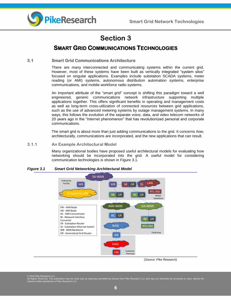
Many organizational bodies have proposed useful architectural models for evaluating how networking should be incorporated into the grid. A useful model for considering communication technologies is shown in Figure 3.1.
Figure 3.1 Smart Grid Networking Architectural Model
(Source: Pike Research)
Smart Grid Network Technologies
© 2010 Pike Research LLC. All Rights Reserved. This publication may be used only as expressly permitted by license from Pike Research LLC and may not otherwise be accessed or used, without the express written permission of Pike Research LLC.
7
The model portrays a four-tier network hierarchy, which may or may not correspond to any given physical implementation. The major functional areas are:
Substation WAN (SA-WAN) – A backbone wide-area network (WAN), often used to connect major substations as well as other enterprise office facilities. Usually designed to meet the bandwidth and latency requirements for major substation protection switching, backhaul of other grid communications, and enterprise voice/video/data traffic.
Substation LAN – Local area network (LAN) used to connect various devices (i.e. SCADA devices) within the substation.
Enterprise LAN - The usual enterprise LAN found within any major business, usually based on a hierarchy of switched Ethernet.
Distribution Automation WAN (DA-WAN) – The infrastructure supporting distribution automation communications, typically some form of SCADA.
AMI WAN (AMI-WAN) – WAN used to backhaul traffic from the various AMI concentrator nodes to the enterprise control center
AMI Neighborhood Area Network (NAN) – Networking connecting each smart meter to the associated concentrator node (if used).
Home Area Network – Customer premise connecting devices with the home of commercial energy network.
Note there are other communication networks relevant to the smart grid not necessarily covered by this model, including mobile workforce communications and inter-utility wide-area communications.
3.1.2 Smart Grid Communication Standards
Many, if not most, of today’s grid communications systems are proprietary. This is quickly changing as all industry stakeholders are actively driving toward a cohesive set of standards. The National Institute of Standards and Technology (NIST), as mandated by the U.S. Energy Independence and Security Act (EISA) of 2007, is perhaps the most significant effort. NIST is first identifying, within a specific architectural framework, which existing standards should be adopted for broader use within the Smart grid, and second, identifying standards gaps and prioritizing the filling of these gaps through existing industry standards bodies. This effort has fostered unprecedented participation and cooperation within the industry.
Just as the telecom industry wrestled with the shift from purpose-built networks to open data networks, the utility industry is grappling with adoption of the Internet Protocol (IP) suite within the smart grid. The widespread use of IP is at the heart of the NIST efforts, as IP can be the common denominator facilitating interoperability between fragmented automation systems in the utility network.
Smart Grid Network Technologies
© 2010 Pike Research LLC. All Rights Reserved. This publication may be used only as expressly permitted by license from Pike Research LLC and may not otherwise be accessed or used, without the express written permission of Pike Research LLC.
8
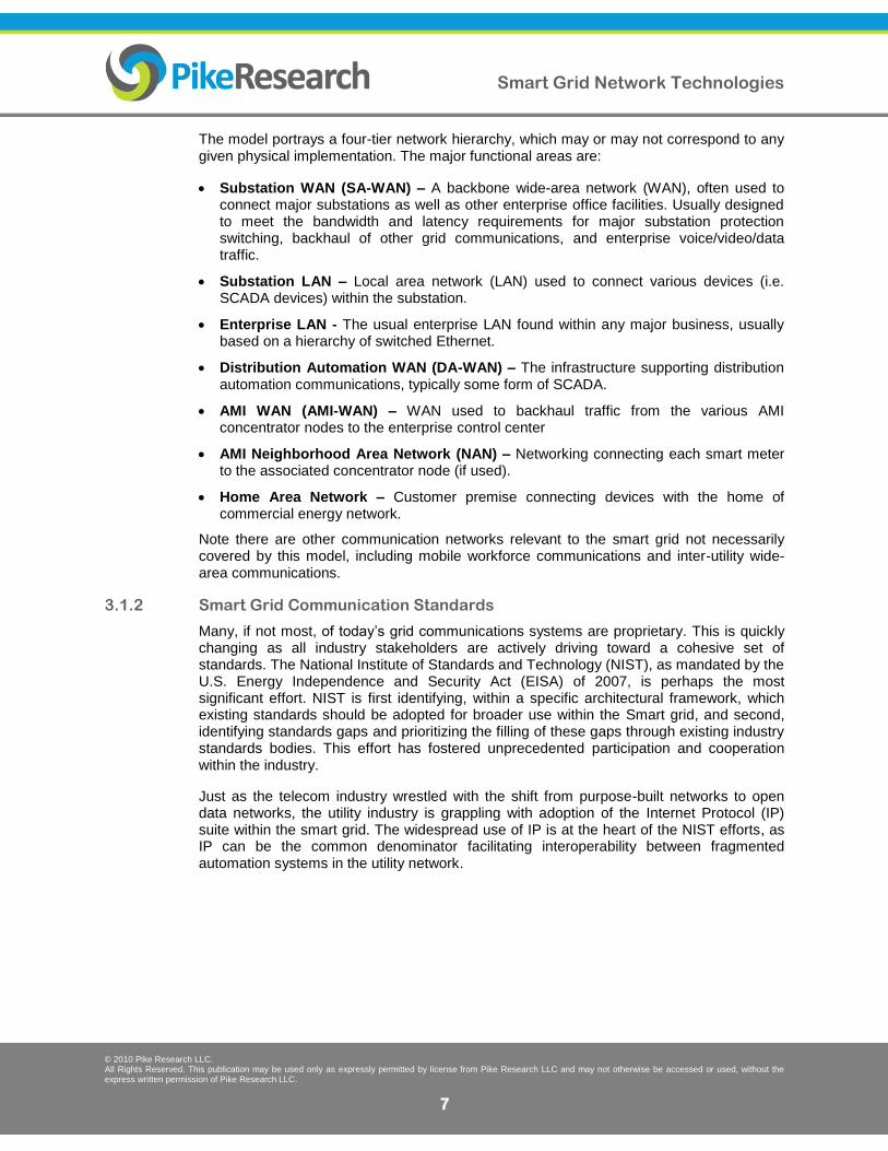
Figure 3.2 NIST Smart Grid Framework 1.0
(Source: NIST Framework and Roadmap for Smart grid Interoperability Standards Release 1.0 (Draft), September 2009)
3.2 Survey of Smart Grid Networking Technologies
A brief survey of the wide range of communications technologies use in the smart grid is provided here.
3.2.1 Wired Technologies
Utilities make use of a wide range of different public and private wired technologies in their networks:
Leased Lines and Broadband - The utility industry has made extensive use of leased telecom lines within their own private networks. Today, these are used to connect early substation automation systems (and other independently “siloed” systems) to the utility central control center. While many other industries have moved much of this connectivity (usually for Internet data and/or voice access) to newer xDSL or cable technologies, utilities have been slower to do so due to a lack of bandwidth demand by existing SCADA applications, lack of broadband availability at remote grid locations, and fear of hidden dependencies by older SCADA implementations on serial communications.
Despite the relatively good reliability delivered by traditional leased lines, many utilities are increasingly wary of using public infrastructure for critical grid communications. Utilities are concerned that the public network might be unreliable when needed most, such as during storm outages or other natural disasters. Also, many carriers want to discontinue traditional leased line services as they move toward packet-based infrastructures, leaving utilities to find alternatives or pay significant increases to already high rental fees.
Smart Grid Network Technologies
© 2010 Pike Research LLC. All Rights Reserved. This publication may be used only as expressly permitted by license from Pike Research LLC and may not otherwise be accessed or used, without the express written permission of Pike Research LLC.
9
Private Fiber - In some cases, utilities have deployed their own fiber cables within their own power line rights-of-way, and can leverage these for their own private networks. This is often used to connect major substations, with dedicated fiber used for the most sensitive protection switching applications, and dedicated SONET equipment used for backbone communications. Fiber offers very high performance, reliability (if used with resilient technologies such as SONET), and security. However, it requires clear right-of-way access to install, and can be very expensive, especially over longer distances. Hence fiber is not practical for many more remote substations or in most distribution automation applications.
Narrowband Power Line Communications (PLC) - As the name suggests, PLC provides connectivity using existing power lines as the communications medium. There are many different types of systems (and terminologies) associated with power line communications, and nearly as many standards. Performance ranges from a few bits/sec to as high as 100 kbps. This technology is most often used to connect smart meters on the low-voltage side of distribution transformers, where an aggregation node uplinks to the utility network using a different networking technology. PLC systems are more popular in Europe and parts of Asia, which average more than 50 meters per distribution transformer, as compared to North America, which averages less than five meters per distribution transformer. PLC is less likely to be used for distribution and substation automation applications due to difficulties optimizing the technology for the range of medium-voltage electrical lines, as well as concerns over losing communications when needed most, such as when a power line fails.
Broadband over Power Line (BPL) - BPL systems generally are PLC systems supporting data rates over 1 Mbps. There is a long-running standards war over BPL technology for in-home use, and systems leveraging the distribution grid have long been discussed (and provisionally deployed) as another means of providing alternative “last-mile” broadband Internet and voice services. As these efforts have faded, due to both technical issues (including radio interference) and business model issues, BPL is seeing some new interest as a Smart grid technology. One potential application is as a fiber alternative between transmission substations, using the high-voltage transmission lines, which offer a relatively clean BPL communications medium. However, technology for this type of application is still in early stages of development.
3.2.2 Terrestrial Wireless Technologies
Wireless communications are used by virtually every utility to provide communications to distributed devices throughout the grid. A wide range of mostly proprietary technologies are used for utility wireless communications.
3.2.2.1 Private RF Mesh Networks
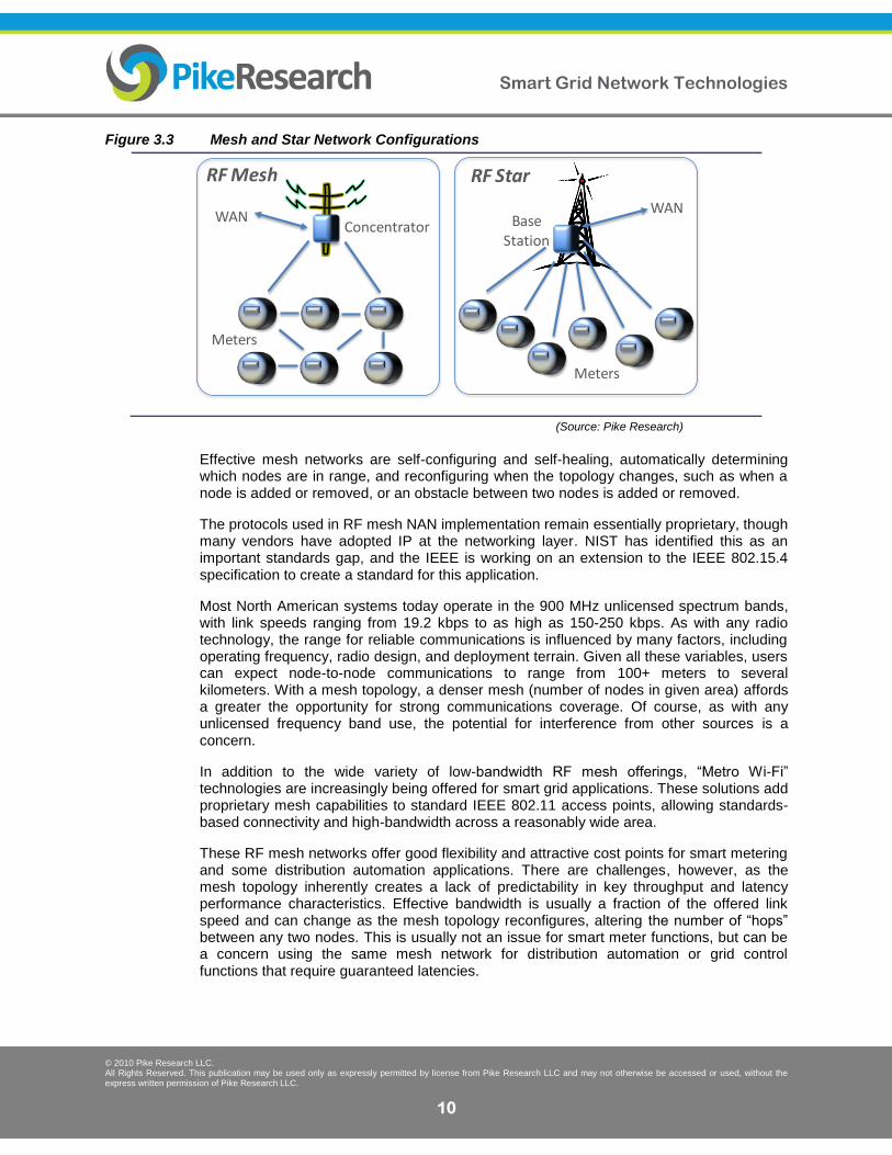
Radio frequency-based (RF) mesh networks have emerged as the leading NAN technology for smart metering applications. A mesh network forms a web-like network topology, as illustrated in Figure 3.3 Mesh and Star Network Configurations. Any node not in direct communication range of its target destination (such as a meter sending data to a concentrator) will have its data relayed by another node in the mesh (another meter, for example). A given data packet between a source and destination node may hop through many intervening nodes. Hence, the effective range of the network is extended well beyond the range of any single transmitter or receiver.
Smart Grid Network Technologies
© 2010 Pike Research LLC. All Rights Reserved. This publication may be used only as expressly permitted by license from Pike Research LLC and may not otherwise be accessed or used, without the express written permission of Pike Research LLC.
10
Figure 3.3 Mesh and Star Network Configurations
(Source: Pike Research)
Effective mesh networks are self-configuring and self-healing, automatically determining which nodes are in range, and reconfiguring when the topology changes, such as when a node is added or removed, or an obstacle between two nodes is added or removed.
The protocols used in RF mesh NAN implementation remain essentially proprietary, though many vendors have adopted IP at the networking layer. NIST has identified this as an important standards gap, and the IEEE is working on an extension to the IEEE 802.15.4 specification to create a standard for this application.
Most North American systems today operate in the 900 MHz unlicensed spectrum bands, with link speeds ranging from 19.2 kbps to as high as 150-250 kbps. As with any radio technology, the range for reliable communications is influenced by many factors, including operating frequency, radio design, and deployment terrain. Given all these variables, users can expect node-to-node communications to range from 100+ meters to several kilometers. With a mesh topology, a denser mesh (number of nodes in given area) affords a greater the opportunity for strong communications coverage. Of course, as with any unlicensed frequency band use, the potential for interference from other sources is a concern.
In addition to the wide variety of low-bandwidth RF mesh offerings, “Metro Wi-Fi” technologies are increasingly being offered for smart grid applications. These solutions add proprietary mesh capabilities to standard IEEE 802.11 access points, allowing standards-based connectivity and high-bandwidth across a reasonably wide area.
These RF mesh networks offer good flexibility and attractive cost points for smart metering and some distribution automation applications. There are challenges, however, as the mesh topology inherently creates a lack of predictability in key throughput and latency performance characteristics. Effective bandwidth is usually a fraction of the offered link speed and can change as the mesh topology reconfigures, altering the number of “hops” between any two nodes. This is usually not an issue for smart meter functions, but can be a concern using the same mesh network for distribution automation or grid control functions that require guaranteed latencies.
WAN
Meters
ConcentratorWAN
Meters
BaseStation
RF Mesh RF Star
Smart Grid Network Technologies
© 2010 Pike Research LLC. All Rights Reserved. This publication may be used only as expressly permitted by license from Pike Research LLC and may not otherwise be accessed or used, without the express written permission of Pike Research LLC.
11
3.2.2.2 Private Point-to-Point Microwave Radio Networks
Private point-to-point microwave links are commonly used between substations where fiber is impossible or uneconomical to install. These systems require good line-of-sight for antennas between the two locations, and effective data rates and distances vary with a range of technical choices.
Microwave links may use licensed or unlicensed spectrum. The latter spectrum has lower costs, but risks possible interference. Unlicensed frequencies range from 2.4 GHz (same as Wi-Fi, ZigBee, and Bluetooth) to as high as 60 GHz-70 GHz. The higher frequencies tend to have less potential interference, but also significantly reduced range. The lower frequency bands (2.4 GHz and 5.8 GHz) can achieve distances up to 20 miles.
Licensed microwave links require an FCC license, use of better (and more expensive) antennas to focus transmissions more effectively, and incur higher installation costs. However, they generally offer greater reliability due to a guarantee of no interference, and depending on equipment, can offer higher data rates.
3.2.2.3 Private RF Point-to-Multipoint Systems
Point-to-Multipoint systems are used for AMI, distribution automation, and some substation automation applications. Many of these use licensed radio spectrum allocations with greater allowed transmit power levels to enable communications between a centralized tower-based node and many devices within the range of that tower. This is referred to a “star” topology, where each node is within direct range of the center of a “star” (gateway) (See Figure 3.3)
Licensed spectrum can be expensive and difficult to obtain. Therefore, vendors of these private systems usually acquire and manage the rights to this spectrum themselves, allowing the utility customers to use it without the associated initial costs and regulatory hassles. Additionally, the frequencies used are usually in the 400 MHz and 900 MHz bands, though may be higher, with associated trade-offs in range (lower is usually better) and bandwidth (higher is usually better). Typical data rates – shared among potentially thousands of end nodes per tower – range from 4.8-9.6 kbps for traditional Multiple Address System (MAS) radios to as much as 300+ kbps for proprietary AMI-optimized systems.
These systems are typically configured so that each device has access to two or more gateways for redundancy, which are located on towers with antennas at heights of 200 to 650 feet, often sharing space with cellular infrastructure. Alternatively, gateways may be located on rooftops and other urban locations. The process and costs of obtaining tower access can be a significant undertaking in the deployment of these systems, as well as assuring that reasonable line-of-sight is possible to each end node.
WiMAX, an emerging broadband wireless technology for 4G public networks, is also finding use as a standards-based private wireless network for the smart grid. While some vendors hope to see WiMAX used directly to AMI meters, it is finding greater traction in AMI backhaul, substation automation, and distribution automation applications.
3.2.2.4 Cellular Networks
Mobile operators in the U.S. are becoming increasingly aggressive in targeting the smart grid market as part of their machine-to-machine (M2M) communications market push. M2M has long been a backwater of carrier operations, but a slowdown in mobile subscriber growth and declining costs-per-megabyte for delivering data over a cellular network are
Smart Grid Network Technologies
© 2010 Pike Research LLC. All Rights Reserved. This publication may be used only as expressly permitted by license from Pike Research LLC and may not otherwise be accessed or used, without the express written permission of Pike Research LLC.
12
driving another look at this opportunity. Meanwhile, utilities are more interested in cellular as a communications option because of the low capital investment, variable cost structure of purchasing connectivity by the megabyte, and the low cost, standardized modules and chips available for a wide variety of equipment and devices.
The cost of utilizing cellular network connectivity for smart meters still remains higher than with proprietary RF mesh networks, but cellular is widely used for AMI backhaul connectivity. In Europe, the lower cost and better coverage of cellular infrastructure is enabling deeper use in the smart grid.
While the efforts of public carriers to address smart grid applications is gaining some attention, most utilities remain very cautious about using public wireless infrastructure for critical communications, fearing for the system’s reliability or severe bandwidth contention during the moments most needed, such during some sort of public emergency or natural disaster. Full coverage over a utility’s full service footprint is also a concern.
The emergence of 4G technologies (WiMAX and LTE) will allow public wireless carriers to offer more robust bandwidth and security guarantees to utilities, however this is unlikely to see much adoption by utilities until the 4G build-outs are further along, and may not fully address utilities’ general concerns with public network reliability.
3.2.3 Satellite Communications
Satellite communication has long been used in utility networks to provide connectivity for SCADA and applications such as voice/video/data to remote substation sites that cannot be economically reached by other communications methods. Despite this history, satellite communication is often viewed as an exotic technology and overlooked as a smart grid communications option.
Today, satellite communications has recently undergone a major transformation and has evolved in improving performance reliability and reducing costs. Satellite networks are now two-way communications systems, built on IP, with broadband data rates. Next-generation coding standards have made satellite more reliable and cost efficient. Further, satellite networking hardware has been engineered to meet next-generation carrier standards, integrating well with terrestrial wireless and wireline communications.
Advances in satellite communications and in particular Very Small Aperture Terminal (VSAT) technologies have expanded the range of potential applications within the smart grid. These systems use small (often under one meter) antennas, simpler IP-compatible terminal equipment, and better performance than earlier satellite systems. These VSAT solutions provide:
Broad geographic coverage, including areas where standard wired and wireless technologies cannot reach.
Flexible data rate performance, ranging from 16 kbps suitable for basic SCADA connectivity to speeds of 1 Mbps and above in support of voice, video and general data applications. Performance is often further enhanced by bandwidth optimization technologies for IP communication, such as User Datagram Protocol (UDP) header compression.
Highly reliable connectivity, suitable for day-to-day operation or as a backup to terrestrial systems during disaster recovery situations.
Smart Grid Network Technologies
© 2010 Pike Research LLC. All Rights Reserved. This publication may be used only as expressly permitted by license from Pike Research LLC and may not otherwise be accessed or used, without the express written permission of Pike Research LLC.
13
Full IP-based integration with standard wired or wireless terrestrial networking technologies.
Lower entry cost due to dynamic bandwidth sharing techniques such as the Deterministic Time Division Multiple Access (TDMA) technology.
Terrestrial-grade SLAs based on advances in quality-of-service management that allow bandwidth prioritization by user, application, virtual LAN, IP address, or other identifiers, combined with static or dynamic Committed Information Rates (CIR).
Data security through the configuration of encrypted private networks, which is necessary for utilities to comply with the North American Electric Reliability Corporation (NERC) specifications. Support of MPLS and VLANs separates different users and/or applications (SCADA vs. generalized data) with their own bandwidth assurances.
Protection against weather conditions through adaptive modulation techniques that maintain signal strength during rain or solar events that sometimes occurred with older satellite technologies.
Utilities may build and operate their own private satellite network by leasing dedicated bandwidth from satellite operators such as Intelsat and SES. If deploying a larger number of satellite terminals, a self-managed network can be very cost effective. However, for smaller networks, working through a satellite network provider is an attractive alternative due to the bandwidth economies of scale inherent in an existing provider’s larger network deployment.
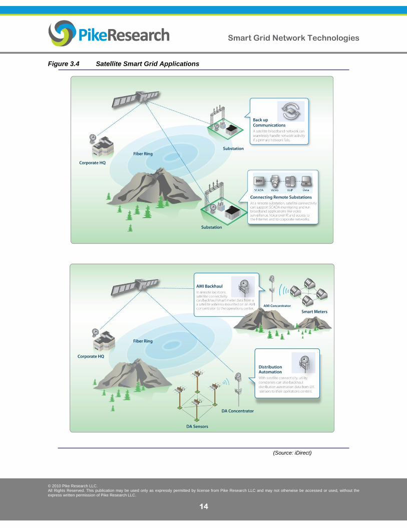
In addition to supporting sites such as substations and power generation plants, satellite is an increasingly viable option for other smart grid applications, including:
Broadband connectivity to remote substations to support video surveillance, and voice and data connectivity to increase security and productivity.
AMI backhaul from meter aggregation nodes, especially in more remote, rural areas where other technologies may not be cost effective.
Distribution Automation connectivity, ensuring connectivity throughout the service territory.
Monitoring and control of remote renewable generation sites, such as solar or wind farm management.
Business continuity applications, providing links to backup Network Operations Centers (NOCs) during emergency response or disaster recovery situations.
Redundant communications at critical substation and distribution sites to backup terrestrial communications.
It is worth noting that “remote” sites are not necessarily limited to sites in rural or geographically remote locations. Sometimes locations in urban centers have limitations that make standard wired technologies economically unfeasible, including right-of-way access, line-of-sight, or interference issues. In these cases, satellite can be a viable option.
Smart Grid Network Technologies
© 2010 Pike Research LLC. All Rights Reserved. This publication may be used only as expressly permitted by license from Pike Research LLC and may not otherwise be accessed or used, without the express written permission of Pike Research LLC.
14
Figure 3.4 Satellite Smart Grid Applications
(Source: iDirect)
Smart Grid Network Technologies
© 2010 Pike Research LLC. All Rights Reserved. This publication may be used only as expressly permitted by license from Pike Research LLC and may not otherwise be accessed or used, without the express written permission of Pike Research LLC.
15
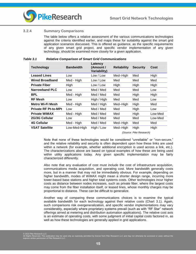
3.2.4 Summary Comparisons
The table below offers a relative assessment of the various communications technologies against the criteria identified earlier, and maps these for suitability against the smart grid application scenarios discussed. This is offered as guidance, as the specific requirements of any given smart grid project, and specific vendor implementation of any given technology, should be examined more closely for a given application.
Table 3.1 Relative Comparison of Smart Grid Communications
Technology Bandwidth Latency (Amount / Variability)
Reliability Security Cost
Leased Lines Low Low / Low Med–High Med High
Wired Broadband Med - High Low / Low Med Med Med
Private Fiber High Low / Low High High High
Narrowband PLC Low Med / Med Med Med Low
BPL Med - High Med / Med Med High High
RF Mesh Low High / High Med Med Low
Metro Wi-Fi Mesh Med - High Med / High Med–High High Med
Private RF Pt-to-MPt Low Med / Med Med High Low
Private WiMAX Med - High Med / Med Med High Low-Med
2G/3G Cellular Low Med / Med Med Med Low-Med
4G Cellular Med - High Med / Med Med–High Med Med
VSAT Satellite Low-Med-High High / Low Med–High High High
(Source: Pike Research)
Note that none of these technologies would be considered “unreliable” or “non-secure,” and the relative reliability and security is often dependent upon how these links are used within a network (for example, whether additional encryption is used across a link, etc.). The characterizations above are based on typical examples of how these are being used within utility applications today. Any given specific implementation may be fairly characterized differently.
Also note that any evaluation of cost must include the cost of infrastructure acquisition, communications media acquisition, and operating cost. More bandwidth generally costs more, but in a manner that may not be immediately obvious. For example, depending on higher bandwidth, modes of WiMAX might mean a shorter design range, incurring more tower-based base stations and higher total systems costs. Other technologies incur higher costs as distance between nodes increases, such as private fiber, where the largest costs may come from the fiber installation itself, or leased lines, whose monthly charges may be proportional to distance. These can be difficult to generalize.
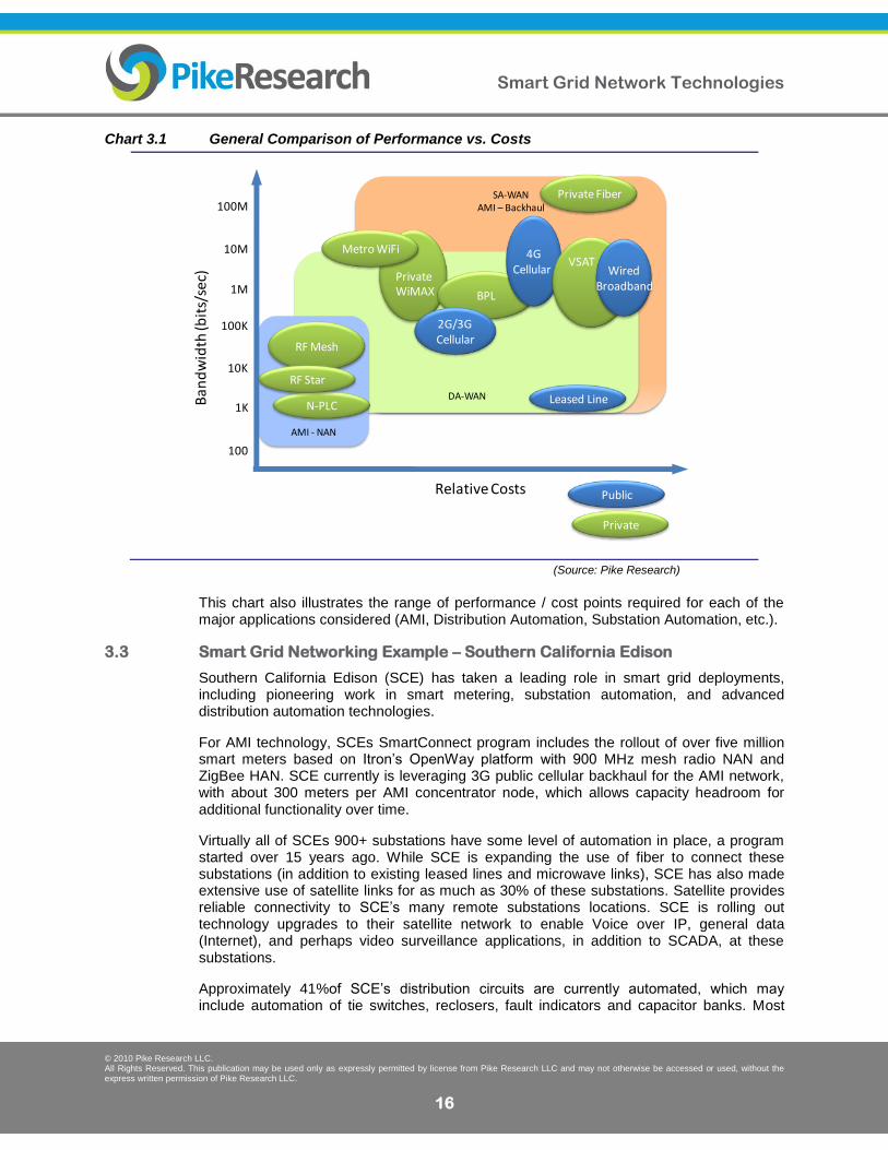
Another way of comparing these communications choices is to examine the typical available bandwidth for each technology against their relative costs (Chart 3.1). Again, such comparisons risk overgeneralization, and specific vendor implementations may vary considerably, especially where proprietary systems prevail (such as with “RF Star” network offerings aimed at metering and distribution automation applications). The relative cost axis is an estimate of operating costs, with some judgment of initial capital costs factored in, as well as how these technologies are generally applied in grid applications.
Smart Grid Network Technologies
© 2010 Pike Research LLC. All Rights Reserved. This publication may be used only as expressly permitted by license from Pike Research LLC and may not otherwise be accessed or used, without the express written permission of Pike Research LLC.
16
Chart 3.1 General Comparison of Performance vs. Costs
(Source: Pike Research)
This chart also illustrates the range of performance / cost points required for each of the major applications considered (AMI, Distribution Automation, Substation Automation, etc.).
3.3 Smart Grid Networking Example – Southern California Edison
Southern California Edison (SCE) has taken a leading role in smart grid deployments, including pioneering work in smart metering, substation automation, and advanced distribution automation technologies.
For AMI technology, SCEs SmartConnect program includes the rollout of over five million smart meters based on Itron’s OpenWay platform with 900 MHz mesh radio NAN and ZigBee HAN. SCE currently is leveraging 3G public cellular backhaul for the AMI network, with about 300 meters per AMI concentrator node, which allows capacity headroom for additional functionality over time.
Virtually all of SCEs 900+ substations have some level of automation in place, a program started over 15 years ago. While SCE is expanding the use of fiber to connect these substations (in addition to existing leased lines and microwave links), SCE has also made extensive use of satellite links for as much as 30% of these substations. Satellite provides reliable connectivity to SCE’s many remote substations locations. SCE is rolling out technology upgrades to their satellite network to enable Voice over IP, general data (Internet), and perhaps video surveillance applications, in addition to SCADA, at these substations.
Approximately 41%of SCE’s distribution circuits are currently automated, which may include automation of tie switches, reclosers, fault indicators and capacitor banks. Most
SA-WAN AMI – Backhaul
DA-WAN
AMI - NAN
Leased Line
PrivateWiMAX
N-PLC
BPL
RF Mesh
Metro WiFi
RF Star
2G/3G Cellular
4G Cellular
100
1K
10K
100K
1M
10M
100MPrivate Fiber
Ban
dw
idth
(bit
s/se
c)
Relative Costs Public
Private
VSAT Wired
Broadband
Smart Grid Network Technologies
© 2010 Pike Research LLC. All Rights Reserved. This publication may be used only as expressly permitted by license from Pike Research LLC and may not otherwise be accessed or used, without the express written permission of Pike Research LLC.
17
communications use a 900 MHz RF mesh network based on the Landis+Gyr (formerly Cellnet) UtiliNet radio system. Over 40,000 radio nodes are deployed, and are currently maintained separately from the AMI network system.
SCE was awarded ARRA stimulus funding for its Irvine Smart Grid Demonstration (SGD) project, targeted as a “deep vertical dive” into end-to-end smart grid technologies that leverage SCE’s experience in smart metering, distribution automation (via an early “Avanti distribution circuit” project), and synchrophasor development. This project will evaluate a variety of communications technologies, including WiMAX for some distribution and substation automation, AMI backhaul, and perhaps even into the home connectivity. Expanded use of SCE satellite network is also being evaluated for AMI backhaul and distribution automation applications, particularly in regions where other wireless coverage is weak or not feasible.
Smart Grid Network Technologies
© 2010 Pike Research LLC. All Rights Reserved. This publication may be used only as expressly permitted by license from Pike Research LLC and may not otherwise be accessed or used, without the express written permission of Pike Research LLC.
18
Section 4
CONCLUSIONS AND RECOMMENDATIONS
The evolution of the smart grid will continue to leverage a wide variety of different communications technologies, though as emerging standards take hold, the number of proprietary systems will likely decrease. However, utility preference for their own private networks is likely to continue until public carriers can deliver the coverage, service level guarantees, and cost points required.
Smart grid networking choices are likely to converge around four primary technology groupings:
1) Private, purpose-built mesh or star RF networks (mostly in North America) and PLC networks (mostly in Europe), aimed at smart meter connectivity at the neighborhood level (AMI-NAN). Proprietary today, these will eventually use emerging standards.
2) Standards-based radio networks for field-level connectivity (AMI backhaul and distribution automation connectivity). Proprietary systems will give way to standard, IP-based solutions leveraging established standards including private WiMAX and Wi-Fi, and public wireless 3G and 4G offerings.
3) High-speed fiber, where possible, for substation connectivity and as a backbone / backhaul for field-level connectivity.
4) Satellite communications as a flexible and reliable solution in field-area (AMI-backhaul and Distribution Automation) and substation applications, especially where the total cost, performance, reliability, and/or availability of traditional wired or terrestrial wireless technologies fall short. Advances in satellite technology and cost-effectiveness are likely to increase the percentage of satellite use within the smart grid communications mix.
Utilities planning integrated smart grid network infrastructures need to clearly identify and balance the relative cost, performance (both for bandwidth and latency), coverage, reliability, and security requirements against the variety of choices available. Standard, IP-based, and adaptable technologies should be given a preferential place in any evaluation. Modern satellite communications options should be evaluated as part of smart grid communications architecture.

Smart Grid Network Technologies
© 2010 Pike Research LLC. All Rights Reserved. This publication may be used only as expressly permitted by license from Pike Research LLC and may not otherwise be accessed or used, without the express written permission of Pike Research LLC.
19
Section 5
APPENDIX SMART GRID APPLICATIONS AND USE CASES
5.1 Smart Grid Applications and Use Cases
The basic electrical grid structure can be divided into the following major components:
A) Generation – any type of major generation plant: coal, hydro, gas, etc. Facilities may
be owned by a vertically integrated utility or separate generation companies.
B) Transmission – high-voltage aimed at long-distance, high-capacity transmission. Transmission substations convert the high-voltage levels to sub-transmission levels of typically 55kV to 138kV.
C) Distribution – Infrastructure including:
Distribution substations, located throughout a utility’s service territory, that convert the sub-transmission voltage levels to lower voltages used for distribution feeder circuits into the service neighborhoods.
Distribution feeder circuits, including various distributed devices (switches, reclosers, sectionalizers, capacitors, etc.) to control and condition power distribution.
Distribution transformers, located on poles, ground-level, or underground, that convert the distribution feeder voltage to the service voltage (110/220V in NA, serving 3-5 homes, or 220/480V in Europe, serving ~50 homes).
D) Residential and Commercial Consumers – Residential homes or businesses, each
equipped with an individual meter(s).
5.1.1 Smart Metering and AMI
Smart meters are an evolution of the standard electrical meter combining integrated intelligence (computing and data storage) with two-way communications between the meter and the utility’s head-end IT systems. This intelligence and communication enables remote reading at frequent intervals (at least once per hour) and control of the meter. Smart meters are provided as part of Advanced Meter Infrastructure (AMI), and promise many benefits to utilities and consumers, including:
Reduced meter reading labor costs
Increased meter reading frequency and accuracy
Remote connect/disconnect and load limiting capabilities
Automated outage detection
Power quality monitoring, outage prevention, and load planning
Theft prevention
Though smart meter operating expense savings is important, most of the attention today is on the smart meter’s role in empowering consumers to understand and react to their own energy consumption, and perhaps even have devices in their homes react automatically.

Smart Grid Network Technologies
© 2010 Pike Research LLC. All Rights Reserved. This publication may be used only as expressly permitted by license from Pike Research LLC and may not otherwise be accessed or used, without the express written permission of Pike Research LLC.
20
Smart meters provide the information necessary to offer consumers incentives to conserve and/or shift their power use, and even support their own distributed power generation.
5.1.2 Substation Automation
The basic function of an electrical substation is to transform the voltage levels between the transmission, sub-transmission, and/or distribution parts of the electrical network. However, there are many additional devices and functions linked into a substation to provide for the safety and stability of the system. Components found in typical substations may include: transformers, circuit breakers, protective relays, disconnect switches, voltage regulators, regulators with load tap changes (LTCs), capacitor banks, reactors, and static VAR compensators (SVC).
Substations vary in size and complexity based on the type (transmission or distribution), purpose (residential or industrial), location (above ground in a dedicated yard, underground, or if very small, pole mounted), and service territory (number of distribution feeders supported, etc.). While many substations are manually configured and controlled, increasingly, these systems are being automated with networking technology.
5.1.2.1 SCADA Systems
Supervisory Control and Data Acquisition (SCADA) refers to computer-based control systems used in a wide variety of industrial monitoring and process control applications, including electrical utility substations. The sensing, control, and computing devices that are part of SCADA systems are connected by some form of local and/or wide-area network communications. The general structure of a SCADA system is illustrated in Error! Reference source not found..
Figure 5.1 SCADA System General Layout
(Source: Guide to Industrial Control Systems (ICS) Security, NIST Special Publication 800-82, September 2008)
The communications within the SCADA system vary considerably and are evolving. Initially based on proprietary protocols over serial lines, most systems today leverage an Ethernet Local Area Network (LAN) within the substation.
The wide area network connections also vary considerably, with many larger substations
Smart Grid Network Technologies
© 2010 Pike Research LLC. All Rights Reserved. This publication may be used only as expressly permitted by license from Pike Research LLC and may not otherwise be accessed or used, without the express written permission of Pike Research LLC.
21
connected by redundant high-speed fiber connections, while smaller distribution substations may use leased telecom lines running as slow as 1200 baud, if connected at all. Increasingly, larger substations are seen as a logical communications network aggregation point for AMI backhaul, Wide Area Network (WAN) interconnection, and distribution automation networks.
While most current substation communications are relatively low-bandwidth, a significant exception is protection relay communications between substations, where a device at a distant substation may need to react to a fault within a fraction a single AC cycle time (60Hz cycle = ~16msec). These links often use a dedicated pair of fiber lines between substations.
5.1.3 Distribution Automation
Distribution circuits connect the local substations to the energy customers. The distribution lines may be overhead and/or underground, and vary in length and number of end-customers served (typically 700-1500 per distribution feeder). Their topological and electrical design is similarly diverse. These include radial systems that branch out from substations (as a spoke on a wheel), loop systems with some redundancy through a normally-open connection downstream between two feeders that allows load to be shifted between them if a break occurs, and “primary networks” consisting of a grid of interconnected primary feeders supplied by different substations for very high service reliability requirements (found in select urban areas).
The devices included on distribution circuits may include distribution transformers, reclosers, sectionalizers, disconnect switches, voltage regulators, capacitor banks, fault sensors, and fused cutout switches.
Basic distribution automation consists of equipping the various distribution feeder devices with communications for remote sensing and control. The devices may have inherent control and communications capability, and/or use “bolt-on” controls (such as remotely activated motors to crank manual switches, etc.) to implement the desired automation.
More advanced distribution automation applications may include:
Automatic Restoration - Reclosers and sectionalizers automatically restore service to portions of a faulted circuit by identifying the fault location and isolating it from the remainder of the circuit. Independent fault sensors on each segment provide indication to an operations center that such a fault occurred.
Dynamic Feeder Reconfiguration - Distribution circuits with redundant circuit paths can leverage communications and control capabilities to automatically sense a segment fault, and automatically reconnect the remaining segments to another redundant feeder.
Conservation Voltage Reduction (CVR) – The regulated voltage set on each distribution feeder must account for losses along the length of the line. Generally, this is set statically to a conservative level to assure minimum voltage levels are maintained along the entire feeder length. However, if the voltage can be managed dynamically, the relatively large “guard bands” can be significantly reduced. Power reductions of as much as 0.7-0.9% per % of voltage reduction can be achieved.
1
1 As presented to Utah Public Utilities Commission Smart grid Workshop, May 2009, by Rob Pratt Pacific Northwest National
Laboratory.
Smart Grid Network Technologies
© 2010 Pike Research LLC. All Rights Reserved. This publication may be used only as expressly permitted by license from Pike Research LLC and may not otherwise be accessed or used, without the express written permission of Pike Research LLC.
22
VAR Control – VAR (voltage-ampere reactive) is a measure of reactive power, more of which is needed to maintain a given voltage on distribution line as the length of that line increases. Capacitor banks placed along a longer distribution line reduces the reactive power losses and dynamically controlling such capacitors allows such “VAR Control” to be optimized.
5.1.4 Related Grid Communications Applications
There are many other communications applications within the smart grid, including:
General Voice and Data Communications - Like any organization, utilities maintain standard voice, data, and increasingly, video communications networks. These networks have similar requirements to any other enterprise with multiple sites (customer offices, remote service facilities, etc.), but uniquely, these often are extended to remote substation and distribution sites throughout the service territory.
Outage and Fault Management Systems - IT systems that leverage data from field networks to manage outage situations.
Asset Management and Tracking - Internal systems to indentify and manage the huge number of physical assets deployed throughout the grid system.
Workforce Automation and Communications - Utilities have large, mobile, workforces with strong needs for central dispatch and coordination. This is required for safety, as well as efficient work management.
Smart Grid Network Technologies
© 2010 Pike Research LLC. All Rights Reserved. This publication may be used only as expressly permitted by license from Pike Research LLC and may not otherwise be accessed or used, without the express written permission of Pike Research LLC.
23
Section 6
ABOUT THE SPONSOR
iDirect is a world leader in satellite-based IP communications technology. Our products and services help to transform the way the world gets and stays connected. With more than 15 years of global satellite communications experience, we serve customers in over 50 countries through a diverse network of service provider partners, including seven of the World Teleport Association’s Global Top Ten operators. Headquartered in Herndon, Virginia, we have offices in Europe, Middle East, Africa and Latin America.
We partner with utilities to provide customized communication solutions to help meet smart grid objectives. Through our technology, utility companies gain a secure and more reliable network solution to monitor SCADA (Supervisory Control and Data Acquisition) devices, with the ability to extend broadband applications such as video surveillance, VoIP and corporate data access to remote substations. iDirect’s technology can also be leveraged by utility companies to support the need to backhaul smart meter data from aggregation sites and manage green energy sites. And it is also relied on by utilities to provide back-up communications in the wake of disasters and communication circuit failures.
Smart Grid Network Technologies
© 2010 Pike Research LLC. All Rights Reserved. This publication may be used only as expressly permitted by license from Pike Research LLC and may not otherwise be accessed or used, without the express written permission of Pike Research LLC.
24
Section 7
TABLE OF CONTENTS
Section 1 ...................................................................................................................................................... 2 Introduction ................................................................................................................................................. 2 Section 2 ...................................................................................................................................................... 3 Smart Grid Applications and Communication Requirements ............................................................... 3
2.1 The Smart Grid .............................................................................................................................. 3 2.1.1 Smart Grid Communications Drivers ....................................................................................... 3 2.1.2 Smart Grid Applications ........................................................................................................... 4
2.2 Smart Grid Communications Requirements ................................................................................. 4 Section 3 ...................................................................................................................................................... 6 Smart Grid Communications Technologies ............................................................................................. 6
3.1 Smart Grid Communications Architecture ..................................................................................... 6 3.1.1 An Example Architectural Model ............................................................................................. 6 3.1.2 Smart Grid Communication Standards ................................................................................... 7
3.2 Survey of Smart Grid Networking Technologies ........................................................................... 8 3.2.1 Wired Technologies ................................................................................................................. 8 3.2.2 Terrestrial Wireless Technologies ........................................................................................... 9 3.2.3 Satellite Communications ...................................................................................................... 12 3.2.4 Summary Comparisons ......................................................................................................... 15
3.3 Smart Grid Networking Example – Southern California Edison .................................................. 16 Section 4 .................................................................................................................................................... 18 Conclusions and Recommendations ...................................................................................................... 18 Section 5 .................................................................................................................................................... 19 Appendix Smart Grid Applications and Use Cases ............................................................................... 19
5.1 Smart Grid Applications and Use Cases ..................................................................................... 19 5.1.1 Smart Metering and AMI ....................................................................................................... 19 5.1.2 Substation Automation .......................................................................................................... 20 5.1.3 Distribution Automation ......................................................................................................... 21 5.1.4 Related Grid Communications Applications .......................................................................... 22
Section 6 .................................................................................................................................................... 23 About the Sponsor .................................................................................................................................... 23 Section 7 .................................................................................................................................................... 24 Table of Contents ...................................................................................................................................... 24 Section 8 .................................................................................................................................................... 25 List Of Figures, Tables, and Charts ........................................................................................................ 25

Smart Grid Network Technologies
© 2010 Pike Research LLC. All Rights Reserved. This publication may be used only as expressly permitted by license from Pike Research LLC and may not otherwise be accessed or used, without the express written permission of Pike Research LLC.
25
Section 8
LIST OF FIGURES, TABLES, AND CHARTS
Figure 3.1 Smart Grid Networking Architectural Model ............................................................................ 6 Figure 3.2 NIST Smart Grid Framework 1.0 ............................................................................................. 8 Figure 3.3 Mesh and Star Network Configurations ................................................................................ 10 Figure 3.4 Satellite Smart Grid Applications ........................................................................................... 14 Figure 5.1 SCADA System General Layout ........................................................................................... 20
Table 2.1 Communications Requirement Descriptions ........................................................................... 4 Table 2.2 Smart Grid Communications Requirements Summary ........................................................... 5
Chart 3.1 General Comparison of Performance vs. Costs .................................................................... 16

Smart Grid Network Technologies
© 2010 Pike Research LLC. All Rights Reserved. This publication may be used only as expressly permitted by license from Pike Research LLC and may not otherwise be accessed or used, without the express written permission of Pike Research LLC.
26
Published 3Q 2010
©2010 Pike Research LLC 1320 Pearl Street, Suite 300
Boulder, CO 80302 USA Tel: +1.303.997.7609
http://www.pikeresearch.com
This publication is provided by Pike Research LLC (“Pike”). This publication may be used only as expressly permitted by license from Pike and may not otherwise be reproduced, recorded, photocopied, distributed, displayed, modified, extracted, accessed or used without the express written permission of Pike. Notwithstanding the foregoing, Pike makes no claim to any Government data and other data obtained from public sources found in this publication (whether or not the owners of such data are noted in this publication). If you do not have a license from Pike covering this publication, please refrain from accessing or using this publication. Please contact Pike to obtain a license to this publication.