section 1 - general draft jfiles.hawaii.gov/luc/dockets/a83557princeville_dev_corp/...page 4 draft...
TRANSCRIPT

SECTION 1 - GENERAL DRAFT
6. Coordination of the test boring exploration and logging of the borings by our field geologist.
7. Laboratory testing of selected samples obtained during the field exploration as an aid in classifying the materials and evaluating their engineering properties.
8. Analyses of the field and laboratory data to formulate preliminary geotechnical recommendations for slope stability and the design of foundations, retaining structures, site grading, and pavements.
9. Preparation of this report summarizing our work on the project and presenting our findings and recommendations.
10. Coordination of our overall work on the project by our project manager.
11. Quality assurance of our work and client/design team consultation by our principal engineer.
12. Miscellaneous work efforts such as drafting, word processing, and clerical support.
Detailed description of our current test boring exploration and the Logs of Borings
(B-101 through B-116) are presented in Appendix A. Detailed description of our
previous test boring exploration conducted at the Eastem Plateau and the associated
Logs of Borings (B-1 through B-5) are presented in Appendix B. Description and
summary information pertaining to our previous test pit field exploration at Landfill Areas
I and II are presented in Appendix C. The results of the laboratory tests performed on
selected soil samples collected at the project site are presented in Appendix D. And
finally, the results of the previous laboratory tests performed on selected soil samples
collected at the Eastern Plateau are presented in Appendix E.
END OF GENERAL
W.O. 5742-00(A) GEOLABS, INC. Page 4
DRAFT
SECTION 2.0 - SITE CHARACTERIZATION J
2.1 Regional Geology
The Island of Kauai is essentially a dissected basaltic dome that was initially
formed by a single large shield volcano, which has subsequently been deeply eroded
and partially covered with later (younger) volcanic materials. The Island of Kauai is the
oldest of the main Hawaiian Islands and today encompasses approximately 555 square
miles with a maximum elevation of about 5,170 feet above Mean Sea Level at
Mount Waialeale, near the center of the island. It is believed that during the
Tertiary Period (about 5 to 6 million years ago during the Pliocene Epoch), basaltic
lavas belonging to the Waimea Canyon Volcanic Series built a roughly circular island
volcano from the ocean floor, which is estimated to have been about 20,000 feet deep
at the time. Near the end of the Pliocene Epoch, this main shield building volcanic
phase came to a halt.
Following a long period of erosion and island mass subsidence, volcanism was
renewed during the early Pleistocene Epoch (about 1.5 million years ago) with the
eruption of the Koloa Volcanic Series from multiple vents located throughout the island.
This post-erosional volcanic activity laid a veneer of fresh lava and interbedded volcanic
sediments over the older deposits of the Waimea Canyon Series. Because of the long
period of erosion that occurred between the eruption of the Waimea Volcanic Series
and the Koloa Volcanic Series, the deposits of the Koloa Volcanic Series typically filled
the erosional valleys and depressions, which existed at that time. Consequently, the
basaltic rocks of the Koloa Volcanic Series are commonly found to overlie thick residual
soil and alluvial deposits.
The dominant geologic processes of weathering, landform erosion, and sediment
re-deposition followed during the late Pleistocene and Recent Epochs. Combined with
the erosional and depositional effects of the Pleistocene sea-level fluctuations, which
occurred in response to the worldwide advance and retreat of the continental ice sheets,
the Island of Kauai has evolved to its present form.
W.O. 5742-00(A) GEOLABS, INC. Page 5

SECTION 2 - SITE CHARACTERIZATION DRAFT
The project site encompasses a distinct geographic region that is herein referred
to as the upland plateau region. This upland plateau region consists of a broad gently
sloping plateau that has been dissected by deep sinuous drainage ravines that have
produced steep ravine side slopes. The drainage ravines deepen over relatively short
distances beginning as gentle depressions at their headland sources (at the southern
portion of the site) and dropping to deep valley floors over 200 feet in depth (at the
northem portion of the site).
Based on a review of available geologic information, the project site is generally
underlain by a thick sequence of extremely weathered basaltic rock (saprolite)
belonging to the Koloa Volcanic Series. The soil materials generally consist of in-situ
basalt rock that has been deeply weathered to form silty and clayey saprolitic soils with
embedded decomposed rock material. These saprolitic deposits extend for considerable
depth below the upland ground surfaces. Due to the high rainfall and runoff experienced
at this northern portion of the Island of Kauai, the in-situ saprolitic soils have high
moisture contents. In addition, groundwater seepage and high-level perched
groundwater are commonly encountered in the subsurface saprolitic materials. These
groundwater conditions contribute to the formation of spring discharge at lower
elevations and near-continual stream discharge, which occurs in the larger drainages.
2.2 Site Description
The project site is in the Princeville area in the District of Hanalei on the Island of
Kauai, Hawaii as shown on the Project Location Map, Plate 1. The project site is north
through northwest of the existing Princeville Airport and encompasses the broad upland
region referred to as the Eastern and Central Plateaus. The project site covers
approximately 800 acres of mostly vacant land, which was formerly used for crop
cultivation and pasture land. The project site is in an area characteristic of very high
rainfall and humid climate conditions. As a result, groundwater seepage from slopes
and relatively high soil moisture contents are characteristic of the project site.
The interior plateau encompasses multiple bluffs that slope down very gently
toward the north before transitioning to steeper northerly facing slopes above the
W.O. 5742-00(A) GEOLABS, INC. Page 6
SECTION 2 - SITE CHARACTERIZATION DRAFT
Anini and Kalihikai coastal areas. Sinuous incised drainage valleys and topographic
depressions, which generally drain toward the north between Anini and Kalihikai
Beaches, separate the individual bluffs. The bounding valleys, drainage ravines, and
depressions are typically densely forested with large trees. The tops of the bluffs
generally consist of open grass rangeland interspersed with forested terrain mainly
along the margins and within the drainage valleys. The existing bluff tops slope gently
toward the north at about a 2 to 4 degree inclination. Side slopes bordering the ravines
and depressions typically stand at inclinations ranging between approximately
one horizontal to one vertical (1H:1V) to 4H:1V, with the steepest slopes bounding the
northern perimeter of the project site.
Elevations at the project site generally range between about +340 and +200 feet
Mean Sea Level (MSL). In general, the existing valley and ravine side slopes appear to
stand at inclinations of about 1 H:1V or flatter and are mostly covered with surface
vegetation and trees. Our visual observations revealed only localized widely scattered
exposures of shallow depth earthen slides existing on portions of the upper elevation
slopes. We did not observe visible evidence of large-scale slope instability within the
project site or visible evidence of surface groundwater seepage; however, groundwater
spring discharges may be encountered on the valley side slopes, especially at lower
elevations. The approximate limits of the proposed Princeville Grand Estates
Subdivision are shown on the Site Plan, Plate 2.
As previously mentioned, the upland plateau region resides as mainly
undeveloped pasture and forested land. The exception is a partially developed area at
the southeast comer of the project site and westerly of the existing Anini Vista Road.
The area contains a concrete batch plant and a stockpile site for soil and gravel
materials within Lot Nos. 9A and 10A as shown on the Site Plan, Plate 2.
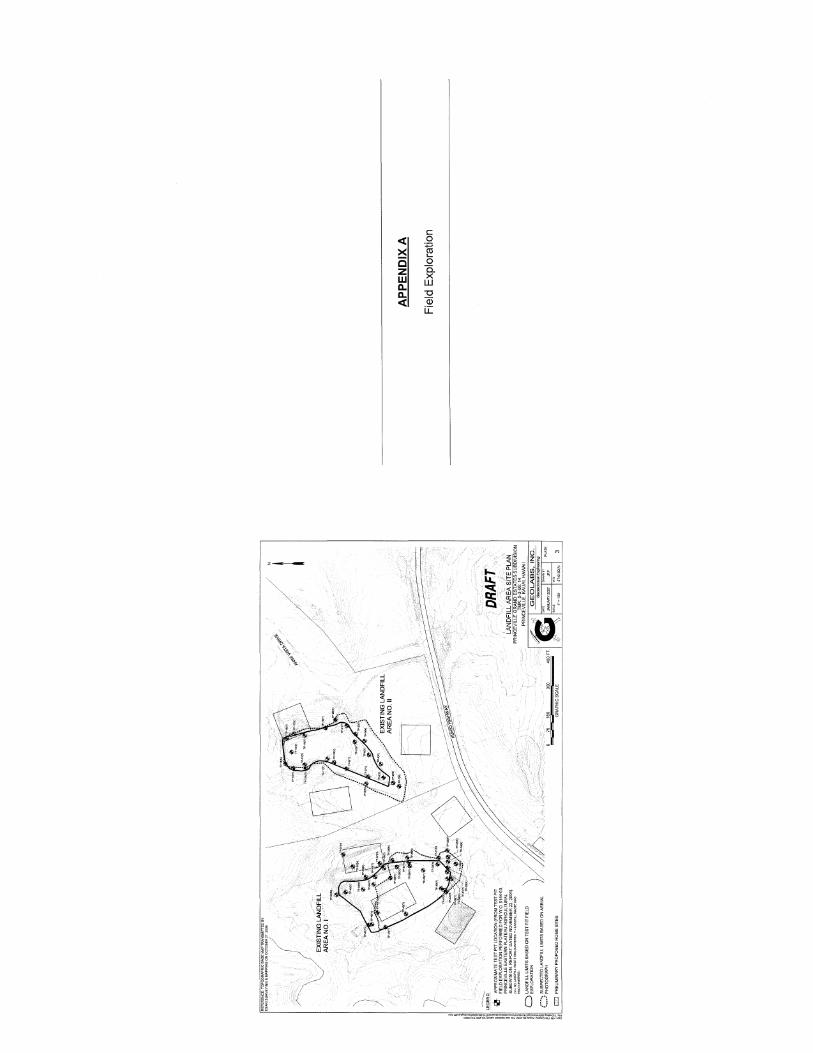
Two closed landfills, identified as Landfill Areas I and lion the Landfill Area Site
Plan, Plate 3, are on the Eastern Plateau approximately Y. mile northeasterly from the
Princeville Airport. The landfills reportedly contain green and construction debris waste
products. We conducted a previous test pit exploration in an effort to delineate the
W.O. 5742-00(A) GEOLABS, INC. Page 7

SECTION 2 - SITE CHARACTERIZATION DRAFT
approximate limits of the closed landfills. Based on our field exploration, the irregular
shaped landfill areas each encompass a footprint of roughly 400 to 600 feet long by
about 200 to 300 feet wide. The results of the test pit exploration are plotted on the
Landfill Area Site Plan, Plate 3. A table summarizing the results of the landfill test pit
exploration is presented in Appendix C. Additional discussion of our findings and
recommendations pertaining to the landfills are presented in Section 3 of this report.
Based on our site reconnaissance, we observed rectangular shaped area of
stockpiled clayey soils approximately 800 feet easterly from the existing Prince Golf
Clubhouse. The stockpile is within Lot 1-0 as approximately shown on the Site Plan,
Plate 2. Based on the available information, the documented stockpile may eventually
reach a volume of about 60,000 cubic yards and is to be used as general fill for future
development projects. The observed soil stockpile presently covers an area measuring
approximately 800 feet by 400 feet as approximately shown on the Site Plan, Plate 2.
The stockpile soils appear to have been dumped and spread without compaction effort
over a period of time.
One of our earlier reports entitled "Soil Engineering Investigation, Proposed
Princeville II Golf Course, Hanalei, Kauai, Hawaii" (W.O. 1142-00) dated July 30, 1982,
noted the potential presence of an old water development tunnel crossing the site to the
north of the existing Prince Golf Course Clubhouse, as approximately shown on the Site
Plan Plate 2.
2.3 Subsurface Conditions
For this current geotechnical field exploration, we explored the general
subsurface conditions at the project site by drilling and sampling 16 test borings,
designated as Boring Nos. 101 through 116, extending to depths of about 21.5 to
81.5 feet below the existing ground surface. The Logs of Borings for Boring Nos. B-101
through B-116 are presented in Appendix A. In addition, our previous field exploration
(conducted in 2004 at the Eastern Plateau) included drilling and sampling of five test
borings, designated as Boring Nos. 1 through 5, extending to depths of about 21.5 to
91.5 feet below the existing ground surface. The Logs of Borings for Boring Nos. B-1
W.O. 5742-00(A) GEOLABS, INC. Page 8
SECTION 2 - SITE CHARACTERIZATION DRAFT
through B-5 are presented in Appendix B. The approximate test boring locations are
shown on the Site Plan, Plate 2.
In addition, during our previous exploration at the Eastern Plateau, the shallow
subsurface conditions and surface limits of existing Landfill Areas I and II were explored
by the excavation and backfilling of test pits. We excavated a total of 58 test pits,
identified as Test Pit Nos. 1 through 58, at Landfill Areas I and II as shown on the
Landfill Area Site Plan, Plate 3. Summary information pertaining to the test pit
exploration is presented in Appendix C.
The borings drilled and sampled for both the previous and current explorations
indicate that the upland plateau region of the project site is generally underlain by stiff to
very stiff residual and saprolitic soils consisting of very moist clayey silts with fine sand
extending to the maximum depth explored of about 91.5 feet below the existing ground
surface. In general, our explorations encountered a surface layer of topsoil, consisting
of brown clayey silts with much organic matter, ranging in thickness from about 0.5 to
1.0 feet bEjlow the existing ground surface. We encountered near-surface silty and
clayey residual soils in the upper 3 to 10 feet of the borings and some scattered zones
of friable, extremely weathered basalt rock throughout the test boring depths. In
addition, the soils were observed to be frequently wet indicating groundwater seepage
and potential perched groundwater conditions. We did not encounter static groundwater
levels in the borings drilled at the project site.
As part of our previous exploration at the site, Test Pit Nos. 1 through 58 were
excavated and backfilled at the existing Landfill Areas I and II located on the upland
plateau region to evaluate the surface limits of the landfills. The test pit locations were
surveyed by a licensed surveyor and plotted on the project base map. In general, stiff to
very stiff silty and clayey capping soils were observed overlying buried construction
material waste and greenwaste. The capping soil cover was observed to range between
about 2 and 7 feet thick depending on location. The depth of soil cover and a tabulation
of the materials encountered by the test pits are presented in Appendix C.
W.O. 5742-00(A) GEOLABS, INC. Page 9

SECTION 2 - SITE CHARACTERIZATION DRAFT
We did not encounter groundwater in the test borings or test pits at the time of
our field exploration. However, it was noted that seams of very wet soils were frequently
observed indicating possible groundwater seepage and potential perched groundwater
conditions. It should be noted that groundwater conditions vary with seasonal rainfall,
time of the year, and other factors. Therefore, transient seepage or perched
groundwater may occur at the site.
In an older exploration, "Soil Engineering Investigation, Proposed Princeville II
Golf Course, Hanalei, Kauai, Hawaii" (W.O. 1142-00) dated July 30, 1982, springs were
observed at the bases of several slopes below the site. These springs indicate that
perched groundwater may be present under the site. This older exploration also noted
the possible presence of an old water development tunnel crossing the site to the north
of the existing Golf Course Clubhouse as approximately shown on the Site Plan,
Plate 2.
Detailed description of our current test boring exploration and the Logs of Borings
(B-101 through B-116) are presented in Appendix A. Detailed description of our
previous test boring exploration conducted at the Eastern Plateau and the associated
Logs of Borings (B-1 through B-5) are presented in Appendix B. Description and
summary information pertaining to our previous test pit field exploration at Landfill Areas
I and II are presented in Appendix C. The results of the laboratory tests performed on
selected soil samples collected at the project site are presented in Appendix D. And
finally, the results of the previous laboratory tests performed on selected soil samples
collected at the Eastern Plateau are presented in Appendix E.
END OF SITE CHARACTERIZATION
W.O. 5742-00(A) GEOLABS, INC. Page 10
DRAFT
SECTION 3.0 - DISCUSSION AND RECOMMENDATIONS
Based on our field exploration conducted for the project, the upland plateau
region of the project site is generally underlain by a thin surface layer of organically rich
topsoil which grades to very moist residual and saprolitic soils consisting of medium stiff
to very stiff clays and silts with fine sand extending to the maximum depth explored of
about 91.5 feet below the ground surface. Our borings encountered varying amounts of
decomposed basalt rock generally consisting of friable sandy and gravelly materials at
various depths. We did not encounter static groundwater levels in the borings at the
time of our field exploration; however, we did encounter frequent wet zones, which
indicate the potential presence of subsurface seepage or perched groundwater
conditions. It should be noted that groundwater levels and seepage vary with seasonal
rainfall, time of the year, and other factors.
Based on the generally competent subsurface conditions encountered at the
upland plateau region of the project site, we anticipate that shallow spread and/or
continuous footings rnay be used to support future house structures that are located
away from the tops of the bluffs at the project site. Residential structures near the tops
of the bluffs may require deep thickened-edge slab footings or drilled piers to provide
adequate support and resistance to sliding.
Some important geotechnical engineering considerations pertaining to the
development of the upland plateau region consist of the following:
• •
General guideline for building setback from the top edge of the bluffs
Landfill slope stability and building setback from landfill limits
Existing area of soil stockpile
Possible old water tunnel alignment
Proposed narrow ridgeline roadway
General recommendations for residential structure foundations
Detailed discussion of these items and our geotechnical recommendations
for design input are presented in the following sections herein.
W.O. 5742-00(A) GEOLABS, INC. Page 11

SECTION 3 - DISCUSSION AND RECOMMENDATIONS DRAFT
We understand that the residential lots will be marketed on an "as-is" basis with
the individual purchaser being responsible for site improvements such as lot grading
and the design of foundations, and assessments for potential geologic hazards such as
rockfall and slope stability issues. In view of this, the individual purchasers should retain
the service of a geotechnical engineer to provide individual consultation and
site-specific geotechnical exploration to develop the necessary construction guidelines
and foundation recommendations.
3.1 Building Set-Back on Bluffs
Based on the conceptual development plan provided, we anticipate that some
residential structures may be constructed along the top edge of the bluffs above
relatively steep slopes generally composed of extremely weathered basalt rock and
saprolitic soils. Although our slope stability analysis indicates that the hillsides may be
generally stable against deep-seated massive type landslide failure, the slopes may
experience recurring shallow-seated failures or thin-skin tears involving the upper few
feet of the near-surface materials, especially on the upper steeper portions of the
slopes. As a result, our opinion is that a minimum building setback guideline of 40 feet
away from the tops of the slopes is necessary to maintain an adequate factor of safety
for future residential structures utilizing shallow foundation systems. "Tops of the
slopes" may be defined as the top part of any slope with an inclination steeper than
about 2H:1V. We recommend conducting additional site-specific geotechnical
engineering exploration to address site-specific building setbacks and various
alternative foundation systems based on the type of structure and loading proposed.
3.2 Existing Landfills
Based on the conceptual development plan provided, it appears that some future
home sites may be planned adjacent to the existing Landfill Areas I and II located on the
eastern upland plateau. We conducted a field investigation consisting of surface
mapping and test pit exploration to evaluate the surface limits of the landfills. The actual
mapped limits generally resemble the suspected landfill limits obtained through
evaluation of aerial photographs with some detail refinement. The actual limits reflect
the mapped extent to which buried green waste and construction debris were
W.O. 5742-00(A) GEOLABS, INC. Page 12
SECTION 3 - DISCUSSION AND RECOMMENDATIONS DRAFT
encountered at the site. The approximate location of the actual landfill limits based on
the results of the field exploration is shown on the Landfill Area Site Plan, Plate 3.
The landfill sites are not considered suitable for the construction of structures and
home sites due to the limited soil cap cover and the potential for substantial ground
settlement. Assuming a valley fill condition, we believe that a minimum 25-foot setback
from the landfill limits may be used as a general guideline for the location of future
buildings. In addition, consideration should be given to the placement of additional fills
at Landfill Area II to meet the required thickness of cover needed for the landfill closure.
Based on our field exploration, we believe that the landfill areas will continue to
experience additional ground settlement induced by the decomposition and settling of
the buried wastes. It has been reported that the buried wastes may extend to depths
greater than about 40 feet in some areas, mainly near the central and northern portions
of the landfill sites. In addition, the buried waste in Landfill Area II appears to have only
limited soil cover with exposed waste observed in some areas at the ground surface.
The capping soil cover encountered on most of this landfill was only a thin veneer of soil
over the waste materials. Because the landfills were constructed at the heads of
pre-existing natural gulch features, the ground settlement should not adversely impact
the stability of the adjacent slopes composed of in-situ saprolitic soils.
However, the landfill perimeter fill slopes generally located upslope of the existing
landfill siltation basins may contain some buried wastes and soft overcast fill materials
that could be problematic for future slope stability. Based on the test pit exploration, the
northwesterly facing fill slope of Landfill Area I was observed to consist of soft,
compressible clayey soils mixed with landfill wastes. Therefore, the existing
northwesterly facing fill slope at Landfill Area I is considered only marginally stable and
may be susceptible to future erosion and slope failure especially since the existing
landfill surface drainage appears to discharge onto a portion of the slope surface.
Based on the field exploration conducted at Landfill Area II, we did not observe
buried waste at the ground surface of the northerly facing fill slope located above the
W.O. 5742-00(A) GEOLABS, INC. Page 13
SECTION 3 - DISCUSSION AND RECOMMENDATIONS DRAFT
existing siltation basin. Furthermore, due to the steep and wet surface condition of the
slope surfaces, we did not excavate test pits on the fill slope at Landfill Area II.
Additional subsurface exploration may be necessary to evaluate the stability of the fill
slope at Landfill Areas I and II.
3.3 Existing Soil Stockpile
Based on our review of a recent aerial photograph and confirmation by our site
reconnaissance, a broad area of surface soil stockpile is centered approximately
800 feet easterly from the existing Prince Golf Clubhouse. The soils consist of light
reddish brown silts and clays. The stockpile soils appear to be spread in level lifts with
minimal compaction effort and are reportedly uncontaminated. The thickness of the
stockpile could not be estimated due to poor surface exposure and vegetation growth.
At the time of our field exploration, the stockpile area was estimated to encompass an
area of about 600 feet long (north to south direction) by about 400 feet wide (east to
west direction) as approximately shown on the Site Plan, Plate 2.
Based on the information provided, we understand the existing soil stockpile may
be used for general fill on future development projects. We recommend the complete
removal of the stockpile to expose the in-situ residual and saprolitic soils prior to
proceeding with road construction and home site development in the affected area.
3.4 Possible Old Water Tunnel
Based on our review of previous in-house soils reports pertaining to the project
site and vicinity, a possible old irrigation water tunnel was previously identified at the
project site. The. approximate location is north of the existing Prince Golf Course
Clubhouse as shown on the Site Plan, Plate 2. The actual presence of the water tunnel
should be verified by a review of available records or by field exploration such as test pit
excavation before proceeding with site development in the vicinity. If the tunnel is found
to exist, additional geotechnical engineering consultation is recommended and
exploration is required to explore the existing conditions and provide recommendations
for tunnel closure or incorporation into the planned development scheme.
W.O. 5742-00(A) GEOLABS, INC. Page 14
SECTION 3 - DISCUSSION AND RECOMMENDATIONS DRAFT
3.5 Proposed Ridgeline Roadway
Based on the available conceptual development plan, we understand that a new
subdivision roadway is planned along and crossing the top of a relatively narrow bluff
ridgeline. A portion of the proposed new roadway is between the proposed Lot Nos. 1-0
and 4-0 skirts and traverses a narrow ridgeline with steep side slopes on both sides of
the ridge. We drilled Boring No. 2 of our previous exploration at this narrow ridgeline
location as shown on the Site Plan, Plate 2. We anticipate that the existing side slope
topography may pose significant constraints for the construction of a traditional concrete
retaining wall system to support the roadway. Therefore, we envision that site grading
consisting of earth cuts may be performed to increase the width of the ridgeline, or to
develop a stable bench, for the construction of the roadway prism. If the desired ridge or
bench width cannot be achieved by site grading alone, we believe that a retaining wall
system consisting of Mechanical Stabilized Earth (MSE) walls may be utilized.
3.6 Foundations
Based on the subsurface conditions encountered at the project site, we anticipate
that shallow spread and/or continuous footings may be used to support the new
structures located away from the tops of bluffs at the project site. Residential structures
planned near the tops of the bluffs may require special foundations such as deep
thickened-edge slab footings or drilled piers. As a general guide, an allowable bearing
pressure of up to 2,000 pounds per square foot (psf) may be used for the design of
footings bearing on the compacted fill or stiff on-site clayey silt and/or silty clay
materials. This bearing value is for dead-plus-live loads and may be increased by
one-third (1/3) for transient loads, such as those caused by wind or seismic forces.
In general, footings should be embedded a minimum of 18 inches below the
lowest adjacent exterior grade.
Foundations next to other foundations, utility trenches, or easements should be
embedded below a 45-degree imaginary plane extending upward from the bottom edge
of the utility trench, or the footings should extend as deep as the inverts of the utility
lines. This requirement is necessary to avoid surcharging adjacent below-grade
W.O. 5742-00(A) GEOLABS, INC. Page 15

SECTION 3 - DISCUSSION AND RECOMMENDATIONS DRAFT
structures with additional structural loads and to reduce the potential for appreciable
foundation settlement.
In general, the subgrade soils at the bottom of footing excavations should be
moisture-conditioned to above the optimum moisture and recompacted to a minimum of
90 percent relative compaction prior to the placement of reinforcing steel or concrete.
Relative compaction refers to the in-place dry density of soil expressed as a percentage
of the maximum dry density of the same soil established in accordance with
ASTM D 1557. Optimum moisture is the water content (percentage by dry weight)
corresponding to the maximum dry density.
Soft and/or loose materials encountered at the bottom of footing excavations
should be over-excavated until dense and/or stiff materials are exposed in the footing
excavation. The over-excavation should be backfilled with select granular fill materials
moisture-conditioned to above the optimum moisture content and compacted to a
minimum of 90 percent relative compaction. Alternatively, the bottom of the footing may
extend down to bear directly on the underlying competent material.
Lateral loads acting on the structure may be resisted by friction developed
between the bottom of the foundation and the bearing soil and by passive earth
pressure acting against the near-vertical faces of the foundation system. A coefficient of
friction of 0.35 may be used for footings bearing on the stiff on-site clayey silt and/or
silty clay materials. Resistance due to passive earth pressure may be estimated using
an equivalent fluid pressure of 300 pounds per square foot per foot of depth (pcf)
assuming that the soils around the footings are well compacted. The passive resistance
in the upper 12 inches of the soil should be neglected unless covered by pavements or
slabs.
3.7 Siabs-On-Grade
We anticipate that concrete slabs-on-grade will be used. The near-surface soils
encountered in our borings generally consist of silty clays, which exhibit a slight
expansion potential when subjected to moisture fluctuations. Therefore, to reduce the
W.O. 5742-00(A) GEOLABS, INC. Page 16
SECTION 3 - DISCUSSION AND RECOMMENDATIONS DRAFT
potential for structural distress to the lightly loaded slabs, we recommend providing a
minimum of 6 inches of non-expansive select granular fill material below the concrete
slab.
The subgrades for concrete slabs-on-grades should be scarified to a depth of at
least 8 inches, moisture-conditioned to at least 2 percent above the optimum moisture,
and compacted to no less than 90 percent relative compaction. Relative compaction
refers to the in-place dry density of soil expressed as a percentage of the maximum dry
density of the same soil determined in accordance with ASTM D 1557. Optimum
moisture is the water content (percentage by dry weight) corresponding to the maximum
dry density.
The non-expansive select granular fill recommended below the floor slabs should
consist of imported granular material such as crushed coral, basaltic gravel or cinder
sand. The material should be well graded from coarse to fine with no particles larger
than 3 inches in largest dimension. The material should have a laboratory California
Bearing Ratio (CBR) value of 20 or higher, and a swell potential of 1 percent or less
when tested in accordance with ASTM D 1883. The material also should contain
between 10 and 30 percent particles passing the No. 200 sieve. The select granular fill
materials should be moisture-conditioned to above the optimum moisture content and
compacted to at least 90 percent relative compaction. The slab subgrade should be
kept moist until covered by the select granular fill.
For the interior building slabs (which will not be subject to vehicular traffic), we
recommend providing a minimum 4-inch thick layer of cushion fill over the 6-inch select
granular fill materials for uniform support. The cushion fill should consist of open-graded
gravel (ASTM C 33, No. 67 gradation) and would also serve as a capillary moisture
break.
To reduce the potential for excessive moisture infiltration and subsequent
damage to floor coverings, an impervious moisture barrier is recommended on top of
W.O. 5742-00(A) GEOLABS, INC. Page 17

SECTION 3 - DISCUSSION AND RECOMMENDATIONS DRAFT
the gravel cushion layer. Flexible floor coverings should be considered above the floor
slab since they can better mask minor slab cracking.
In addition, we envision that exterior concrete walkways and exterior flatwork will
likely be required. In general, we recommend providing a minimum 4-inch thick cushion
layer of base course below the exterior concrete slab. To reduce the potential for
substantial shrinkage cracks in the slabs, crack control joints should be provided at
intervals equal to the width of the walkways (or slabs) with expansion joints at right
angle intersections.
3.8 Retaining Structures
Some retaining structures, such as walls for roadway support and drainage
structure headwalls, may be required for construction. Therefore, the following general
guidelines are provided and may be used for the design of low retaining structures.
3.8.1 Retaining Structure Foundations
In general, we believe that retaining structure foundations may be designed in
accordance with the recommendations and parameters presented in the
"Foundations" section herein. However, the retaining structure footings should have
a minimum width of 18 inches. In addition, wall foundations located on relatively flat
areas should be embedded a minimum depth of 24 inches below the lowest
adjacent finished grade for retaining structures of 5 feet high or greater. Footing
embedment depth of 18 inches may be used for low retaining structures of less
than 5 feet high.
For sloping ground conditions, the footing should extend deeper to obtain a
minimum 6-foot setback distance measured horizontally from the outside edge of
the footing to the face of the slope. Wall footings oriented parallel to the direction of
the slope should be constructed in stepped footings.
3.8.2 Static Lateral Earth Pressures
In general, retaining structures should be designed to resist the lateral earth
pressures due to the adjacent soils and surcharge effects. The recommended
W.O. 5742-00(A) GEOLABS, INC. Page 18
SECTION 3 - DISCUSSION AND RECOMMENDATIONS DRAFT
lateral earth pressures for design of retaining structures, expressed in equivalent
fluid pressures of pounds per square foot per foot of depth (pcf), are presented in
the following table. These lateral earth pressures do not include hydrostatic
pressures that might be caused by groundwater trapped behind the structures.
LATERAL EARTH PRESSURES FOR DESIGN OF RETAINING STRUCTURES
Backfill Earth Pressure Condition Com~onent Active At-Rest
(Pcf) (pd)
Horizontal 40 60 Level Backfill
Vertical None None
Maximum Horizontal 58 76
2H:1V Sloping Vertical 30 38 Backfill
The values provided above assume that granular soils less than 3 inches in
maximum dimension will be used to backfill directly behind the retaining structures.
The zone of granular soils with a maximum particle size of 3 inches should extend a
minimum of 3 feet laterally behind the retaining walls. Backfill beyond this 3-foot
zone may consist of compacted on-site soils.
We assume that the backfill behind retaining structures will be compacted to
between 90 and 95 percent relative compaction. Over-compaction of the retaining
structure backfill should be avoided. In general, an active condition may be used for
gravity retaining walls and retaining structures that are free to deflect laterally by as
much as 0.5 percent of the wall height. If the tops of the structures are not free to
deflect beyond this degree, or are restrained, the retaining structures should be
designed for the at-rest condition.
Surcharge stresses due to areal surcharges, line loads, and point loads within a
horizontal distance equal to the depth of the retaining structures should be
W.O. 5742-00(A) GEOLABS, INC. Page 19
SECTION 3 - DISCUSSION AND RECOMMENDATIONS DRAFT
considered in the design. For uniform surcharge stresses imposed on the loaded
side of the structure, a rectangular distribution with uniform pressure equal to
33 percent of the vertical surcharge pressure acting on the entire height of the
structure, which is free to deflect (cantilever), may be used in design. For retaining
structures that are restrained, a rectangular distribution equal to 50 percent of the
vertical surcharge pressure acting over the entire height of the structure may be
used for design. Additional analyses during design may be needed to evaluate the
surcharge effects of point loads and line loads.
3.8.3 Retaining Structure Drainage
In general, retaining structures should be well drained to reduce the build-up of
hydrostatic pressures. A typical drainage system would consist of a 12-inch wide
zone of permeable material, such as No. 3B Fine gravel (ASTM C 33, No. 67
gradation), placed directly around a perforated pipe (perforations down) at the base
of the retaining wall. The perforated pipe should discharge to an appropriate outlet
or weepholes.
As an alternative, a prefabricated drainage product, such as MiraDrain or
EnkaDrain, may be used instead of the permeable drainage material. The
prefabricated drainage product should also be hydraulically connected to a
perforated pipe at the base of the retaining wall. Unless covered by concrete or
asphaltic concrete, the upper 12 inches of backfill should consist of relatively
impervious materials, such as the on-site clayey soils, to reduce the potential for
significant water infiltration behind the walls.
3.9 Site Grading
In general, we anticipate that cuts and fills of about 10 to 20 feet or less relative
to the existing ground surface may be required in order to achieve the finished grades
for the proposed project. The following grading items are addressed in the succeeding
subsections:
w.O. 5742-00(A) GEOLABS, INC. Page 20
SECTION 3 - DISCUSSION AND RECOMMENDATIONS
1. 2. 3. 4. 5.
Site Preparation Fills and Backfills
DRAFT
Fill Placement and Compaction Requirements Cut and Fill Slopes Excavation
Site grading operations should be observed by a Geolabs representative to
evaluate whether undesirable materials are encountered during the excavation process
and to confirm whether the exposed soil/rock conditions are similar to those
encountered in our field exploration.
3.9.1 Site Preparation
At the on-set of earthwork, areas within the contract grading limits should be
cleared and grubbed thoroughly. Vegetation, debris, deleterious material, and other
unsuitable materials should be removed and disposed of properly off-site to reduce
the potential for contamination of the excavated materials.
After clearing and grubbing, finished subgrades in cut areas and areas designated
to receive fills should be scarified to a minimum depth of 8 inches,
moisture-conditioned to above the optimum moisture content, and compacted to a
minimum of 85 percent relative compaction. Relative compaction refers to the
in-place dry density of soil expressed as a percentage of the maximum dry density
of the same soil established in accordance with AASHTO T-180 (ASTM D 1557).
Optimum moisture is the water content (percentage by dry weight) corresponding to
the maximum dry density.
Yielding areas and soft/loose areas disclosed during clearing and scarification
operations should be over-excavated and backfilled with well-compacted fill
materials.
3.9.2 Fills and Backfills
In general, the excavated on-site materials may be re-used as a source of general
fill material provided that the materials are free of vegetation, deleterious materials,
and clay lumps and rock fragments greater than 3 inches in maximum dimension.
w.O. 5742-00(A) GEOLABS, INC. Page 21

SECTION 3 - DISCUSSION AND RECOMMENDATIONS DRAFT
Imported fill materials, if required, should consist of non-expansive select granular
material, such as crushed coralline or basaltic materials. The materials should be
well graded from coarse to fine with no particles larger than 3 inches in largest
dimension and should contain between 10 and 30 percent particles passing the
No. 200 sieve. The materials should have a laboratory CBR value of 20 or more
and should have a maximum swell of 1 percent or less. Imported fill materials
should be tested for conformance with these recommendations prior to delivery to
the project site for the intended use.
3.9.3 Fill Placement and Compaction Requirements
Fill materials should be placed in level lifts not exceeding 8 inches in loose
thickness, moisture-conditioned to above the optimum moisture, and compacted to
at least 85 percent relative compaction. The compaction requirement should be
increased to 90 percent relative compaction for fills placed within 3 feet under the
pavements. Relative compaction refers to the in-place dry density of soil expressed
as a percentage of the maximum dry density of the same soil established in
accordance with AASHTO T-180 (ASTM 01557). Optimum moisture is the water
content (percentage by dry weight) corresponding to the maximum dry density.
Compaction should be accomplished using sheepsfoot rollers, vibratory rollers, or
other types of acceptable compaction equipment.
The filling operations should start at the lowest point and continue up in level
horizontal compacted layers in accordance with the above fill placement
recommendations. Fill slopes should be constructed by overfilling and cutting back
to the design slope ratio to obtain a well-compacted slope face. Surface water
should be diverted away from the tops of slopes, and slope planting should be
provided as soon as possible to reduce the potential for significant erosion of the
finished slopes.
It should be noted that the project site is in an area with significant rainfall
throughout the year. Therefore, earthwork operations in these high rainfall areas
may be difficult and will result in slower than normal earthwork operations.
W.O. 5742-00(A) GEOLABS, INC. Page 22
SECTION 3 - DISCUSSION AND RECOMMENDATIONS DRAFT
3.9.4 Cut and Fill Slopes
We envision that cut slopes at the site will generally expose the stiff to very stiff silty
clays and clayey silts encountered in our borings. In general, cut slopes and
permanent fill slopes may be designed with a slope inclination of 2H:1V or flatter.
Fills placed on slopes steeper than 5H:1V should be keyed and benched into the
existing slope to provide stability of the new fill against sliding.
Construction of earth berms, interceptor ditches, and the use of geotextile fabrics
over the fill slope face should be considered to reduce the potential for significant
erosion, thus enhancing the long-term stability of the fill slopes. Appropriate slope
planting or other erosion control measures to reduce the potential for significant
erosion of the exposed slopes (including a permanent irrigation system) should be
implemented as soon as possible after the finished slope faces are completed.
3.9.5 Excavation
Based on our field exploration, the project site is generally underlain by medium stiff
to very stiff silty clay and clayey silt materials. We anticipate that the near-surface
materials may be excavated with normal heavy excavation equipment, such as
excavating with a backhoe excavator. However, it should be noted that occasional
weathered and decomposed rock materials were locally encountered in our
borings. Therefore, it should be noted that the contractors may encounter some
difficult excavation conditions in localized areas.
The above discussions regarding the excavation of the materials are based on our
visual observation of the existing site conditions and field data from the borings
drilled at the site. Contractors proposing to bid on this project should be
encouraged to examine the site conditions and the boring data to make their own
interpretation.
3.10 Pavement Design
We understand that flexible pavements may be used for the subdivision
roadways planned. In general, we antiCipate that the vehicle loading for the proposed
W.O. 5742-00(A) GEOLABS, INC. Page 23

SECTION 3 - DISCUSSION AND RECOMMENDATIONS DRAFT
subdivision roadways would primarily consist of passenger vehicles with some light
trucks only. However, consideration may be given to the anticipated heavy construction
traffic that may be experienced as the home sites are developed over a period of time.
Therefore, we have assumed generally light to medium traffic loading conditions for
pavement design purposes.
We have assumed that the pavement subgrade soils will be similar to the silty
clay and clayey silt soils encountered during our field exploration with a CBR value of
about 10. On this basis, we recommend using the following preliminary pavement
designs for this project.
Flexible Pavement Section
2.0-lnch Asphaltic Concrete 6.0-lnch Aggregate Base Course (95 Percent Relative Compaction) 6.0-lnch Aggregate Subbase Course (95 Percent Relative Compaction)
14.0-lnch Total Pavement Thickness on Moist Compacted Subgrade
The subgrade soils under the pavement areas should be scarified to a minimum
depth of 8 inches, moisture-conditioned to above the optimum moisture, and compacted
to at least 95 percent relative compaction. CBR tests and/or field observations should
be performed on the actual subgrade soils during construction to confirm that the above
design section is adequate. The aggregate base and subbase courses should consist of
crushed basaltic aggregate compacted to a minimum of 95 percent relative compaction.
In general, paved areas should be sloped, and drainage gradients should be
maintained to carry surface water off the pavements. Surface water ponding should not
be allowed on-site during or after construction. Where concrete curbs are used to
isolate landscaping in or adjacent to the pavement areas, we recommend extending the
curbs a minimum of 2 inches into the subgrade soil to reduce the potential for migration
of excessive landscape water into the pavement section.
Due to the extremely humid conditions in the Princeville area, our opinion is that
there is a potential for accumulation of water in pavement subgrades, even with the
implementation of the recommendations presented above. Such accumulation of water
W.O. 5742-00(A) GEOLABS, INC. Page 24
SECTION 3 - DISCUSSION AND RECOMMENDATIONS DRAFT
in the subgrades can result in pumping of the pavement prism and lead to decreased
service life for the pavements. Therefore, we recommend giving consideration to the
installation of subdrains at the bottom of the base course in the pavement section.
Prefabricated drainage materials, such as MiraDrain™, could be placed along the sides
of the road prism, providing an easily installed subdrain system. The subdrains should
be designed and installed to allow for drainage outside of the road prism by either
discharging to catch basins or to daylight outside of the prism area.
3.11 Underground Utility Lines
We envision that new underground utility lines will be required for development.
We anticipate that most of the trenches for utilities will be excavated in the on-site silty
and clayey soils.
In general, granular bedding consisting of 6 inches of No. 3B Fine gravel
(ASTM C 33, No. 67 gradation) is recommended for support below the pipes.
Free-draining granular materials, such as No. 3B Fine gravel (ASTM C 33, No. 67
gradation), should also be used for the initial trench backfill up to about 12 inches above
the pipes. It is critical to use this free-draining material to reduce the potential for
formation of voids below the haunches of the pipes and to provide adequate support for
the sides of the pipes. Improper backfill material around the pipes and improper
placement of the backfill could result in backfill settlement and pipe damage.
The upper portion of the trench backfill from a level of 12 inches above the pipes
to the top of the subgrade or finished grade should consist of granular materials
generally less than 6 inches in maximum particle size. The backfill material should be
moisture-conditioned to above the optimum moisture content, placed in maximum
8-inch level loose lifts, and mechanically compacted to at least 90 percent relative
compaction. Where trenches will be in paved areas, the upper 3 feet of the trench
backfill below the pavement grade should be compacted to no less than 95 percent
relative compaction.
W.O. 5742-00(A) GEOLABS, INC. Page 25

SECTION 3 - DISCUSSION AND RECOMMENDATIONS DRAFT
3.12 Drainage
The finished grades outside the houses and other structures should be sloped to
shed water away from the foundations and slabs and to reduce the potential for
ponding. It is also advised to install gutter systems around the buildings and to divert the
discharge away from the foundation and slab areas. Excessive landscape watering near
the foundations and slabs should also be avoided. Planters next to foundations
(within 3 feet) should be avoided or have concrete bottoms and drains to reduce the
potential for excessive water infiltration into the subsurface.
The foundation excavations should be properly backfilled against the walls or
slab edges immediately after setting of the concrete to reduce potential for excessive
water infiltration into the subsurface. In addition, drainage swales should be provided as
soon as possible and should be maintained to drain surface water runoff away from the
foundations and slabs.
Previous experience in the Princeville area indicates that, due to the very humid
climate, there is a potential for seepage to occur through interior building retaining walls
for basements and half basements. Therefore, careful attention should be given to the
design and installation of waterproofing and subdrains for interior retaining walls.
Subdrains should be installed at depths lower than the interior floor slabs and as close
to the outside edge of the wall footings as possible without undermining the footing.
3.13 Design Review
Preliminary and final drawings and specifications for the proposed project should
be forwarded to Geolabs for review and written comments prior to bid advertisement.
This review is necessary to evaluate general conformance of the plans and
specifications with the intent of the foundation and earthwork recommendations
provided herein. If this review is not made, Geolabs cannot be responsible for
misinterpretation of our recommendations.
W.O. 5742-00(A) GEOLABS, INC. Page 26
SECTION 3 - DISCUSSION AND RECOMMENDATIONS DRAFT
3.14 Construction Monitoring
Geolabs should be retained to provide geotechnical engineering services during
construction of the proposed project. The critical items of construction monitoring that
require "Special Inspection" include observation of the subgrade preparation, fill
placement and compaction, and foundation construction. This is to observe compliance
with the design concepts, specifications, or recommendations and to expedite
suggestions for design changes that may be required in the event that subsurface
conditions differ from those anticipated at the time this report was prepared. The
recommendations provided herein are contingent upon such observations.
If the actual exposed subsurface conditions encountered during construction are
different from those assumed or considered in this report, then appropriate design
modifications should be made.
END OF DISCUSSION AND RECOMMENDATIONS
W.O. 5742-00(A) GEOLABS, INC. Page 27

DRAFT ----
SECTION 4.0 - LIMITATIONS
The analyses and recommendations submitted herein are based, in part, upon
information obtained from literature research and field exploration consisting of site
reconnaissance, drilled borings, and test pit excavations. Variations of subsurface
conditions between and beyond the observations and test locations may occur, and the
nature and extent of these variations may not become evident until construction is
underway. If variations then appear evident, it will be necessary to re-evaluate the
recommendations provided in this report.
The field boring locations indicated herein are approximate, having been taped
from field reference stakes and existing features shown on the aerial topographic survey
maps transmitted by Esaki Surveying and Mapping Inc. on January 20, 2004 and
October 27,2006. Boring elevations were estimated based on interpolation between the
topographic contour lines shown on the same plan. The physical locations and
elevations of the borings should be considered accurate only to the degree implied by
the methods used. Esaki Surveying and Mapping Inc. surveyed the locations of the test
pits excavated at the existing Landfill Areas I and II and the test pit locations were
included on the aerial topographic base map transmitted to our office by same party on
January 20, 2004.
The stratification lines shown on the graphic representations of the borings depict
the approximate boundaries between soil/rock types and, as such, may denote a
gradual transition. Water level data from the borings and test pits were measured at the
times shown on the graphic representations and/or presented in the text herein. We
encountered groundwater in some of the borings and test pits at the time of our field
exploration. These data have been reviewed and interpretations made to formulate this
report. However, it must be noted that significant fluctuation may occur due to variation
in rainfall, temperature, tides, storm surges, and other factors.
This report has been prepared for the exclusive use of Princeville Prince Golf
Course, LLC .for specific application to the design of the proposed Princeville Grand
W.O. 5742-00(A) GEOLABS, INC. Page 28
SECTION 4 - LIMITATIONS DRAFT
Estates Subdivision project in accordance with generally accepted geotechnical
engineering principles and practices. No warranty is expressed or implied.
This report has been prepared solely for the purpose of assisting the engineer in
the preparation of the design drawings related to the development of the project.
Therefore, this report may not contain sufficient data, or the proper information, to serve
as the basis for preparation of construction cost estimates. A contractor wishing to bid
on this project is urged to retain a competent geotechnical engineer to assist in the
interpretation of this report and/or in the performance of additional site-specific
exploration for bid estimating purposes.
The owner/client should be aware that unanticipated subsurface conditions are
commonly encountered. Unforeseen subsurface conditions, such as perched
groundwater, soft deposits, hard layers, or cavities, may occur in localized areas and
may require additional probing or corrections in the field (which may result in
construction delays) to attain a properly constructed project. Therefore, a sufficient
contingency fund is recommended to accommodate these possible extra costs.
This geotechnical exploration conducted at the project site was not intended to
investigate the potential presence of hazardous materials existing at the site. The
equipment, techniques, and personnel used to conduct a geo-environmental exploration
differ substantially from those applied in geotechnical engineering.
END OF LIMITATIONS
W.O. 5742-00(A) GEOLABS, INC. Page 29

DRAFT
CLOSURE
The following plates and appendices are attached and complete this report:
Plate 1
Plate 2
Plate 3
Appendix A
Plate A
Plates A-1 thru A-16
Appendix B
Plate B
Plates B-1 thru B-5
AppendixC
Plates C-1 thru C-3
Appendix D
Plates D-1 thru D-24
Appendix E
Plates E-1 thru E-9
-00000000000000000000-
Respectfully submitted,
GEOLABS, INC.
DRAFT
By __ ~~~~~ __ -=~ Clayton S. Mimura, P.E.
President
CSM:DEF/sc:mj~ [h:\5700 Series\5742-00(A).sc1-pg.34]
w.o. 5742-00(A) GEOLABS, INC.
Project Location Map
Site Plan
Landfill Area Site Plan
Field Exploration
Boring Log Legend
Logs of Borings
Previous Field Exploration
Log Legend
Logs of Borings
Previous Test Pit Exploration
Summary of Test Pit Information
Laboratory Testing
Laboratory Test Data
Previous Laboratory Testing
Laboratory Test Data
Page 30
PLATES

CJ elf.
N
PROJECT LOCATION MAP PRINCEVILLE GRAND ESTATES SUBDIVISION
TMK: 5-3-06: 14 PRINCEVILLE, KAUAI, HAWAII
ABS,I 2000 1000 0 2000 FT. ~ • I GEOL I it P"'"""""""IJ GeotechnICal Englnerntng
o GRAPHIC SCALE DATE DRAVVN BY • P~~ Ii: JANUARY 2007 JRP
~" REFERENCE: MAP CREATED WITH TOPOI®C2001 NATIONAL SCALE W.O ~ ~ GEOGRAPHIC (WWW.NATlONALGEOGRAPHIC.COMlTOPO). 1" = 2,000' 5742-00(A) 1 I
« >< 2i z W 0..
~

DRAFT
APPENDIX A
Field Exploration
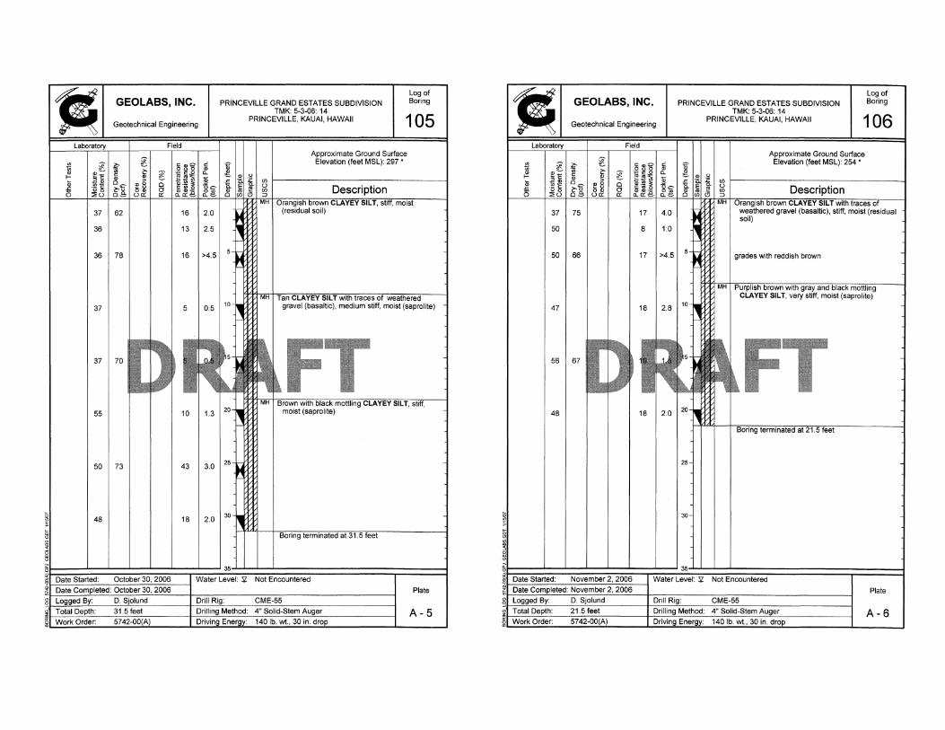
We explored the subsurface conditions at the project by drilling and sampling sixteen borings designated as Boring Nos. B-101 through B-116. The borings were advanced to depths ranging from approximately 21.5 to 81.5 feet below the existing ground surface. The borings were drilled using a truck-mounted drill rig equipped with continuous-flight and hollow-stem auger tools. The approximate boring locations are shown on the Site Plan, Plate 2.
The materials encountered in the borings were classified by visual and textural examination in the field by our geologist, who monitored the drilling operations on a near-continuous basis. Soils were classified in general conformance with the Unified Soil Classification System, as shown on Plate A. Graphic representations of the materials encountered are presented on the Logs of Borings, Plates A-1 through A-16.
Relatively "undisturbed" soil samples were obtained from the borings in general accordance with ASTM D 3550, Ring-Lined Barrel Sampling of Soils, by driving a 3-inch OD Modified California sampler with a 140-pound hammer falling 30 inches. In addition, some samples were obtained from the drilled borings in general accordance with ASTM D 1586, Penetration Test and Split-Barrel Sampling of Soils, by driving a 2-inch OD standard penetration sampler using the same hammer and drop. The blow counts needed to drive the sampler the second and third 6 inches of an 18-inch drive are shown as the "Penetration Resistance" on the Logs of Borings at the appropriate sample depths.
Ih:15700 Series\5742-00(A).sc1-pg.37]
W.O. 5742-00(A) GEOLABS, INC. JANUARY 2007 Page A-1
~
! I I
• GEOLABS, INC. Log Legend
Geotechnical Engineering
UNIFIED SOIL CLASSIFICATION SYSTEM (USCS)
MAJOR DIVISIONS
GRAVELS
CLEAN GRAVELS
LESS THAN 5% FINES COARSE
GRAINED SOILS M~'}?c!~~O% I GRA~~~~tITH
MORE THAN 50% OF MATERIAL
RETAINED ON NO. 200 SIEVE
FINEGRAINED
SOILS
50% OR MORE OF MATERIAL PASSING
THROUGH NO. 200 SIEVE
FRACTION RETAINED ON NO. 4 SIEVE
SANDS
SILTS AND
CLAYS
UQUIDUMrr 50 QR MORE
HIGHLY ORGANIC SOILS
~
I:"!!I (2-INCH) 0.0. STANDARD PENETRATION TEST
8 (3-INCH) 0.0. MODIFIED CALIFORNIA SAMPLE
lSI SHELBY TUBE SAMPLE
~ GRAB SAMPLE
o CORlE SAMPLE
USCS
LL
PI
TV
PEN
UC
Yl
TYPICAL DESCRIPTIONS
WELL-GRADED GRAVELS. GRAVEL-SAND MIXTURES. UTILE OR NO FINES
POORLY-GRADED GRAvELS. GRAVEL-SAND MIXTURES. UTILE OR NO FINES
SILTY GRAVELS, GRAVEL-SAND-SIL T MIXTURES
CLAYEY GRAVELS. GRAVEL-SAND-CLAY MIXTURES
WELL-GRADED SANDS. GRAVELLY SANDS. LITTLE OR NO FINES
POORLY-GRADED SANDS, GRAVELLY SANDS. LITTLE OR NO FINES
INORGANIC SILT. MICACEOUS OR DIATOMACEOUS FINE SAND OR SILTY SOILS
INORGANIC CLAYS OF HIGH PLASTICITY
ORGANIC CLAYS OF MEDIUM TO HIGH PLASTICrrv. ORGANIC SILTS
PEAT, HUMUS, SWNA,P SOILS WITH HIGH ORGANIC CONTENTS
LIQUID LIMIT
PLASTICITY INDEX
TORVANE SHEAR (lsi)
POCKET PENETROMETER (lsi)
UNCONFINED COMPRESSION (psi)
WATER LEVEL OBSERVED IN BORING Plate
A glL-____________________________________________________________________________________ J

GEOLABS, INC.
36 7
47 I 76 14
44 8
53
61 7
Log of Boring PRINCEVILLE GRAND ESTATES SUBDIVISION
TMK: 5-3-06: 14 PRINCEVILLE, KAUAI, HAWAII 101
Approximate Ground Surface Elevation (feet MSL): 295 •
traces of moderately to highly weathered gravel (basaltic), medium stiff to stiff, moist (saprolite)
FT • Elevations estimated from
Topographic Map provided by Esaki Surverying & Mapping on October 27, 2008.
Plate
A -1
GEOLABS, INC.
~
41 8
41 I 83 15
33 4
71
50 11
45 I 77 26
54 15
Log 01 BOring PRINCEVILLE GRAND ESTATES SUBDIVISION
TMK: 5-3-06: 14 PRINCEVILLE, KAUAI, HAWAII 102
Approximate Ground Surface Elevation (feet MSL): 325 •
FT
Plate
A-2

GEOLABS, INC. PRINCEVILLE GRAND ESTATES SUBDIVISION TMK: 5-3-06: 14
PRINCEVILLE, KAUAI, HAWAII
Log of Boring
103
Approximate Ground Surface
35
34 I 88
14
9
16
39 1 1 1 1 7 11.3 1,um 1
Elevation (feet MSL): 317'
~\:l; I " I " • I •• il'"W. FT 43 I I I I 17 I I .u-.vJ.1
52 I 68 25
52 18
Water Level: Yi/. Not Encountered
Plate
A-3
1
i
~
! ~
GEOLABS, INC.
Geotechnical Engineering
40
43
45 I 76
I 56 I I
I 48
7
15
I I 9
1531 I I I 9
54 I 70 24
57 6
PRINCEVILLE GRAND ESTATES SUBDIVISION TMK: 5-3-06: 14
Log of Boring
PRINCEVILLE, KAUAI, HAWAII 104
Approximate Ground Surface Elevation (feet MSL): 310'
Plate
A-4
GEOLABS, INC.
36 13
36 I 78 16
37 5
37
55 10
50 I 73 43
48 18
Log of Boring PRINCEVILLE GRAND ESTATES SUBDIVISION
TMK: 5-3-06: 14 PRINCEVILLE, KAUAI, HAWAII 105
Approximate Ground Surface Elevation (feet MSL): 297 *
Plate
A-5
• GEOlABS, INC.
Geotechnical Engineering
~ ~ ~ ~ ~~g "
,,~ <IJ ~ e ~ ~.!~ t- ~"E
" !!l Ii is 0'li' I!'B ° ~·i~ 5
°06 ~.s 00) 0
:iiU ua: a: a.. a:: 8
37 75 17
50 8
50 I 66 17
47 18
56 I 67
48 18
PRINCEVILLE GRAND ESTATES SUBDIVISION TMK: 5-3-06: 14
Log of Boring
PRINCEVILLE, KAUAI, HAWAII 106
Approximate Ground Surface Elevation (feet MSL): 254 *
FT
Plate
A-6

GEOLABS, INC.
32 13
36 I 80 15
43 6
61
36 4
43 I 70 7
52 7
PRINCEVILLE GRAND ESTATES SUBDIVISION TMK: 5-3-06: 14
Log of Boring
PRINCEVILLE, KAUAI, HAWAII 107
Approximate Ground Surface Elevation (feet MSL): 278 •
grades to orang ish brown with red mottling
Plate
A-7
GEOLABS, INC.
38
54
36 I 90
47
40
53
55 I 63
52
10
16
13
7
20
19
PRINCEVILLE GRAND ESTATES SUBDIVISION TMK: 5-3-06: 14
Log of Boring
PRINCEVILLE, KAUAI, HAWAII 108
Approximate Ground Surface Elevation (feet MSL): 244 •
Plate
A-a

GEOLABS, INC.
~ I!!::::
i; ii 5 00
::i:U
46
37 9
35 91 17
44 16
45
52 13
55 I 70 25
53 11
PRINCEVILLE GRAND ESTATES SUBDIVISION TMK: 5-3-06: 14
Log of Boring
PRINCEVILLE, KAUAI, HAWAII 109
Approximate Ground Surface Elevation (feet MSL): 242 •
Plate
A-9
j g
GEOLABS, INC.
Geotechnical Engineering
41
33
36 I 80
38
32
45 I 75
54
52
18
20
13
19
10
9
PRINCEVILLE GRAND ESTATES SUBDIVISION TMK: 5-3-06: 14
PRINCEVILLE, KAUAI, HAWAII
Log of Boring
110
Approximate Ground Surface Elevation (feet MSL): 237 •
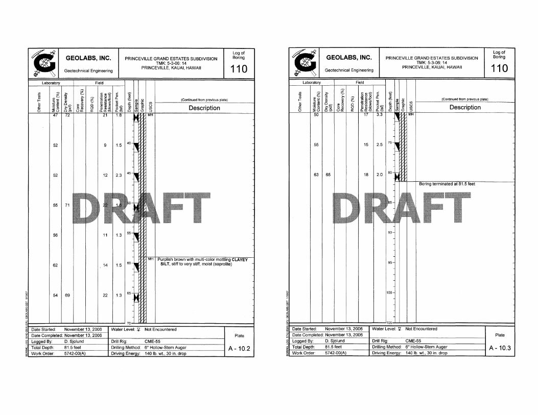
grades with black mottling
Plate
A-10.1
GEOLABS, INC.
52 9
52 12
55
56 11
62 14
54 I 69 22
PRINCEVILLE GRAND ESTATES SUBDIVISION TMK: 5-3-06: 14
PRINCEVILLE, KAUAI, HAWAII
FT
Water Level: '5i/. Not Encountered
Log of Boring
110
Plate
A- 10.2
GEOLABS, INC.
Geotechnical Engineering
PRINCEVILLE GRAND ESTATES SUBDIVISION TMK: 5-3-06: 14
PRINCEVILLE, KAUAI, HAWAII
Not Encountered
Log of Boring
110
Plate
A- 10.3
• Geotechnical Engineering
GEOLABS, INC. PRINCEVILLE GRAND ESTATES SUBDIVISION TMK: 5-3-06: 14
PRINCEVILLE, KAUAI, HAWAII
Leg of BOring
111
i l-Ii; (5 I r I~: t!:!~.~ ~
j~ ~f5 ~~ :::!:c.> 08 UIl:
35 I 78
37
38 1 83
40 I I I
I ~ ~o - .2 g e rg~~ CI Q)'~ ==
~ ~~~
51
28
59
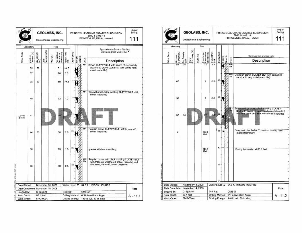
I 13 I 1.3 I,um I LL=65 I 47 I PI=26 .1.'1 1
_'""
44 1 73 1 1 38 12.5 I'u~
50 13
48 36
Approximate Ground Surface Elevation (feet MSL): 224 •
FT rplish brown CLAYEY SILT, stiff to very stiff,
moist (saprolite)
grades with black mottling
Plate
A-11.1
1
1
j ~
67
I 58 1
1 52
1 2 1
GEOLABS, INC.
Geotechnical Engineering
1 1
4
1 7
118/.3' Ref.
15/.1' Ref.
PRINCEVILLE GRAND ESTATES SUBDIVISION TMK: 5-3-06: 14
PRINCEVILLE, KAUAI, HAWAII
(Continued from previous
Description
Log of Boring
111
Plate
A - 11.2

GEOLABS, INC.
30 16
29 1 89 23
47 1 9
PRINCEVILLE GRAND ESTATES SUBDIVISION TMK: 5-3-06: 14
Log of Boring
PRINCEVILLE, KAUAI, HAWAII 112
1 1.3 1 '"-.:111 1
Approximate Ground Surface Elevation (feet MSL): 218 *
(saprolite)
45 1 -1 ,. .. I ,.-.'"-..rlW&I or lack~na
39 1 90 1 1 16 14.51·"~ 1 sana, StITT, mOist (saprolite)
57 4
56 8 grades to medium stiff to stiff
Not Encountered Plate
A - 12.1
,
,
,
LL=61 PI=24
51
1 46 1
GEOLABS, INC.
Geotechnical Engineering
13
PRINCEVILLE GRAND ESTATES SUBDIVISION TMK: 5-3-06: 14
PRINCEVILLE, KAUAI, HAWAII
(Continued from previous
1 22 1 2.0 I"· JW1.11 1 grades with grayish brown
Log of Boring
112
157 I 69_ I _., ,--.... ·FT·,·"" ...... 1 541 1 1 1
I I .. i tfJj I 11
16
55 1 65 11
Plate
A -12.2

• GEOLABS, INC.
Geotechnical Engineering
61 17
PRINCEVILLE GRAND ESTATES SUBDIVISION TMK: 5-3-06: 14
PRINCEVILLE, KAUAI, HAWAII
(Continued from previous
61 1681
I I 25 1
2.5
1 ou
Boring terminated at 81.5 fel
FT
Log of BOring
112
Plate
A - 12.3
1
1
i
GEOLABS, INC.
37 39
39 I 79 40
I 41 I I I I 13
I LL=56 I 38 PI=20
I 421761 1 1 21
43 23
43 17
PRINCEVILLE GRAND ESTATES SUBDIVISION TMK: 5-3-06: 14
PRINCEVILLE, KAUAI, HAWAII
Log of Boring
113
Approximate Ground Surface Elevation (feet MSL): 220 *
grades with black and tan mottling
Plate
A - 13.1

• GEOLABS, INC.
Geotechnical Engineering
~
42 10
59 5
52
48 7
56 13
44 I 78 32
PRINCEVILLE GRAND ESTATES SUBDIVISION TMK: 5-3-06: 14
PRINCEVILLE, KAUAI, HAWAII
Log of Boring
113
Plate
A -13.2
GEOLABS, INC.
47 28
42 I 81 42
PRINCEVILLE GRAND ESTATES SUBDIVISION TMK: 5-3-06: 14
PRINCEVILLE, KAUAI, HAWAII
(Continued from previous
Description
gray
Log of Baring
113
SILT with traces of fine sand, very stiff, moist (saprolite)
Plate
A-13,3

• GEOLABS, INC.
Geotechnical Engineering
34 I 75 16
21 LL=50 35 PI=24
31 I 82 48
33 25
44
45 12
44 29
PRINCEVILLE GRAND ESTATES SUBDIVISION TMK: 5-3-06: 14
PRINCEVILLE, KAUAI, HAWAII
Log of Boring
114
Approximate Ground Surface Elevation (feet MSL): 245 •
FT grades with black mottling
Plate
A - 14.1
~
GEOLABS, INC.
49
58 I 67
51
49
55
56 I 65
58
12
36
17
32
17
PRINCEVILLE GRAND ESTATES SUBDIVISION TMK: 5-3-06: 14
PRINCEVILLE, KAUAI, HAWAII
FT
Log of Boring
114
Plate
A-14.2

GEOLABS, INC.
52 I 68 49
55 I I I I 25 I 1.8 I
PRINCEVILLE GRAND ESTATES SUBDIVISION TMK: 5-3-06: 14
PRINCEVILLE, KAUAI, HAWAII
-- IWVl-1 I
Log of Boring
114
Plate
A -14.3
GEOLABS, INC.
Geotechnical Engineering
37 16
34 I 85 29
PRINCEVILLE GRAND ESTATES SUBDIVISION TMK: 5-3-06: 14
Log of Boring
PRINCEVILLE, KAUAI, HAWAII 115
Approximate Ground Surface Elevation (feet MSL): 262 •
'~~n I !~~:,~,:~ FT 53 I _
49 I 6a1 I I 14 I I J rrn I
49 19
Plate
A - 15.1
GEOLABS, INC.
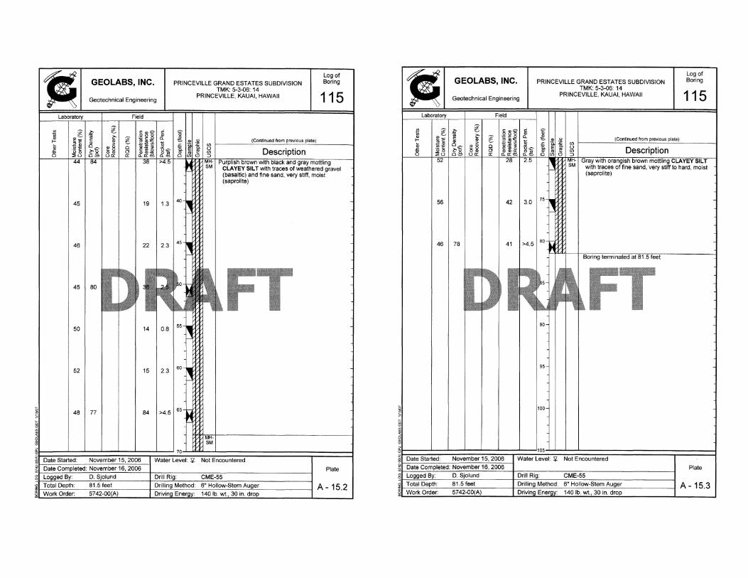
45 19
46 22
45
50 14
52 15
48 I 77 84
PRINCEVILLE GRAND ESTATES SUBDIVISION TMK: 5-3-06: 14
PRINCEVILLE, KAUAI, HAWAII
gray
Log of Boring
115
SILT with traces of weathered gravel (basaltic) and fine sand, very stiff, moist (saprolite)
FT
Plate
A - 15.2
• ! ~
GEOLABS, INC.
Geotechnical Engineering
PRINCEVILLE GRAND ESTATES SUBDIVISION TMK: 5-3-06: 14
PRINCEVILLE, KAUAI, HAWAII
Log of Boring
115
Plate
A - 15.3