sectio n 3 - ignition a nd - vintage sno 3-a.pdf · part a - flywheel magneto a n d thunderbolt...
TRANSCRIPT

SECTIO N 3 - IGNITION a ndELECTRICAL SYSTEMS
PART A - FLYWHEEL MAGNETO a n d
THUNDERBO LT IG NIT IO N
PARTS RE PLACEMENT
H1ERCURYSNOWMOBILES

e e
INDEXPage
Model 200 . .• . ..•... • . . . . . .•.• • . • .... . . ...3A-1Removal . . . .... . . ..•. . .•.. •. . . . . . ... . . .3A-1Disassembly . _ . .. • .. . ...... ..3A-1
Centrifugal Adva nce . .. . .. • • • . . . . • .. .3A-2Inspection • . . . .. .. .. . . . . .. . . . . . . . •. . . .3A-2Reassembly . • . •• . . .•. . . . • . . . . . . . . . . • . •3A·2Installation . ..•.• . • • . . . . . . . . • . •. • . .. . .. . .3A-2
Rocket (339cc) and Lightn ing (398cc) .• .. • . . .. • •. . . .. 3A3Removal • .• . . _ ...•. .• ..•. •. . . ••. ... . . . .3A-3Cent rifugal Advance •. •.. .••• . . . . . . . • . • • . • . •3A-3Inspection • . • . . • . . • • . • . . . . . . . . • . •. • . .• . .3A-4Component Part Rep lacement .•. .•. . .. .. : 3A-4
Breaker Points and Condensers .. . . ..... .. . . • ..3A-4Primary Ignition Coil • . ..•.• . • ... . . . . •. . • ••3A-4Lighting Coil ... . . . • . • . • • • . . • • . • • .. • . . .3A-4
Installation • . • ...• .•.••..••• •••.. . . • .. .• .3A-4Hurricane (644cc) . . . . . . . . • . . . . . • . . . . . . • . . . . .3A-5
Removal .. .• •... ... •. • . •. . .•• ... • . .• .. .3A-5Inspection •. • . ..• ... ..•. • . . . . . . . • . . •....3A-5Inst allation •. .. .. . . . . . .• . . . • . . .• ••• . . •. ..3A -5Centr if ugal Advance • . • . . . . .. .•. . . .• . ... ..••3A-Q
Removal .. . . . . . . . . . . . . . • . . . . . . . • . . .3A-QCleaning and Inspection " 3A-QInstallation . . . . . . . . . • . . . . . • 3A-Q
440 MAX, 440 MIX and 440 SIR 3A·7Removal . . . . . . . . . . . . .3A-7In spection . . .... ... . .. .. . . . .. . • ... . . ... .3A·7Compo nent Part Replacement ..... . . •. . . .. .. .. . .3A·7
Breaker Point s and Condensers •. • •• • . .. •.. •. .•3A -7Primary Igni ti on Coils . . • . . . .. •••.•. •... . . .3A-8Lighting Coil . ..•. . .. • •. . • •• • . . . •.. . . . •3A-8
Insta lla t ion • . • • • . . . • • . • • . . . • . • • . . • . • . . •3A-8Cent r if ugal Advance . . • . .. • . . . . • • •. • • . • • . . . .3A-9
Removal .. . . . . . . . . ... .. . . . •.• . . .3A-9Cleaning and Inspection .. •..• • .•. . .•. • . •.••3A-9Installation . . . . . • . .. . . . . . . . . . . . •..3A-9
Mark r and Mark n (644cc) . ..••• ••• ... •.• • . .• . • . 3A-1ORem oval •.•••. .. .. . . . • . .. .•• ••• .• .• . .. 3A ·10Inspection .. . ...• . . . .• . . . . ....... . .... . 3A -10Insta llation . • . . . • . . . . . . . • . . . . . . 3A -10Centr if ugal Advance .. .....• . ... . . .. 3A ·11
Removal . .. .. •.... 3A -11Cleaning and Inspectio n . . .. . . .. • .. . • . .. . 3A ·11Installation . . . . . . . 3A -11
340 SIT, 400 srt ,44 0 str , 340 rvr and 440 T rr .. 3A- 12Removal . .3A·12In spection . . 3A-12In stallation . . . . . . . . . . . . . . . . . . . . . . . . . 3A-12
340 SIR . . . . . . . 3A .13Removal . .3A-13Inspection . .3A -13Component Part Replacement . . 3A-1 3
Breaker Poi nts. . . . . . ... 3A- 13Primary Ign ition Coil. . . 3A -13Lighting Coils . . . . 3A-13Condensers 3A -13
Installation. . . . . . . . . 3A .14Centrifugal Advance . . . . 3A-14
Removal . . • . . . . . 3A-14Cleaning and Inspecti on . . . 3A -14Installat ion . . 3A-14
-
/
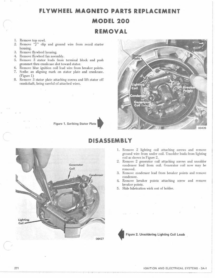
FLYWHEEL M AGN ETO PARTS REPLACEMENT
MODEL 200
REMOVAL
I
1. Remove top cowl.2. Remove "J" clip and ground wire from recoil starter
housing.3. Remove flywheel housing.4. Remove flywheel fan assemhly.5. Remove 3 stator leads from terminal block and push
grommet thru crankcase slot toward stator.6. Remove hlue ignition coil lead wire from breaker points.7. Scribe an aligning mark on stator plate and crankcase.
(Figure 1)8. Remove 3 stator plate attaching screws and lift stator off
crankshaft, heing careful of attached wires.
DISASSEMBLY
{ /
Ljght.~ing:':::"__-;iiCoil-
27 1, .
06427
1. Remove 2 lighting coil attaching screws and removeground wire from under coil. Unsolder leads from lightingcoil as shown in Figure 2.
2. Remove 2 generator coil attaching screws and unsoldercondenser lead from coil. Generator coil now may heremoved.
3. Remove condenser lead from hreaker points and removecondenser.
4. Remove breaker points attaching screw and removehreaker points .
5. Slide lubrication wick out of holder.
IGNITI ON AND ELECTRICAL SYSTEMS - 3A-1

- ------'"'---------~-11 59---------------------_......._----_........'.----CENTRIFUGAL A DVANCE
A spark advance mechanism is located inside the flywheel.Check to see if mechanism works freely in both directions . Ifnot , remo ve 3 common head screws which hold cam retain er.Rem ove horseshoe retainer from advance weight . Clean allparts and inspect for wear. Repla ce necessary parts andreassembl e and recheck . (Figure 3)
INSPECTI O N1. Visually inspect lead wires for cracks or breaks and breaker
points for b urned or pitted contact surface.2. Check spark advance lever and cam in flywheel/fan
assembly for wear and freedom of movement.
3. Test componen ts as explained in " Ignit ion and Electr icalSystem" Section 3B arid 3D.
4. Replace lubricatio n wick, if worn , or lubricate, if dry, withdrop of No. 30 oil.
REASSEMBLY1. Slide lubrication wick into retainer.2. Position lighting coil and ground wire on stator plate and
attach with 2 screws. Resolder coil leads with resin fluxsolder.
3. Install breaker points on stator plate .4. Install condenser in stator plate and carefully sta ke III
place.
5. Position generator coil on stator plat e and attach with 2screws. Solder generato r coil lead to condenser lead withresin flux solder and attach to br eaker points.
NOTE: Be sure that lead wires are not pinched under coils.
INSTALLATIO N1. Insert stator leads thru crankcase slot and blue ignition coil
lead thru stator plate. While pulling gently on wires, slidestator over cranksha ft. Set st ato r in place, align marks andattach with 3 screws.
2. Connect leads to terminal block and breaker poin ts .3. Lubri cate rubber grommet and install into crankcase slot,
being careful not to damage wire insulation.4. Install flywh eel fan assembly.5. Adjust points and time engine.6. Install flywh eel cover and rewind starter assembly.7. Attach ' '1'' clip and ground wire to rewind starter housing.8 . Install top cowl.
)
3A-2 - IGNITI ON AND ELECTR ICA L SYSTEMS 272R1

FL YWHEEL M AG N ETO PARTS REPLACEMENT
RO CKET (339cc) and LIGHTNIN G (398cc)
REMOVAL1. Open top cowl.2. Remove louvered dash panel. Rem ove lower air baffle and
4 dash attaching screws .3. Remove spark plug wires from spark plugs and position
dash as shown in Figure 1.
Figure 1. Dash Position
4. Remove spark plug lead wire retaining clip from engineshroud.
5. Disconnect wiring harness and remove tab housing andretainer from engine.
6. Remove rewind starte r assembly .7. Remove fan shroud.8. Remove upper pulley , fan belt , starter huh, lower fan
pulley and flywheel dust cover.9. Remove secondary ignition coil cover and ground wire.10 . Remove secondary ignition coils as an assembly. (Figure 2)n . Remove flywheel and back plate .
NOTE: Stator assembly need not be removed from enginefo r replacemen t of lighting coil, primary ignition coils,condensers or breaker points. When complete statorassembly is remo ved, it wiU be necessary to adjust breakerpoints and re-tim e engine at time of replacement.
Figure 2. Secondary Ignition Coils Removed
CENTRIFUGAL ADVANCEREMOVAL1. Remove flywheel.2. Remove snap ring from flywheel hub. (Figure 3)3. Scribe a location mark on flywheel huh and advance cam
for reference during reinstallation.4. Pull movable point cam off flywheel huh.5. Remove counterweight springs.6. Remove counterweight lockrings and remove counter
weight from flywheel stud, if necessary. Note location andnumber of spacer washers.
CLEA NING and INSPECTION1. Repl ace all damaged parts.2. Check cam fo r rough surfa ce which could cause pre
mature ignition point wear.
INSTALLATION1. Position counterweight and spacer washers on flywheel
stud. Secure with lockrings.2. Align scribe marks (made during removal) on flywheel huh
and advance cam. Slide advance cam into posit ion withcou nterweight ends in respective notches of advance cam.
3. Install snap ring retainer.272R l
Figure 3. Spark Advance Mechanism
IGN ITION AN D EL ECT R ICA L SYST EMS - 3A-3

1M
IN SPECTI O N1. Visually inspect lead wires for cracks or breaks and breaker
assemblies for burned or pitted contact surfaces.2. Check components as outlined in "Ignition and Electrical
Syst ems" Section 3B and 3D.
3. Check ignition advance cam, levers and springs in flywheelfor wear and freedom of movement.
4. Replace lubri cation wick, if worn , or lubricate , if dry , withdrop of 30 oil.
COMPONENT PART REP LACEMENTBREA KER POINTS and CONDENSERS
1. Remove condenser lead wires from breaker points andunsolder lead wires from condensers.
2. Remove breaker points, condensers and lubrication wickfrom stator plate by removing attaching screws.
3. Position new breaker points, condensers and lubri cationwick on stator plate and secure with attaching screws.(Figure 4)
Figure 4. Breaker Point and Condenser Location
4. Secure condenser leads to breaker points and solder leadwires to condensers.
5 . Adjust breaker points.
PRIMARY IGNIT ION COILS
1. Unsolder ignition coil lead wires from condensers.2 . Remove ignition coil attaching screws and spacer from
between ignition coils. .3. Position new ignition coils on stator plate and secure with
attaching screws. Ignition coil with red lead (No. 2cylinder) is on th e bottom, and coil with white lead (No.1
cylinder) is on top. Be sure that spacer washers are placedbetw een ignitio n coils.
4. Solder ignit ion coil leads to condensers.
LIGHTIN G COIL
1. Remove lightin g coil attaching screws.2. Cut yellow (2) light ing coil leads as close to lighti ng coil as
possible and remove coil.3. Solder yellow leads from lightin g coil to yellow leads fro m
tab housing with resin flux solder and protect with heatshrinkable sleeve or friction tape. (Figu re 5)
4. Tape spliced lead wire securely to lighting coil withfriction tape to prevent tangling with movable parts ofstator or flywh eel.
IMPORTANT: DO NOT use plastic type electrical tape. Aminimum of one layer of t ape must be placed betweensplice and coil.
5. Attach lighting coil to stator plate.
/ 't · hti C·19 tln9
Figure 5. Sleeve Installed on Splice
INSTALLA TION1. Install back plate, flywh eel housing and fan assembly.2. Connect engine and vehicle wiring harness. Secure tab
housing to flywhe el housing with retainer and 2 screws.3. Install ignition coils and coil cover. Be sure that ground
wire is attached with lower coil cover screw.4. Attach spark plug lead retaining clip to engine and spark
plug leads to spark plugs.5. Install dust cover, stato r hub, upp er and lower fan pulleys
3A-4 - IGN IT ION AND ELE CTR ICA L SYST EMS
and fan belt. Make certain t hat fan belt does not getpinch ed in upp er pulley durin g installation.
6. Install fan shroud .7. Install rewind star ter.8. Shift dash back int o position and attach dash and air inlet
baffle .9. Install louvered dash panel.10. Close top cowl.
272R l

FLYWHEEL MAGNETO PARTS REPLACEMENT
HURRICANE (644cc)
REM O V AL1. Open top cowl.2. Remove 6 phillips head screws and remove fan housing
rubber shro ud.3. Remove 7 allen head screws and remove rewind starte r.4. Remove rewind star ter ratchet from flywheel fan
assembly .5. Remove flywheel fan assembly as follows:
a. Install Modifi ed End Cap Puller (C-91-25733A3) onflywheel. (Figure 1)
TorqueWrench
_~PUller Plate
Figure 1. Flywheel Puller Installed
NOTE: Refer to Section 9 - "Tools" for modifi cationtemplate.
CAUTION: Puller plate screws can cause damage toadvance counterweights. if over-tightened. DO NOTuse a wrench. Hand-tighten only.
b. Hold flywheel with Flywheel Holder (C-91-52344),tighten puller center bolt to 45 ft . lbs. maximum andtap center bolt ONCE to free flywheel. H flywheeldoes not pop loose, tap each side of flywheel alternately, using wood block and hammer (while maintaining torque on center bolt) until flywheel is free.
6. Remove 4 nuts and washers from stato r and remove stator.7. Remove lubrication wick. Remove breaker points by
removing attaching screws and nuts. (F igure 2)8. Position new breaker points and secure with attaching
screws and nut s. Installluhrication wick. Install stator with4 washers and nut s.
9. Adjust breaker points. Refer to "Timing and Adjusting",Section 3C.
Figure 2. Breaker Points and Cam Wick
INSPECTION1. Visually inspect lead wires for cracks or breaks and breaker
assemblies for burned or pitted contact surfaces.2. Check components as outlined in "Ignition and Electrical
Systems" Section 3B and 3D.
3. Check ignition advance cam, levers and springs in flywheelfor wear and freedom of movement.
4. Replace lubrication wick, if worn, or lubricate, if dry, withdrop of 30 oil.
INSTALLATION1. Install flywheel fan assembly and torque to specifications.
Secure starter ratchet to flywheel.2. Install fan housing cover and rewind starter assembly.
272
3. Attach rubber air shroud to fan housing cover.4. Close top cowl.
IGN ITION A N D EL ECTR ICAL SYSTEMS · 3A·5

CENTRIFUGAL ADVANCE
REMOVAL
1. Remove flywheel.2. Remove screws and remove cam ret ainer. (Figure 3)3. Scribe a location mark on flywheel huh and advance cam
for reference during reinstallation.4. Pull movable point cam off flywh eel huh .5. Remove counte rweight springs .6. Remove counterweight lockrings and remove counter
weight from flywh eel stud, if necessary.
CLEANING and INSPECTION
1. Replace all damaged parts.2. Check cam for rough surface which could cause premature
ignition poin t wear .
INSTALLATION
1. Align scribe mark on flywheel huh and advance cam andinstall cam. Install cam retainers and secure with screws.
2. Install counterweights and secure with lockrings. (Figure3)
3A-6 - IGN IT ION AND ELECTRI CAL SYSTEM S
Ad vanc eWeightLockring
Spring
Figure 3. Spark Advance Mechan ism07317
272

FLYWHEEL MAGNETO PARTS REPLACEMENT440 MAX, 440 MIX and 440 SI R
REMO V A L1. Open top cowl and dashboard cover.2 . Remove spark plug wires from spark plugs.3. Remove dash attaching screws and position dash as shown
in Figure 1.4. Remove spark plug wire retaining clip from engine shroud.5. Disconnect engine wiring harness and secondary ignition
coil wires. Remove wiring harn ess connector retainer andengin e wiring harness conn ector from fan housing.
6. Remove rewind starte r assembly.7. Remove rewind starter pulley, fan pulley and dust cover (if
so equipped) from flyw hee l.8. Remove fan housing, seco ndary ignition coils and fan as
on e assembly.9. Remove flywheel (refer to Section SE) .
NOTE: It is not necessary to remove stator assembly fromengine for replacement of lighting coil, primary ignitioncoils, condensers or breaker points. When comple te statorassembly is removed, it will be necessary, however, toadjust breaker points and re-time engine at time ofreplacement.
INSPECTION
1. Visually inspect lead wires for cracks or breaks and breaker
assemblies for burned or pitted contact surfaces.
2. Check components as outlined in "Ignition and Electrical
Systems" Sections 3B and 3D.
3. Check ignition advance cam, levers and springs in flyw heelfor wear and freedom of movement.
4. Replace lubrication wick, if worn, or lubricate, if dry, withdrop of 30 oil.
5. Replace parts as necessary .
COMPONENT PA RT REPLACEMENT
BREAKE R POINTS and CONDE NSERS
1. Remove condenser lead wires from break er points andunsolder lead wires from condensers.
2 . Remove breaker points, condensers and lubrication wickfro m stator plate by removing attaching screws.
3. Position new breaker points, condensers and lubricationwick on st ato r plate and secure with attaching screws.(Figure 2)
4. Secure con denser leads to breaker po ints and solder leadwires to condensers.
5. Place fly whee l in position on crankshaft and adjust breakerpoints to spec ifications. (Refer to Sections 3C and 8.)
Figure 2. Breaker Point and Condenser Location
275R2 IGNITION AND ELECTRICAL SYSTEMS - 3A -7

,1i4 t t { 1
PRIMARY IGNITION COILS
1. Unsolder ignitio n coil lead wires from condensers.2 . Remove igniti on coil attaching screws and ignition coils
from stator plate.3. Positio n new ignition coils on stator plate and secur e with
attaching screws.4. Solder ignition coil leads to condensers.
LIGHTING COIL
1. Remove lighting coil attaching screws.2. Cut yellow (2) lighting coil wires as close to lighting coil as
possible and remove coil.3. Solder yellow leads from new lighting coil to yellow leads
fro m harn ess connec tor with resin flux solder and protectwith heat shrinkable sleeve or friction tap e. (Figure 3)
4. Tape spliced lead wire securely to lighting coil withfrictio n tap e to prevent tangling with movable parts ofstator of flywh eel.
IMPORTANT: DO NOT use plastic type electrical t ape. Aminimum of one layer of tape must be placed betweensplice and coil .
5. Attach lighting coil to stator plate. Figure 3. Sleeve Installed on Splic e
INSTALLATION1. Install flywheel.
NOTE: If breaker poin ts or stator plate were replaced, itwill be necessary to adjust breaker points and re-timeengine at th is time. (Ref er to Sections 3C and 8. )
2. Install fan housing, secondary ignition coils and fan as oneassembly.
3. Install du st cover (if so equipped), fan pulley and rewindstarter pulley on flywheel.
NOTE: Fan belt mus t be properly positioned on bothpulley s.
4. Install rewind starter assembly .
NO TE: Ground wire f rom cowl support' bracket must beattached to rewind attaching screw.
3A -8 - IG N ITION AND EL ECT RICA L SYSTEMS
5 . Secure engine WIfIng harness connector to fan housingwit h reta iner and screw .
6. Connect secondary ignition coil wires and wiring harn ess.7. Attach spark plug wires to engine shroud with retaining
clip.8 . Attach spark plug wires to spark plugs.9. Move dash into position on chassis and fasten with
attaching screws.
WARNING: Make sure that throttle retu rn spring isconnected to throttle ann on carburetor (if soequipped).
10 . Close dashboard cover.
11. Close top cowl.
1273R l
/

CENTRIFUGAL ADVANCE
REMOVAL
1. Remove flywheel. (Refer to Section 5E.)2 . Scrib e a location mark on flywh eel hub and advance cam
for reference during installation.3. Remove "E" rings which hold counterweights to flywh eel
stud. Note location of spacer washers. (Figure 4)4. Remove counterweight springs and counterweights from
flywhe el.5 . Align notches in advance cam with retaining arms and
remove cam .
CLEANING and INSPECTI ON
1. Replace all damaged parts.2. Check cam for rough surface which could cause premature
ignition point wear.
INSTA LLATI ON
1. Lubricate advance cam with Low Temperature Grease(C-92-59999-12) .
2 . Install advance cam on flywheel hub by aligning notches incam with retainin g arms on flywheel.
3. Align scribe mark (made in removal) on cam with mark onflywheel.
4. Install counterweights, counterweight springs and washers .Secure with "E" rings.
1272
Figure 4. Spark Advance Mechanism
5. Check advance cam for movement on flywh eel hub.6. Install flywheel.
IGN IT ION AND EL ECTRICAL SYSTEMS - 3A-9

'H ! J
FLYWHEEL IGNITION PARTS REPLACEMENTMARKl:(644cc} and
MARK:O: (644cc)
REMOVALL Open top cowl.2 . Disconnect battery cables fro m battery.3. Remove screws and "D" washers which secure harnesses
and wires to fan housing. Remove trigger wires fromswitchbox terminals (or wires) and stator wires fromrectifi er and switchbox terminals (or wires).
4 . Remove 2 bolts which fasten switchbox cover (if soequipped) and switchbox to fan housing. Position switch box and 'wiring harn esses away from fan housing.
NOTE: Remove rectifier assembly from fan housing onMark n snowmobiles with CHASSIS Serial No. 3787640and above.
5. Remove 7 allen head screws and remove fan housingassembly.
6 . Remove flywh eel fan assembly as follows:a. Remove recoil starter ratchet.b. Loosen flywh eel retaining bolt ~".c. Install End Cap Puller (C·91-25733A3) on flywh eel.
(Figure 1)
CAUTION: Puller plate bolts can cause damage toadvance counterweights. if over-tightened. DO NOTuse a wrench. Hand-tighten only.
d. Hold flywheel with Flywh eel Holder (C-91-52344),tighten puller center bolt to 45 ft. lbs. maximum andtap cen ter bolt ONCE to free flywh eel. If flywh eeldoes not pop loose, tap each side of flywh eel alt ernately, using wood block and hammer (whil e maintainingtorque on center bolt), until flywheel is free.
e. Remove fan and flywh cel assembly from engine.7 . Remo ve 4 screws from stator and remove stator and stator
support. (Figure 2)8 . Remove trigger plat e adjusting nut from carburetor side of
backplate. Move trigger plat e assembly away from backplate. Note position of 3 washers in end cap .
9. Remove 4 cap screws which hold backp late to crankcase .Pull backplate away from engine.
10 . Thread trigger and sta to r wires th ru backplate. (F igure 2)Remove trigger and stator assemblies.
!TorqueW rench(C-91-32610)
Figure 1. Flywheel Puller Installed
Figure 2. Tr igger Assembly
INSPECTION1. Visually inspect lead wires for cracks or .breaks.2. Check components as out lined in "Ignition and Electrical
Systems" Sect ions 3B and 3E.3. Replace parts as necessary.
INSTALLATIONNOTE: Use Loctite Grade A (C-92-32609-]) on all screwsand nuts. Refer to Section 8 fo r all torque specifi cations.
L Thread t rigger and sta to r wires thru backplat e.2 . Position backplate against engine and secure with cap
screws. Torque to specifications.3. Install trigger on backplate. For an initial setting, position
3A-l 0 · IGNITION A N D EL ECT RICAL SYS TE MS
tr igger adj usting bolt in center of adj ust ing slot and securewith nut,
NOTE: Washers (located in end cap) mus t be in properposition. Wave washer shou ld be bet ween fla t washers.
4. Install stato r support and stato r with 4 screws. Torque tospecificatio ns.
127 3R l

5. In stall flywheel, fan and recoil starte r ratchet. Torqueflywheel and recoil starter rat chet to spec ificat ions.
6. Using 7 allen head screws, attach fan housing assembly tobackplate. Torque to specifications.
7. Attach switchbox and switchbox cover (if so eqipped) tofan housing. Torque to specification s.
NOTE: Install rectifi er assem bly on fa n housing on Mark IIsnowm obiles with CHASSIS Serial No . 3787640 andabove.
8. Attach trigger wires to switchbox terminals (or wires) andstator wires to recti fier and switchhox terminals (or wires).
NOTE: Ins ulate terminals of switch box and rectifier withLiquid Neoprene (C-92-25711 ·1). If switchbox is equipped
with wires instead of terminals, install new heat shrinkablesleeves over wire connections.
9. Attach harnesses and wires to fan housing with screws and"D " washers .
10. Connec t battery cables t o battery.
CAUTION : Connect red cable to positive (+) terminaland black cable to negative (-) terminal. Failure toobserve correct polarity will result in destruction ofrectifier and/or switchbox.
11. Refer to "Ignition and Electrical Syst ems" Secti on 3C andadjust engine timing .
12. Close top cowl.
CENTRIFUGAL ADVANCEREMOVAL
1. Remove flywheel. (Refer t o Section 5D.)2. Scrib e a locatio n mark on flywheel hub and advance rotor
for reference during reinstallation.3. Remove rotor retainer attaching scre ws and counte rweight
"E" rings. (Figure 3)4. Remove rotor retainers, coun terweights and counterweight
spring(s) from flywheel.
IMPORTANT: Mark II Models ONLY shou ld be equippedwith one (1) coun te rweight spring rather than two, as
775R2
----............---
shown in Figure 3. Mark II Snowmobiles with CHASSISSerial No. 359 1478 and below were factory-equipped withtwo counterweight springs. A service modification requiresremoval of one (1) counterweight spring from thesesnowmohiles, Mark II snowmobiles with CHASSIS SerialNo. 3787640 and above were factory-equipped with one(1) counterweight spring.
5. Pull advance rotor off flywheel huh.
CLEANING and INSPECTION
1. Replace all worn or bent parts.2 . Check rotor for rough surface which could cause pre
mature failure .
INSTALLATI ON
1. Lubricate advance rotor with Low Temperature Grease(C-92-S9999-12).
2. Install ro to r and align scribe mark on flywheel huh withscrib e mark on advance rotor.
3. Install rotor retainers, counterweights and counterwe ightspring(s) in flywheel. (Figure 3)
4. Fasten rotor retai ners with screws and counterweights withlockrings.
5. Check advance rotor for move ment on flywheel hub.6. Install flywheel. (Refer to "Specifications" Section 8 for
torque specifications.)
• F;",,, . 3. Spark Ad..nee Mech.n ;""
IGNITION A ND ELECTRICAL SYSTEMS - 3A-11

fa Ii
FLYWHEEL IGNITION PARTS REPLACEMENT340 SIT, 400 SIT, 440 SIT, 340 TIT and 440 TIT
REMOVALI. Open top cowl and remove carburetor air intake.2. Remove exhaust pipe(s) and rewind st arte r assembly.3. Remove rewind starter pulley and flywh eel sheave(s) from
flywheel.4. Remove flywhee l. (R efer to Section 5.)5 . Disconnect trigger and stator wires.6. Remove stator assembly and trigger assembly attaching
bol ts. (Figure 1)
NO TE: If only stator assembly will be replaced, it is notnecessary to loosen trigger assembly attaching bolts.
7. Remove screws, which secure flywh eel bell housing (or fanhousing) , and pull housing with trigger and stator assemblies from crankshaft . On 400 S/T , note pos ition ofshim(s) and "0" ring on flywheel bell housing.
8. Remove trigger and stator harnesses from crankcasegro mmet.
9. Thread trigger and stator harnesses thru flywhee l bellhousing. Remove trigger and stator assemblies.
.Figure 1. Removing Stator and Trigger Assemblies
IN SPECTIO NI. Visually inspect harness wires and connecto rs fo r cracks
and breaks.2. Check components as outlined in " Ignition and Electrical
Systems" Sections 3B and 3D. Replace parts as necessary.
INSTALLATIONI. On 400 S/T, lubricate flywh eel bell housing oil seal and
"0 " ring with a small amount of Mult ipurpose Lub ricant(C-92-63250) .
2 . Th read t rigger and stator harnesses thru hole in flywh eelbell ho using (or fan housing).
3. Position tr igger and stator harnesses in crankcase grommetand housing against crank case. Secure housing to crankcasewith attaching bolts. To rq ue bo lts to specification. (Referto "Specificat ions" Section 8).
IMPORTANT: On 40 0 srr, be sure shim(s) and "0" ringare properly positioned between flywheel bell housing andcrankcase. Same shim(s), which were removed, MUST bereinstalled.
4. Place trigger assembly in pos itio n on flywh eel bell housingand secure with atta ching bolts. (F igure 1)
3A-12 - IGNIT ION AND ELECTR ICAL SYST EMS
5. Refer to "Ignition and Electrical Systems" Section 3C andadjust engine timing. Reinstall spark plugs after t imingengtne.
6. After timing engine, install stato r assembly. (F igure 1)7 . Connect trigger and stator wires.8. Install and secure flywheel. (Refer to Section 5.)9 . Place flywheel sheave(s) and rewind starter pulley in
position on flywhee l and secure to flywheel with attachingbolts.
10 . Install rewind starte r assembly and carbureto r air intake.
NOTE: Wirers) should be reattached to rewind starterattaching bolt.
I I. Install exhaust pipe(s) and close top cowl.
775R2

FLYWHEEL M AGNETO PARTS REPLACEMENT340 SIR
REMOVAL1. Remove rewind starter assembly.2. Remove rewind starter pulley and lower fan pulley halves
from flywheel.3. Remove flywheel (refer to Section 5) .
NO TE: It is not necessary to remove stator assembly fr om
engine for replacement of lighting co ils, p rimary ignit ioncoil or breaker po ints. Removal of stator assembly will berequired for replacement of condensers. If stator assemblyis removed or breaker points replaced , it will be necessaryto adjust breaker points and re-time engine during installation.
INSPECTION
1. Visually inspect wires for cracks or breaks and breakerassemblies for burned or pitted contact surfaces.
2. Check components as outlined in " Ignition and ElectricalSyste ms" Sections 3B and 3D.
3. Check flywheel centrifugal advance as outlined, following.4. Replace lubrication wick, if worn, or lubricate, if dry, with
a drop of 30 weight oil.5. Replace parts as necessary.
COMPONENT PART REPLACEMENTBREA KER POINTS (Figure 1)
1. Disconnect wires from each set of breaker po int s.2. Remove breaker point assemblies by removing atta ching
screws.3. Position new breaker points and secure to stator plate with
attaching screws.4. Connect wires to breake r points.5. Place flywheel in position on crankshaft and adjust breaker
po int gaps to specificat ions . (Refer to Sectio ns 3C and 8 .)
PRIMA RY IGN IT ION COIL (Figure 1)
1. Unsolder black ignit ion coil wires from condensers.2 . Remove screws which secure small lighting coil and
primary ignition coil to stator plate.3. Replace old ignition coil with new ignition coil.4. Secure primary ignitio n coil, spacers and small lighting coil
to stator plate with attaching screws.5 . Solder ignition coil wires to conden sers.
LIGHT ING COILS (Figure 1)
NOTE: Two lighting coils are mounted on stator plate.One lighting coil (small coil) has a green wire and agreen/black wire at tached, and the other lighting coil (largecoil) has a ye llow wire and a yellow/green wire at tached.
1. Remove lighting coil attaching screws.2. Cut 2 lighti ng coil wires (from coil which is being rep laced)
as close to lighting coil as possibl e and remove coil.3. Splice wires from new lighting coil to wires which were cut
from old coil. Solder wires with resin flux solder andprotect with heat shrinkable sleeve or friction tape .
4. Tape spliced wires securely to lighting coil with frict iontape to prevent tangling wit h movable parts of flywh eelmagneto .
IMPORTANT: DO NOT use plastic type electrical tape. Aminimum of one layer of tape must be placed betweensplice and lighting coil.
275
Figure 1. Stator Plate Assembly
5. Place light ing coil in position on stator plate and securewith attaching screws.
CONDENSERS (F igure 1)
1. Remove stator plate assembly fro m engine.2. Unsolder wires from each condenser.3. Support sta to r plate with suitab le mandrel and press each
condenser from stator plat e.
CAUTION: To avoid damaging stator plate , be surethat stato r plate is properly supported when pressingon condensers. Con densers are "Locti ted" and stakedin place. Stator plate may require heat (applied at baseof each condenser ) to aid in removal of condensers.
4. Place a thin bead of Loctite Type "A" (C-92-32609)around base of each conde nser. Install each condenser intoposit ion in stator plat e by pressing on bottom of condensers.
5. Solder wires to condensers.6. Reinstall stator plate assembly on engine .
IGN IT ION A ND EL ECT RICA L SYST EMS · 3A -13

INSTALLATION1. Install flyw heel.
NOTE: If breaker points were replaced or stator plate wasremoved, it is necessary to adjust breaker po int gaps andre-time engine at this time. (Refer to Sections 3C and 8.)
2. Place fan belt between halves of lower fan pulley andsecure fan pulley halves and rewind starte r pulley toflywhee l.
3. Install rewind starte r assembly .
CENTRIFUGAL ADVANCEREMOVAL
1. Remove flywheel. (Refer to Section 5.)2 . Remove screws which secure advance cam ret aining
brackets to flywheel. (Figure 2) Lift retaining brackets andadvance cam from flywheel.
3. Remove "E" ring which holds counterweight to flywheelstud. (Figure 2)
4. Lift counterweight, counterweight spring and brass washerfrom flywheel.
CLEA NING and INSPECTION
1. Clean and inspect all parts. Replace all damaged or wornparts.
2. Check advance cam for rough surface which could causepremature ignition point wear.
INSTALLATION
1. Lubricate advance cam, flywheel stud and counterweightwith a thin coat of Low Temperature Grease (C-92-S9999).
2. Install brass washer, counterweight and counterweightspring in position in flywheel. (Figure 2)
3. Secure counterweight with "E" ring . (Figure 2)4 . Align slot in advance cam with counterweight and install
cam.5. Install advance cam retaining brackets and secure with
lockwashers and screws .
3A-1 4 - IGN ITION AND ELECTR ICAL SYSTEMS
Figure 2. Centrifugal Advance Mechanism
6. Check advance cam for movement on flywheel hub.7 . Install flywheel.
09 166
275