second law of thermodynamics and entropy · third law of thermodynamics—highlights—objective...
TRANSCRIPT
5Second Law of Thermodynamics and Entropy
5.1. Limitations of first law of thermodynamics and introduction to second law. 5.2. Performanceof heat engines and reversed heat engines. 5.3. Reversible processes. 5.4. Statements of secondlaw of thermodynamics—Clausius statement—Kelvin-planck statement—Equivalence of clausiusstatement to the kelvin—Planck statement. 5.5. Perpetual motion machine of the second kind.5.6. Thermodynamic temperature. 5.7. Clausius inequality. 5.8. Carnot cycle. 5.9. Carnot’stheorem. 5.10. Corollary of Carnot’s theorem. 5.11. Efficiency of the reversible heat engine.5.12. Entropy—Introduction—Entropy—A property of a system—Change of entropy in a reversibleprocess. 5.13. Entropy and irreversibility. 5.14. Change in entropy of the universe.5.15. Temperature—Entropy diagram. 5.16. Characteristics of entropy. 5.17. Entropy changesfor a closed system—General case for change of entropy of a gas—Heating a gas at constantvolume—Heating a gas at constant pressure—Isothermal process—Adiabatic process—Polytropicprocess—Approximation for heat absorbed. 5.18. Entropy changes for an open system. 5.19. Thethird law of thermodynamics—Highlights—Objective Type Questions—Theoretical Questions—Unsolved Examples.
5.1. LIMITATIONS OF FIRST LAW OF THERMODYNAMICS AND INTRODUCTIONTO SECOND LAW
It has been observed that energy can flow from a system in the form of heat or work. Thefirst law of thermodynamics sets no limit to the amount of the total energy of a system which canbe caused to flow out as work. A limit is imposed, however, as a result of the principle enunciatedin the second law of thermodynamics which states that heat will flow naturally from one energyreservoir to another at a lower temperature, but not in opposite direction without assistance. Thisis very important because a heat engine operates between two energy reservoirs at different tem-peratures.
Further the first law of thermodynamics establishes equivalence between the quantity ofheat used and the mechanical work but does not specify the conditions under which conversion ofheat into work is possible, neither the direction in which heat transfer can take place. This gaphas been bridged by the second law of thermodynamics.
5.2. PERFORMANCE OF HEAT ENGINES AND REVERSED HEAT ENGINES
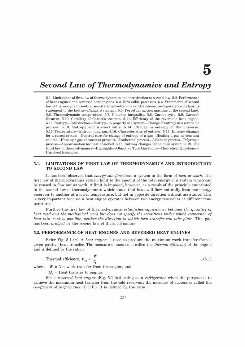
Refer Fig. 5.1 (a). A heat engine is used to produce the maximum work transfer from agiven positive heat transfer. The measure of success is called the thermal efficiency of the engineand is defined by the ratio :
Thermal efficiency, ηth = WQ1
...(5.1)
where, W = Net work transfer from the engine, andQ1 = Heat transfer to engine.
For a reversed heat engine [Fig. 5.1 (b)] acting as a refrigerator when the purpose is toachieve the maximum heat transfer from the cold reservoir, the measure of success is called theco-efficient of performance (C.O.P.). It is defined by the ratio :
227
228 ENGINEERING THERMODYNAMICS
dharm/M-therm/th5-1.pm5
Co-efficient of performance, (C.O.P.)ref. = QW
2 ...(5.2)
where, Q2 = Heat transfer from cold reservoir, and W = The net work transfer to the refrigerator.For a reversed heat engine [Fig. 5.1 (b)] acting as a heat pump, the measure of success is
again called the co-efficient of performance. It is defined by the ratio :
Co-efficient of performance, (C.O.P.)heat pump = QW
1 ...(5.3)
where, Q1 = Heat transfer to hot reservoir, and W = Net work transfer to the heat pump.
Hotreservoir
Heatengine
Coldreservoir
Hotreservoir
Heat pumpor refrigerator
Coldreservoir
Q1
Q2 Q2
Q = Q + W1 2
W = (Q – Q )1 2 W
(a) (b)Heat engine Heat pump or refrigerator
Fig. 5.1
In all the above three cases application of the first law gives the relation Q1 – Q2 = W, andthis can be used to rewrite the expressions for thermal efficiency and co-efficient of performancesolely in terms of the heat transfers.
ηthQ Q
Q= −1 2
1..(5.4)
(C.O.P.)ref = −Q
Q Q2
1 2...(5.5)
(C.O.P.)heat pump =−Q
Q Q1
1 2
..(5.6)
It may be seen that ηth is always less than unity and (C.O.P.)heat pump is always greater thanunity.
5.3. REVERSIBLE PROCESSES
A reversible process should fulfill the following conditions :1. The process should not involve friction of any kind.2. Heat transfer should not take place with finite temperature difference.

SECOND LAW OF THERMODYNAMICS AND ENTROPY 229
dharm/M-therm/th5-1.pm5
3. The energy transfer as heat and work during the forward process should be identicallyequal to energy transfer as heat and work during the reversal of the process.
4. There should be no free or unrestricted expansion.5. There should be no mixing of the fluids.6. The process must proceed in a series of equilibrium states.
Some examples of ideal reversible processes are :(i) Frictionless adiabatic expansion or compression ;
(ii) Frictionless isothermal expansion or compression ;(iii) Condensation and boiling of liquids.Some examples of irreversible processes are :(i) Combustion process ; (ii) Mixing of two fluids ;
(iii) All processes involving friction ; (iv) Flow of electric current through a resistance ;(v) Heat flow from a higher temperature to lower temperature.Reversible processes are preferred because the devices which produce work such as engines
and turbines, reversible process of the working fluid delivers more work than the correspondingirreversible processes. Also in case of fans, compressors, refrigerators and pumps less power inputis required when reversible processes are used in place of corresponding irreversible ones.
In thermodynamic analysis concept of reversibility, though hypothetical, is very importantbecause a reversible process is the most efficient process. Only reversible processes can be truelyrepresented on property diagrams. Thermodynamic reversibility can only be approached but cannever be achieved. Thus the main task of the engineer is to design the system which will evolveapproximate reversible processes.
5.4. STATEMENTS OF SECOND LAW OF THERMODYNAMICS
The second law of thermodynamics has been enunciated meticulously by Clausius, Kelvinand Planck in slightly different words although both statements are basically identical. Eachstatement is based on an irreversible process. The first considers transformation of heat betweentwo thermal reservoirs while the second considers the transformation of heat into work.
5.4.1. Clausius Statement“It is impossible for a self acting machine working in a cyclic process unaided by any
external agency, to convey heat from a body at a lower temperature to a body at a highertemperature”.
In other words, heat of, itself, cannot flow from a colder to a hotter body.
5.4.2. Kelvin-Planck Statement“It is impossible to construct an engine, which while operating in a cycle produces no other
effect except to extract heat from a single reservoir and do equivalent amount of work”.Although the Clausius and Kelvin-Planck statements appear to be different, they are really
equivalent in the sense that a violation of either statement implies violation of other.
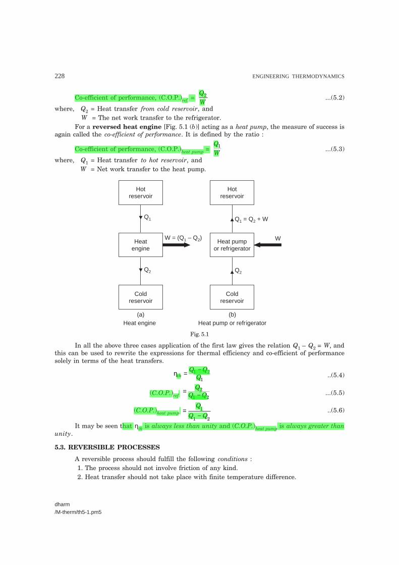
5.4.3. Equivalence of Clausius Statement to the Kelvin-Planck StatementRefer Fig. 5.2. Consider a higher temperature reservoir T1 and low temperature reservoir
T2. Fig. 5.2 shows a heat pump which requires no work and transfers an amount of Q2 from a lowtemperature to a higher temperature reservoir (in violation of the Clausius statement). Let anamount of heat Q1 (greater than Q2) be transferred from high temperature reservoir to heat enginewhich devolops a net work, W = Q1 – Q2 and rejects Q2 to the low temperature reservoir. Sincethere is no heat interaction with the low temperature, it can be eliminated. The combined system
230 ENGINEERING THERMODYNAMICS
dharm/M-therm/th5-1.pm5
of the heat engine and heat pump acts then like a heat engine exchanging heat with a singlereservoir, which is the violation of the Kelvin-Planck statement.
High temp. reservoir, T1
Low temp. reservoir, T2
Heatpump
Heatengine
W = Q – Q1 2
Q1
Q2
Q1
Q2
Systemboundary
Fig. 5.2. Equivalence of Clausius statement to Kelvin-Planck statement.
5.5. PERPETUAL MOTION MACHINE OF THE SECOND KIND
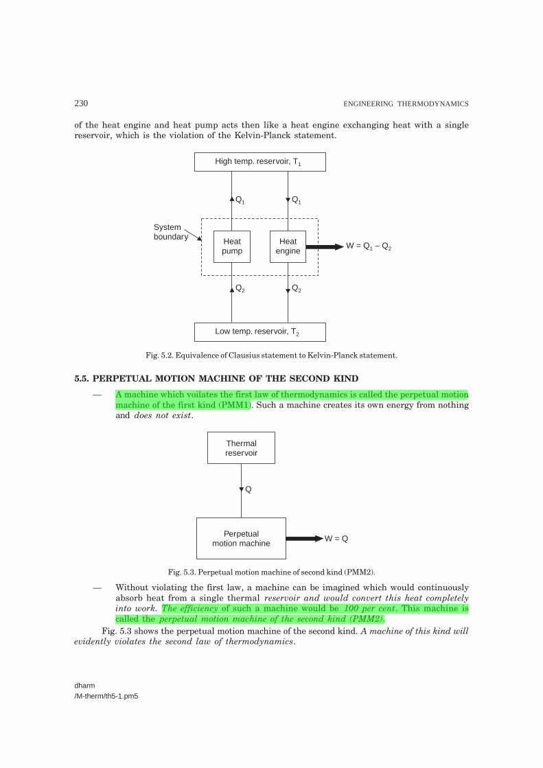
— A machine which voilates the first law of thermodynamics is called the perpetual motionmachine of the first kind (PMM1). Such a machine creates its own energy from nothingand does not exist.
Thermalreservoir
Perpetualmotion machine
W = Q
Q
Fig. 5.3. Perpetual motion machine of second kind (PMM2).
— Without violating the first law, a machine can be imagined which would continuouslyabsorb heat from a single thermal reservoir and would convert this heat completelyinto work. The efficiency of such a machine would be 100 per cent. This machine iscalled the perpetual motion machine of the second kind (PMM2).
Fig. 5.3 shows the perpetual motion machine of the second kind. A machine of this kind willevidently violates the second law of thermodynamics.
SECOND LAW OF THERMODYNAMICS AND ENTROPY 231
dharm/M-therm/th5-1.pm5
5.6. THERMODYNAMIC TEMPERATURE
Take the case of reversible heat engine operating between two reservoirs. Its thermal effi-ciency is given by the eqn. (5.4),
ηth = Q Q
Q1 2
1
− = 1 –
2
1
The temperature of a reservoir remains uniform and fixed irrespective of heat transfer.This means that reservoir has only one property defining its state and the heat transfer from areservoir is some function of that property, temperature. Thus Q = φ (K), where K is the tempera-ture of reservoir. The choice of the function is universally accepted to be such that the relation,
KK
1
2
1
2=
φφ
( )( ) becomes
TT
1
2
1
2= ...(5.7)
where T1 and T2 are the thermodynamic temperatures of the reservoirs. Zero thermodynamictemperature (that temperature to which T2 tends, as the heat transfer Q2 tends to zero) has neverbeen attained and one form of third law of thermodynamics is the statement :
‘‘The temperature of a system cannot be reduced to zero in a finite number ofprocesses.”
After establishing the concept of a zero thermodynamic temperature, a reference reservoiris chosen and assigned a numerical value of temperature. Any other thermodynamic temperaturemay now be defined in terms of reference value and the heat transfers that would occur withreversible engine,
T = Tref. Q
Qref ....(5.8)
The determination of thermodynamic temperature cannot be made in this way as it is notpossible to build a reversible engine. Temperatures are determined by the application of thermody-namic relations to other measurements.
The SI unit of thermodynamic temperature is the kelvin (K). The relation between thermo-dynamic temperature and celsius scale, which is in common use is :
Thermodynamic temperature = Celsius temperature + 273.15°.
The kelvin unit of thermodynamic temperature is the fraction 1
273.15 of thermodynamic
temperature of ‘Triple point’ of water.
5.7. CLAUSIUS INEQUALITY
When a reversible engine uses more than two reservoirs the third or higher numberedreservoirs will not be equal in temperature to the original two. Consideration of expression forefficiency of the engine indicates that for maximum efficiency, all the heat transfer should takeplace at maximum or minimum reservoir temperatures. Any intermediate reservoir used will,therefore, lower the efficiency of the heat engine. Practical engine cycles often involve continu-ous changes of temperature during heat transfer. A relationship among processes in whichthese sort of changes occur is necessary. The ideal approach to a cycle in which temperaturecontinually changes is to consider the system to be in communication with a large number ofreservoirs in procession. Each reservoir is considered to have a temperature differing by asmall amount from the previous one. In such a model it is possible to imagine that eachreservoir is replaced by a reversible heat engine in communication with standard reservoirsat same temperature T0. Fig. 5.4 shows one example to this substitution.

232 ENGINEERING THERMODYNAMICS
dharm/M-therm/th5-1.pm5
T + Tδ T0
TOriginalsystem
boundary
δQ
δW
δWR
Reversibleheat engine
δQ
New systemboundary
(a) (b)
Fig. 5.4. The clausius inequality.
The system to which the heat transfer is effected is neither concerned with the source ofenergy it receives nor with the method of transfer, save that it must be reversible. Associated withthe small heat transfer dQ to the original system is a small work transfer dW and for this systemthe first law gives
( )δ δQ W− =∑ 0cycle
...(5.9)
Now consider the engine replacing the reservoirs and apply the second law to the newsystem in Fig. 5.4 (b). If the new system is not a perpetual motion machine of second kind, nopositive work transfer is possible with a single reservoir.
Therefore,( )δ δW WR− ≤∑ 0
cycle...(5.10)
But by the definition of thermodynamic temperature in equation (5.8)
δδ
δ δδ
WQ
Q QQ
T TT
R = − = −0 0 ...(5.11)
and by combination of eqns. (5.9), (5.10) and (5.11)
TQT0δ������∑
cycle ≤ 0 but T0 ≠ 0 and therefore ;
δQT���
���
≤∑cycle
0 ..(5.12)
This is known as Clausius inequality.Let us now consider the case of a reversible engine for which
δQT���
���
≤∑cycle
0 ,
SECOND LAW OF THERMODYNAMICS AND ENTROPY 233
dharm/M-therm/th5-1.pm5
reverse the engine and for the reversible heat pump obtained it is possible to develop theexpression,
− ������
≤∑ δQT
cycle
0
The negative sign indicates that the heat transfers have all reversed in direction when theengine was reversed. This means that for the same machine we have two relations which are onlysatisfied if in the reversible case,
δQT������
≤∑cycle
0 ...(5.13)
For a reversible case, as the number of reservoirs used tends to infinity, the limiting valueof the summation will be
δQT������
=∑cycle
0
In words, the Clausius inequality may be expressed as follows :“When a system performs a reversible cycle, then
δQT������∑
cycle = 0,
but when the cycle is not reversible
δQT������
<∑cycle
0 ’’.
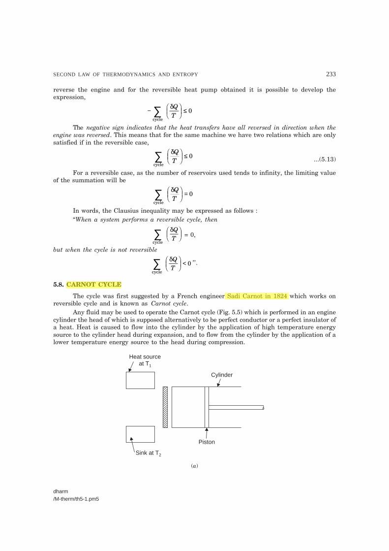
5.8. CARNOT CYCLE
The cycle was first suggested by a French engineer Sadi Carnot in 1824 which works onreversible cycle and is known as Carnot cycle.
Any fluid may be used to operate the Carnot cycle (Fig. 5.5) which is performed in an enginecylinder the head of which is supposed alternatively to be perfect conductor or a perfect insulator ofa heat. Heat is caused to flow into the cylinder by the application of high temperature energysource to the cylinder head during expansion, and to flow from the cylinder by the application of alower temperature energy source to the head during compression.
Heat sourceat T1
Sink at T2
Piston
Cylinder
(a)
234 ENGINEERING THERMODYNAMICS
dharm/M-therm/th5-1.pm5
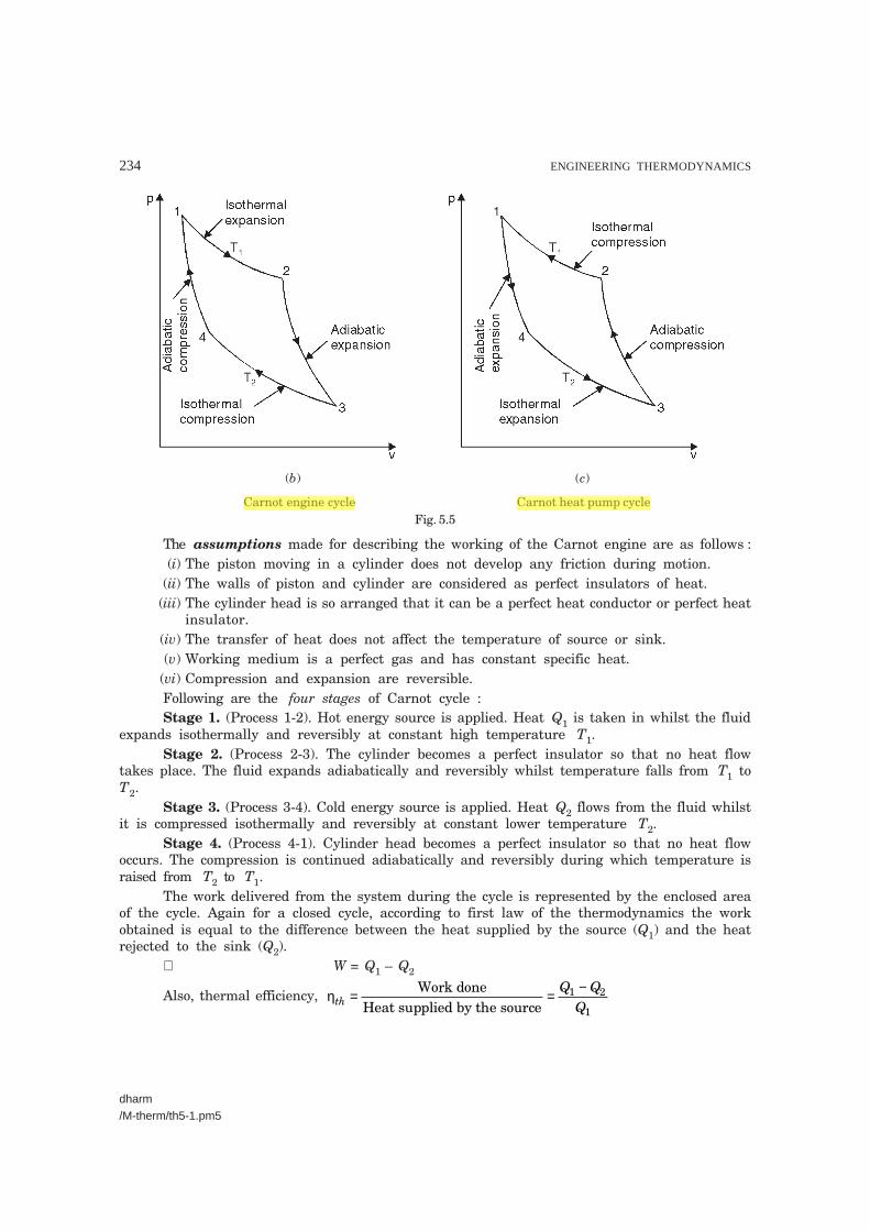
(b) (c)
Carnot engine cycle Carnot heat pump cycleFig. 5.5
The assumptions made for describing the working of the Carnot engine are as follows :(i) The piston moving in a cylinder does not develop any friction during motion.
(ii) The walls of piston and cylinder are considered as perfect insulators of heat.(iii) The cylinder head is so arranged that it can be a perfect heat conductor or perfect heat
insulator.(iv) The transfer of heat does not affect the temperature of source or sink.(v) Working medium is a perfect gas and has constant specific heat.
(vi) Compression and expansion are reversible.Following are the four stages of Carnot cycle :Stage 1. (Process 1-2). Hot energy source is applied. Heat Q1 is taken in whilst the fluid
expands isothermally and reversibly at constant high temperature T1.Stage 2. (Process 2-3). The cylinder becomes a perfect insulator so that no heat flow
takes place. The fluid expands adiabatically and reversibly whilst temperature falls from T1 toT2.
Stage 3. (Process 3-4). Cold energy source is applied. Heat Q2 flows from the fluid whilstit is compressed isothermally and reversibly at constant lower temperature T2.
Stage 4. (Process 4-1). Cylinder head becomes a perfect insulator so that no heat flowoccurs. The compression is continued adiabatically and reversibly during which temperature israised from T2 to T1.
The work delivered from the system during the cycle is represented by the enclosed areaof the cycle. Again for a closed cycle, according to first law of the thermodynamics the workobtained is equal to the difference between the heat supplied by the source (Q1) and the heatrejected to the sink (Q2).
∴ W = Q1 – Q2
Also, thermal efficiency, ηthQ Q
Q= = −Work done
Heat supplied by the source1 2
1

SECOND LAW OF THERMODYNAMICS AND ENTROPY 235
dharm/M-therm/th5-1.pm5
= − = −�
���
��1 12
1
2
1
TT
� Q m c TQ m c T
m
p
p
1 1
2 2
===
�
�
�
���where, mass of fluid.
Such an engine since it consists entirely of reversible processes, can operate in the reversedirection so that it follows the cycle shown in Fig. 5.5 (b) and operates as a heat pump. Q2 is beingtaken in at the lower temperature T2 during the isothermal expansion (process 4-3) and heat Q1 isbeing rejected at the upper temperature T1 (process 2-1). Work W will be needed to drive the pump.Again, the enclosed area represents this work which is exactly equal to that flowing from it whenused as engine.
The Carnot cycle cannot be performed in practice because of the following reasons :1. It is imposible to perform a frictionless process.2. It is impossible to transfer the heat without temperature potential.3. Isothermal process can be achieved only if the piston moves very slowly to allow heat
transfer so that the temperature remains contant. Adiabatic process can be achieved only if thepiston moves as fast as possible so that the heat transfer is negligible due to very short timeavailable. The isothermal and adiabatic processes take place during the same stroke therefore thepiston has to move very slowly for part of the stroke and it has to move very fast during remainingstroke. This variation of motion of the piston during the same stroke is not possible.
5.9. CARNOT’S THEOREM
“It states that of all engines operating between a given constant temperaturesource and a given constant temperature sink, none has a higher efficiency than areversible engine”.
Refer Fig. 5.6.
Fig. 5.6. Two cyclic heat engines HEA and HEBoperating between the same source and sink, of which HEB is reversible.
HEA and HEB are the two engines operating between the given source at temperature T1and the given sink at temperature T2.
236 ENGINEERING THERMODYNAMICS
dharm/M-therm/th5-1.pm5
Let HEA be any heat engine and HEB be any reversible heat engine. We have to prove thatefficiency of HEB is more than that of HEA. Let us assume that ηA > ηB. Let the rates of working ofthe engines be such that
Q1A = Q1B = Q1Since ηA > ηB
WQ
WQ
A
A
B
B1 1>
∴ WA > WB
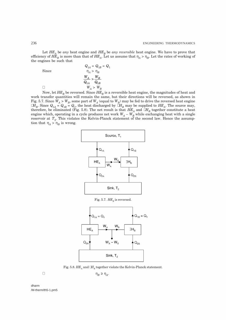
Now, let HEB be reversed. Since HEB is a reversible heat engine, the magnitudes of heat andwork transfer quantities will remain the same, but their directions will be reversed, as shown inFig. 5.7. Since WA > WB, some part of WA (equal to WB) may be fed to drive the reversed heat engine∃ HB. Since Q1A = Q1B = Q1, the heat discharged by ∃ HB may be supplied to HEA. The source may,therefore, be eliminated (Fig. 5.8). The net result is that HEA and ∃ HB together constitute a heatengine which, operating in a cycle produces net work WA – WB while exchanging heat with a singlereservoir at T2. This violates the Kelvin-Planck statement of the second law. Hence the assump-tion that ηA > ηB is wrong.
Fig. 5.7. HEB is reversed.
Fig. 5.8. HEA and ∃ HB together violate the Kelvin-Planck statement.
∴ η B ≥ ηA.

SECOND LAW OF THERMODYNAMICS AND ENTROPY 237
dharm/M-therm/th5-1.pm5
5.10. COROLLARY OF CARNOT’S THEOREM
‘‘The efficiency of all reversible heat engines operating between the sametemperature levels is the same”.
Refer Fig. 5.6. Let both the heat engines HEA and HEB be reversible. Let us assumeηA > ηB. Similar to the procedure outlined in the Article 5.9, if HEB is reversed to run say, asa heat pump using some part of the work output (WA) of engine HEA, we see that the combinedsystem of heat pump HEB and engine HEA, becomes a PMM2. So ηA cannot be greater thanηB. Similary, if we assume ηB > ηA and reverse the engine HEA, we observe that ηB cannot begreater than ηA
∴ η A = ηB.
Since the efficiencies of all reversible engines operating between the same heat reservoirsare the same, the efficiency of a reversible engine is independent of the nature or amount ofthe working substance undergoing the cycle.
5.11. EFFICIENCY OF THE REVERSIBLE HEAT ENGINE
The efficiency of a reversible heat engine in which heat is received solely at T1 is found to be
ηrev. = ηmax = 1 – QQ
rev
2
1
�
���
�� .
= 1 – TT
2
1
or ηrev. = T T
T1 2
1
−
From the above expression, it may be noted that as T2 decreases and T1 increases, theefficiency of the reversible cycle increases.
Since η is always less than unity, T2 is always greater than zero and + ve.The C.O.P. of a refrigerator is given by
(C.O.P.)ref. =−
=−
QQ Q Q
Q
2
1 2 1
2
1
1
For a reversible refrigerator, using
TT
1
2
1
2=
(C.O.P.)rev. = 1
11
2
TT
−
∴ [(C.O.P.)ref.]rev. = TT T
2
1 2−...(5.14)
Similarly, for a reversible heat pump
[(C.O.P.)heat pump]rev. = T
T T1
1 2−...(5.15)
Example 5.1. A heat engine receives heat at the rate of 1500 kJ/min and gives an output of8.2 kW. Determine :
(i) The thermal efficiency ; (ii) The rate of heat rejection.

238 ENGINEERING THERMODYNAMICS
dharm/M-therm/th5-1.pm5
Source
Sink
HE
Q = 1500 kJ/min1
W = 8.2 kW
Q2 HE = Heat engine
Solution. Heat received by the heat engine,Q1 = 1500 kJ/min
= 150060
= 25 kJ/s
Work output, W = 8.2 kW = 8.2 kJ/s.
(i) Thermal efficiency, ηth = WQ1
= 8 225.
= 0.328 = 32.8%
Hence, thermal efficiency = 32.8%. (Ans.)(ii) Rate of heat rejection,
Q2 = Q1 – W = 25 – 8.2= 16.8 kJ/s
Hence, the rate of heat rejection = 16.8 kJ/s.(Ans.)
�Example 5.2. During a process a system receives 30 kJ of heat from a reservoir anddoes 60 kJ of work. Is it possible to reach initial state by an adiabatic process ?
Solution. Heat received by the system = 30 kJWork done = 60 kJ
p
V
1
A
B
2
Fig. 5.10
Process 1-2 : By first law of thermodynamics,Q1–2 = (U2 – U1) + W1–2
30 = (U2 – U1) + 60 ∴ (U2 – U1) = – 30 kJ.Process 2-1 : By first law of thermodynamics,
Q2–1 = (U1 – U2) + W2–1
∴ 0 = 30 + W2–1 ∴ W2–1 = – 30 kJ.Thus 30 kJ work has to be done on the system to restore it to original state, by adiabatic
process.
Fig. 5.9

SECOND LAW OF THERMODYNAMICS AND ENTROPY 239
dharm/M-therm/th5-1.pm5
T = 308 KAmbient air
1
T = 261 KFreezer2
HE
Q1
Q2
W
Q = 2 kJ/s2
Condenser(T1)
Evaporator(T2)
HE
Q1
Q2
W
Example 5.3. Find the co-efficient of performance and heat transfer rate in the condenserof a refrigerator in kJ/h which has a refrigeration capacity of 12000kJ/h when power input is 0.75 kW.
Solution. Refer Fig. 5.11.Refrigeration capacity, Q2 = 12000 kJ/hPower input, W = 0.75 kW (= 0.75 × 60 × 60 kJ/h)Co-efficient of performance, C.O.P. :Heat transfer rate :
(C.O.P.)refrigerator = Heat absorbed at lower temperature
Work input
∴ C.O.P. = QW
2 =× ×
120000 75 60 60.
= 4.44
Hence C.O.P. = 4.44. (Ans.)Hence transfer rate in condenser = Q1
According to the first lawQ1 = Q2 + W = 12000 + 0.75 × 60 × 60 = 14700 kJ/hHence, heat transfer rate = 14700 kJ/h. (Ans.)Example 5.4. A domestic food refrigerator maintains a temperature of – 12°C. The ambi-
ent air temperature is 35°C. If heat leaks into the freezer at the continuous rate of 2 kJ/s deter-mine the least power necessary to pump this heat out continuously.
Solution. Freezer temperature,T2 = – 12 + 273 = 261 K
Ambient air temperature,T1 = 35 + 273 = 308 K
Rate of heat leakage into the freezer = 2 kJ/sLeast power required to pump the heat :The refrigerator cycle removes heat from the freezer at the
same rate at which heat leaks into it (Fig. 5.12).For minimum power requirement
QT
QT
2
2
1
1=
∴ Q1 = QT
2
2 × T1 =
2261
× 308 = 2.36 kJ/s
∴ W = Q1 – Q2
= 2.36 – 2 = 0.36 kJ/s = 0.36 kWHence, least power required to pump the heat continuously
= 0.36 kW. (Ans.)Example 5.5. A house requires 2 × 10⁵ kJ/h for heating in winter. Heat pump is used to
absorb heat from cold air outside in winter and send heat to the house. Work required to operatethe heat pump is 3 × 10⁴ kJ/h. Determine :
(i) Heat abstracted from outside ;(ii) Co-efficient of performance.
Fig. 5.11
Fig. 5.12
240 ENGINEERING THERMODYNAMICS
dharm/M-therm/th5-1.pm5
Solution. (i) Heat requirement of the house, Q1 (or heat rejected)= 2 × 10⁵ kJ/h
Work required to operate the heat pump,W = 3 × 10⁴ kJ/h
Now, Q1 = W + Q2
where Q2 is the heat abstracted from outside.∴ 2 × 105 = 3 × 10⁴ + Q2
Thus Q2 = 2 × 10⁵ – 3 × 104
= 200000 – 30000 = 170000 kJ/hHence, heat abstracted from outside = 170000 kJ/h. (Ans.)
(ii) (C.O.P.)heat pump =−
QQ Q
1
1 2
= ×× −
=2 10
2 10 1700006 66
5
5 .
Hence, co-efficient of performance = 6.66. (Ans.)Note. If the heat requirements of the house were the same but this amount of heat had to be abstracted
from the house and rejected out, i.e., cooling of the house in summer, we have
(C.O.P.)refrigerator = QQ Q
QW
2
1 2
2−
=
= 170000
3 104× = 5.66
Thus the same device has two values of C.O.P. depending upon the objective.
Example 5.6. What is the highest possible theoretical efficiency of a heat engine operatingwith a hot reservoir of furnace gases at 2100°C when the cooling water available is at 15°C ?
Solution. Temperature of furnace gases, T1 = 2100 + 273 = 2373 K
Temperature of cooling water, T2 = 15 + 273 = 288 K
Now, ηmax (= ηcarnot) = 1 – TT
2
1 = 1 –
2882373
= 0.878 or 87.8%. (Ans.)
Note. It should be noted that a system in practice operating between similar temperatures (e.g., a steamgenerating plant) would have a thermal efficiency of about 30%. The discrepency is due to irreversibility inthe actual plant, and also because of deviations from the ideal Carnot cycle made for various practical reasons.
Example 5.7. A Carnot cycle operates between source and sink temperatures of 250°C and– 15°C. If the system receives 90 kJ from the source, find :
(i) Efficiency of the system ; (ii) The net work transfer ;
(iii) Heat rejected to sink.
Solution. Temperature of source, T1 = 250 + 273 = 523 K
Temperature of sink, T2 = – 15 + 273 = 258 K
Heat received by the system, Q1 = 90 kJ
(i) η η η η ηcarnot = 1 – TT
2
1 = 1 –
258523
= 0.506 = 50.6%. (Ans.)

SECOND LAW OF THERMODYNAMICS AND ENTROPY 241
dharm/M-therm/th5-1.pm5
(ii) The net work transfer, W = ηcarnot × Q1� ηcarnot
WQ
=�
�
��
1
= 0.506 × 90 = 45.54 kJ. (Ans.)(iii) Heat rejected to the sink, Q2 = Q1 – W [� W = Q1 – Q2]
= 90 – 45.54 = 44.46 kJ. (Ans.)Example 5.8. An inventor claims that his engine has the following specifications :Temperature limits ...... 750°C and 25°CPower developed ...... 75 kW
Fuel burned per hour ...... 3.9 kg
Heating value of the fuel ...... 74500 kJ/kg
State whether his claim is valid or not.Solution. Temperature of source, T1 = 750 + 273 = 1023 KTemperature of sink, T2 = 25 + 273 = 298 KWe know that the thermal efficiency of Carnot cycle is the maximum between the specified
temperature limits.
Now, ηcarnot = 1 – TT
2
1 = 1 –
2981023
= 0.7086 or 70.86%
The actual thermal efficiency claimed,
ηthermal = Work done
Heat supplied= × × ×
× ×75 1000 60 603 9 74500 1000.
= 0.9292 or 92.92%.
Since ηthermal > ηcarnot, therefore claim of the inventor is not valid (or possible). (Ans.)Example 5.9. A cyclic heat engine operates between a source temperature of 1000°C and a
sink temperature of 40°C. Find the least rate of heat rejection per kW net output of the engine ?
Solution. Temperature of source,T1 = 1000 + 273 = 1273 K
Temperature of sink,T2 = 40 + 273 = 313 K
Least rate of heat rejection per kW net out-put :
For a reversible heat engine, the rate of heatrejection will be minimum (Fig. 5.13)
ηmax = ηrev. = 1 – TT
2
1
= 1 – 313
1273 = 0.754
NowWQ
net
1 = ηmax = 0.754
∴ Q1 = Wnet
0 7541
0754. .= = 1.326 kW
Now Q2 = Q1 – Wnet = 1.326 – 1 = 0.326 kW
Hence, the least rate of heat rejection = 0.326 kW. (Ans.)
Fig. 5.13

242 ENGINEERING THERMODYNAMICS
dharm/M-therm/th5-1.pm5
Example 5.10. A fish freezing plant requires 40 tons of refrigeration. The freezing tem-perature is – 35°C while the ambient temperature is 30°C. If the performance of the plant is 20%of the theoretical reversed Carnot cycle working within the same temperature limits, calculatethe power required.
Given : 1 ton of refrigeration = 210 kJ/min.Solution. Cooling required = 40 tons = 40 × 210
= 8400 kJ/minAmbient temperature, T1 = 30 + 273 = 303 KFreezing temperature, T2 = – 35 + 273 = 238 KPerformance of plant = 20% of the theoretical reversed Carnot cycle
(C.O.P.)refrigerator = TT T
2
1 2
238303 238−
=−
= 3.66
∴ Actual C.O.P = 0.20 × 3.66 = 0.732Now work needed to produce cooling of 40 tons is calculated as follows :
(C.O.P.)actual = Cooling reqd.Work needed
0.732 = 8400W
or W = 84000732.
kJ/min = 191.25 kJ/s = 191.25 kW
Hence, power required = 191.25 kW. (Ans.)Example 5.11. Source 1 can supply energy at the rate of 12000 kJ/min at 320°C. A second
source 2 can supply energy at the rate of 120000 kJ/min at 70°C. Which source (1 or 2) would youchoose to supply energy to an ideal reversible heat engine that is to produce large amount ofpower if the temperature of the surroundings is 35°C ?
Solution. Source 1 :Rate of supply of energy = 12000 kJ/minTemperature, T1 = 320 + 273 = 593 K.Source 2 :Rate of supply of energy = 120000 kJ/minTemperature, T1 = 70 + 273 = 343 KTemperature of the surroundings, T2 = 35°C + 273 = 308 KLet the Carnot engine be working in the two cases with the two source temperatures and
the single sink temperature. The efficiency of the cycle will be given by :
η1 = 1 – TT
2
1 = 1 – 308
593 = 0.4806 or 48.06%
η2 = 1 – TT
2
1 = 1 – 308
343 = 0.102 or 10.2%
∴ The work delivered in the two cases is given byW1 = 12000 × 0.4806 = 5767.2 kJ/min
and W2 = 120000 × 0.102 = 12240 kJ/min.Thus, choose source 2. (Ans.)Note. The source 2 is selected even though efficiency in this case is lower, because the criterion for
selection is the larger output.

SECOND LAW OF THERMODYNAMICS AND ENTROPY 243
dharm/M-therm/th5-2.pm5
�Example 5.12. A reversible heat engine operates between two reservoirs at tempera-tures 700°C and 50°C. The engine drives a reversible refrigerator which operates between reser-voirs at temperatures of 50°C and – 25°C. The heat transfer to the engine is 2500 kJ and the network output of the combined engine refrigerator plant is 400 kJ.
(i) Determine the heat transfer to the refrigerant and the net heat transfer to the reservoirat 50°C ;
(ii) Reconsider (i) given that the efficiency of the heat engine and the C.O.P. of the refrig-erator are each 45 per cent of their maximum possible values.
Solution. Refer Fig. 5.14.
Fig. 5.14
Temperature, T1 = 700 + 273 = 973 KTemperature, T2 = 50 + 273 = 323 KTemperature, T3 = – 25 + 273 = 248 KThe heat transfer to the heat engine, Q1 = 2500 kJThe network output of the combined engine refrigerator plant,
W = W1 – W2 = 400 kJ.(i) Maximum efficiency of the heat engine cycle is given by
ηmax = 1 – TT
2
1 = 1 –
323973
= 0.668
Again,WQ
1
1 = 0.668
∴ W1 = 0.668 × 2500 = 1670 kJ
(C.O.P.)max = T
T T3
2 3− =
248323 248−
= 3.306
Also, C.O.P. = QW
4
2 = 3.306

244 ENGINEERING THERMODYNAMICS
dharm
/M-therm/th5-2.pm5
Since, W1 – W2 = W = 400 kJW2 = W1 – W = 1670 – 400 = 1270 kJ
∴ Q4 = 3.306 × 1270 = 4198.6 kJQ3 = Q4 + W2 = 4198.6 + 1270 = 5468.6 kJQ2 = Q1 – W1 = 2500 – 1670 = 830 kJ.
Heat rejection to the 50°C reservoir= Q2 + Q3 = 830 + 5468.6 = 6298.6 kJ. (Ans.)
(ii) Efficiency of actual heat engine cycle,η = 0.45 ηmax = 0.45 × 0.668 = 0.3
∴ W1 = η × Q1 = 0.3 × 2500 = 750 kJ∴ W2 = 750 – 400 = 350 kJC.O.P. of the actual refrigerator cycle,
C.O.P. = QW
4
2 = 0.45 × 3.306 = 1.48
∴ Q4 = 350 × 1.48 = 518 kJ. (Ans.) Q3 = 518 + 350 = 868 kJ Q2 = 2500 – 750 = 1750 kJ
Heat rejected to 50°C reservoir = Q2 + Q3 = 1750 + 868 = 2618 kJ. (Ans.)
�Example 5.13. (i) A reversible heat pump is used to maintain a temperature of 0°C in arefrigerator when it rejects the heat to the surroundings at 25°C. If the heat removal rate fromthe refrigerator is 1440 kJ/min, determine the C.O.P. of the machine and work input required.
(ii) If the required input to run the pump is developed by a reversible engine which receivesheat at 380°C and rejects heat to atmosphere, then determine the overall C.O.P. of the system.
Solution. Refer Fig. 5.15 (a).(i) Temperature, T1 = 25 + 273 = 298 K
Temperature, T2 = 0 + 273 = 273 K
Source25°C
Sink0°C
Heatpump
Q2
Q1
W
Source380°C
Source0°C
Sink (Atmosphere)25°C
Heatengine
Heatpump
Q3 Q1
Q4 Q2
(a) Single system (b) Combined system
W
Fig. 5.15

SECOND LAW OF THERMODYNAMICS AND ENTROPY 245
dharm/M-therm/th5-2.pm5
Heat removal rate from the refrigerator,Q1 = 1440 kJ/min = 24 kJ/s
Now, co-efficient of performance, for reversible heat pump,
C.O.P. = T
T T1
1 2− =
298298 273( )−
= 11.92. (Ans.)
∴ (C.O.P.)ref. = T
T T2
1 2
273298 273−
=−
= 10.92
Now, 10.92 = QW W
1 24=
∴ W = 2.2 kWi.e., Work input required = 2.2 kW. (Ans.)
Q2 = Q1 + W = 24 + 2.2 = 26.2 kJ/s(ii) Refer Fig. 5.15 (b).The overall C.O.P. is given by,
C.O.P. = Heat removed from the refrigerator
Heat supplied from the source
= 1
3
QQ ...(i)
For the reversible engine, we can write
QT
QT
3
3
4
4=
orQ W
T4 +
3 =
QT
4
4
or Q Q4 2.++
=+
2380 273 25 273
4
( ) ( )
or Q Q4 2.2+ =653 298
4
or 298(Q4 + 2.2) = 653 Q4
or Q4(653 – 298) = 298 × 2.2
or Q4 = 298 2 2653 298
×−
.( )
= 1.847 kJ/s
∴ Q3 = Q4 + W = 1.847 + 2.2 = 4.047 kJ/sSubstituting this value in eqn. (i), we get
C.O.P. = 244 047.
= 5.93. (Ans.)
If the purpose of the system is to supply the heat to the sink at 25°C, then
Overall C.O.P. = Q Q
Q2 4
3
+ =
26.2 1.8474.047
+ = 6.93. (Ans.)
Example 5.14. An ice plant working on a reversed Carnot cycle heat pump produces15 tonnes of ice per day. The ice is formed from water at 0°C and the formed ice is maintained at0°C. The heat is rejected to the atmosphere at 25°C. The heat pump used to run the ice plant is
246 ENGINEERING THERMODYNAMICS
dharm
/M-therm/th5-2.pm5
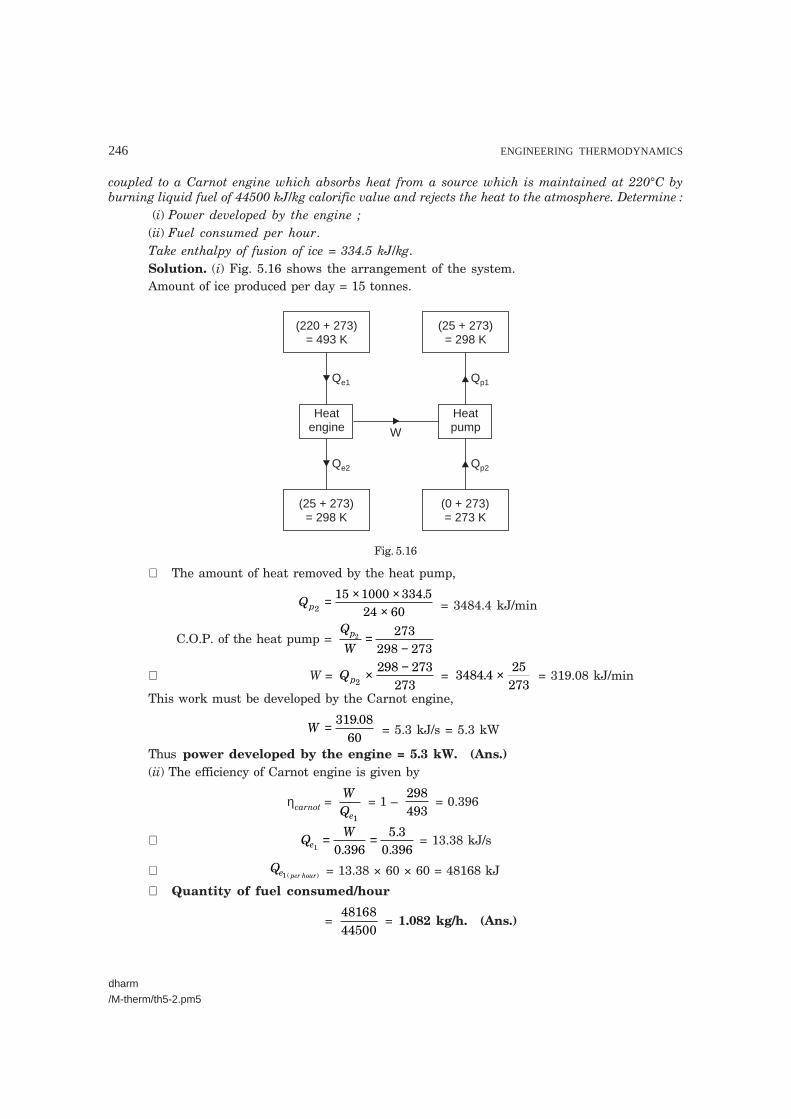
coupled to a Carnot engine which absorbs heat from a source which is maintained at 220°C byburning liquid fuel of 44500 kJ/kg calorific value and rejects the heat to the atmosphere. Determine :
(i) Power developed by the engine ;(ii) Fuel consumed per hour.Take enthalpy of fusion of ice = 334.5 kJ/kg.Solution. (i) Fig. 5.16 shows the arrangement of the system.Amount of ice produced per day = 15 tonnes.
(220 + 273)= 493 K
(25 + 273)= 298 K
(25 + 273)= 298 K
(0 + 273)= 273 K
Heatengine
Heatpump
Qe1 Qp1
Qe2 Qp2
W
Fig. 5.16
∴ The amount of heat removed by the heat pump,
Qp2
15 1000 334 524 60
= × ××
. = 3484.4 kJ/min
C.O.P. of the heat pump = Q
Wp2 273
298 273=
−
∴ W = Qp2
298 273273
× − = 3484 4
25273
. × = 319.08 kJ/min
This work must be developed by the Carnot engine,
W = 319 0860
. = 5.3 kJ/s = 5.3 kW
Thus power developed by the engine = 5.3 kW. (Ans.)(ii) The efficiency of Carnot engine is given by
ηcarnot = WQe1
= 1 – 298493
= 0.396
∴ QW
e1 3963
396= =
0.5.
0. = 13.38 kJ/s
∴ Qe per hour1 ( ) = 13.38 × 60 × 60 = 48168 kJ
∴ Quantity of fuel consumed/hour
= 4816844500
= 1.082 kg/h. (Ans.)

SECOND LAW OF THERMODYNAMICS AND ENTROPY 247
dharm/M-therm/th5-2.pm5
Example 5.15. Two Carnot engines work in series between the source and sink tempera-tures of 550 K and 350 K. If both engines develop equal power determine the intermediate tem-perature.
Solution. Fig. 5.17 shows the arrangement of the system.Temperature of the source, T1 = 550 KTemperature of the sink, T3 = 350 KIntermediate temperature, T2 :The efficiencies of the engines HE1 and HE2 are given by
η1 = WQ1
= T T
T1 2
1
− =
WQ W2 +
...(i)
η2 = WQ2
= T T
T2 3
2
− =
WQ W3 + ...(ii)
From eqn. (i), we get
W = (Q2 + W) T T
T1 2
1
−�
���
��
∴ WT T
T1 1 2
1− −�
���
���
�
���
= QT T
T21 2
1
−�
���
��
∴ WTT
2
1
�
���
�� = Q
T TT2
1 2
1
−�
���
��
∴ W = QT T
T21 2
2
−�
���
��...(iii)
From eqn. (ii), we get
W = QT T
T22 3
2
−�
���
��...(iv)
Now from eqns. (iii) and (iv), we getT1 – T2 = T2 – T3
2T2 = T1 + T3 = 550 + 350∴ T2 = 450 KHence intermediate temperature = 450 K. (Ans.)Example 5.16. A Carnot heat engine draws heat from a reservoir at temperature T1 and
rejects heat to another reservoir at temperature T3. The Carnot forward cycle engine drives aCarnot reversed cycle engine or Carnot refrigerator which absorbs heat from reservoir at tem-perature T2 and rejects heat to a reservoir at temperature T3. If the high temperature T1 = 600 Kand low temperature T2 = 300 K, determine :
(i) The temperature T3 such that heat supplied to engine Q1 is equal to the heat absorbedby refrigerator Q2.
(ii) The efficiency of Carnot engine and C.O.P. of Carnot refrigerator.Solution. Refer Fig. 5.18.Temperature, T1 = 600 KTemperature, T2 = 300 K
Fig. 5.17

248 ENGINEERING THERMODYNAMICS
dharm
/M-therm/th5-2.pm5
T(300 K)
2 T(600 K)
1
Carnotrefrig.
Carnotengine
T3
Q1″ Q1′
W = Q – Qcarnot 11 ′
Q2 Q1
Fig. 5.18
Efficiency of Carnot engine,
ηcarnot engine = Q Q
Q1 1
1
− ′ =
T TT
1 3
1
−
= Work of Carnot engineHeat supplied to the Carnot engine
= W
Qcarnot
1
or W QT T
Tcarnot = −�
���
��11 3
1...(i)
Also C.O.P.(carnot refrigerator) = Q
Q Q2
1 2″ − = T
T T2
3 2−
= =Heat absorbedW
Q
Wcarnot carnot
2
or Wcarnot = QT T
T23 2
2
−�
���
��...(ii)
(i) Temperature, T3 :From eqns. (i) and (ii), we get
QT T
T11 3
1
−�
���
�� = Q
T TT2
3 2
2
−�
���
��
TT
T TT T
2
1
2
1
1 3
3 2= −
−�
���
��
orQQ
2
1 = 1 =
300600
600300
3
3
−−
�
���
��T
Tor 600 – T3 = 2(T3 – 300)
600 – T3 = 2T3 – 600 or T3 = 400 KHence, temperature, T3 = 400 K. (Ans.)

SECOND LAW OF THERMODYNAMICS AND ENTROPY 249
dharm/M-therm/th5-2.pm5
(ii) Efficiency of Carnot engine,
ηcarnot engine = T T
T1 3
1
− =
600 400600−
= 0.3333 = 33.33%. (Ans.)
C.O.P.refrigerator = T
T T2
3 2− =
300400 300−
= 3. (Ans.)
Example 5.17. A heat pump working on a reversed carnot cycle takes in energy from areservoir maintained at 5°C and delivers it to another reservoir where temperature is 77°C. Theheat pump derives power for its operation from a reversible engine operating within the higherand lower temperatures of 1077°C and 77°C. For 100 kJ/kg of energy supplied to reservoir at77°C, estimate the energy taken from the reservoir at 1077°C. (U.P.S.C., 1994)
Solution. Given : T3 = 5 + 273 = 278 K ; T2 = T4 = 77 + 273 = 350 K ;T1 = 273 + 1077 = 1350 K ;
Energy taken from the revervoir at 1077°C, Q1 :
T = T350 K2 4
Pump Engine T = 1350 K1
T = 278 K3
Q4
Q3
Q1
Q2
Fig. 5.19
For reversible engine, η = Q Q
Q1 2
1
− =
T TT
1 2
1
−...(i)
or 1 2
1−
= 1 2
1−
TT
TT
1
2
1
2=
For reversible heat pump, C.O.P. = Q
Q QT
T T4
4 3
4
4 3−=
−...(ii)
Since work for running the pump is being supplied by the engine∴ Q1 – Q2 = Q4 – Q3
orQT
T TQT
T T1
11 2
4
44 3( ) ( )− = − [From (i) and (ii)]

250 ENGINEERING THERMODYNAMICS
dharm
/M-therm/th5-2.pm5
1
4 =
TT
T TT T
1
4
4 3
1 2
−−
�
���
��
= −−
���
���
1350350
350 2781350 350
= 0.278
or Q4 = Q1
0 278. = 3.6 Q1
and Q2 =TT
Q2
11× =
3501350 1Q = 0.259 Q1
∴ Q4 + Q2 = (3.6 + 0.259) Q1 = 100
∴ Q1 = 100
3 6 0 259. .+ = 25.9 kJ. (Ans.)
CLAUSIUS INEQUALITY
�Example 5.18. 300 kJ/s of heat is supplied at a constant fixed temperature of 290°C to aheat engine. The heat rejection takes place at 8.5°C. The following results were obtained :
(i) 215 kJ/s are rejected.(ii) 150 kJ/s are rejected.
(iii) 75 kJ/s are rejected.Classify which of the result report a reversible cycle or irreversible cycle or impossible
results.Solution. Heat supplied at 290°C = 300 kJ/sHeat rejected at 8.5°C : (i) 215 kJ/s, (ii) 150 kJ/s, (iii) 75 kJ/s.Applying Clausius inequality to the cycle or process, we have :
(i)δQT
cycle∑ =
+−
+300
290 273215
85 273.= 0.5328 – 0.7637 = – 0.2309 < 0.
∴ Cycle is irreversible. (Ans.)
(ii)δQT
cycle∑ =
+−
+300
290 273150
8 5 273.
= 0.5328 – 0.5328 = 0∴ Cycle is reversible. (Ans.)
(iii)δQT
cycle8.∑ =
+−
+300
290 27375
5 273
= 0.5328 – 0.2664 = 0.2664 > 0.This cycle is impossible by second law of thermodynamics, i.e., Clausius inequality. (Ans.)Example 5.19. A steam power plant operates between boiler temperature of 160°C and
condenser temperature of 50°C. Water enters the boiler as saturated liquid and steam leaves theboiler as saturated vapour. Verify the Clausius inequality for the cycle.
Given : Enthalpy of water entering boiler = 687 kJ/kg.Enthalpy of steam leaving boiler = 2760 kJ/kgCondenser pressure = 0.124 × 10⁵ N/m2.
SECOND LAW OF THERMODYNAMICS AND ENTROPY 251
dharm/M-therm/th5-2.pm5
Solution. Boiler temperature, T1 = 160 + 273 = 433 KCondenser temperature, T2 = 50 + 273 = 323 KFrom steam tables :
Enthalpy of water entering boiler, hf1 = 687 kJ/kg
Enthalpy of steam leaving boiler, h2 = 2760 kJ/kgCondenser pressure = 0.124 × 10⁵ N/m2
Boiler pressure = 6.18 × 10⁵ N/m2 ......(corresponding to 160°C)Enthalpy of vapour leaving the turbine, h3 = 2160 kJ/kg(assuming isentropic expansion)
Enthalpy of water leaving the condenser, hf4 = 209 kJ/kg
Now Qboiler, Q1 = h2 – hf1 = 2760 – 687 = 2073 kJ/kg
and Qcondenser, Q2 = hf4 – h3 = 209 – 2160 = – 1951 kJ/kg
∴δQT
QT
QT
cycle∑ = + = + −�
�����
1
1
2
2
2073433
1951323
= – 1.25 kJ/kg K< 0. ...... Proved.
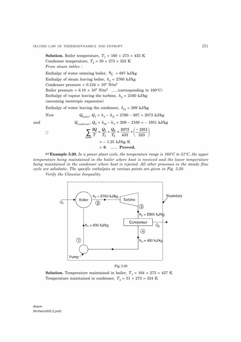
�Example 5.20. In a power plant cycle, the temperature range is 164°C to 51°C, the uppertemperature being maintained in the boiler where heat is received and the lower temperaturebeing maintained in the condenser where heat is rejected. All other processes in the steady flowcycle are adiabatic. The specific enthalpies at various points are given in Fig. 5.20.
Verify the Clausius Inequality.
Fig. 5.20
Solution. Temperature maintained in boiler, T1 = 164 + 273 = 437 KTemperature maintained in condenser, T2 = 51 + 273 = 324 K
252 ENGINEERING THERMODYNAMICS
dharm/M-therm/th5-3.pm5
Heat transferred in the boiler per kg of fluid,Q1 = h2 – h1 = 2760 – 690 = 2070 kJ/kg
Heat transferred out at the condenser per kg of fluid,Q2 = h4 – h3 = 450 – 2360 = – 1910 kJ/kg
Since there is no transfer of heat at any other point, we have per kg
δQT
QT
QT
cycle∑ = + = + −�
�����
1
1
2
2
2070437
1910324
= 4.737 – 5.895= – 1.158 kJ/kg K < 0.
The Clausius Inequality is proved. The steady flow cycle is obviously irreversible.If the cycle is reversible between the same temperature limits and the heat supplied at
higher temperature is same, the heat rejected can be calculated as follows :
ηreversible = 1 – TT
2
1 = 1 – 324
437 = 0.2586 or 25.86%
∴ Heat rejected per kg is given byQ2 = (1 – 0.2586) × Q1 = (1 – 0.2586) × 2070 = 1534.7 kJ/kg
δQT
cycle∑ = −2070
4371534 7
324.
= 4.73 – 4.73 = 0
i.e.,δQT
QT
Q
Tadded
source
rejected
cycle∑ = =
sink = 0
Thus Clausius Equality sign for a reversible engine is verified.
5.12. ENTROPY
5.12.1. IntroductionIn heat engine theory, the term entropy plays a vital role and leads to important results
which by other methods can be obtained much more laboriously.It may be noted that all heat is not equally valuable for converting into work. Heat that is
supplied to a substance at high temperature has a greater possibility of conversion into work thanheat supplied to a substance at a lower temperature.
“Entropy is a function of a quantity of heat which shows the possibility of conversion ofthat heat into work. The increase in entropy is small when heat is added at a high temperatureand is greater when heat addition is made at a lower temperature. Thus for maximum entropy,there is minimum availability for conversion into work and for minimum entropy there is maxi-mum availability for conversion into work.”
5.12.2. Entropy—a Property of a System
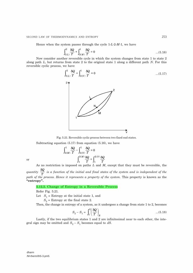
Refer Fig. 5.21. Let us consider a system undergoing a reversible process from state 1 tostate 2 along path L and then from state 2 to the original state 1 along path M. Applying theClausius theorem to this reversible cyclic process, we have
δQTR
= 0
(where the subscript designates a reversible cycle)
SECOND LAW OF THERMODYNAMICS AND ENTROPY 253
dharm/M-therm/th5-3.pm5
Hence when the system passes through the cycle 1-L-2-M-1, we have
δ δQT
QTL M1
2
2
10
( ) ( ) + = ...(5.16)
Now consider another reversible cycle in which the system changes from state 1 to state 2along path L, but returns from state 2 to the original state 1 along a different path N. For thisreversible cyclic process, we have
δ δQT
QTL N1
2
2
10
( ) ( ) + = ...(5.17)
Fig. 5.21. Reversible cyclic process between two fixed end states.
Subtracting equation (5.17) from equation (5.16), we have
δ δQT
QTM N2
1
2
10
( ) ( ) − =
orδ δQT
QT
M N
1
2
1
2( ) ( )
=
As no restriction is imposed on paths L and M, except that they must be reversible, the
quantity δQT
is a function of the initial and final states of the system and is independent of the
path of the process. Hence it represents a property of the system. This property is known as the“entropy”.
5.12.3. Change of Entropy in a Reversible ProcessRefer Fig. 5.21.Let S1 = Entropy at the initial state 1, and
S2 = Entropy at the final state 2.Then, the change in entropy of a system, as it undergoes a change from state 1 to 2, becomes
S2 – S1 = δQT R
������ 1
2...(5.18)
Lastly, if the two equilibrium states 1 and 2 are infinitesimal near to each other, the inte-gral sign may be omitted and S2 – S1 becomes equal to dS.

254 ENGINEERING THERMODYNAMICS
dharm/M-therm/th5-3.pm5
Hence equation (5.18) may be written as
dS = δQT R
������ ...(5.19)
where dS is an exact differential.Thus, from equation (5.19), we find that the change of entropy in a reversible process is
equal to δQT
. This is the mathematical formulation of the second law of thermodynamics.
Equation (5.19) indicates that when an inexact differential δQ is divided by an integratingfactor T during a reversible process, it becomes an exact differential.
The third law of thermodynamics states “When a system is at zero absolute tempera-ture, the entropy of system is zero”.
It is clear from the above law that the absolute value of entropy corresponding to a given
state of the system could be determined by integrating δQT R
������
between the state at absolute zero
and the given state. Zero entropy, however, means the absence of all molecular, atomic, elec-tronic and nuclear disorders.
As it is not practicable to get data at zero absolute temperature, the change in entropy iscalculated either between two known states or by selecting some convenient point at which theentropy is given an arbitrary value of zero. For steam, the reference point at which the entropy isgiven an arbitrary value of zero is 0°C and for refrigerants like ammonia, Freon-12, carbon dioxideetc. the reference point is – 40°C, at which the entropy it taken as zero.
Thus, in practice we can determine the change in entropy and not the absolute value ofentropy.
5.13. ENTROPY AND IRREVERSIBILITY
We know that change in entropy in a reversible process is equal to δQT R
������
(eqn. 5.19). Let
us now find the change in entropy in an irreversible process.
p2
L
M
1
V
Fig. 5.22. Entropy change for an irreversible process.
Consider a closed system undergoing a change from state 1 to state 2 by a reversible process1-L-2 and returns from state 2 to the initial state 1 by an irreversible process 2-M-1 as shown inFig. 5.22 on the thermodynamic coordinates, pressure and volume.

SECOND LAW OF THERMODYNAMICS AND ENTROPY 255
dharm/M-therm/th5-3.pm5
Since entropy is a thermodynamic property, we can write
dS dS dSR IML = + =( ) ( )
( )( ) 2
1
1
20 ...(5.20)
(Subscript I represents the irreversible process).Now for a reversible process, from eqn. (5.19), we have
( )( ) ( )
dSQTR
L RL1
2
1
2
= ������
δ...(5.21)
Substituting the value of ( )( )
dS RL1
2
in eqn. (5.20), we get
δQT
dSR
IML
������
+ = ( )( )( ) 2
1
1
20 ...(5.22)
Again, since in eqn. (5.20) the processes 1-L-2 and 2-M-1 together form an irreversible cycle,applying Clausius equality to this expression, we get
δ δ δQT
QT
QTR IML = �
�����
+ ������2
1
1
2
( )( ) < 0 ...(5.23)
Now subtracting eqn. (5.23) from eqn. (5.22), we get
( )( ) ( )
dSQTI
M M I2
1
2
1
> ������
δ
which for infinitesimal changes in states can be written as
( )dSQTI
I> ������ δ
...(5.24)
Eqn. (5.24) states that the change in entropy in an irreversible process is greater than δQT
.
Combining eqns. (5.23) and (5.24), we can write the equation in the general form as
dS ≥ δQT
...(5.25)
where equality sign stands for the reversible process and inequality sign stands for the irrevers-ible process.
It may be noted here that the effect of irreversibility is always to increase the entropy of thesystem.
Let us now consider an isolated system. We know that in an isolated system, matter, workor heat cannot cross the boundary of the system. Hence according to first law of thermodynamics,the internal energy of the system will remain constant.
Since for an isolated system, δQ = 0, from eqn. (5.25), we get(dS)isolated ≥ 0 ...(5.26)
Eqn. (5.26) states that the entropy of an isolated system either increases or remains con-stant. This is a corollary of the second law. It explains the principle of increase in entropy.
5.14. CHANGE IN ENTROPY OF THE UNIVERSE
We know that the entropy of an isolated system either increase or remains constant, i.e.,
(dS)isolated _≥ 0

256 ENGINEERING THERMODYNAMICS
dharm/M-therm/th5-3.pm5
By including any system and its surrounding within a single boundary, as shown inFig. 5.23, an isolated system can be formed. The combination of the system and the surroundingswithin a single boundary is sometimes called the Universe. Hence, applying the principle ofincrease in entropy, we get
(dS)universe _≥ 0where (dS)universe = (dS)system + (dS)surroundings.
Systemtemperature
Surroundingtemperature
T0
Boundary ofthe universe
Fig. 5.23. Entropy change of universe.
In the combined closed system consider that a quantity of heat δQ is transferred from thesystem at temperature T to the surroundings at temperature T0. Applying eqn. (5.24) to thisprocess, we can write
(dS)system > – δQT
(–ve sign indicates that heat is transferred from the system).Similarly, since an amount of heat δQ is absorbed by the surroundings, for a reversible
process, we can write
(dS)surroundings = δQT0
Hence, the total change in entropy for the combined system
(dS)system + (dS)surroundings ≥ – δ δQT
QT
+0
or (dS)universe ≥ dQ − +�
���
��1 1
0T T
The same result can be obtained in the case of an open system.For both closed and open systems, we can write
(dS)universe ≥ 0 ...(5.27)Eqn. (5.27) states that the process involving the interaction of a system and the surround-
ings takes place only if the net entropy of the combined system increases or in the limit remainsconstant. Since all natural processes are irreversible, the entropy is increasing continually.

SECOND LAW OF THERMODYNAMICS AND ENTROPY 257
dharm/M-therm/th5-3.pm5
The entropy attains its maximum value when the system reaches a stable equilibriumstate from a non-equilibrium state. This is the state of maximum disorder and is one of maximumthermodynamic probability.
5.15. TEMPERATURE-ENTROPY DIAGRAM
If entropy is plotted-horizontally and absolute temperature vertically the diagram so obtainedis called temperature-entropy (T-s) diagram. Such a diagram is shown in Fig. 5.24. If workingfluid receives a small amount of heat dQ in an elementary portion ab of an operation AB whentemperature is T, and if dQ is represented by the shaded area of which T is the mean ordinate, the
width of the figure must be dQT
. This is called ‘increment of entropy’ and is denoted by dS. The
total heat received by the operation will be given by the area under the curve AB and (SB – SA) willbe corresponding increase of entropy.
dS SBSAS (Entropy)
A
ab
B
T (Temp.)
Fig. 5.24. Temperature-entropy diagram.
From above we conclude that :
Entropy change, dSQ
T= Heat change ( )
Absolute temperature ( ) .
“Entropy may also be defined as the thermal property of a substance which remainsconstant when substance is expanded or compressed adiabatically in a cylinder”.
Note. ‘s’ stands for specific entropy whereas ‘S’ means total entropy (i.e., S = ms).
5.16. CHARACTERISTICS OF ENTROPY
The characteristics of entropy in a summarised form are given below :1. It increases when heat is supplied irrespective of the fact whether temperature changes
or not.2. It decrease when heat is removed whether temperature changes or not.

258 ENGINEERING THERMODYNAMICS
dharm/M-therm/th5-3.pm5
3. It remains unchanged in all adiabatic frictionless processes.4. It increases if temperature of heat is lowered without work being done as in a throttling
process.
5.17. ENTROPY CHANGES FOR A CLOSED SYSTEM
5.17.1. General Case for Change of Entropy of a GasLet 1 kg of gas at a pressure p1, volume v1, absolute temperature T1 and entropy s1, be
heated such that its final pressure, volume, absolute temperature and entropy are p2, v2, T2 and s2respectively. Then by law of conservation of energy,
dQ = du + dWwhere, dQ = Small change of heat,
du = Small internal energy, and dW = Small change of work done (pdv).
Now dQ = cvdT + pdvDividing both sides by T, we get
dQT
c dTT
pdvT
v= +
ButdQT
= ds
and as pv = RT
∴pT
Rv
=
Hence dsc dT
TR
dvv
v= +
Integrating both sides, we get
ds cdTT
Rdvvs
s
vT
T
v
v
1
2
1
2
1
2
= +
or (s2 – s1) = cv loge TT
2
1 + R loge
vv
2
1...(5.28)
This expression can be reproduced in the following way :According to the gas equation, we have
p vT
p vT
1 1
1
2 2
2=
or TT
pp
vv
2
1
2
1
2
1= ×
Substituting the value of TT
2
1 in eqn. (5.28), we get
s2 – s1 = cv loge pp
vv
2
1
2
1× + R loge
vv
2
1
= cv loge pp
2
1 + cv loge
vv
2
1 + R loge
vv
2
1

SECOND LAW OF THERMODYNAMICS AND ENTROPY 259
dharm/M-therm/th5-3.pm5
s1
T1
T2
s2 s
Q
2
v = Const.
T
1
= cv loge pp
2
1 + (cv + R) loge
vv
2
1
= cv loge pp
2
1 + cp loge
vv
2
1
∴ s2 – s1 = cv loge pp
2
1 + cp loge
vv
2
1...(5.29)
Again, from gas equation,
p vT
p vT
1 1
1
2 2
2= or v
vpp
TT
2
1
1
2
2
1= ×
Putting the value of vv
2
1 in eqn. (5.28), we get
(s2 – s1) = cv loge TT
2
1 + R loge
pp
TT
1
2
2
1×
= cv loge TT
2
1 + R loge
pp
1
2 + R loge
TT
2
1
= (cv + R) loge TT
2
1 – R loge
pp
2
1
= cp loge TT
2
1 – R loge
pp
2
1
∴ s2 – s1 = cp loge TT
2
1– R loge
pp
2
1. ...(5.30)
5.17.2. Heating a Gas at Constant VolumeRefer Fig. 5.25. Let 1 kg of gas be heated at
constant volume and let the change in entropy andabsolute temperature be from s1 to s2 and T1 to T2respectively.
Then Q = cv(T2 – T1)Differentiating to find small increment of heat
dQ corresponding to small rise in temperature dT.dQ = cvdT
Dividing both sides by T, we get
dQT
= cv . dTT
or ds = cv . dTT
Integrating both sides, we get
ds cdTTs
s
vT
T
1
2
1
2
=
or s2 – s1 = cv loge TT
2
1...(5.31) Fig. 5.25. T-s diagram : Constant
volume process
260 ENGINEERING THERMODYNAMICS
dharm/M-therm/th5-3.pm5
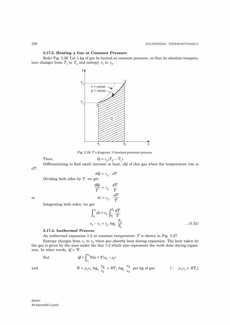
5.17.3. Heating a Gas at Constant PressureRefer Fig. 5.26. Let 1 kg of gas be heated at constant pressure, so that its absolute tempera-
ture changes from T1 to T2 and entropy s1 to s2.
s1
T1
T2
s2 s
Q
2
1
T
v = const.p = const.
Fig. 5.26. T-s diagram : Constant pressure process.
Then, Q = cp(T2 – T1).Differentiating to find small increase in heat, dQ of this gas when the temperature rise is
dT.dQ = cp . dT
Dividing both sides by T, we get
dQT
= cp . dTT
or ds = cp . dTT
Integrating both sides, we get
ds cdTTs
s
pT
T
1
2
1
2
=
s2 – s1 = cp loge TT
2
1...(5.32)
5.17.4. Isothermal ProcessAn isothermal expansion 1-2 at constant temperature T is shown in Fig. 5.27.Entropy changes from s1 to s2 when gas absorbs heat during expansion. The heat taken by
the gas is given by the area under the line 1-2 which also represents the work done during expan-sion. In other words, Q = W.
But Q Tds T s ss
s= = −
1
2
2 1( )
and W = p1v1 loge vv
2
1 = RT1 loge
vv
2
1 per kg of gas [� p1v1 = RT1]

SECOND LAW OF THERMODYNAMICS AND ENTROPY 261
dharm/M-therm/th5-3.pm5
Fig. 5.27. T-s diagram : Isothermal process.
∴ T(s2 – s1) = RT1 loge vv
2
1
or s2 – s1 = R loge vv
2
1. [� T1 = T2 = T] ...(5.33)
5.17.5. Adiabatic Process (Reversible)During an adiabatic process as heat is neither supplied nor rejected,
dQ = 0
ordQdT
= 0
or ds = 0 ...(5.34)
Fig. 5.28. T-s diagram : Adiabatic process.
This shows that there is no change in entropy and hence it is known as isentropic process.Fig. 5.28 represents an adiabatic process. It is a vertical line (1-2) and therefore area under
this line is nil ; hence heat supplied or rejected and entropy change is zero.

262 ENGINEERING THERMODYNAMICS
dharm/M-therm/th5-3.pm5
5.17.6. Polytropic ProcessRefer Fig. 5.29.The expression for ‘entropy change’ in polytropic process (pvn = constant) can be obtained
from eqn. (5.28)
i.e., s2 – s1 = cv loge TT
2
1 + R loge
vv
2
1
Fig. 5.29. T-s diagram : Polytropic process.
Also p1v1n = p2v2
n
or pp
vv
n1
2
2
1=�
���
��...(i)
Again, asp vT1 1
1 =
p vT2 2
2
orpp
1
2 =
vv
TT
2
1
1
2× ...(ii)
From (i) and (ii), we get
vv
n2
1
�
���
�� =
vv
TT
2
1
1
2×
orvv
n2
1
1�
���
��
−
= TT
1
2
orvv
2
1 =
TT
n1
2
11�
���
��−
Substituting the value of vv
2
1 in eqn. (5.28), we get
s2 – s1 = cv loge TT
2
1+ R loge
TT
n1
2
11�
���
��−
= cv loge TT
2
1 + R
11n −
���
���
loge TT
1
2

SECOND LAW OF THERMODYNAMICS AND ENTROPY 263
dharm/M-therm/th5-3.pm5
= cv loge TT
2
1 – R
11n −
���
���
loge TT
2
1
= cv loge TT
2
1 – (cp – cv) × 1
1n −���
���
loge TT
2
1[� R = cp – cv]
= cv loge TT
2
1 – (γ . cv – cv) ×
11n −
���
���
loge TT
2
1[� cp= γ . cv]
= −−−
���
���
�
�
���
cnv 1
11
γ loge
TT
2
1 = − − −
−�
�
��c
nnv
( ) ( )( )1 1
1γ
loge TT
2
1
= − − +−
���
���
cn
nv1 1
1γ ) loge
TT
2
1
= cv . nn
−−
���
���
γ1
loge TT
2
1 per kg of gas
∴ s2 – s1 = cv nn
−−
���
���
γ1
loge TT
2
1 per kg of gas ...(5.35)
5.17.7. Approximation For Heat AbsorbedThe curve LM shown in the Fig. 5.30 is obtained by heating 1 kg of gas from initial state L
to final state M. Let temperature during heating increases from T1 to T2. Then heat absorbed bythe gas will be given by the area (shown shaded) under curve LM.
s1
T1
T2
s2 s
Q
M
T
L
Fig. 5.30
As the curve on T-s diagram which represents the heating of the gas, usually has veryslight curvature, it can be assumed a straight line for a small temperature range. Then,
Heat absorbed = Area under the curve LM
= (s2 – s1) T T1 2
2+�
�����
...(5.36)

264 ENGINEERING THERMODYNAMICS
dharm/M-therm/th5-3.pm5
In other words, heat absorbed approximately equals the product of change of entropy andmean absolute temperature.
Table 5.1. Summary of Formulae
S. No. Process Change of entropy (per kg)
1. General case (i) cv loge TT
2
1 + R loge
vv2
1 (in terms of T and v)
(ii) cv loge pp
2
1 + cv loge
vv2
1 (in terms of p and v)
(iii) cp loge TT
2
1 – R loge
pp
2
1 (in terms of T and p)
2. Constant volume cv loge TT
2
1
3. Constant pressure cp loge TT
2
1
4. Isothermal R loge vv2
1
5. Adiabatic Zero
6. Polytropic cv nn
−−
�
���
��γ1
loge TT
2
1
5.18. ENTROPY CHANGES FOR AN OPEN SYSTEM
In an open system, as compared with closed system, there is additional change of entropydue to the mass crossing the boundaries of the system. The net change of entropy of a system dueto mass transport is equal to the difference between the product of the mass and its specificentropy at the inlet and at the outlet of the system. Therefore, the total change of entropy of thesystem during a small interval is given by
dS ≥ dQT0
+ Σsi . dm si
− Σ0 . dm0
where, T0 = Temperature of the surroundings,si = Specific entropy at the inlet,
s0 = Specific entropy at the outlet,dmi = Mass entering the system, anddm0 = Mass leaving the system.
(Subscripts i and 0 refer to inlet and outlet conditions)The above equation in general form can be written as
dS ≥ dQT0
+ s dm.∑ ...(5.37)
In equation (5.37) entropy flow into the system is considered positive and entropy out-flowis considered negative. The equality sign is applicable to reversible process in which the heatinteractions and mass transport to and from the system is accomplished reversibly. The inequalitysign is applicable to irreversible processes.
SECOND LAW OF THERMODYNAMICS AND ENTROPY 265
dharm/M-therm/th5-3.pm5
If equation (5.37) is divided by dt, then it becomes a rate equation and is written as
dSdt
≥ 1
0TdQdt
. + sdmdt
.∑ ...(5.38)
In a steady-state, steady flow process, the rate of change of entropy of the system dSdt����
becomes zero.
∴ O ≥ 1
0TdQdt
+ sdmdt
.∑or
1
0TQ.
+ Σs . �m ≤ 0 ...(5.39)
where Q.
= dQdt
and �m = dmdt
.
For adiabatic steady flow process, Q.
= 0
s m. �∑ ≤ 0 ...(5.40)
If the process is reversible adiabatic, then
s m. �∑ = 0 ...(5.41)
5.19. THE THIRD LAW OF THERMODYNAMICS
� The third law of thermodynamics is stated as follow :‘‘The entropy of all perfect crystalline solids is zero at absolute zero temperature’’.
� The third law of thermodynamics, often referred to as Nernst Law, provides the basisfor the calculation of absolute entropies of substances.
According to this law, if the entropy is zero at T = 0, the absolute entropy sab. of a substanceat any temperature T and pressure p is expressed by the expression.
s cdTT
h
Tc
dTT
h
Tab ps
T T sf
spf
T
T T fg
g
s f
s
f g= + + +
= =
0
1 2 c
dTTpg
T
T
g ...(5.42)
where Ts = Tf 1 = Tsf = Tsat ...... for fusion,Tf 2 = Tg = Tfg = Tsat ......for vaporisation
cps, cpf , cpg = Constant pressure specific heats for solids, liquids and gas,hsf , hfg = Latent heats of fusion and vaporisation.
Thus by putting s = 0 at T = 0, one may integrate zero kelvin and standard state of 278.15 Kand 1 atm., and find the entropy difference.
� Further, it can be shown that the entropy of a crystalline substance at T = 0 is not afunction of pressure, viz.,
∂∂
sp T
������
== 0
0

266 ENGINEERING THERMODYNAMICS
dharm/M-therm/th5-3.pm5
However, at temperatures above absolute zero, the entropy is a function of pressure also.The absolute entropy of a substance at 1 atm pressure can be calculated using eqn. (5.42) ; forpressures different from 1 atm, necessary corrections have to be applied.
ENTROPY
Exmaple 5.21. An iron cube at a temperature of 400°C is dropped into an insulated bathcontaining 10 kg water at 25°C. The water finally reaches a temperature of 50°C at steady state.Given that the specific heat of water is equal to 4186 J/kg K. Find the entropy changes for theiron cube and the water. Is the process reversible ? If so why ? (GATE, 1996)
Solution. Given : Temperature of iron cube = 400°C = 673 KTemperature of water = 25°C = 298 KMass of water = 10 kgTemperature of water and cube after equilibrium = 50°C = 323 KSpecific heat of water, cpw = 4186 J/kg KEntropy changes for the iron cube and the water :Is the process reversible ?Now, Heat lost by iron cube = Heat gained by water
mi cpi (673 – 323) = mw cpw (323 – 298)= 10 × 4186 (323 – 298)
∴ mi cpi = 10 4186 323 298
623 323× −
−( )
( ) = 2990
where, mi = Mass of iron, kg, andcpi = Specific heat of iron, J/kg K
Entropy of iron at 673 K = mi cpi ln 673273���
���
= 2990 ln 673273���
���
= 2697.8 J/K [Taking 0°C as datum]
Entropy of water at 298 K = mw cpw ln 298273���
���
= 10 × 4186 ln 298273���
��� = 3667.8 J/K
Entropy of iron at 323 K = 2990 × ln 323273���
��� = 502.8 J/K
Entropy water at 323 K = 10 × 4186 ln 323273���
��� = 7040.04 J/K
Changes in entropy of iron = 502.8 – 2697.8 = – 2195 J/KChange in entropy of water = 7040.04 – 3667.8 = 3372.24 J/KNet change in entropy = 3372.24 – 2195 = 1177.24 J/KSince ∆S > 0 hence the process is irrevesible. (Ans.)Example 5.22. An ideal gas is heated from temperature T1 to T2 by keeping its volume
constant. The gas is expanded back to its initial temperature according to the law pvn = constant.If the entropy change in the two processes are equal, find the value of n in terms of the adiabaticindex γ. (U.P.S.C., 1997)

SECOND LAW OF THERMODYNAMICS AND ENTROPY 267
dharm/M-therm/th5-3.pm5
Solution. Change in entropy during constant volume process
= m cv ln TT
2
1
�
���
��...(i)
Change in entropy during polytropic process (pvn = constant)
= m cv γ −
−���
���
nn 1
ln TT
2
1
�
���
��...(ii)
For the same entropy, equating (i) and (ii), we have
γ −−
nn 1 = 1, or (γ – n) = (n – 1) or 2n = γ + 1
∴ n = γ +12 . (Ans).
Example 5.23. Air at 20°C and 1.05 bar occupies 0.025 m3. The air is heated at constantvolume until the pressure is 4.5 bar, and then cooled at constant pressure back to original tem-perature. Calculate :
(i) The net heat flow from the air.(ii) The net entropy change.Sketch the process on T-s diagram.Solution. The processes are shown on a T-s diagram in Fig. 5.31.
Fig. 5.31
For air :Temperature, T1 = 20 + 273 = 293 KVolume, V1 = V3 = 0.025 m3
Pressure, p1 = 1.05 bar = 1.05 × 10⁵ N/m2
Pressure, p2 = 4.5 bar = 4.5 × 10⁵ N/m2.(i) Net heat flow :
For a perfect gas (corresponding to point 1 of air),
m = p VRT
1 1
1=
105 10 0 025
0 287 10 293
5
3. .
.
× ×× ×
= 0.0312 kg

268 ENGINEERING THERMODYNAMICS
dharm/M-therm/th5-3.pm5
For a perfect gas at constant volume,pT
pT
1
1
2
2=
1. 4.05293
5
2=
Tor T2
4 5 293105
= ×..
= 1255.7 K.
At constant volume,Q = mcv (T2 – T1) = 0.0312 × 0.718 (1255.7 – 293)
i.e., Q1–2 = 21.56 kJ.Also, at constant pressure,
Q = m × cp × (T3 – T2) = 0.0312 × 1.005 (293 – 1255.7)i.e., Q2–3 = – 30.18 kJ
∴ Net heat flow = Q1–2 + Q2–3 = 21.56 + (– 30.18) = – 8.62 kJi.e., Heat rejected = 8.62 kJ. (Ans.)
(ii) Net entropy change :Referring to Fig. 5.31.Net decrease in entropy,
S1 – S2 = (S2 – S3) – (S2 – S1)At constant pressure, dQ = mcp dT, hence
m(s2 – s3) = mc dT
Tp
293
1255 7.
= 0.0312 × 1.005 × loge
12557293
.
i.e., S2 – S3 = 0.0456 kJ/KAt constant volume, dQ = mcv dT, hence
m(s2 – s1) = mc dTTv
293
1255 7.
= 0.0312 × 0.718 × loge
1255 7293
. = 0.0326 kJ/K
i.e., S2 – S1 = 0.0326 kJ/K∴ m(s1 – s3) = S1 – S3 = (S2 – S3) – (S2 – S1)
= 0.0456 – 0.0326 = 0.013 kJ/KHence, decrease in entropy = 0.013 kJ/K. (Ans.)Note that since entropy is a property, the decrease in entropy is given by S1 – S3, is inde-
pendent of the process undergone between states 1 and 3.
Example 5.24. 0.04 m3 of nitrogen contained in a cylinder behind a piston is initially at1.05 bar and 15°C. The gas is compressed isothermally and reversibly until the pressure is4.8 bar. Calculate :
(i) The change of entropy,(ii) The heat flow, and
(iii) The work done.Sketch the process on a p-v and T-s diagram.Assume nitrogen to act as a perfect gas. Molecular weight of nitrogen = 28.

SECOND LAW OF THERMODYNAMICS AND ENTROPY 269
dharm/M-therm/th5-3.pm5
Solution. Refer Fig. 5.32.Initial pressure, p1 = 1.05 bar = 1.05 × 10⁵ N/m2
Initial volume, V1 = 0.04 m3
Temperature, T1 = 15 + 273 = 288 KFinal pressure, p2 = 4.8 bar = 4.8 × 10⁵ N/m2
Final temperature, T2 = T1 = 288 K.The process is shown on a p-v and a T-s diagram in Figs. 5.32 (a) and 5.32 (b) respectively.
The shaded area in Fig. 5.32 (a) represents work input, and the shaded area on Fig. 5.32 (b)represents heat rejected.
Characteristic gas constant,
RR
M= Universal gas constant,
Molecular weight,0 =
831428
= 297 Nm/kg K
(a)
(b)Fig. 5.32

270 ENGINEERING THERMODYNAMICS
dharm/M-therm/th5-3.pm5
Now, using characteristic gas equation (to find mass ‘m’ of nitrogen), we have :p1V1 = mRT1
mp VRT
= = × ××
1 1
1
51 05 10 0 04297 288
. . = 0.0491 kg
(i) The change of entropy,
S2 – S1 = mR loge pp
1
2
= 0.0491 × 297
103 loge 1054 8..
���
���
i.e., S2 – S1 = – 0.02216 kJ/K.∴ Decrease in entropy, S1 – S2 = 0.02216 kJ/K. (Ans.)(ii) Heat rejected = Shaded area on Fig. 5.32 (b)
= T(S1 – S2) = 288 × 0.02216 = 6.382 kJ. (Ans.)(iii) For an isothermal process for a perfect gas,
W = Q = 6.382 kJHence, the work done on air = 6.382 kJ. (Ans.)Example 5.25. 1 kg of gas enclosed in an isolated box of volume v1, temperature T1 and
pressure p1 is allowed to expand freely till volume increases to v2 = 2v1.Determine the change in entropy.Take R for gas as 287 kJ/kg K.Solution. During the process of free expansion in an isolated box,
∆ U = 0, W = 0 and Q = ∆ U + W = 0The process is represented by dotted line on p-v diagram as shown in Fig. 5.33 (a) where
v2 = 2v1.
(a) (b)
Fig. 5.33
To calculate the entropy change, assume that the irreversible free expansion process isreplaced by a reversible isothermal process as temperature in free expansion remains constant, insuch a way that the volume increases to double of its original as shown in Fig. 5.33 (b). As the workis developed by the system and heat is given to the system at constant temperature, during iso-thermal reversible system then as per first law of thermodynamics :

SECOND LAW OF THERMODYNAMICS AND ENTROPY 271
dharm/M-therm/th5-3.pm5
∆U = 0, Q = W
i.e., Q p dvv
v= .
1
2
=RTv
dvv
v.
1
2
� pv RT pRTv
= =�
�
��and
= RT loge vv
2
1
∴QT
= R loge vv
2
1But this is the expression for change in entropy of the system. Entropy being the property of
the system, its change is same whether it is reversible or irreversible process.∴ For the given process,
∆s = R loge vv
2
1
�
���
��
= 287 loge (2) [� v2 = 2v1 (given)]= 198.9 kJ/kg K
Hence change in entropy = 198.9 kJ/kg K. (Ans.)Example 5.26. 0.04 kg of carbon dioxide (molecular weight = 44) is compressed from 1
bar, 20°C, until the pressure is 9 bar, and the volume is then 0.003 m3. Calculate the change ofentropy.
Take cp for carbon dioxide as 0.88 kJ/kg K, and assume carbon dioxide to be a perfect gas.Solution. Mass of carbon dioxide, m = 0.04 kgMolecular weight, M = 44Initial pressure, p1 = 1 bar = 1 × 10⁵ N/m2
Initial temperature, T1 = 20 + 273 = 293 KFinal pressure, p2 = 9 barFinal volume, V2 = 0.003 m3
cp for carbon dioxide = 0.88 kJ/kg KChange of entropy :
T(K)
T2
T= 293 K
1
s2 s1 sA s (kJ/kg K)
1 barA
0.003 m3
9 bar
2
1
Fig. 5.34

272 ENGINEERING THERMODYNAMICS
dharm/M-therm/th5-3.pm5
Characteristics gas constant,
R = RM
0 = 831444
= 189 Nm/kg K
To find T2, using the relation, p2V2 = mRT2
∴ T2 = p VmR2 2 =
9 10 0 0030 04 189
5× ××
..
= 357 K
Now sA – s2 = R loge pp
2
1 =
189
103 loge 91������
= 0.4153 kJ/kg KAlso at constant pressure from 1 to A
sA – s1 = cp loge TT
2
1 = 0.88 loge
357293���
���
= 0.1738 kJ/kg KThen (s1 – s2) = (sA – s2) – (sA – s1)
= 0.4153 – 0.1738 = 0.2415 kJ/kg KHence for 0.04 kg of carbon dioxide decrease in entropy,
S1 – S2 = m(s1 – s2) = 0.04 × 0.2415= 0.00966 kJ/K. (Ans.)
Note. In short, the change of entropy can be found by using the following relation :
(s2 – s1) = cp loge TT
2
1 – R loge
pp
2
1 = 0.88 loge
357293
189
103���
���
− loge 91������
= 0.1738 – 0.4153 = – 0.2415 kJ/kg K∴ S2 – S1 = m(s2 – s1) = 0.04 × (– 0.2415)
= – 0.00966 kJ/K(– ve sign means decrease in entropy)
or S1 – S2 = 0.00966 kJ/K.
Example 5.27. Calculate the change of entropy of 1 kg of air expanding polytropically in acylinder behind a piston from 7 bar and 600°C to 1.05 bar. The index of expansion is 1.25.
Solution. The process is shown on a T-s diagram in Fig. 5.35.Initial pressure, p1 = 7 bar = 7 × 10⁵ N/m2
Initial temperature, T1 = 600 + 273 = 873 KFinal pressure, p2 = 1.05 bar = 1.05 × 10⁵ N/m2
Index of expansion, n = 1.25Mass of air = 1 kgTo find T2, using the relation,
TT
2
1 = p
p
nn2
1
1�
���
��
−
∴ T2
873 = 1.05
7
1 25 11 25�
�����
−..

SECOND LAW OF THERMODYNAMICS AND ENTROPY 273
dharm/M-therm/th5-4.pm5
Fig. 5.35
or T2 = 873 × 1 057
0 251 25...�
�����
= 873 × (0.15)0.2 = 597.3 K.
Now replace the process 1 to 2 by processes, 1 to A and A to 2.Then at constant temperature from 1 to A,
sA – s1 = R loge vv2
1 = R loge
pp
1
2 = 0.287 loge
7051.
���
���
= 0.544 kJ/kg K.
Fig. 5.36
At constant pressure from A to 2
sA – s2 = cp loge TT
1
2 = 1.005 loge
873597.3
= 0.3814 kJ/kg K
Then s2 – s1 = 0.544 – 0.3814 = 0.1626 kJ/kg Ki.e., Increase in entropy = 0.1626 kJ/kg K. (Ans.)

274 ENGINEERING THERMODYNAMICS
dharm/M-therm/th5-4.pm5
Note that if in this problem sA – s2 happened to be greater than sA – s1, this would mean thats1 was greater than s2, and the process should appear as in Fig. 5.36.
Note. The change of entropy can also be found by using the following relation :
s2 – s1 = cv nn
−−
�
���
��γ1 loge
TT
2
1
= 0.718 1. 1.
1.25 399
25 1−
−���
��� loge
597.3873���
��� � γ = = =
�
�
��
c
cp
v
1.1.
0050 718
399.
= 0.718 × (– 0.596) × (– 0.3795) = 0.1626 kJ/kg K (increase).
Example 5.28. In an air turbine the air expands from 7 bar and 460°C to 1.012 bar and160°C. The heat loss from the turbine can be assumed to be negligible.
(i) Show that the process is irreversible ;
(ii) Calculate the change of entropy per kg of air.Solution. Refer Fig. 5.37.Initial pressure, p1 = 7 bar = 7 × 10⁵ N/m2
Initial temperature, T1 = 460 + 273 = 733 KFinal pressure, p2 = 1.012 bar = 1.012 × 10⁵ N/m2
Final temperature, T2 = 160 + 273 = 433 K
Fig. 5.37
(i) To prove that the process is irreversible :Since the heat loss is negligible, the process is adiabatic.For a reversible adiabatic process for a perfect gas, using the following equation, we have :
TT
2
1 =
pp
2
1
1������
−γγ
T2733 = 1.
1.41.4012
7
1���
���
−���
���

SECOND LAW OF THERMODYNAMICS AND ENTROPY 275
dharm/M-therm/th5-4.pm5
∴ T2 = 733 × 1.0.41.4012
7���
���
= 733 × (0.1446)0.286 = 421.6 K
= 421.6 – 273 = 148.6°C.But the actual temperature is 160°C at the pressure of 1.012 bar, hence the process is
irreversible. Proved.(ii) Change of entropy per kg of air :The change of entropy s2′ – s1, can be found by considering a reversible constant pressure
process between 2 and 2′.
∴ s2′ – s2 = cp loge TT2
2
′ = 1.005 loge 433
421.6 = 0.02681 kJ/kg K
i.e., Increase of entropy, s2′′′′′ – s1 = 0.02681 kJ/kg K. (Ans.)
�Example 5.29. A fluid undergoes a reversible adiabatic compression from 4 bar, 0.3 m3
to 0.08 m3 according to the law, pv1.25 = constant.Determine : (i) Change in enthalpy ; (ii) Change in internal energy ;
(iii) Change in entropy ; (iv) Heat transfer ;(v) Work transfer.Solution. Refer Fig. 5.38.
Fig. 5.38
Initial volume, V1 = 0.3 m3
Initial pressure, p1 = 4 bar = 4 × 10⁵ N/m2
Final volume, V2 = 0.08 m3
Law of compression : pv1.25 = constant.For reversible adiabatic process,
p1V1n = p2V2
n
orpp
2
1 =
VV
n1
2
������
∴ p2 = p1 × VV
n1
2
������ = 4
308
25
× ���
���
0.0.
1.
= 20.87 bar.

276 ENGINEERING THERMODYNAMICS
dharm/M-therm/th5-4.pm5
(i) Change in enthalpy, H2 – H1 :
We know that, dH VdpH
H
p
p
1
2
1
2
= ...(i)
Also pV pVn n1 1 =
∴ V = pV
p
n n1 1
1�
���
��
/
Substituting this value of V in eqn. (i), we get
dH pVp dp
nn
p
p
H
H=
�
��
�
��
�
�
��� 1 1
1
1
2
1
2
/
=− ( )p V p dpn n n
p
p
1 11/ 1/
1
2
=− +
�
�
�
���
− +
( )p Vp
n
n nn
p
p
1 11/
11
11
1
2
= −
−
�
�
�
���
−���
���
−���
���
[( )]p Vp p
n
n n n n1 1
1/ 21
1
11
1
11
= × − −�
�
�
���
−���� −��
��( )
( )( ) ( )/p V n
np pn n n n
1 11
21 1
11 1
1
= n p V p V
n( )
( )2 2 1 1
1−
−[� p1V1
n = p2V2n]
=− ×1.
1.25
25 1 103( ) [20.87 × 105 × 0.08 – 4 × 105 × 0.3] kJ
=×
1.0.
2525 103 × 105 (20.87 × 0.08 – 4 × 0.3) kJ = 234.8 kJ.
Hence, change in enthalpy = 234.8 kJ. (Ans.)(ii) Change in internal energy, U2 – U1 :
H2 – H1 = (U2 + p2V2) – (U1 + p1V1) = (U2 – U1) + (p2V2 – p1V1)
∴ U2 – U1 = (H2 – H1) – (p2V2 – p1V1)
= 234.8 – 20.87 10 08 4 10 310
5 5
3× × − × ×�
���
��0. 0. kJ
= 234.8 – 46.96 = 187.84 kJ.Hence, change in internal energy = 187.84 kJ. (Ans.)
(iii) Change in entropy, S2 – S1 = 0. (Ans.)(iv) Heat transfer, Q1–2 = 0. (Ans.)

SECOND LAW OF THERMODYNAMICS AND ENTROPY 277
dharm/M-therm/th5-4.pm5
(v) Work transfer, W1–2 :Q1–2 = (U2 – U1) + W1–2
∴ W1–2 = Q1–2 – (U2 – U1) = 0 – 187.84 = – 187.84 kJ
Hence, work done on the fluid = 187.84 kJ. (Ans.)
�Example 5.30. An insulated cylinder of volume capacity 4 m3 contains 20 kg of nitro-gen. Paddle work is done on the gas by stirring it till the pressure in the vessel gets increasedfrom 4 bar to 8 bar. Determine :
(i) Change in internal energy,(ii) Work done,
(iii) Heat transferred, and(iv) Change in entropy.Take for nitrogen : cp = 1.04 kJ/kg K, and cv = 0.7432 kJ/kg K.Solution. Pressure, p1 = 4 bar = 4 × 10⁵ N/m2
Pressure, p2 = 8 bar = 8 × 10⁵ N/m2
Volume, V1 = V2 = 4 m3
and it is constant for both end states.
Now,pT
pT
1
1
2
2=
orTT
pp
2
1
2
1
5
58 104 10
= = ××
= 2
Also, R = cp – cv = 1.04 – 0.7432 = 0.2968 kJ/kg K.The mass of the gas in the cylinder is given by
m pVRT= or mT pV
R=
∴ mT p VR11 1= =
4 10 402968 1000
5× ××. = 5390.8 kg K
and mT p VR22 2= = 8 10 4
2968 1000
5× ××0.
= 10781.6 kg K.
(i) Change in internal energy,∆U = (U2 – U1)
= mcv (T2 – T1) = cv (mT2 – mT1) = 0.7432 (10781.6 – 5390.8) = 4006.4 kJ. (Ans.)
(ii) Work done, W :Energy in the form of paddle work crosses into the system, but there is no change in system
boundary or pdv work is absent. No heat is transferred to the system. We haveQ1–2 = (U2 – U1) + W1–2
But Q1–2 = 0∴ W1–2 = – (U2 – U1) = – 4006.4 kJ or kN-m. (Ans.)
(iii) Heat transferred, Q1–2 = 0. (Ans.)(iv) Change in entropy,
S2 – S1 = mcv loge TT
2
1

278 ENGINEERING THERMODYNAMICS
dharm/M-therm/th5-4.pm5
For constant volume process = 20 × 0.7432 loge 2 = 10.3 kJ/K. (Ans.)
Example 5.31. 5 m3 of air at 2 bar, 27°C is compressed up to 6 bar pressure followingpv1.3 = constant. It is subsequently expanded adiabatically to 2 bar. Considering the two processesto be reversible, determine the net work. Also plot the processes on T-S diagram.
Solution. Refer Fig. 5.39.Given : V1 = 5 m3 ; p1 = 2 bar ; T1 = 27 + 273 = 300 K ; p2 = 6 bar ; p3 = 2 barNet work :
p
v
2
13
pv = C1.3
pv = Cg
T(K)
s
2
1
3
pv = C1.3
pv = Cg
Fig. 5.39. p-V diagram. Fig. 5.40. T-s diagram.
Mass of air, m = p VRT
1 1
1
52 10 5287 300
= × ××
= 11.61 kg.
Considering polytropic compression process 1-2, we have
TT
pp
nn2
1
2
1
1
=�
���
��
−
or T2
13 113
30062
= ������
−
or T2 = 386.5 K.
Considering isentropic process 2-3, we get
TT
pp
pp
2
3
2
3
1
2
1
1 14 116
2=�
���
��=�
���
��= ������
− − −γγ
γγ .4 = 1.369 (� p3 = p1)
∴ T3 = T2
1369386 51369.
..
= = 282.3 K
Now, work done during polytropic compression 1-2,
W1–2 = mR T T
n( ) . . ( . )1 2
11161 0 287 300 386 5
13 1−
−= × −
− = – 960.7 kJ
and, work done during adiabatic expansion 2-3,
W2–3 = mR T T( ) . . ( . . )
.2 3
11161 0 287 386 5 282 3
14 1−
−= × −
−γ = 868 kJ
∴ Net work done = W1–2 + W2–3 = – 960.7 + 868 = – 92.7 kJHence net work done on the air = 92.7 kJ. (Ans.)The process plotted on T-s diagram is shown in Fig. 5.40.
SECOND LAW OF THERMODYNAMICS AND ENTROPY 279
dharm/M-therm/th5-4.pm5
Example 5.32. A rigid cylinder containing 0.004 m3 of nitrogen at 1 bar and 300 K isheated reversibly until temperature becomes 400 K. Determine :
(i) The heat supplied. (ii) The entropy change.Assume nitrogen to be perfect gas (molecular mass = 28) and take γ = 1.4.Solution. Given : V1 = 0.004 m3 ; p1 = 1 bar ; T1 = 300 K ; T2 = 400 K ; M for N2 = 28 ;
γ = 1.4.(i) The heat supplied :
Gas constant R = R
M0 8 314
28(
(.Universal gas constant)
Molecular mass)= = 0.297 kg/kg K
Mass, m = p VRT
1 1
1
51 10 0 0040 297 1000 300
= × ×× ×
( ) .( . )
= 0.00449 kg
cv = R
γ −=
−10 29714 1
..
= 0.742 kJ/kg K
∴ Heat supplied = m cv(T2 – T1)= 0.00449 × 0.742(400 – 300) = 0.333 kJ. (Ans.)
(ii) The entropy change :
The entropy change, S2 – S1 = m cv loge TT
2
1
�
���
��
= 0.00449 × 0.742 × loge 400300���
���
= 9.584 × 10⁻⁴ kJ/kg K. (Ans.)
Example 5.33. A piston-cylinder arrangement contains 0.05 m3 of nitrogen at 1 bar and280 K. The piston moves inwards and the gas is compressed isothermally and reversibly until thepressure becomes 5 bar. Determine :
(i) Change in entropy. (ii) Work done.Assume nitrogen to be a perfect gas.Solution. Given : V1 = 0.05 m3 ; p1 = 1 bar ; T1 = 280 K ; p2 = 5 bar.(i) Change in entropy, (S2 – S1) :
Gas constant, R = RM
0 8 31428
= . = 0.297 kJ/kg K
Mass of the gas, m = p VRT
1 1
1
51 10 0 050 297 1000 280
= × ×× ×
( ) .( . )
= 0.06 kg
∴ Change in entropy S2 – S1 = mR loge pp
1
2
�
���
��
= 0.06 × 0.297 loge 15������
= – 0.0287 kJ/K. (Ans.)
Heat interaction, Q = T(S2 – S1)= 280 × (– 0.0287) = – 8.036 kJ
∴ Work done, W = Q = – 8.036 kJ. (Ans.) (� In its other process, W = Q)
Alternatively W p VVV
p Vppe e
e
:
kJ = 8.04 kJ
=�
���
��=
�
���
��
= × × × ������
×
�
�
�
����
−
1 12
11 1
1
2
5 31 10 0 0515
10
log log
. log

280 ENGINEERING THERMODYNAMICS
dharm/M-therm/th5-4.pm5
Example 5.34. 1 kg of air initially at 8 bar pressure and 380 K expands polytropically(pv1-2 = constant) until the pressure is reduced to one-fifth value. Calculate :
(i) Final specific volume and temperature.(ii) Change of internal energy, work done and heat interaction.
(iii) Change in entropy.Take : R = 0.287 kJ/kg K and γ = 1.4.Solution. Given : m = 1 kg ; p1 = 8 bar ; T1 = 380 K ; Law of expansion : pv1.2 = constant ;
p2 = p1
585
= = 1.6 bar ; R = 0.287 kJ/kg K ; γ = 0.4.
(i) Final specific volume and temperature, v2, T2 :p1v1 = RT1
or, v1 = RTp
1
1
3
50 287 10 380
8 10= × ×
×( . ) = 0.1363 m3/kg.
Also, p1v1n = p2v2
n or v2 = v1 × pp
n1
2
1�
���
��
∴ v2 = 0.1363 × 816
11 2
..�
�����
= 0.5211 m3/kg. (Ans.)
Again, TT
pp
nn2
1
2
1
1
=�
���
��
−
or T2
1 2 11 2
38015
= ������
−..
∴ T2 = 290.6 K
Alternatively : KTp vR22 2
516 10 0 5211287
290 6= = × × =�
�
���
. ..
(ii) Change of internal energy, work done and heat interaction :Change of internal energy
u2 – u1 = cv(T2 – T1) = R
T Tγ −
−1 2 1( )
= 0 28714 1
290 6 380..
( . )−
− = – 64.14 kJ/kg (Decrease). (Ans.)
Work done, W1-2 = p v p v
nT Tn
1 1 2 2 2
1 1−−
= −−
R( 1 )
= 0 287 380 290 6
12 1. ( . )
.−
− = 128.29 kJ/kg (Work done by air). (Ans.)
Heat interaction, Q1–2 = (u2 – u1) + W = – 64.14 + 128.29 = 64.15 kJ/kg (Heatreceived). (Ans.)
Alternatively Qn
W:. ..
. .= −−
× = −−
× =�
�
��
γγ 1
14 1214 1
128 29 64 15 kJ/kg
(iii) Change in entropy, (s2 – s1) :
s2 – s1 = cv loge TT
Rvve
2
1
2
1+ log
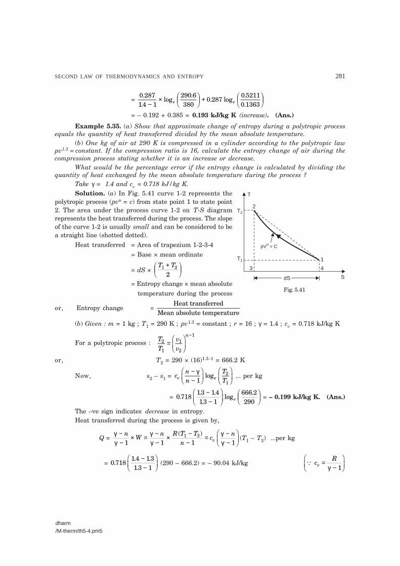
SECOND LAW OF THERMODYNAMICS AND ENTROPY 281
dharm/M-therm/th5-4.pm5
2
T
S
pV = Cn
1T1
4
T2
dS
3
= 0 28714 1
290 6380
0 2870 52110 1363
..
log.
. log..−
× ���
���
+ ���
���e e
= – 0.192 + 0.385 = 0.193 kJ/kg K (increase). (Ans.)
Example 5.35. (a) Show that approximate change of entropy during a polytropic processequals the quantity of heat transferred divided by the mean absolute temperature.
(b) One kg of air at 290 K is compressed in a cylinder according to the polytropic lawpv1.3 = constant. If the compression ratio is 16, calculate the entropy change of air during thecompression process stating whether it is an increase or decrease.
What would be the percentage error if the entropy change is calculated by dividing thequantity of heat exchanged by the mean absolute temperature during the process ?
Take γ = 1.4 and cv = 0.718 kJ/kg K.Solution. (a) In Fig. 5.41 curve 1-2 represents the
polytropic process (pvn = c) from state point 1 to state point2. The area under the process curve 1-2 on T-S diagramrepresents the heat transferred during the process. The slopeof the curve 1-2 is usually small and can be considered to bea straight line (shotted dotted).
Heat transferred = Area of trapezium 1-2-3-4= Base × mean ordinate
= dS × T T1 2
2+�
�����
= Entropy change × mean absolutetemperature during the process
or, Entropy change = Heat transferred
Mean absolute temperature
(b) Given : m = 1 kg ; T1 = 290 K ; pv1.3 = constant ; r = 16 ; γ = 1.4 ; cv = 0.718 kJ/kg K
For a polytropic process : TT
vv
n2
1
1
2
1
=�
���
��
−
or, T2 = 290 × (16)1.3–1 = 666.2 K
Now, s2 – s1 = cnn
TTv e
−−
���
���
�
���
��γ1
2
1log ... per kg
= 0 71813 1413 1
666 2290
.. ..
log.−
−���
���
���
���e = – 0.199 kJ/kg K. (Ans.)
The –ve sign indicates decrease in entropy.Heat transferred during the process is given by,
Q = γγ
γγ
γγ
−−
× = −−
× −−
= −−
���
���
nW
n R T Tn
cn
v1 1 1 11 2( )
(T1 – T2) ...per kg
= 0 7181 4 1313 1
.. ..
−−
���
��� (290 – 666.2) = – 90.04 kJ/kg � c
Rv =
−���
���γ 1
Fig. 5.41

282 ENGINEERING THERMODYNAMICS
dharm/M-therm/th5-4.pm5
Mean absolute temperature, Tmean = T T1 2
2290 666 2
2+ = + .
= 478.1 K
Approximate change of entropy = Q
Tmean= − 90 04
478 1..
= – 0.188 kJ/kg K
∴ % age error = 0 199 0 188
0 199100
. ..− × = 5.53%. (Ans.)
� The approximate value of entropy change is lower, because in the relation Q = Tav × dSactual value of heat transferred is substituted instead of approximate value (i.e., Areaunder the straight line) which is higher.
Example 5.36. 1.2 m3 of air is heated reversibly at constant pressure from 300 K to 600 K,and is then cooled reversibly at constant volume back to initial temperature. If the initial pres-sure is 1 bar, calculate :
(i) The net heat flow.
(ii) The overall change in entropy.
Represent the processes on T-S plot.
Take cp = 1.005 kJ/kg K and R = 0.287 kJ/kg K
Solution. Given : V1 = 1.2 m3 ; p1 = p2 ; T1 = 300 K ; T2 = 600 K ; p1 = 1 bar ; cp = 1.005 kJ/kg K ; R = 0.287 kJ/kg K
Fig. 5.42 shows the T-S plot of the processes.(i) The net heat flow, Q :
Mass of air, m = p VRT
1 1
1
51 10 120 287 1000 300
= × ×× ×
.( . )
= 1.394 kg
Q = Q1-2 + Q2-3
= mcp(T2 – T1) + mcv(T3 – T2)
= mcp(T2 – T1) + mcv(T1 – T2) ...(� T1 =T3)
= m(T2 – T1)(cp – cv) = m(T2 – T1) × R
= 1.394(600 – 300) × 0.287 = 120 kJ. (Ans.)
(ii) The overall change in entropy :Entropy change during constant pressure process 1-2,
S2 – S1 = mcp loge TT
2
1
�
���
��
= 1.394 × 1.005 loge 600300���
���
= 0.9711 kJ/K
Entropy change during constant volume process 2-3 ;
S3 – S2 = mcv loge
TT
m c RTTp e
3
2
1
2
�
���
��= −
�
���
��( ) log
= 1.394 × (1.005 – 0.287) loge 300600���
��� = – 0.6938 kJ/K
2
T
S
600 K
300 K
V = C
p = C
13
Fig. 5.42

SECOND LAW OF THERMODYNAMICS AND ENTROPY 283
dharm/M-therm/th5-4.pm5
∴ Overall change of entropy= (S2 – S1) + (S3 – S2)= 0.9771 + (– 0.6938) = 0.2833 kJ/K. (Ans.)
Example 5.37. A closed system contains air at a pressure 1 bar, temperature 300 K andvolume 0.018 m3. This system undergoes a thermodynamic cycle consisting of the following threeprocesses in series : (i) Constant volume heat addition till pressure becomes 5 bar, (ii) Constantpressure cooling, and (iii) Isothermal heating to initial state.
Represent the cycle on T-S and p-V plots and evaluate the change in entropy for eachprocess.
Take cp = 0.718 kJ/kg K and R = 0.287 kJ/kg K.Solution. Given : p1 = 1 bar ; T1 = 300 K ; V1 = 0.018 m3 ; p2 = 5 bar ;
cv = 0.718 kJ/kg K ; R = 0.287 kJ/kg K.
2
T
S
V = C
p = C
13
T = C
2
p
V
V = C
p = C
1
3
T = C
Fig. 5.43. T-S and p-V diagrams.
Mass of air, m = p VRT
1 1
1
51 10 0 0180 287 1000 300
= × ×× ×
( ) .( . )
= 0.0209 kg
Refer to Fig. 5.43.� Constant volume process 1-2 :
pT
pT
1
1
2
2= or T2 = T1 × = ×p
p2
1300
51
= 1500 K
∴ Change in entropy, S2 – S1 = mcv loge TT
2
1
�
���
��
= 0.0209 × 0.718 × loge 1500300���
��� = 0.0241 kJ/K. (Ans.)
� Constant pressure process 2-3 : T3 = T1 = 300 K
Now, change in entropy,
S3 – S2 = mcp loge TT
3
2
�
���
�� = m(cv + R) loge
TT
3
2
�
���
��
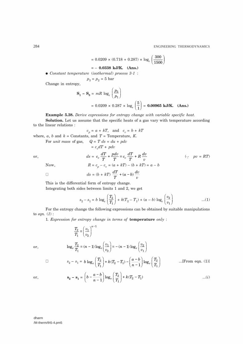
284 ENGINEERING THERMODYNAMICS
dharm/M-therm/th5-4.pm5
= 0.0209 × (0.718 + 0.287) × loge 3001500���
���
= – 0.0338 kJ/K. (Ans.)� Constant temperature (isothermal) process 3-1 :
p3 = p2 = 5 barChange in entropy,
S1 – S3 = mR loge pp
3
1
�
���
��
= 0.0209 × 0.287 × loge 51������ = 0.00965 kJ/K. (Ans.)
Example 5.38. Derive expressions for entropy change with variable specific heat.Solution. Let us assume that the specific heats of a gas vary with temperature according
to the linear relations :cp = a + kT, and cv = b + kT
where, a, b and k = Constants, and T = Temperature, K.For unit mass of gas, Q = T ds = du + pdv
= cvdT + pdv
or, ds = cdTT
pdvT
cdTT
Rdvvv v+ = + (� pv = RT)
Now, R = cp – cv = (a + kT) – (b + kT) = a – b
∴ ds = (b + kT) dTT
a bdvv
+ −( )
This is the differential form of entropy change.Integrating both sides between limits 1 and 2, we get
s2 – s1 = b loge TT
2
1
�
���
�� + k(T2 – T1) + (a – b) loge
vv2
1
�
���
��...(1)
For the entropy change the following expressions can be obtained by suitable manipulationsto eqn. (1) :
1. Expression for entropy change in terms of temperature only :
TT
vv
n2
1
1
2
1
=�
���
��
−
or, log ( ) log ( ) loge e eTT
nvv
nvv
2
1
1
2
2
11 1= −
�
���
��= − −
�
���
��
∴ s2 – s1 = bTT
k T Ta bn
TTe elog ( ) log2
12 1
2
11
�
���
��+ − − −
−���
���
�
���
��...[From eqn. (1)]
or, s2 – s1 = ba bn
TT
k T Te− −−
���
���
�
���
��+ −
12
12 1log ( ) ...(i)

SECOND LAW OF THERMODYNAMICS AND ENTROPY 285
dharm/M-therm/th5-4.pm5
2. Expression for entropy change in terms of pressure, volume and temperature.From eqn. (1), we have
s2 – s1 = bTT
k T T avv
bvve e elog ( ) log log2
12 1
2
1
2
1
�
���
��+ − +
�
���
��−
�
���
��
= avv
bTT
vv
k T Te elog log ( )2
1
2
1
1
22 1
������
+ ���
���
+ −
or, s2 – s1 = avv
bpp
k T Te elog log ( )2
1
2
12 1
�
���
��+
�
���
��+ − ...(ii)
3. Expression for entropy change in terms of pressure and temperature only.Again, from eqn. (1), we have
s2 – s1 = bTT
k T T avv
bvve e elog ( ) log log2
12 1
2
1
2
1
�
���
��+ − +
�
���
��−
�
���
��
= aTT
pp
bTT
vv
k T Te elog log ( )2
1
1
2
2
1
1
22 1×
�
���
��+ ×
�
���
��+ −
= aTT
app
bpp
k T Te e elog log log ( )2
1
2
1
2
12 1
�
���
��−
�
���
��+
�
���
��+ −
or, s2 – s1 = aTT
b app
k T Te elog ( ) log ( )2
1
2
12 1
�
���
��+ −
�
���
��+ − ...(iii)
� Derivation of the formula T b va-bekT = constant for the adiabatic expansion of gas :
We know that, ds = ( ) ( )a bdvv
b kTdTT
− + +
s2 – s1 = a v b v b T kT
a log v bTv
kT
a v bpR
kT
a vp
a bkT
e e e
e e
e e
e e
b
log log log
log
log log
log log
− + +
= + ������
+
= + ������
+
= +−
���
���
+
�
�
����
�
����
= 0 for adiabatic expansion
This gives : va pb ekT = constantpva–b
ekT = constant
Tb va–bekT = constant
The above expressions can be obtained by taking kT on right-side and taking the antilog ofthe resulting expressions.
Example 5.39. Determine the entropy change of 4 kg of a perfect gas whose temperaturevaries from 127°C to 227°C during a constant volume process. The specific heat varies linearlywith absolute temperature and is represented by the relation :
cv = (0.48 + 0.0096 T) kJ/kg K.Solution. Given : m = 4 kg ; T1 = 127 + 273 = 400 K ; T2 = 227 + 273 = 500 K ;
cv = (0.48 + 0.0096 T) kJ/kg K.

286 ENGINEERING THERMODYNAMICS
dharm/M-therm/th5-4.pm5
Entropy variation for a constant volume process is given by :
dS = mcv dTT
, or, dS = 4 × (0.48 + 0.0096T) dTT
Integrating both sides, we get,
S2 – S1 = 4 × 0.48 T
T
T
TdT dT
1
2
1
24 0 0096 + × .
= 192 2
1. loge
TT
�
���
�� + 0.0384 (T2 – T1)
= 1.92 loge 500400���
��� + 0.0384(500 – 400) = 4.268 kJ/K
i.e., S2 – S1 = 4.268 kJ. (Ans.)
Example 5.40. The specific heats of a gas vary linearly with absolute temperature accord-ing to the following relations :
cp = (0.85 + 0.00025 T) kg/kg K, andcv = (0.56 + 0.00025 T) kJ/kg KIf the entropy of the gas at 1 bar pressure and 273 K is zero, find the entropy of the gas at
25 bar and 750 K temperature.Solution. Given : cp = (0.85 + 0.00025 T) kJ/kg K ; cv = (0.56 + 0.00025 T) kJ/kg K ;
p1 = 1 bar ; T1 = 273 K ; p2 = 25 bar ; T2 = 750 K.
We know that, ds = cdTT
pT
dv cdTT
Rdvvv v+ = +
Integrating both sides, we get,
s2 – s1 = cdTT
Rvvv e+�
���
�� log 2
1
= cdTT
c cpp
TTv p v e+ − ×
�
���
�� ( ) log 1
2
2
1
= 0 56
0 00025 0 291
25750273
.. . log
TdT e+�
�����
+ ���
���
= 0 56 0 00025 0 64042
12 1. log . ( ) .e
TT
T T�
���
��+ −
�
�
���
−
= 0 56750273
. log e���
���
+ 0.00025(750 – 273) – 0.6404 = 0.0448 kJ/kg K
i.e., s2 – s1 = 0.0448 kJ/kg K. (Ans.)
Example 5.41. An insulated vessel of 0.5 m3 capacity is divided by a rigid conductingdiaphragm into two chambers A and B, each having a capacity of 0.25 m3. Chamber A containsair at 1.4 bar pressure and 290 K temperature and the corresponding parameters for air in cham-ber B are 4.2 bar and 440 K. Calculate :
(i) Final equilibrium temperature,(ii) Final pressure on each side of the diaphragm, and
(iii) Entropy change of system.For air take cv = 0.715 kJ/kg K and R = 0.287 kJ/kg K.

SECOND LAW OF THERMODYNAMICS AND ENTROPY 287
dharm/M-therm/th5-4.pm5
Solution. Given : VA = 0.25 m3 ; pAi = 1.4 bar ; TAi = 290 K ; VB = 0.25 m3 ; pBi = 4.2 bar ;TBi = 440 K ; cv = 0.715 kJ/kg K.
(i) Final equilibrium temperature, Tf :
Mass of air, mA = p VRTAi A
Ai= × ×
× ×( . ) .
( . )14 10 0 25
0 287 1000 290
5 = 0.4205 kg
mB = p VRTBi B
Bi= × ×
× ×( . ) .
( . )4 2 10 0 25
0 287 1000 440
5 = 0.8315 kg
Let Tf be the final equilibrium temperature (K). Since the diaphragm is conducting,Heat gained by air in chamber A = Heat lost by air in chamber B
mA cv (Tf – 290) = mB cv(440 – Tf)or, 0.4205 × (Tf – 290) = 0.8315(440 – Tf)or, 0.4205 Tf – 121.94 = 365.86 – 0.8315 Tf
∴ Tf = 389.6 K. (Ans.)
(ii) Final pressure on each side of the diaphragm : pAf ; pBf
pAf = 14 389 6
290. .×
= 1.88 bar. (Ans.)
pBf = 4 2 389 6
440. .×
= 3.72 bar. (Ans.)
(iii) Entropy change of the system :
Entropy change for chamber A = mA cv loge T
Tf
Ai
�
���
��
= 0.4205 × 0.715 × loge 389 6290
.���
���
= 0.0888 kJ/K
Entropy change for chamber B = mB cv loge
T
Tf
Bi
�
���
��
= 0.8315 × 0.715 × loge 389 6440
.���
���
= – 0.0723 kJ/K
∴ Net change of entropy = 0.0888 + (– 0.0723) = 0.0165 kJ/K. (Ans.)
Example 5.42. A certain gas has a specific heat at constant volume of 1.25 kJ/kg K. Whenit is expanded reversibly and adiabatically from a specific volume of 0.0624 m3/kg and a tempera-ture of 530 K to a specific volume of 0.186 m3/kg its temperature falls by 165 K. When it isexpanded into an evacuated space from the same initial condition to the same final specificvolume its temperature falls only by 25 K.
Find the change in entropy in each of the adiabatic processes.Solution. Refer Fig. 5.44.Specific heat of gas at constant volume, cv = 1.25 kJ/kg KInitial specific volume, v1 = 0.0624 m3/kgInitial temperature, T1 = 530 KFinal specific volume, v2 = 0.186 m3/kg

288 ENGINEERING THERMODYNAMICS
dharm/M-therm/th5-4.pm5
Temperature fall when expanded reversibly and adiabatically = 165 KTemperature fall when expanded into an evacuated space = 25 K
Fig. 5.44
Change in entropy :Path 1-2 : Reversible adiabatic process.Change in entropy, (s2 – s1) = 0.Path 1-3 : Adiabatic process such that v3 = 0.186 m3/kg (= v2)(States 2 and 3 lie on the same constant volume line on T-s diagram)
and T1 – T3 = 25 K.Change in entropy during this adiabatic process = s3–s1.To calculate (s3–s1) a reversible path has to be selected joining 3 and 1.This is achieved by selecting the reversible adiabatic path 1-2 and the reversible constant
volume process 2-3.s3 – s1 = (s3 – s2) + (s2 – s1)
= (s3 – s2) + 0 = (s3 – s2)
= cv loge TT
3
2 = 1.25 loge
530 25530 165
−−
��
��
= 1.25 loge 505365��
�� = 0.4058 kJ/kg K. (Ans.)
Example 5.43. A heat pump operates between two identical bodies which are at tempera-ture T1 and cools one of the bodies to a temperature T2 (T2 < T1). Prove that for this operation theminimum work required by the heat pump is given by
W cT
TT 2Tp
12
22 2 1= + −
�
���
��
where cp is the specific heat which is same for both the bodies.

SECOND LAW OF THERMODYNAMICS AND ENTROPY 289
dharm/M-therm/th5-4.pm5
Heatpump
SourceT1
SinkT2
W
Q1
Q2
Solution. The arrangement is shown in Fig. 5.45.For the minimum work absorbed by the heat pump, the heat pump must be reversed
Carnot cycle engine and the required condition is
dQT���� = 0
For infinitely small changes, we can write
c dTT c dT
Tp p1
1
2
2+ = 0
If T1′ is the final temperature of the high level reservoir, then the above equation can bewritten as
cdTT
cdTTp
T
T
pT
T1
1
2
21
1
1
2�
���
��+
�
���
��′
= 0
∴ loge TT1
1
′�
���
�� + loge
TT
2
1
������ = 0 = loge (1)
∴ loge T T
T1 2
12
′�
���
�� = loge (1)
∴ T1′ = TT12
2
Now the work given to the heat pump= Heat rejected at higher level temperature – heat picked up at lower level temperature
∴ W = c dT c dTpT
T
pT
T( ) ( )
1
1
2
1′
−
= cp [(T1′ – T1) – (T1 – T2)] = cp (T1′ + T2 – 2T1)Now substituting the value of T1′ in the above equation in terms of
T1 and T2
W cTT
T Tp= + −�
�
���
12
22 12 . Proved.
�Example 5.44. The connections of a reversible engine to three sources at 500 K, 400 K
and 300 K are shown in Fig. 5.46. It draws 1500 kJ/min of energy from the source at 800 K anddevelops 200 kJ/min of work.
(i) Determine the heat interactions with the other two sources of heat.
(ii) Evaluate the entropy change due to each heat interaction with the engine.
(iii) Total entropy change during the cycle.
Solution. Refer Fig. 5.46. Temperature of source 1 = 500 K Temperature of source 2 = 400 K Temperature of source 3 = 300 K Heat energy drawn from source 1, Q1 = 1500 kJ/min Work developed, W = 200 kJ/min.
Fig. 5.45

290 ENGINEERING THERMODYNAMICS
dharm/M-therm/th5-4.pm5
W
Q3
Q1
Source-1500 K
Source-2400 K
Source-3300 K
Q2
Heatengine
Fig. 5.46
(i) The direction of heat flow from source 1 is known as given in the problem. Assume thatthe quantities of heats Q2 and Q3 are taken from heat sources and their directions are arbitrarilychosen.
For the cyclic operation of the engine
dQT���� = 0
∴QT
QT
QT
1
1
2
2
3
3+ − = 0
and Q1 + Q2 – Q3 = W
∴ 1500500 400 300
2 3+ −Q Q = 0 ...(i)
and 1500 + Q2 – Q3 = 200 ...(ii)Solving eqns. (i) and (ii), we get
Q2 = – 1600 kJ/min and Q3 = – 300 kJ/min. The above values indicate that the direction of Q2 and Q3 are reversed. Since Q2 should be
+v and Q3 also must be +ve but both are –ve therefore, their assumed directions should be reversed.The arrangement is shown in Fig. 5.47.
Fig. 5.47

SECOND LAW OF THERMODYNAMICS AND ENTROPY 291
dharm/M-therm/th5-4.pm5
W
Q1
Q – W1
SystemT = 250 K1
HE
ReservoirT = 125 K2
(ii) Entropy change of source 1 = − QT
1
1 =
− 1500500
= – 3 kJ/K. (Ans.)
Entropy change of sink 2 = QT
2
2 = 1600
400 = 4 kJ/K. (Ans.)
Entropy change of source 3 = − QT
3
3 =
− 300300
= – 1 kJ/K. (Ans.)
(iii) Net change of the entropy = – 3 + 4 – 1 = 0As the cycle is completed, the net change in entropy must be zero because entropy is a
property.It may be observed from the new arrangement that the engine takes heat from source 1 and
source 3 and rejects to source 2, only i.e., the equipment does both a heat engine and a heat pumpfunction.
Example 5.45. The heat capacity of a system at constant volume is given by Cv = ZT2
where Z = 0.045 J/K3
A system is originally at 250 K, and a thermal reservoir at 125 K is available. Determinethe maximum amount of work that can be recovered as the system is cooled down to the tempera-ture of the reservoir.
Solution. Refer Fig. 5.48.Initial temperature of the system, T1 = 250 KTemperature of the reservoir, T2 = 125 KHeat capacity of the system at constant volume is
Cv = ZT2 = 0.045 T2
The product of mass and specific heat ( ) is called theof the substance. The capital letter ,
or is used for heat capacity
mcheat capacity C C
Cp
v
�
�
�
���
Heat removed from the system
Q C dT T dTvT
T
12
250
125
1
2045= = 0.
= 0.045 T3
250
125
3�
�
�� = 0045
3. (1253 – 2503)
= – 205.08 × 10³ J
(∆ S)system = CdTT
TdTTv
250
125
250
1252045 = 0.
= =�
�
��� 0 045 0 045
2250
125 2
250
125
. .TdTT
= 00452
. (1252 – 2502) = – 1054.7 J/K
(∆ S)reservoir = Q W
T1 −
reservoir =
205 08 10125
3. × − W J/K
Fig. 5.48

292 ENGINEERING THERMODYNAMICS
dharm/M-therm/th5-4.pm5
(∆ S)working fluid in HE = 0
∴ (∆ S)universe = (∆ S)system + (∆ S)reservoir = – 1054.7 + 20508 10125
3. × −W
Since (∆ S)universe ≥ 0
∴ – 1054.7 + 205.08 10125
3× − W ≥ 0
or – 1054.7 + 1640.64 – W125 ≥ 0 or 585.94 – W
125 ≥ 0
or 585.94 ≥ W125 or W
125 ≤ 585.94
i.e., W(max.) = 585.94 × 125 = 73.24 kJ. (Ans.)
Example 5.46. In an insulated duct air is flowing steadily. The pressure and temperaturemeasurements of the air at two stations A and B are given below :
Station Pressure Temperature A 140 kPa 60°CB 110 kPa 15°C
Establish the direction of the flow of the air in the duct.For air assume that :
cp = 1.005 kJ/kg K
h = cp T and vT =
0.287p
where p, v and T are pressure (in kPa), volume (in m3/kg) and temperature (in K) respectively.Solution. From property relation,
Tds = dh – vdp
ds = dhT – vdp
TFor two states at A and B the entropy changes of the system is given by
dsc dT
Tdpps
s p
T
T
p
p
A
B
A
B
A
B
= − 0 287.
∴ sB – sA = 1.005 loge TT
B
A – 0.287 loge
110140
= 1.005 loge 15 27360 273
++
��
�� – 0.287 loge
110140
= – 0.1459 + 0.0692 = – 0.0767 kJ/kg K(∆s)system = – 0.0767 kJ/kg K
Since the duct is insulated, (∆ s)surroundings = 0∴ (∆ s)universe = – 0.0767 kJ/kg K.This is impossible.So, the flow is from B to A. (Ans.)
Example 5.47. 3 kg of water at 80°C is mixed with 4 kg of water at 15°C in an isolatedsystem. Calculate the change of entropy due to mixing process.

SECOND LAW OF THERMODYNAMICS AND ENTROPY 293
dharm/M-therm/th5-4.pm5
Solution. Fig. 5.49 shows the isolated system before mixing. When barrier is removed, thewater from two compartments mix each other. Let tm is the final equilibrium temperature aftermixing.
Isolatedsystem
Barrier
3 kgat 80°C(Water)
4 kgat 15°C(Water)
Fig. 5.49
Applying first law of thermodynamics to the isolated system :Total energy before mixing = Total energy after mixing∴ 3cpw (80 – 0) + 4cpw (15 – 0) = 7 cpw (tm – 0)
[cpw = Specific heat of water at constant pressure]or 240cpw + 60cpw = 7cpw tmor 240 + 60 = 7 tm
∴ tm = 3007 = 42.85°C
Initial entropy of the system,
= 3cpw loge 80 273
273+�
��� + 4cpw loge
15 273273+�
���
= 0.7709cpw + 0.2139 cpw = 0.9848 cpw
Final entropy of the system
= (3 + 4) cpw loge 42.85 273
273+�
�����
= 1.0205 cpw
Net change in entropy,∆S = Final entropy – Initial entropy
= 1.0205cpw – 0.9848 cpw = 0.0357 cpw
= 0.0357 × 4.187 kJ/K [� cpw = 4.187 kJ/kg K]= 0.1495 kJ/K
Hence, net change in entropy = 0.1495 kJ/K. (Ans.)
Example 5.48. A mass ‘m’ of fluid at temperature T1 is mixed with an equal mass of the
same fluid at T2. Prove that the resultant change of entropy of the universe is 2 mc (T T )/2
T T1 2
1 2
+
and also prove that it is always positive.

294 ENGINEERING THERMODYNAMICS
dharm/M-therm/th5-4.pm5
Solution. Mean temperature of the mixture = T T1 2
2+�
����� .
Thus change in entropy is given by
∆S = mcdTT
mcdTTT
T T
T T
T
1
1 2
1 2
22
2
( )/
( )/
+
+ −
= mc loge T T
T1 2
12+�
�����
– mc loge 2 2
1 2
TT T+���
���
= mc loge T T
T1 2
12+�
�����
+ mc loge T T
T1 2
22+�
�����
= mc loge ( )T T
T T1 2
2
1 24+
= mc loge T T
T T1 2
1 2
2
2+�
�
���
= 2 mc loge T T
T T1 2
1 22+�
�
���
= 2 mc loge ( ) /T T
T T1 2
1 2
2+�
�
���
i.e., Resultant change of entropy of universe
= 2 mc loge (T T ) / 2T T
1 2
1 2
+�
�
���
...Proved
The arithmetic mean T T1 22+ is greater than geometric mean T T1 2 .
Therefore, loge ( ) /T T
T T1 2
1 2
2+ is + ve.
Thus, the entropy of the universe increases.
�Example 5.49. (a) One kg of water at 0°C is brought into contact with a heat reservoirat 90°C. When the water has reached 90°C, find :
(i) Entropy change of water ;(ii) Entropy change of the heat reservoir ;
(iii) Entropy change of the universe.
(b) If water is heated from 0°C to 90°C by first bringing it in contact with a reservoir at40°C and then with a reservoir at 90°C, what will the entropy change of the universe be ?
(c) Explain how water might be heated from 0°C to 90°C with almost no change in theentropy of the universe.
Solution. Mass of water, m = 1 kgTemperature of water, T1 = 0 + 273 = 273 KTemperature of the heat reservoir, T2 = 90 + 273 = 363 K.(a) Refer Fig. 5.50. Water is being heated through a finite temperature difference. The
entropy of water would increase and that of the reservoir would decrease so that net entropychange of the water (system) and the reservoir together would be positive definite. Water is beingheated, irreversibly, and to find the entropy change of water, we have to assume a reversible pathbetween the end states, which are at equilibrium.

SECOND LAW OF THERMODYNAMICS AND ENTROPY 295
dharm/M-therm/th5-4.pm5
System(0 + 273= 273 K)
Q
Reservoir(90 + 273 = 363 K)
(i) Entropy of water,
(∆ s)water = mcdT
TT
T
1
2
= mc loge TT
2
1
(c = Specific heat of water)
= 1 × 4.187 × loge 363273
= 1.193 kJ/kg K. (Ans.)(ii) The temperature of the reservoir remains con-
stant irrespective of the amount of the heat withdrawn.Amount of heat absorbed by the system from the
reservoir, Q = 1 × 4.187 × (363 – 273) = 376.8 kJ
∴ Entropy change of the reservoir,
(∆ s)reservoir = – QT = – 376.8
363 = – 1.038 kJ/K. (Ans.)
(–ve sign indicates decrease in entropy).(iii) Entropy change of the universe,
(∆ s)universe = (∆ s)water (or system) + (∆ s)reservoir
= 1.193 + (– 1.038) = 0.155 kJ/K. (Ans.)(b) The heating of water is being carried out in two stages, first from 0°C (273 K) to 40°C
(i.e., 313 K) by bringing in contact with a reservoir at 40°C (313 K), and then from 40°C (313 K) to90°C (363 K) by bringing in contact with a second reservoir at 90°C (363 K).
(∆ s)water = mc dTT mc dT
T273
313
313
363
+ = 1 × 4.187 log loge e313273
363313+�
���
= 4.187 (0.1367 + 0.1482) = 1.1928 kJ/K.
(∆ s)res. I = – 1 313 273
313× × −4.187 ( )
= – 0.535 kJ/K
(∆ s)res. II = – 1 363 313
363× × −4.187 ( )
= – 0.576 kJ/K
∴ (∆ s)univ. = (∆ s)water + (∆ s)res. I + (∆ s)res. II = 1.1928 + (– 0.535) + (– 0.576) = 0.0818 kJ/K.
i.e., Entropy change of universe = 0.0818 kJ/K. (Ans.)(c) The entropy change of universe would be less and less, if the water is heated in more and
more stages, by bringing the water in contact successively with more and more heat reservoirs,each succeeding reservoir being at a higher temperature than the preceding one. When water isheated in infinite steps, by bringing in contact with an infinite number of reservoirs in succession,so that at any instant the temperature difference between the water and the reservoir in contact isinfinitesimally small, then the entropy change of the universe would be zero and the water wouldbe reversibly heated.
Example 5.50. 1 kg of ice at – 5°C is exposed to the atmosphere which is at 25°C. The icemelts and comes into thermal equilibrium.
(i) Determine the entropy increase of the universe.
Fig. 5.50

296 ENGINEERING THERMODYNAMICS
dharm/M-therm/th5-4.pm5
(ii) What is the minimum amount of work necessary to convert the water back into ice at– 5°C ?
Take : cp of ice = 2.093 kJ/kg°CLatent heat of fusion of ice = 333.33 kJ/kg.
Solution. Mass of ice, m = 1 kgTemperature of ice = – 5°C (= – 5 + 273 = 268 K)Temperature of atmosphere = 25°C (= 25 + 273 = 298 K)Heat absorbed by ice from the atmosphere (Fig. 5.51)
= Heat absorbed in solid phase + latent heat+ heat absorbed in liquid phase
= 1 × 2.093 × [0 – (– 5)] + 1 × 333.33 + 1 × 4.187 × (25 – 0) = 10.46 + 333.33 + 104.67 = 448.46 kJ.(i) Entropy increase of the universe, (∆ s)universe :
Entropy change of the atmosphere,
(∆ s)atm. = – QT = –
448.46298
= – 1.5049 kJ/K
Entropy change of system (ice) as it gets heated from – 5°Cto 0°C,
(∆ sI)system = mc dTTp
268
273
= 1 × 2.093 loge 273268 = 0.0386 kJ/K
Entropy change of the system as ice melts at 0°C to become water at 0°C.
(∆ sII)system = 333.33
273 = 1.2209 kJ/K
Entropy change of water as it gets heated from 0°C to 25°C
(∆ sIII)system = mc dTTp
273
298
= 1 × 4.187 loge 298273��
�� = 0.3668 kJ/K
Total entropy change of ice as it melts into water(∆ s)total = ∆ sI + ∆ sII + ∆ sIII
= 0.0386 + 1.2209 + 0.3668 = 1.6263 kJ/KThen temperature-entropy diagram for the system as ice at – 5°C converts to water at 25°C
is shown in Fig. 5.52.∴ Entropy increase of the universe,
(∆ s)univ. = (∆s)system + (∆s)atm.= 1.6263 + (– 1.5049) = 0.1214 kJ/K. (Ans.)
(ii) Minimum amount of work necessary to convert the water back into ice at– 5°C, Wmin. :
To convert 1 kg of water at 25°C to ice at – 5°C, 448.46 kJ of heat have to be removed fromit, and the system has to be brought from state 4 to state 1 (Fig. 5.52). A refrigerator cycle, asshown in Fig. 5.53, is assumed to accomplish this. The entropy change of the system would be thesame, i.e., s4 – s1, with the only difference that its sign will be negative, because heat is removedfrom the system (Fig. 5.52).
(∆s)system = s1 – s4 (negative)
Fig. 5.51

SECOND LAW OF THERMODYNAMICS AND ENTROPY 297
dharm/M-therm/th5-4.pm5
Fig. 5.52
The entropy change of the working fluid in the refrigerator would be zero, since it is operat-ing in a cycle, i.e.,
(∆s)refrigerator = 0.The entropy change of the atmosphere (positive),
(∆s)atm. = Q WT+
∴ Entropy change of the universe(∆s)univ. = (∆s)system + (∆s)refrigerator + (∆s)atm.
= (s1 – s4) + 0 + Q WT+ = (s1 – s4) + Q W
T+
By the principle of increase of entropy (∆s)univ. or isolated system ≥ 0
∴ ( )s s Q WT1 4− + +�
��� ≥ 0
∴ Q WT+ ≥ (s4 – s1)
W ≥ T (s4 – s1) – Q
W(min) = T (s4 – s1) – Q
Here Q = 448.46 kJT = 298 K

298 ENGINEERING THERMODYNAMICS
dharm/M-therm/th5-4.pm5
W
System
Atmosphere at298 K
HE
1 kg water at25°C to ice at
– 5°C
Q = 448.46 kJ
Q + W
Fig. 5.53
s4 – s1 = 1.6263 kJ/K∴ W(min) = 298 × 1.6263 – 448.46 = 36.17 kJ. (Ans.)
����������
1. Clausius statement :“It is impossible for a self-acting machine working in a cyclic process, unaided by any external agency, toconvey heat from a body at a lower temperature to a body at a higher temperature.”Kelvin-Planck statement :“It is impossible to construct an engine, which while operating in a cycle produces no other effect except toextract heat from a single reservoir and do equivalent amount of work”.Although above statements of second law of thermodynamic appear to be different, they are really equiva-lent in the sense that violation of either statement implies violation of other.
2. Perpetual motion machine of second kind (PMM2) is that imaginary machine which would continu-ously absorb heat from a single thermal reservoir and convert this heat completely into work. The effi-ciency of such a machine would be 100%.
3. Clausius inequality is given by,
Cycle∑ �
�����
δQT ≤ 0
“When a system performs a reversible cycle, then
Cycle∑ ������
δQT = 0,

SECOND LAW OF THERMODYNAMICS AND ENTROPY 299
dharm/M-therm/th5-4.pm5
but when the cycle is not reversible
Cycle∑ ������
δQT < 0.’’
4. ‘Entropy’ is a function of a quantity of heat which shows the possibility of conversion of that heat intowork. The increase in entropy is small when heat is added at a high temperature and is greater when heataddition is made at lower temperature. Thus for maximum entropy, there is a minimum availability forconversion into work and for minimum entropy there is maximum availability for conversion into work.
5. Entropy changes for a closed system (per kg) :(i) General case :
(a) cv loge TT
21
+ R loge vv21
(in terms of T and v)
(b) cv loge pp21
+ cp loge vv21
(in terms of p and v)
(c) cp loge TT
21
– R loge pp
2
1 (in terms of T and p)
(ii) Constant volume : cv loge TT
21
(iii) Constant pressure : cp loge TT
21
(iv) Isothermal : R loge vv21
(v) Adiabatic : zero
(vi) Polytropic : cv nn
−−
���
���
γ1
loge TT
21
.
6. Entropy change for an open system
dS ≥ dQT0
+ Σsi . dmi – Σs0 . dm0
where, T0 = Temperature of the surroundings.Subscripts i and 0 refer to inlet and outlet conditions.
OBJECTIVE TYPE QUESTIONS
Choose the Correct Answer :1. Second law of thermodynamics defines
(a) heat (b) work (c) enthalpy(d) entropy (e) internal energy.
2. For a reversible adiabatic process, the change in entropy is(a) zero (b) minimum (c) maximum(d) infinite (e) unity.
3. For any reversible process, the change in entropy of the system and surroundings is
(a) zero (b) unity (c) negative
(d) positive (e) infinite.4. For any irreversible process the net entropy change is
(a) zero (b) positive (c) negative
(d) infinite (e) unity.

300 ENGINEERING THERMODYNAMICS
dharm/M-therm/th5-4.pm5
5. The processes of a Carnot cycle are(a) two adiabatic and two constant volume(b) one constant volume and one constant pressure and two isentropics(c) two adiabatics and two isothermals (d) two constant volumes and two isothermals(e) two isothermals and two isentropics.
6. Isentropic flow is(a) irreversible adiabatic flow (b) ideal fluid flow (c) perfect gas flow(d) frictionless reversible flow (e) reversible adiabatic flow.
7. In a Carnot engine, when the working substance gives heat to the sink(a) the temperature of the sink increases(b) the temperature of the sink remains the same(c) the temperature of the source decreases(d) the temperatures of both the sink and the source decrease(e) changes depend on the operating conditions.
8. If the temperature of the source is increased, the efficiency of the Carnot engine(a) decreases (b) increases(c) does not change (d) will be equal to the efficiency of a practical engine(e) depends on other factors.
9. The efficiency of an ideal Carnot engine depends on(a) working substance (b) on the temperature of the source only(c) on the temperature of the sink only(d) on the temperatures of both the source and the sink(e) on the construction of engine.
10. The efficiency of a Carnot engine using an ideal gas as the working substance is
(a)T T
T1 2
1
− (b)
T
T T1
1 2− (c)T T
T T1 2
1 2−
(d)T T
T T1 2
1 2
−(e)
T T T
T T T2 1 2
1 1 2
( )
( )
−+ .
11. In a reversible cycle, the entropy of the system
(a) increases (b) decreases
(c) does not change (d) first increases and then decreases
(e) depends on the properties of working substance.12. A frictionless heat engine can be 100% efficient only if its exhaust temperature is
(a) equal to its input temperature (b) less than its input temperature
(c) 0°C (d) 0°K (e) – 100°C.13. Kelvin-Planck’s law deals with
(a) conservation of energy (b) conservation of heat (c) conservation of mass(d) conversion of heat into work (e) conversion of work into heat.
14. Which of the following statements is correct according to Clausius statement of second law ofthermodynamics ?(a) It is impossible to transfer heat from a body at a lower temperature to a body at a higher temperature(b) It is impossible to transfer heat from a body at a lower temperature to a body at a higher temperature,
without the aid of an external source.(c) It is possible to transfer heat from a body at a lower temperature to a body at a higher temperature by
using refrigeration cycle(d) None of the above.

SECOND LAW OF THERMODYNAMICS AND ENTROPY 301
dharm/M-therm/th5-4.pm5
15. According to Kelvin-Planck’s statement of second law of thermodynamics
(a) It is impossible to construct an engine working on a cyclic process, whose sole purpose is to convert heatenergy into work
(b) It is possible to construct an engine working on a cyclic process, whose sole purpose is to convert theheat energy into work
(c) It is impossible to construct a device which while working in a cyclic process produces no effect otherthan the transfer of heat from a colder body to a hotter body
(d) When two dissimilar metals are heated at one end and cooled at the other, the e.m.f. developed isproportional to the difference of their temperatures at the two end.
(e) None of the above.
16. The property of a working substance which increases or decreases as the heat is supplied or removed in areversible manner is known as
(a) enthalpy (b) internal energy
(c) entropy (d) external energy.
17. The entropy may be expressed as a function of
(a) pressure and temperature (b) temperature and volume
(c) heat and work (d) all of the above
(e) none of the above.
18. The change of entropy, when heat is absorbed by the gas is
(a) positive (b) negative (c) positive or negative.
19. Which of the following statements is correct ?
(a) The increase in entropy is obtained from a given quantity of heat at a low temperature
(b) The change in entropy may be regarded as a measure of the rate of the availability of heat fortransformation into work
(c) The entropy represents the maximum amount of work obtainable per degree drop in temperature
(d) All of the above.
20. The condition for the reversibility of a cycle is
(a) the pressure and temperature of working substance must not differ, appreciably from those of thesurroundings at any stage in the process
(b) all the processes taking place in the cycle of operation, must be extremely slow
(c) the working parts of the engine must be friction free
(d) there should be no loss of energy during the cycle of operation
(e) all of the above.
21. In an irreversible process there is a
(a) loss of heat (b) no loss of work
(c) gain of heat (d) no gain of heat.
22. The main cause for the irreversibility is
(a) mechanical and fluid friction (b) unrestricted expansion
(c) heat transfer with a finite temperature difference
(d) all of the above.
23. The efficiency of the Carnot cycle may be increased by
(a) increasing the highest temperature (b) decreasing the highest temperature
(c) increasing the lowest temperature (d) decreasing the lowest temperature
(e) keeping the lowest temperature constant.

302 ENGINEERING THERMODYNAMICS
dharm/M-therm/th5-4.pm5
24. Which of the following is the correct statement ?
(a) All the reversible engines have the same efficiency
(b) All the reversible and irreversible engines have the same efficiency
(c) Irreversible engines have maximum efficiency
(d) All engines are designed as reversible in order to obtain maximum efficiency.
Answers1. (d) 2. (a) 3. (a) 4. (b) 5. (e) 6. (e) 7. (b)8. (b) 9. (d) 10. (a) 11. (c) 12. (d) 13. (d) 14. (b)
15. (e) 16. (c) 17. (a) 18. (a) 19. (d) 20. (e) 21. (a)22. (d) 23. (d) 24. (a).
THEORETICAL QUESTIONS
1. State the limitations of first law of thermodynamics.
2. What is the difference between a heat engine and a reversed heat engine ?
3. Enumerate the conditions which must be fulfilled by a reversible process. Give some examples of idealreversible processes.
4. What is an irreversible process ? Give some examples of irreversible processes.
5. Give the following statements of second law of thermodynamics.
(i) Clausius statement
(ii) Kelvin-Planck statement.
6. Define heat engine, refrigerator and heat pump.
7. What is the perpetual motion machine of the second kind ?
8. What do you mean by ‘Thermodynamic temperature’ ?
9. What do you mean by ‘Clausius inequality’ ?
10. Describe the working of a Carnot cycle.
11. Derive an expression for the efficiency of the reversible heat engine.
12. What do you mean by the term ‘Entropy’ ?
13. What are the characteristics of entropy ?
14. Prove that entropy is a property of a system.
15. Derive an expression for the change in entropy of the universe.
16. What is a temperature-entropy diagram ?
17. Derive expressions for entropy changes for a closed system in the following cases :
(i) General case for change of entropy of a gas
(ii) Heating a gas at constant volume
(iii) Heating a gas at constant pressure
(iv) Polytropic process.
18. Give an expression for entropy changes for an open system.
UNSOLVED EXAMPLES
Heat Engines and Reversible Heat Engines1. A cyclic heat engine operates between a source temperature of 800°C and a sink temperature of 30°C.
What is the least rate of heat rejection per kW net output of the engine ? [Ans. 0.392 kW]

SECOND LAW OF THERMODYNAMICS AND ENTROPY 303
dharm/M-therm/th5-4.pm5
2. A domestic food freezer maintains a temperature of – 15°C. The ambient air temperature is 30°C. If heatleaks into the freezer at the continuous rate of 1.75 kJ/s what is the least power necessary to pump thisheat out continuously. [Ans. 0.31 kW]
3. A reversible heat engine operates between two reservoirs at temperatures of 600°C and 40°C. The enginedrives a reversible refrigerator which operates between reservoirs at temperatures of 40°C and – 20°C.The heat transfer to the heat engine is 2000 kJ and the net work output for the combined engine refrigera-tor is 360 kJ. (i) Calculate the heat transfer to the refrigerant and the net heat transfer to the reservoir at40°C. (ii) Reconsider (i) given that the efficiency of the heat engine and the C.O.P. of the refrigerator areeach 40 per cent of their maximum possible values.
[Ans. Heat rejection to 40°C reservoir (i) 5539 kJ ; (ii) 1899.6 kJ]
4. A heat engine is supplied heat at the rate of 1700 kJ/min and gives an output of 9 kW. Determine thethermal efficiency and the rate of heat rejection. [Ans. 31.76% ; 9.333 kJ/s]
5. What is the highest possible theoretical efficiency of a heat engine operating with a hot reservoir of furnacegases at 2000°C when the cooling water available is at 10°C ? [Ans. 87.54%]
6. A Carnot cycle operates between source and sink temperatures of 260°C and – 17.8°C. If the systemreceives 100 kJ from the source, find (i) efficiency of the system, (ii) the net work transfer, (iii) heatrejected to the sink. [Ans. 52.2% ; 52.2 kJ ; 47.8 kJ]
7. Source A can supply energy at a rate of 11000 kJ/min at 320°C. A second source B can supply energy at arate of 110000 kJ/min at 68°C. Which source A or B, would you choose to supply energy to an idealreversible engine that is to produce large amount of power if the temperature of the surroundingsis 40°C ? [Ans. Source B]
8. A fish freezing plant requires 50 tons of refrigeration. The freezing temperature is – 40°C while theambient temperature is 35°C. If the performance of the plant is 15% of the theoretical reversed Carnotcycle working within the same temperature limits, calculate the power required. [Ans. 375 kW]
Take 1 ton = 210 kJ/ min.
Clausius Inequality9. A heat engine is supplied with 278 kJ/s of heat at a constant fixed temperature of 283°C and the heat
rejection takes place at 5°C. The following results were reported : (i) 208 kJ/s are rejected, (ii) 139 kJ/s arerejected, (ii) 70 kJ/s are rejected.
Classify which of the results report a reversible cycle or irreversible cycle or impossible results.
[Ans. (i) Irreversible (ii) Reversible (iii) Impossible]
Entropy
10. Air at 15°C and 1.05 bar occupies 0.02 m3. The air is heated at constant volume until the pressure is 4.2 bar,and then cooled at constant pressure back to the original temperature. Calculate the net heat flow to orfrom the air and the net entropy change.
Sketch the process on a T-s diagram.
[Ans. Heat rejected = 6.3 kJ, decrease in entropy of air = 0.0101 kJ/K]
11. 0.03 m3 of nitrogen contained in a cylinder behind a piston is initially at 1.05 bar and 15°C. The gas iscompressed isothermally and reversibly until the pressure is 4.2 bar. Calculate the change of entropy, theheat flow, and the work done, and sketch the process on a p-v and T-s diagrams. Assume nitrogen to act asa perfect gas. Molecular weight of nitrogen = 28.
[Ans. 0.01516 kJ/K (decrease) ; 4.37 kJ (heat rejected) ; 4.37 kJ]
12. Calculate the change of entropy of 1 kg of air expanding polytropically in a cylinder behind a piston from6.3 bar and 550°C to 1.05 bar. The index of expansion is 1.3. [Ans. 0.1 kJ/kg K (increase)]
13. 0.05 kg of carbon dioxide (molecular weight = 44) is compressed from 1 bar, 15°C, until the pressure is8.3 bar, and the volume is then 0.004 m3. Calculate the change of entropy. Take cp for carbon dioxide as0.88 kJ/kg K, and assume carbon dioxide to be a perfect gas. [Ans. 0.0113 kJ/K (decrease)]

304 ENGINEERING THERMODYNAMICS
dharm/M-therm/th5-4.pm5
14. In an air turbine the air expands from 6.8 bar and 430°C to 1.013 bar and 150°C. The heat loss from theturbine can be assumed to be negligible. Show that the process is irreversible, and calculate the change ofentropy per kg of air. [Ans. 0.0355 kJ/kg K (increase)]
15. (i) One kg of water at 273 K is brought into contact with a heat reservoir at 373 K. When the water hasreached 373 K, find the entropy change of the water of the heat reservoir, and of the universe.
(ii) If water is heated from 273 K to 373 K by first bringing it in contact with a reservoir at 323 K and thenwith reservoir at 373 K, what will the entropy change of the universe be ?
[Ans. (i) 0.183 kJ/K ; (ii) 0.098 kJ/K]
16. One kg of ice at – 5°C is exposed to the atmosphere which is at 20°C. The ice melts and comes into thermalequilibrium with the atmosphere.
(i) Determine the entropy increase of the universe.
(ii) What is the minimum amount of work necessary to convert the water back into ice at – 5°C ? cp of iceis 2.093 kJ/kg °C and the latent heat of fusion of ice is 333.3 kJ/kg.
[Ans. (i) 0.0949 kJ/K (increase) (ii) 28.5 kJ]
17. A system has a heat capacity at constant volume Cv = AT2, where A = 0.042 J/K3. The system is originallyat 200 K and a thermal reservoir at 100 K is available. What is the maximum amount of work that can berecovered as the system is cooled down to the temperature of the reservoir ? [Ans. 35 kJ]
18. A fluid undergoes a reversible adiabatic compression from 0.5 MPa, 0.2 m3 to 0.05 m3 according to the law,pv1.3 = constant. Determine the change in enthalpy, internal energy and entropy, and the heat transfer andwork transfer during the process. [Ans. 223.3 kJ ; 171.77 kJ, ; zero ; zero ; – 171.77 kJ]
19. A rigid cylinder containing 0.006 m3 of nitrogen (molecular weight 28) at 1.04 bar, 15°C, is heated reversiblyuntil the temperature is 90°C. Calculate the change of entropy and the heat supplied. Sketch the processon T-s diagram. Take the isentropic index, γ, for nitrogen as 1.4, and assume that nitrogen is a perfect gas.
[Ans. 0.00125 kJ/K ; 0.407 kJ]
20. 1 m3 of air is heated reversibly at constant pressure from 15°C to 300°C, and is then cooled reversibly atconstant volume back to the initial temperature. The initial pressure is 1.03 bar. Calculate the net heat flowand overall change of entropy, and sketch the process on a T-s diagram. [Ans. 101.5 kJ ; 0.246 kJ/K]
21. 1 kg of air is allowed to expand reversibly in a cylinder behind a piston in such a way that the temperatureremains constant at 260°C while the volume is doubled. The piston is then moved in, and heat is rejected bythe air reversibly at constant pressure until the volume is the same as it was initially. Calculate the net heatflow and the overall change of entropy. Sketch the processes on a T-s diagram.
[Ans. – 161.9 kJ/kg ; – 0.497 kJ/kg K]
22. 1 kg of air at 1.013 bar, 17°C, is compressed according to a law pv1.3 = constant, until the pressure is 5 bar.Calculate the change of entropy and sketch the process on a T-s diagram, indicating the area, whichrepresents the heat flow. [Ans. – 0.0885 kJ/kg K]
23. 0.06 m3 of ethane (molecular weight 30), at 6.9 bar and 60°C, is allowed to expand isentropically in a cylinderbehind a piston to a pressure of 1.05 bar and a temperature of 107°C. Calculate γ, R, cp, cv for ethane, andcalculate the work done during the expansion. Assume ethane to be a perfect gas.
The same mass of ethane at 1.05 bar, 107°C, is compressed to 6.9 bar according to a law pv1.4 = constant.Calculate the final temperature of the ethane and the heat flow to or from the cylinder walls during thecompression. Calculate also the change of entropy during the compression, and sketch both processes onp-v and T-s diagrams.
[Ans. 1.219 ; 0.277 kJ/kg K ; 1.542 kJ/kg K ; 1.265 kJ/kg K ; 54.2 kJ ; 378°C ; 43.4 kJ ; 0.0867 kJ/K]
24. In a reversible process the rate of heat transfer to the system per unit temperature rise is given
bydQdT = 0.5 kJ/°C. Find the change in entropy of the system if its temperature rises from 500 K to 800 K.
[Ans. 0.235 kJ/kg°C]

SECOND LAW OF THERMODYNAMICS AND ENTROPY 305
dharm/M-therm/th5-4.pm5
25. In a reversible cycle 100 kJ of heat is received at 500 K ; then an adiabatic expansion occurs to 400 K, atwhich temperature 50 kJ of heat is received, then a further adiabatic expansion to 300 K at whichtemperature 100 kJ of heat is rejected :
(i) Find the change in entropy which occurs as the system is restored to its initial state in the remainderof the cycle.
(ii) If during the remainder of the cycle heat is transferred only at 400 K, how much heat is transferred andin what direction ? [Ans. 0.008 kJ/K ; + 3.2 kJ]
26. 1 kg of air is compressed according to the law pv1.25 = constant from 1.03 bar and 15°C to 16.45 bar.Calculate the change in entropy. [Ans. 0.255 kJ/kg K]
27. A quantity of gas (mean molecular weight 36.2) is compressed according to the law pvn = constant, theinitial pressure and volume being 1.03 bar and 0.98 m3 respectively. The temperature at the start ofcompression is 17°C and at the end it is 115°C. The amount of heat rejected during compression is 3.78 kJ,cp = 0.92. Calculate :
(i) Value of n, (ii) Final pressure, (iii) Change in entropy.
[Ans. (i) 1.33 ; (ii) 1.107 bar ; (iii) 0.228 kJ/kg K]