sebastian torres nexrad range-velocity ambiguity mitigation spring 2004 – technical interchange...
TRANSCRIPT

Sebastian Torres
NEXRAD Range-Velocity Ambiguity Mitigation
Spring 2004 – Technical Interchange Meeting

Part One
Update on Previous Work

148 km184 km
KTLXVCP 11 – Batch Mode
KOUNStaggered PRT (184 km/276 km)EL = 2.5 deg
04/06/03 4:42 GMT
va = 25.4 m s-1 va = 45.2 m s-1
The Staggered PRT AlgorithmImages with artifacts

va = 25.4 m s-1 va = 45.2 m s-1
KTLXVCP 11 – Batch Mode
KOUNStaggered PRT (184 km/276 km)EL = 2.5 deg
04/06/03 4:42 GMT
The Staggered PRT AlgorithmCorrect Images

Time-Domain Filter5-Pole Elliptic Filter
Frequency-Domain FilterFixed Notch FilterEL = 1.5 deg
02/14/03 1:06 GMT
The SZ-2 AlgorithmGround Clutter Filter Effects

Part Two
The GMAP Ground Clutter Filter

How does GMAP work?
• Inputs– Power spectrum
• from time-series data– Apply window– Compute DFT– Compute magnitude squared
– Noise level (optional)– Ground clutter spectrum width
• Outputs– Filtered power spectrum– Removed power

10 20 30 40 50 60
-20
-10
0
10
20
k
Sso
rte
dRank-order power spectrum
10 20 30 40 50 60
-20
-10
0
10
20
k
S
Original power spectrum
How does GMAP work?
10 20 30 40 50 60
-20
-10
0
10
20
k
Sso
rte
dRank-order power spectrum
10 20 30 40 50 60
-20
-10
0
10
20
k
S
Original power spectrum
White noise
10 20 30 40 50 60
-20
-10
0
10
20
k
Sso
rte
dRank-order power spectrum
10 20 30 40 50 60
-20
-10
0
10
20
k
S
Original power spectrum
Signal Noise
White noise
• Noise power computation using rank order technique– Sort power spectrum– Compare with theoretical
curve for white noise– Find component at which
power spectrum departsfrom white noise
– Identify noise components
– Compute noise power

How does GMAP work?
• Clutter filtering– Generate clutter model
based on c, Ts, M, and window
– Determine notch width (gap) from clutter model and noise level
– Notch clutter components

How does GMAP work?
• Spectrum reconstruction– Compute v and v from signal components
– Fill gap with signal model • Re-compute v and v
– Repeat until v and v converge
• Compute removed power– Subtract reconstructed power from original
power in the gap

GMAP Analysis Tool
• MATLAB port from RVP8 RDA 8.04 (4 Nov 2003)– No significant changes to GMAP in
subsequent releases • Current release: RVP8 RDA 8.05.2 (29 Mar 2004)
– Ported function fSpecFilterGMAP() and all supporting functions
• Tool is useful for qualitative analysis

GMAP Analysis Tool

GMAP Performance
• GMAP noise estimation– Inadequate for small number of samples
• GMAP interpolation– Restores weather signal power in the gap
• GMAP in the absence of clutter– Some components are filtered nevertheless– Spectrum can become distorted

Estimating Clutter Power from GMAP
• Simulation:– Input: Signal + Clutter
• Signal velocity is random in (-va, va)• Signal spectrum width is 1, 2, 4, and 8 m/s• CSR is varied from -30 to 50 dB• CNR > 20 dB for all cases
– Process: GMAP – Output: Removed power PREM
• Goal: Establish suitability of PREM as an estimate of clutter power

-30 -20 -10 0 10 20 30 40 50-5
0
5
10
Bia
s(P
RE
M)
(dB
)
Bias
-30 -20 -10 0 10 20 30 40 504
6
8
10
12
SD
(PR
EM
) (d
B)
Standard Deviation
-30 -20 -10 0 10 20 30 40 500
10
20
30
40
50
60
CSR (dB)
% o
f ca
ses
PREM
= 0
v = 1 m/s
v = 2 m/s
v = 4 m/s
v = 8 m/s
M = 64 10000 realizationsBlackman window
Cases with PREM
= 0 are ignored
Cases with PREM
= 0 are ignored
Estimating Clutter Power from GMAP
• Removed power from GMAP is unreliable as an estimate of clutter power, especially for low CSR
CSR(dB)
-30 -20 -10 0 10 20 30 40 50-5
0
5
10
Bia
s(P
RE
M)
(dB
)
Bias
-30 -20 -10 0 10 20 30 40 504
6
8
10
12
SD
(PR
EM
) (d
B)
Standard Deviation
-30 -20 -10 0 10 20 30 40 500
10
20
30
40
50
60
CSR (dB)%
of c
ase
s
PREM
= 0
v = 1 m/s
v = 2 m/s
v = 4 m/s
v = 8 m/s
M = 64 10000 realizationsBlackman window
Cases with PREM
= 0 are ignored
Cases with PREM
= 0 are ignored
PREM = 0 if clutter filtering “adds” power

Suitability of GMAP
• Algorithm is not available in the literature– Details are proprietary– Uses several “empirical constants”
• GMAP works better for large M– Modifications made by SIGMET to handle small M
• Ice et al. (2004) reported compliance with NEXRAD requirements using “black-box” analysis– Recommended using Blackman window and providing
noise level to GMAP
• Good candidate for SZ: no phase distortion– Minor changes are required (stay tuned!)

Part Three
GMAP and Phase Coding

GMAP and Phase Coding
• GMAP designed for uniform sampling, non-phase coded signals
• Issues:– Window effect– Noise estimation– Spectral reconstruction– Filtered time series

Window Effect
• Window choice– Sachidanda et al. (NSSL Report
2, 1998) recommend Von Hann window to minimize errors
– Ice et al. (ORDA Report, 2004) recommend Blackman window to achieve larger clutter suppression
• Blackman is more aggressive than Von Hann– Should expect larger errors of
estimates

Window Effect
• Simulation:– Input: Signal in the 1st trip + Signal in the 2nd trip
• 1st Trip Signal: – Velocity is random in (-va, va)
– Spectrum width varies from 0.5 to 8 m/s
• 2nd Trip Signal: – Velocity is random in (-va, va)
– Spectrum width is 1, 2, 4, and 8 m/s
• S1/S2 varies from 0 to 70 dB
– Process: SZ-2 with GMAP• Case 1: Blackman window• Case 2: Von Hann window
– Output: Statistics of v1 and v2 estimates

Window Effect
Blackman Window Von Hann Window

Noise Estimation
• Issue: Use GMAP noise estimation or provide noise to it?
• Out-of-trip echo looks like white noise– GMAP noise estimation fails– GMAP notch width based on over-estimated noise
level is narrower than required

Noise Estimation
• Simulation:– Input: Signal in the 1st trip + Signal in the 2nd trip
+ Clutter in the 1st trip• 1st Trip Signal:
– Velocity is random in (-va, va)– Spectrum width varies from 0.5 to 8 m/s
• 2nd Trip Signal: – Velocity is random in (-va, va)– Spectrum width is 1, 2, 4, and 8 m/s
• S1/S2 varies from 0 to 70 dB• C/S1 varies from -30 to 50 dB
– Process: SZ-2 with GMAP• Case 1: GMAP with noise estimation• Case 2: GMAP with provided noise
– Output: Statistics of v2 estimates

Noise Estimation
GMAP with noise estimation GMAP with provided noise

Spectrum Reconstruction
• Issue: Use GMAP interpolation or apply notch filter?
• Interpolation helps reducing biases (in strong signal moments) due to clutter filtering
• Interpolation assumes coherent weather signal is present after clutter filtering
• Two cases to consider:– Clutter with the strong signal– Clutter with the weak signal

Spectrum Reconstruction
• Clutter with the strong signal
v

Spectrum Reconstruction
• Simulation:– Input: Signal in the 1st trip + Signal in the 2nd trip
+ Clutter in the 1st trip• 1st Trip Signal:
– Velocity is random in (-va, va)– Spectrum width varies from 0.5 to 8 m/s
• 2nd Trip Signal: – Velocity is random in (-va, va)– Spectrum width is 1, 2, 4, and 8 m/s
• S1/S2 varies from 0 to 70 dB• C/S1 varies from -30 to 50 dB
– Process: SZ-2 with GMAP• Case 1: GMAP with interpolation• Case 2: GMAP without interpolation
– Output: Statistics of v1 estimates

Spectrum Reconstruction
GMAP with interpolation GMAP without interpolation

Spectrum Reconstruction
• Clutter with the weak signal
v

Spectrum Reconstruction
• Simulation:– Input: Signal in the 1st trip + Signal in the 2nd trip
+ Clutter in the 2nd trip• 1st Trip Signal:
– Velocity is random in (-va, va)– Spectrum width varies from 0.5 to 8 m/s
• 2nd Trip Signal: – Velocity is random in (-va, va)– Spectrum width is 1, 2, 4, and 8 m/s
• S1/S2 varies from 0 to 70 dB• C/S1 varies from -30 to 50 dB
– Process: SZ-2 with GMAP• Case 1: GMAP with interpolation• Case 2: GMAP without interpolation
– Output: Statistics of v1 estimates

Spectrum Reconstruction
GMAP with interpolation GMAP without interpolation

Filtered Time Series
• GMAP returns power spectrum
• Phases must be saved to reconstruct full spectrum and return to time domain
• Issue: What are the phases of the reconstructed components?– Original phases– Zero phases– Something else?
Filtered Time Series
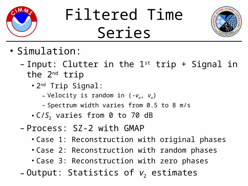
• Simulation:– Input: Clutter in the 1st trip + Signal in the 2nd trip
• 2nd Trip Signal: – Velocity is random in (-va, va)
– Spectrum width varies from 0.5 to 8 m/s
• C/S2 varies from 0 to 70 dB
– Process: SZ-2 with GMAP• Case 1: Reconstruction with original phases• Case 2: Reconstruction with random phases• Case 3: Reconstruction with zero phases
– Output: Statistics of v2 estimates

Filtered Time Series
1 2 3 4 5 6 7 8-30
-20
-10
0
10
20
30
40
50
2 (m/s)
C/S
2 (dB
)
sd(v2) scale
0 m/s
1 m/s
2 m/s
3 m/s
4 m/s
5 m/s
1 2 3 4 5 6 7 8-30
-20
-10
0
10
20
30
40
50
2 (m/s)
C/S
2 (dB
)
bias(v2)
SZ-2 Algorithm - Clutter in 1st trip, Random phasesscale
-2 m/s
-1 m/s
0 m/s
1 m/s
2 m/s
1 2 3 4 5 6 7 8-30
-20
-10
0
10
20
30
40
50
2 (m/s)
C/S
2 (dB
)
sd(v2) scale
0 m/s
1 m/s
2 m/s
3 m/s
4 m/s
5 m/s
1 2 3 4 5 6 7 8-30
-20
-10
0
10
20
30
40
50
2 (m/s)
C/S
2 (dB
)
bias(v2)
SZ-2 Algorithm - Clutter in 1st trip, Zero phasesscale
-2 m/s
-1 m/s
0 m/s
1 m/s
2 m/s
1 2 3 4 5 6 7 8-30
-20
-10
0
10
20
30
40
50
2 (m/s)
C/S
2 (dB
)
sd(v2) scale
0 m/s
1 m/s
2 m/s
3 m/s
4 m/s
5 m/s
1 2 3 4 5 6 7 8-30
-20
-10
0
10
20
30
40
50
2 (m/s)
C/S
2 (dB
)
bias(v2)
SZ-2 Algorithm - Clutter in 1st trip, Original phasesscale
-2 m/s
-1 m/s
0 m/s
1 m/s
2 m/s
Original Phases Random Phases Zero Phases
Weather is in the 2nd trip and Clutter is in the 1st trip

GMAP and Phase CodingSummary
• Use Blackman window for required suppression at the expense of loss of accuracy
• Provide noise level to GMAP• Reconstruct filtered spectrum using zero
phases in the “gap”• Use GMAP interpolation if clutter is with
strong signal• Don’t use GMAP interpolation if clutter is
with weak signal

GMAP vs. Elliptic GCF
VelocitySZ-2 with medium PRT EL = 0.5 deg
10/08/02 15:11 GMTVelocity
Legacy medium PRT
va = 23.7 m s-1, ra = 175 km va = 23.7 m s-1, ra = 175 km

GMAP vs. Elliptic GCF
VelocitySZ-2 with GMAP GCF EL = 0.5 deg
10/08/02 15:11 GMTVelocity
Legacy with Elliptic GCF
va = 23.7 m s-1, ra = 175 km va = 23.7 m s-1, ra = 175 km

GMAP vs. Elliptic GCF
VelocitySZ-2 with medium PRT EL = 0.5 deg
06/04/03 15:07 GMTVelocity
Legacy medium PRT
va = 23.7 m s-1, ra = 175 km va = 23.7 m s-1, ra = 175 km

GMAP vs. Elliptic GCF
VelocitySZ-2 with GMAP GCF EL = 0.5 deg
06/04/03 15:07 GMTVelocity
Legacy with Elliptic GCF
va = 23.7 m s-1, ra = 175 km va = 23.7 m s-1, ra = 175 km

Part Four
Clutter Filtering in the SZ-2 Algorithm

Clutter Filtering in SZ-2
• Clutter filtering is controlled by map– Bypass map: automatically generated– Clutter censor zones: operator defined
• Issues:– Sequence of operations– Conditions for filtering– Recovery of weak-trip signal– Ground clutter in any trip
• Overlaid ground clutter
– Anomalous propagation in any trip• Overlaid ground clutter and AP

Basic Sequence of Operations
1. Cohere for trip with clutter
2. Apply clutter filter
3. Cohere for trip with strong signal
4. Recover strong-trip velocity
5. Apply PNF
6. Cohere for trip with weak signal
7. Recover weak-trip velocity

Conditions for Filtering
• Ground clutter– Determined by clutter map
• AP– Determined by operator (censor zones) and
GMAP during long-PRT scan
• Filter could be bypassed for low CSR– CSR from GMAP is unreliable– Issue: Will clutter maps in ORDA contain
clutter power?

To filter or not to filter?
• Simulation:– Input: Signal in the 1st trip + Signal in the 2nd trip
+ Clutter in the 1st trip– Process: SZ-2 with GMAP
• Case 1: No filtering• Case 2: GMAP with noise estimation• Case 3: GMAP with provided noise• Case 4: GMAP without interpolation
– Output: Statistics of v1 and v2 estimates

To filter or not to filter?
No GCF
GMAP
GMAP with noise estimation
GMAP without interpolation

To filter or not to filter?
No GCF
GMAP
GMAP with noise estimation
GMAP without interpolation

To filter or not to filter?
• Simulation:– Input: Signal in the 1st trip + Signal in the 2nd trip
+ Clutter in the 2nd trip– Process: SZ-2 with GMAP
• Case 1: No filtering• Case 2: GMAP with noise estimation• Case 3: GMAP with provided noise• Case 4: GMAP without interpolation
– Output: Statistics of v1 and v2 estimates

To filter or not to filter?
No GCF
GMAP
GMAP with noise estimation
GMAP without interpolation

To filter or not to filter?
No GCF
GMAP
GMAP with noise estimation
GMAP without interpolation

Clutter Filtering Issues
• If clutter is not with the strong signal, the weak signal cannot be recovered– Weak trip must be censored
• Should use GMAP without interpolation (notch) when clutter is not with the strong signal– Minor changes to function fSpecFilterGMAP() are required

Clutter in Any Trip
• Clutter can be ground clutter or AP• Go after clutter first
– Cohere for trip with clutter– Apply clutter filter
• Censor gates with overlaid clutter– Clutter location can be obtained from bypass
map and AP map (generated during long PRT from clutter censor zones and GMAP removed power)

Part Five
Proposed SZ-2 Algorithm

Proposed SZ-2 Algorithm
• Basic algorithm as reported by NCAR-NSSL in joint report of Aug 15, 2003
• Minor changes to handle:– GMAP ground clutter filter– Ground clutter in any trip– Processing notch filter– Spectrum width computation– Censoring
• Prototype of proposed SZ-2 algorithm coded and tested in MATLAB

Changes to use GMAP
• Window data using Blackman window
• Compute DFT– Save phases
• Compute power spectrum
• Apply GMAP– Save number of coefficients with clutter– Minor changes to function fSpecFilterGMAP() are required

Changes to Handle Clutter in Any Trip
• Analyze bypass map– Determine whether ground clutter is present in
• No trips• One trip• Multiple trips
• If ground clutter is not present– Do not filter
• If ground clutter is present in just one trip– Cohere to trip with clutter and remove it– Proceed as usual
• If ground clutter is present in multiple trips– Censor

Changes to PNF Center
• PNF tries to remove most of the strong-trip signal and preserve 2 “clean” replicas of the out-of-trip signal
• If clutter is not present– PNF is centered at vS (no change)
• If clutter is present– PNF is centered at “adjusted” vS

Processing Notch Filter
• Location determined by vs and presence of clutter
• Notch Width determined by strong and weak trip numbers– 8 replicas → NW = 3M/4– 4 replicas → NW = M/2
1st trip cohered
2nd trip modulated
vvsvPNF

PNF Center
• Simulation:– Input: Signal in the 1st trip + Signal in the 2nd trip
+ Clutter in the 1st trip– Process: SZ-2 with GMAP
• Case 1: PNF centered at vS
• Case 2: PNF centered at vS/2
• Case 3: PNF centered at “adjusted vS”
– Output: Statistics of v2 estimates

PNF Center
PNF centeredat vS/2
PNF centered at “adjusted vS”
PNF centered
at vS

-1 -0.5 0 0.5 1
-0.5
0
0.5
vS/v
a
v PN
F/ v
a
PNF Location
kGMAP
= 1k
GMAP = 3
kGMAP
= 5k
GMAP = 7
kGMAP
= 9
Changes to PNF Center
• PNF must be centered such that– vPNF is the closest to vS
– PNF stop band includes GCF notch
• PNF center is computed from – vS
– NW
– kGMAP

Changes to Spectrum Width Computation
• Spectrum widths are obtained– From the short-PRT scan for the strong trip– From the long-PRT scan for the weak trip
• Strong-trip spectrum width computation– Legacy algorithm uses S/R1
– S must be computed after determination of weak-trip power

Spectrum Width Computation
ReflectivityLong PRT EL = 0.5 deg
04/06/03 4:26 GMTSpectrum Width
Long PRT
va = 8.9 m s-1, ra = 466 km, v,max = 5.15 m s-1

Spectrum Width Computation
Spectrum WidthLegacy EL = 0.5 deg
04/06/03 4:26 GMTSpectrum Width
SZ-2
va = 23.7 m s-1, ra = 175 km , v,max = 13.7 m s-1

Changes to Censoring
• Basic censoring remains the same– Use same thresholds as in legacy processing
• SZ-2 censoring – May need refined constants– Plots of SD(v1) and SD(v2) on the S1/S2 vs. 1
plane are useful to determine censoring constants
• Issue: Have we only looked at SD(v2)?
• Additional censoring to handle clutter in any trip– Gates with overlaid clutter are censored

Summary of Changes to the SZ-2 Algorithm
Determine Overlaid Trips and Censoring
Determine Location of Ground Clutter
Cohere for Ground-Clutter Trip
Compute Filtered Power
Determine Overlaid Trips and Censoring
Cohere for First Trip
Compute Filtered and Unfiltered Powers
SZ-2 as of Aug 15 2003 Proposed SZ-2
Filter Ground ClutterFilter Ground Clutter

Summary of Changes to the SZ-2 Algorithm
Compute lag-one Correlations for Trips A and B
Determine Strong and Weak Trips
Compute Strong-Trip Velocity
Compute lag-one Correlations for Trips A and B
Compute CSR
Compute Strong-Trip Velocity
Determine Strong and Weak Trips
Cohere for Trips A and BCohere for Trips A and B

Summary of Changes to the SZ-2 Algorithm
Apply Window
Apply PNF
Compute IDFT
Cohere for Weak Trip
Compute DFT
Apply PNF
Compute IDFT
Cohere for Weak Trip
Compute DFT
Compute PNF Center Velocity

Summary of Changes to the SZ-2 Algorithm
Adjust Powers
Compute Weak-Trip lag-one Correlation
Compute Weak-Trip Velocity
Compute Strong-Trip Spectrum Width
Adjust Powers
Compute Weak-Trip lag-one Correlation
Compute Weak-Trip Velocity
Compute Weak-Trip Power Compute Weak-Trip Power

Summary of Changes to the SZ-2 Algorithm
Censor and Threshold
Clip and Scale
Compute Reflectivity
Censor and Threshold
Clip and Scale
Compute Reflectivity
Assign Correct RangeAssign Correct Range

Part Six
Further Refinements of
the SZ-2 Algorithm

Further Refinements
• Proposed SZ-2 algorithm works fine
• However, there’s room for improvement– Improvements require more work
• Some are still under research• All involve larger changes to proposed SZ-2
algorithm
– Improvements are proposed for later releases of SZ-2

AP in Any Trip
• Operator defines zones with AP using system’s clutter censor zones
• GMAP is used during the long-PRT scan to determine gates with significant clutter in these zones
• AP map is generated during long-PRT scan
• AP map and bypass map are combined – Composite map is used in the algorithm

Strong Overlaid Echoes
• Situations where |S1/S2| < 5 dB may require “double processing”– Cohere clutter-filtered time series to strong trip– Apply PNF– Cohere to weak trip– Compute vw
– Cohere clutter-filtered time series to weak trip– Apply PNF– Cohere to strong trip – Compute vs

Spectrum Width Computation
• Weak-trip spectrum width computed from long-PRT scan is limited– Legacy maximum spectrum width = va/√3
• Could use deconvolution– Same drawbacks as in SZ-1– Needs further testing
