seattle dpd - 2012 seattle building code, chapter 18 soils ...pan/documents/... · chapter 18 soils...
TRANSCRIPT
2012 SEATTLE BUILDING CODE 447
CHAPTER 18
SOILS AND FOUNDATIONS
SECTION 1801 GENERAL
1801.1 Scope. The provisions of this chapter shall apply tobuilding and foundation systems.
1801.2 Design basis. Allowable bearing pressures, allowablestresses and design formulas provided in this chapter shall beused with the allowable stress design load combinationsspecified in Section 1605.3. The quality and design of materi-als used structurally in excavations and foundations shallcomply with the requirements specified in Chapters 16, 19,21, 22 and 23 of this code. Excavations, ((and)) fills and land-disturbing activity shall also comply with Chapter 33, theSeattle Stormwater Code (Seattle Municipal Code Chapter22.800), the Seattle Grading Code (Seattle Municipal CodeChapter 22.170), and the Regulations for EnvironmentallyCritical Areas (Seattle Municipal Code Chapter 25.09) andany rules adopted and conditions imposed under any of them.
SECTION 1802 DEFINITIONS
1802.1 Definitions. The following words and terms aredefined in Chapter 2:
DEEP FOUNDATION.
DRILLED SHAFT.
Socketed drilled shaft.
HELICAL PILE.
MICROPILE.
SHALLOW FOUNDATION.
SECTION 1803 GEOTECHNICAL INVESTIGATIONS
1803.1 General. Geotechnical investigations shall be con-ducted in accordance with Section 1803.2 and reported inaccordance with Section 1803.6. Where ((required by thebuilding official or where)) geotechnical investigationsinvolve in-situ testing, laboratory testing or engineering cal-culations, such investigations shall be conducted by a regis-tered design professional.
1803.2 Investigations required. Geotechnical investiga-tions shall be conducted in accordance with Sections 1803.3through 1803.5.
Exception: The building official shall be permitted towaive the requirement for a geotechnical investigationwhere satisfactory data from adjacent areas is availablethat demonstrates an investigation is not necessary for anyof the conditions in Sections 1803.5.1 through 1803.5.6and Sections 1803.5.10 and 1803.5.11.
1803.3 Basis of investigation. Soil classification shall bebased on observation and any necessary tests of the materialsdisclosed by borings, test pits or other subsurface explorationmade in appropriate locations. Additional studies shall bemade as necessary to evaluate slope stability, soil strength,position and adequacy of load-bearing soils, the effect ofmoisture variation on soil-bearing capacity, compressibility,liquefaction and expansiveness.
1803.3.1 Scope of investigation. The scope of the geo-technical investigation including the number and types ofborings or soundings, the equipment used to drill or sam-ple, the in-situ testing equipment and the laboratory testingprogram shall be determined by a registered design pro-fessional.
1803.4 Qualified representative. The investigation proce-dure and apparatus shall be in accordance with generallyaccepted engineering practice. The registered design profes-sional shall have a fully qualified representative on site dur-ing all boring or sampling operations.
1803.5 Investigated conditions. Geotechnical investigationsshall be conducted as indicated in Sections 1803.5.1 through1803.5.12.
1803.5.1 Classification. Soil materials shall be classifiedin accordance with ASTM D 2487.
1803.5.2 Questionable soil. Where the classification,strength or compressibility of the soil is in doubt or wherea load-bearing value superior to that specified in this codeis claimed, the building official shall be permitted torequire that a geotechnical investigation be conducted.
1803.5.3 Expansive soil. In areas likely to have expansivesoil, the building official shall require soil tests to deter-mine where such soils do exist.
Soils meeting all four of the following provisions shallbe considered expansive, except that tests to show compli-ance with Items 1, 2 and 3 shall not be required if the testprescribed in Item 4 is conducted:
1. Plasticity index (PI) of 15 or greater, determined inaccordance with ASTM D 4318.
2. More than 10 percent of the soil particles pass a No.200 sieve (75 µm), determined in accordance withASTM D 422.
3. More than 10 percent of the soil particles are lessthan 5 micrometers in size, determined in accor-dance with ASTM D 422.
4. Expansion index greater than 20, determined inaccordance with ASTM D 4829.
1803.5.4 Ground-water table. A subsurface soil investi-gation shall be performed to determine whether the exist-ing static ground-water table is above or within 5 feet(1524 mm) below the elevation of the lowest floor level
18_Seattle_Build_2012.fm Page 447 Wednesday, November 13, 2013 8:52 AM

SOILS AND FOUNDATIONS
448 2012 SEATTLE BUILDING CODE
where such floor is located below the finished groundlevel adjacent to the foundation.
Exception: A subsurface soil investigation to deter-mine the location of the ground-water table shall not berequired where waterproofing is provided in accor-dance with Section 1805.
1803.5.5 Deep foundations. Where deep foundations willbe used, a geotechnical investigation shall be conductedand shall include all of the following, unless sufficientdata upon which to base the design and installation is oth-erwise available:
1. Recommended deep foundation types and installedcapacities.
2. Recommended center-to-center spacing of deepfoundation elements.
3. Driving criteria.
4. Installation procedures.
5. Field inspection and reporting procedures (toinclude procedures for verification of the installedbearing capacity where required).
6. Load test requirements.
7. Suitability of deep foundation materials for theintended environment.
8. Designation of bearing stratum or strata.
9. Reductions for group action, where necessary.
1803.5.6 Rock strata. Where subsurface explorations atthe project site indicate variations or doubtful characteris-tics in the structure of the rock upon which foundations areto be constructed, the building official is permitted torequire a sufficient number of borings ((shall)) to be madeto a depth of not less than 10 feet (3048 mm) below thelevel of the foundations to provide assurance of the sound-ness of the foundation bed and its load-bearing capacity.
1803.5.7 Excavation near foundations. Where excava-tion will remove lateral support from any foundation, aninvestigation shall be conducted to assess the potentialconsequences and address mitigation measures.
1803.5.8 Compacted fill material. Where shallow foun-dations will bear on compacted fill material more than 12inches (305 mm) in depth, a geotechnical investigationshall be conducted and shall include all of the following:
1. Specifications for the preparation of the site prior toplacement of compacted fill material.
2. Specifications for material to be used as compactedfill.
3. Test methods to be used to determine the maximumdry density and optimum moisture content of thematerial to be used as compacted fill.
4. Maximum allowable thickness of each lift of com-pacted fill material.
5. Field test method for determining the in-place drydensity of the compacted fill.
6. Minimum acceptable in-place dry density expressedas a percentage of the maximum dry density deter-mined in accordance with Item 3.
7. Number and frequency of field tests required todetermine compliance with Item 6.
1803.5.9 Controlled low-strength material (CLSM).Where shallow foundations will bear on controlled low-strength material (CLSM), a geotechnical investigationshall be conducted and shall include all of the following:
1. Specifications for the preparation of the site prior toplacement of the CLSM.
2. Specifications for the CLSM.
3. Laboratory or field test method(s) to be used todetermine the compressive strength or bearingcapacity of the CLSM.
4. Test methods for determining the acceptance of theCLSM in the field.
5. Number and frequency of field tests required todetermine compliance with Item 4.
((1803.5.10 Alternate setback and clearance. Where set-backs or clearances other than those required in Section1808.7 are desired, the building official shall be permittedto require a geotechnical investigation by a registereddesign professional to demonstrate that the intent of Sec-tion 1808.7 would be satisfied. Such an investigation shallinclude consideration of material, height of slope, slopegradient, load intensity and erosion characteristics of slopematerial.))
1803.5.11 Seismic Design Categories C through F. Forstructures assigned to Seismic Design Category C, D, E orF, and where the structure is located in an area known tobe a geologic hazard area as defined in the Regulations forEnvironmentally Critical Areas (Seattle Municipal CodeChapter 25.09), a geotechnical investigation shall be con-ducted and shall include an evaluation of all of the follow-ing potential geologic and seismic hazards:
1. Slope instability.
2. Liquefaction.
3. Total and differential settlement.
4. Surface displacement due to faulting or seismicallyinduced lateral spreading or lateral flow.
Exception: The building official is permitted towaive this evaluation upon receipt of the writtenopinion of a geotechnical engineer that the build-ing’s foundation design adequately addresses lique-faction.
1803.5.11.1 Slope instability. The potential for slopeinstability shall be evaluated for the design earthquakeground motion specified in Chapter 16 and Section11.4.5 of ASCE 7. Peak ground acceleration is also per-mitted to be determined based on a site-specific studytaking into account soil amplification effects. If a pseu-dostatic stability analysis is performed, the seismiccoefficient shall correspond to some fraction of theanticipated peak ground acceleration.
18_Seattle_Build_2012.fm Page 448 Wednesday, November 13, 2013 8:52 AM

SOILS AND FOUNDATIONS
2012 SEATTLE BUILDING CODE 449
1803.5.12 Seismic Design Categories D through F. Forstructures assigned to Seismic Design Category D, E or F,and where the structure is located in an area known to be ageologic hazard area as defined in the Regulations forEnvironmentally Critical Areas (Seattle Municipal CodeChapter 25.09), or where basement or retaining walls ingeologic hazard areas exceed 12 feet (3658 mm) in height,the geotechnical investigation required by Section1803.5.11 shall also include all of the following as appli-cable:
1. The determination of dynamic seismic lateral earthpressures on foundation walls and retaining wallssupporting more than 6 feet (1.83 m) of backfillheight due to design earthquake ground motions.
2. The potential for liquefaction and soil strength lossevaluated for site peak ground acceleration, earth-quake magnitude, and source characteristics consis-tent with the maximum considered earthquakeground motions. Peak ground acceleration shall bedetermined based on:
2.1. A site-specific study in accordance with Sec-tion 21.5 of ASCE 7; or
2.2. In accordance with Section 11.8.3 of ASCE7.
3. An assessment of potential consequences of lique-faction and soil strength loss, including, but not lim-ited to:
3.1. Estimation of total and differential settle-ment;
3.2. Lateral soil movement;
3.3. Lateral soil loads on foundations;
3.4. Reduction in foundation soil-bearing capac-ity and lateral soil reaction;
3.5. Soil downdrag and reduction in axial and lat-eral soil reaction for pile foundations;
3.6. Increases in soil lateral pressures on retain-ing walls; and
3.7. Flotation of buried structures.
4. Discussion of mitigation measures such as, but notlimited to:
4.1. Selection of appropriate foundation type anddepths;
4.2. Selection of appropriate structural systems toaccommodate anticipated displacements andforces;
4.3. Ground stabilization; or
4.4. Any combination of these measures and howthey shall be considered in the design of thestructure.
1803.6 Reporting. Where geotechnical investigations arerequired, a written report of the investigations shall be sub-mitted to the building official by the owner or authorizedagent at the time of permit application. This geotechnical
report shall include, but need not be limited to, the followinginformation:
1. A plot showing the location of the soil investigations.
2. A complete record of the soil boring and penetrationtest logs and soil samples.
3. A record of the soil profile.
4. Elevation of the water table, if encountered.
5. Recommendations for foundation type and design cri-teria, including but not limited to: bearing capacity ofnatural or compacted soil; provisions to mitigate theeffects of expansive soils; mitigation of the effects ofliquefaction, differential settlement and varying soilstrength; mitigation of the effects of slope instability;and the effects of adjacent loads.
6. Expected total and differential settlement.
7. Deep foundation information in accordance with Sec-tion 1803.5.5.
8. Special design and construction provisions for foun-dations of structures founded on expansive soils, asnecessary.
9. Compacted fill material properties and testing inaccordance with Section 1803.5.8.
10. Controlled low-strength material properties and test-ing in accordance with Section 1803.5.9.
SECTION 1804 EXCAVATION, GRADING AND FILL
1804.1 Excavation near foundations. Excavation for anypurpose shall not remove lateral support from any foundationwithout first underpinning or protecting the foundationagainst settlement or lateral translation.
1804.2 Placement of backfill. The excavation outside thefoundation shall be backfilled with soil that is free of organicmaterial, construction debris, cobbles and boulders or with acontrolled low-strength material (CLSM). The backfill shallbe placed in lifts and compacted in a manner that does notdamage the foundation or the waterproofing or dampproofingmaterial.
Exception: CLSM need not be compacted.
1804.3 Site grading. The ground immediately adjacent to thefoundation shall be sloped away from the building at a slopeof not less than one unit vertical in 20 units horizontal (5-per-cent slope) for a minimum distance of 10 feet (3048 mm)measured perpendicular to the face of the wall. If physicalobstructions or lot lines prohibit 10 feet (3048 mm) of hori-zontal distance, a 5-percent slope shall be provided to anapproved alternative method of diverting water away fromthe foundation. Swales used for this purpose shall be sloped aminimum of 2 percent where located within 10 feet (3048mm) of the building foundation. Impervious surfaces within10 feet (3048 mm) of the building foundation shall be slopeda minimum of 2 percent away from the building.
Exception: Where climatic or soil conditions warrant, theslope of the ground away from the building foundation
18_Seattle_Build_2012.fm Page 449 Wednesday, November 13, 2013 8:52 AM

SOILS AND FOUNDATIONS
450 2012 SEATTLE BUILDING CODE
shall be permitted to be reduced to not less than one unitvertical in 48 units horizontal (2-percent slope).
The procedure used to establish the final ground leveladjacent to the foundation shall account for additional settle-ment of the backfill.
1804.4 Grading and fill in flood hazard areas. In flood haz-ard areas established in Section 1612.3, grading and/or fillshall not be approved:
1. Unless such fill is placed, compacted and sloped tominimize shifting, slumping and erosion during the riseand fall of flood water and, as applicable, wave action.
2. In floodways, unless it has been demonstrated throughhydrologic and hydraulic analyses performed by a reg-istered design professional in accordance with standardengineering practice that the proposed grading or fill, orboth, will not result in any increase in flood levels dur-ing the occurrence of the design flood.
3. In flood hazard areas subject to high-velocity waveaction, unless such fill is conducted and/or placed toavoid diversion of water and waves toward any build-ing or structure.
4. Where design flood elevations are specified but flood-ways have not been designated, unless it has been dem-onstrated that the cumulative effect of the proposedflood hazard area encroachment, when combined withall other existing and anticipated flood hazard areaencroachment, will not increase the design flood eleva-tion more than 1 foot (305 mm) at any point.
1804.5 Compacted fill material. Where shallow foundationswill bear on compacted fill material, the compacted fill shallcomply with the provisions of an approved geotechnicalreport, as set forth in Section 1803.
Exception: Compacted fill material 12 inches (305 mm)in depth or less need not comply with an approved report,provided the in-place dry density is not less than 90 per-cent of the maximum dry density at optimum moisturecontent determined in accordance with ASTM D 1557.The compaction shall be verified by special inspection inaccordance with Section 1705.6.
1804.6 Controlled low-strength material (CLSM). Whereshallow foundations will bear on controlled low-strengthmaterial (CLSM), the CLSM shall comply with the provi-sions of an approved geotechnical report, as set forth in Sec-tion 1803.
SECTION 1805 DAMPPROOFING AND WATERPROOFING
1805.1 General. Walls or portions thereof that retain earthand enclose interior spaces and floors below grade shall bewaterproofed and dampproofed in accordance with this sec-tion, with the exception of those spaces containing groupsother than residential and institutional where such omission isnot detrimental to the building or occupancy.
Ventilation for crawl spaces shall comply with Section1203.4.
1805.1.1 Story above grade plane. Where a basement isconsidered a story above grade plane and the finishedground level adjacent to the basement wall is below thebasement floor elevation for 25 percent or more of theperimeter, the floor and walls shall be dampproofed inaccordance with Section 1805.2 and a foundation drainshall be installed in accordance with Section 1805.4.2. Thefoundation drain shall be installed around the portion ofthe perimeter where the basement floor is below groundlevel. The provisions of Sections 1803.5.4, 1805.3 and1805.4.1 shall not apply in this case.
1805.1.2 Under-floor space. The finished ground level ofan under-floor space such as a crawl space shall not belocated below the bottom of the footings. Where there isevidence that the ground-water table rises to within 6inches (152 mm) of the ground level at the outside build-ing perimeter, or that the surface water does not readilydrain from the building site, the ground level of the under-floor space shall be as high as the outside finished groundlevel, unless an approved drainage system is provided.The provisions of Sections 1803.5.4, 1805.2, 1805.3 and1805.4 shall not apply in this case.
1805.1.2.1 Flood hazard areas. For buildings andstructures in flood hazard areas as established in Sec-tion 1612.3, the finished ground level of an under-floorspace such as a crawl space shall be equal to or higherthan the outside finished ground level on at least oneside.
Exception: Under-floor spaces of Group R-3 build-ings that meet the requirements of FEMA/FIA-TB-11.
1805.1.3 Ground-water control. Where the ground-watertable is lowered and maintained at an elevation not lessthan 6 inches (152 mm) below the bottom of the lowestfloor, the floor and walls shall be dampproofed in accor-dance with Section 1805.2. The design of the system tolower the ground-water table shall be based on acceptedprinciples of engineering that shall consider, but not nec-essarily be limited to, permeability of the soil, rate atwhich water enters the drainage system, rated capacity ofpumps, head against which pumps are to operate and therated capacity of the disposal area of the system.
1805.2 Dampproofing. Where hydrostatic pressure will notoccur as determined by Section 1803.5.4, floors and walls forother than wood foundation systems shall be dampproofed inaccordance with this section. Wood foundation systems shallbe constructed in accordance with AF&PA PWF.
1805.2.1 Floors. Dampproofing materials for floors shallbe installed between the floor and the base course requiredby Section 1805.4.1, except where a separate floor is pro-vided above a concrete slab.
Where installed beneath the slab, dampproofing shallconsist of not less than 6-mil (0.006 inch; 0.152 mm) poly-ethylene with joints lapped not less than 6 inches (152mm), or other approved methods or materials. Where per-mitted to be installed on top of the slab, dampproofingshall consist of mopped-on bitumen, not less than 4-mil(0.004 inch; 0.102 mm) polyethylene, or other approved
18_Seattle_Build_2012.fm Page 450 Wednesday, November 13, 2013 8:52 AM

SOILS AND FOUNDATIONS
2012 SEATTLE BUILDING CODE 451
methods or materials. Joints in the membrane shall belapped and sealed in accordance with the manufacturer’sinstallation instructions.
1805.2.2 Walls. Dampproofing materials for walls shallbe installed on the exterior surface of the wall, and shallextend from the top of the footing to above ground level.
Dampproofing shall consist of a bituminous material, 3pounds per square yard (16 N/m2) of acrylic modifiedcement, 1/8 inch (3.2 mm) coat of surface-bonding mortarcomplying with ASTM C 887, any of the materials permit-ted for waterproofing by Section 1805.3.2 or otherapproved methods or materials.
1805.2.2.1 Surface preparation of walls. Prior toapplication of dampproofing materials on concretewalls, holes and recesses resulting from the removal ofform ties shall be sealed with a bituminous material orother approved methods or materials. Unit masonrywalls shall be parged on the exterior surface belowground level with not less than 3/8 inch (9.5 mm) ofPortland cement mortar. The parging shall be coved atthe footing.
Exception: Parging of unit masonry walls is notrequired where a material is approved for directapplication to the masonry.
1805.3 Waterproofing. Where the ground-water investiga-tion required by Section 1803.5.4 indicates that a hydrostaticpressure condition exists, and the design does not include aground-water control system as described in Section1805.1.3, walls and floors shall be waterproofed in accor-dance with this section.
1805.3.1 Floors. Floors required to be waterproofed shallbe of concrete and designed and constructed to withstandthe hydrostatic pressures to which the floors will be sub-jected.
Waterproofing shall be accomplished by placing amembrane of rubberized asphalt, butyl rubber, fullyadhered/fully bonded HDPE or polyolefin compositemembrane or not less than 6-mil [0.006 inch (0.152 mm)]polyvinyl chloride with joints lapped not less than 6 inches(152 mm) or other approved materials under the slab.Joints in the membrane shall be lapped and sealed inaccordance with the manufacturer’s installation instruc-tions.
1805.3.2 Walls. Walls required to be waterproofed shallbe of concrete or masonry and shall be designed and con-structed to withstand the hydrostatic pressures and otherlateral loads to which the walls will be subjected.
Waterproofing shall be applied from the bottom of thewall to not less than 12 inches (305 mm) above the maxi-mum elevation of the ground-water table. The remainderof the wall shall be dampproofed in accordance with Sec-tion 1805.2.2. Waterproofing shall consist of two-ply hot-mopped felts, not less than 6-mil (0.006 inch; 0.152 mm)polyvinyl chloride, 40-mil (0.040 inch; 1.02 mm) poly-
mer-modified asphalt, 6-mil (0.006 inch; 0.152 mm) poly-ethylene or other approved methods or materials capableof bridging nonstructural cracks. Joints in the membraneshall be lapped and sealed in accordance with the manu-facturer’s installation instructions.
1805.3.2.1 Surface preparation of walls. Prior to theapplication of waterproofing materials on concrete ormasonry walls, the walls shall be prepared in accor-dance with Section 1805.2.2.1.
1805.3.3 Joints and penetrations. Joints in walls andfloors, joints between the wall and floor and penetrationsof the wall and floor shall be made water-tight utilizingapproved methods and materials.
1805.4 Subsoil drainage system. Where a hydrostatic pres-sure condition does not exist, dampproofing shall be providedand a base shall be installed under the floor and a draininstalled around the foundation perimeter. A subsoil drainagesystem designed and constructed in accordance with Section1805.1.3 shall be deemed adequate for lowering the ground-water table.
1805.4.1 Floor base course. Floors of basements, exceptas provided for in Section 1805.1.1, shall be placed over afloor base course not less than 4 inches (102 mm) in thick-ness that consists of gravel or crushed stone containing notmore than 10 percent of material that passes through a No.4 (4.75 mm) sieve.
Exception: Where a site is located in well-drainedgravel or sand/gravel mixture soils, a floor base courseis not required.
1805.4.2 Foundation drain. A drain shall be placedaround the perimeter of a foundation that consists ofgravel or crushed stone containing not more than 10-per-cent material that passes through a No. 4 (4.75 mm) sieve.The drain shall extend a minimum of 12 inches (305 mm)beyond the outside edge of the footing. The thickness shallbe such that the bottom of the drain is not higher than thebottom of the base under the floor, and that the top of thedrain is not less than 6 inches (152 mm) above the top ofthe footing. The top of the drain shall be covered with anapproved filter membrane material. Where a drain tile orperforated pipe is used, the invert of the pipe or tile shallnot be higher than the floor elevation. The top of joints orthe top of perforations shall be protected with an approvedfilter membrane material. The pipe or tile shall be placedon not less than 2 inches (51 mm) of gravel or crushedstone complying with Section 1805.4.1, and shall be cov-ered with not less than 6 inches (152 mm) of the samematerial.
1805.4.3 Drainage discharge. The floor base and founda-tion perimeter drain shall discharge by gravity or mechan-ical means into an approved drainage system that complieswith the International Plumbing Code.
Exception: Where a site is located in well-drainedgravel or sand/gravel mixture soils, a dedicated drain-age system is not required.
18_Seattle_Build_2012.fm Page 451 Wednesday, November 13, 2013 8:52 AM
SOILS AND FOUNDATIONS
452 2012 SEATTLE BUILDING CODE
SECTION 1806 PRESUMPTIVE LOAD-BEARING
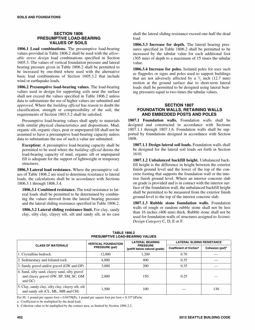
VALUES OF SOILS1806.1 Load combinations. The presumptive load-bearingvalues provided in Table 1806.2 shall be used with the allow-able stress design load combinations specified in Section1605.3. The values of vertical foundation pressure and lateralbearing pressure given in Table 1806.2 shall be permitted tobe increased by one-third where used with the alternativebasic load combinations of Section 1605.3.2 that includewind or earthquake loads.
1806.2 Presumptive load-bearing values. The load-bearingvalues used in design for supporting soils near the surfaceshall not exceed the values specified in Table 1806.2 unlessdata to substantiate the use of higher values are submitted andapproved. Where the building official has reason to doubt theclassification, strength or compressibility of the soil, therequirements of Section 1803.5.2 shall be satisfied.
Presumptive load-bearing values shall apply to materialswith similar physical characteristics and dispositions. Mud,organic silt, organic clays, peat or unprepared fill shall not beassumed to have a presumptive load-bearing capacity unlessdata to substantiate the use of such a value are submitted.
Exception: A presumptive load-bearing capacity shall bepermitted to be used where the building official deems theload-bearing capacity of mud, organic silt or unpreparedfill is adequate for the support of lightweight or temporarystructures.
1806.3 Lateral load resistance. Where the presumptive val-ues of Table 1806.2 are used to determine resistance to lateralloads, the calculations shall be in accordance with Sections1806.3.1 through 1806.3.4.
1806.3.1 Combined resistance. The total resistance to lat-eral loads shall be permitted to be determined by combin-ing the values derived from the lateral bearing pressureand the lateral sliding resistance specified in Table 1806.2.
1806.3.2 Lateral sliding resistance limit. For clay, sandyclay, silty clay, clayey silt, silt and sandy silt, in no case
shall the lateral sliding resistance exceed one-half the deadload.
1806.3.3 Increase for depth. The lateral bearing pres-sures specified in Table 1806.2 shall be permitted to beincreased by the tabular value for each additional foot(305 mm) of depth to a maximum of 15 times the tabularvalue.
1806.3.4 Increase for poles. Isolated poles for uses suchas flagpoles or signs and poles used to support buildingsthat are not adversely affected by a 1/2 inch (12.7 mm)motion at the ground surface due to short-term lateralloads shall be permitted to be designed using lateral bear-ing pressures equal to two times the tabular values.
SECTION 1807 FOUNDATION WALLS, RETAINING WALLS
AND EMBEDDED POSTS AND POLES1807.1 Foundation walls. Foundation walls shall bedesigned and constructed in accordance with Sections1807.1.1 through 1807.1.6. Foundation walls shall be sup-ported by foundations designed in accordance with Section1808.
1807.1.1 Design lateral soil loads. Foundation walls shallbe designed for the lateral soil loads set forth in Section1610.
1807.1.2 Unbalanced backfill height. Unbalanced back-fill height is the difference in height between the exteriorfinish ground level and the lower of the top of the con-crete footing that supports the foundation wall or the inte-rior finish ground level. Where an interior concrete slabon grade is provided and is in contact with the interior sur-face of the foundation wall, the unbalanced backfill heightshall be permitted to be measured from the exterior finishground level to the top of the interior concrete slab.
1807.1.3 Rubble stone foundation walls. Foundationwalls of rough or random rubble stone shall not be lessthan 16 inches (406 mm) thick. Rubble stone shall not beused for foundation walls of structures assigned to SeismicDesign Category C, D, E or F.
TABLE 1806.2PRESUMPTIVE LOAD-BEARING VALUES
For SI: 1 pound per square foot = 0.0479kPa, 1 pound per square foot per foot = 0.157 kPa/m.a. Coefficient to be multiplied by the dead load.b. Cohesion value to be multiplied by the contact area, as limited by Section 1806.3.2.
CLASS OF MATERIALS VERTICAL FOUNDATION PRESSURE (psf)
LATERAL BEARING PRESSURE
(psf/ft below natural grade)
LATERAL SLIDING RESISTANCE
Coefficient of frictiona Cohesion (psf)b
1. Crystalline bedrock 12,000 1,200 0.70 —
2. Sedimentary and foliated rock 4,000 400 0.35 —
3. Sandy gravel and/or gravel (GW and GP) 3,000 200 0.35 —
4. Sand, silty sand, clayey sand, silty gravel and clayey gravel (SW, SP, SM, SC, GM and GC)
2,000 150 0.25 —
5. Clay, sandy clay, silty clay, clayey silt, silt and sandy silt (CL, ML, MH and CH)
1,500 100 — 130
18_Seattle_Build_2012.fm Page 452 Wednesday, November 13, 2013 8:52 AM

SOILS AND FOUNDATIONS
2012 SEATTLE BUILDING CODE 453
1807.1.4 Permanent wood foundation systems. Perma-nent wood foundation systems shall be designed andinstalled in accordance with AF&PA PWF. Lumber andplywood shall be treated in accordance with AWPA U1(Commodity Specification A, Use Category 4B and Sec-tion 5.2) and shall be identified in accordance with Section2303.1.8.1.
1807.1.5 Concrete and masonry foundation walls. Con-crete and masonry foundation walls shall be designed inaccordance with Chapter 19 or 21, as applicable.
Exception: Concrete and masonry foundation wallsshall be permitted to be designed and constructed inaccordance with Section 1807.1.6.
1807.1.6 Prescriptive design of concrete and masonryfoundation walls. Concrete and masonry foundation wallsthat are laterally supported at the top and bottom shall bepermitted to be designed and constructed in accordancewith this section.
1807.1.6.1 Foundation wall thickness. The thicknessof prescriptively designed foundation walls shall not beless than the thickness of the wall supported, exceptthat foundation walls of at least 8-inch (203 mm) nomi-nal width shall be permitted to support brick-veneeredframe walls and 10-inch-wide (254 mm) cavity wallsprovided the requirements of Section 1807.1.6.2 or1807.1.6.3 are met.
1807.1.6.2 Concrete foundation walls. Concrete foun-dation walls shall comply with the following:
1. The thickness shall comply with the requirementsof Table 1807.1.6.2.
2. The size and spacing of vertical reinforcementshown in Table 1807.1.6.2 is based on the use ofreinforcement with a minimum yield strength of60,000 pounds per square inch (psi) (414 MPa).Vertical reinforcement with a minimum yieldstrength of 40,000 psi (276 MPa) or 50,000 psi(345 MPa) shall be permitted, provided the same
TABLE 1807.1.6.2 CONCRETE FOUNDATION WALLSb, c
For SI: 1 inch = 25.4 mm, 1 foot = 304.8 mm, 1 pound per square foot per foot = 0.157 kPa/m.a. For design lateral soil loads, see Section 1610.b. Provisions for this table are based on design and construction requirements specified in Section 1807.1.6.2.c. “PC” means plain concrete.d. Where unbalanced backfill height exceeds 8 feet and design lateral soil loads from Table 1610.1 are used, the requirements for 30 and 45 psf per foot of depth
are not applicable (see Section 1610).e. For height of unbalanced backfill, see Section 1807.1.2.
MAXIMUM WALL
HEIGHT (feet)
MAXIMUM UNBALANCED
BACKFILL HEIGHTe (feet)
MINIMUM VERTICAL REINFORCEMENT-BAR SIZE AND SPACING (inches)
Design lateral soil loada (psf per foot of depth)
30d 45d 60
Minimum wall thickness (inches)
7.5 9.5 11.5 7.5 9.5 11.5 7.5 9.5 11.5
545
PCPC
PCPC
PCPC
PCPC
PCPC
PCPC
PCPC
PCPC
PC PC
6456
PCPCPC
PCPCPC
PCPCPC
PCPCPC
PCPCPC
PCPCPC
PCPCPC
PCPCPC
PCPCPC
7
4567
PCPCPCPC
PCPCPCPC
PCPCPCPC
PCPCPC
#5 at 46
PCPCPCPC
PCPCPCPC
PCPC
#5 at 48#6 at 48
PCPCPCPC
PCPCPCPC
8
45678
PCPCPCPC
#5 at 47
PCPCPCPCPC
PCPCPCPCPC
PCPCPC
#5 at 41#6 at 43
PCPCPCPCPC
PCPCPCPCPC
PCPC
#5 at 43#6 at 43#6 at 32
PCPCPCPC
#6 at 44
PCPCPCPCPC
9
456789d
PCPCPCPC
#5 at 41#6 at 46
PCPCPCPCPCPC
PCPCPCPCPCPC
PCPCPC
#5 at 37#6 at 38#7 at 41
PCPCPCPC
#5 at 37#6 at 41
PCPCPCPCPCPC
PCPC
#5 at 39#6 at 38#7 at 39#7 at 31
PCPCPC
#5 at 37#6 at 39#7 at 41
PCPCPCPC
#4 at 48#6 at 39
10
456789d
10d
PCPCPCPC
#5 at 38#6 at 41#7 at 45
PCPCPCPCPC
#4 at 48#6 at 45
PCPCPCPCPCPCPC
PCPCPC
#6 at 48#7 at 47#7 at 37#7 at 31
PCPCPCPC
#6 at 47#7 at 48#7 at 40
PCPCPCPCPC
#4 at 48#6 at 38
PCPC
#5 at 37#6 at 35#7 at 35#6 at 22#6 at 22
PCPCPC
#6 at 48#7 at 47#7 at 37#7 at 30
PCPCPCPC
#6 at 45#7 at 47#7 at 38
18_Seattle_Build_2012.fm Page 453 Wednesday, November 13, 2013 8:52 AM

SOILS AND FOUNDATIONS
454 2012 SEATTLE BUILDING CODE
size bar is used and the spacing shown in thetable is reduced by multiplying the spacing by0.67 or 0.83, respectively.
3. Vertical reinforcement, when required, shall beplaced nearest the inside face of the wall a dis-tance, d, from the outside face (soil face) of thewall. The distance, d, is equal to the wall thick-ness, t, minus 1.25 inches (32 mm) plus one-halfthe bar diameter, db, [ d = t - (1.25 + db / 2) ]. Thereinforcement shall be placed within a tolerance of± 3/8 inch (9.5 mm) where d is less than or equal to8 inches (203 mm) or ± 1/2 inch (12.7 mm) where dis greater than 8 inches (203 mm).
4. In lieu of the reinforcement shown in Table1807.1.6.2, smaller reinforcing bar sizes withcloser spacings that provide an equivalent cross-sectional area of reinforcement per unit lengthshall be permitted.
5. Concrete cover for reinforcement measured fromthe inside face of the wall shall not be less than 3/4
inch (19.1 mm). Concrete cover for reinforcementmeasured from the outside face of the wall shallnot be less than 11/2 inches (38 mm) for No. 5 barsand smaller, and not less than 2 inches (51 mm)for larger bars.
6. Concrete shall have a specified compressivestrength, f ′c, of not less than 2,500 psi (17.2MPa).
7. The unfactored axial load per linear foot of wallshall not exceed 1.2 t f ′c where t is the specifiedwall thickness in inches.
1807.1.6.2.1 Seismic requirements. Based on theseismic design category assigned to the structure inaccordance with Section 1613, concrete foundationwalls designed using Table 1807.1.6.2 shall be sub-ject to the following limitations:
1. Seismic Design Categories A and B. Not lessthan one No. 5 bar shall be provided aroundwindow, door and similar sized openings. Thebar shall be anchored to develop fy in tensionat the corners of openings.
2. Seismic Design Categories C, D, E and F.Tables shall not be used except as allowed forplain concrete members in Section 1905.1.8.
1807.1.6.3 Masonry foundation walls. Masonry foun-dation walls shall comply with the following:
1. The thickness shall comply with the require-ments of Table 1807.1.6.3(1) for plain masonrywalls or Table 1807.1.6.3(2), 1807.1.6.3(3) or1807.1.6.3(4) for masonry walls with reinforce-ment.
2. Vertical reinforcement shall have a minimumyield strength of 60,000 psi (414 MPa).
3. The specified location of the reinforcementshall equal or exceed the effective depth dis-tance, d, noted in Tables 1807.1.6.3(2),1807.1.6.3(3) and 1807.1.6.3(4) and shall bemeasured from the face of the exterior (soil)side of the wall to the center of the vertical rein-forcement. The reinforcement shall be placedwithin the tolerances specified in TMS 602/ACI530.1/ASCE 6, Article 3.4.B.8 of the specifiedlocation.
TABLE 1807.1.6.3(1) PLAIN MASONRY FOUNDATION WALLSa, b, c
For SI: 1 inch = 25.4 mm, 1 foot = 304.8 mm, 1 pound per square foot per foot = 0.157 kPa/m.a. For design lateral soil loads, see Section 1610.b. Provisions for this table are based on design and construction requirements specified in Section 1807.1.6.3.c. Solid grouted hollow units or solid masonry units.d. A design in compliance with Chapter 21 or reinforcement in accordance with Table 1807.1.6.3(2) is required.e. For height of unbalanced backfill, see Section 1807.1.2.f. Where unbalanced backfill height exceeds 8 feet and design lateral soil loads from Table 1610.1 are used, the requirements for 30 and 45 psf per foot of depth
are not applicable (see Section 1610).
MAXIMUM WALL HEIGHT (feet)
MAXIMUM UNBALANCED BACKFILL HEIGHTe (feet)
MINIMUM NOMINAL WALL THICKNESS (inches)
Design lateral soil loada (psf per foot of depth)
30f 45f 60
7
4 (or less)567
88
1012
81012
10 (solidc)
810
10 (solidc)10 (solidc)
8
4 (or less)5678
88
1012
10 (solidc)
81012
12 (solidc)12 (solidc)
812
12 (solidc)Note dNote d
9
4 (or less)56789f
88
1212 (solidc)12 (solidc)
Note d
81012
12 (solidc)Note dNote d
812
12 (solidc)Note dNote dNote d
18_Seattle_Build_2012.fm Page 454 Wednesday, November 13, 2013 8:52 AM

SOILS AND FOUNDATIONS
2012 SEATTLE BUILDING CODE 455
4. Grout shall comply with Section 2103.13.
5. Concrete masonry units shall comply withASTM C 90.
6. Clay masonry units shall comply with ASTM C652 for hollow brick, except compliance withASTM C 62 or ASTM C 216 shall be permittedwhere solid masonry units are installed inaccordance with Table 1807.1.6.3(1) for plainmasonry.
7. Masonry units shall be laid in running bond andinstalled with Type M or S mortar in accor-dance with Section 2103.9.
8. The unfactored axial load per linear foot of wallshall not exceed 1.2 t f ′m where t is the specifiedwall thickness in inches and f ′m is the specified
compressive strength of masonry in pounds persquare inch.
9. At least 4 inches (102 mm) of solid masonryshall be provided at girder supports at the top ofhollow masonry unit foundation walls.
10. Corbeling of masonry shall be in accordancewith Section 2104.2. Where an 8-inch (203mm) wall is corbeled, the top corbel shall notextend higher than the bottom of the floor fram-ing and shall be a full course of headers at least6 inches (152 mm) in length or the top coursebed joint shall be tied to the vertical wall projec-tion. The tie shall be W2.8 (4.8 mm) and spacedat a maximum horizontal distance of 36 inches(914 mm). The hollow space behind the cor-belled masonry shall be filled with mortar orgrout.
TABLE 1807.1.6.3(2)8-INCH MASONRY FOUNDATION WALLS WITH REINFORCEMENT WHERE d ≥ 5 INCHESa, b, c
For SI: 1 inch = 25.4 mm, 1 foot = 304.8 mm, 1 pound per square foot per foot = 0.157 kPa/m.a. For design lateral soil loads, see Section 1610.b. Provisions for this table are based on design and construction requirements specified in Section 1807.1.6.3.c. For alternative reinforcement, see Section 1807.1.6.3.1d. For height of unbalanced backfill, see Section 1807.1.2e. Where unbalanced backfill height exceeds 8 feet and design lateral soil loads from Table 1610.1 are used, the requirements for 30 and 45 psf per foot of depth
are not applicable. See Section 1610.
MAXIMUM WALL HEIGHT (feet-inches)
MAXIMUM UNBALANCED BACKFILL HEIGHTd
(feet-inches)
MINIMUM VERTICAL REINFORCEMENT-BAR SIZE AND SPACING (inches)
Design lateral soil loada
(psf per foot of depth)
30e 45e 60
7-4
4-0 (or less)5-06-07-4
#4 at 48#4 at 48#4 at 48#5 at 48
#4 at 48#4 at 48#5 at 48#6 at 48
#4 at 48#4 at 48#5 at 48#7 at 48
8-0
4-0 (or less) 5-06-07-08-0
#4 at 48#4 at 48#4 at 48#5 at 48#5 at 48
#4 at 48#4 at 48#5 at 48#6 at 48#6 at 48
#4 at 48#4 at 48#5 at 48#7 at 48#7 at 48
8-8
4-0 (or less)5-06-07-08-8e
#4 at 48#4 at 48#4 at 48#5 at 48#6 at 48
#4 at 48#4 at 48#5 at 48#6 at 48#7 at 48
#4 at 48#5 at 48#6 at 48#7 at 48#8 at 48
9-4
4-0 (or less)5-06-07-08-09-4e
#4 at 48#4 at 48#4 at 48#5 at 48#6 at 48#7 at 48
#4 at 48#4 at 48#5 at 48#6 at 48#7 at 48#8 at 48
#4 at 48#5 at 48#6 at 48#7 at 48#8 at 48#9 at 48
10-0
4-0 (or less)5-06-07-08-09-0e
10-0e
#4 at 48#4 at 48#4 at 48#5 at 48#6 at 48#7 at 48#7 at 48
#4 at 48#4 at 48#5 at 48#6 at 48#7 at 48#8 at 48#9 at 48
#4 at 48#5 at 48#6 at 48#7 at 48#8 at 48#9 at 48#9 at 48
18_Seattle_Build_2012.fm Page 455 Wednesday, November 13, 2013 8:52 AM

SOILS AND FOUNDATIONS
456 2012 SEATTLE BUILDING CODE
TABLE 1807.1.6.3(3) 10-INCH MASONRY FOUNDATION WALLS WITH REINFORCEMENT WHERE d ≥ 6.75 INCHES a, b, c
For SI: 1 inch = 25.4 mm, 1 foot = 304.8, 1 pound per square foot per foot = 1.157 kPa/m.a. For design lateral soil loads, see Section 1610.b. Provisions for this table are based on design and construction requirements specified in Section 1807.1.6.3c. For alternative reinforcement, see Section 1807.1.6.3.1.d. For height of unbalanced backfill, See Section 1807.1.2.e. Where unbalanced backfill height exceeds 8 feet and design lateral soil loads from Table 1610.1 are used, the requirements for 30 and 45 psf per foot of depth
are not applicable. See Section 1610.
MAXIMUM WALL HEIGHT (feet-inches)
MAXIMUM UNBALANCED BACKFILL HEIGHTd
(feet-inches)
MINIMUM VERTICAL REINFORCEMENT-BAR SIZE AND SPACING (inches)
Design lateral soil loada (psf per foot of depth)
30e 45e 60
7-4
4-0 (or less)5-06-07-4
#4 at 56#4 at 56#4 at 56#4 at 56
#4 at 56#4 at 56#4 at 56#5 at 56
#4 at 56#4 at 56#5 at 56#6 at 56
8-0
4-0 (or less) 5-06-07-08-0
#4 at 56#4 at 56#4 at 56#4 at 56#5 at 56
#4 at 56#4 at 56#4 at 56#5 at 56#6 at 56
#4 at 56#4 at 56#5 at 56#6 at 56#7 at 56
8-8
4-0 (or less)5-06-07-08-8e
#4 at 56#4 at 56#4 at 56#4 at 56#5 at 56
#4 at 56#4 at 56#4 at 56#5 at 56#7 at 56
#4 at 56#4 at 56#5 at 56#6 at 56#8 at 56
9-4
4-0 (or less)5-06-07-08-09-4e
#4 at 56#4 at 56#4 at 56#4 at 56#5 at 56#6 at 56
#4 at 56#4 at 56#5 at 56#5 at 56#6 at 56#7 at 56
#4 at 56#4 at 56#5 at 56#6 at 56#7 at 56#7 at 56
10-0
4-0 (or less)5-06-07-08-09-0e
10-0e
#4 at 56#4 at 56#4 at 56#5 at 56#5 at 56#6 at 56#7 at 56
#4 at 56#4 at 56#5 at 56#6 at 56#7 at 56#7 at 56#8 at 56
#4 at 56#4 at 56#5 at 56#7 at 56#8 at 56#9 at 56#9 at 56
18_Seattle_Build_2012.fm Page 456 Wednesday, November 13, 2013 8:52 AM

SOILS AND FOUNDATIONS
2012 SEATTLE BUILDING CODE 457
1807.1.6.3.1 Alternative foundation wall rein-forcement. In lieu of the reinforcement provisionsfor masonry foundation walls in Table1807.1.6.3(2), 1807.1.6.3(3) or 1807.1.6.3(4), alter-native reinforcing bar sizes and spacings having anequivalent cross-sectional area of reinforcement perlinear foot (mm) of wall shall be permitted to beused, provided the spacing of reinforcement doesnot exceed 72 inches (1829 mm) and reinforcing barsizes do not exceed No. 11.
1807.1.6.3.2 Seismic requirements. Based on theseismic design category assigned to the structure inaccordance with Section 1613, masonry foundationwalls designed using Tables 1807.1.6.3(1) through1807.1.6.3(4) shall be subject to the following limi-tations:
1. Seismic Design Categories A and B. No addi-tional seismic requirements.
2. Seismic Design Category C. A design usingTables 1807.1.6.3(1) through 1807.1.6.3(4) is
subject to the seismic requirements of Section1.18.4.3 of TMS 402/ACI 530/ASCE 5.
3. Seismic Design Category D. A design usingTables 1807.1.6.3(2) through 1807.1.6.3(4) issubject to the seismic requirements of Section1.18.4.4 of TMS 402/ACI 530/ASCE 5.
4. Seismic Design Categories E and F. A designusing Tables 1807.1.6.3(2) through1807.1.6.3(4) is subject to the seismic require-ments of Section 1.18.4.5 of TMS 402/ACI530/ASCE 5.
1807.2 Retaining walls. Retaining walls shall be designed inaccordance with Sections 1807.2.1 through 1807.2.3.
1807.2.1 General. Retaining walls shall be designed toensure stability against overturning, sliding, excessivefoundation pressure and water uplift. Where a keyway isextended below the wall base with the intent to engagepassive pressure and enhance sliding stability, lateral soilpressures on both sides of the keyway shall be consideredin the sliding analysis.
TABLE 1807.1.6.3(4)12-INCH MASONRY FOUNDATION WALLS WITH REINFORCEMENT WHERE d ≥ 8.75 INCHESa, b, c
For SI: 1 inch = 25.4 mm, 1 foot = 304.8 mm, 1 pound per square foot per foot = 0.157 kPa/m.a. For design lateral soil loads, see Section 1610.b. Provisions for this table are based on design and construction requirements specified in Section 1807.1.6.3.c. For alternative reinforcement, see Section 1807.1.6.3.1.d. For height of unbalanced backfill, see Section 1807.1.2.e Where unbalanced backfill height exceeds 8 feet and design lateral soil loads from Table 1610.1 are used, the requirements for 30 and 45 psf per foot of depth
are not applicable. See Section 1610.
MAXIMUM WALL HEIGHT (feet-inches)
MAXIMUM UNBALANCED BACKFILL HEIGHTd
(feet-inches)
MINIMUM VERTICAL REINFORCEMENT-BAR SIZE AND SPACING (inches)
Design lateral soil loada (psf per foot of depth)
30e 45e 60
7-4
4 (or less)5-06-07-4
#4 at 72#4 at 72#4 at 72#4 at 72
#4 at 72#4 at 72#4 at 72#5 at 72
#4 at 72#4 at 72#5 at 72#6 at 72
8-0
4 (or less) 5-06-07-08-0
#4 at 72#4 at 72#4 at 72#4 at 72#5 at 72
#4 at 72#4 at 72#4 at 72#5 at 72#6 at 72
#4 at 72#4 at 72#5 at 72#6 at 72#8 at 72
8-8
4 (or less)5-06-07-08-8e
#4 at 72#4 at 72#4 at 72#4 at 72#5 at 72
#4 at 72#4 at 72#4 at 72#5 at 72#7 at 72
#4 at 72#4 at 72#5 at 72#6 at 72#8 at 72
9-4
4 (or less)5-06-07-08-09-4e
#4 at 72#4 at 72#4 at 72#4 at 72#5 at 72#6 at 72
#4 at 72#4 at 72#5 at 72#5 at 72#6 at 72#7 at 72
#4 at 72#4 at 72#5 at 72#6 at 72#7 at 72#8 at 72
10-0
4 (or less)5-06-07-08-09-0e
10-0e
#4 at 72#4 at 72#4 at 72#4 at 72#5 at 72#6 at 72#7 at 72
#4 at 72#4 at 72#5 at 72#6 at 72#6 at 72#7 at 72#8 at 72
#4 at 72#4 at 72#5 at 72#6 at 72#7 at 72#8 at 72#9 at 72
18_Seattle_Build_2012.fm Page 457 Wednesday, November 13, 2013 8:52 AM

SOILS AND FOUNDATIONS
458 2012 SEATTLE BUILDING CODE
1807.2.2 Design lateral soil loads. Retaining walls shallbe designed for the lateral soil loads set forth in Section1610.
1807.2.3 Safety factor. Retaining walls shall be designedto resist the lateral action of soil to produce sliding andoverturning with a minimum safety factor of 1.5 in eachcase. The load combinations of Section 1605 shall notapply to this requirement. Instead, design shall be based on0.7 times nominal earthquake loads, 1.0 times other nomi-nal loads, and investigation with one or more of the vari-able loads set to zero. The safety factor against lateralsliding shall be taken as the available soil resistance at thebase of the retaining wall foundation divided by the netlateral force applied to the retaining wall.
Exception: Where earthquake loads are included, theminimum safety factor for retaining wall sliding andoverturning shall be 1.1.
1807.3 Embedded posts and poles. Designs to resist bothaxial and lateral loads employing posts or poles as columnsembedded in earth or in concrete footings in earth shall be inaccordance with Sections 1807.3.1 through 1807.3.3.
1807.3.1 Limitations. The design procedures outlined inthis section are subject to the following limitations:
1. The frictional resistance for structural walls andslabs on silts and clays shall be limited to one-half ofthe normal force imposed on the soil by the weightof the footing or slab.
2. Posts embedded in earth shall not be used to providelateral support for structural or nonstructural materi-als such as plaster, masonry or concrete unless brac-ing is provided that develops the limited deflectionrequired.
Wood poles shall be treated in accordance with AWPAU1 for sawn timber posts (Commodity Specification A,Use Category 4B) and for round timber posts (CommoditySpecification B, Use Category 4B).
1807.3.2 Design criteria. The depth to resist lateral loadsshall be determined using the design criteria established inSections 1807.3.2.1 through 1807.3.2.3, or by other meth-ods approved by the building official.
1807.3.2.1 Nonconstrained. The following formulashall be used in determining the depth of embedmentrequired to resist lateral loads where no lateral con-straint is provided at the ground surface, such as by arigid floor or rigid ground surface pavement, and whereno lateral constraint is provided above the ground sur-face, such as by a structural diaphragm.
d = 0.5A{1 + [1 + (4.36h/A)]1/2} (Equation 18-1)
where:
A = 2.34P/(S1b)
b = Diameter of round post or footing or diagonaldimension of square post or footing, feet (m).
d = Depth of embedment in earth in feet (m) but notover 12 feet (3.658 m) for purpose of computinglateral pressure.
h = Distance in feet (m) from ground surface to pointof application of “P.”
P = Applied lateral force in pounds (kN).
S1 = Allowable lateral soil-bearing pressure as setforth in Section 1806.2 based on a depth of one-third the depth of embedment in pounds persquare foot (psf) (kPa).
1807.3.2.2 Constrained. The following formula shallbe used to determine the depth of embedment requiredto resist lateral loads where lateral constraint is pro-vided at the ground surface, such as by a rigid floor orpavement.
(Equation 18-2)
or alternatively
(Equation 18-3)
where:
Mg = Moment in the post at grade, in foot-pounds (kN-m).
S3 = Allowable lateral soil-bearing pressure as setforth in Section 1806.2 based on a depth equal tothe depth of embedment in pounds per squarefoot (kPa).
1807.3.2.3 Vertical load. The resistance to verticalloads shall be determined using the vertical foundationpressure set forth in Table 1806.2.
1807.3.3 Backfill. The backfill in the annular spacearound columns not embedded in poured footings shall beby one of the following methods:
1. Backfill shall be of concrete with a specified com-pressive strength of not less than 2,000 psi (13.8MPa). The hole shall not be less than 4 inches (102mm) larger than the diameter of the column at itsbottom or 4 inches (102 mm) larger than the diago-nal dimension of a square or rectangular column.
2. Backfill shall be of clean sand.The sand shall bethoroughly compacted by tamping in layers notmore than 8 inches (203 mm) in depth.
3. Backfill shall be of controlled low-strength material(CLSM).
SECTION 1808 FOUNDATIONS
1808.1 General. Foundations shall be designed and con-structed in accordance with Sections 1808.2 through 1808.9.Shallow foundations shall also satisfy the requirements ofSection 1809. Deep foundations shall also satisfy the require-ments of Section 1810.
1808.2 Design for capacity and settlement. Foundationsshall be so designed that the allowable bearing capacity of thesoil is not exceeded, and that differential settlement is mini-
d 4.25PhS3b
-----------------=
d4.25Mg
S3b------------------=
18_Seattle_Build_2012.fm Page 458 Wednesday, November 13, 2013 8:52 AM

SOILS AND FOUNDATIONS
2012 SEATTLE BUILDING CODE 459
mized. Foundations in areas with expansive soils shall bedesigned in accordance with the provisions of Section1808.6.
1808.3 Design loads. Foundations shall be designed for themost unfavorable effects due to the combinations of loadsspecified in Section 1605.2 or 1605.3. The dead load is per-mitted to include the weight of foundations and overlying fill.Reduced live loads, as specified in Sections 1607.10 and1607.12, shall be permitted to be used in the design of foun-dations.
1808.3.1 Seismic overturning. Where foundations areproportioned using the load combinations of Section1605.2 or 1605.3.1, and the computation of seismic over-turning effects is by equivalent lateral force analysis ormodal analysis, the proportioning shall be in accordancewith Section 12.13.4 of ASCE 7.
1808.4 Vibratory loads. Where machinery operations orother vibrations are transmitted through the foundation, con-sideration shall be given in the foundation design to preventdetrimental disturbances of the soil.
1808.5 Shifting or moving soils. Where it is known that theshallow subsoils are of a shifting or moving character, foun-dations shall be carried to a sufficient depth to ensure stabil-ity.
1808.6 Design for expansive soils. Foundations for buildingsand structures founded on expansive soils shall be designedin accordance with Section 1808.6.1 or 1808.6.2.
Exception: Foundation design need not comply with Sec-tion 1808.6.1 or 1808.6.2 where one of the following con-ditions is satisfied:
1. The soil is removed in accordance with Section1808.6.3; or
2. The building official approves stabilization of thesoil in accordance with Section 1808.6.4.
1808.6.1 Foundations. Foundations placed on or withinthe active zone of expansive soils shall be designed toresist differential volume changes and to prevent structuraldamage to the supported structure. Deflection and rackingof the supported structure shall be limited to that whichwill not interfere with the usability and serviceability ofthe structure.
Foundations placed below where volume changeoccurs or below expansive soil shall comply with the fol-lowing provisions:
1. Foundations extending into or penetrating expansivesoils shall be designed to prevent uplift of the sup-ported structure.
2. Foundations penetrating expansive soils shall bedesigned to resist forces exerted on the foundationdue to soil volume changes or shall be isolated fromthe expansive soil.
1808.6.2 Slab-on-ground foundations. Moments, shearsand deflections for use in designing slab-on-ground, mator raft foundations on expansive soils shall be determinedin accordance with WRI/CRSI Design of Slab-on-GroundFoundations or PTI Standard Requirements for Analysis
of Shallow Concrete Foundations on Expansive Soils.Using the moments, shears and deflections determinedabove, nonprestressed slabs-on-ground, mat or raft foun-dations on expansive soils shall be designed in accordancewith WRI/CRSI Design of Slab-on-Ground Foundationsand post-tensioned slab-on-ground, mat or raft founda-tions on expansive soils shall be designed in accordancewith PTI Standard Requirements for Design of ShallowPost-Tensioned Concrete Foundations on Expansive Soils.It shall be permitted to analyze and design such slabs byother methods that account for soil-structure interaction,the deformed shape of the soil support, the plate or stiff-ened plate action of the slab as well as both center lift andedge lift conditions. Such alternative methods shall berational and the basis for all aspects and parameters of themethod shall be available for peer review.
1808.6.3 Removal of expansive soil. Where expansivesoil is removed in lieu of designing foundations in accor-dance with Section 1808.6.1 or 1808.6.2, the soil shall beremoved to a depth sufficient to ensure a constant moisturecontent in the remaining soil. Fill material shall not con-tain expansive soils and shall comply with Section 1804.5or 1804.6.
Exception: Expansive soil need not be removed to thedepth of constant moisture, provided the confiningpressure in the expansive soil created by the fill andsupported structure exceeds the swell pressure.
1808.6.4 Stabilization. Where the active zone of expan-sive soils is stabilized in lieu of designing foundations inaccordance with Section 1808.6.1 or 1808.6.2, the soilshall be stabilized by chemical, dewatering, presaturationor equivalent techniques.
((1808.7 Foundations on or adjacent to slopes. The place-ment of buildings and structures on or adjacent to slopessteeper than one unit vertical in three units horizontal (33.3-percent slope) shall comply with Sections 1808.7.1 through1808.7.5.
1808.7.1 Building clearance from ascending slopes. Ingeneral, buildings below slopes shall be set a sufficientdistance from the slope to provide protection from slopedrainage, erosion and shallow failures. Except as providedin Section 1808.7.5 and Figure 1808.7.1, the following cri-teria will be assumed to provide this protection. Where theexisting slope is steeper than one unit vertical in one unithorizontal (100-percent slope), the toe of the slope shall beassumed to be at the intersection of a horizontal planedrawn from the top of the foundation and a plane drawntangent to the slope at an angle of 45 degrees (0.79 rad) tothe horizontal. Where a retaining wall is constructed at thetoe of the slope, the height of the slope shall be measuredfrom the top of the wall to the top of the slope.
1808.7.2 Foundation setback from descending slopesurface. Foundations on or adjacent to slope surfaces shallbe founded in firm material with an embedment and setback from the slope surface sufficient to provide verticaland lateral support for the foundation without detrimentalsettlement. Except as provided for in Section 1808.7.5 andFigure 1808.7.1, the following setback is deemed adequate
18_Seattle_Build_2012.fm Page 459 Wednesday, November 13, 2013 8:52 AM

SOILS AND FOUNDATIONS
460 2012 SEATTLE BUILDING CODE
to meet the criteria. Where the slope is steeper than 1 unitvertical in 1 unit horizontal (100-percent slope), therequired setback shall be measured from an imaginaryplane 45 degrees (0.79 rad) to the horizontal, projectedupward from the toe of the slope.
1808.7.3 Pools. The setback between pools regulated bythis code and slopes shall be equal to one-half the buildingfooting setback distance required by this section. That por-tion of the pool wall within a horizontal distance of 7 feet(2134 mm) from the top of the slope shall be capable ofsupporting the water in the pool without soil support.
1808.7.4 Foundation elevation. On graded sites, the topof any exterior foundation shall extend above the elevationof the street gutter at point of discharge or the inlet of anapproved drainage device a minimum of 12 inches (305mm) plus 2 percent. Alternate elevations are permittedsubject to the approval of the building official, provided itcan be demonstrated that required drainage to the point ofdischarge and away from the structure is provided at alllocations on the site.
1808.7.5 Alternate setback and clearance. Alternate set-backs and clearances are permitted, subject to the approvalof the building official. The building official shall be per-
mitted to require a geotechnical investigation as set forthin Section 1803.5.10.))
1808.8 Concrete foundations. The design, materials andconstruction of concrete foundations shall comply with Sec-tions 1808.8.1 through 1808.8.6 and the provisions of Chap-ter 19.
Exception: Where concrete footings supporting walls oflight-frame construction are designed in accordance withTable 1809.7, a specific design in accordance with Chap-ter 19 is not required.
1808.8.1 Concrete or grout strength and mix propor-tioning. Concrete or grout in foundations shall have aspecified compressive strength (f ′c) not less than the larg-est applicable value indicated in Table 1808.8.1.
Where concrete is placed through a funnel hopper at thetop of a deep foundation element, the concrete mix shallbe designed and proportioned so as to produce a cohesiveworkable mix having a slump of not less than 4 inches(102 mm) and not more than 8 inches (204 mm). Whereconcrete or grout is to be pumped, the mix design includ-ing slump shall be adjusted to produce a pumpable mix-ture.
TABLE 1808.8.1 MINIMUM SPECIFIED COMPRESSIVE STRENGTH f ′C OF CONCRETE OR GROUT
For SI:1 pound per square inch = 0.00689 MPa.
FOUNDATION ELEMENT OR CONDITION SPECIFIED COMPRESSIVE STRENGTH, f ′c
1. Foundations for structures assigned to Seismic Design Category A, B or C 2,500 psi
2a. Foundations for Group R or U occupancies of light-frame construction, two stories or less in height, assigned to Seismic Design Category D, E or F
2,500 psi
2b. Foundations for other structures assigned to Seismic Design Category D, E or F 3,000 psi
3. Precast nonprestressed driven piles 4,000 psi
4. Socketed drilled shafts 4,000 psi
5. Micropiles 4,000 psi
6. Precast prestressed driven piles 5,000 psi
For SI: 1 foot = 304.8 mm.
FIGURE 1808.7.1 FOUNDATION CLEARANCES FROM SLOPES
18_Seattle_Build_2012.fm Page 460 Wednesday, November 13, 2013 8:52 AM

SOILS AND FOUNDATIONS
2012 SEATTLE BUILDING CODE 461
1808.8.2 Concrete cover. The concrete cover providedfor prestressed and nonprestressed reinforcement in foun-dations shall be no less than the largest applicable valuespecified in Table 1808.8.2. Longitudinal bars spaced lessthan 11/2 inches (38 mm) clear distance apart shall be con-sidered bundled bars for which the concrete cover pro-vided shall also be no less than that required by Section7.7.4 of ACI 318. Concrete cover shall be measured fromthe concrete surface to the outermost surface of the steel towhich the cover requirement applies. Where concrete isplaced in a temporary or permanent casing or a mandrel,the inside face of the casing or mandrel shall be consideredthe concrete surface.
1808.8.3 Placement of concrete. Concrete shall be placedin such a manner as to ensure the exclusion of any foreignmatter and to secure a full-size foundation. Concrete shallnot be placed through water unless a tremie or othermethod approved by the building official is used. Whereplaced under or in the presence of water, the concrete shallbe deposited by approved means to ensure minimum seg-regation of the mix and negligible turbulence of the water.Where depositing concrete from the top of a deep founda-tion element, the concrete shall be chuted directly intosmooth-sided pipes or tubes or placed in a rapid and con-tinuous operation through a funnel hopper centered at thetop of the element.
1808.8.4 Protection of concrete. Concrete foundationsshall be protected from freezing during depositing and fora period of not less than five days thereafter. Water shallnot be allowed to flow through the deposited concrete.
1808.8.5 Forming of concrete. Concrete foundations arepermitted to be cast against the earth where, in the opinionof the building official, soil conditions do not requireformwork. Where formwork is required, it shall be inaccordance with Chapter 6 of ACI 318.
1808.8.6 Seismic requirements. See Section 1908 foradditional requirements for foundations of structuresassigned to Seismic Design Category C, D, E or F.
For structures assigned to Seismic Design Category D,E or F, provisions of ACI 318, Sections 21.12.1 through21.12.4, shall apply where not in conflict with the provi-sions of Sections 1808 through 1810.
Exceptions:
1. Detached one- and two-family dwellings of light-frame construction and two stories or less abovegrade plane are not required to comply with theprovisions of ACI 318, Sections 21.12.1 through21.12.4.
2. Section 21.12.4.4(a) of ACI 318 shall not apply.
1808.9 Vertical masonry foundation elements. Verticalmasonry foundation elements that are not foundation piers asdefined in Section 202 shall be designed as piers, walls orcolumns, as applicable, in accordance with TMS 402/ACI530/ASCE 5.
SECTION 1809 SHALLOW FOUNDATIONS
1809.1 General. Shallow foundations shall be designed andconstructed in accordance with Sections 1809.2 through1809.13.
1809.2 Supporting soils. Shallow foundations shall be builton undisturbed soil, compacted fill material or controlledlow-strength material (CLSM). Compacted fill material shallbe placed in accordance with Section 1804.5. CLSM shall beplaced in accordance with Section 1804.6.
1809.3 Stepped footings. The top surface of footings shall belevel. The bottom surface of footings shall be permitted tohave a slope not exceeding one unit vertical in 10 units hori-zontal (10-percent slope). Footings shall be stepped where itis necessary to change the elevation of the top surface of thefooting or where the surface of the ground slopes more thanone unit vertical in 10 units horizontal (10-percent slope).
1809.4 Depth and width of footings. The minimum depth offootings below the undisturbed ground surface shall be 12
TABLE 1808.8.2MINIMUM CONCRETE COVER
For SI: 1 inch = 25.4 mm.
FOUNDATION ELEMENT OR CONDITION MINIMUM COVER
1. Shallow foundations In accordance with Section 7.7 of ACI 318
2. Precast nonprestressed deep foundation elements Exposed to seawater Not manufactured under plant conditions Manufactured under plant control conditions
3 inches2 inchesIn accordance with Section 7.7.3 of ACI 318
3. Precast prestressed deep foundation elements Exposed to seawater Other
2.5 inchesIn accordance with Section 7.7.3 of ACI 318
4. Cast-in-place deep foundation elements not enclosed by a steel pipe, tube or permanent casing
2.5 inches
5. Cast-in-place deep foundation elements enclosed by a steel pipe, tube or permanent casing 1 inch
6. Structural steel core within a steel pipe, tube or permanent casing 2 inches
7. Cast-in-place drilled shafts enclosed by a stable rock socket 1.5 inches
18_Seattle_Build_2012.fm Page 461 Wednesday, November 13, 2013 8:52 AM

SOILS AND FOUNDATIONS
462 2012 SEATTLE BUILDING CODE
inches (305 mm). Where applicable, the requirements of Sec-tion 1809.5 shall also be satisfied. The minimum width offootings shall be 12 inches (305 mm).
1809.5 Frost protection. Except where otherwise protectedfrom frost, foundations and other permanent supports ofbuildings and structures shall be protected from frost by oneor more of the following methods:
1. Extending below the frost line of the locality;
2. Constructing in accordance with ASCE 32; or
3. Erecting on solid rock.
Exception: Free-standing buildings meeting all of thefollowing conditions shall not be required to be pro-tected:
1. Assigned to Risk Category I, in accordance withSection 1604.5;
2. Area of 600 square feet (56 m2) or less for light-frame construction or 400 square feet (37 m2) orless for other than light-frame construction; and
3. Eave height of 10 feet (3048 mm) or less.
Shallow foundations shall not bear on frozen soil unlesssuch frozen condition is of a permanent character.
1809.6 Location of footings. Footings on granular soil shallbe so located that the line drawn between the lower edges ofadjoining footings shall not have a slope steeper than 30degrees (0.52 rad) with the horizontal, unless the materialsupporting the higher footing is braced or retained or other-wise laterally supported in an approved manner or a greaterslope has been properly established by engineering analysis.
1809.7 Prescriptive footings for light-frame construction.Where a specific design is not provided, concrete or masonry-unit footings supporting walls of light-frame construction shallbe permitted to be designed in accordance with Table 1809.7.
TABLE 1809.7 PRESCRIPTIVE FOOTINGS SUPPORTING WALLS OF
LIGHT-FRAME CONSTRUCTIONa, b, c, d, e
For SI: 1 inch = 25.4 mm, 1 foot = 304.8 mm.a. Depth of footings shall be in accordance with Section 1809.4.b. The ground under the floor shall be permitted to be excavated to the
elevation of the top of the footing.c. Interior stud-bearing walls shall be permitted to be supported by isolated
footings. The footing width and length shall be twice the width shown inthis table, and footings shall be spaced not more than 6 feet on center.
d. See Section 1905 for additional requirements for concrete footings ofstructures assigned to Seismic Design Category C, D, E or F.
e. For thickness of foundation walls, see Section 1807.1.6.f. Footings shall be permitted to support a roof in addition to the stipulated
number of floors. Footings supporting roof only shall be as required forsupporting one floor.
g. Plain concrete footings for Group R-3 occupancies shall be permitted tobe 6 inches thick.
1809.8 Plain concrete footings. The edge thickness of plainconcrete footings supporting walls of other than light-frameconstruction shall not be less than 8 inches (203 mm) whereplaced on soil or rock.
Exception: For plain concrete footings supporting GroupR-3 occupancies, the edge thickness is permitted to be 6inches (152 mm), provided that the footing does notextend beyond a distance greater than the thickness of thefooting on either side of the supported wall.
1809.9 Masonry-unit footings. The design, materials andconstruction of masonry-unit footings shall comply with Sec-tions 1809.9.1 and 1809.9.2, and the provisions of Chapter21.
Exception: Where a specific design is not provided,masonry-unit footings supporting walls of light-frameconstruction shall be permitted to be designed in accor-dance with Table 1809.7.
1809.9.1 Dimensions. Masonry-unit footings shall be laidin Type M or S mortar complying with Section 2103.9 andthe depth shall not be less than twice the projectionbeyond the wall, pier or column. The width shall not beless than 8 inches (203 mm) wider than the wall supportedthereon.
1809.9.2 Offsets. The maximum offset of each course inbrick foundation walls stepped up from the footings shallbe 11/2 inches (38 mm) where laid in single courses, and 3inches (76 mm) where laid in double courses.
1809.10 Pier and curtain wall foundations. Except in Seis-mic Design Categories D, E and F, pier and curtain wallfoundations shall be permitted to be used to support light-frame construction not more than two stories above gradeplane, provided the following requirements are met:
1. All load-bearing walls shall be placed on continuousconcrete footings bonded integrally with the exteriorwall footings.
2. The minimum actual thickness of a load-bearingmasonry wall shall not be less than 4 inches (102 mm)nominal or 35/8 inches (92 mm) actual thickness, andshall be bonded integrally with piers spaced 6 feet(1829 mm) on center (o.c.).
3. Piers shall be constructed in accordance with Chapter21 and the following:
3.1. The unsupported height of the masonry piersshall not exceed 10 times their least dimension.
3.2. Where structural clay tile or hollow concretemasonry units are used for piers supportingbeams and girders, the cellular spaces shall befilled solidly with concrete or Type M or S mor-tar.
Exception: Unfilled hollow piers shall be per-mitted where the unsupported height of thepier is not more than four times its leastdimension.
3.3. Hollow piers shall be capped with 4 inches (102mm) of solid masonry or concrete or the cavi-
NUMBER OF FLOORS SUPPORTED BY THE FOOTINGf
WIDTH OF FOOTING (inches)
THICKNESS OF FOOTING (inches)
1 12 6
2 15 6
3 18 8g
18_Seattle_Build_2012.fm Page 462 Wednesday, November 13, 2013 8:52 AM

SOILS AND FOUNDATIONS
2012 SEATTLE BUILDING CODE 463
ties of the top course shall be filled with con-crete or grout.
4. The maximum height of a 4-inch (102 mm) load-bear-ing masonry foundation wall supporting wood framewalls and floors shall not be more than 4 feet (1219mm) in height.
5. The unbalanced fill for 4-inch (102 mm) foundationwalls shall not exceed 24 inches (610 mm) for solidmasonry, nor 12 inches (305 mm) for hollow masonry.
1809.11 Steel grillage footings. Grillage footings of struc-tural steel shapes shall be separated with approved steel spac-ers and be entirely encased in concrete with at least 6 inches(152 mm) on the bottom and at least 4 inches (102 mm) at allother points. The spaces between the shapes shall be com-pletely filled with concrete or cement grout.
1809.12 Timber footings. Timber footings shall be permittedfor buildings of Type V construction and as otherwiseapproved by the building official. Such footings shall betreated in accordance with AWPA U1 (Commodity Specifi-cation A, Use Category 4B). Treated timbers are not requiredwhere placed entirely below permanent water level, or whereused as capping for wood piles that project above the waterlevel over submerged or marsh lands. The compressivestresses perpendicular to grain in untreated timber footingssupported upon treated piles shall not exceed 70 percent ofthe allowable stresses for the species and grade of timber asspecified in the AF&PA NDS.
1809.13 Footing seismic ties. Where a structure is assignedto Seismic Design Category D, E or F, individual spread foot-ings founded on soil defined in Section 1613.3.2 as Site ClassE or F shall be interconnected by ties. Unless it is demon-strated that equivalent restraint is provided by reinforced con-crete beams within slabs on grade or reinforced concreteslabs on grade, ties shall be capable of carrying, in tension orcompression, a force equal to the lesser of the product of thelarger footing design gravity load times the seismic coeffi-cient, SDS, divided by 10 and 25 percent of the smaller footingdesign gravity load.
SECTION 1810 DEEP FOUNDATIONS
1810.1 General. Deep foundations shall be analyzed,designed, detailed and installed in accordance with Sections1810.1 through 1810.4.
1810.1.1 Geotechnical investigation. Deep foundationsshall be designed and installed on the basis of a geotechni-cal investigation as set forth in Section 1803.
1810.1.2 Use of existing deep foundation elements.Deep foundation elements left in place where a structurehas been demolished shall not be used for the support ofnew construction unless satisfactory evidence is submittedto the building official, which indicates that the elementsare sound and meet the requirements of this code. Suchelements shall be load tested or redriven to verify theircapacities. The design load applied to such elements shallbe the lowest allowable load as determined by tests orredriving data.
1810.1.3 Deep foundation elements classified as col-umns. Deep foundation elements standing unbraced in air,water or fluid soils shall be classified as columns anddesigned as such in accordance with the provisions of thiscode from their top down to the point where adequate lat-eral support is provided in accordance with Section1810.2.1.
Exception: Where the unsupported height to least hori-zontal dimension of a cast-in-place deep foundationelement does not exceed three, it shall be permitted todesign and construct such an element as a pedestal inaccordance with ACI 318.
1810.1.4 Special types of deep foundations. The use oftypes of deep foundation elements not specifically men-tioned herein is permitted, subject to the approval of thebuilding official, upon the submission of acceptable testdata, calculations and other information relating to thestructural properties and load capacity of such elements.The allowable stresses for materials shall not in any caseexceed the limitations specified herein.
1810.2 Analysis. The analysis of deep foundations for designshall be in accordance with Sections 1810.2.1 through1810.2.5.
1810.2.1 Lateral support. Any soil other than fluid soilshall be deemed to afford sufficient lateral support to pre-vent buckling of deep foundation elements and to permitthe design of the elements in accordance with acceptedengineering practice and the applicable provisions of thiscode.
Where deep foundation elements stand unbraced in air,water or fluid soils, it shall be permitted to consider themlaterally supported at a point 5 feet (1524 mm) into stiffsoil or 10 feet (3048 mm) into soft soil unless otherwiseapproved by the building official on the basis of a geotech-nical investigation by a registered design professional.
1810.2.2 Stability. Deep foundation elements shall bebraced to provide lateral stability in all directions. Three ormore elements connected by a rigid cap shall be consid-ered braced, provided that the elements are located inradial directions from the centroid of the group not lessthan 60 degrees (1 rad) apart. A two-element group in arigid cap shall be considered to be braced along the axisconnecting the two elements. Methods used to brace deepfoundation elements shall be subject to the approval of thebuilding official.
Deep foundation elements supporting walls shall beplaced alternately in lines spaced at least 1 foot (305 mm)apart and located symmetrically under the center of grav-ity of the wall load carried, unless effective measures aretaken to provide for eccentricity and lateral forces, or thefoundation elements are adequately braced to provide forlateral stability.
Exceptions:
1. Isolated cast-in-place deep foundation elementswithout lateral bracing shall be permitted wherethe least horizontal dimension is no less than 2feet (610 mm), adequate lateral support in accor-
18_Seattle_Build_2012.fm Page 463 Wednesday, November 13, 2013 8:52 AM
SOILS AND FOUNDATIONS
464 2012 SEATTLE BUILDING CODE
dance with Section 1810.2.1 is provided for theentire height and the height does not exceed 12times the least horizontal dimension.
2. A single row of deep foundation elements with-out lateral bracing is permitted for one- and two-family dwellings and lightweight constructionnot exceeding two stories above grade plane or35 feet (10 668 mm) in building height, providedthe centers of the elements are located within thewidth of the supported wall.
1810.2.3 Settlement. The settlement of a single deepfoundation element or group thereof shall be estimatedbased on approved methods of analysis. The predicted set-tlement shall cause neither harmful distortion of, nor insta-bility in, the structure, nor cause any element to be loadedbeyond its capacity.
1810.2.4 Lateral loads. The moments, shears and lateraldeflections used for design of deep foundation elementsshall be established considering the nonlinear interactionof the shaft and soil, as determined by a registered designprofessional. Where the ratio of the depth of embedmentof the element to its least horizontal dimension is less thanor equal to six, it shall be permitted to assume the elementis rigid.
1810.2.4.1 Seismic Design Categories D through F.For structures assigned to Seismic Design Category D,E or F, deep foundation elements on Site Class E or Fsites, as determined in Section 1613.3.2, shall bedesigned and constructed to withstand maximumimposed curvatures from earthquake ground motionsand structure response. Curvatures shall include free-field soil strains modified for soil-foundation-structureinteraction coupled with foundation element deforma-tions associated with earthquake loads imparted to thefoundation by the structure.
Exception: Deep foundation elements that satisfythe following additional detailing requirements shallbe deemed to comply with the curvature capacityrequirements of this section.
1. Precast prestressed concrete piles detailed inaccordance with Section 1810.3.8.3.3.
2. Cast-in-place deep foundation elements with aminimum longitudinal reinforcement ratio of0.005 extending the full length of the elementand detailed in accordance with Sections21.6.4.2, 21.6.4.3 and 21.6.4.4 of ACI 318 asrequired by Section 1810.3.9.4.2.2.
1810.2.5 Group effects. The analysis shall include groupeffects on lateral behavior where the center-to-center spac-ing of deep foundation elements in the direction of lateralforce is less than eight times the least horizontal dimen-sion of an element. The analysis shall include groupeffects on axial behavior where the center-to-center spac-ing of deep foundation elements is less than three timesthe least horizontal dimension of an element.
1810.3 Design and detailing. Deep foundations shall bedesigned and detailed in accordance with Sections 1810.3.1through 1810.3.12.
1810.3.1 Design conditions. Design of deep foundationsshall include the design conditions specified in Sections1810.3.1.1 through 1810.3.1.6, as applicable.
1810.3.1.1 Design methods for concrete elements.Where concrete deep foundations are laterally sup-ported in accordance with Section 1810.2.1 for theentire height and applied forces cause bending momentsno greater than those resulting from accidental eccen-tricities, structural design of the element using the loadcombinations of Section 1605.3 and the allowablestresses specified in this chapter shall be permitted. Oth-erwise, the structural design of concrete deep founda-tion elements shall use the load combinations of Section1605.2 and approved strength design methods.
1810.3.1.2 Composite elements. Where a single deepfoundation element comprises two or more sections ofdifferent materials or different types spliced together,each section of the composite assembly shall satisfy theapplicable requirements of this code, and the maximumallowable load in each section shall be limited by thestructural capacity of that section.
1810.3.1.3 Mislocation. The foundation or superstruc-ture shall be designed to resist the effects of the mislo-cation of any deep foundation element by no less than 3inches (76 mm). To resist the effects of mislocation,compressive overload of deep foundation elements to110 percent of the allowable design load shall be per-mitted.
1810.3.1.4 Driven piles. Driven piles shall be designedand manufactured in accordance with accepted engi-neering practice to resist all stresses induced by han-dling, driving and service loads.
1810.3.1.5 Helical piles. Helical piles shall be designedand manufactured in accordance with accepted engi-neering practice to resist all stresses induced by instal-lation into the ground and service loads.
1810.3.1.6 Casings. Temporary and permanent casingsshall be of steel and shall be sufficiently strong to resistcollapse and sufficiently water tight to exclude any for-eign materials during the placing of concrete. Where apermanent casing is considered reinforcing steel, thesteel shall be protected under the conditions specifiedin Section 1810.3.2.5. Horizontal joints in the casingshall be spliced in accordance with Section 1810.3.6.
1810.3.2 Materials. The materials used in deep founda-tion elements shall satisfy the requirements of Sections1810.3.2.1 through 1810.3.2.8, as applicable.
1810.3.2.1 Concrete. Where concrete is cast in a steelpipe or where an enlarged base is formed by compact-ing concrete, the maximum size for coarse aggregateshall be 3/4 inch (19.1 mm). Concrete to be compactedshall have a zero slump.
1810.3.2.1.1 Seismic hooks. For structures assignedto Seismic Design Category C, D, E or F, the ends of
18_Seattle_Build_2012.fm Page 464 Wednesday, November 13, 2013 8:52 AM

SOILS AND FOUNDATIONS
2012 SEATTLE BUILDING CODE 465
hoops, spirals and ties used in concrete deep founda-tion elements shall be terminated with seismichooks, as defined in ACI 318, and shall be turnedinto the confined concrete core.
1810.3.2.1.2 ACI 318 Equation (10-5). Where thischapter requires detailing of concrete deep founda-tion elements in accordance with Section 21.6.4.4 ofACI 318, compliance with Equation (10-5) of ACI318 shall not be required.
1810.3.2.2 Prestressing steel. Prestressing steel shallconform to ASTM A 416.
1810.3.2.3 Structural steel. Structural steel piles, steelpipe and fully welded steel piles fabricated from platesshall conform to ASTM A 36, ASTM A 252, ASTM A283, ASTM A 572, ASTM A 588, ASTM A 690,ASTM A 913 or ASTM A 992.
1810.3.2.4 Timber. Timber deep foundation elementsshall be designed as piles or poles in accordance withAF&PA NDS. Round timber elements shall conform toASTM D 25. Sawn timber elements shall conform toDOC PS-20.
1810.3.2.4.1 Preservative treatment. Timber deepfoundation elements used to support permanentstructures shall be treated in accordance with thissection unless it is established that the tops of the
untreated timber elements will be below the lowestground-water level assumed to exist during the lifeof the structure. Preservative and minimum finalretention shall be in accordance with AWPA U1(Commodity Specification E, Use Category 4C) forround timber elements and AWPA U1 (CommoditySpecification A, Use Category 4B) for sawn timberelements. Preservative-treated timber elements shallbe subject to a quality control program administeredby an approved agency. Element cutoffs shall betreated in accordance with AWPA M4.
1810.3.2.5 Protection of materials. Where boringrecords or site conditions indicate possible deleteriousaction on the materials used in deep foundation ele-ments because of soil constituents, changing water lev-els or other factors, the elements shall be adequatelyprotected by materials, methods or processes approvedby the building official. Protective materials shall beapplied to the elements so as not to be rendered ineffec-tive by installation. The effectiveness of such protectivemeasures for the particular purpose shall have beenthoroughly established by satisfactory service recordsor other evidence.
1810.3.2.6 Allowable stresses. The allowable stressesfor materials used in deep foundation elements shall notexceed those specified in Table 1810.3.2.6.
TABLE 1810.3.2.6 ALLOWABLE STRESSES FOR MATERIALS USED IN DEEP FOUNDATION ELEMENTS
a. f ′c is the specified compressive strength of the concrete or grout; fpc is the compressive stress on the gross concrete section due to effective prestress forcesonly; fy is the specified yield strength of reinforcement; Fy is the specified minimum yield stress of structural steel; Fu is the specified minimum tensile stressof structural steel.
b. The stresses specified apply to the gross cross-sectional area within the concrete surface. Where a temporary or permanent casing is used, the inside face ofthe casing shall be considered the concrete surface.
MATERIAL TYPE AND CONDITION MAXIMUM ALLOWABLE STRESSa
1. Concrete or grout in compressionb
Cast-in-place with a permanent casing in accordance with Section 1810.3.2.7 Cast-in-place in a pipe, tube, other permanent casing or rock Cast-in-place without a permanent casing Precast nonprestressed Precast prestressed
0.4 f ′c0.33 f ′c0.3 f ′c
0.33 f ′c0.33 f ′c - 0.27 fpc
2. Nonprestressed reinforcement in compression 0.4 fy ≤ 30,000 psi
3. Structural steel in compression Cores within concrete-filled pipes or tubes Pipes, tubes or H-piles, where justified in accordance with Section 1810.3.2.8 Pipes or tubes for micropiles Other pipes, tubes or H-piles Helical piles
0.5 Fy ≤ 32,000 psi0.5 Fy ≤ 32,000 psi0.4 Fy ≤ 32,000 psi0.35 Fy ≤ 16,000 psi
0.6 Fy ≤ 0.5 Fu
4. Nonprestressed reinforcement in tension Within micropiles Other conditions
0.6 fy
0.5 fy ≤ 24,000 psi
5. Structural steel in tension Pipes, tubes or H-piles, where justified in accordance with Section 1810.3.2.8 Other pipes, tubes or H-piles Helical piles
0.5 Fy ≤ 32,000 psi0.35 Fy ≤ 16,000 psi
0.6 Fy ≤ 0.5 Fu
6. Timber In accordance with the AF&PA NDS
18_Seattle_Build_2012.fm Page 465 Wednesday, November 13, 2013 8:52 AM

SOILS AND FOUNDATIONS
466 2012 SEATTLE BUILDING CODE
1810.3.2.7 Increased allowable compressive stressfor cased cast-in-place elements. The allowable com-pressive stress in the concrete shall be permitted to beincreased as specified in Table 1810.3.2.6 for thoseportions of permanently cased cast-in-place elementsthat satisfy all of the following conditions:
1. The design shall not use the casing to resist anyportion of the axial load imposed.
2. The casing shall have a sealed tip and be mandreldriven.
3. The thickness of the casing shall not be less thanmanufacturer’s standard gage No.14 (0.068 inch)(1.75 mm).
4. The casing shall be seamless or provided withseams of strength equal to the basic material andbe of a configuration that will provide confine-ment to the cast-in-place concrete.
5. The ratio of steel yield strength (Fy) to specifiedcompressive strength (f ′c) shall not be less thansix.
6. The nominal diameter of the element shall not begreater than 16 inches (406 mm).
1810.3.2.8 Justification of higher allowable stresses.Use of allowable stresses greater than those specified inSection 1810.3.2.6 shall be permitted where supportingdata justifying such higher stresses is filed with thebuilding official. Such substantiating data shall include:
1. A geotechnical investigation in accordance withSection 1803; and
2. Load tests in accordance with Section1810.3.3.1.2, regardless of the load supported bythe element.
The design and installation of the deep foundationelements shall be under the direct supervision of a reg-istered design professional knowledgeable in the fieldof soil mechanics and deep foundations who shall sub-mit a report to the building official stating that the ele-ments as installed satisfy the design criteria.
1810.3.3 Determination of allowable loads. The allow-able axial and lateral loads on deep foundation elementsshall be determined by an approved formula, load tests ormethod of analysis.
1810.3.3.1 Allowable axial load. The allowable axialload on a deep foundation element shall be determinedin accordance with Sections 1810.3.3.1.1 through1810.3.3.1.9.
1810.3.3.1.1 Driving criteria. The allowable com-pressive load on any driven deep foundation elementwhere determined by the application of an approveddriving formula shall not exceed 40 tons (356 kN).For allowable loads above 40 tons (356 kN), thewave equation method of analysis shall be used toestimate driveability for both driving stresses andnet displacement per blow at the ultimate load.Allowable loads shall be verified by load tests inaccordance with Section 1810.3.3.1.2. The formula
or wave equation load shall be determined for grav-ity-drop or power-actuated hammers and the ham-mer energy used shall be the maximum consistentwith the size, strength and weight of the driven ele-ments. The use of a follower is permitted only withthe approval of the building official. The introduc-tion of fresh hammer cushion or pile cushion mate-rial just prior to final penetration is not permitted.
1810.3.3.1.2 Load tests. Where design compressiveloads are greater than those determined using theallowable stresses specified in Section 1810.3.2.6,where the design load for any deep foundation ele-ment is in doubt, or where cast-in-place deep foun-dation elements have an enlarged base formed eitherby compacting concrete or by driving a precast base,control test elements shall be tested in accordancewith ASTM D 1143 or ASTM D 4945. At least oneelement shall be load tested in each area of uniformsubsoil conditions. Where required by the buildingofficial, additional elements shall be load testedwhere necessary to establish the safe design capac-ity. The resulting allowable loads shall not be morethan one-half of the ultimate axial load capacity ofthe test element as assessed by one of the publishedmethods listed in Section 1810.3.3.1.3 with consid-eration for the test type, duration and subsoil. Theultimate axial load capacity shall be determined by aregistered design professional with considerationgiven to tolerable total and differential settlements atdesign load in accordance with Section 1810.2.3. Insubsequent installation of the balance of deep foun-dation elements, all elements shall be deemed tohave a supporting capacity equal to that of the con-trol element where such elements are of the sametype, size and relative length as the test element; areinstalled using the same or comparable methods andequipment as the test element; are installed in simi-lar subsoil conditions as the test element; and, fordriven elements, where the rate of penetration (e.g.,net displacement per blow) of such elements is equalto or less than that of the test element driven with thesame hammer through a comparable driving dis-tance.
1810.3.3.1.3 Load test evaluation methods. It shallbe permitted to evaluate load tests of deep founda-tion elements using any of the following methods:
1. Davisson Offset Limit.
2. Brinch-Hansen 90% Criterion.
3. Butler-Hoy Criterion.
4. Other methods approved by the building offi-cial.
1810.3.3.1.4 Allowable frictional resistance. Theassumed frictional resistance developed by anyuncased cast-in-place deep foundation element shallnot exceed one-sixth of the bearing value of the soilmaterial at minimum depth as set forth in Table1806.2, up to a maximum of 500 psf (24 kPa), unlessa greater value is allowed by the building official on
18_Seattle_Build_2012.fm Page 466 Wednesday, November 13, 2013 8:52 AM

SOILS AND FOUNDATIONS
2012 SEATTLE BUILDING CODE 467
the basis of a geotechnical investigation as specifiedin Section 1803 or a greater value is substantiated bya load test in accordance with Section 1810.3.3.1.2.Frictional resistance and bearing resistance shall notbe assumed to act simultaneously unless determinedby a geotechnical investigation in accordance withSection 1803.
1810.3.3.1.5 Uplift capacity of a single deep foun-dation element. Where required by the design, theuplift capacity of a single deep foundation elementshall be determined by an approved method of anal-ysis based on a minimum factor of safety of three orby load tests conducted in accordance with ASTM D3689. The maximum allowable uplift load shall notexceed the ultimate load capacity as determined inSection 1810.3.3.1.2, using the results of load testsconducted in accordance with ASTM D 3689,divided by a factor of safety of two.
Exception: Where uplift is due to wind or seis-mic loading, the minimum factor of safety shallbe two where capacity is determined by an analy-sis and one and one-half where capacity is deter-mined by load tests.
1810.3.3.1.6 Uplift capacity of grouped deepfoundation elements. For grouped deep foundationelements subjected to uplift, the allowable workinguplift load for the group shall be calculated by anapproved method of analysis. Where the deep foun-dation elements in the group are placed at a center-to-center spacing of at least 2.5 times the least hori-zontal dimension of the largest single element, theallowable working uplift load for the group is per-mitted to be calculated as the lesser of:
1. The proposed individual uplift working loadtimes the number of elements in the group.
2. Two-thirds of the effective weight of thegroup and the soil contained within a blockdefined by the perimeter of the group and thelength of the element, plus two-thirds of theultimate shear resistance along the soil block.
1810.3.3.1.7 Load-bearing capacity. Deep founda-tion elements shall develop ultimate load capacitiesof at least twice the design working loads in the des-ignated load-bearing layers. Analysis shall show thatno soil layer underlying the designated load-bearinglayers causes the load-bearing capacity safety factorto be less than two.
1810.3.3.1.8 Bent deep foundation elements. Theload-bearing capacity of deep foundation elementsdiscovered to have a sharp or sweeping bend shallbe determined by an approved method of analysis orby load testing a representative element.
1810.3.3.1.9 Helical piles. The allowable axialdesign load, Pa, of helical piles shall be determinedas follows:
Pa = 0.5 Pu (Equation 18-4)
where Pu is the least value of:
1. Sum of the areas of the helical bearing platestimes the ultimate bearing capacity of the soilor rock comprising the bearing stratum.
2. Ultimate capacity determined from well-docu-mented correlations with installation torque.
3. Ultimate capacity determined from load tests.
4. Ultimate axial capacity of pile shaft.
5. Ultimate axial capacity of pile shaft couplings.
6. Sum of the ultimate axial capacity of helicalbearing plates affixed to pile.
1810.3.3.2 Allowable lateral load. Where required bythe design, the lateral load capacity of a single deepfoundation element or a group thereof shall be deter-mined by an approved method of analysis or by lateralload tests to at least twice the proposed design workingload. The resulting allowable load shall not be morethan one-half of the load that produces a gross lateralmovement of 1 inch (25 mm) at the lower of the top offoundation element and the ground surface, unless itcan be shown that the predicted lateral movement shallcause neither harmful distortion of, nor instability in,the structure, nor cause any element to be loadedbeyond its capacity.
1810.3.4 Subsiding soils. Where deep foundation ele-ments are installed through subsiding fills or other subsid-ing strata and derive support from underlying firmermaterials, consideration shall be given to the downwardfrictional forces that may be imposed on the elements bythe subsiding upper strata.
Where the influence of subsiding fills is considered asimposing loads on the element, the allowable stressesspecified in this chapter shall be permitted to be increasedwhere satisfactory substantiating data are submitted.
1810.3.5 Dimensions of deep foundation elements. Thedimensions of deep foundation elements shall be in accor-dance with Sections 1810.3.5.1 through 1810.3.5.3, asapplicable.
1810.3.5.1 Precast. The minimum lateral dimension ofprecast concrete deep foundation elements shall be 8inches (203 mm). Corners of square elements shall bechamfered.
1810.3.5.2 Cast-in-place or grouted-in-place. Cast-in-place and grouted-in-place deep foundation elementsshall satisfy the requirements of this section.
18_Seattle_Build_2012.fm Page 467 Wednesday, November 13, 2013 8:52 AM
SOILS AND FOUNDATIONS
468 2012 SEATTLE BUILDING CODE
1810.3.5.2.1 Cased. Cast-in-place deep foundationelements with a permanent casing shall have a nom-inal outside diameter of not less than 8 inches (203mm).
1810.3.5.2.2 Uncased. Cast-in-place deep founda-tion elements without a permanent casing shall havea diameter of not less than 12 inches (305 mm). Theelement length shall not exceed 30 times the averagediameter.
Exception: The length of the element is permit-ted to exceed 30 times the diameter, provided thedesign and installation of the deep foundationsare under the direct supervision of a registereddesign professional knowledgeable in the field ofsoil mechanics and deep foundations. The regis-tered design professional shall submit a report tothe building official stating that the elementswere installed in compliance with the approvedconstruction documents.
1810.3.5.2.3 Micropiles. Micropiles shall have anoutside diameter of 12 inches (305 mm) or less. Theminimum diameter set forth elsewhere in Section1810.3.5 shall not apply to micropiles.
1810.3.5.3 Steel. Steel deep foundation elements shallsatisfy the requirements of this section.
1810.3.5.3.1 H-piles. Sections of H-piles shall com-ply with the following:
1. The flange projections shall not exceed 14times the minimum thickness of metal ineither the flange or the web and the flangewidths shall not be less than 80 percent of thedepth of the section.
2. The nominal depth in the direction of the webshall not be less than 8 inches (203 mm).
3. Flanges and web shall have a minimum nomi-nal thickness of 3/8 inch (9.5 mm).
1810.3.5.3.2 Steel pipes and tubes. Steel pipes andtubes used as deep foundation elements shall have anominal outside diameter of not less than 8 inches(203 mm). Where steel pipes or tubes are drivenopen ended, they shall have a minimum of 0.34square inch (219 mm2) of steel in cross section toresist each 1,000 foot-pounds (1356 Nm) of pilehammer energy, or shall have the equivalentstrength for steels having a yield strength greaterthan 35,000 psi (241 MPa) or the wave equationanalysis shall be permitted to be used to assess com-pression stresses induced by driving to evaluate ifthe pile section is appropriate for the selected ham-mer. Where a pipe or tube with wall thickness lessthan 0.179 inch (4.6 mm) is driven open ended, asuitable cutting shoe shall be provided. Concrete-filled steel pipes or tubes in structures assigned toSeismic Design Category C, D, E or F shall have awall thickness of not less than 3/16 inch (5 mm). Thepipe or tube casing for socketed drilled shafts shallhave a nominal outside diameter of not less than 18
inches (457 mm), a wall thickness of not less than 3/8
inch (9.5 mm) and a suitable steel driving shoewelded to the bottom; the diameter of the rocksocket shall be approximately equal to the insidediameter of the casing.
Exceptions:
1. There is no minimum diameter for steelpipes or tubes used in micropiles.
2. For mandrel-driven pipes or tubes, the min-imum wall thickness shall be 1/10 inch (2.5mm).
1810.3.5.3.3 Helical piles. Dimensions of the cen-tral shaft and the number, size and thickness of heli-cal bearing plates shall be sufficient to support thedesign loads.
1810.3.6 Splices. Splices shall be constructed so as to pro-vide and maintain true alignment and position of the com-ponent parts of the deep foundation element duringinstallation and subsequent thereto and shall be designedto resist the axial and shear forces and moments occurringat the location of the splice during driving and for designload combinations. Where deep foundation elements ofthe same type are being spliced, splices shall develop notless than 50 percent of the bending strength of the weakersection. Where deep foundation elements of differentmaterials or different types are being spliced, splices shalldevelop the full compressive strength and not less than 50percent of the tension and bending strength of the weakersection. Where structural steel cores are to be spliced, theends shall be milled or ground to provide full contact andshall be full-depth welded.
Splices occurring in the upper 10 feet (3048 mm) of theembedded portion of an element shall be designed to resistat allowable stresses the moment and shear that wouldresult from an assumed eccentricity of the axial load of 3inches (76 mm), or the element shall be braced in accor-dance with Section 1810.2.2 to other deep foundation ele-ments that do not have splices in the upper 10 feet (3048mm) of embedment.
1810.3.6.1 Seismic Design Categories C through F.For structures assigned to Seismic Design Category C,D, E or F splices of deep foundation elements shalldevelop the lesser of the following:
1. The nominal strength of the deep foundation ele-ment; and
2. The axial and shear forces and moments from theseismic load effects including overstrength factorin accordance with Section 12.4.3 or 12.14.3.2 ofASCE 7.
1810.3.7 Top of element detailing at cutoffs. Where aminimum length for reinforcement or the extent of closelyspaced confinement reinforcement is specified at the topof a deep foundation element, provisions shall be made sothat those specified lengths or extents are maintained aftercutoff.
18_Seattle_Build_2012.fm Page 468 Wednesday, November 13, 2013 8:52 AM

SOILS AND FOUNDATIONS
2012 SEATTLE BUILDING CODE 469
1810.3.8 Precast concrete piles. Precast concrete pilesshall be designed and detailed in accordance with Sections1810.3.8.1 through 1810.3.8.3.
1810.3.8.1 Reinforcement. Longitudinal steel shall bearranged in a symmetrical pattern and be laterally tiedwith steel ties or wire spiral spaced center to center asfollows:
1. At not more than 1 inch (25 mm) for the first fiveties or spirals at each end; then
2. At not more than 4 inches (102 mm), for theremainder of the first 2 feet (610 mm) from eachend; and then
3. At not more than 6 inches (152 mm) elsewhere.
The size of ties and spirals shall be as follows:
1. For piles having a least horizontal dimensionof 16 inches (406 mm) or less, wire shall notbe smaller than 0.22 inch (5.6 mm) (No. 5gage).
2. For piles having a least horizontal dimensionof more than 16 inches (406 mm) and less than20 inches (508 mm), wire shall not be smallerthan 0.238 inch (6 mm) (No. 4 gage).
3. For piles having a least horizontal dimensionof 20 inches (508 mm) and larger, wire shallnot be smaller than 1/4 inch (6.4 mm) round or0.259 inch (6.6 mm) (No. 3 gage).
1810.3.8.2 Precast nonprestressed piles. Precast non-prestressed concrete piles shall comply with therequirements of Sections 1810.3.8.2.1 through1810.3.8.2.3.
1810.3.8.2.1 Minimum reinforcement. Longitudi-nal reinforcement shall consist of at least four barswith a minimum longitudinal reinforcement ratio of0.008.
1810.3.8.2.2 Seismic reinforcement in SeismicDesign Categories C through F. For structuresassigned to Seismic Design Category C, D, E or F,precast nonprestressed piles shall be reinforced asspecified in this section. The minimum longitudinalreinforcement ratio shall be 0.01 throughout thelength. Transverse reinforcement shall consist ofclosed ties or spirals with a minimum 3/8 inch (9.5mm) diameter. Spacing of transverse reinforcementshall not exceed the smaller of eight times the diam-eter of the smallest longitudinal bar or 6 inches (152mm) within a distance of three times the least piledimension from the bottom of the pile cap. Spacingof transverse reinforcement shall not exceed 6inches (152 mm) throughout the remainder of thepile.
1810.3.8.2.3 Additional seismic reinforcement inSeismic Design Categories D through F. For struc-tures assigned to Seismic Design Category D, E orF, transverse reinforcement shall be in accordancewith Section 1810.3.9.4.2.
1810.3.8.3 Precast prestressed piles. Precast pre-stressed concrete piles shall comply with the require-ments of Sections 1810.3.8.3.1 through 1810.3.8.3.3.
1810.3.8.3.1 Effective prestress. The effective pre-stress in the pile shall not be less than 400 psi (2.76MPa) for piles up to 30 feet (9144 mm) in length,550 psi (3.79 MPa) for piles up to 50 feet (15 240mm) in length and 700 psi (4.83 MPa) for pilesgreater than 50 feet (15 240 mm) in length.
Effective prestress shall be based on an assumedloss of 30,000 psi (207 MPa) in the prestressingsteel. The tensile stress in the prestressing steel shallnot exceed the values specified in ACI 318.
1810.3.8.3.2 Seismic reinforcement in SeismicDesign Category C. For structures assigned to Seis-mic Design Category C, precast prestressed pilesshall have transverse reinforcement in accordancewith this section. The volumetric ratio of spiral rein-forcement shall not be less than the amount requiredby the following formula for the upper 20 feet (6096mm) of the pile.
ρs = 0.12f ′c / fyh (Equation 18-5)
where:
f ′c = Specified compressive strength of concrete,psi (MPa).
fyh = Yield strength of spiral reinforcement ≤ 85,000psi (586 MPa).
ρs = Spiral reinforcement index (vol. spiral/vol.core).
At least one-half the volumetric ratio required byEquation 18-5 shall be provided below the upper 20feet (6096 mm) of the pile.
1810.3.8.3.3 Seismic reinforcement in SeismicDesign Categories D through F. For structuresassigned to Seismic Design Category D, E or F, pre-cast prestressed piles shall have transverse reinforce-ment in accordance with the following:
1. Requirements in ACI 318, Chapter 21, neednot apply, unless specifically referenced.
2. Where the total pile length in the soil is 35 feet(10 668 mm) or less, the lateral transversereinforcement in the ductile region shall occurthrough the length of the pile. Where the pilelength exceeds 35 feet (10 668 mm), the duc-tile pile region shall be taken as the greater of35 feet (10 668 mm) or the distance from theunderside of the pile cap to the point of zerocurvature plus three times the least pile dimen-sion.
3. In the ductile region, the center-to-center spac-ing of the spirals or hoop reinforcement shallnot exceed one-fifth of the least pile dimen-sion, six times the diameter of the longitudinalstrand or 8 inches (203 mm), whichever issmallest.
18_Seattle_Build_2012.fm Page 469 Wednesday, November 13, 2013 8:52 AM

SOILS AND FOUNDATIONS
470 2012 SEATTLE BUILDING CODE
4. Circular spiral reinforcement shall be splicedby lapping one full turn and bending the endof each spiral to a 90-degree hook or by use ofa mechanical or welded splice complying withSection 12.14.3 of ACI 318.
5. Where the transverse reinforcement consistsof circular spirals, the volumetric ratio of spi-ral transverse reinforcement in the ductileregion shall comply with the following:
ρs = 0.25(f ′c / fyh)(Ag /Ach - 1.0)[0.5 + 1.4P/( f ′c Ag)]
(Equation 18-6)
but not less than
ρs = 0.12(f ′c / fyh) [0.5 + 1.4P/( f ′c Ag)] ³ 0.12f ′c /fyh
(Equation 18-7)
and need not exceed:
ρs = 0.021 (Equation 18-8)
where:
Ag = Pile cross-sectional area, square inches(mm2).
Ach = Core area defined by spiral outsidediameter, square inches (mm2).
f ′c = Specified compressive strength ofconcrete, psi (MPa).
fyh = Yield strength of spiral reinforcement ≤85,000 psi (586 MPa).
P = Axial load on pile, pounds (kN), asdetermined from Equations 16-5 and 16-7.
ρs = Volumetric ratio (vol. spiral/vol. core).
This required amount of spiral reinforce-ment is permitted to be obtained by providingan inner and outer spiral.
6. Where transverse reinforcement consists ofrectangular hoops and cross ties, the totalcross-sectional area of lateral transverse rein-forcement in the ductile region with spacing,s, and perpendicular dimension, hc, shall con-form to:
Ash= 0.3s hc (f ′c /fyh)(Ag /Ach - 1.0)[0.5 + 1.4P/(f ′c Ag)]
(Equation 18-9)
but not less than:
Ash = 0.12s hc (f ′c /fyh) [0.5 + 1.4P/(f ′c Ag)](Equation 18-10)
where:
fyh = yield strength of transversereinforcement ≤ 70,000 psi (483 MPa).
hc = Cross-sectional dimension of pile coremeasured center to center of hoopreinforcement, inch (mm).
s = Spacing of transverse reinforcementmeasured along length of pile, inch(mm).
Ash = Cross-sectional area of tranversereinforcement, square inches (mm2).
f ′c = Specified compressive strength ofconcrete, psi (MPa).
The hoops and cross ties shall be equivalent todeformed bars not less than No. 3 in size. Rectangu-lar hoop ends shall terminate at a corner with seis-mic hooks.
Outside of the length of the pile requiring trans-verse confinement reinforcing, the spiral or hoopreinforcing with a volumetric ratio not less thanone-half of that required for transverse confinementreinforcing shall be provided.
1810.3.9 Cast-in-place deep foundations. Cast-in-placedeep foundation elements shall be designed and detailed inaccordance with Sections 1810.3.9.1 through 1810.3.9.6.
1810.3.9.1 Design cracking moment. The designcracking moment (φMn) for a cast-in-place deep foun-dation element not enclosed by a structural steel pipe ortube shall be determined using the following equation:
(Equation 18-11)
For SI:
where:
f ′c = Specified compressive strength of concrete orgrout, psi (MPa).
Sm = Elastic section modulus, neglecting reinforcementand casing, cubic inches (mm3).
1810.3.9.2 Required reinforcement. Where subject touplift or where the required moment strength deter-mined using the load combinations of Section 1605.2exceeds the design cracking moment determined inaccordance with Section 1810.3.9.1, cast-in-place deepfoundations not enclosed by a structural steel pipe ortube shall be reinforced.
1810.3.9.3 Placement of reinforcement. Reinforce-ment where required shall be assembled and tiedtogether and shall be placed in the deep foundation ele-ment as a unit before the reinforced portion of the ele-ment is filled with concrete.
Exceptions:
1. Steel dowels embedded 5 feet (1524 mm) orless shall be permitted to be placed after con-creting, while the concrete is still in a semi-fluid state.
2. For deep foundation elements installed with ahollow-stem auger, tied reinforcement shall beplaced after elements are concreted, while theconcrete is still in a semifluid state. Longitudi-nal reinforcement without lateral ties shall beplaced either through the hollow stem of the
φMn 3 f′cSm=
φMn 0.25 f′cSm=
18_Seattle_Build_2012.fm Page 470 Wednesday, November 13, 2013 8:52 AM

SOILS AND FOUNDATIONS
2012 SEATTLE BUILDING CODE 471
auger prior to concreting or after concreting,while the concrete is still in a semifluid state.
3. For Group R-3 and U occupancies not exceed-ing two stories of light-frame construction,reinforcement is permitted to be placed afterconcreting, while the concrete is still in asemifluid state, and the concrete coverrequirement is permitted to be reduced to 2inches (51 mm), provided the constructionmethod can be demonstrated to the satisfac-tion of the building official.
1810.3.9.4 Seismic reinforcement. Where a structureis assigned to Seismic Design Category C, reinforce-ment shall be provided in accordance with Section1810.3.9.4.1. Where a structure is assigned to SeismicDesign Category D, E or F, reinforcement shall be pro-vided in accordance with Section 1810.3.9.4.2.
Exceptions:
1. Isolated deep foundation elements supportingposts of Group R-3 and U occupancies notexceeding two stories of light-frame construc-tion shall be permitted to be reinforced asrequired by rational analysis but with not lessthan one No. 4 bar, without ties or spirals,where detailed so the element is not subject tolateral loads and the soil provides adequatelateral support in accordance with Section1810.2.1.
2. Isolated deep foundation elements supportingposts and bracing from decks and patiosappurtenant to Group R-3 and U occupanciesnot exceeding two stories of light-frame con-struction shall be permitted to be reinforced asrequired by rational analysis but with not lessthan one No. 4 bar, without ties or spirals,where the lateral load, E, to the top of the ele-ment does not exceed 200 pounds (890 N) andthe soil provides adequate lateral support inaccordance with Section 1810.2.1.
3. Deep foundation elements supporting the con-crete foundation wall of Group R-3 and Uoccupancies not exceeding two stories oflight-frame construction shall be permitted tobe reinforced as required by rational analysisbut with not less than two No. 4 bars, withoutties or spirals, where the design crackingmoment determined in accordance with Sec-tion 1810.3.9.1 exceeds the required momentstrength determined using the load combina-tions with overstrength factor in Section12.4.3.2 or 12.14.3.2 of ASCE 7 and the soilprovides adequate lateral support in accor-dance with Section 1810.2.1.
4. Closed ties or spirals where required by Sec-tion 1810.3.9.4.2 shall be permitted to be lim-ited to the top 3 feet (914 mm) of deepfoundation elements 10 feet (3048 mm) or lessin depth supporting Group R-3 and U occu-
pancies of Seismic Design Category D, notexceeding two stories of light-frame construc-tion.
1810.3.9.4.1 Seismic reinforcement in SeismicDesign Category C. For structures assigned to Seis-mic Design Category C, cast-in-place deep founda-tion elements shall be reinforced as specified in thissection. Reinforcement shall be provided whererequired by analysis.
A minimum of four longitudinal bars, with aminimum longitudinal reinforcement ratio of0.0025, shall be provided throughout the minimumreinforced length of the element as defined belowstarting at the top of the element. The minimumreinforced length of the element shall be taken asthe greatest of the following:
1. One-third of the element length;
2. A distance of 10 feet (3048 mm);
3. Three times the least element dimension; and
4. The distance from the top of the element to thepoint where the design cracking momentdetermined in accordance with Section1810.3.9.1 exceeds the required momentstrength determined using the load combina-tions of Section 1605.2.
Transverse reinforcement shall consist of closedties or spirals with a minimum 3/8 inch (9.5 mm)diameter. Spacing of transverse reinforcement shallnot exceed the smaller of 6 inches (152 mm) or 8-longitudinal-bar diameters, within a distance ofthree times the least element dimension from thebottom of the pile cap. Spacing of transverse rein-forcement shall not exceed 16 longitudinal bardiameters throughout the remainder of the rein-forced length.
Exceptions:
1. The requirements of this section shall notapply to concrete cast in structural steelpipes or tubes.
2. A spiral-welded metal casing of a thicknessnot less than manufacturer’s standard gageNo.14 gage (0.068 inch) is permitted toprovide concrete confinement in lieu of theclosed ties or spirals. Where used as such,the metal casing shall be protected againstpossible deleterious action due to soil con-stituents, changing water levels or otherfactors indicated by boring records of siteconditions.
1810.3.9.4.2 Seismic reinforcement in SeismicDesign Categories D through F. For structuresassigned to Seismic Design Category D, E or F, cast-in-place deep foundation elements shall be rein-forced as specified in this section. Reinforcementshall be provided where required by analysis.
18_Seattle_Build_2012.fm Page 471 Wednesday, November 13, 2013 8:52 AM

SOILS AND FOUNDATIONS
472 2012 SEATTLE BUILDING CODE
A minimum of four longitudinal bars, with aminimum longitudinal reinforcement ratio of 0.005,shall be provided throughout the minimum rein-forced length of the element as defined below start-ing at the top of the element. The minimumreinforced length of the element shall be taken asthe greatest of the following:
1. One-half of the element length;
2. A distance of 10 feet (3048 mm);
3. Three times the least element dimension; and
4. The distance from the top of the element to thepoint where the design cracking momentdetermined in accordance with Section1810.3.9.1 exceeds the required momentstrength determined using the load combina-tions of Section 1605.2.
Transverse reinforcement shall consist of closedties or spirals no smaller than No. 3 bars for ele-ments with a least dimension up to 20 inches (508mm), and No. 4 bars for larger elements. Through-out the remainder of the reinforced length outsidethe regions with transverse confinement reinforce-ment, as specified in Section 1810.3.9.4.2.1 or1810.3.9.4.2.2, the spacing of transverse reinforce-ment shall not exceed the least of the following:
1. 12 longitudinal bar diameters;
2. One-half the least dimension of the element;and
3. 12 inches (305 mm).
Exceptions:
1. The requirements of this section shall notapply to concrete cast in structural steelpipes or tubes.
2. A spiral-welded metal casing of a thicknessnot less than manufacturer’s standard gageNo. 14 gage (0.068 inch) is permitted toprovide concrete confinement in lieu of theclosed ties or spirals. Where used as such,the metal casing shall be protected againstpossible deleterious action due to soil con-stituents, changing water levels or otherfactors indicated by boring records of siteconditions.
1810.3.9.4.2.1 Site Classes A through D. ForSite Class A, B, C or D sites, transverse confine-ment reinforcement shall be provided in the ele-ment in accordance with Sections 21.6.4.2,21.6.4.3 and 21.6.4.4 of ACI 318 within threetimes the least element dimension of the bottomof the pile cap. A transverse spiral reinforcementratio of not less than one-half of that required inSection 21.6.4.4(a) of ACI 318 shall be permit-ted.
1810.3.9.4.2.2 Site Classes E and F. For SiteClass E or F sites, transverse confinement rein-forcement shall be provided in the element in
accordance with Sections 21.6.4.2, 21.6.4.3 and21.6.4.4 of ACI 318 within seven times the leastelement dimension of the pile cap and withinseven times the least element dimension of theinterfaces of strata that are hard or stiff and stratathat are liquefiable or are composed of soft- tomedium-stiff clay.
1810.3.9.5 Belled drilled shafts. Where drilled shaftsare belled at the bottom, the edge thickness of the bellshall not be less than that required for the edge of foot-ings. Where the sides of the bell slope at an angle lessthan 60 degrees (1 rad) from the horizontal, the effectsof vertical shear shall be considered.
1810.3.9.6 Socketed drilled shafts. Socketed drilledshafts shall have a permanent pipe or tube casing thatextends down to bedrock and an uncased socket drilledinto the bedrock, both filled with concrete. Socketeddrilled shafts shall have reinforcement or a structuralsteel core for the length as indicated by an approvedmethod of analysis.
The depth of the rock socket shall be sufficient todevelop the full load-bearing capacity of the elementwith a minimum safety factor of two, but the depthshall not be less than the outside diameter of the pipe ortube casing. The design of the rock socket is permittedto be predicated on the sum of the allowable load-bear-ing pressure on the bottom of the socket plus bondalong the sides of the socket.
Where a structural steel core is used, the grosscross-sectional area of the core shall not exceed 25 per-cent of the gross area of the drilled shaft.
1810.3.10 Micropiles. Micropiles shall be designed anddetailed in accordance with Sections 1810.3.10.1 through1810.3.10.4.
1810.3.10.1 Construction. Micropiles shall developtheir load-carrying capacity by means of a bond zone insoil, bedrock or a combination of soil and bedrock.Micropiles shall be grouted and have either a steel pipeor tube or steel reinforcement at every section along thelength. It shall be permitted to transition from deformedreinforcing bars to steel pipe or tube reinforcement byextending the bars into the pipe or tube section by atleast their development length in tension in accordancewith ACI 318.
1810.3.10.2 Materials. Reinforcement shall consist ofdeformed reinforcing bars in accordance with ASTM A615 Grade 60 or 75 or ASTM A 722 Grade 150.
The steel pipe or tube shall have a minimum wallthickness of 3/16 inch (4.8 mm). Splices shall complywith Section 1810.3.6. The steel pipe or tube shall havea minimum yield strength of 45,000 psi (310 MPa) anda minimum elongation of 15 percent as shown by millcertifications or two coupon test samples per 40,000pounds (18 160 kg) of pipe or tube.
1810.3.10.3 Reinforcement. For micropiles or portionsthereof grouted inside a temporary or permanent casingor inside a hole drilled into bedrock or a hole drilled
18_Seattle_Build_2012.fm Page 472 Wednesday, November 13, 2013 8:52 AM

SOILS AND FOUNDATIONS
2012 SEATTLE BUILDING CODE 473
with grout, the steel pipe or tube or steel reinforcementshall be designed to carry at least 40 percent of thedesign compression load. Micropiles or portionsthereof grouted in an open hole in soil without tempo-rary or permanent casing and without suitable means ofverifying the hole diameter during grouting shall bedesigned to carry the entire compression load in thereinforcing steel. Where a steel pipe or tube is used forreinforcement, the portion of the grout enclosed withinthe pipe is permitted to be included in the determinationof the allowable stress in the grout.
1810.3.10.4 Seismic reinforcement. For structuresassigned to Seismic Design Category C, a permanentsteel casing shall be provided from the top of the micro-pile down to the point of zero curvature. For structuresassigned to Seismic Design Category D, E or F, themicropile shall be considered as an alternative systemin accordance with Section 104.11. The alternative sys-tem design, supporting documentation and test datashall be submitted to the building official for reviewand approval.
1810.3.11 Pile caps. Pile caps shall be of reinforced con-crete, and shall include all elements to which vertical deepfoundation elements are connected, including grade beamsand mats. The soil immediately below the pile cap shallnot be considered as carrying any vertical load. The topsof vertical deep foundation elements shall be embeddednot less than 3 inches (76 mm) into pile caps and the capsshall extend at least 4 inches (102 mm) beyond the edgesof the elements. The tops of elements shall be cut orchipped back to sound material before capping.
1810.3.11.1 Seismic Design Categories C through F.For structures assigned to Seismic Design Category C,D, E or F, concrete deep foundation elements shall beconnected to the pile cap by embedding the elementreinforcement or field-placed dowels anchored in theelement into the pile cap for a distance equal to theirdevelopment length in accordance with ACI 318. Itshall be permitted to connect precast prestressed pilesto the pile cap by developing the element prestressingstrands into the pile cap provided the connection is duc-tile. For deformed bars, the development length is thefull development length for compression, or tension inthe case of uplift, without reduction for excess rein-forcement in accordance with Section 12.2.5 of ACI318. Alternative measures for laterally confining con-crete and maintaining toughness and ductile-likebehavior at the top of the element shall be permittedprovided the design is such that any hinging occurs inthe confined region.
The minimum transverse steel ratio for confinementshall not be less than one-half of that required for col-umns.
For resistance to uplift forces, anchorage of steelpipes, tubes or H-piles to the pile cap shall be made bymeans other than concrete bond to the bare steel sec-tion. Concrete-filled steel pipes or tubes shall havereinforcement of not less than 0.01 times the cross-sec-tional area of the concrete fill developed into the cap
and extending into the fill a length equal to two timesthe required cap embedment, but not less than thedevelopment length in tension of the reinforcement.
1810.3.11.2 Seismic Design Categories D through F.For structures assigned to Seismic Design Category D,E or F, deep foundation element resistance to upliftforces or rotational restraint shall be provided byanchorage into the pile cap, designed considering thecombined effect of axial forces due to uplift and bend-ing moments due to fixity to the pile cap. Anchorageshall develop a minimum of 25 percent of the strengthof the element in tension. Anchorage into the pile capshall comply with the following:
1. In the case of uplift, the anchorage shall be capa-ble of developing the least of the following:
1.1. The nominal tensile strength of the lon-gitudinal reinforcement in a concrete ele-ment;
1.2. The nominal tensile strength of a steelelement; and
1.3. The frictional force developed betweenthe element and the soil multiplied by1.3.
Exception: The anchorage is permitted to bedesigned to resist the axial tension forceresulting from the seismic load effects includ-ing overstrength factor in accordance withSection 12.4.3 or 12.14.3.2 of ASCE 7.
2. In the case of rotational restraint, the anchorageshall be designed to resist the axial and shearforces, and moments resulting from the seismicload effects including overstrength factor inaccordance with Section 12.4.3 or 12.14.3.2 ofASCE 7; or shall be capable of developing thefull axial, bending and shear nominal strength ofthe element.
Where the vertical lateral-force-resisting elementsare columns, the pile cap flexural strengths shall exceedthe column flexural strength. The connection betweenbatter piles and pile caps shall be designed to resist thenominal strength of the pile acting as a short column.Batter piles and their connection shall be designed toresist forces and moments that result from the applica-tion of seismic load effects including overstrength fac-tor in accordance with Section 12.4.3 or 12.14.3.2 ofASCE 7.
1810.3.12 Grade beams. For structures assigned to Seis-mic Design Category D, E or F, grade beams shall complywith the provisions in Section 21.12.3 of ACI 318 forgrade beams, except where they are designed to resist theseismic load effects including overstrength factor in accor-dance with Section 12.4.3 or 12.14.3.2 of ASCE 7.
1810.3.13 Seismic ties. For structures assigned to SeismicDesign Category C, D, E or F, individual deep foundationsshall be interconnected by ties. Unless it can be demon-strated that equivalent restraint is provided by reinforcedconcrete beams within slabs on grade or reinforced con-
18_Seattle_Build_2012.fm Page 473 Wednesday, November 13, 2013 8:52 AM

SOILS AND FOUNDATIONS
474 2012 SEATTLE BUILDING CODE
crete slabs on grade or confinement by competent rock,hard cohesive soils or very dense granular soils, ties shallbe capable of carrying, in tension or compression, a forceequal to the lesser of the product of the larger pile cap orcolumn design gravity load times the seismic coefficient,SDS, divided by 10, and 25 percent of the smaller pile orcolumn design gravity load.
Exception: In Group R-3 and U occupancies of light-frame construction, deep foundation elements support-ing foundation walls, isolated interior posts detailed sothe element is not subject to lateral loads or exteriordecks and patios are not subject to interconnectionwhere the soils are of adequate stiffness, subject to theapproval of the building official.
1810.4 Installation. Deep foundations shall be installed inaccordance with Section 1810.4. Where a single deep founda-tion element comprises two or more sections of differentmaterials or different types spliced together, each sectionshall satisfy the applicable conditions of installation.
1810.4.1 Structural integrity. Deep foundation elementsshall be installed in such a manner and sequence as to pre-vent distortion or damage that may adversely affect thestructural integrity of adjacent structures or of foundationelements being installed or already in place and as to avoidcompacting the surrounding soil to the extent that otherfoundation elements cannot be installed properly.
1810.4.1.1 Compressive strength of precast concretepiles. A precast concrete pile shall not be driven before theconcrete has attained a compressive strength of at least 75percent of the specified compressive strength (f ′c), but notless than the strength sufficient to withstand handling anddriving forces.
1810.4.1.2 Casing. Where cast-in-place deep founda-tion elements are formed through unstable soils andconcrete is placed in an open-drilled hole, a casing shallbe inserted in the hole prior to placing the concrete.Where the casing is withdrawn during concreting, thelevel of concrete shall be maintained above the bottomof the casing at a sufficient height to offset any hydro-static or lateral soil pressure. Driven casings shall bemandrel driven their full length in contact with the sur-rounding soil.
1810.4.1.3 Driving near uncased concrete. Deepfoundation elements shall not be driven within six ele-ment diameters center to center in granular soils orwithin one-half the element length in cohesive soils ofan uncased element filled with concrete less than 48hours old unless approved by the building official. Ifthe concrete surface in any completed element rises ordrops, the element shall be replaced. Driven uncaseddeep foundation elements shall not be installed in soilsthat could cause heave.
1810.4.1.4 Driving near cased concrete. Deep foun-dation elements shall not be driven within four and one-half average diameters of a cased element filled withconcrete less than 24 hours old unless approved by thebuilding official. Concrete shall not be placed in cas-ings within heave range of driving.
1810.4.1.5 Defective timber piles. Any substantialsudden increase in rate of penetration of a timber pileshall be investigated for possible damage. If the suddenincrease in rate of penetration cannot be correlated tosoil strata, the pile shall be removed for inspection orrejected.
1810.4.2 Identification. Deep foundation materials shallbe identified for conformity to the specified grade withthis identity maintained continuously from the point ofmanufacture to the point of installation or shall be testedby an approved agency to determine conformity to thespecified grade. The approved agency shall furnish anaffidavit of compliance to the building official.
1810.4.3 Location plan. A plan showing the location anddesignation of deep foundation elements by an identifica-tion system shall be filed with the building official prior toinstallation of such elements. Detailed records for ele-ments shall bear an identification corresponding to thatshown on the plan.
1810.4.4 Preexcavation. The use of jetting, augering orother methods of preexcavation shall be subject to theapproval of the building official. Where permitted, preex-cavation shall be carried out in the same manner as usedfor deep foundation elements subject to load tests and insuch a manner that will not impair the carrying capacity ofthe elements already in place or damage adjacent struc-tures. Element tips shall be driven below the preexcavateddepth until the required resistance or penetration isobtained.
1810.4.5 Vibratory driving. Vibratory drivers shall onlybe used to install deep foundation elements where the ele-ment load capacity is verified by load tests in accordancewith Section 1810.3.3.1.2. The installation of productionelements shall be controlled according to power consump-tion, rate of penetration or other approved means thatensure element capacities equal or exceed those of the testelements.
1810.4.6 Heaved elements. Deep foundation elementsthat have heaved during the driving of adjacent elementsshall be redriven as necessary to develop the requiredcapacity and penetration, or the capacity of the elementshall be verified by load tests in accordance with Section1810.3.3.1.2.
1810.4.7 Enlarged base cast-in-place elements.Enlarged bases for cast-in-place deep foundation elementsformed by compacting concrete or by driving a precastbase shall be formed in or driven into granular soils. Suchelements shall be constructed in the same manner as suc-cessful prototype test elements driven for the project.Shafts extending through peat or other organic soil shall beencased in a permanent steel casing. Where a cased shaftis used, the shaft shall be adequately reinforced to resistcolumn action or the annular space around the shaft shallbe filled sufficiently to reestablish lateral support by thesoil. Where heave occurs, the element shall be replacedunless it is demonstrated that the element is undamagedand capable of carrying twice its design load.
18_Seattle_Build_2012.fm Page 474 Wednesday, November 13, 2013 8:52 AM
SOILS AND FOUNDATIONS
2012 SEATTLE BUILDING CODE 475
1810.4.8 Hollow-stem augered, cast-in-place elements.Where concrete or grout is placed by pumping through ahollow-stem auger, the auger shall be permitted to rotatein a clockwise direction during withdrawal. As the auger iswithdrawn at a steady rate or in increments not to exceed 1foot (305 mm), concreting or grouting pumping pressuresshall be measured and maintained high enough at all timesto offset hydrostatic and lateral earth pressures. Concreteor grout volumes shall be measured to ensure that the vol-ume of concrete or grout placed in each element is equal toor greater than the theoretical volume of the hole createdby the auger. Where the installation process of any ele-ment is interrupted or a loss of concreting or groutingpressure occurs, the element shall be redrilled to 5 feet(1524 mm) below the elevation of the tip of the augerwhen the installation was interrupted or concrete or groutpressure was lost and reformed. Augered cast-in-place ele-ments shall not be installed within six diameters center tocenter of an element filled with concrete or grout less than12 hours old, unless approved by the building official. Ifthe concrete or grout level in any completed element dropsdue to installation of an adjacent element, the elementshall be replaced.
1810.4.9 Socketed drilled shafts. The rock socket andpipe or tube casing of socketed drilled shafts shall be thor-oughly cleaned of foreign materials before filling withconcrete. Steel cores shall be bedded in cement grout atthe base of the rock socket.
1810.4.10 Micropiles. Micropile deep foundation ele-ments shall be permitted to be formed in holes advancedby rotary or percussive drilling methods, with or withoutcasing. The elements shall be grouted with a fluid cementgrout. The grout shall be pumped through a tremie pipeextending to the bottom of the element until grout of suit-able quality returns at the top of the element. The follow-ing requirements apply to specific installation methods:
1. For micropiles grouted inside a temporary casing,the reinforcing bars shall be inserted prior to with-drawal of the casing.The casing shall be withdrawnin a controlled manner with the grout level main-tained at the top of the element to ensure that thegrout completely fills the drill hole. During with-drawal of the casing, the grout level inside the cas-ing shall be monitored to verify that the flow ofgrout inside the casing is not obstructed.
2. For a micropile or portion thereof grouted in an opendrill hole in soil without temporary casing, the mini-mum design diameter of the drill hole shall be veri-fied by a suitable device during grouting.
3. For micropiles designed for end bearing, a suitablemeans shall be employed to verify that the bearingsurface is properly cleaned prior to grouting.
4. Subsequent micropiles shall not be drilled near ele-ments that have been grouted until the grout has hadsufficient time to harden.
5. Micropiles shall be grouted as soon as possible afterdrilling is completed.
6. For micropiles designed with a full-length casing,the casing shall be pulled back to the top of the bondzone and reinserted or some other suitable meansemployed to assure grout coverage outside the cas-ing.
1810.4.11 Helical piles. Helical piles shall be installed tospecified embedment depth and torsional resistance crite-ria as determined by a registered design professional. Thetorque applied during installation shall not exceed themaximum allowable installation torque of the helical pile.
1810.4.12 Special inspection. Special inspections inaccordance with Sections 1705.7 and 1705.8 shall be pro-vided for driven and cast-in-place deep foundation ele-ments, respectively. Special inspections in accordancewith Section 1705.9 shall be provided for helical piles.
SECTION 1811METHANE REDUCTION MEASURES
1811.1 Applicability. This section applies to all constructionactivities on or within 1,000 feet (305 m) of an active, closedor abandoned landfill (landfill zone) that has been identifiedby the building official to be generating levels of methane gason-site at the lower explosive limits or greater levels. The dis-tance shall be calculated from the location of the proposedstructure to the nearest property line of the active or formerlandfill site. The building official is permitted to waive theserequirements if technical studies demonstrate that dangerousamounts of methane are not present on the location of theproposed structure.
1811.2 Protection of structures. All enclosed structures tobe built within the 1,000 foot (305 m) landfill zone shall beprotected from potential methane migration. The method forprotecting a structure from methane shall be identified in areport prepared by a licensed civil engineer and submitted bythe applicant to the building official for approval. The reportshall contain a description of the investigation and recom-mendations for preventing the accumulation of explosiveconcentrations of methane gas within or under enclosed por-tions of the building or structure. At the time of final inspec-tion, the civil engineer shall furnish a signed statementattesting that, to the best of the engineer’s knowledge, thebuilding or structure has been constructed in accordance withthe recommendations for addressing methane gas migration.
18_Seattle_Build_2012.fm Page 475 Wednesday, November 13, 2013 8:52 AM

476 2012 SEATTLE BUILDING CODE
18_Seattle_Build_2012.fm Page 476 Wednesday, November 13, 2013 8:52 AM