seatrepid mohican technical specifications 20100210
TRANSCRIPT

SeaTrepid International, LLC
Sub-Atlantic Mohican ROV
2,000 MSW Observation class
ROV System
TECHNICAL SPECIFICATION
SeaTrepid International, LLC
23083 Hwy 190 E
Robert, LA 70455
+1 (985) 350-6299
www.SeaTrepid.com JANUARY 2011

REMOTELY OPERATED VEHCILE
January 2011 Page 2 of 26
TABLE OF CONTENTS 1. Sub-Atlantic Mohican System Description................................. 4
2. Sub-Atlantic Mohican Vehicle .................................................... 5 2.1 Dimensions .............................................................................................5 2.2 Frame .......................................................................................................5 2.3 Buoyancy ................................................................................................6 2.4 Trim .........................................................................................................6 2.5 Propulsion System .................................................................................6 2.6 Camera Tilt Unit ......................................................................................7
2.6.1 Tilt Unit Specification ......................................................................7 2.6.2 Electrical ..........................................................................................8 2.6.3 Feedback Potentiometer .................................................................8 2.6.4 Mechanical .......................................................................................8
2.7 Compensators ........................................................................................8 2.8 Sensors ...................................................................................................9
2.8.1 Cameras ...........................................................................................9 2.8.2 Lighting ............................................................................................9 2.8.3 Sonar ..............................................................................................10 2.8.4 Depth Transducer ..........................................................................10 2.8.5 Compass Pod ................................................................................10 2.8.6 Emergency Flashing Beacon .......................................................10 2.8.7 Altimeter (Optional) .......................................................................11 2.8.8 Tracking Beacon or Transponder (Optional) ..............................11
2.9 Subsea Control and Electrical System ...............................................11 2.10 Fiber Optic Communication System ...................................................12 2.11 Transformer Junction Box ...................................................................12 2.12 6 Function Power Pack and Manipulator ............................................12
3. Surface Control System ............................................................ 13 3.1 Surface Control System General ........................................................13 3.2 Pilot’s Remote Console .......................................................................13
3.2.1 General ...........................................................................................13 3.2.2 Control Joysticks ..........................................................................14 3.2.3 Vehicle Light Dimmer Control Potentiometers ...........................14 3.2.4 Vehicle Percentage Thrust Meters ...............................................14 3.2.5 Thruster Power Sensitivity Controls ...........................................15 3.2.6 Vehicle Function Switches ...........................................................15 3.2.7 Thruster Isolation Switches .........................................................15 3.2.8 Trim Potentiometers and Switches ..............................................15 3.2.9 Tether Management ......................................................................15 3.2.10 Alarms ............................................................................................16
3.3 Power Distribution Unit ........................................................................16 3.3.1 General ...........................................................................................16 3.3.2 High Voltage Monitoring ...............................................................16 3.3.3 TMS Functions ..............................................................................17

REMOTELY OPERATED VEHCILE
January 2011 Page 3 of 26
3.3.4 Earth Fault Monitoring System ....................................................17 3.3.5 Alarms ............................................................................................18
3.4 High Voltage Transformer Units and Junction Box ..........................18 3.5 Deck Interconnect Cable ......................................................................18
4. Tether Management System (TMS) .......................................... 19 4.1 Sub-Atlantic Mohican TMS General ....................................................19 4.2 Specification .........................................................................................19 4.3 TMS Weight / Dimensions ....................................................................20 4.4 Frame .....................................................................................................20 4.5 Lifting Gimbal .......................................................................................20 4.6 Drive System .........................................................................................20 4.7 ROV Latching Assembly ......................................................................21 4.8 Transformer / Junction Box .................................................................21 4.9 TMS Electronics Enclosure .................................................................22 4.10 TMS Sensors .........................................................................................22
4.10.1 TMS Lights .....................................................................................22 4.10.2 TMS Camera ..................................................................................22
4.11 Tether ....................................................................................................22 4.11.1 Sample of the Armored Umbilical ................................................23 4.11.2 Sample of the Flying Lead ............................................................23
5. Launch and Recovery System (LARS) Equipment ................... 24 5.1 ROV Lift Winch .....................................................................................24
5.1.1 Ratings and Capacity ....................................................................24 5.2 A-Frame .................................................................................................25 5.3 Umbilical Termination Box ..................................................................25 5.4 Slip Ring ................................................................................................25 5.5 Schematic Drawing ..............................................................................25
6. Control and Work Van ............................................................... 26 6.1 Control and Work Van Specifications: ...............................................26
6.1.1 Purpose built Crimped Plate Steel Container: ............................26 6.1.2 Electrical: .......................................................................................26 6.1.3 Features: ........................................................................................26 6.1.4 Pilot’s and Observer’s Station: ....................................................26

REMOTELY OPERATED VEHCILE
January 2011 Page 4 of 26
1. Sub-Atlantic Mohican
System Description
SeaTrepid owns and operates a fleet of Mohican ROV systems optimized for the harshest working environments. The six brushless DC thrusters provide a bollard pull of 220 lbf, and the 3,000 V power system allows for the use of a smaller diameter tether, minimizing drag. The A frame Launch and Recovery System comes with integral HPU and over 6,000 feet of main lift umbilical. This ROV can accommodate a range of state of the art sensors; High Definition camera system (with overlay and mpeg4 recording), FMD (flooded member detection), cable and pipe trackers, bathymetric systems and multibeam sonars. It can also install a 3,000 psi High Pressure Water Jet system, or a 6 station general function valve pack and HPU, enabling the use of a range of manipulators and hydraulic tooling.

REMOTELY OPERATED VEHCILE
January 2011 Page 5 of 26
2. Sub-Atlantic Mohican Vehicle 2.1 Dimensions
Depth Rating 6,560 fsw (2,000 msw) standard
Weight in Air 640 lb (290 kg)
Vehicle Size:
Length 45.3 in (1150 mm)
Width 30.3 in (770 mm)
Height 25.5 in (800 mm)
Turning Rate 180 degrees per second
Payload 77 lb (30 kg) lead ballast
Thrust at 0 Knots (Bollard Pull):
Forward 242 lbf (110 kgf)
Reverse 242 lbf (110 kgf)
Lateral 242 lbf (110 kgf)
Vertical 165 lbf (75 kgf)
2.2 Frame
The frame is manufactured from polypropylene sheet to form a strong corrosion and maintenance free structure. The frame incorporates various attachment points for mounting additional equipment. The polypropylene sections are bolted together using M8 stainless steel button head allen screws and nylock nuts. A rear tether bracket assembly is fitted to guide and position the tether while working with the standard TMS. The frame also incorporates a stainless steel eye-bolt for securing the tether to
the ROV by means of a kellums grip.

REMOTELY OPERATED VEHCILE
January 2011 Page 6 of 26
A lifting point is provided at the top center of the frame to which a bullet can be attached allowing lifting during “live boating”, for use with an optional top hat TMS, or for emergency recovery. Locations are provided on the base frame panel for the attachment of lead ballast weights and/or other equipment.
2.3 Buoyancy
The buoyancy provides the vehicle with payload of 77 lb (30 kg) to a depth of 6,560 fsw (2,000 m). The payload is made up from lead ballast that is strategically placed around the system. If optional equipment is fitted, lead can be removed. The buoyancy is made up in four sections of syntactic foam that is manufactured from closed cell micro spheres cast into an epoxy shell; the individual air filled spheres provide buoyancy. The outer coating is in the form of a tough yellow polyurethane paint. The buoyancy is bolted to the frame before deployment with stainless steel M8 screws and captive retainers.
2.4 Trim
The Mohican ROV system is trimmed with lead blocks equally distributed on the vehicle. The lead can be easily removed or installed and are capable of offsetting the 77 lb (30 kg) payload. Lead placement is done so to insure a slightly positive buoyancy in saltwater and to insure that the vehicle maintains a straight and level flight path. The vehicle’s compass module measures the system’s pitch and roll. These values are then transmitted via the vehicle fiber optic telemetry system and can be displayed on the pilot’s video monitor.
2.5 Propulsion System
The Mohican ROV is propelled by six (6) Sub-Atlantic SPE-180 brushless DC electric thrusters, four positioned in the vectored axial configuration and two verticals. The vector angle of the axial thrusters can be remotely altered while the vehicle is in use by means of a

REMOTELY OPERATED VEHCILE
January 2011 Page 7 of 26
mechanical linkage driven by a rotator unit. The thrusters have been designed with two cavities, the rotor cavity and the stator/electronics cavity. The reason for this is to keep the electrical side free from any potential water ingress paths such as shaft seals. If water does enter the rotor cavity via the shaft seal, it can not reach the electrical components due to a sealed stainless steel liner between the rotor and stator. Both cavities are oil filled and compensated. The rotor cavity is pressure compensated using an integral compensator. The stator/electronics cavity is compensated by a separate compensator located elsewhere on the vehicle. All six (6) thrusters are connected to this compensator. The compensator is equipped with a valve for each thruster to allow the thruster to be isolated for removal and maintenance. All of the thrusters are protected with fast blow fuses in series with the positive leg of the 320 VDC supply to provide a level of security for the electrical system. The electric thruster drive board is located inside the pedestal of the thruster. This board contains the 3-phase drive bridge and the control circuitry to control the direction and speed of the thruster rotation.
Thrust at 0 Knots (Bollard Pull):
Forward 242 lbf (110 kgf)
Reverse 242 lbf (110 kgf)
Lateral 242 lbf (110 kgf)
Vertical 165 lbf (75 kgf)
Turning Rate 180 degrees per second
2.6 Camera Tilt Unit On the Mohican, the tilt unit is designed to carry two cameras and one light. The camera and light wiring is done so to prevent snagging while tilting the unit. 2.6.1 Tilt Unit Specification
Manufacturer Sub-Atlantic
Input Voltage 24 VDC
Specific Torque 13 N.m / Amp
Nominal Torque 13 N.m
Nominal Output Speed 3.6 RPM
Stall Torque 13 N.m

REMOTELY OPERATED VEHCILE
January 2011 Page 8 of 26
Stall Current 0.8 Amps
2.6.2 Electrical
The Sub-Atlantic tilt unit provides vertical rotation of the cameras and a light. The unit is powered by 24 VDC and has a normal operating current of 600 mA. The stall current of 0.8 amps with a stall torque of 13 Nm. The motor is protected by a current limit board mounted directly on the back of the motor.
2.6.3 Feedback Potentiometer
The unit also has a positional feedback potentiometer fitted. The input voltage to the potentionmeter is 5 VDC and the output will be 0-5 VDC for 0-360 degrees of rotation. This output signal is fed to the vehicle telemetry and transmitted to the surface as an optional display on the pilot’s monitor.
2.6.4 Mechanical
The unit is manufactured from acetal which provides a corrosion-free structure for a sub-sea environment. The unit is oil filled and has a built in pressure compensator. The compensator ensures that there is a 10 PSI pressure differential between the inside of the unit and the external surrounding environment, the higher pressure being inside the unit.
2.7 Compensators
Various sub-assemblies on the ROV are oil filled and pressure compensated to help insure lubrication and functionalaity at depth: - Thrusters - Transformer Box - Junction Box - Tilt and Rotator Units - Hydraulic System for Manipulators The various compensator systems are equipped with a valve to allow the component to be isolated for removal and maintenance.

REMOTELY OPERATED VEHCILE
January 2011 Page 9 of 26
2.8 Sensors Various sensors are available standard on the Sub-Atlantic Mohican ROV system and the system also has the availability for expansion and integration of many other sensor packages giving it a versatility to insure its place in future projects.
Power Available: 320 VDC, 24 VDC, 12 VDC Communications Available: 3 x RS-232
1 x RS-485 1 x Single Mode Fiber
2.8.1 Cameras
The Mohican systems are fitted with two Kongsberg cameras on a tilt mechanism to improve the visual range of the ROV system. Color Zoom Camera:
Model: OE 14-366 Format: PAL or NTSC available Features: 18:1 Zoom Lens Automatic or Manual focus 63° angle of view in water 3,000 meter depth rating
Near SIT Black and White Camera: Model: OE 15-100 Format: PAL or NTSC available Features: Near SIT performance Automatic or Manual focus adjustment
82° angle of view in water 3,000 meter depth rating
2.8.2 Lighting
The standard vehicle is fitted with four lights, three mounted on the frame and one mounted on the tilt platform. Two dimmer boards each drive 2 x 250-watt 230 VDC lights. Each light is connected to a fuse pod which allows for quick access to fuse replacement and increases the safety of the system.
The vehicle has two independently dimmable lighting circuits. Two potentiometers located on the pilot’s remote control panel

REMOTELY OPERATED VEHCILE
January 2011 Page 10 of 26
transfer the command signals to the dimmer boards subsea to control the two banks of lights.
The system can, optionally, be fitted with High Intensity Discharge (HID) lighting to provide more illumination subsea.
2.8.3 Sonar
The Tritech Super SeaKing DST offers the latest in composite transducer and CHIRP technology to produce the clearest images available at operating ranges previously unattainable.
The Tritech sonar system also offers the ability to integrate several components into the ROV system with relative ease. All products in the SeaKing DST family can be run simultaneously on a single ArcNet communications link, using the same processor and display.
2.8.4 Depth Transducer
The standard depth sensor is a Scan Sense PS30 0.1% FSD pressure sensor. The sensor is fed from a 5 VDC on the telemetry interface board. The RS 232 output is connected to the ROV telemetry system also via the telemetry interface board where it is used as the reference for the depth hold system. The signal is transmitted to the surface where it is converted to an analogue output to the video overlay system and displayed on the pilot’s video monitor.
2.8.5 Compass Pod
The vehicle uses a TCM-2 magnetic fluxgate compass. The unit is housed in a one-atmosphere housing located near the front of the vehicle. This component transfers the compass information – used in the auto-heading functions – as well as heading, pitch and roll information that is transmitted to the surface via the vehicle telemetry system where it can be displayed on the pilot’s video monitor.
2.8.6 Emergency Flashing Beacon
A self-contained, submersible, xenon flasher has been installed on the Mohican ROV systems to help insure that the system is locatable at all times.
Manufacturer: Novatech Model Number: ST-400AR

REMOTELY OPERATED VEHCILE
January 2011 Page 11 of 26
Visibility: Up to 4 nautical miles Activation: Pressure-activated Depth Rating: 23,950 ft (7,300 m)
2.8.7 Altimeter (Optional)
An altimeter may be fitted to the ROV. If fitted, the analog output may be used for the auto-altitude functions. The analog output would also be transmitted to the surface via the vehicle telemetry to be displayed on the pilot’s video monitor.
2.8.8 Tracking Beacon or Transponder (Optional)
If fitted, the Tracking Beacon Head is attached to the mounting brackets in the center of the vehicle frame. The head protrudes through the main buoyancy block. An interface on the electronics pod may also be provided for charging the transponder.
2.9 Subsea Control and Electrical System
The subsea control system incorporated in the Sub-Atlantic Mohican incorporates a subsea computer and control system with all of the required printed circuit boards (PCBs) to translate the commands from the surface to control the subsea equipment. This system utilizes a single mode fiber optic multiplex system capable of supporting all of the communication and video capability on one single mode fiber. The system is designed with sensors to inform the pilot when water is detected within the system, temperatures within the pods exceeds specified limits, and when there are electrical leaks. If such ground faults are detected, the system will sound surface alarms and even shut down the system if necessary to limit system damage. The subsea housings are designed for ease of use and expandability. Within the system there are ports available for the integration of 3rd party equipment that can utilize any of the spare I/O channels. Available for integration are three (3) RS-232 channels, one (1) RS-485 channel, and one (1) single mode fiber that can be dedicated to the integrated equipment. These signals get transferred through the fiber optic system and then are available at the surface either in the form of three (3) 9 pin D-style connectors at the back of the surface side PDU or a fiber connector from the surface side PDU.

REMOTELY OPERATED VEHCILE
January 2011 Page 12 of 26
2.10 Fiber Optic Communication System The Mohican is fitted with a Focal Fiber Optic System that provides three (3) video channels, four (4) bi-directional RS-232 channels, and two (2) bi-directional RS-485 channels. One (1) of the RS-485 channels is used for the vehicle telemetry system and one (1) of the RS-232 channels is used for the sonar (see Section 2.8.3). The second RS-485 and the remaining RS-232 channels are connected to the auxiliary ports to allow access for integration of 3rd party equipment. A spare single mode fiber is also available subsea to accommodate for the integration of 3rd party equipment.
2.11 Transformer Junction Box
The Mohican ROV system incorporates an oil filled junction box to provide for the termination of the tether subsea. This junction box is oil filled with a dielectric oil to insure that the system is capable of withstanding the pressures at depths down to 3,000 meters.
2.12 6 Function Power Pack and Manipulator
The Mohican is equipped with an interface to drive the Sub-Atlantic 6-station valve/power pack. The power pack is driven by a 320 V brushless DC motor. The pump pressure is set to 140 bar for use with the Hydrolek HLK-MB4 Manipulator arm. The manipulator is a utility class arm is suited for light work and manipulation of objects subsea.
HLK-MB4 Capabilities:
Jaw Rotate (Continuous): 360° Jaw Torque at 140 bar: 40 Nm Arm lift capacity at 140 bar: 40 Kg

REMOTELY OPERATED VEHCILE
January 2011 Page 13 of 26
3. Surface Control System 3.1 Surface Control System General
The Mohican is supplied with a Power Distribution Unit (PDU) / Electronics Rack housed in an 8U, 19” rack mount unit. This module is connected to the high voltage transformer and the pilot’s remote console. The console is the interface between the Pilot/Operator and the ROV. The unit contains all of the necessary power supplies and electronic interfaces required for communicating with, and to controlling the ROV from the surface. In Conjunction with the Power Distribution Unit (PDU) the Control Console
distributes electrical power to the ROV and TMS and contains controls for other optional equipment that may have been fitted to the ROV.
A video overlay system provides the operator with on-screen vehicle information such as time, date, heading, depth, altitude, and camera tilt angle. The system also provides warning alarms and gauges to monitor the safety features of the system and insure that the system is working at full potential.
3.2 Pilot’s Remote Console
3.2.1 General
The pilot’s control console contains all of the necessary switches and joysticks to fly and control the ROV. The console communicates to the ROV using an opto-isolated RS-485 data transmission system connected to the vehicle via a single mode fiber link through the main umbilical and the tether.

REMOTELY OPERATED VEHCILE
January 2011 Page 14 of 26
3.2.2 Control Joysticks
The hand controller uses three (3) joysticks to control the major functionality of the ROV system. With these three joysticks, the pilot can control the vertical, lateral, longitudinal axis of the system along with the tilt of the cameras.
• Main Joystick
The main joystick has 3-axis control to direct the four vectored thrusters. This control is the interface between the pilot and the ROV to control the forward, reverse, lateral, and rotational movements.
• Depth Joystick
This joystick controls the two (2) vertical thrusters. When auto depth or auto altitude is selected, the use of this joystick will override the auto function. Once this joystick is returned to the center position (neutral), the auto function will be reselected and the new depth or altitude with be maintained.
• Camera Tilt Unit Joystick
The tilt unit joystick controls the up and down movements of the tilt unit, thus controlling the movement of the vehicle’s cameras.
3.2.3 Vehicle Light Dimmer Control Potentiometers
The light dimmer control potentiometers are used to control the brightness of the vehicle lights. Two independent channels control up to four lights.
3.2.4 Vehicle Percentage Thrust Meters
Four Liquid Crystal Display (LCD) meters are used to display the percentage of thrust being applied to each thruster as the joysticks are being operated. The meters will read joystick movements even if the power to the vehicle is switched off. Next to each of the LCD displays are a series of eight (8) LED indicators. These indicate which direction the thrusters are rotating.

REMOTELY OPERATED VEHCILE
January 2011 Page 15 of 26
3.2.5 Thruster Power Sensitivity Controls The thruster power potentiometers control the amount of power available to the thrusters. For example, if the spin potentiometer is set to the midway (50%) position and the axial potentiometer is set to 100%, the pilot will have available a 0-50% spin command and a 0-100% forward/reverse command available at the joystick.
3.2.6 Vehicle Function Switches The vehicle function switches control various functions from the hand controller. These are latching switches that illuminate when the switch is in the “ON” position. The switches activate the following functions:
• Auto Heading • Auto Depth • Auto Altitude • Gyro Stabilization • Power to Camera 2 • Power to Camera 3
• Power to Sonar head • Power to Auxiliary port • Angle of Vectored Thrust • Color Camera Functions o Manual Focus (Far / Near) o Zoom (In / Out)
3.2.7 Thruster Isolation Switches
To allow for in-water diagnostics of faults, the system is designed to allow for isolation of each of the thrusters. By doing so, the pilot can determine where some issues are originating from and if the repair will require bringing the ROV to the surface to repair or if the job can be continued.
3.2.8 Trim Potentiometers and Switches The system is equipped with trims for forward, reverse, and both lateral movements. If a trim is in use, it can be overridden by the joystick or switched off using the trim switches. These trims can be used during surveys to insure constant and steady progression of the ROV on a given path.
3.2.9 Tether Management
The pilot has control of the TMS from the hand controller in the form of buttons which control the excursion tether. These buttons direct the TMS winch to spool in or out depending on the need of the pilot.
REMOTELY OPERATED VEHCILE
January 2011 Page 16 of 26
3.2.10 Alarms
The front panel of the controller has a series of Light Emitting Diodes (LEDs) and a buzzer to help indicate various faults on the vehicle. If water is detected at the bottom of the vehicle’s electronics pod, the buzzer will sound and the water ingress LEDs illuminate. A steady green communications LED helps to indicate that telemetry has been established with the vehicle. If this LED is blinking, it will indicate a loss of telemetry – this function is not linked to the buzzer.
3.3 Power Distribution Unit
3.3.1 General
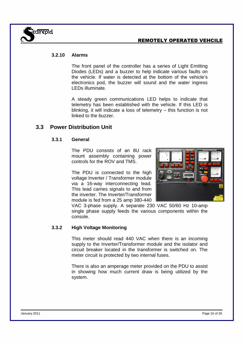
The PDU consists of an 8U rack mount assembly containing power controls for the ROV and TMS. The PDU is connected to the high voltage Inverter / Transformer module via a 16-way interconnecting lead. This lead carries signals to and from the inverter. The Inverter/Transformer module is fed from a 25 amp 380-440 VAC 3-phase supply. A separate 230 VAC 50/60 Hz 10-amp single phase supply feeds the various components within the console.
3.3.2 High Voltage Monitoring
This meter should read 440 VAC when there is an incoming supply to the Inverter/Transformer module and the isolator and circuit breaker located in the transformer is switched on. The meter circuit is protected by two internal fuses. There is also an amperage meter provided on the PDU to assist in showing how much current draw is being utilized by the system.

REMOTELY OPERATED VEHCILE
January 2011 Page 17 of 26
3.3.3 TMS Functions
TMS functionality is provided to the pilot through the PDU and the pilot’s hand controller. These features include the latch open/close, water sense alarm, compensation alarm, transformer high temperature, TMS light controls, and a tether line out meter. These functions are transmitted down through to the TMS through the telemetry boards.
3.3.4 Earth Fault Monitoring System
The earth fault detection system monitors the insulation between ground and both the isolated 3,000 VAC 3-phase supply and the 320 VDC supplies on the ROV and TMS.
• 3,000 V Line Insulation Monitor
The 3,000 V supply lines are continuously monitored even when the power is off, using an industry standard Bender module located on the rear panel of the PDU. User functions, such as test and reset, are accessible on the front of the PDU. The Bender unit monitors the neutral point of the 3,000 V transformer via a high voltage coupler located in the transformer module. This system has two alarms designed to inform the pilot that there potentially is a problem. The first alarm is set to 400K ohms and results in an audible alarm once the system reaches this level. The second alarm is set to 80K ohms and will automatically shut down power to the TMS and ROV if this level is reached, accompanied by an audible alarm.
• 320 VDC Line Insulation Monitor The ROV and TMS operate on a 320 VDC supply. The line insulation monitoring is provided by an industry standard Bender modlule fitted to the LIM/Capacitor Board located within the TOV and TMS electronics pods. The output of the Bender unit is fed into one of the analog channels of the telemetry system. This system has two alarms designed to inform the pilot that there potentially is a problem. The first alarm is set to 400K ohms and results in an audible alarm once the system reaches this level. The second alarm is set to 80K ohms and will automatically shut down power to the TMS and ROV if this level is reached, accompanied by an audible alarm.

REMOTELY OPERATED VEHCILE
January 2011 Page 18 of 26
• Test and Reset switches Remote test and reset switches are located on the front pannel of the PDU. Holding down the test button for 2-3 seconds will simulate an earth fault. It is standard practice to carry out these tests at regular intervals.
3.3.5 Alarms
The PDU offers several alarms and safety features to the Mohican ROV system. Through the PDU, alarms for earth fault detection, TMS water sense, transformer high temperature, and low compensators are provided to insure that the system is running properly. All of these alarms are accompanied by an audible tone to inform the personnel of the potential problem. The earth fault systems also incorporate a safety shutoff feature described in section 3.3.4.
3.4 High Voltage Transformer Units and Junction Box
The Inverter/Transformer Module is the power source for the ROV and TMS. The module requires 380-440 3-phase supply at 25 amps. The incoming supply is fed to a lockable isolation switch then to a 20 amp circuit breaker. The output of the circuit breaker is fed to the 15 KW inverter via a mains filter. The filter helps prevent any pulse width modulation (PWM) noise getting back into the mains supply. The inverter converts its input power into a 380-440V 3 phase 400 Hz output which is connected to the transformer. The output side of the transformer produces 3,000 VAC 3-phase at 400 Hz, which is then sent subsea. From the High Voltage Transformer, all communication and power wires are joined to the Deck Interconnect Cable via a Junction Box. This box is used to increase efficiency in the mobilization, demobilization and the diagnostic stages of all operations. This junction box incorporates a safety shut-off switch to automatically isolate the system when the door to the junction box is not secured properly.
3.5 Deck Interconnect Cable
The deck interconnect cable is utilized to connect the surface components with those subsea. This umbilical contains all of the power, signal conductors, and fiber elements used to control the TMS and ROV.

REMOTELY OPERATED VEHCILE
January 2011 Page 19 of 26
4. Tether Management System (TMS) 4.1 Sub-Atlantic Mohican TMS General
The (TMS) allows the ROV greater excursion distances at the working depth as opposed to a live boating system. Live boating is where the ROV is deployed over the side of the vessel and flown down to the required working depth. The TMS operations also enable the ROV to be used in more severe weather conditions than live boating as the effect of swell and currents acting on the tether are minimized. This fully electric TMS is made of corrosion resistant stainless steel. The system is designed as a telescopic frame which allows for expansion of various under-slung tooling skids to be fitted to the ROV. The system is surrounded with polypropylene sections around the vehicles entrance to prevent damage to the vehicle and tether as it leaves and re-enters the TMS. The TMS is powered using a 3,000 VAC 400 Hz power transmission system which is converted 300 VDC using a high frequency transformer on the TMS. A dedicated camera and lighting system allows the operator to monitor the status of the ROV and tether spooling as it leaves and re-enters the TMS. Video and telemetry are transmitted through a fiber optic multiplexer located in the electronics pod. The electrical junction boxes and slip ring are pressure compensated using 2 x 2700cc compensators providing a pressure of approximately 0.7 bar / 10 PSI above the surrounding environment.
4.2 Specification
• TMS Type: Side Entry Garage with winch and level wind mechanism.
• Drive System: 2200 W DC Electric Motor

REMOTELY OPERATED VEHCILE
January 2011 Page 20 of 26
• Tether Capacity: 820 feet (250 meters) of flying lead • Line Pull: 130 lbs (60 kg) • Tether Type: Thermo-plastic with Kevlar strain
members (Section 4.11.2)
4.3 TMS Weight / Dimensions
• Weight in air: 1,212 lbs (550 kg)
• Weight in water: 904 lbs (410 kg)
• Overall Length: 63 inches (1,600 mm)
• Overall height (standard): 64 inches (1,630 mm)
• Overall height (extended): 80 inches (2,025 mm)
• Overall width: 42 inches (1,075 mm)
• Safe Gross Load: 4,410 lbs (2,000 kg)
4.4 Frame The TMS frame consisting of three main structures, upper frame, lower frame, and the chassis are manufactured from 316L Stainless Steel to form a strong maintenance free structure. Cathodic anodes, fixed at various points, provide protection against corrosion. The upper and lower frames are telescopic allowing the height of the vehicle entry to be increased to accommodate vehicles with under-slung tooling skids. The position of the traction assembly is also adjustable to keep the tether in the correct position in relation to the vehicle when the TMS is extended.
4.5 Lifting Gimbal The Gimbal assembly is bolted to the upper frame and forms the lift point for the TMS. The Gimbal position is adjustable with five different positions to allow for any movement in center of gravity due to the positioning of equipment on the ROV. The Gimbal and bullet assembly are load tested in accordance with Sub-Atlantic’s test procedure which states that a load of 13,227 lbs (6,000 kg) is applied for 5 minutes.
4.6 Drive System The Mohican TMS is completely electrically operated and utilizes a unique system to drive the main tether drum and traction wheel using a

REMOTELY OPERATED VEHCILE
January 2011 Page 21 of 26
single electric motor while maintaining cable tension and accurate spooling. The oil filled, pressure compensated drive system consists of a drive motor, tether drum gearbox, and traction wheel gearbox. The motor is mounted directly onto the tether drum gearbox which drives the drum via a worm gear. The worm gear provides a natural brake for the drum when the motor power is removed. The drum gearbox and traction wheel gearbox are linked using a flexible drive assembly. The traction wheel gearbox is used to push tether out of the TMS as required by the ROV and to maintain tension on the drum preventing any incorrect spooling or bunching up of the tether.
4.7 ROV Latching Assembly The vehicle depressor unit utilizes a 24 VDC rotator/tilt unit to vertically restrain the vehicle in the TMS. When activated, a rubber lined bar is pressed down onto the buoyancy of the ROV clamping it into the TMS. The adjustable clamp bar assembly allows for differing heights in the ROV configurations and telescopic positions of the TMS frame.
4.8 Transformer / Junction Box The oil-filled transformer box houses the high voltage / high frequency transformer and also serves as the termination point for the main lift umbilical. The primary side of the transformer is supplied with 3,000 VAC 3-phase at 400 Hz via the main lift umbilical and provides the rest of the system with 320 VDC to power both the ROV and TMS. The transformer box is oil-filled and connected to two 2,700 cc pressure compensators, which maintain a positive internal pressure of 10 PCI, preventing water ingress. The transformer box also serves as the termination point for the slipring – which supplies data and power to the ROV. The slip ring is connected to the transformer box via a clear Tygon tube. This allows oil to pass through to the slip-ring and rotating junction box.

REMOTELY OPERATED VEHCILE
January 2011 Page 22 of 26
4.9 TMS Electronics Enclosure The electronics enclosure contains all the electronic circuit boards required to control the TMS functions which include lights, tilt unit, camera, and drive motor. The electronics pod is made from a hard anodized aluminum single atmosphere housing designed for underwater use. A number of underwater connectors connect the pod to the various external devices on the TMS.
4.10 TMS Sensors
The TMS system is designed with a camera and lighting system to assist the pilot when entering and exiting the TMS. The lighting can also assist with visual acquisition of the TMS subsea. 4.10.1 TMS Lights
A video camera is fitted to the TMS to monitor the tether drum and the ROV as it leaves and returns to the TMS. The video signal is transmitted to the surface controller via the fiber optic multiplexer.
4.10.2 TMS Camera
The TIMS is equipped with two 250 WATT 230 VDC lights connected to the electronics pod. The supplies to the lights are fused using 2-amp fast blow fuses located inside the electronics pod. This board is also used to switch the lights on and off. The ON/OFF switches for the lights are located on the front panel of the PDU. When the lights are switched off on the onboard relay isolate both positive and negative legs of the supply to the lights.
4.11 Tether
The Mohican ROV system utilizes two separate tethers to transfer the power and commands to the ROV and TMS. The Armored Umbilical is the primary connection between the surface and the TMS. Between the TMS and the ROV, the Flying Lead provides the power, communications, and fiber connections to control the vehicle.

REMOTELY OPERATED VEHCILE
January 2011 Page 23 of 26
4.11.1 Sample of the Armored Umbilical
4.11.2 Sample of the Flying Lead

REMOTELY OPERATED VEHCILE
January 2011 Page 24 of 26
5. Launch and Recovery System (LARS)
Equipment This equipment is an ROV launch and recovery system (LARS) with an integral winch, A Frame, and hydraulic power unit (HPU) based on a container type transport configuration (skid). It is self-contained, with the exception of electrical power input and water for the oil cooler. Specifications:
LARS Skid Length 16.4 ft (5,000 mm)
Width 9.47 ft (2,890 mm)
Height 11.8 ft (3,620 mm)
Weight 14.5 tonnes
Lifting Options 4 point using 4 slings adjusted in length for balance or Fork Lift Pockets
Hydraulic Power
Prime Mover 30 kw safe area Electric Motor 380 – 460 VAC 3-Phase 50/60 Hz Motor Speed 1500 – 1760 rpm
Starter 30 kw Safe area star/delta starter, isolator, and control fuses
Hydraulic Pump Cassapa KP 38 D
Flow: 17.6 gpm (66.8 lpm)
Pressure: 260 (300 peak)
5.1 ROV Lift Winch
The ROV winch is driven by a Poclain MS 50 high torque, slow speed multi disc brake direct drive to a winch drum. Maximum pressure of 450 bar and displacement of 6,011 cc 5.1.1 Ratings and Capacity
• Line Pull 4,000 kg at first layer • Line speed 30 m/min at first layer

REMOTELY OPERATED VEHCILE
January 2011 Page 25 of 26
5.2 A-Frame
The A-Frame allows for a safe method of lifting the ROV and TMS over the water during launch and recovery. This system is hydraulically controlled with “fail safe” braking to insure that the system remains within the command and control of the operator.
• Max Out Reach 11 ft (3.4 m) including sheave wheel • Maximum S.W.L 11,000 lbs (5,000 kg) line pull
5.3 Umbilical Termination Box
The Mohican LARS is designed with a termination box to connect the deck lead from the command/control van to the slip ring and subsea electronics.
5.4 Slip Ring Installed in the Mohican LARS is a Focal model 176 slip ring assembly. This system is designed to carry up to 5,000 VAC and withstand 20 amps per pass. This slip ring is designed with 8 high voltage passes, 3 low voltage passes, and 3 optical passes to control the ROV and TMS system.
5.5 Schematic Drawing

REMOTELY OPERATED VEHCILE
January 2011 Page 26 of 26
6. Control and Work Van
Accompanying the Mohican ROV system is a Control Van. One end of the container will house the pilot’s and observer’s control station while the other end of the container will house the surface transformer and workshop. Suitable heading and air conditioning are provided to maintain a comfortable working environment. Lighting and seating is arranged to provide an ergonomic workplace for personnel.
6.1 Control and Work Van Specifications: 6.1.1 Purpose built Crimped Plate Steel Container:
Height: 8.5 ft (2.6 m) Width: 8.0 ft (2.4 m) Length: 22.2 ft (6.8 m) Weight: 22,000 lb (10,000 kg)
6.1.2 Electrical:
Input: 440 VAC 3 phase 50 / 60 Hz Available: Multiple 220 VAC and 110 VAC Outlets Lighting: 48” x 2 tube Fluorescent lights
Red incandescent light (with dimmer) Emergency Lighting
6.1.3 Features:
Industry recognized lifting pad eyes
Smoke Detection System
Forklift pockets First Aid Kits Emergency Lighting Emergency Eye Wash Station
6.1.4 Pilot’s and Observer’s Station:
1 x 40” Sony Monitor 4 x 15” JVC Monitors 2 x 7” Monitors 2 x DVD Recorders 1 x Blackbox recorder
1 x 19” 4U Rackmount PC