sealite sl-70 3 nautical mile solar marine light · pdf filespecifications•* sl-70 light...
TRANSCRIPT

Version 4.3
SL-702–3NM+ Solar Marine LanternInstallation & Service Manual

SL-702–3NM+ Solar Marine Lantern
Lens and base moulded from UV-stabilised
LEXAN® polycarbonate
Large industry standard 200mm bolt
pattern for ease of installation
Dual internal high-performance solar
modules
Single LED Optic
Internal user-replaceable battery in sealed
compartment

Latest products and information available at www.sealite.com3
SL-70 2–3NM+ Solar Marine Lantern
Table of Contents
Introduction ....................................................................................................... Page 4
Operating Principle .......................................................................................... Page 4
Technology ........................................................................................................ Page 4
SL-70 Model ......................................................................................................Page 5
Installation ......................................................................................................... Page 6
Selecting an Intensity/Power Setting.............................................................. Page 7
Selecting a Flash Code .................................................................................... Page 7
Flash Codes ...................................................................................................... Page 8
Optional IR Remote Control .......................................................................... Page 13
Sealite IR Controller / Universal Remote Compatibility .............................. Page 13
IR Controller Functions .................................................................................. Page 14 Test Mode / Configure ................................................................................. Page 14 Normal Operation........................................................................................ Page 14 Read ...........................................................................................................Page 14 Flash Code.................................................................................................. Page 15 Flash Code Numbers .................................................................................. Page 15 Intensity.......................................................................................................Page 15 Battery Status ............................................................................................. Page 15 Lux ..............................................................................................................Page 16 Error / Acknowledge Indication ................................................................... Page 17 Configuration Settings................................................................................. Page 17 Hibernation Mode (Advanced Users) .......................................................... Page 18 Storage Mode (Advanced Users)................................................................ Page 20
Optional GPS Synchronisation ..................................................................... Page 21
Optional AvMesh® Monitoring & Control System ....................................... Page 22
Optional RF Synchronisation ........................................................................ Page 22
Maintenance and Servicing ........................................................................... Page 23
Trouble Shooting ............................................................................................ Page 24
Sealite LED Light Warranty ........................................................................... Page 26
Version No. Description Date Approved3.3 Re launch Catalogue July 2009 K. Paton3.4 Logo and Warranty Update July 2010 K. Paton3.5 Update: Spec Table May 2012 J. Dore3.6 Update: Photometrics August 2012 J. Dore4.0 Single LED May 2014 D. Tomaszewicz4.1 Spec table update February 2015 J. Dore4.2 Update: Contact details January 2016 J. Dore4.3 IR Controller flash codes February 2016 J. Dore
Latest products and information available at www.sealite.com4
SL-70 2–3NM+ Solar Marine Lantern
IntroductionCongratulations! By choosing to purchase a Sealite lantern you have become the owner of one of the most advanced LED marine lanterns in the world.Sealite Pty Ltd has been manufacturing lanterns for over 25 years, and particular care has been taken to ensure your lantern gives years of service.As a commitment to producing the highest quality products for our customers, Sealite has been independently certified as complying with the requirements of ISO9001:2008 quality management system.Sealite lanterns comply with requirements of the US Coast Guard in 33 CFR part 66 for Private Aids To Navigation.By taking a few moments to browse through this booklet, you will become familiar with the versatility of your lantern, and be able to maximise its operating function.
Operating PrincipleThe solar module of the lantern converts sunlight to an electrical current that is used to charge the battery. The battery provides power to operate the lantern at night. The flasher unit has very low current requirements. A microprocessor drives an ultra bright LED through a through a DC/DC converter, which enables the LED’s to operate within the manufacturer’s specifications. The battery is protected from over-charging within the circuit to ensure maximum battery life. On darkness, the microprocessor will initiate a program check and after approximately 1 minute begin flashing to the set code
TechnologySealite is the world’s fastest growing manufacturer of marine aids to navigation. We employ leading mechanical, optical, hardware & software engineers to create innovative products to service the needs of our customers worldwide, and offer the widest range of solar-powered LED lanterns in the marketplace. ElectronicsSealite employs leading in-house electronic engineers in the design and development of software and related circuitry. All individual electronic components are sourced directly by Sealite procurement staff ensuring that only the highest quality components are used in our products.
LED TechnologyAll marine lanterns use the latest advancements in LED (Light Emitting Diode) technology as a light source. The major advantage of LED’s over traditional light sources is well established in that they typically have an operational life in excess of 100,000 hours, resulting in substantial savings to maintenance and servicing costs.
Precision Construction Commitment to investing in the design and construction of injection-moulded parts including optic lenses, light bases and a range of other components ensures that all Sealite products are of a consistent & superior quality.
Optical PerformanceSealite manufactures a range of marine LED lenses moulded from multi-cavity dies. The company has superior in-house lens manufacturing capabilities to support outstanding optical performance.
Award-winning, Patented Technology Several United States and Australian patent registrations are held on Sealite’s range of innovative designs, with other regional patents pending in Canada, United Kingdom and Europe.
SL-70 2–3NM+ Solar Marine Lantern
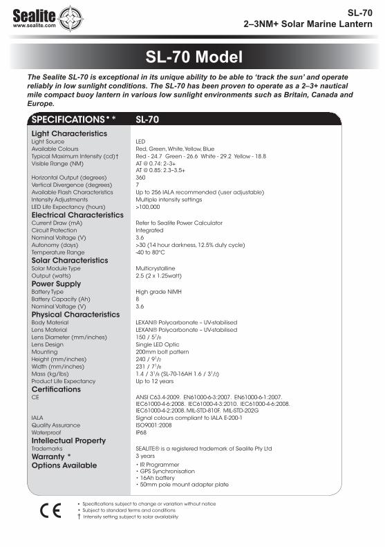
SL-70 ModelThe Sealite SL-70 is exceptional in its unique ability to be able to ‘track the sun’ and operate reliably in low sunlight conditions. The SL-70 has been proven to operate as a 2–3+ nautical mile compact buoy lantern in various low sunlight environments such as Britain, Canada and Europe.
• Specifications subject to change or variation without notice
* Subject to standard terms and conditions† Intensity setting subject to solar availability
SPECIFICATIONS•* SL-70Light CharacteristicsLight Source LEDAvailable Colours Red, Green, White, Yellow, BlueTypical Maximum Intensity (cd)† Red - 24.7 Green - 26.6 White - 29.2 Yellow - 18.8 Visible Range (NM) AT @ 0.74: 2–3+
AT @ 0.85: 2.3–3.5+Horizontal Output (degrees) 360Vertical Divergence (degrees) 7Available Flash Characteristics Up to 256 IALA recommended (user adjustable)Intensity Adjustments Multiple intensity settingsLED Life Expectancy (hours) >100,000
Electrical CharacteristicsCurrent Draw (mA) Refer to Sealite Power CalculatorCircuit Protection IntegratedNominal Voltage (V) 3.6Autonomy (days) >30 (14 hour darkness, 12.5% duty cycle)Temperature Range -40 to 80°C
Solar CharacteristicsSolar Module Type MulticrystallineOutput (watts) 2.5 (2 x 1.25watt)
Power SupplyBattery Type High grade NiMH Battery Capacity (Ah) 8Nominal Voltage (V) 3.6
Physical CharacteristicsBody Material LEXAN® Polycarbonate – UV-stabilisedLens Material LEXAN® Polycarbonate – UV-stabilisedLens Diameter (mm/inches) 150 / 57/8
Lens Design Single LED OpticMounting 200mm bolt patternHeight (mm/inches) 240 / 91/2
Width (mm/inches) 231 / 71/8
Mass (kg/lbs) 1.4 / 31/8 (SL-70-16AH 1.6 / 31/2) Product Life Expectancy Up to 12 years
CertificationsCE ANSI C63.4-2009. EN61000-6-3:2007. EN61000-6-1:2007.
IEC61000-4-6:2008. IEC61000-4-3:2010. IEC61000-4-6:2008. IEC61000-4-2:2008. MIL-STD-810F. MIL-STD-202G
IALA Signal colours compliant to IALA E-200-1Quality Assurance ISO9001:2008Waterproof IP68
Intellectual PropertyTrademarks SEALITE® is a registered trademark of Sealite Pty Ltd
Warranty * 3 years
Options Available • IR Programmer• GPS Synchronisation• 16Ah battery• 50mm pole mount adapter plate

Latest products and information available at www.sealite.com6
SL-70 2–3NM+ Solar Marine Lantern
Charging the BatteryNew lanterns should be left in the sun for 1-2 days to ensure battery is charged before placing in service. Please note, lantern will re-charge even when toggle switch os turned to ‘OFF’ position.
Preferred Installation LocationFor best lantern performance, ensure solar modules are not covered and are in clear view of the sky with no shadows.
Lantern OperationLantern is activated by ON/OFF Switch. Intensity and flash settings need to be set prior to activation. 1. Remove the marked flash adjustment bung from the base of the lantern and set internal toggle
switch to ‘ON’.2. The power and range settings of the lantern are adjusted by setting the DIP switches inside the
lantern. Your lantern is normally set to maximum range (see ‘Selecting an Intensity/Power Setting’ section of this manual).
3. Set rotary switches to the required flash code (see ‘Selecting a Flash Code’ section of this manual).
4. Replace flash adjustment bung. 5. A sealed vent on the base allows air transfer without moisture intake, and should not be disturbed.6. To test place dark cover (towel or jacket) on top of lantern to activate sensor, lantern will come on.7. Ensure that the unit is bolted to an even, flat surface.
45
6 7 8 9 ABC
D
EF0123
45
6 7 8 9 ABC
D
EF0123
A
B
1
2
ON
ONRotary Switch B
Rotary Switch A
Intensity Setting
FLAS
H
ADJUST
ME
NT
SEA
LE
D
VE
NT
ON / OFF Switch
UserReplaceable
Battery
LanternBase
Installation

Latest products and information available at www.sealite.com7
SL-70 2–3NM+ Solar Marine Lantern
Intensity/power settings on Sealite lanterns operate via DIP switches, located near the rotary switches on the flasher unit. The intensity/power settings may be used to reduce the power consumption and intensity of the lantern. Setting the lantern to 25% intensity will reduce the power consumption to 25% of the normal 100% setting and the range by 20% - 40% depending on the maximum intensity. Refer to Sealite power calculator to confirm reduced range.. This setting may be used to adjust the current draw of the light to local sunlight conditions. The following diagrams indicate intensity/power settings:-
Power Consumption Calculator
If the number of Full Sunlight hours is less than 2.5-3.0 hours, please consider reducing the intensity (Power) or reducing the Duty Cycle.
All lanterns have 2 rotary switches marked A and B on the flasher unit. Turning the small arrows to the appropriate number or letter will set the code (see ‘Flash Codes’ section, of this manual). The unit may take up to one minute to activate a new flash code. A comprehensive list of available flash codes is listed on pages in the ‘Flash Codes’ section of this manual.Example:
100%
1 2
ON
75%
1 2
ON
50%
1 2
ON
25%
1 2
ONIntensity Setting
PowermA / hour
100% 85mA75% 64mA50% 43mA25% 22mA
45
6 7 8 9 ABC
DEF0123
45
6 7 8 9 ABC
D
EF0123 A
BSWITCH FLASH CODE ON OFFA BA 0 FL 3 S 0.3 2.7
Night Hours(use 13.7 if unknown)
PowermA/hour
Duty Cycle(e.g. 20% = 0.2)
Total power used per night
(mA)
X X =Total power
used per night(mAh)
Solar Panel Charge (mA)
Number of full sunlight hours required to break even
(the amount of time it will take for the solar to replace what the light took out overnight)
/ 279 =
Selecting an Intensity/Power Setting
Selecting a Flash Code - Rotary Switches A & B

Latest products and information available at www.sealite.com8
SL-70 2–3NM+ Solar Marine Lantern
Flash CodesThe Sealite SL-70 may be set to any of 256 IALA recommended flash settings which are user-adjustable onsite without the need for external devices.
SEALITE® code reference is listed by number of flashes
For the latest version of this document visit www.sealite.com, or email [email protected]
SymbolsFL Flash followed by number Eg. FL 1 S, one flash every secondF FixedQ Quick flashVQ Very quick flashOC Occulting; greater period on than off ISO Isophase; equal period on and offLFL Long flash longMO Morse code ( ) contains letter
For example, VQ (6) + LFL 10 S means 6 very quick flashes followed by a long flash, during a 10-second interval.The amount of power your lantern draws through the night depends on the duty cycle, i.e. the amount of time on as a proportion to the timing cycle. For example, 0.5 seconds on and 4.5 seconds off equals a 10% duty cycle. It is best to operate at the lowest duty cycle appropriate to the actual needs of the application.
Recommended Rhythm for Flashing Light - IALA Regions A and B
MARK DESCRIPTION RHYTHMPort Hand & Starboard Marks: Any, other than Composite Group Flashing (2+1)
Preferred Channel Starboard: Composite Group Flashing (2+1)
Preferred Channel Port: Composite Group Flashing (2+1)
North Cardinal Mark: Very quick or quick
East Cardinal Mark: Very quick (3) every 5 seconds or quick (3) every 10 seconds
South Cardinal Mark: Very quick (6) + long flash every 10 seconds or quick (6) + long flash every 15 seconds
West Cardinal Mark: Very quick (9) every 10 seconds or quick (9) every 15 seconds
Isolated Danger Mark: Group flashing (2)
Safe Water Mark: Isophase, occulting, one long flash every 10 seconds or Morse Code “A”
Special Marks: Any, other than those described for Cardinal, Isolated Danger or Safe Water Marks

Latest products and information available at www.sealite.com9
SWITCHIR
Controller FLASH CODE ON OFFA B0 0 000 F (Steady light)D 3 211 VQ 0.5 S 0.2 0.3E 3 227 VQ 0.6 S 0.2 0.4F 3 243 VQ 0.6 S 0.3 0.37 3 115 Q 1 S 0.2 0.88 3 131 Q 1 S 0.3 0.79 3 147 Q 1 S 0.4 0.6A 3 163 Q 1 S 0.5 0.58 4 132 Q 1 S 0.8 0.2B 3 179 Q 1.2 S 0.3 0.99 4 148 Q 1.2 S 0.5 0.7C 3 195 Q 1.2 S 0.6 0.6F 4 244 FL 1.5 S 0.2 1.31 0 16 FL 1.5 S 0.3 1.20 5 5 FL 1.5 S 0.4 1.10 4 4 FL 1.5 S 0.5 1.02 0 32 FL 2 S 0.2 1.83 0 48 FL 2 S 0.3 1.74 0 64 FL 2 S 0.4 1.65 0 80 FL 2 S 0.5 1.56 0 96 FL 2 S 0.7 1.37 0 112 FL 2 S 0.8 1.21 2 18 ISO 2 S 1.0 1.08 0 128 FL 2.5 S 0.3 2.29 0 144 FL 2.5 S 0.5 2.0D 6 214 FL 2.5 S 1.0 1.51 5 21 FL 3 S 0.2 2.8A 0 160 FL 3 S 0.3 2.72 5 37 FL 3 S 0.4 2.6B 0 176 FL 3 S 0.5 2.53 5 53 FL 3 S 0.6 2.4C 0 192 FL 3 S 0.7 2.3D 0 208 FL 3 S 1.0 2.02 2 34 ISO 3 S 1.5 1.55 4 84 OC 3 S 2.0 1.0E 2 226 OC 3 S 2.5 0.54 6 70 OC 3.5 S 2.5 1.04 5 69 FL 4 S 0.2 3.85 5 85 FL 4 S 0.3 3.7E 0 224 FL 4 S 0.4 3.6F 0 240 FL 4 S 0.5 3.56 5 101 FL 4 S 0.6 3.40 1 1 FL 4 S 0.8 3.21 1 17 FL 4 S 1.0 3.02 1 33 FL 4 S 1.5 2.53 2 50 ISO 4 S 2.0 2.03 6 54 OC 4 S 2.5 1.5F 2 242 OC 4 S 3.0 1.03 1 49 FL 4.3 S 1.3 3.08 5 133 FL 5 S 0.2 4.84 1 65 FL 5 S 0.3 4.75 1 81 FL 5 S 0.5 4.59 5 149 FL 5 S 0.9 4.16 1 97 FL 5 S 1.0 4.0
SWITCHIR
Controller FLASH CODE ON OFFA B7 1 113 FL 5 S 1.5 3.54 2 66 ISO 5 S 2.5 2.58 2 130 LFL 5 S 2.0 3.00 3 3 OC 5 S 3.0 2.01 3 19 OC 5 S 4.0 1.02 3 35 OC 5 S 4.5 0.5C 6 198 FL 6 S 0.2 5.8B 5 181 FL 6 S 0.3 5.7C 5 197 FL 6 S 0.4 5.68 1 129 FL 6 S 0.5 5.59 1 145 FL 6 S 0.6 5.4A 1 161 FL 6 S 1.0 5.07 5 117 FL 6 S 1.2 4.8B 1 177 FL 6 S 1.5 4.55 2 82 ISO 6 S 3.0 3.09 2 146 LFL 6 S 2.0 4.06 4 100 OC 6 S 4.0 2.03 3 51 OC 6 S 4.5 1.54 3 67 OC 6 S 5.0 1.0A 4 164 FL 7 S 1.0 6.09 6 150 FL 7 S 2.0 5.05 6 86 OC 7 S 4.5 2.5D 5 213 FL 7.5 S 0.5 7.0C 1 193 FL 7.5 S 0.8 6.7E 5 229 FL 8 S 0.5 7.5B 4 180 FL 8 S 1.0 7.06 2 98 ISO 8 S 4.0 4.0A 2 162 LFL 8 S 2.0 6.06 6 102 OC 8 S 5.0 3.0B 2 178 LFL 8 S 3.0 5.0F 5 245 FL 9 S 0.9 8.1C 4 196 FL 9 S 1.0 8.07 6 118 OC 9 S 6.0 3.00 6 6 FL 10 S 0.2 9.81 6 22 FL 10 S 0.3 9.7D 1 209 FL 10 S 0.5 9.52 6 38 FL 10 S 0.8 9.2E 1 225 FL 10 S 1.0 9.01 4 20 FL 10 S 1.5 8.5C 2 194 LFL 10 S 2.0 8.0D 2 210 LFL 10 S 3.0 7.07 2 114 ISO 10 S 5.0 5.02 4 36 LFL 10 S 4.0 6.08 6 134 OC 10 S 6.0 4.05 3 83 OC 10 S 7.0 3.06 3 99 OC 10 S 7.5 2.5F 1 241 FL 12 S 1.2 10.8D 4 212 FL 12 S 2.5 9.53 4 52 LFL 12 S 2.0 10.00 2 2 FL 15 S 1.0 14.04 4 68 LFL 15 S 4.0 11.07 4 116 OC 15 S 10 5.0A 6 166 LFL 20 S 2.0 18.0E 4 228 FL 26 S 1.0 25.0

Latest products and information available at www.sealite.com10
SL-70 2–3NM+ Solar Marine Lantern
SWITCHIR
Controller FLASH CODE ON OFF ON OFFA B0 A 10 FL (2) 4 S 0.5 1.0 0.5 2.0E B 235 VQ (2) 4 S 0.2 1.0 0.2 2.61 A 26 FL (2) 4.5 S 0.3 1.0 0.3 2.92 A 42 FL (2) 4.5 S 0.4 1.0 0.4 2.73 A 58 FL (2) 4.5 S 0.5 1.0 0.5 2.5F 9 249 FL (2) 5 S 0.2 0.8 0.2 3.82 C 44 FL (2) 5 S 0.2 1.2 0.2 3.44 A 74 FL (2) 5 S 0.4 0.6 0.4 3.60 7 7 FL (2) 5 S 0.5 1.0 0.5 3.01 7 23 FL (2) 5 S 1.0 1.0 1.0 2.09 B 155 Q (2) 5 S 0.3 0.7 0.3 3.72 9 41 Q (2) 5 S 0.5 0.5 0.5 3.55 A 90 FL (2) 5.5 S 0.4 1.4 0.4 3.37 8 120 FL (2) 6 S 0.3 0.6 1.0 4.1A A 170 FL (2) 6 S 0.3 0.9 0.3 4.56 A 106 FL (2) 6 S 0.3 1.0 0.3 4.47 A 122 FL (2) 6 S 0.4 1.0 0.4 4.29 9 153 FL (2) 6 S 0.5 1.0 0.5 4.02 8 40 FL (2) 6 S 0.8 1.2 0.8 3.23 7 55 FL (2) 6 S 1.0 1.0 1.0 3.03 9 57 Q (2) 6 S 0.3 0.7 0.3 4.7A 9 169 FL (2) 7 S 1.0 1.0 1.0 4.07 B 123 FL (2) 8 S 0.4 0.6 2.0 5.08 A 138 FL (2) 8 S 0.4 1.0 0.4 6.24 7 71 FL (2) 8 S 0.5 1.0 0.5 6.08 8 136 FL (2) 8 S 0.8 1.2 2.4 3.65 7 87 FL (2) 8 S 1.0 1.0 1.0 5.04 C 76 OC (2) 8 S 3.0 2.0 1.0 2.05 C 92 OC (2) 8 S 5.0 1.0 1.0 1.0F B 251 VQ (2) 8 S 0.2 1.0 0.2 6.69 A 154 FL (2) 10 S 0.4 1.6 0.4 7.66 7 103 FL (2) 10 S 0.5 1.0 0.5 8.07 7 119 FL (2) 10 S 0.5 1.5 0.5 7.56 9 105 FL (2) 10 S 0.5 2.0 0.5 7.08 7 135 FL (2) 10 S 0.8 1.2 0.8 7.2B 9 185 FL (2) 10 S 1.0 1.0 1.0 7.09 7 151 FL (2) 10 S 1.0 1.5 1.0 6.54 9 73 Q (2) 10 S 0.6 0.4 0.6 8.4B A 186 FL (2) 12 S 0.4 1.0 0.4 10.2C 9 201 FL (2) 12 S 0.5 1.0 0.5 10.0D 9 217 FL (2) 12 S 1.5 2.0 1.5 7.0A 8 168 FL (2) 15 S 0.5 1.5 2.0 11.0A 7 167 FL (2) 15 S 1.0 2.0 1.0 11.08 B 139 Q (2) 15 S 0.2 0.8 0.2 13.8C A 202 FL (2) 20 S 1.0 3.0 1.0 15.0D A 218 FL (2) 25 S 1.0 1.0 1.0 22.0
SWITCHIR
Controller FLASH CODE ON OFF ON OFF ON OFFA B7 9 121 Q (3) 5 S 0.5 0.5 0.5 0.5 0.5 2.55 9 89 VQ (3) 5 S 0.2 0.3 0.2 0.3 0.2 3.80 C 12 VQ (3) 5 S 0.3 0.2 0.3 0.2 0.3 3.7E 9 233 VQ (3) 5 S 0.3 0.3 0.3 0.3 0.3 3.53 C 60 FL (3) 6 S 0.5 1.0 0.5 1.0 0.5 2.52 B 43 FL (2+1) 6 S 0.3 0.4 0.3 1.2 0.3 3.5

Latest products and information available at www.sealite.com11
SWITCHIR
Controller FLASH CODE ON OFF ON OFF ON OFFA BA B 171 Q (3) 6 S 0.3 0.7 0.3 0.7 0.3 3.7F A 250 FL (3) 8 S 0.5 1.0 0.5 1.0 0.5 4.50 B 11 FL (3) 9 S 0.3 1.0 0.3 1.0 0.3 6.1B 7 183 FL (3) 9 S 0.8 1.2 0.8 1.2 0.8 4.2B 8 184 FL (3) 10 S 0.3 0.7 0.3 0.7 0.9 7.1C 8 200 FL (3) 10 S 0.4 0.6 0.4 0.6 1.2 6.8C B 203 FL (3) 10 S 0.5 0.5 0.5 0.5 0.5 7.5C 7 199 FL (3) 10 S 0.5 1.5 0.5 1.5 0.5 5.5D B 219 FL (3) 10 S 0.6 0.6 0.6 0.6 0.6 7.0D 7 215 FL (3) 10 S 1.0 1.0 1.0 1.0 1.0 5.03 8 56 FL (2+1) 10 S 0.5 0.7 0.5 2.1 0.5 5.78 9 137 OC (3) 10 S 5.0 1.0 1.0 1.0 1.0 1.0B B 187 Q (3) 10 S 0.3 0.7 0.3 0.7 0.3 7.7D 8 216 FL (2 + 1) 10 S 0.5 0.5 0.5 0.5 1.5 6.51 B 27 FL (3) 12 S 0.5 1.5 0.5 1.5 0.5 7.5E A 234 FL (3) 12 S 0.5 2.0 0.5 2.0 0.5 6.5E 7 231 FL (3) 12 S 0.8 1.2 0.8 1.2 0.8 7.2B 6 182 FL (3) 12 S 1.0 1.0 1.0 3.0 1.0 5.04 8 72 FL (2+1) 12 S 0.8 1.2 0.8 2.4 0.8 6.05 8 88 FL (2+1) 12 S 1.0 1.0 1.0 4.0 1.0 4.01 8 24 FL (2+1) 13.5 S 1.0 1.0 1.0 4.0 1.0 5.5F 7 247 FL (3) 15 S 0.3 1.7 0.3 1.7 0.3 10.79 D 157 FL (3) 15 S 0.4 1.0 0.4 1.0 0.4 11.80 8 8 FL (3) 15 S 0.5 1.5 0.5 1.5 0.5 10.5F 8 248 FL (2+1) 15 S 0.6 0.3 0.6 0.3 1.4 11.80 9 9 FL (2+1) 15 S 0.7 0.5 0.7 0.5 1.9 10.71 9 25 FL (2+1) 15 S 0.7 0.7 0.7 0.7 2.1 10.16 8 104 FL (2+1) 15 S 1.0 2.0 1.0 5.0 1.0 5.01 C 28 VQ (3) 15 S 0.1 0.5 0.1 0.5 0.1 13.74 B 75 FL (3) 20 S 0.5 3.0 0.5 3.0 0.5 12.53 B 59 FL (3) 20 S 0.5 1.5 0.5 1.5 0.5 15.55 B 91 FL (3) 20 S 0.8 1.2 0.8 1.2 0.8 15.26 B 107 FL (3) 20 S 1.0 1.0 1.0 1.0 1.0 15.0
SWITCHIR
Controller FLASH CODE ON OFF ON OFF ON OFF ON OFFA BB F 191 VQ (4) 4 S 0.3 0.3 0.3 0.3 0.3 0.3 0.3 2.3B D 189 Q (4) 6 S 0.3 0.7 0.3 0.7 0.3 0.7 0.3 2.78 D 141 Q (4) 6 S 0.4 0.6 0.4 0.6 0.4 0.6 0.4 2.61 D 29 FL (4) 10 S 0.5 1.0 0.5 1.0 0.5 1.0 0.5 5.02 D 45 FL (4) 10 S 0.8 1.2 0.8 1.2 0.8 1.2 0.8 3.2F E 254 Q (4) 10 S 0.3 0.7 0.3 0.7 0.3 0.7 0.3 6.7B E 190 FL (4) 12 S 0.3 1.7 0.3 1.7 0.3 1.7 0.3 5.74 F 79 FL (4) 12 S 0.5 0.5 0.5 0.5 0.5 0.5 0.5 8.5C E 206 FL (4) 12 S 0.5 1.5 0.5 1.5 0.5 1.5 0.5 5.53 D 61 FL (4) 12 S 0.8 1.2 0.8 1.2 0.8 1.2 0.8 5.2A D 173 Q (4) 12 S 0.3 0.7 0.3 0.7 0.3 0.7 0.3 8.74 D 77 FL (4) 15 S 0.5 1.5 0.5 1.5 0.5 1.5 0.5 8.58 E 142 FL (4) 15 S 1.0 1.0 1.0 1.0 1.0 1.0 1.0 8.07 D 125 FL (4) 15 S 1.5 0.5 0.5 0.5 0.5 0.5 0.5 10.5D E 222 FL (4) 16 S 0.5 1.5 0.5 1.5 0.5 1.5 0.5 9.5C D 205 FL (4) 20 S 0.3 3.0 0.3 3.0 0.3 3.0 0.3 9.85 D 93 FL (4) 20 S 0.5 1.5 0.5 1.5 0.5 1.5 0.5 13.50 D 13 FL (4) 20 S 0.5 1.5 0.5 1.5 0.5 4.5 0.5 10.53 F 63 FL (4) 20 S 1.5 1.5 1.5 1.5 1.5 1.5 1.5 9.50 F 15 Q (4) 20 S 0.5 0.5 0.5 0.5 0.5 0.5 0.5 16.5E E 238 Q (4) 28 S 0.5 0.5 0.5 0.5 0.5 0.5 0.5 24.56 F 111 FL (4) 30 S 0.5 0.5 0.5 0.5 0.5 0.5 0.5 26.5

Latest products and information available at www.sealite.com12
SL-70 2–3NM+ Solar Marine Lantern
SWITCHIR
Controller FLASH CODE ON OFF ON OFF ON OFF ON OFF ON OFF ON OFF ON OFF ON OFF ON OFFA B4 E 78 VQ (9) 10 S 0.2 0.3 0.2 0.3 0.2 0.3 0.2 0.3 0.2 0.3 0.2 0.3 0.2 0.3 0.2 0.3 0.2 5.85 E 94 VQ (9) 10 S 0.3 0.3 0.3 0.3 0.3 0.3 0.3 0.3 0.3 0.3 0.3 0.3 0.3 0.3 0.3 0.3 0.3 4.91 F 31 Q (9) 15 S 0.2 0.8 0.2 0.8 0.2 0.8 0.2 0.8 0.2 0.8 0.2 0.8 0.2 0.8 0.2 0.8 0.2 6.80 E 14 Q (9) 15 S 0.3 0.7 0.3 0.7 0.3 0.7 0.3 0.7 0.3 0.7 0.3 0.7 0.3 0.7 0.3 0.7 0.3 6.71 E 30 Q (9) 15 S 0.6 0.6 0.6 0.6 0.6 0.6 0.6 0.6 0.6 0.6 0.6 0.6 0.6 0.6 0.6 0.6 0.6 4.8
SWITCHIR
Controller FLASH CODE ON OFF ON OFF ON OFF ON OFFA BMORSE CODE ( ) INDICATES LETTER7 8 120 MO (A) 6 S 0.3 0.6 1.0 4.17 B 123 MO (A) 8 S 0.4 0.6 2.0 5.08 8 136 MO (A) 8 S 0.8 1.2 2.4 3.6B 8 184 MO (U) 10 S 0.3 0.7 0.3 0.7 0.9 7.1C 8 200 MO (U) 10 S 0.4 0.6 0.4 0.6 1.2 6.8D 8 216 MO (U) 10 S 0.5 0.5 0.5 0.5 1.5 6.59 8 152 MO (A) 10 S 0.5 0.5 1.5 7.58 9 137 MO (D) 10 S 5.0 1.0 1.0 1.0 1.0 1.0A 8 168 MO (A) 15 S 0.5 1.5 2.0 11.0F 8 248 MO (U) 15 S 0.6 0.3 0.6 0.3 1.4 11.80 9 9 MO (U) 15 S 0.7 0.5 0.7 0.5 1.9 10.71 9 25 MO (U) 15 S 0.7 0.7 0.7 0.7 2.1 10.17 D 125 MO (B) 15 S 1.5 0.5 0.5 0.5 0.5 0.5 0.5 10.5
SWITCHIR
Controller FLASH CODE ON OFF ON OFF ON OFF ON OFF ON OFFA BD D 221 Q (5) 7 S 0.3 0.7 0.3 0.7 0.3 0.7 0.3 0.7 0.3 2.7E D 237 Q (5) 10 S 0.3 0.7 0.3 0.7 0.3 0.7 0.3 0.7 0.3 5.7E 8 232 FL (5) 12 S 0.5 1.5 0.5 1.5 0.5 1.5 0.5 1.5 0.5 3.55 F 95 FL (5) 20 S 0.5 0.5 0.5 0.5 0.5 0.5 0.5 0.5 0.5 15.59 F 159 FL (5) 20 S 0.8 1.2 0.8 1.2 0.8 1.2 0.8 1.2 0.8 11.29 E 158 FL (5) 20 S 1.0 1.0 1.0 1.0 1.0 1.0 1.0 1.0 1.0 11.0
SWITCHIR
Controller FLASH CODE ON OFF ON OFF ON OFF ON OFF ON OFF ON OFFA BF D 253 Q (6) 10 S 0.3 0.7 0.3 0.7 0.3 0.7 0.3 0.7 0.3 0.7 0.3 4.7A F 175 FL (6) 15 S 0.3 0.7 0.3 0.7 0.3 0.7 0.3 0.7 0.3 0.7 0.3 9.77 F 127 FL (6) 15 S 0.5 1.0 0.5 1.0 0.5 1.0 0.5 1.0 0.5 1.0 0.5 7.0
SWITCHIR
Controller FLASH CODE ON OFF ON OFF ON OFF ON OFF ON OFF ON OFF ON OFFA B6 E 110 VQ (6) + LFL 10 S 0.2 0.3 0.2 0.3 0.2 0.3 0.2 0.3 0.2 0.3 0.2 0.3 2.0 5.07 E 126 VQ (6) + LFL 10 S 0.3 0.3 0.3 0.3 0.3 0.3 0.3 0.3 0.3 0.3 0.3 0.3 2.0 4.42 F 47 Q (6) + LFL 15 S 0.2 0.8 0.2 0.8 0.2 0.8 0.2 0.8 0.2 0.8 0.2 0.8 2.0 7.02 E 46 Q (6) + LFL 15 S 0.3 0.7 0.3 0.7 0.3 0.7 0.3 0.7 0.3 0.7 0.3 0.7 2.0 7.03 E 62 Q (6) + LFL 15 S 0.6 0.6 0.6 0.6 0.6 0.6 0.6 0.6 0.6 0.6 0.6 0.6 2.0 5.88 F 143 VQ (6) + LFL 15 S 0.3 0.3 0.3 0.3 0.3 0.3 0.3 0.3 0.3 0.3 0.3 0.3 2.0 9.4

Latest products and information available at www.sealite.com13
SL-70 2–3NM+ Solar Marine Lantern
SWITCHIR
Controller FLASH CODE ON OFF ON OFF ON OFF ON OFF ON OFF ON OFFA BF D 253 Q (6) 10 S 0.3 0.7 0.3 0.7 0.3 0.7 0.3 0.7 0.3 0.7 0.3 4.7A F 175 FL (6) 15 S 0.3 0.7 0.3 0.7 0.3 0.7 0.3 0.7 0.3 0.7 0.3 9.77 F 127 FL (6) 15 S 0.5 1.0 0.5 1.0 0.5 1.0 0.5 1.0 0.5 1.0 0.5 7.0
The IR remote is used to communicate with Sealite lighting products that have an IR sensor fitted. The remote control is used for the following functions:• Flash Code: read the current flash code, configure a new flash code.• Lamp Intensity: read the current lamp intensity, configure a new intensity
level.• Ambient Light Thresholds: read the current light thresholds, configure new
ambient light thresholds.• Perform a battery health check.On receiving a valid key signal from the IR Remote, the light will flash once. The user should wait until the light responds to each keypress before pressing another key. If there is no response to the keypress after 3 seconds, it has not been detected by the light and the key can be pressed again.If an invalid key is detected, the light will flash quickly 5 times. In this case, the command will have to be restarted.
T/CT/C
Read Lux
Flash Code Intensity Battery Status
Test / Con�gure
R L
FC I B
3
4 5 6
7 8 9
0
1 2
Optional IR Remote Control
Sealite IR Controller / Universal Remote CompatibilityIf you lose your Sealite IR Controller, the following Universal Remote Controller has been tested for compatibility: RCA Type RCR312WR programmed for Phillips TV Type Code 10054
Sealite Key Universal Remote Key
T Power1 12 23 34 45 56 67 78 89 90 0R Channel+L Mute
FC Volume+I Volume-B Channel-

Latest products and information available at www.sealite.com14
SL-70 2–3NM+ Solar Marine Lantern
Test Mode / Configure
Pressing the T/C button for upto 5 seconds places the light in Test Mode. The light will flash once in response to the T/C button being pressed and then turn off.
T/CT/C
R L
FC I B
3
4 5 6
7 8 9
0
1 2
Normal OperationThe light will return to normal operation once it has not detected a valid key press for 30 seconds. The light will flash once to indicate it is returning to normal operation.
ReadPressing the Read followed by one of the configuration keys shall cause the light to flash the configured value.Example Key Sequences:
The light flashes the ‘IR Remote’ number belonging to the currently set Flash Code. Refer to the Flash Code tables to match the ‘IR Remote’ flash number to the Flash Code.
The light flashes the current intensity setting: 1 flash for 25%, 2 for 50%, 3 for 75% and 4 for 100%.
The light flashes the current battery status.
The light flashes the sunset level in Lux, followed by a 2 second gap, followed by the sunrise level. Levels are in the range of 1 to 9.
T/CT/C
R L
FC I B
3
4 5 6
7 8 9
0
1 2T/CT/C
R L
FC I B
3
4 5 6
7 8 9
0
1 2T/CT/C
R L
FC I B
3
4 5 6
7 8 9
0
1 2
T/CT/C
R L
FC I B
3
4 5 6
7 8 9
0
1 2T/CT/C
R L
FC I B
3
4 5 6
7 8 9
0
1 2
T/CT/C
R L
FC I B
3
4 5 6
7 8 9
0
1 2
T/CT/C
R L
FC I B
3
4 5 6
7 8 9
0
1 2
T/CT/C
R L
FC I B
3
4 5 6
7 8 9
0
1 2
T/CT/C
R L
FC I B
3
4 5 6
7 8 9
0
1 2T/CT/C
R L
FC I B
3
4 5 6
7 8 9
0
1 2T/CT/C
R L
FC I B
3
4 5 6
7 8 9
0
1 2T/CT/C
R L
FC I B
3
4 5 6
7 8 9
0
1 2
IR Controller Functions

Latest products and information available at www.sealite.com15
SL-70 2–3NM+ Solar Marine Lantern
T/CT/C
R L
FC I B
3
4 5 6
7 8 9
0
1 2T/CT/C
R L
FC I B
3
4 5 6
7 8 9
0
1 2
T/CT/C
R L
FC I B
3
4 5 6
7 8 9
0
1 2T/CT/C
R L
FC I B
3
4 5 6
7 8 9
0
1 2
T/CT/C
R L
FC I B
3
4 5 6
7 8 9
0
1 2
T/CT/C
R L
FC I B
3
4 5 6
7 8 9
0
1 2
T/CT/C
R L
FC I B
3
4 5 6
7 8 9
0
1 2
T/CT/C
R L
FC I B
3
4 5 6
7 8 9
0
1 2
Flash Code
This key sets the flash code on the light.Example Key sequence:
This sets the flash code to value 123. The light responds by flashing the flash code value.
Flash Code NumbersThe lamp flashes numbers as follows: Hundreds, Tens, Ones. A value of 125 will be flashed as: 1 flash, followed by a delay, 2 flashes, followed by a delay, 5 flashes. The flash for number 0 is one long flash.For example if the current Flash Code is set to 51 via the AB switches, the lamp will flash number 081. For a flash code set to 01, the lamp will flash 001.
T/CT/C
R L
FC I B
3
4 5 6
7 8 9
0
1 2
T/CT/C
R L
FC I B
3
4 5 6
7 8 9
0
1 2
T/CT/C
R L
FC I B
3
4 5 6
7 8 9
0
1 2
T/CT/C
R L
FC I B
3
4 5 6
7 8 9
0
1 2
IntensityThis function sets the light intensity. Valid intensity values are 1 for 25%, 2 for 50%, 3 for 75% and 4 for 100%.
Example Key sequence:
This sets the light intensity to 25%.
Battery Status
This function reads the battery status. The response from the light is High Voltage: 4 flashes, Good Voltage: 3 flashes, Low Voltage 2 flashes, Cutoff Voltage or below: 1 flash.Example Key sequence:

Latest products and information available at www.sealite.com16
SL-70 2–3NM+ Solar Marine Lantern
Lux
This key sets the ambient light threshold levels.The format is
Where ‘x’ is the desired setting from the table below.
There are 5 programmable lux levels which are set together for the sunset and sunrise transitions.
Example key sequence:
Assume the current Lux settings are at the factory preset values of 2.This sets the ambient light level to be lower than the default 100 lux. The light will turn on when its surroundings are darker. The light responds by acknowledgement with a long flash.
Level Sunset (Dusk)
Sunrise (Dawn)
1 64 1002* 100 1503 150 2404 240 3705 370 600
* Default / Factory Preset
L T/CT/Cx
L T/CT/Cx
L T/CT/C1

Latest products and information available at www.sealite.com17
SL-70 2–3NM+ Solar Marine Lantern
Error / Acknowledge IndicationIf the key sequence is invalid, or an out of bounds value is attempted to be set, the light flashes 5 times for 1 second. (The command then needs to be sent from the start.)Example key sequence: (Set the intensity level to 5 – undefined.)
The light flashes 5 times for 1 second.When a key sequence has been entered successfully the light will respond acknowledgement with a long 1 second flash.
Configuration SettingsThe intensity and flash codes can be changed using the switches on the lamp circuit board or with the IR Remote Control. The lamp intensity and flash code settings are set to the last detected change, carried out with the IR Remote Control or by changing the switch positions.
Example #1: If the intensity is set at 100% with the intensity switches, and is then set to 50% using the IR Remote Control, the intensity setting will change to 50%. If the intensity is then set to 75% using the switches, the new intensity value will be 75%.In order to change intensity settings using the IR Remoter Control, the lamp must be powered.The lamp can detect a change in switch settings if they are changed while the light is powered down.
Example #2: The flash code is set according to the switch settings: A=5, B = 1. The operator changes the flash code to 65 (A=4, B=1) using the IR Remote Control. The new flash code is now configured to A=4, B=1. The lamp is powered down and the operator changes the flash code switches to A=3, B=1 and powers on the light. The new flash code is now A=3, B=1. If the flash code is read from the light using the IR Remote Control, the lamp will flash 49 which is the corresponding number for switches A=3, B=1.
Use the IR Remote Control to read the current lamp intensity setting and flash code.
T/CT/C
R L
FC I B
3
4 5 6
7 8 9
0
1 2
T/CT/C
R L
FC I B
3
4 5 6
7 8 9
0
1 2
T/CT/C
R L
FC I B
3
4 5 6
7 8 9
0
1 2

Latest products and information available at www.sealite.com18
SL-70 2–3NM+ Solar Marine Lantern
Hibernation Mode (Advanced users) – only available for lanterns fitted with GPS
For situations where the lantern is put into storage for a known period, the IR Remote control can be used to configure the lantern into Hibernation Mode for a user programmable date range. Hibernation Mode maximises conservation of the battery power by disabling the light (will not activate at night) and shutting off the GPS receiver to rely on the internal clock for date checking. The IR sensor is still monitored in hibernation mode. Power consumption is only bettered by physically disconnecting the battery supply. Hibernation Mode is defined by a start date and end date that are programmed into the lantern via the IR Remote Control.
Using the IR Remote Control The lantern must be in Test Mode prior to pressing any of the following key sequences. However, the lantern will return to Normal Operation if it has not detected a valid key press for a period of 15 seconds. When the lantern exits from Test Mode it will either enter Dusk to Dawn mode, Hibernation mode, or Storage Mode, if enabled.
T/CT/CL I m yd m yd
L I md md
T/CT/CMD MD
Store Hibernation Mode Date RangeThe following details the key press sequence that defines the start and end dates of Hibernation Mode:
where ddmm is the numerical representation of the month (01=January, 08=August) of the start date, and DDMM is the numerical representation of the end date.e.g 9th of December is represented by the number sequence 0912.The lantern will respond by flashing an acknowledge long flash.This operation only stores the start & end dates into the lantern’s memory and Hibernation Mode still must be enabled to commence its operation.
Enable Hibernation ModePressing the following key sequence will enable (turn on) Hibernation Mode:
and the lantern will respond with a single flash.The Lantern will take a new GPS reading, determine the calendar month, and then enter Hibernation Mode and depending on the current calendar month setting will either Hibernate or enter Dusk-to-Dawn mode. By default, Hibernation mode is disabled. Note you can only use this command once a valid hibernation start & end date has been stored in the lantern.
T/CT/CR L I
T/CT/CR L I
T/CT/CR L I 0
1
2
T/CT/CL I m yd m yd
L I md md
T/CT/CMD MD
T/CT/CL I m yd m yd
L I md md
T/CT/CMD MD

Latest products and information available at www.sealite.com19
SL-70 2–3NM+ Solar Marine Lantern
Disable Hibernation / Hibernation ModesPressing the following key sequence will disable (turn off) both Hibernation Mode and Seasonal Hibernation:
and the lantern will respond with a single long flash.The Lantern will disable Hibernation Mode and enter Dusk-to-Dawn Mode.
Momentarily Wake Up from Hibernation Mode
Pressing the button will wake up the lantern.
At which point the lantern will remain awake for a further 15 secondss to process other commands from the IR Controller. If no IR commands are received for a period of 15 seconds, the lantern will return to Hibernation mode.
Read Stored Hibernation DatesBy pressing the following key sequence the lantern will respond with the stored start and end dates for Hibernation:
Read Hibernation Mode StatusBy pressing the following key sequence the lantern will respond with status of Hibernation mode.
Where:• A single long flash = hibernation mode is Enabled • Two quick flashes = hibernation mode is Disabled.
T/CT/CR L I
T/CT/CR L I
T/CT/CR L I 0
1
2
T/CT/CR L I
T/CT/CR L I
T/CT/CR L I 0
1
2
T/CT/CR L I
T/CT/CR L I
T/CT/CR L I 0
1
2
User Case Example: Configuring the lantern for HibernationIn this example, we want the lantern to hibernate each year from Dec 10th, through to February 15th, and the lantern is located inside a storage warehouse.The required key sequence is:
Command IR Controller Key PressStore the Hibernation Date Range
Enable Hibernation
L I
2
T/CT/C 8 66 T/CT/C
11 2 0 7 3 T/CT/C
L I 1 20 T/CT/C1 1 5 0 2
L I 1 T/CT/C
L I T/CT/C
L I
2
T/CT/C 8 66 T/CT/C
11 2 0 7 3 T/CT/C
L I 1 20 T/CT/C1 1 5 0 2
L I 1 T/CT/C
L I T/CT/C
T/CT/CR L I
T/CT/CR L I
T/CT/CR L I 0
1
2

Latest products and information available at www.sealite.com20
SL-70 2–3NM+ Solar Marine Lantern
1
T/CT/CL B 3
T/CT/CL B
Storage Mode (Advanced users)For situations where the lantern is put into storage but with access to daylight, the IR Remote control can be used to configure the lantern into Storage Mode.This mode manually forces the lantern to turn off, but with access to daylight it will still charge battery pack. However the lantern will not keep track of the date. In Storage Mode, the GPS is disabled however the lantern will still respond to IR commands.The lantern will automatically enter Storage Mode, if it is hibernating and it has not detected any light for 20 hours.
Enter Storage ModeBy pressing the following key sequence the lantern will enter Storage Mode:
The lantern will leave storage mode when exposed to daylight or if the power switch is turned OFF and ON again.
Latest products and information available at www.sealite.com21
SL-70 2–3NM+ Solar Marine Lantern
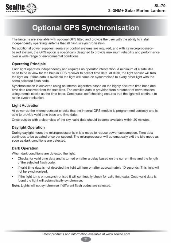
The lanterns are available with optional GPS fitted and provide the user with the ability to install independently operating lanterns that all flash in synchronisation.No additional power supplies, aerials or control systems are required, and with its microprocessor-based system, the GPS option is specifically designed to provide maximum reliability and performance over a wide range of environmental conditions.
Operating PrincipleEach light operates independently and requires no operator intervention. A minimum of 4 satellites need to be in view for the built-in GPS receiver to collect time data. At dusk, the light sensor will turn the light on. If time data is available the light will come on synchronised to every other light with the same selected flash code. Synchronisation is achieved using an internal algorithm based on the highly accurate time base and time data received from the satellites. The satellite data is provided from a number of earth stations using atomic clocks as the time base. Continuous self-checking ensures that the light will continue to run in synchronisation.
Light ActivationAt power-up the microprocessor checks that the internal GPS module is programmed correctly and is able to provide valid time base and time data. Once outside with a clear view of the sky, valid data should become available within 20 minutes.
Daylight OperationDuring daylight hours the microprocessor is in idle mode to reduce power consumption. Time data continues to be updated once per second. The microprocessor will automatically exit the idle mode as soon as dark conditions are detected.
Dark OperationWhen dark conditions are detected the light:• Checks for valid time data and is turned on after a delay based on the current time and the length
of the selected flash code;• If valid time data is not detected the light will turn on after approximately 10 seconds. This light will
not be synchronised. • If the light turns on unsynchronised it will continually check for valid time data. Once valid data is
found the light will automatically synchronise. Note: Lights will not synchronise if different flash codes are selected.
Optional GPS Synchronisation

Latest products and information available at www.sealite.com22
SL-70 2–3NM+ Solar Marine Lantern
Optional AvMesh® Monitoring & Control System
Sealite’s AvMesh® Monitoring and Control Systems may be fitted to the lantern enabling users to remotely modify the setup of their lantern via handheld radio controller.
Please contact Sealite for instructions on how to use the AvMesh® Monitoring & Control System.

Latest products and information available at www.sealite.com23
SL-70 2–3NM+ Solar Marine Lantern
Maintenance and ServicingDesigned to be maintenance free, the SL-70 requires minimal attention, though the following maintenance and servicing information is provided to help ensure the life of your Sealite product. 1. Cleaning Solar Panels - occasional cleaning of the solar panels may be required. Using a cloth and
warm soapy water, wipe off any foreign matter before rinsing the panels with fresh water. 2. Battery Check - inspection of batteries should be performed every three years (minimum) to ensure
that the charger, battery and ancillary electronics are functioning correctly. Using a voltage meter, check that the battery voltage is at least 3.6 volts under 100MA load, and ensure all terminals are clear of foreign matter.
Replacing the battery- Don’t throw the unit out!! The SL-70 lanterns are the only compact marine lantern with a double sealed battery compartment. This provides the user with the ability to change the battery after years of operation.1. Remove the marked flash adjustment bung from the base of the lantern and set internal toggle
switch to ‘OFF’.2. Unscrew small screws to remove battery plate. 3. Remove battery from SL-70 case and unscrew positive and negative leads. 4. Discard old battery in a safe manner. 5. Reattach positive and negative leads to new battery and then place back into case. 6. Reattach battery plate and switch lantern ‘ON’ via internal switch. Close the bung.7. To test place dark cover (towel or jacket) on top of lantern to activate sensor, lantern will come on.Care must be taken to observe the polarity of the battery before the leads are re-connected, and ensure the replacement battery is correctly fitted. Always discard old batteries in a safe manner.
Long Term Storage InstructionsIf the SL-70 is to be placed in storage for an extended period, being more than 5 months, please follow the below steps.1. The 3.6V NiMH Battery must be stored in a fully charged condition.2. Remove the Flash Adjustment plug and turn the ON/OFF switch to the OFF position.3. Remove the battery cover and disconnect the Positive (+) Terminal.4. Fold the Terminal away from the Negative Battery Terminal. 5. Replace the Battery Cover6. Replace the Flash Adjustment Plug.All batteries will discharge over time and the rate of discharge is dependent on temperature. If the lantern is being stored in temperatures greater than 40°C the battery will discharge faster.Please check battery every 3-6 months and recharge if necessary.
Recharging the Battery1. Remove the Battery Cover and connect the Positive Terminal.2. Remove the Flash Adjustment Plug and turn the ON/OFF switch to the ON position.3. Reconnect the Light Head and place unit in the sun for 2-4 daysOrReconnect Light Head and place in front of a halogen lamp for 2-3 days. (Do not place the halogen light too close to the solar panel or the panel may be overheated)
Check the battery voltage regularly to make sure the unit is charging correctly.After the battery has been recharged, switch the lantern OFF.

Latest products and information available at www.sealite.com24
SL-70 2–3NM+ Solar Marine Lantern
Trouble Shooting
Problem RemedyLantern will not activate. • Ensure internal toggle switch is set to the ‘ON position.
• Ensure lantern is in darkness.• Wait at least 60 seconds for the program to initialise in darkness.• Ensure switch setting is on a valid code (See ‘Flash Codes’ section of
this manual).• Ensure battery terminals are properly connected.• Ensure battery voltage is above 3.4volts.
Timing codes will not change. • Turn rotary switches several times to ensure contacts are clear.
Lantern will not operate for the entire night.
• Expose lantern to direct sunlight and monitor operation for several days. Sealite products typically require 1.5 hours of direct sunlight per day to retain full autonomy. From a discharged state, the lantern may require several days of operational conditions to ‘cycle’ up to full autonomy.
• Reducing the light output intensity or duty cycle (flash code) will reduce current draw on the battery.
• Ensure solar module is clean and not covered by shading during the day.
Lanterns are constantly on during the day.
• Ensure the flash code is not set to F F. This flash code is for testing purposes only and will be steady on for 24 hours a day.

Latest products and information available at www.sealite.com25
SL-70 2–3NM+ Solar Marine Lantern
Notes
Latest products and information available at www.sealite.com26
SL-70 2–3NM+ Solar Marine Lantern
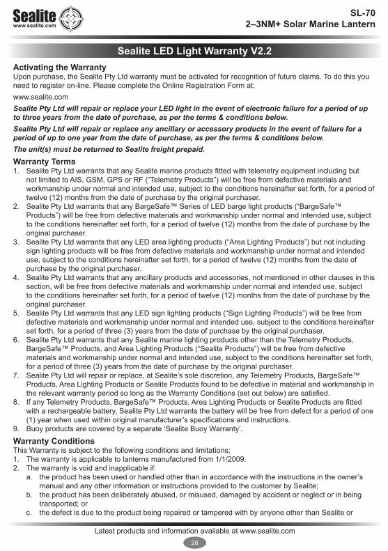
Activating the WarrantyUpon purchase, the Sealite Pty Ltd warranty must be activated for recognition of future claims. To do this you need to register on-line. Please complete the Online Registration Form at:www.sealite.comSealite Pty Ltd will repair or replace your LED light in the event of electronic failure for a period of up to three years from the date of purchase, as per the terms & conditions below.Sealite Pty Ltd will repair or replace any ancillary or accessory products in the event of failure for a period of up to one year from the date of purchase, as per the terms & conditions below.The unit(s) must be returned to Sealite freight prepaid.Warranty Terms 1. Sealite Pty Ltd warrants that any Sealite marine products fitted with telemetry equipment including but
not limited to AIS, GSM, GPS or RF (“Telemetry Products”) will be free from defective materials and workmanship under normal and intended use, subject to the conditions hereinafter set forth, for a period of twelve (12) months from the date of purchase by the original purchaser.
2. Sealite Pty Ltd warrants that any BargeSafe™ Series of LED barge light products (“BargeSafe™ Products”) will be free from defective materials and workmanship under normal and intended use, subject to the conditions hereinafter set forth, for a period of twelve (12) months from the date of purchase by the original purchaser.
3. Sealite Pty Ltd warrants that any LED area lighting products (“Area Lighting Products”) but not including sign lighting products will be free from defective materials and workmanship under normal and intended use, subject to the conditions hereinafter set forth, for a period of twelve (12) months from the date of purchase by the original purchaser.
4. Sealite Pty Ltd warrants that any ancillary products and accessories, not mentioned in other clauses in this section, will be free from defective materials and workmanship under normal and intended use, subject to the conditions hereinafter set forth, for a period of twelve (12) months from the date of purchase by the original purchaser.
5. Sealite Pty Ltd warrants that any LED sign lighting products (“Sign Lighting Products”) will be free from defective materials and workmanship under normal and intended use, subject to the conditions hereinafter set forth, for a period of three (3) years from the date of purchase by the original purchaser.
6. Sealite Pty Ltd warrants that any Sealite marine lighting products other than the Telemetry Products, BargeSafe™ Products, and Area Lighting Products (“Sealite Products”) will be free from defective materials and workmanship under normal and intended use, subject to the conditions hereinafter set forth, for a period of three (3) years from the date of purchase by the original purchaser.
7. Sealite Pty Ltd will repair or replace, at Sealite’s sole discretion, any Telemetry Products, BargeSafe™ Products, Area Lighting Products or Sealite Products found to be defective in material and workmanship in the relevant warranty period so long as the Warranty Conditions (set out below) are satisfied.
8. If any Telemetry Products, BargeSafe™ Products, Area Lighting Products or Sealite Products are fitted with a rechargeable battery, Sealite Pty Ltd warrants the battery will be free from defect for a period of one (1) year when used within original manufacturer’s specifications and instructions.
9. Buoy products are covered by a separate ‘Sealite Buoy Warranty’.
Warranty ConditionsThis Warranty is subject to the following conditions and limitations; 1. The warranty is applicable to lanterns manufactured from 1/1/2009.2. The warranty is void and inapplicable if:
a. the product has been used or handled other than in accordance with the instructions in the owner’s manual and any other information or instructions provided to the customer by Sealite;
b. the product has been deliberately abused, or misused, damaged by accident or neglect or in being transported; or
c. the defect is due to the product being repaired or tampered with by anyone other than Sealite or
Sealite LED Light Warranty V2.2

Latest products and information available at www.sealite.com27
SL-70 2–3NM+ Solar Marine Lantern
Information in this manual is subject to change without notice and does not represent a commitment on the part of the vendor. Sealite products are subject to certain Australian and worldwide patent applications.
authorised Sealite repair personnel. 3. The customer must give Sealite Pty Ltd notice of any defect with the product within 30 days of the
customer becoming aware of the defect. 4. Rechargeable batteries have a limited number of charge cycles and may eventually need to be replaced.
Typical battery replacement period is 3-4 years. Long term exposure to high temperatures will shorten the battery life. Batteries used or stored in a manner inconsistent with the manufacturer’s specifications and instructions shall not be covered by this warranty.
5. No modifications to the original specifications determined by Sealite shall be made without written approval of Sealite Pty Ltd.
6. Sealite lights can be fitted with 3rd party power supplies and accessories but are covered by the 3rd party warranty terms and conditions.
7. The product must be packed and returned to Sealite Pty Ltd by the customer at his or her sole expense. Sealite Pty Ltd will pay return freight of its choice. A returned product must be accompanied by a written description of the defect and a photocopy of the original purchase receipt. This receipt must clearly list model and serial number, the date of purchase, the name and address of the purchaser and authorised dealer and the price paid by the purchaser. On receipt of the product, Sealite Pty Ltd will assess the product and advise the customer as to whether the claimed defect is covered by this warranty.
8. Sealite Pty Ltd reserves the right to modify the design of any product without obligation to purchasers of previously manufactured products and to change the prices or specifications of any product without notice or obligation to any person.
9. Input voltage shall not exceed those recommended for the product.10. Warranty does not cover damage caused by the incorrect replacement of battery in solar lantern models.11. This warranty does not cover any damage or defect caused to any product as a result of water flooding or
any other acts of nature.12. There are no representations or warranties of any kind by Sealite or any other person who is an agent,
employee, or other representative or affiliate of Sealite, express or implied, with respect to condition of performance of any product, their merchantability, or fitness for a particular purpose, or with respect to any other matter relating to any products.
Limitation of LiabilityTo the extent permitted by acts and regulations applicable in the country of manufacture, the liability of Sealite Pty Ltd under this Warranty will be, at the option of Sealite Pty Ltd, limited to either the replacement or repair of any defective product covered by this Warranty. Sealite will not be liable to Buyer for consequential damages resulting from any defect or deficiencies.
Limited to Original Purchaser This Warranty is for the sole benefit of the original purchaser of the covered product and shall not extend to any subsequent purchaser of the product.
MiscellaneousApart from the specific warranties provided under this warranty, all other express or implied warranties relating to the above product is hereby excluded to the fullest extent allowable under law. The warranty does not extend to any lost profits, loss of good will or any indirect, incidental or consequential costs or damages or losses incurred by the purchaser as a result of any defect with the covered product.
WarrantorSealite Pty Ltd has authorised distribution in many countries of the world. In each country, the authorised importing distributor has accepted the responsibility for warranty of products sold by distributor. Warranty service should normally be obtained from the importing distributor from whom you purchased your product. In the event of service required beyond the capability of the importer, Sealite Pty Ltd will fulfil the conditions of the warranty. Such product must be returned at the owner’s expense to the Sealite Pty Ltd factory, together with a photocopy of the bill of sale for that product, a detailed description of the problem, and any information necessary for return shipment.

SL-70 2–3NM+ Solar Marine Lantern
Other Sealite Products Available
AUSTRALIAt: +61 (0)3 5977 6128
USAt: +1 (603) 737 1311
UNITED KINGDOMt: +44 (0) 1502 588026
We believe technology improves navigation™e: [email protected]
Marine Lanterns (1–19NM)
Bridge & Barge Lights
Area Lighting
Monitoring & Control Systems
Marine Buoys(up to 3mt in diameter)
Mooring Systems & Accessories