seahawk manual new - free energy storegenerator. the cage assembly on the seahawk is the new...
TRANSCRIPT

PacWind SeaHawk
12, 24 or 48 VDC Battery Charging System
Owners Manual
PacWind, Inc. 23930 Madison Street,
Torrance, CA 90505 USA Telephone: (310) 375-9952
Fax: (310) 375-2331 E-mail: [email protected]
Web: www.pacwind.net
SeaHawk Vertical Axis Wind Turbine MorningStar TriStar-60 Controller
Version 1.0 July 2006

1 SeaHawk Vertical Axis Wind Turbine
12, 24 or 48V Battery Charging System
OWNERS MANUAL
Table of Contents Page #
1. Overview 2
2. Cautions and Warnings 3
3. Identification 4
4. System Description 4
5. System Operation 6
6. Turbine Installation 8
7. MorningStar Installation 9
8. Trouble-Shooting 10 APPENDICES
Appendix 1 Installation Planning 11
Appendix 2 SeaHawk Specifications 16
Appendix 3 Basic Tower Requirements 18
Appendix 4 Disclaimer 20

1. Overview The SeaHawk vertical axis wind turbine system is a state of-the-art small generator designed to charge batteries and supply electrical loads in a 12, 24 or 48 V D.C. bus based remote power systems. The voltage system you choose is based upon your average wind speed according to the following chart: Average Wind Speed Optimum System Voltage 0-5.4 m/s (0-12 mph) 12 Volts 5.4-10.8 m/s (12-24 mph) 24 Volts 10.8 m/s (24 mph) and greater 48 Volts Multiple SeaHawk Turbines can be connected in parallel for more power output as needed. When used in conjunction with a suitable sine wave DC-AC inverter and a 12, 24 or 48 VDC battery bank the SeaHawk can also be connected to the power grid. The SeaHawk turbine consists of a .762 meter x 1.2 meter (2.5 ft. diameter, 4 ft. high), 63.5 -kilograms (140 lb) wind turbine rated at 1,000 watts and a multi-function turbine and system controller made by MorningStar Corp. - the TriStar-60. The SeaHawk vertical axis wind turbine features low wind speed performance, very high system efficiency, and no noise. The MorningStar Corp. - TriStar-60 features a solar regulator, a dump load capability, an automated time-based equalization function, and special circuitry to monitor the SeaHawk and battery performance with remote capabilities. The SeaHawk is offered with optional tilt-over towers, which come in heights from 9 m (30 ft.) to 32 m (104 ft.). The tilt-over towers are shown in Figure 1. For installation procedures on these towers, please refer to the “PacWind Tilt-Over Tower Installation Manual”. This manual is available on-line at http://www.pacwind.net and from PacWind dealers, and from PacWind directly.
Figure 1, SeaHawk with 9 m Tilt Tower
2. Cautions and Warnings This manual contains important information on the installation of your SeaHawk vertical axis wind turbine and MorningStar TriStar-60 controller. We strongly recommend that you read and follow the instructions contained in this manual. At several points in the manual items of special interest or significant impact are highlighted by one of the following notices.
Hazards or unsafe practices that could cause personal injury or death.
Caution Hazards or unsafe practices that could cause product damage.
Note Significant points of interest 3. Identification Each SeaHawk vertical axis wind turbine has a serial number located on the bottom of the generator. The Serial Number is also written on the box that the turbine came in. We recommend writing it here as well: PacWind SeaHawk Serial No.: 4. System Description SeaHawk Vertical Axis Wind Turbine Components The major components of the SeaHawk wind turbine are shown in Figure 2.
A. Blades / Cage System

The rotor cage system consists of six blades of extruded PVC. Acting like aircraft wings, the blades convert the energy of the wind into rotational forces that drive the permanent magnet generator. The cage assembly on the SeaHawk is the new patented design by PacWind, Inc. The PVC blades are exceptionally strong, but flexible to withstand high winds and for resisting ice and snow buildup. The cage assembly has six blades that have exceptional wind capture. The cage assembly also is seen by birds as a solid object so they avoid flying into the turbine. The system generates no noise or vibration, so wildlife (or your neighbors) is unlikely to object to the presence of the SeaHawk.
Figure 2, Major Components of the SeaHawk Wind Turbine The Permanent Magnet Generator (PMG) converts the rotational energy of the rotor into electricity. The PMG is a direct drive generator with one moving part. The PMG was specially designed for the SeaHawk and produces power at low speeds, eliminating the need for a speed increasing gearbox. The output from the generator is three-phase alternating current (AC), but it is rectified to direct current inside the PMG housing. Since it uses permanent magnets, the PMG is generating voltage whenever the rotor is turning.
B. VAWT Assembly The SeaHawk VAWT is easily assembled, as the only assembly required is to attach the cage assembly to the PMG. This is accomplished by placing the PMG on a flat surface, setting the cage assembly (the side with the holes) on top of the PMG and taking a #1 phillips screwdriver and placing it in one of the cage holes to line it up with one of the tapped holes in the PMG. Once aligned place one of the 5/16”-18 x 1 1/4” hex head bolts in any one of the other holes and finger tighten. Remove the alignment screwdriver and place the other bolts in the remaining holes and finger tighten. Be sure to use a split ring washer and a flat washer on each bolt. Using a ¼” Hex

Head Allen wrench, tighten one bolt until the split-ring washer is flat. Then tighten the bolt on the opposite side of the cage. Repeat the sequence with the next bolt over until all eight bolts are tight. This completes the VAWT assembly.
W The output wiring of the SeaHawk presents a low voltage shock hazard whenever the rotor is turning at significant speeds. Caution must be exercised at all times to avoid electrical shock.
5. SYSTEM OPERATION A. Normal Operation The rotor of the SeaHawk should begin to rotate when the wind speed reaches approximately 1.8 m/s 4 mph. Battery charging will commence on a 12 Volt battery system at about 3.1 m/s (7 mph), on a 24 Volt battery system at about 5.4 m/s (12 mph) and on a 48 Volt battery system at about 10.8 m/s (24 mph).
Note All operational wind speeds given assume steady winds, sea-level altitude and moderate temperatures. Hot weather, high altitude, turbulence, and gusting winds will reduce system performance. The rotor speed will increase with increasing wind speed and the system will provide a higher output. This output increases rapidly because the energy available in the wind varies as the third power (cube) of the wind speed. For example, if the wind speed doubles from 5 m/s (11.2 mph) to 10 m/s (22.4 m/s), the energy in the wind increases by a factor of eight (23 = 2 x 2 x 2 = 8). One result of this relationship is that there is very little energy available in light winds. For the average site, winds in the range of 5.5 – 9 m/s (12 – 20 mph) will provide most of the system’s annual energy production. B. High Winds The SeaHawk VAWT performs extremely well under high wind conditions. Since there is no need to protect itself as do propeller based systems, the SeaHawk simply cannot spin any faster at above about 42.75 m/s (95 mph). The SeaHawk just appears as wind loading at that point and the wind simply goes around the SeaHawk as it is putting out full power. The SeaHawk puts out maximum power at about 27 m/s (60 mph).
Caution Do not install the SeaHawk wind turbine near cliffs or precipices or on sharp hills such that the wind does not travel horizontally through the rotor.

D. SeaHawk Wiring The basic electrical schematic for the SeaHawk is shown in Figure 5. The SeaHawk’s PMG produces three-phase alternating current (AC) that varies in voltage and frequency with the rotor speed. The AC power is rectified to direct current (DC) power by a rectifier module inside the PMG. Thus, the wire run from the wind turbine to the MorningStar TriStar TS-60 is DC.
Figure 5, SeaHawk Basic Electrical Schematic
E. MorningStar TriStar TS-60 Controller The complete SeaHawk VAWT wind power system consists of the SeaHawk VAWT, the included MorningStar TriStar TS-60 Controller, an optional 12, 24 or 48 Volt battery bank and an optional dump load. The SeaHawk system automatically supports optional Photo-Voltaic (PV) solar arrays and connections for the optional solar systems are included in the MorningStar TriStar TS-60 Controller manual. The basic connections from the SeaHawk to the MorningStar TriStar TS-60 Controller are shown in Figure 6. The operating manual for the MorningStar TriStar TS-60 Controller is included with the SeaHawk VAWT. Operational settings and controls for 12, 24 and 48 Volt battery banks is contained within the MorningStar TriStar TS-60 Controller manual. If you require additional information that you cannot find in the MorningStar TriStar TS-60 Controller manual, please call the PacWind factory for support.

Figure 6, SeaHawk System Connections 6. Turbine Installation Appendix 1 is an Installation Planning Guide. It provides recommendations on tower heights and locations, electrical components, and wiring. Tower Mounting: The SeaHawk wind turbine is attached to its tower by pipe adapters, shown in Figure 7, that are designed to fit inside pipes with inner diameters of 88.9 mm (3.5 in), 127 mm (5 in), or 203.2 mm (8 in). If you are using the SeaHawk Tilt.Tower then the SeaHawk will bolt directly in place. If you are mounting the SeaHawk to a different type of tower then you will need to ensure that the tower meets the requirements for SeaHawk towers (see Appendix) and that it has a proper adapter fitting for attaching the SeaHawk tower mount casting (also defined in the Appendix). Once you have the proper mounting arrangement you can proceed with assembly of the wind turbine. The fasteners on the SeaHawk are all metric.

Figure 7, Tower Mounting adapters for the SeaHawk VAWT
7. MorningStar TriStar TS-60 Controller Installation A. Electrical System The general electrical configuration for SeaHawk and hybrid system installations is shown in Figure 8. In most cases the loads will be D.C. and can be directly connected to the battery bank.
Figure 8, Typical SeaHawk System Configuration
B. Location The MorningStar TriStar TS-60 Controller and associated electronics must be installed indoors or in a NEMA 5 rated outdoor enclosure and should be located relatively close to the battery bank. For battery installations, please follow the battery manufacturer instructions. Ensure that the battery is disconnected before installing or making changes to any wiring. C. Mounting: The MorningStar TriStar TS-60 Controller should to be mounted vertically to a wall, or other support structure, so that air can pass unobstructed through the passive cooling channel behind the enclosure. We recommend setting the height of the LED’s at eye level if possible so that the system status lights will be easiest to read. The enclosure location and typical mounting layout for the MorningStar TriStar TS-60 Controller are shown in Figure 8. The MorningStar TriStar TS-60 Controller should be mounted per the instructions located in the MorningStar TriStar TS-60 Controller manual. C. Wiring All wiring should conform to the National Electric Code or other governing local electrical code. The use of electrical conduit for wiring between components is highly recommended. If you have any connections with dissimilar metals (aluminum to copper) they should be coated with an antioxidation compound to prevent galvanic corrosion. All loads should be protected by fuses or circuit breakers to avoid hazards from accidental short circuits. The wind turbine tower must be well grounded and a good quality lightning surge arrestor, connected to a good quality earth ground, should be installed on the wiring from the wind turbine. We recommend a Delta LA302DC arrestor installed into the third (from the left) rear entrance hole of the enclosure. This tucks the arrestor neatly behind the enclosure. The arrestor leads are connected to the wind turbine terminals. The MorningStar TriStar TS-60 Controller has a built in ground, all circuits are floating, such that either the positive or the negative can be grounded. Some inverter manufacturers recommend grounding and some electrical codes require it. If you do ground the MorningStar TriStar TS-60 Controller, please conform to local practices for grounding either the positive or negative bus. All negative leads are connected together on the MorningStar TriStar TS-60 Controller circuit board, so grounding the battery negative lead, will ground the turbine negative, the PV negative, and the dump load negative as well. This is the preferred grounding method; the enclosure should also be grounded, by bolting a box lug to it in a convenient location. 8. Trouble-Shooting Problems A basic trouble-shooting guide is located in the MorningStar TriStar TS-60 manual. For operational problems with the SeaHawk wind and for problems or symptoms not found in the MorningStar TriStar TS-60 manual, please contact the Service Department at PacWind at: Tel: 310-375-9952 Fax: 310-375-2331 E-mail: [email protected]
Appendices Appendix 1 Installation Planning The location and height of the tower for the PacWind SeaHawk wind system will be important factors in determining the overall performance of the system. Average wind speed is influenced by many things and may vary considerably within a relatively small region, particularly in complex terrain. Site and tower choice, however, are often limited by such factors as zoning restrictions, property size, proximity to neighbors, customer preferences, and wiring costs. All of these factors should be taken into consideration in choosing the best tower site and height. A. Legal Restrictions and Good Neighbor Relations One of the first steps in planning an installation is to determine the legal status of the proposed wind turbine installation in the community in which it will be installed. In most cities and some counties an installation will be subject to zoning laws and building codes. Some neighborhoods have protective covenants that limit the types of home improvements. In areas requiring permits the installation must be planned weeks to months in advance to allow time for applications to be processed and, if necessary, hearings to be held. The quickest way to determine the local codes and requirements is to call or visit the office of the building inspector. Few cities have specific regulations dealing with wind turbines, but most will have height restrictions, building code requirements, and a formal process for obtaining a building permit. The most common problem encountered in the United States is a height restriction of 10.7 meters (35 feet), particularly in residentially zoned areas. The 9 m (30 ft) Tilt Tower meets the 35 ft restriction with reasonable performance. If you need or want to go higher than the zoning height restriction you must apply for a variance. A variance is essentially permission to break a rule and it is granted following a public hearing before a Planning Board. Obtaining a variance is a major undertaking, costing $200-5,000 and taking several months, so it is important to establish whether it will be necessary as soon as possible. PacWind has experience in working with customers and SeaHawk dealers in variance hearings and we offer advice and assistance to those who request it. Generally, in order to obtain a building permit you will be required to submit a plot plan and fill out an application. A plot plan is a map, drawn to scale, of your property showing the boundaries, dwelling( s) and other structures, major topographic features, easements, and, most importantly, the location and height of the proposed wind turbine tower. Often you will be required to submit plans for the tower and information on the wind turbine. In some cases you will also be required to submit a structural analysis of the tower to show that it is in compliance with the building code. Sometimes a registered Professional Engineer (PE) must sign this analysis and occasionally the PE must be licensed in the State where the unit will be installed.

PacWind has engineering analyses, PE-Certified, for most towers it offers and copies of these analyses are available to our customers. Noise data is available for the SeaHawk from PacWind. If your property size is several acres or more then the turbine will likely be so far from the nearest neighbor’s house that they will not be bothered. It is, none the less, strongly recommended that you contact your nearest neighbors well in advance of any construction to let them know that you are installing a wind turbine. This is doubly good advice if your property size is less than several acres or you have to obtain a variance for a building permit. Good neighbor relations boil down to treating your neighbors the same way you would like to be treated and showing respect for their views. An example of what not to do is to put the turbine on your property line so that it is closer to a neighbor’s house than to your own and not give those neighbors any advance notice of your intentions. In general, we do not recommend that a SeaHawk be installed on property of less than one-half acre in size. We say this because the impact of a wind turbine on the neighbors in such a “tight” area is significant and the potential for disputes is too great. If you have questions about procedures, requirements, or tactics, please contact us. Since so few wind systems have been installed and communities are generally unfamiliar with them, you may face some obstacles in gaining permission to install a unit. We appreciate the pioneering spirit and resolve demonstrated by our customers and we stand ready to help out in any way that we can. B. Towers The smooth flow of the wind over the land is interrupted by obstructions and topographical variations. These interruptions bring about two important phenomena: wind shear and turbulence. Wind shear describes the fact that close to the ground the wind is slowed down by friction and the influence of obstacles. Thus, wind speed is low close to the ground and increases with increasing height above the ground. Wind shear is more pronounced over rough terrain and less pronounced over smooth terrain. Turbulence is essentially rough air caused by the wind passing over obstructions such as trees, buildings, or terrain features. Turbulent air reduces energy output and puts greater strain on the wind turbine. The effects of both wind shear and turbulence diminish with height and can be largely overcome simply by putting the machine sufficiently high above the ground. Taller towers usually will provide better economics because the power in the wind increases as the cube of the wind velocity (P = V3; e.g., a 26% increase in wind speed doubles the energy output). A small increase in average wind speed will result in a large increase in long term energy output. Table 2 shows the influence that tower height can have on annual energy output for the SeaHawk wind turbine under typical DOE Class 2 inland site conditions with a shear exponent of 0.20. Wind speed may increase more radically with tower height in hilly or wooded areas. In flat open areas, power production will increase less significantly with tower height. The SeaHawk wind turbine must be placed on a tower that is tall enough to give the cage proper exposure to the wind. Putting a wind turbine on a tower that is too short is like installing a solar system in the shade. As a “rule-of-thumb” the SeaHawk should be 9 m (30 ft) above obstacles within 50 m (160 ft), particularly in the prevailing wind direction. So, the minimum recommended tower height is 9 m (30 ft.). For most situations, a tower of at least 18 m (60 ft.) is recommended for this unit. Energy
Production
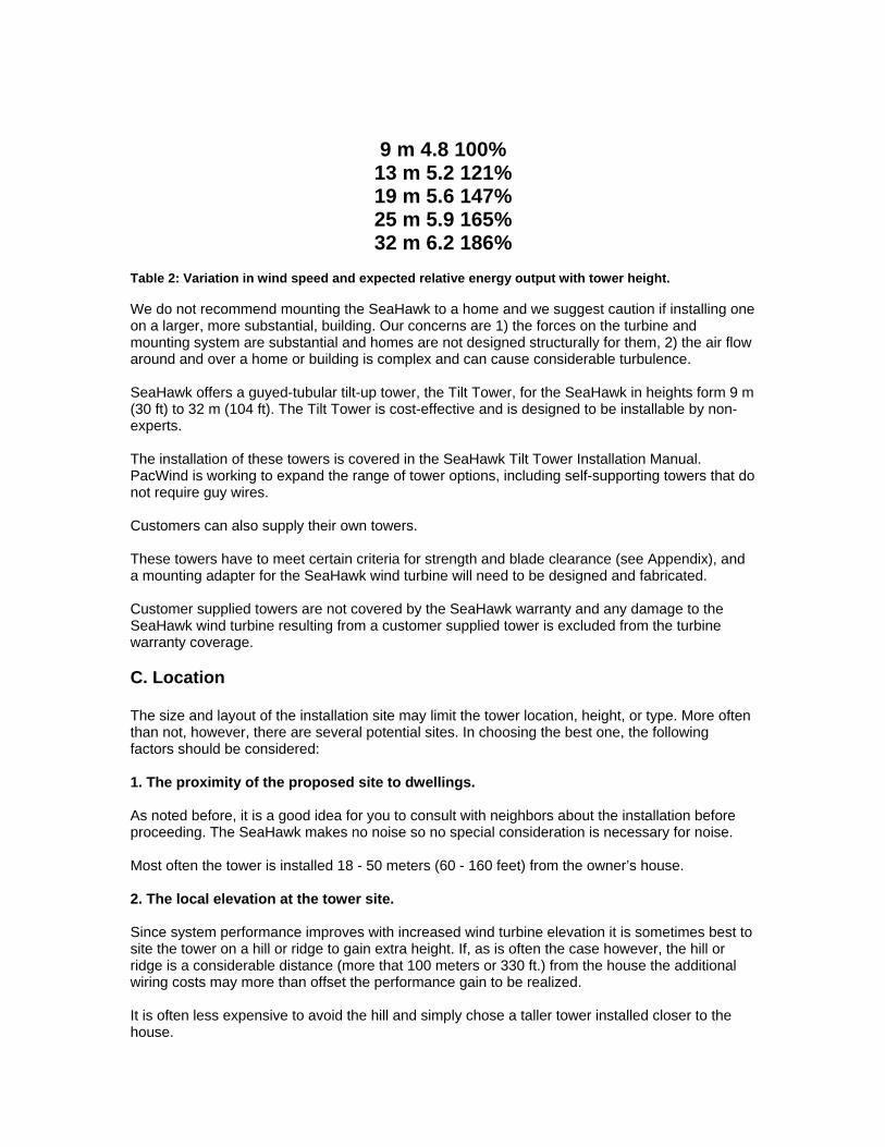
9 m 4.8 100% 13 m 5.2 121% 19 m 5.6 147% 25 m 5.9 165% 32 m 6.2 186%
Table 2: Variation in wind speed and expected relative energy output with tower height. We do not recommend mounting the SeaHawk to a home and we suggest caution if installing one on a larger, more substantial, building. Our concerns are 1) the forces on the turbine and mounting system are substantial and homes are not designed structurally for them, 2) the air flow around and over a home or building is complex and can cause considerable turbulence. SeaHawk offers a guyed-tubular tilt-up tower, the Tilt Tower, for the SeaHawk in heights form 9 m (30 ft) to 32 m (104 ft). The Tilt Tower is cost-effective and is designed to be installable by non-experts. The installation of these towers is covered in the SeaHawk Tilt Tower Installation Manual. PacWind is working to expand the range of tower options, including self-supporting towers that do not require guy wires. Customers can also supply their own towers. These towers have to meet certain criteria for strength and blade clearance (see Appendix), and a mounting adapter for the SeaHawk wind turbine will need to be designed and fabricated. Customer supplied towers are not covered by the SeaHawk warranty and any damage to the SeaHawk wind turbine resulting from a customer supplied tower is excluded from the turbine warranty coverage. C. Location The size and layout of the installation site may limit the tower location, height, or type. More often than not, however, there are several potential sites. In choosing the best one, the following factors should be considered: 1. The proximity of the proposed site to dwellings. As noted before, it is a good idea for you to consult with neighbors about the installation before proceeding. The SeaHawk makes no noise so no special consideration is necessary for noise. Most often the tower is installed 18 - 50 meters (60 - 160 feet) from the owner’s house. 2. The local elevation at the tower site. Since system performance improves with increased wind turbine elevation it is sometimes best to site the tower on a hill or ridge to gain extra height. If, as is often the case however, the hill or ridge is a considerable distance (more that 100 meters or 330 ft.) from the house the additional wiring costs may more than offset the performance gain to be realized. It is often less expensive to avoid the hill and simply chose a taller tower installed closer to the house.

3. The length of the wire run. While is possible to install wire runs (the wiring between the wind turbine and the wind turbine electronics) of several hundred meters (650 ft) or more, the costs for long wire runs, particularly if they are buried, can be prohibitive. The longer the wire run, the larger and more expensive the wire that is required to conduct the electricity with acceptable losses. As a general rule, wire runs over 100 meters (330 ft.) if buried or 200 meters (650 ft.) if installed overhead should be avoided because of their high costs. On the SeaHawk it is not possible to use transformers to increase the wire run voltage because the wire run is direct current (DC). Transformers only work with alternating current (AC). 4. General convenience. Often the most compelling consideration for locating the wind turbine tower is the space where it will not interfere with vehicle traffic, fence lines, crops, gardens, septic system lateral lines, power poles, etc. Since the wind turbine installation is semi-permanent, your future plans for the property should also be taken into consideration. When using a Tilt Tower you should consider the extra space needed for the tower when its is tilted down. 5. Safety The SeaHawk should never be installed close to a power line. We recommend that the tower be at least 1 ½ times the height of the tower from any power line including any overhead service line bringing power to your home.
Warning Although the SeaHawk contains metal, which readily conducts electricity, the cage assembly is surrounded by non-conducting materials, however, if any part of the wind turbine that contains metal or the tower it’s mounted on makes contact with power lines there is a risk of electrocution. We also recommend that any guy wire anchors be kept away from roads or paths used by vehicles. D. Wiring The basic electrical schematic for the SeaHawk battery charging system is shown in Figure 5. The wind turbine alternator produces 3-phase AC, which is rectified into DC in the PMG. A two (2)- conductor wire is needed between the wind turbine and the MorningStar TriStar TS-60 Controller. The MorningStar TriStar TS-60 Controller requires a fuse for the wind turbine input, so a fused-disconnect switch is recommended at the base of the tower per the MorningStar TriStar TS-60 Controller manual. We recommend that the tower wiring be with SO cord. The SO cord’s neoprene jacket will provide good abrasion resistance. For ground runs we recommend THHN wire buried inside plastic conduit rated for electrical service. A suitable watertight junction box should be installed at the base of the tower to enclose the wire connections between the tower and underground wiring. In some cases it will be possible to provide direct point-to-point wiring between the SeaHawk wind turbine and the MorningStar TriStar TS-60 Controller. For this purpose we recommend 2-conductor VNTC (Vinyl Nylon Tray Cable), which is suitable for outdoor and direct burial

applications. For rocky soils, or runs underneath roadways, we recommend that the underground wire run be installed in conduit. If a wiring junction is made at the base of the tower then a watertight junction box should be installed for the connections. The recommended wire sizes for the SeaHawk wind turbine are shown in Table 3. The listed distances include the height of the tower. Maximum Current: 60 amps
Caution Installing wire sizes larger than those recommended will increase the maximum current produced by the turbine. WIRE SIZE DISTANCE FROM TURBINE TO THE MORNINGSTAR TRISTAR TS-60 CONTROLLER MM^2 AWG METERS FEET 10 8 AWG 0 - 35 0 - 116 16 6 AWG 36 - 56 117 - 183 25 4 AWG 57 - 89 184 - 292 30 3 AWG 90 - 112 293 - 368 35 2 AWG 113 - 141 369 - 464 50 1 AWG 142 - 178 465 - 585 55 1/0 AWG 179 - 225 586 - 739 70 2/0 AWG 226 - 287 740 - 940 95 3/0 AWG 288 - 361 941 - 1185 120 4/0 AWG 362 - 455 1186 – 1494 Table 3: Recommended Wire Sizes for the SeaHawk Note: These wire sizes have been engineered to provide optimum rotor loading for the SeaHawk wind turbine. Deviation from these recommendations can result in decreased performance from your machine and / or unnecessary additional wire-run costs. The use of a wire gage one size larger than the recommended size is recommended if aluminum wire is used. Before assembling the wind turbine the tower wiring must be in place, though not necessarily permanently affixed. We recommend that you leave at least 30 cm (12 in) of free wire at the top of the tower for making the electrical connections to the wind turbine. E. Other System Components A complete remote power system will include other electrical components such as a solar array (optional), a battery bank (required), a dump load (optional), and an inverter (optional). These components are sometimes called the “balance of system” or BOS equipment. The wind turbine and the other BOS equipment are electrically connected in a “DC-bus” architecture, as shown in Figure 6. The DC-bus architecture is robust and very flexible, allowing endless options for multiple and differing components. The unifying feature is that all of these components are electrically connected to the positive (+)

and negative (-) DC bus, so they all experience the same DC voltage. The DC voltage of the system is largely determined by the state of charge of the battery bank and to a lesser, but still significant, extent by the charging or discharging rates (the rate at which DC current, or amps, is being created or consumed). Charging components, such as wind turbines, solar arrays, and inverter/chargers (powered by a back-up generator or the power grid), can be added to a DC-bus system with separate charge regulators and these regulators can operate completely autonomously (e.g., they do not need to communicate with each other or be coordinated using a central system controller). The separate charge regulators, whether there is just one or if there are a dozen, will respond to the DC-bus voltage and control their generators charging current. When putting together or adding to a DC-bus remote power system there are a few pitfalls to avoid if possible: • Battery banks that are too small, so that battery voltage swings too much with high charging or discharging currents. • Multiple charge regulators set to the same voltage, so that there is one big step in charging current rather than several smaller ones. • Setting high voltage regulation points too low so that the batteries don’t get fully charged • Setting the low voltage disconnect (typically part of the inverter) too high so that the battery bank capacity is underutilized
Appendix 2 SEAHAWK SPECIFICATIONS TURBINE: • CAGE DIAMETER 76.2 MM 2.5 FT • OVERALL LENGTH 120 MM 4.0 FT • TURBINE WEIGHT 35.8 KG 140 LB • RATED POWER 1,000 W • RATED WINDSPEED 19.3 M/S 43 MPH • RATED ROTOR SPEED 608 RPM • START-UP WINDSPEED 1.35 M/S 3.0 MPH • CUT-IN WINDSPEED 3.6 M/S 8.0 MPH • MAX DESIGN WINDSPEED 54 M/S 120 MPH • MAX POWER OUTPUT 3.40 kW • TURBINE INPUT FUSE 60 AMPS • BATTERY FUSE 90 AMPS • OPTIONAL PHOTOVOLTAIC INPUT FUSE 30 AMPS • DUMP LOAD FUSE 60 AMPS
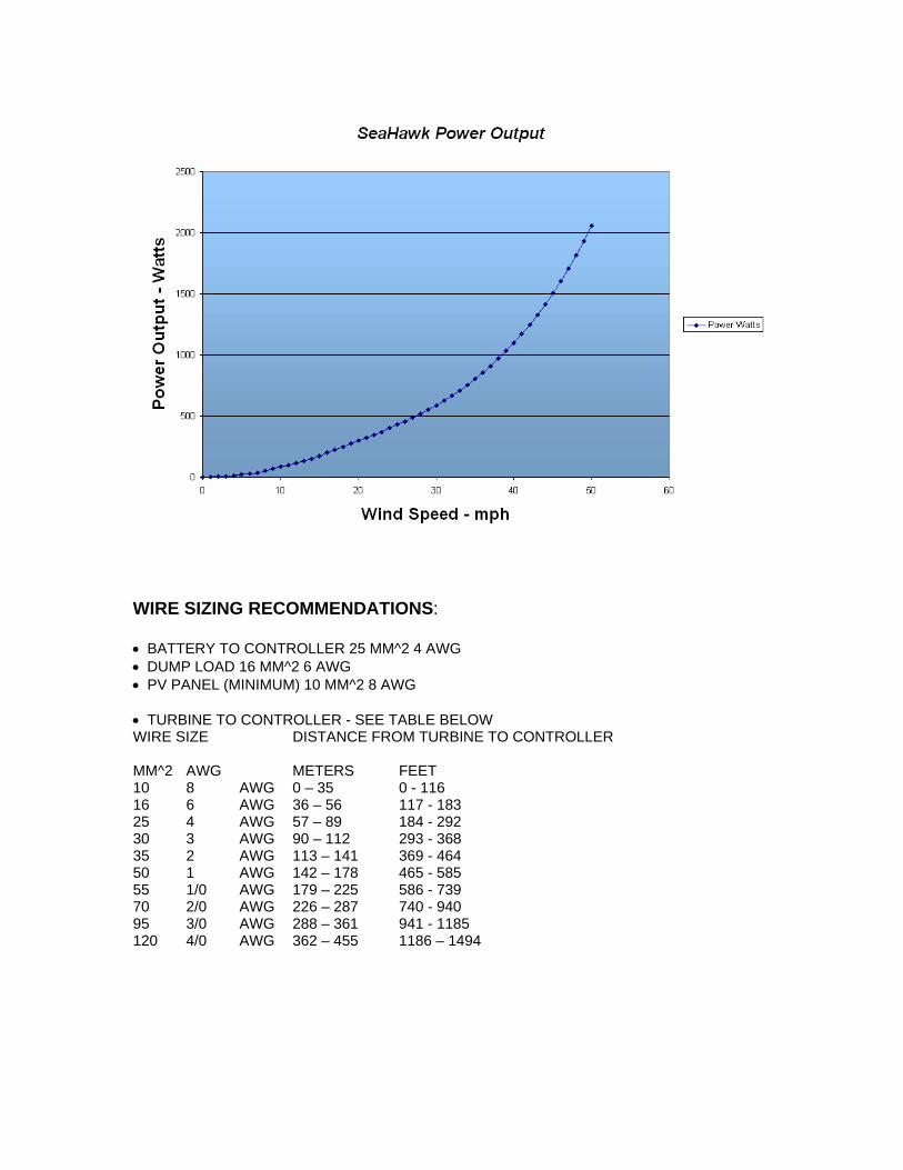
WIRE SIZING RECOMMENDATIONS: • BATTERY TO CONTROLLER 25 MM^2 4 AWG • DUMP LOAD 16 MM^2 6 AWG • PV PANEL (MINIMUM) 10 MM^2 8 AWG • TURBINE TO CONTROLLER - SEE TABLE BELOW WIRE SIZE DISTANCE FROM TURBINE TO CONTROLLER MM^2 AWG METERS FEET 10 8 AWG 0 – 35 0 - 116 16 6 AWG 36 – 56 117 - 183 25 4 AWG 57 – 89 184 - 292 30 3 AWG 90 – 112 293 - 368 35 2 AWG 113 – 141 369 - 464 50 1 AWG 142 – 178 465 - 585 55 1/0 AWG 179 – 225 586 - 739 70 2/0 AWG 226 – 287 740 - 940 95 3/0 AWG 288 – 361 941 - 1185 120 4/0 AWG 362 – 455 1186 – 1494
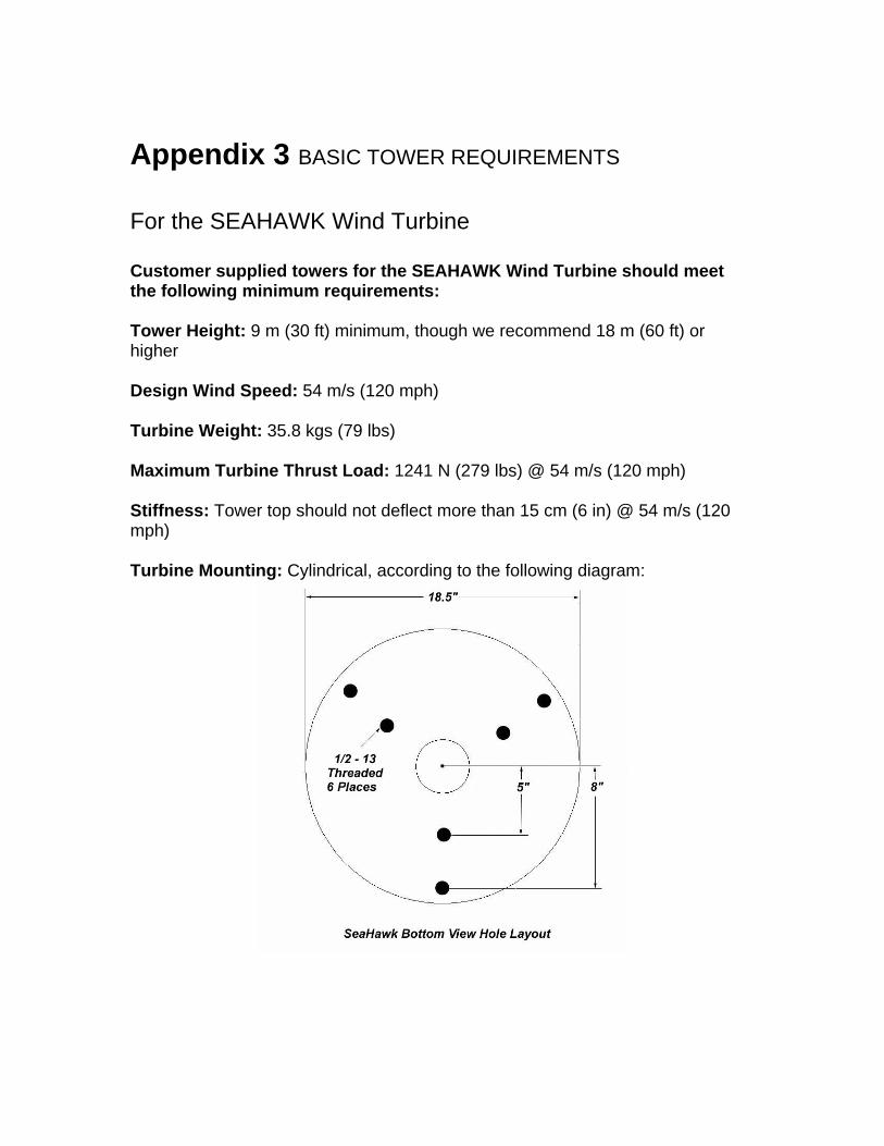
Appendix 3 BASIC TOWER REQUIREMENTS For the SEAHAWK Wind Turbine Customer supplied towers for the SEAHAWK Wind Turbine should meet the following minimum requirements: Tower Height: 9 m (30 ft) minimum, though we recommend 18 m (60 ft) or higher Design Wind Speed: 54 m/s (120 mph) Turbine Weight: 35.8 kgs (79 lbs) Maximum Turbine Thrust Load: 1241 N (279 lbs) @ 54 m/s (120 mph) Stiffness: Tower top should not deflect more than 15 cm (6 in) @ 54 m/s (120 mph) Turbine Mounting: Cylindrical, according to the following diagram:

Materials: We recommend low-carbon steel towers, with careful attention given to weld quality. Stress risers and brittle materials must be avoided because of the possibility of fatigue and cracking. We do not recommend aluminum be used due to the risk of cracking. Fasteners should be U.S. Grade 2 or Grade 5 or equivalent. Finish: We recommend hot-dip galvanizing after fabrication

Appendix 4 DISCLAIMER AND LIMITED WARRANTY LIMITED PRODUCT WARRANTY STATEMENT Limited Product Warranty. PacWind, Inc. (“PacWind”) warrants to the end-user customer (“Customer”) that each SeaHawk Vertical Axis Wind Turbine (“Product”) shall be free from defects in workmanship and materials for a period of sixty months from the date of the purchase by the Customer. PacWind’s Limited Product Warranty covers only those defects which arise as a result of normal use of the Product, and does not cover any other problems, including those which arise as a result of (a) abuse, damage, alteration, or misuse by someone other than PacWind; (b) improper maintenance or modification; (b) accessories or supplies not provided or supported by PacWind; or (d) operation outside the Product’s specifications. A Product will be considered to be free from defects in workmanship if it was manufactured in accordance with PacWind’s manufacturing workmanship standards and conforms to the Specifications and Quality Requirements for the Product. Repair or Replacement under Product Warranty. If PacWind breaches this Limited Product Warranty, the Customer may return the defective unit to PacWind through the Distributor or Dealer from whom the Product was purchased for prompt repair or for replacement with a functionally equivalent replacement unit, at PacWind’s option. PacWind will promptly repair or replace such unit at PacWind’s expense and deliver the repaired or replaced unit to the Customer through the Distributor or Dealer. The repaired or replaced Product will carry the same Product Warranty for the balance of the original warranty period. Any replacement product may be either new or like-new, provided that it has functionality at least equal to that of the Product being replaced. If PacWind is unable to repair or replace a defective Product which is covered by PacWind’s Limited Product Warranty, PacWind shall, within a reasonable time after being notified of the defect, refund the purchase price for the Product to the Customer. Limitation of Warranty and Disclaimers. All claims for breach of this Limited Product Warranty must be received before the expiration of the warranty period; THE WARRANTIES HEREIN ARE THE ONLY WARRANTIES GIVEN BY PACWIND. PACWIND MAKES NO OTHER WARRANTY EITHER EXPRESS OR IMPLIED. ALL WARRANTIES OF MERCHANTABILITY, SATISFACTORY QUALITY, OR FITNESS FOR A PARTICULAR PURPOSE OR USE ARE EXPRRESSLY DISCLAIMED AND EXCLUDED.

THE REMEDIES PROVIDED IN THIS LIMITED PRODUCT WARRANTY STATEMENT ARE THE CUSTOMER’S SOLE AND EXCLUSIVE REMEDIES. EXCEPT FOR THE OBLIGATIONS SPECIFICALLY SET FORTH IN THIS LIMITED PRODUCT WARRANTY STATEMENT, IN NO EVENT SHALL PACWIND OR ITS THIRD PARTY SUPPLIERS BE LIABLE FOR DIRECT, INDIRECT, SPECIAL, INCIDENTIAL, OR CONSEQUENTIAL DAMAGES, WHETHER BASED ON CONTRACT, TORT, OR ANY OTHER LEGAL THEORY AND WHETHER ADVISED OF THE POSSIBILITY OF SUCH DAMAGES, INCLUDING, WITHOUT LIMITATION, LOST PROFITS, COSTS OF DELAY, ANY FAILURE OF DELIVERY, OR LIABILITIES TO THIRD PARTIES ARISING FROM ANY SOURCE. This Limited Product Warranty Statement gives the Customer specific legal rights. The Customer may also have other rights which vary from state to state in the United States, from province to province in Canada, and from country/region to country/region elsewhere in the world. To the extent this Limited Product Warranty Statement is inconsistent with local law, this Statement shall be deemed modified to be consistent with such local law. Under such local law, certain disclaimers and limitations of this Statement may not apply to the Customer.