sea-trial of optical ethernet modems for underwater
TRANSCRIPT
JOURNAL OF LIGHTWAVE TECHNOLOGY, VOL. 36, NO. 23, DECEMBER 1, 2018 5371
Sea-Trial of Optical Ethernet Modems forUnderwater Wireless Communications
Giulio Cossu , Alessandro Sturniolo, Alessandro Messa, Simone Grechi, Daniele Costa , Andrea Bartolini,David Scaradozzi, Andrea Caiti, Fellow, IEEE, and Ernesto Ciaramella , Senior Member, IEEE
Abstract—A new pair of optical wireless modems has been re-alized, which exploit visible light communication to transmit Eth-ernet signals through water. The modem prototypes were finallytested in sea waters at La Spezia harbor; they successfully trans-mitted 10 Mbit/s 10Base-T signals over up to 10 m, notwithstandingthe high turbidity and the strong sunlight. Final tests included theintegration with SUNRISE testbed and the use with a moving robot,remotely operated. Commercial components were used to realizethe modems; thus, we expect that the key design concepts can beused as a starting point for practical deployment of this technology.
Index Terms—Light emitting diodes, underwater communica-tion, visible light communication, wireless communication.
I. INTRODUCTION
W IRELESS data transmission usually relies on electro-magnetic waves in the radio-frequency (RF) part of the
spectrum. However, the underwater environment represents arelevant exception, since water strongly attenuates RF waves[1]–[4]. Submarine exploration and monitoring is now being ex-tended to greater regions and depths, thanks to the developmentof autonomous underwater vehicles (AUVs) [5], which allowfor an increasing number of tasks. AUVs, however, need com-munication means to transmit the conveyed information at thecontrol stations on land or ships: although wired transmissionmight be feasible, wireless communication is by far more practi-cal. However, since RF cannot be exploited, today the submarinecommunications mostly rely on acoustic waves [6]. Unfortu-nately, only low-frequency acoustic waves exhibit low attenu-ation [7], high-frequency waves suffer from strong absorptionand mechanical limitations. This strongly limits the availablebandwidth of common acoustic modems around few kHz andhence their bit rate [8]: high-performance acoustic modems can
Manuscript received May 15, 2018; revised September 12, 2018; acceptedSeptember 15, 2018. Date of publication September 19, 2018; date of currentversion November 2, 2018. This work was supported in part by the EuropeanUnion, ICT FP7 funding scheme, Project “SUNRISE,” under Grant 611449.(Corresponding author: Ernesto Ciaramella.)
G. Cossu, A. Sturniolo, A. Messa, and E. Ciaramella are with ScuolaSuperiore Sant’Anna University, 56124 Pisa, Italy (e-mail:, [email protected]).
A. Bartolini, D. Costa, and D. Scaradozzi are with Universita Politecnicadelle Marche, 60131 Ancona, Italy.
S. Grechi is with University of Pisa, 56122 Pisa, Italy, and also with HondaRacing F1, Milton Keynes, MK61BD, U.K.
A. Caiti is with University of Pisa, 56122 Pisa, Italy.Color versions of one or more of the figures in this paper are available online
at http://ieeexplore.ieee.org.Digital Object Identifier 10.1109/JLT.2018.2871088
reach 35 kbit/s [9], but common products have a typical rateof few kbit/s [10]. Moreover, the above rates are achieved inoptimal channel conditions: the strong variability of the un-derwater acoustical communication channel, due to the varyingoceanographic conditions, strongly degrades in practice the per-formance of acoustic modems [11].
While mankind is actively pursuing explorations of the Moonand outer space, around 95% of the world’s oceans and 99%of the ocean floor still remain unexplored [12]. Recently, theunderwater activities are increasing, pushing the research fornovel solutions. There is a wide variety of systems deputed atsea-monitoring, ranging from buoys, ships, the aforementionedAUVs, Remotely Operated Vehicles (ROVs) [13]–[15] andUnderwater Sensor Networks (UWSNs) [16]. AUVs currentlyrepresent a well-proven technology [17]–[23]. These vehiclescan record high-resolution images, videos, sonar and other data,and transmit them to a central unit or a backbone, withoutresurfacing, even in very shallow water or even in harbor en-vironment. For this type of data, high bit rate and low latencytransmission is usually required. Due to these requirements, theunderwater systems are often forced to wired solutions, whichimpact on device mobility and re-configurability, limiting thepossible applications [24].
Combining high-speed and wireless transmission, theUnderwater Wireless Optical Communications (UWOC) is avalid alternative, which is rapidly gaining popularity. Recently,the impressive developments in Light Emitting Diodes (LEDs)for lighting purposes made widely available compact devicesof low-cost and significant modulation bandwidth. This alsoopened the way to the terrestrial (indoor) Visible Light Commu-nications (VLC), which use LEDs to transmit wireless signals.VLC recent implementations showed very high bit rates [25]–[29]; this gave momentum to the use in underwater environment,as sea-water has a low-loss window in the visible region that canbe conveniently exploited by UWOC. Thanks to this, UWOCcan offer much higher bit rates, compared to acoustic modems,although at shorter distances. Depending on bit rate and water at-tenuation, this technology can reach Mbit/s rates over tens of me-ters [30]–[33]. Both Laser Diodes (LDs) or LEDs were proposedin UWOC systems. The former have much wider bandwidth andhigher optical power, but are more expensive compared to LEDs,are prone to misalignment and may require active temperaturestabilization [34]–[36]. First LED-based UWOC systems wasable to transmit data at 5–20 Mbit/s over ranges up to 100 m in
0733-8724 © 2018 IEEE. Personal use is permitted, but republication/redistribution requires IEEE permission.See http://www.ieee.org/publications standards/publications/rights/index.html for more information.
5372 JOURNAL OF LIGHTWAVE TECHNOLOGY, VOL. 36, NO. 23, DECEMBER 1, 2018
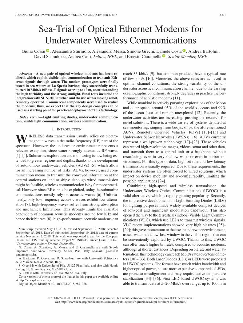
Fig. 1. The OptoCOMM scenario, where three optical modems are equippedon a AUV, on a ROV and on a buoy connected to the infrastructure.
clear, dark waters (2400 m depth) [37], [38]. Other blue-lightLED-based systems (see for instance [39], [40], and referencestherein). A product is also available [41], in two versions: oneclaimed to deliver 5 Mbit/s at 10 m range in ‘high ambient light’conditions, the other with data rate between 2.5 and 12.5 Mbit/sat ranges up to 150 m, which is claimed “suitable for moderateto low turbidity dark water (>200 m depth or night-time)”.
These achievements are quite impressive; nevertheless theyshare many limitations, in particular in very shallow water andhigh turbidity conditions. An operational environment with suchconditions is that of commercial and military harbors, whereAUV-based patrolling and surveying is actively developed [42],with the constraint of not resurfacing in order not to interferewith normal harbor operations.
In recent years, the Authors used blue LEDs and DiscreteMulti-Tone to demonstrate 58 Mb/s in 2.5 m clear water, inan outdoor pool with a waterproof transmitter (TX) and a re-ceiver (RX), both submerged [43]. The system worked understrong sunlight illumination, which usually poses a severe limi-tation to the achievable Optical Signal to Noise Ratio (OSNR).Building on this preliminary result, here we present the finaldesign and the at-sea tests of an optical communication system(OptoCOMM), oriented, but not restricted, to operations in day-light harbor conditions, i.e., in presence of both high sunlightdisturbance and high water-turbidity.
The system was realized in the framework of the EU-FP7SUNRISE project [44], and it is thus suitable for integrationin the project network of underwater things [45], [46]. The re-sults reported here show that the OptoCOMM UWOC modemsprovide a reliable 10Base-T IEEE standard bi-directional trans-mission (10 Mbit/s Ethernet) up to 10 m in very shallow harborwater and daylight condition. On the application layer side, thesystem is also fully integrated with the SUNSET software frame-work of the SUNRISE project, allowing the operation and datatransmission both from local and remotely connected workingstations (as shown in Fig. 1).
In [47], we reported the preliminary results of the early stageof the OptoCOMM development, particularly dealing with test-ing of the optical part. In this paper, the final version of themodems is described, and the performance in sea-trial tests ofthe closed system is reported in terms of packet loss, transmis-sion distance, sunlight illumination and water turbidity. A shortsummary of these tests was recently presented in [48].
This paper is organized as follows. In Section II, we describethe key limiting effects in our UWOC case. In Section III, wepresent the design of the proposed modems and the equipmentused for the demonstration. In Section IV, we report the resultsobtained in the lab to finally characterize the optical compo-nents and the system performance. In Section V, we present theresults of the sea-trials measurements performed at La Speziaharbor, namely at NATO’s Centre for Maritime Research andExperimentation (CMRE) and at the Italian Navy’s Centro diSupporto e Sperimentazione Navale (CSSN) facilities.
II. UNDERWATER COMMUNICATION CHALLENGES
In this section, we provide a summary of the main trans-mission impairments that were considered when designing themodems, i.e., the signal attenuation and the sunlight influence.
A. Optical Loss
In an UWOC link, three main effects contribute to the signalattenuation: absorption, scattering and beam divergence. Theloss coefficients due to the absorption, a(λ), and the scattering,b(λ), are usually combined in the extinction coefficient k(λ):
k (λ) = a (λ) + b (λ) . (1)
As known, water attenuation has a minimum in the visibleregion [49]. The exact wavelength of the lowest attenuation de-pends on the specific composition of the sea water and it can beaffected by the presence of biological and non-biological ele-ments. In clear and pure waters, the best propagation is attainedaround the blue-green region (∼470 nm). This value shifts to-wards longer wavelengths when the turbidity increases [50].Since our modems are designed to operate also in clear waters,we choose blue LEDs for our TX.
In UWOC, precise alignment and tracking with a movingrobot would be very hard to attain, e.g., due to water currents.Therefore, in order to have wide tolerance to misalignment werealized the system with non-negligible beam divergence. Ob-viously, in addition to scattering and absorption, optical beamdivergence also affects the final received power: from the re-ceiver point of view, it may be equivalent as a source of loss.Therefore, we can derive a simplified expression from [9] toestimate the received power (Popt) vs. the distance d, on axis
Popt (d) ∼= P1
d2 exp [−k(λ) (d − 1)] (2)
where P1 is the power received at 1 m, d is in meters. In-deed, when designing UWOC modems, one must choose thebeam divergence, which determines P1 ; a great divergence doesnot require high accuracy in the modem alignment and canmake easier to achieve the link connection. However, a highdivergence clearly limits UWOC at long ranges. In our case, thebest trade-off is obtained for the non-negligible divergence ofthe beam of around 20 degrees, which is compatible with ourtarget distance of 10 m in shallow waters.
In the real sea, the accurate loss measurement of the opticalsignal is apparently difficult; moreover, the instantaneous signalloss is also affected by strong variations due to the environment:
COSSU et al.: SEA-TRIAL OF OPTICAL ETHERNET MODEMS FOR UNDERWATER WIRELESS COMMUNICATIONS 5373
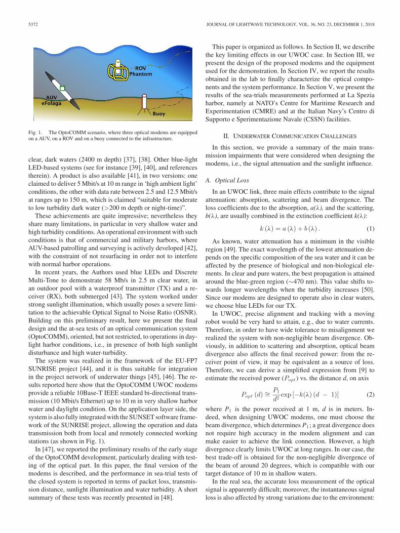
Fig. 2. Histogram of values of turbidity measured at 1 m depth.
season, weather, reflections of light at wave surface and waterturbidity may change with time, sometimes very quickly. Theyall affect the measurements, which indeed show both long-termand short-term fluctuations.
In order to measure the value of the extinction coefficient atsea, we can use two alternative methods. First, we can mea-sure Popt at different distances using the monitoring part ofthe modems (see later) and then extract P1 and k by fitting themeasurements. This technique is more accurate in principle, butmoving frequently the modems may result unpractical. Mostly,moving the modems takes some time, thus the results can be farfrom accurate when the short-term variations are very signifi-cant.
Alternatively, we can rely on measurements of the turbiditycoefficient using a turbidimeter. This second option is by farfaster and therefore more practical, although in principle givesonly indirect information. In a previous preliminary investiga-tion at the sea test site, we experimentally confirmed that k andFormazin Turbidity Unit (FTU) values are in linear relationshipwith a slope coefficient of k/FTU � 0.2 [47], [51]. Previouslyindependent experimental evidence was reported about a rela-tionship between the light penetration in water and its turbidity,indicating that typical harbor water had k ∼ 0.3 m−1 [52]. Theabove values are all related to a single measurement event. InFig. 2, we report a histogram of measured turbidity at 1 m depth,at different times, in the test site location and the same day. Ascan be expected, the channel conditions change significantly.The modems must be thus designed to work with dynamicallyvarying conditions.
B. Sunlight Influence
Testing UWOC in shallow waters, we faced another impair-ment: in our outdoor conditions, we measured an illuminancelevel in the order of 104 lux due to the sunlight [47]. We mea-sured this value as close as possible to the RX, i.e., just abovethe water surface. This measured value is much higher thanthe typical values of indoor illumination (500 lux), which arecommon in the other VLC implementations. Even assuming theeffect of a band-pass filter at RX, sunlight is so relevant thatit produces a photo-current much higher (a factor ∼102) than
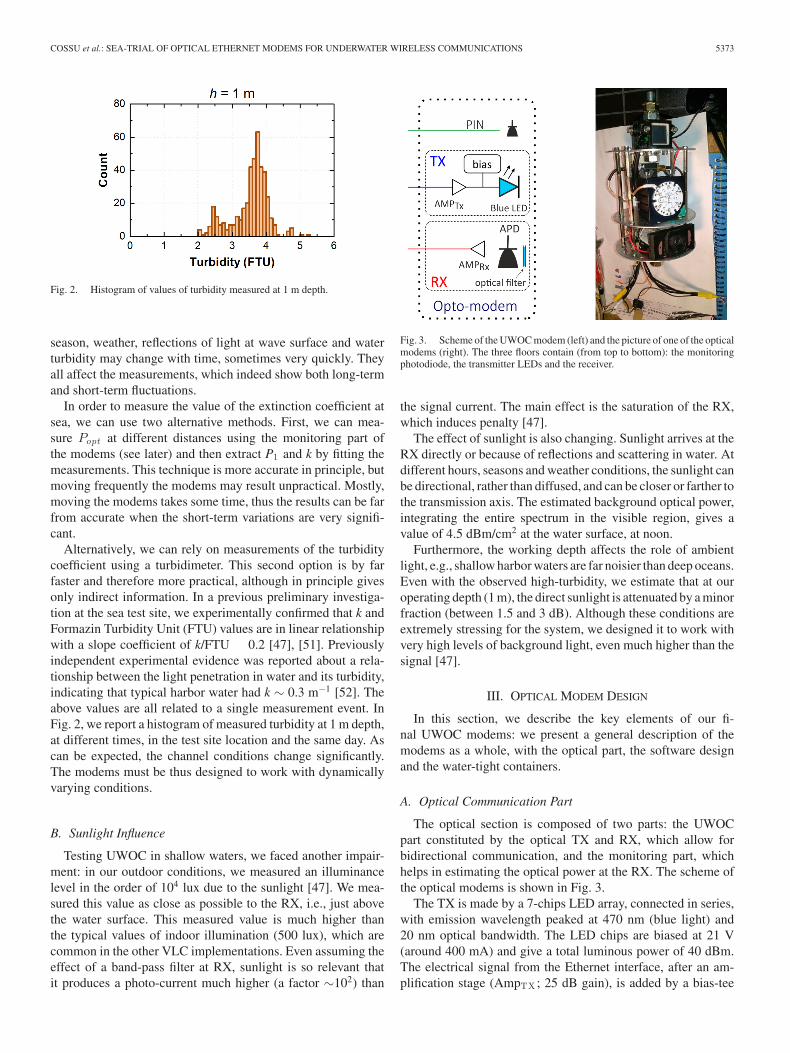
Fig. 3. Scheme of the UWOC modem (left) and the picture of one of the opticalmodems (right). The three floors contain (from top to bottom): the monitoringphotodiode, the transmitter LEDs and the receiver.
the signal current. The main effect is the saturation of the RX,which induces penalty [47].
The effect of sunlight is also changing. Sunlight arrives at theRX directly or because of reflections and scattering in water. Atdifferent hours, seasons and weather conditions, the sunlight canbe directional, rather than diffused, and can be closer or farther tothe transmission axis. The estimated background optical power,integrating the entire spectrum in the visible region, gives avalue of 4.5 dBm/cm2 at the water surface, at noon.
Furthermore, the working depth affects the role of ambientlight, e.g., shallow harbor waters are far noisier than deep oceans.Even with the observed high-turbidity, we estimate that at ouroperating depth (1 m), the direct sunlight is attenuated by a minorfraction (between 1.5 and 3 dB). Although these conditions areextremely stressing for the system, we designed it to work withvery high levels of background light, even much higher than thesignal [47].
III. OPTICAL MODEM DESIGN
In this section, we describe the key elements of our fi-nal UWOC modems: we present a general description of themodems as a whole, with the optical part, the software designand the water-tight containers.
A. Optical Communication Part
The optical section is composed of two parts: the UWOCpart constituted by the optical TX and RX, which allow forbidirectional communication, and the monitoring part, whichhelps in estimating the optical power at the RX. The scheme ofthe optical modems is shown in Fig. 3.
The TX is made by a 7-chips LED array, connected in series,with emission wavelength peaked at 470 nm (blue light) and20 nm optical bandwidth. The LED chips are biased at 21 V(around 400 mA) and give a total luminous power of 40 dBm.The electrical signal from the Ethernet interface, after an am-plification stage (AmpTX ; 25 dB gain), is added by a bias-tee
5374 JOURNAL OF LIGHTWAVE TECHNOLOGY, VOL. 36, NO. 23, DECEMBER 1, 2018
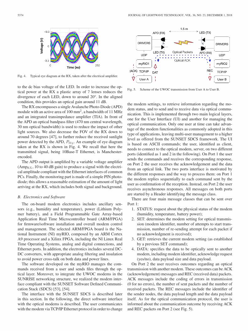
Fig. 4. Typical eye diagram at the RX, taken after the electrical amplifier.
to the dc bias voltage of the LED. In order to increase the op-tical power at the RX a plastic array of 7 lenses reduces thedivergence of each LED, down to around 20°. In the alignedcondition, this provides an optical gain around 11 dB.
The RX encompasses a single Avalanche Photo-Diode (APD)module with an active area of 100 mm2, a bandwidth of 11 MHzand an integrated transimpedance amplifier (TIA). In front ofthe APD an optical bandpass filter (470 nm central wavelength,30 nm optical bandwidth) is used to reduce the impact of otherlight sources. We also decrease the FOV of the RX down toaround 70 degrees [47], to further reduce the received sunlightpower detected by the APD, Pbkg . An example of eye diagramtaken at the RX is shown in Fig. 4. We recall that here thetransmitted signal, being 10Base-T Ethernet, is Manchester-encoded.
The APD output is amplified by a variable voltage amplifier(AmpRX , 10 to 40 dB gain) to produce a signal with the electri-cal amplitude compliant with the Ethernet interfaces of commonPCs. Finally, the monitoring part is made of a simple PIN photo-diode; this allows a reasonable estimation of the amount of lightarriving at the RX, which includes both signal and background.
B. Electronics and Software
The on-board modem electronics includes ancillary sen-sors (e.g., humidity and temperature), power (Lithium Poly-mer battery), and a Field Programmable Gate Array-basedApplication Real Time Microcontroller board (ARM/FPGA)for firmware/software installation and overall modem controland management. The selected ARM/FPGA board is the Na-tional Instrument (NI) myRIO, composed by an ARM CortexA9 processor and a Xilinx FPGA, including the NI Linux RealTime Operating Systems, analog and digital connections, andEthernet ports. In addition, the electronics includes several DC-DC converters, with appropriate analog filtering and insulationto avoid power cross-talk on both data and power lines.
The software developed on the myRIO manages the com-mands received from a user and sends files through the op-tical layer. Moreover, to integrate the UWOC modems in theSUNRISE networking structure, we realized the modem inter-face compliant with the SUNSET Software Defined Communi-cation Stack (SDCS) [53], [54].
The interface with the SUNSET SDCS is described laterin this section. In the following, the direct software interfacewith the optical modems is described. The user communicateswith the modem via TCP/IP Ethernet protocol in order to change
Fig. 5. Scheme of the UWOC transmission from User A to User B.
the modem settings, to retrieve information regarding the mo-dem status, and to send and to receive data via optical commu-nication. This is implemented through two main logical layers,one for the User Interface (UI) and another for managing theoptical communication. Only one user at time can take advan-tage of the modem functionalities as commonly adopted in thistype of applications, leaving multi-user management to a higherlevel as offered from the SUNSET SDCS framework. The UIis based on ASCII commands; the user, identified as client,needs to connect to the optical modem, server, on two differentports (identified as 1 and 2 in the following). On Port 1 the usersends the commands and receives the corresponding response,on Port 2 the user receives the acknowledgement and the datafrom an optical link. The two ports interface is motivated bythe different responses and the way to process them: on Port 1the modem replies sequentially to each command sent by theuser as confirmation of the reception. Instead, on Port 2 the userreceives asynchronous responses. All messages on both portsare started by a Header identifying the message class.
There are four main message classes that can be sent overPort 1:
1. STATUS: request about the physical status of the modem(humidity, temperature, battery power);
2. SET: determines the modem setting for optical transmis-sion (modem identifier, number of attempts to start trans-mission, number of re-sending attempt for each packet ifno acknowledgment is received);
3. GET: retrieves the current modem setting (as establishedby a previous SET command);
4. DATA: specifies the data to be optically sent to anothermodem, including modem identifier, acknowledge request(yes/no), data payload size and data payload.
On Port 2 the user receives outcomes regarding an opticaltransmission with another modem. These outcomes can be ACK(acknowledgement) messages and REC (received data) packets.ACK messages include the coding of errors in transmission(0 for no errors), the number of sent packets and the number ofreceived packets. The REC messages include the identifier ofthe sender nodes, the data payload length and the data payloaditself. As for the optical communication protocol, the user isinformed about the communication outcome by receiving ACKand REC packets on Port 2 (see Fig. 5).
COSSU et al.: SEA-TRIAL OF OPTICAL ETHERNET MODEMS FOR UNDERWATER WIRELESS COMMUNICATIONS 5375
To achieve the maximum throughput and minimize the over-head of each packet, the UWOC is based on Ethernet UserDatagram Protocol (UDP). Compared to the TCP, the UDP isnot a reliable protocol, is not connection-oriented, and does notguarantee the order of the arriving packets. Despite these miss-ing features, the UDP is the only plausible choice due to thephysical limitations imposed by the shared means of transmis-sion, the water. However, in order to enhance the reliability ofthe UDP, a custom header of fixed length was added in eachpacket and a retransmitting procedure was implemented. Theheader is chosen to minimize the overhead, but also to includethe necessary information for a successful transmission. Eachsent packet is identified and ordered by an incremental numericvalue; in addition, the header contains the total transmission sizeand the identification of the sender and receiver modems.
From a higher level integration, including networking in aUWSN with multiple nodes, a specific OptoCOMM driver forthe SUNSET SDCS system was implemented relying on theUI messages described previously. This integration includes aspecific fragmentation module to allow SUNSET SDCS to trans-mit packets with arbitrary sizes without accounting the maxi-mum packet size that a specific modem can transmit [55]. Thefragmentation module is transparent to both users and protocolstack. On the TX side, once the fragmentation module receivesa packet from the upper layer, it first checks its size. If that ex-ceeds the maximum allowed by the modem in use, it splits thedata in smaller packets (chunks) and forwards them to the lowerlayer(s) of the protocol stack. On the RX side, the fragmenta-tion module reassembles the original packet once all chunks arereceived. Laboratory testing of the SUNSET SDCS interfacewere conducted [55], exchanging from remote interfaces via aVirtual Private Network (VPN) data files of size ranging from11 MBytes to 1.5 GBytes. A similar data exchange was repeatedin the experimental test reported in the following.
C. Watertight Containers
The optical and electronic parts of each of our modems, oncecompleted, were inserted into their watertight containers. Eachcontainer is composed by an assembly of two parts: the Bodyand the Head. Both parts are composed by a cylindrical tube,enclosed between two acetyl neck flanges. The Body tube ismade from an aluminum alloy and hosts the electronics. TheHead case is a 3-mm wall tube and made from Perspex. Bothtubes are bonded to the corresponding flange necks using spe-cial sealing adhesive. The upper flange of the Head and thelower flange of the Body are closed by an acetyl blind flangeconstrained by six bolted screws. A double radial O-ring seal(NBR, 3 mm Cross-Section, 100 mm Internal Diameter) was re-alized between the blind flanges and the corresponding internalsurfaces of the necks. The upper neck flange of the Body isconnected to the lower neck flange of the Head using six boltedscrews. A double axial O-ring seal (NBR, 3 mm Cross-Section,90 mm and 105 mm Internal Diameter) was realized betweenthe contact surfaces to prevent any water leakage in the modemcase joining section.
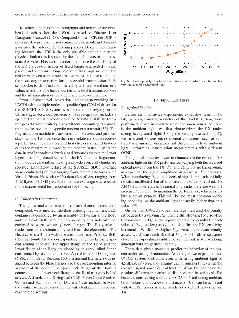
Fig. 6. Power penalty to obtain a transmission in error-free condition with avarying value of background light.
IV. FINAL LAB TESTS
A. Optical Section
Before the final at-sea experiment, exhaustive tests in thelab, spanning various parameters of the UWOC system, wereperformed. Since in shallow water the main source of noiseis the ambient light, we first characterized the RX understrong background light. Using the setup presented in [47],we simulated various environmental conditions, such as dif-ferent transmission distances and different levels of ambientlight, performing transmission measurements with differentOSNR.
The goal of these tests was to characterize the effect of theambient light on the RX performance, varying both the receivedoptical power from the TX (Ps) and Pbkg . For no background,as expected, the signal amplitude increases as Ps increases.When introducing Pbkg , the electrical signal amplitude initiallyremains unaffected, but after a saturation value is reached, theAPD saturation reduces the signal amplitude, therefore we mustincrease Ps in order to maintain the performance, which resultsinto a power penalty. This will be the most common work-ing condition, as the ambient light is usually higher than thisvalue [47].
On the final UWOC modem, we thus measured the penaltyintroduced by a varying Pbkg , while still allowing for error-freetransmission. In Fig. 6, we report the obtained penalty for eachvalue of Pbkg . As long as Pbkg < −40 dBm, the RX sensitivityis around −39 dBm. At higher Pbkg values, a relevant penaltyarises, which can reach 10 dB at Pbkg ∼ −14 dBm, i.e., quiteclose to our operating conditions. Yet, the link is still working,although with a significant penalty.
These data give a means to predict the behavior of the sys-tem under strong illumination. As example, we expect that ourUWOC system will work even with strong ambient light of4.5 dBm/cm2 (typical of a sunny day in summer time) when thereceived signal power Ps is at least –26 dBm. Depending on thek value, different transmission distances can be achieved. Forinstance, considering a value k = 0.25 m−1 and strong ambientlight background as above, a distance of 10 m can be achievedwith 40 dBm power source, which is the optical power by ourTX.
5376 JOURNAL OF LIGHTWAVE TECHNOLOGY, VOL. 36, NO. 23, DECEMBER 1, 2018
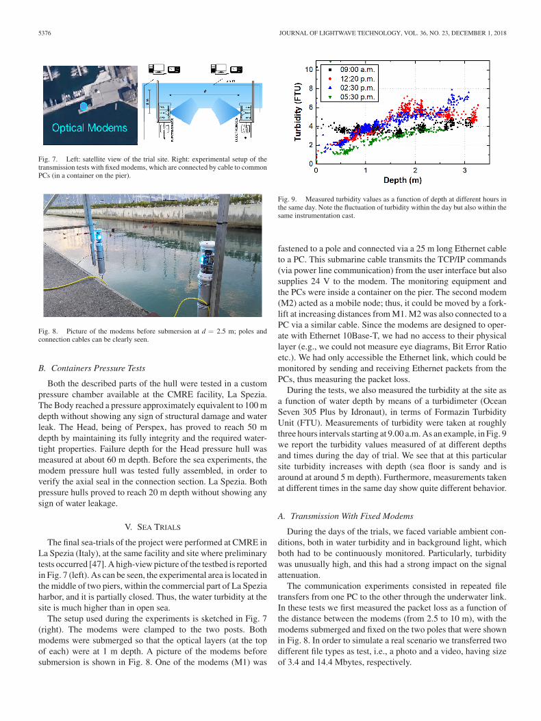
Fig. 7. Left: satellite view of the trial site. Right: experimental setup of thetransmission tests with fixed modems, which are connected by cable to commonPCs (in a container on the pier).
Fig. 8. Picture of the modems before submersion at d = 2.5 m; poles andconnection cables can be clearly seen.
B. Containers Pressure Tests
Both the described parts of the hull were tested in a custompressure chamber available at the CMRE facility, La Spezia.The Body reached a pressure approximately equivalent to 100 mdepth without showing any sign of structural damage and waterleak. The Head, being of Perspex, has proved to reach 50 mdepth by maintaining its fully integrity and the required water-tight properties. Failure depth for the Head pressure hull wasmeasured at about 60 m depth. Before the sea experiments, themodem pressure hull was tested fully assembled, in order toverify the axial seal in the connection section. La Spezia. Bothpressure hulls proved to reach 20 m depth without showing anysign of water leakage.
V. SEA TRIALS
The final sea-trials of the project were performed at CMRE inLa Spezia (Italy), at the same facility and site where preliminarytests occurred [47]. A high-view picture of the testbed is reportedin Fig. 7 (left). As can be seen, the experimental area is located inthe middle of two piers, within the commercial part of La Speziaharbor, and it is partially closed. Thus, the water turbidity at thesite is much higher than in open sea.
The setup used during the experiments is sketched in Fig. 7(right). The modems were clamped to the two posts. Bothmodems were submerged so that the optical layers (at the topof each) were at 1 m depth. A picture of the modems beforesubmersion is shown in Fig. 8. One of the modems (M1) was
Fig. 9. Measured turbidity values as a function of depth at different hours inthe same day. Note the fluctuation of turbidity within the day but also within thesame instrumentation cast.
fastened to a pole and connected via a 25 m long Ethernet cableto a PC. This submarine cable transmits the TCP/IP commands(via power line communication) from the user interface but alsosupplies 24 V to the modem. The monitoring equipment andthe PCs were inside a container on the pier. The second modem(M2) acted as a mobile node; thus, it could be moved by a fork-lift at increasing distances from M1. M2 was also connected to aPC via a similar cable. Since the modems are designed to oper-ate with Ethernet 10Base-T, we had no access to their physicallayer (e.g., we could not measure eye diagrams, Bit Error Ratioetc.). We had only accessible the Ethernet link, which could bemonitored by sending and receiving Ethernet packets from thePCs, thus measuring the packet loss.
During the tests, we also measured the turbidity at the site asa function of water depth by means of a turbidimeter (OceanSeven 305 Plus by Idronaut), in terms of Formazin TurbidityUnit (FTU). Measurements of turbidity were taken at roughlythree hours intervals starting at 9.00 a.m. As an example, in Fig. 9we report the turbidity values measured of at different depthsand times during the day of trial. We see that at this particularsite turbidity increases with depth (sea floor is sandy and isaround at around 5 m depth). Furthermore, measurements takenat different times in the same day show quite different behavior.
A. Transmission With Fixed Modems
During the days of the trials, we faced variable ambient con-ditions, both in water turbidity and in background light, whichboth had to be continuously monitored. Particularly, turbiditywas unusually high, and this had a strong impact on the signalattenuation.
The communication experiments consisted in repeated filetransfers from one PC to the other through the underwater link.In these tests we first measured the packet loss as a function ofthe distance between the modems (from 2.5 to 10 m), with themodems submerged and fixed on the two poles that were shownin Fig. 8. In order to simulate a real scenario we transferred twodifferent file types as test, i.e., a photo and a video, having sizeof 3.4 and 14.4 Mbytes, respectively.
COSSU et al.: SEA-TRIAL OF OPTICAL ETHERNET MODEMS FOR UNDERWATER WIRELESS COMMUNICATIONS 5377
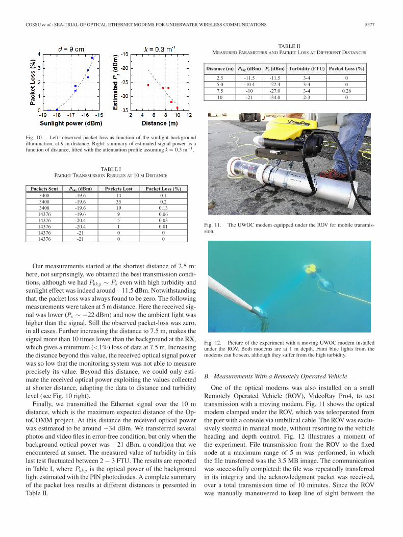
Fig. 10. Left: observed packet loss as function of the sunlight backgroundillumination, at 9 m distance. Right: summary of estimated signal power as afunction of distance, fitted with the attenuation profile assuming k = 0.3 m−1.
TABLE IPACKET TRANSMISSION RESULTS AT 10 M DISTANCE
Our measurements started at the shortest distance of 2.5 m:here, not surprisingly, we obtained the best transmission condi-tions, although we had Pbkg ∼ Ps even with high turbidity andsunlight effect was indeed around −11.5 dBm. Notwithstandingthat, the packet loss was always found to be zero. The followingmeasurements were taken at 5 m distance. Here the received sig-nal was lower (Ps ∼ −22 dBm) and now the ambient light washigher than the signal. Still the observed packet-loss was zero,in all cases. Further increasing the distance to 7.5 m, makes thesignal more than 10 times lower than the background at the RX,which gives a minimum (<1%) loss of data at 7.5 m. Increasingthe distance beyond this value, the received optical signal powerwas so low that the monitoring system was not able to measureprecisely its value. Beyond this distance, we could only esti-mate the received optical power exploiting the values collectedat shorter distance, adapting the data to distance and turbiditylevel (see Fig. 10 right).
Finally, we transmitted the Ethernet signal over the 10 mdistance, which is the maximum expected distance of the Op-toCOMM project. At this distance the received optical powerwas estimated to be around −34 dBm. We transferred severalphotos and video files in error-free condition, but only when thebackground optical power was −21 dBm, a condition that weencountered at sunset. The measured value of turbidity in thislast test fluctuated between 2 − 3 FTU. The results are reportedin Table I, where Pbkg is the optical power of the backgroundlight estimated with the PIN photodiodes. A complete summaryof the packet loss results at different distances is presented inTable II.
TABLE IIMEASURED PARAMETERS AND PACKET LOSS AT DIFFERENT DISTANCES
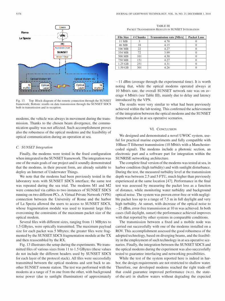
Fig. 11. The UWOC modem equipped under the ROV for mobile transmis-sion.
Fig. 12. Picture of the experiment with a moving UWOC modem installedunder the ROV. Both modems are at 1 m depth. Faint blue lights from themodems can be seen, although they suffer from the high turbidity.
B. Measurements With a Remotely Operated Vehicle
One of the optical modems was also installed on a smallRemotely Operated Vehicle (ROV), VideoRay Pro4, to testtransmission with a moving modem. Fig. 11 shows the opticalmodem clamped under the ROV, which was teleoperated fromthe pier with a console via umbilical cable. The ROV was exclu-sively steered in manual mode, without resorting to the vehicleheading and depth control. Fig. 12 illustrates a moment ofthe experiment. File transmission from the ROV to the fixednode at a maximum range of 5 m was performed, in whichthe file transferred was the 3.5 MB image. The communicationwas successfully completed: the file was repeatedly transferredin its integrity and the acknowledgment packet was received,over a total transmission time of 10 minutes. Since the ROVwas manually maneuvered to keep line of sight between the
5378 JOURNAL OF LIGHTWAVE TECHNOLOGY, VOL. 36, NO. 23, DECEMBER 1, 2018
Fig. 13. Top: Block-diagram of the remote connection through the SUNSETframework; Bottom: results on data transmission through the SUNSET SDCSboth in transmission and in reception.
modems, the vehicle was always in movement during the trans-mission. Thanks to the chosen beam divergence, the commu-nication quality was not affected. Such accomplishment provesalso the robustness of the optical modems and the feasibility ofoptical communication during an operation at sea.
C. SUNSET Integration
Finally, the modems were tested in the fixed configurationwhen integrated in the SUNSET framework. The integration wasone of the main goals of our project and it soundly demonstratedthat the modems, in their present form, are already suitable todeploy an Internet of Underwater Things.
We note that the modems had been previously tested in thelaboratory tests with SUNSET SDCS interface; the same testwas repeated during the sea trial. The modems M1 and M2were connected via cables to two instances of SUNSET SDCSrunning on two different PCs. A Virtual Private Network (VPN)connection between the University of Rome and the harborof La Spezia allowed the users to access to SUNSET SDCS,whose fragmentation module was used to transmit large filesovercoming the constraints of the maximum packet size of theoptical modem.
Several files with different sizes, ranging from 11 MBytes to1.5 GBytes, were optically transmitted. The maximum payloadsize for each packet was 5 Mbytes; the greater files were frag-mented by the SUNSET SDCS fragmentation module at the TXand then reassembled by the RX.
Fig. 13 illustrates the setup during the experiments. We trans-mitted files of various sizes from 11 to 1.5 GBytes (these valuesdo not include the different headers used by SUNSET SDCSfor each layer of the protocol stack). All files were successfullytransmitted between the optical modems and sent back to an-other SUNSET remote station. The test was performed with themodems at a range of 5 m one from the other, with backgroundnoise power (due to sunlight illumination) of approximately
TABLE IIIPACKET TRANSMISSION RESULTS IN SUNSET INTEGRATION
−11 dBm (average through the experimental time). It is worthnoting that, while the optical modems operated always at10 Mbit/s rate, the overall SUNSET network rate was on av-erage 4 Mbit/s (see Table III), mainly due to delay and latencyintroduced by the VPN.
The results were very similar to what had been previouslyachieved within the lab testing. This confirmed the achievementof the integration between the optical modems and the SUNSETframework also in at sea operative scenarios.
VI. CONCLUSION
We designed and demonstrated a novel UWOC system, use-ful for practical marine experiments and fully compatible with10Base-T Ethernet transmission (10 Mbit/s with a Manchester-coded signal). The modems include a photonic section, anelectronic part and a software part for integration within theSUNRISE networking architecture.
The complete final version of the modems was tested at sea, inharbor condition (high turbidity) and with sunlight disturbance.During the test, the measured turbidity level at the transmissiondepth was between 2.5 and 5 FTU, much higher than previouslyexperienced at the same location [47]. Performance in the finaltest was assessed by measuring the packet loss as a functionof distance, while monitoring water turbidity and backgroundoptical noise. The system was proven error-free or with negligi-ble packet loss up to a range of 7.5 m in full daylight and veryhigh turbidity. At sunset, with decrease of the optical noise to−21 dBm, error-free transmission at 10 m was achieved. In bothcases (full daylight, sunset) the performance achieved improveswith that reported by other systems in comparable conditions.
The transmission between a fixed and a mobile node wascarried out successfully with one of the modems installed on aROV. This accomplishment assessed the good robustness of theadopted technology, based on diverging beams, and the feasibil-ity in the employment of such technology in at sea operative sce-narios. Finally, the integration between the SUNSET SDCS andthe optical modems during the experiment was also successfullytested to guarantee interfacing and networking possibilities.
While the test of the system reported here is indeed in har-bor, the design requirements are not restricted to shallow water.Therefore, our developed modems reached the right trade-offthat could guarantee improved performance (w.r.t. the state-of-the-art) in shallow waters without degrading the expected
COSSU et al.: SEA-TRIAL OF OPTICAL ETHERNET MODEMS FOR UNDERWATER WIRELESS COMMUNICATIONS 5379
performance in deep, dark and clear waters. While open sea,deep-water transmission was not tested, the laboratory calibra-tions and the estimated relation between turbidity and extinctioncoefficient allow to predict an achievable transmission range ofat least 40 m in deep, dark waters.
ACKNOWLEDGMENT
The authors gratefully acknowledge the personnel of CMREand of Naval Support and Experimentation Centre of ItalianNavy (CSSN) for their support during the experiments, mostlythe technical support from P. Guerrini and J. Alves.
REFERENCES
[1] S. Sendra, J. V. Lamparero, J. Lloret, and M. Ardid, “Study of the opti-mum frequency at 2.4 GHz ISM band for underwater wireless Ad Hoccommunications,” in Ad-Hoc, Mobile, and Wireless Networks. ADHOC-NOW 2012. (Lecture Notes in Computer Science, vol. 7363), X.-Y. Li, S.Papavassiliou, and S. Ruehrup, Eds. Berlin, Germany: Springer, 2012,pp. 260–273.
[2] S. I. Inacio et al., “Dipole antenna for underwater radio communications,”in Proc. IEEE 3rd Underwater Commun. Netw. Conf., 2016, pp. 1–5.
[3] E. Jimenez et al., “Investigation on radio wave propagation in shallowseawater: Simulations and measurements,” in Proc. 3rd Underwater Com-mun. Netw. Conf., 2016, pp. 1–5.
[4] U. M. Qureshi et al., “RF path and absorption loss estimation for under-water wireless sensor networks in different water environments,” Sensors,vol. 16, no. 6, p. 890, Jun. 2016.
[5] D. Scaradozzi et al., “BCF swimming locomotion for autonomous un-derwater robots: A review and a novel solution to improve control andefficiency,” Ocean Eng., vol. 130, pp. 437–453, 2017.
[6] J. H. Cui, J. Kong, M. Gerla, and S. Zhou, “The challenges of buildingscalable mobile underwater wireless sensor networks for aquatic applica-tions,” IEEE Network, vol. 20, no. 3, pp. 12–18, May/Jun. 2006.
[7] P. G. Sasi, B. Rao, and S. Member, “Path loss analysis of underwater com-munication systems,” in Proc. IEEE Technol. Students’ Symp., Jan. 2011,pp. 65–70.
[8] B. Li et al., “Further results on high-rate MIMO-OFDM underwater acous-tic communications,” in Proc. OCEANS, 2008, pp. 1–6.
[9] H. Kaushal and G. Kaddoum, “Underwater optical wireless communica-tion,” IEEE Access, vol. 4, pp. 1518–1547, 2016.
[10] S. Sendra, J. Lloret, J. M. Jimenez, and L. Parra, “Underwater acousticmodems,” IEEE Sensors J., vol. 16, no. 11, pp. 4063–4071, Jun. 2016.
[11] A. Caiti, E. Crisostomi, and A. Munafo, “Physical characterization ofacoustic communication channel properties in underwater mobile sensornetworks,” in Sensor Systems and Software. S-CUBE 2009. (Lecture Notesof the Institute for Computer Sciences, Social Informatics and Telecom-munications Engineering, vol. 24), S. Hailes, S. Sicari, and G. Roussos,Eds. Berlin, Germany: Springer, 2010, pp. 111–126.
[12] O. S. Board and N. R. Council, Exploration of the Seas: Voyage Into theUnknown. Washington, DC, USA: National Academies Press, 2003.
[13] L. Sorbi, D. Scaradozzi, F. Zoppini, S. Zingaretti, and P. Gambogi,“Robotic tools and techniques for improving research in an underwaterdelicate environment,” Marine Technol. Soc. J., vol. 49, no. 5, pp. 6–17,2015.
[14] D. Scaradozzi, G. Conte, and L. Sorbi, “Assisted guidance system for Mi-cro ROV in underwater data gathering missions,” in Proc. 20th Mediter-ranean Conf. Control Automat., 2012, pp. 1373–1378.
[15] G. Conte, D. Scaradozzi, L. Sorbi, L. Panebianco, and D. Mannocchi,“ROS multi-agent structure for autonomous surface vehicles,” in Proc.OCEANS Genova, 2015, pp. 1–6.
[16] K. Alam, T. Ray, and S. G. Anavatti, “A brief taxonomy of autonomousunderwater vehicle design literature,” Ocean Eng., vol. 88, pp. 627–630,2014.
[17] D. Scaradozzi et al., “Innovative technology for studying growth areasof Posidonia oceanica,” in Proc. IEEE Workshop Environmental, Energy,Structural Monit. Syst., 2009, pp. 71–75.
[18] S.-K. Jeong et al., “Design and control of high speed unmanned under-water glider,” Int. J. Precision Eng. Manuf.-Green Technol., vol. 3, no. 3,pp. 273–279, Jul. 2016.
[19] T. Battista et al., “A dynamic model for underwater vehicle maneuveringnear a free surface,” IFAC-PapersOnLine, vol. 49, no. 23, pp. 68–73,Jan. 2016.
[20] M. Kojima et al., “AUV IRSAS for submarine hydrothermal depositsexploration,” in Proc. IEEE/OES Auton. Underwater Vehicles, 2016,pp. 161–164.
[21] S. D. Ling et al., “Stereo-imaging AUV detects trends in sea urchin abun-dance on deep overgrazed reefs,” Limnology Oceanogr., Methods, vol. 14,no. 5, pp. 293–304, May 2016.
[22] A. Munafo et al., “Autonomous underwater vehicle teams for adaptiveocean sampling: A data-driven approach,” Ocean Dyn., vol. 61, no. 11,pp. 1981–1994, Nov. 2011.
[23] T. B. Curtin and J. G. Bellingham, “Progress toward autonomous oceansampling networks,” Deep-Sea Res. Part II: Topical Studies Oceanogr.,vol. 56, no. 3–5, pp. 62–67, Feb. 2009.
[24] D. Scaradozzi, L. Sorbi, F. Zoppini, D. Scaradozzi, and P. Gambogi, “Toolsand techniques for underwater archaeological sites documentation,” inProc. OCEANS San Diego, 2013, pp. 1–6.
[25] S. Arnon, “Underwater optical wireless communication network,” Opt.Eng., vol. 49, no. 1, pp. 15001–15006, 2010.
[26] G. Cossu, R. Corsini, and E. Ciaramella, “High-speed Bi-directional opti-cal wireless system in non-directed line-of-sight configuration,” J. Lightw.Technol., vol. 32, no. 10, pp. 2035–2040, May 2014.
[27] G. Cossu, A. Wajahat, R. Corsini, and E. Ciaramella, “5.6 Gbit/s downlinkand 1.5 Gbit/s uplink optical wireless transmission at indoor distances(�1.5 m),” in Proc. Eur. Conf. Opt. Commun., 2014, pp. 1–3.
[28] V. Jungnickel et al., “A European view on the next generation optical wire-less communication standard,” in Proc. IEEE Conf. Standards Commun.Netw., 2015, pp. 106–111.
[29] M. Uysal, C. Capsoni, Z. Ghassemlooy, A. Boucouvalas, and E. Udvary,Eds. Optical Wireless Communications: An Emerging Technology. Basel,Switzerland: Springer, 2016.
[30] J. W. Giles and I. N. Bankman, “Underwater optical communicationssystems. Part 2: Basic design considerations,” in Proc. IEEE MilitaryCommun. Conf., 2005, pp. 1700–1705.
[31] A. C. Boucouvalas, K. P. Peppas, K. Yiannopoulos, and Z.Ghassemlooy, “Underwater optical wireless communications with opticalamplification and spatial diversity,” IEEE Photon. Technol. Lett., vol. 28,no. 22, pp. 2613–2616, Nov. 2016.
[32] B. M. Cochenour, L. J. Mullen, and A. E. Laux, “Characterization of thebeam-spread function for underwater wireless optical communicationslinks,” IEEE J. Ocean. Eng., vol. 33, no. 4, pp. 513–521, Oct. 2008.
[33] S. Tang, Y. Dong, and X. Zhang, “Impulse response modeling for un-derwater wireless optical communication links,” IEEE Trans. Commun.,vol. 62, no. 1, pp. 226–234, Jan. 2014.
[34] K. Nakamura, I. Mizukoshi, and M. Hanawa, “Optical wireless trans-mission of 405 nm, 145 Gbit/s optical IM/DD-OFDM signals through a48 m underwater channel,” Opt. Express, vol. 23, no. 2, pp. 1558–1566,Jan. 2015.
[35] H. M. Oubei et al., “4.8 Gbit/s 16-QAM-OFDM transmission based oncompact 450-nm laser for underwater wireless optical communication,”Opt. Express, vol. 23, no. 18, pp. 23302–23309, Sep. 2015.
[36] A. S. Fletcher et al., “A narrow-beam undersea laser communications fielddemonstration,” in Proc. OCEANS MTS/IEEE Monterey, 2016, pp. 1–5.
[37] N. Farr et al., “Optical modem technology for seafloor observatories,” inProc. OCEANS, 2006, pp. 1–6.
[38] C. Pontbriand et al., “Wireless data harvesting using the AUV Sen-try and WHOI optical modem,” Proc. OCEANS MTS/IEEE Washington,Oct. 2015, pp. 1–6.
[39] J. Xu et al., “OFDM-based broadband underwater wireless optical com-munication system using a compact blue LED,” Opt. Commun., vol. 369,pp. 100–105, Jun. 2016.
[40] P. Leon et al., “A new underwater optical modem based on highlysensitive silicon photomultipliers,” in Proc. OCEANS Aberdeen, 2017,pp. 1–6.
[41] Sonardyne. BlueComm Underwater Optical Communication. Accessed:Mar. 12, 2017. [Online]. Available: https://www.sonardyne.com/product/bluecomm-underwater-optical-communication-system
[42] S. Reed, J. Wood, and C. Haworth, “The detection and disposal of IEDdevices within harbor regions using AUVs, smart ROVs and data pro-cessing/fusion technology,” in Proc. Int. WaterSide Secur. Conf., 2010,pp. 1–7.
[43] G. Cossu et al., “Experimental demonstration of high speed underwatervisible light communications,” in Proc. 2nd Int. Workshop Opt. WirelessCommun., 2013, pp. 11–15.
5380 JOURNAL OF LIGHTWAVE TECHNOLOGY, VOL. 36, NO. 23, DECEMBER 1, 2018
[44] SUNRISE, Accessed: Jan. 1, 2017. [Online]. Available: http://www.fp7-sunrise.eu/
[45] A. Caiti et al., “OptoCOMM: Introducing a new optical underwater wire-less communication modem,” in Proc. IEEE 3rd Underwater Commun.Netw. Conf., Aug. 2016, pp. 2–6.
[46] A. Bartolini et al., “OptoCOMM: Development and experimentation of anew optical wireless underwater modem,” in Proc. OCEANS MTS/IEEEMonterey, 2016, pp. 1–5.
[47] G. Cossu, A. Sturniolo, A. Messa, D. Scaradozzi, and E. Ciaramella,“Full-fledged 10Base-T ethernet underwater optical wireless communica-tion system,” IEEE J. Sel. Areas Commun., vol. 36, no. 1, pp. 194–202,Jan. 2018.
[48] G. Cossu et al., “Sea-trial of an ethernet-based underwater VLC com-munication system,” in Proc. Opt. Fiber Commun. Conf. Expo., 2018,pp. 1–3.
[49] S. Q. Duntley, “Light in the sea,” J. Opt. Soc. Amer., vol. 53, no. 2,pp. 214–233, Feb. 1963.
[50] N. G. Jerlov, Marine Optics, vol. 14. Amsterdam, The Netherlands: Else-vier, 1976.
[51] L. Ulrik and K. Bundgaard, “Studies of the relationship between suspendedsediment concentration and light attenuation,” in Proc. Int. Conf. CohesiveTransport Processes, Leuven, Belgium, 2015, pp. 77–78.
[52] W. A. Swenson, “Influence of turbidity on fish abundance in westernLake Superior,” Office of Research and Development, U.S. EnvironmentalResearch Lab., Duluth, MN, USA, Rep. EPA/600/3-78/067, 1978.
[53] C. Petrioli et al., “The SUNSET framework for simulation, emulation andat-sea testing of underwater wireless sensor networks,” Ad Hoc Netw.,vol. 34, pp. 224–238, Nov. 2015.
[54] V. Di Valerio, F. Lo Presti, C. Petrioli, L. Picari, and D. Spaccini, “Aself-adaptive protocol stack for underwater wireless sensor networks,” inProc. OCEANS Shanghai, 2016, pp. 1–8.
[55] A. Caiti et al., “OptoCOMM and SUNSET to enable large data offloadingin underwater wireless sensor networks,” in Proc. OCEANS MTS/IEEEMonterey, 2016, pp. 1–5.
Authors’ biographies not available at the time of publication.