se06: in-sight explorer new tools for defect detection - hands on lab … expo... · ·...
TRANSCRIPT

SE06: In-Sight Explorer – New Tools for Defect
Detection - Hands On Lab
Werner Solution Expo April 8 & 9

1 Werner Solution Expo SE06: Cognex In-Sight Explorer – New Tools for Defect Detection
Learning Goals:
At the end of this lab, the student should have familiarity with the most common settings needed to
optimize the defect detection tools from Cognex. These tools are Surface Flaw Detection, Flexible Flaw
Detection, and Edge Pair tool.
Required Lab Hardware:
Laptop Running Cognex Training Virtual Machine
Required Software:
The following items are pre-installed on the Cognex Training Virtual Machine:
In-Sight Explorer Version 4.9.3
Samples Job Files and Images.
Instructions:
There are three lab exercises in this lab manual. Work through all three exercises at your own pace. Feel
free to experiment; these PCs are set up so that at the end of each session, all changes you make can be
erased.

2 Werner Solution Expo SE06: Cognex In-Sight Explorer – New Tools for Defect Detection
Getting Started:
The computer in front of you should be running the Cognex Training Virtual Machine, which looks like this:
If it is not, please ask your instructor for assistance.
Start the In-Sight Explorer Software, as shown here…

3 Werner Solution Expo SE06: Cognex In-Sight Explorer – New Tools for Defect Detection
Note: There is another software tool called Cognex Explorer, please use In-Sight Explorer 4.9.3 for this
exercise.
4 Werner Solution Expo SE06: Cognex In-Sight Explorer – New Tools for Defect Detection
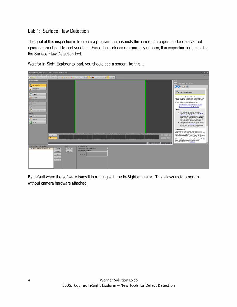
Lab 1: Surface Flaw Detection
The goal of this inspection is to create a program that inspects the inside of a paper cup for defects, but
ignores normal part-to-part variation. Since the surfaces are normally uniform, this inspection lends itself to
the Surface Flaw Detection tool.
Wait for In-Sight Explorer to load, you should see a screen like this…
By default when the software loads it is running with the In-Sight emulator. This allows us to program
without camera hardware attached.

5 Werner Solution Expo SE06: Cognex In-Sight Explorer – New Tools for Defect Detection
Step A: Load Lab 1 Images into In-Sight Emulator.
Click on Image / Record Playback Options, here…

6 Werner Solution Expo SE06: Cognex In-Sight Explorer – New Tools for Defect Detection
The following dialog box appears…
Click the “…” button to change directories to the folder containing the images for Lab 1.
7 Werner Solution Expo SE06: Cognex In-Sight Explorer – New Tools for Defect Detection
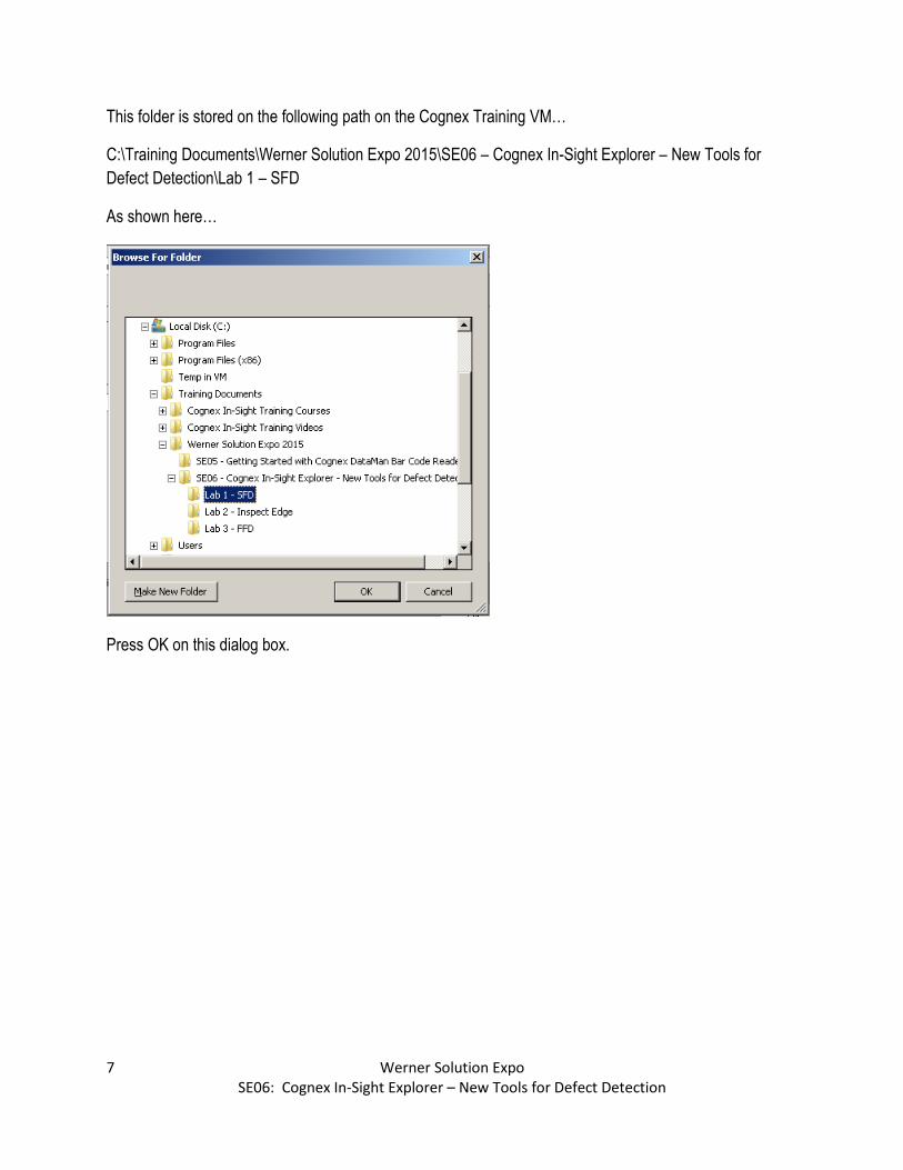
This folder is stored on the following path on the Cognex Training VM…
C:\Training Documents\Werner Solution Expo 2015\SE06 – Cognex In-Sight Explorer – New Tools for
Defect Detection\Lab 1 – SFD
As shown here…
Press OK on this dialog box.
8 Werner Solution Expo SE06: Cognex In-Sight Explorer – New Tools for Defect Detection
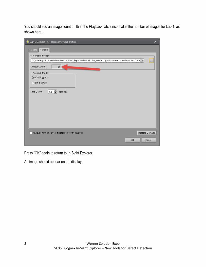
You should see an image count of 15 in the Playback tab, since that is the number of images for Lab 1, as
shown here…
Press “OK” again to return to In-Sight Explorer.
An image should appear on the display.

9 Werner Solution Expo SE06: Cognex In-Sight Explorer – New Tools for Defect Detection
Click the “PC” Button on the filmstrip control at the bottom of the image to see all of the images in the
filmstrip below the image.
The filmstrip controls are available to the right of the image filmstrip. Forward and back buttons move
through one image at a time, and the fast forward and reverse buttons move the filmstrip too the first and
last image in the filmstrip.
You can click on various images on the filmstrip to see the software advance through them all, but for the
first steps of our testing, it is critical that we set up on a good part.
The first image in the set is a good part. Make sure the first image is selected before you move on.

10 Werner Solution Expo SE06: Cognex In-Sight Explorer – New Tools for Defect Detection
Step B: Add a Locator Tool
1. Click on “Locate Part” from the top left Application Steps
2. Choose “PatMax Pattern” from the Location Tools Menu on the bottom left side.
3. Choose the “Add” button.

11 Werner Solution Expo SE06: Cognex In-Sight Explorer – New Tools for Defect Detection
The following square regions will appear on the image…
From the “Model” menu, pick Circle.
Use the mouse to move the circle to completely surround the bottom of the cup and go up the sides a bit.
To move the region you need to grab inside the region. To resize, you need to grab the edges of the
region.

12 Werner Solution Expo SE06: Cognex In-Sight Explorer – New Tools for Defect Detection
Your image should look something like this…
Then, press OK.

13 Werner Solution Expo SE06: Cognex In-Sight Explorer – New Tools for Defect Detection
The model area will highlight the edges around the bottom of the cup, like this…
14 Werner Solution Expo SE06: Cognex In-Sight Explorer – New Tools for Defect Detection
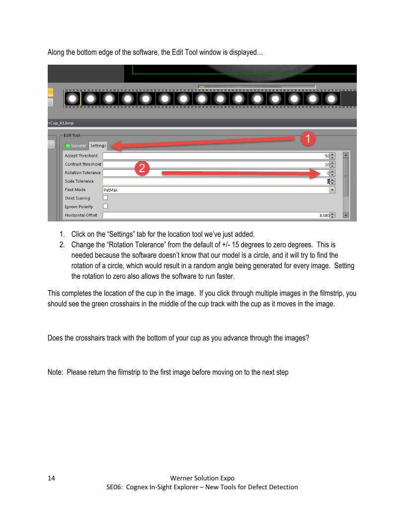
Along the bottom edge of the software, the Edit Tool window is displayed…
1. Click on the “Settings” tab for the location tool we’ve just added.
2. Change the “Rotation Tolerance” from the default of +/- 15 degrees to zero degrees. This is
needed because the software doesn’t know that our model is a circle, and it will try to find the
rotation of a circle, which would result in a random angle being generated for every image. Setting
the rotation to zero also allows the software to run faster.
This completes the location of the cup in the image. If you click through multiple images in the filmstrip, you
should see the green crosshairs in the middle of the cup track with the cup as it moves in the image.
Does the crosshairs track with the bottom of your cup as you advance through the images?
Note: Please return the filmstrip to the first image before moving on to the next step

15 Werner Solution Expo SE06: Cognex In-Sight Explorer – New Tools for Defect Detection
Step C: Add the Surface Flaw Defect Detection Tool for the Bottom of the Cup
Move to the next Application Step…
1. Click on “Inspect Part” on the Application Steps menu
2. Click the Arrow next to “Defect Detection Tools” in order to open up the menu of defect detection
tools
3. Click on “Surface Flaw” to select that tools
4. Click on “Add” to add a new Surface Flaw tool to the program

16 Werner Solution Expo SE06: Cognex In-Sight Explorer – New Tools for Defect Detection
Again, the software will default to a square Region of Interest…
1. Click on the “Region Type” menu at the bottom of the screen
2. Choose “Circle” as the region type.

17 Werner Solution Expo SE06: Cognex In-Sight Explorer – New Tools for Defect Detection
Manually move the circle ROI around the bottom of the cup. Because the Surface Flaw Detection tool is
designed to find contrast changes, and the joint between the side wall of the cup and the bottom of the cup
has a large contrast change, it is important that we avoid inspecting in that area. See how this tool is
positioned…
Once your circle is positioned, press the OK button…
18 Werner Solution Expo SE06: Cognex In-Sight Explorer – New Tools for Defect Detection
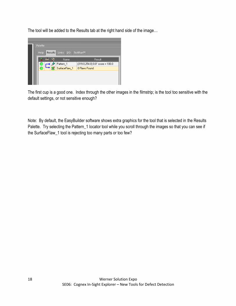
The tool will be added to the Results tab at the right hand side of the image…
The first cup is a good one. Index through the other images in the filmstrip; is the tool too sensitive with the
default settings, or not sensitive enough?
Note: By default, the EasyBuilder software shows extra graphics for the tool that is selected in the Results
Palette. Try selecting the Pattern_1 locator tool while you scroll through the images so that you can see if
the SurfaceFlaw_1 tool is rejecting too many parts or too few?
19 Werner Solution Expo SE06: Cognex In-Sight Explorer – New Tools for Defect Detection
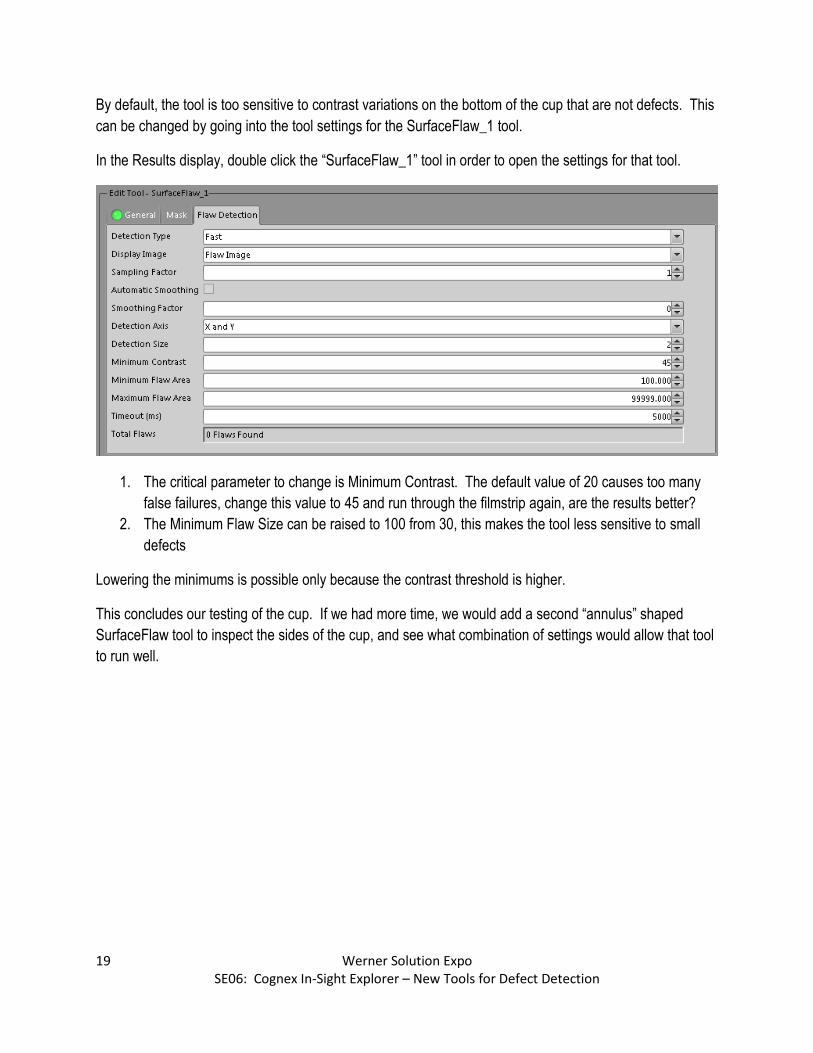
By default, the tool is too sensitive to contrast variations on the bottom of the cup that are not defects. This
can be changed by going into the tool settings for the SurfaceFlaw_1 tool.
In the Results display, double click the “SurfaceFlaw_1” tool in order to open the settings for that tool.
1. The critical parameter to change is Minimum Contrast. The default value of 20 causes too many
false failures, change this value to 45 and run through the filmstrip again, are the results better?
2. The Minimum Flaw Size can be raised to 100 from 30, this makes the tool less sensitive to small
defects
Lowering the minimums is possible only because the contrast threshold is higher.
This concludes our testing of the cup. If we had more time, we would add a second “annulus” shaped
SurfaceFlaw tool to inspect the sides of the cup, and see what combination of settings would allow that tool
to run well.
20 Werner Solution Expo SE06: Cognex In-Sight Explorer – New Tools for Defect Detection
Lab 2: Inspect Edge
The Inspect Edge tool can find defects around the edges of parts where normal defect detection tools
cannot operate. In this example, we will inspect solar panels for cracks and chips along the outside edges
of the part.
Step A: Load Images and Create a New Job File.
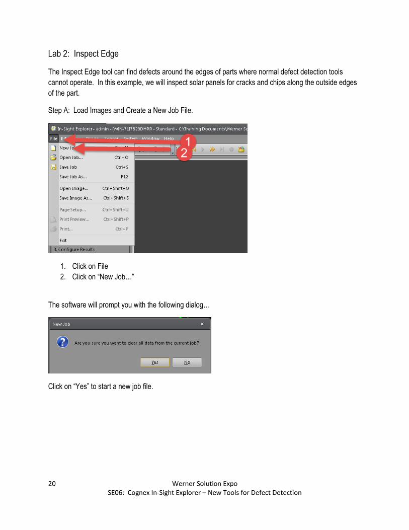
1. Click on File
2. Click on “New Job…”
The software will prompt you with the following dialog…
Click on “Yes” to start a new job file.

21 Werner Solution Expo SE06: Cognex In-Sight Explorer – New Tools for Defect Detection
Click on Image / Record Playback Options, here…
1. Click on Image
2. Click on Record / Playback Options…

22 Werner Solution Expo SE06: Cognex In-Sight Explorer – New Tools for Defect Detection
The following dialog box appears…
Click the “…” button to change directories to the folder containing the images for Lab 2.
23 Werner Solution Expo SE06: Cognex In-Sight Explorer – New Tools for Defect Detection
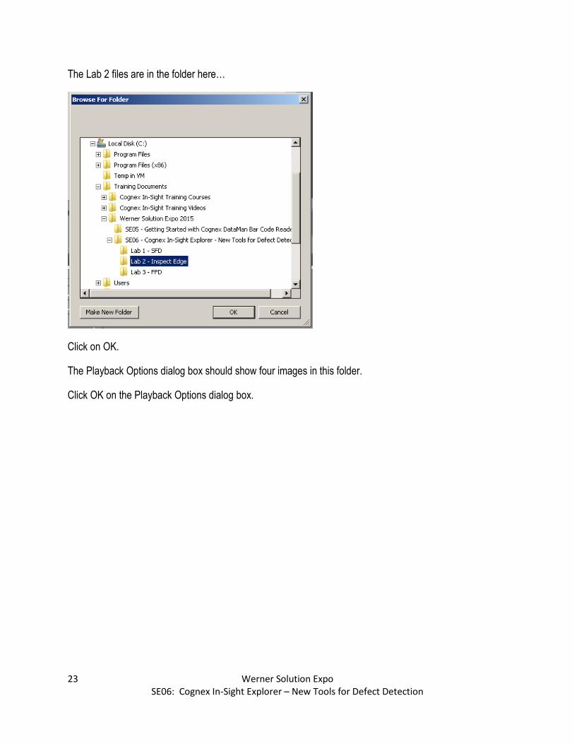
The Lab 2 files are in the folder here…
Click on OK.
The Playback Options dialog box should show four images in this folder.
Click OK on the Playback Options dialog box.

24 Werner Solution Expo SE06: Cognex In-Sight Explorer – New Tools for Defect Detection
The Emulator image should update, and the filmstrip should show the following…
Cycle through the images to see the defect types. The last two images show large chunks out of the solar
panel, we will create an edge defect inspection too find these defects.
Note: Return to Image 1 before moving to the next step.

25 Werner Solution Expo SE06: Cognex In-Sight Explorer – New Tools for Defect Detection
Step B: Add a PatMax Locator Tool to Track Part Movement in the Image
1. Click on “Locate Part” in the Application Steps menu on the left.
2. Click on “PatMax Pattern” in the Location Tools pallet in the lower left hand corner.
3. Click on Add
26 Werner Solution Expo SE06: Cognex In-Sight Explorer – New Tools for Defect Detection
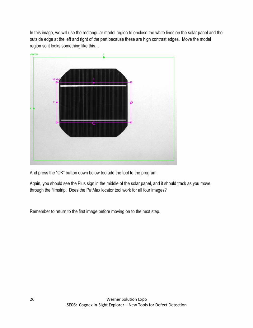
In this image, we will use the rectangular model region to enclose the white lines on the solar panel and the
outside edge at the left and right of the part because these are high contrast edges. Move the model
region so it looks something like this…
And press the “OK” button down below too add the tool to the program.
Again, you should see the Plus sign in the middle of the solar panel, and it should track as you move
through the filmstrip. Does the PatMax locator tool work for all four images?
Remember to return to the first image before moving on to the next step.
27 Werner Solution Expo SE06: Cognex In-Sight Explorer – New Tools for Defect Detection
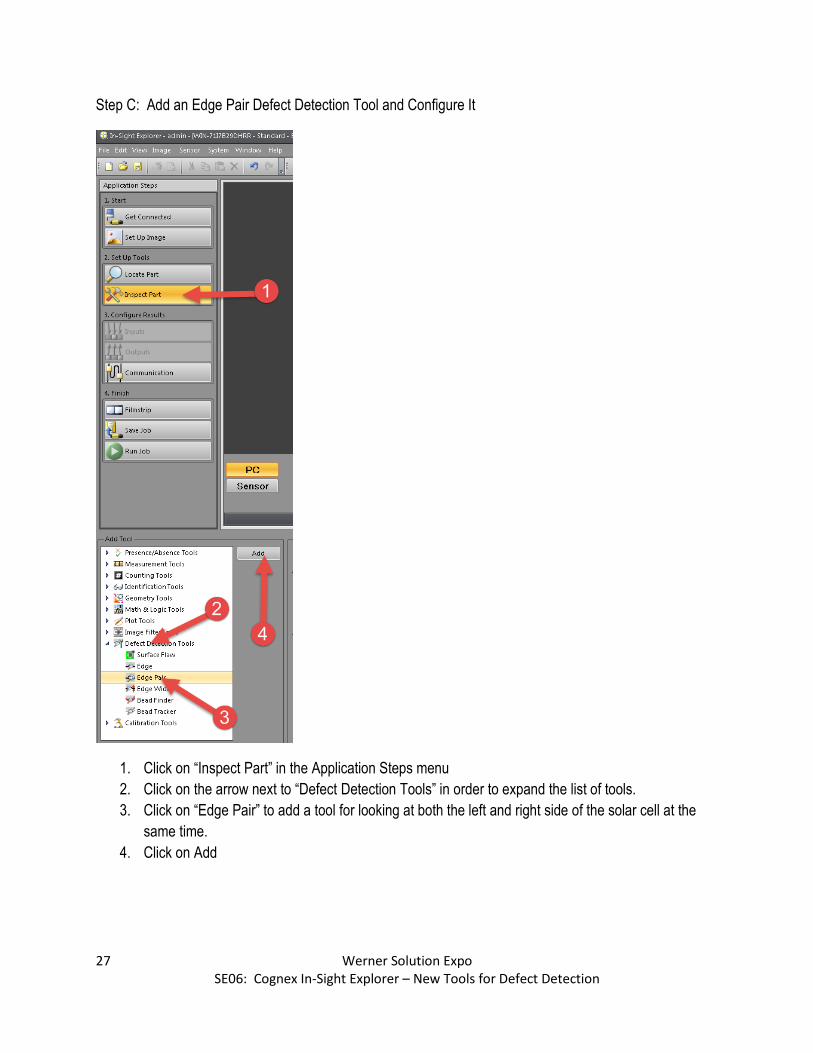
Step C: Add an Edge Pair Defect Detection Tool and Configure It
1. Click on “Inspect Part” in the Application Steps menu
2. Click on the arrow next to “Defect Detection Tools” in order to expand the list of tools.
3. Click on “Edge Pair” to add a tool for looking at both the left and right side of the solar cell at the
same time.
4. Click on Add
28 Werner Solution Expo SE06: Cognex In-Sight Explorer – New Tools for Defect Detection
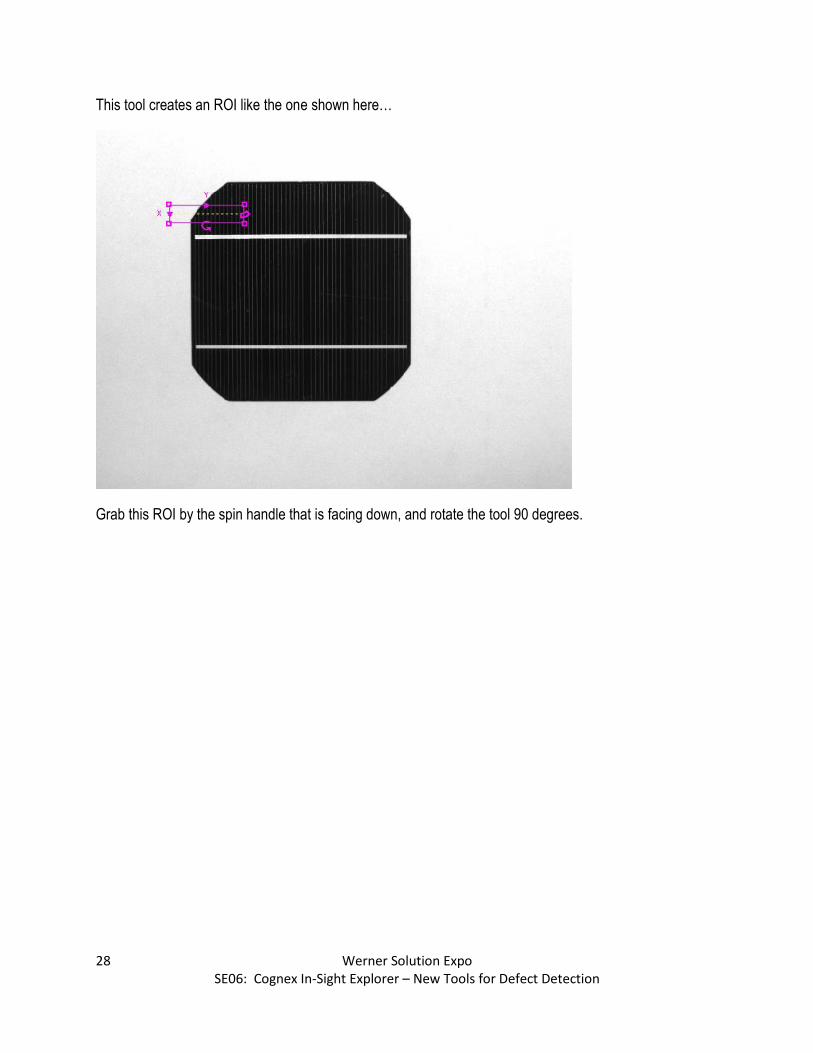
This tool creates an ROI like the one shown here…
Grab this ROI by the spin handle that is facing down, and rotate the tool 90 degrees.

29 Werner Solution Expo SE06: Cognex In-Sight Explorer – New Tools for Defect Detection
Then, resize the tools so that it is outside both the left and right sides of the solar panel, like shown here…
Then, press OK.
Note: the default settings for the tool are wrong for this application, so the first image will be a failure until
we have properly configured the tool. This is expected.
The first page of settings to be edited is called “Edges”…
The Minimum Contrast on this applications is too low so change that setting to 30.

30 Werner Solution Expo SE06: Cognex In-Sight Explorer – New Tools for Defect Detection
The second tab is Edge Scoring…
The Find Edge Direction should be set to “Outside In”
Does the inspection work better now?
Does it work for all the images provided?
Does this vision tool highlight the location of defects in the image?
31 Werner Solution Expo SE06: Cognex In-Sight Explorer – New Tools for Defect Detection
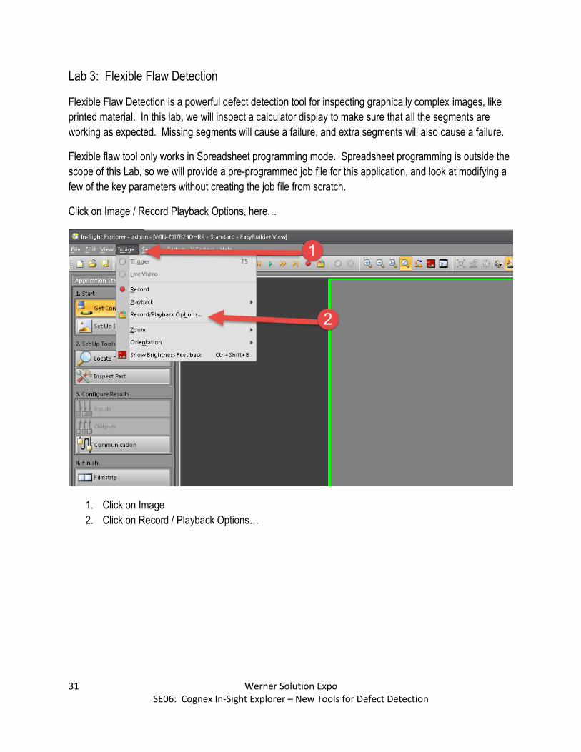
Lab 3: Flexible Flaw Detection
Flexible Flaw Detection is a powerful defect detection tool for inspecting graphically complex images, like
printed material. In this lab, we will inspect a calculator display to make sure that all the segments are
working as expected. Missing segments will cause a failure, and extra segments will also cause a failure.
Flexible flaw tool only works in Spreadsheet programming mode. Spreadsheet programming is outside the
scope of this Lab, so we will provide a pre-programmed job file for this application, and look at modifying a
few of the key parameters without creating the job file from scratch.
Click on Image / Record Playback Options, here…
1. Click on Image
2. Click on Record / Playback Options…

32 Werner Solution Expo SE06: Cognex In-Sight Explorer – New Tools for Defect Detection
The following dialog box appears…
Click the “…” button to change directories to the folder containing the images for Lab 3.

33 Werner Solution Expo SE06: Cognex In-Sight Explorer – New Tools for Defect Detection
These images are stored here…
Click on OK
On the Playback Options dialog box, you should see an Image Count of 11 Images.
Click on OK on the Playback Options dialog box.
The calculator display images should appear.

34 Werner Solution Expo SE06: Cognex In-Sight Explorer – New Tools for Defect Detection
Switch to Spreadsheet programming mode…
1. Click on the View menu
2. Click on Spreadsheet
The display will switch to spreadsheet programming mode; you should see the faint image of the calculator
beneath the spreadsheet.
35 Werner Solution Expo SE06: Cognex In-Sight Explorer – New Tools for Defect Detection
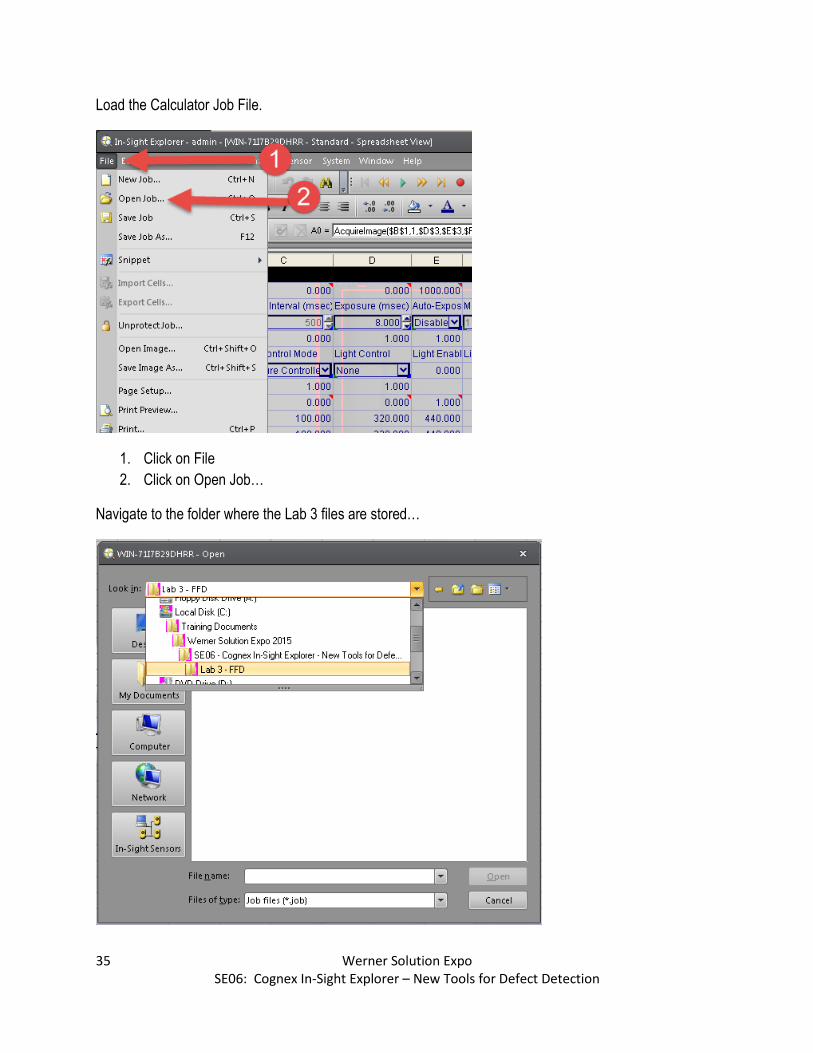
Load the Calculator Job File.
1. Click on File
2. Click on Open Job…
Navigate to the folder where the Lab 3 files are stored…

36 Werner Solution Expo SE06: Cognex In-Sight Explorer – New Tools for Defect Detection
On this dialog box…
1. Click on CalcDisplaySpreadsheet
2. Click on Open
You will be prompted…
Click Yes to load the new job file.
37 Werner Solution Expo SE06: Cognex In-Sight Explorer – New Tools for Defect Detection
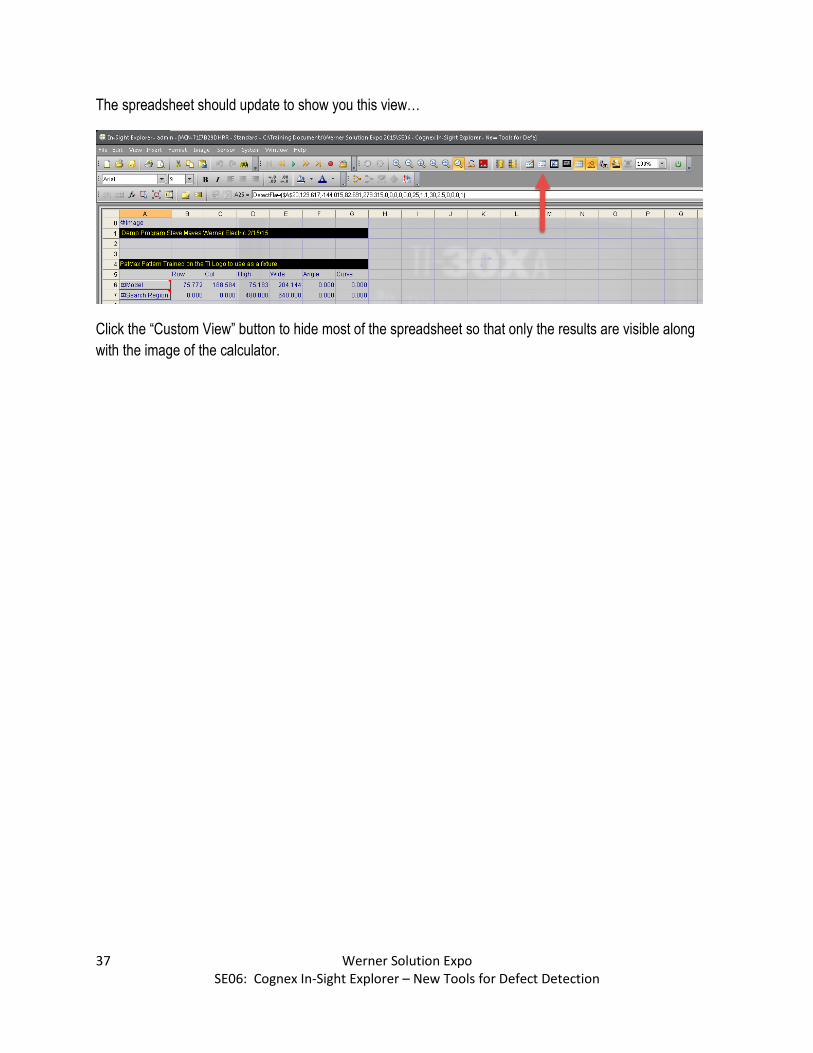
The spreadsheet should update to show you this view…
Click the “Custom View” button to hide most of the spreadsheet so that only the results are visible along
with the image of the calculator.

38 Werner Solution Expo SE06: Cognex In-Sight Explorer – New Tools for Defect Detection
As shown here…
Double Click the DetectFlaw tool in the CustomView display.
39 Werner Solution Expo SE06: Cognex In-Sight Explorer – New Tools for Defect Detection
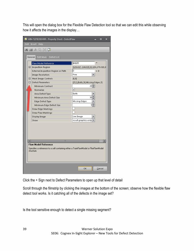
This will open the dialog box for the Flexible Flaw Detection tool so that we can edit this while observing
how it affects the images in the display…
Click the + Sign next to Defect Parameters to open up that level of detail
Scroll through the filmstrip by clicking the images at the bottom of the screen; observe how the flexible flaw
detect tool works. Is it catching all of the defects in the image set?
Is the tool sensitive enough to detect a single missing segment?
40 Werner Solution Expo SE06: Cognex In-Sight Explorer – New Tools for Defect Detection
Try raising the minimum contrast level to 50, what happens?
If you return the minimum contrast level back to 25 and turn off Normalize, what happens?
Note: Normalize is able to compensate for brightness changes, so turning it off makes the inspection less
able to deal with lighting variations.
Change the Area Defect Type, how does that affect the results?
If time allows, try changing some of the other settings and see how they affect performance.