se ,/aik s £rrftsmrn® - c.searspartsdirect.com · for one year from the date of purchase, when...
TRANSCRIPT

_IPORTAN_ MANUAL
Operator'sManual
MODEL NO.
358.798260-32cc
_D__ brow
• CUSTOMERASSISTANCE "---
_1-800-235-5878 _ Always Wear Eye grotectWn
_-_ SE_,/AIk_S/ £RRFTSMRN®
32cc GAS BRUSHWACKER TM
Fuel Mix40:1
• Maintenance
• Repair Parts
A DANGER:
Read the Operator'sManualand Follow All Warningsand Safety Instructions.Failure ToDo SoCanResuitin Serious Injury.
2 Cycle Engine
• Assembly
• Operation
sears,RoebuckandCo., HoffmanEstates,IL 60179 U,S.A.

For one year from the date of purchase, when this Craf_man Gas-Powered Brushwaeker is maintained, lubricated, and tunedup accordingto the operating and maintenance instructions in the operator's manual, Sears will repair, free of charge, any defectin materials or workmanship. • •This warranty excludes the blade, nylon line, spark plug, and air filter, which are expendable parts and become worn duringnormal use.
If this Brushwacker is used for commercial purposes, this warranty applies for only 90 days from the date ofpurchase. If thin Brushwackeris used for rental purposes, this warranty applies for only 30 days from date of purchase. Th_ warranty applie s only while this product is inuse in the United States.WARRanTY SERVICE IS AVAILABLE BYRETURNING THE BRUSHWACKER TO THE _ST SEARS SERVICE CENTER IN THEUNITED STATES.
This warranty gives you specific legal rights, and you may also have other rights which vary from state to state.SEARS, ROEBUCK AND CO. DEPT.817WA HOFFMANESTATES, rL 60179
TABLE OF CONTENTS;_VA--I_INGS,_6§T_E_r_ ;ir_sT_p_TioNs....._ ....._._.,..--3F - owYOURTOOL......................................................SASSEMBLY....................................................................6FUELhNG YOUR ENGINE ............................................ 11STARTING YOUR ENGINE .................................... ...... 12
USING YOUR TOOL AS A BRUSIICUTTER ......... : ....... 14
USING YOUR TOOL AS A LINE TRIMMER ................. 16
ACCESSORIES ............ . ..... ; ......................................... 20CUSTOMER RESPONSIBILITIES ................................ 21REPAIR PARTS LIST ................................................... 28
INDEX ............... . ......................................................... 3
2
SPECIFICATIONS
"ENGINE TYPEi 2-C_l'e. Air-C(_fied
DISPLACEM E NT: 32¢c
RPM: Operating -- 7500ENGINEIdle - 2800- 3200
Solid StateIG NtTION:
IGNITION TIMING:
CARBURETOR:
"ENGINE "'OFF":
STARTER:
MUFFLER:
CLUTCH:
FuELTANK: ........
SHAFTL_NGTHiSPARK PLUG"
SPARK PLUG GAP:
MODULEAIR'GAP:
LUBRICATION:
"CUTTING LINE:
Spark Advance --Non-adjustable
Diaphragm All l_sitions withadjustable fuel mixture jet.,,
Push Button"
Auto Rewind
Temperature 'Limiting (not sparkarresting; see Notice, p.6) :
Centrifugal ..........
17 ft. oz.
51"71-8585'4 (Cj-t4) .....
.025"
.0t0 1.014
.... GasolinetOil Mixture-40:!
.080" Diameter Sears LaserLine ®
BLADF, 4 pointB'"w_ Blatl_I_ER LINE" IS A REGISTEREDTRA'DEMARK OF '"
WHITE CONSOLIDATEDINDUSTRIF._,INC.
STARTER ROPEHANDLE SHOULDER STRAB,
SERIAL NUMBER AND PLASTICSTARTINGINSTRUCt!ONS S_
X
FUEL _
CHOKE
MANLt_ACTTII_D UNDER ONE OR MOI_ OF THE FOI,,I_WI_(] LLS.PAI'g/ITS:4,03_,!1121 4,0_2,'/8S; 4,II2,SS:I; 4,181,S_0; 4,1_ff, lll_; 4, 183,158; 4;1811,83,_1 4#111,004;4,_SS,(I'/8| 4,362,074; 4,451,983; 4,'/98,t8_; 4,823,468; 4,S41,929; 4,S40,0281 8,0g0,225; &D324,0Sl. OTItER U,S, AND FOREIGN PATENTS PENDING.
METALSHIELD
LINE TRIMMERLIMrlXR HEAD
_-_ AIR-FiLTER
GUARD
SPARK PLUG
/4 TOOTH
WEED BEADE

WARNINGS AND SAFETY INSTRUCTIONS(See Additional Safety Instructions throughout this Manual)
Jk DANGER -- THIS POWER TOOL CAN BE DANGEROUS! Tht, unit ca,, cause serionsinjury including amputation or blindness to the operator and others. The warnings and safety instruc-tions in this manual must be followed to provide reasonable safety and efficiency in using the unit. Theoperator is responsible for following the warnings and instructions in this manual and on the unit. Readthe entireOperator's.Manualbeforeassemblingand usingtheunit!Restricttheuse ofthisunittopersonswho read,
understand,and followthe warnings and instructionsinthismanual and on theunit.
8LADE
Jik DANGERBLADE CAN THRUST VIOLENTLYAWAY FROM MATERIAL IT DOES
- NOT CUT.
-- BLADE THRUST CAN CAUSEAMPUTATION OF ARMS OR LEGS.
- KEEP PEOPLE AND30 FEET (10 METERS) AWAY.
i£ I "AWARN
Leg Guards Thrown_ TRIMMER LINE CAN THROW
• - YOU CAN BE BLINDEDOR INJURED°
- wE__ ANYLEGProtection B PROTECTION.
in
60 Foot (20meter)Hazard Zone
Jk WARNINGHAZARD ZONE FOR THROWNOBJECTS.
- BLAD_ LINE CANTHROW OBJECTS VIOLENTLY.
- OTHERS CAN BE BLINDEDOR INJURF_.
- KEEP PEOPLE AND ANIMALS30 FEET (I0METERS) AWAY.
,r r |1, ,r r , |, , ,,, I ' _ r
Stop Coasting
I_ Blade by Contact A WARNING_/_ Blade __ _. with Cut BLADE COASTS AFTER THE
CUT YOU Ol
STOP THE IMATERIAL.
TtlROTT_ IS RELEASED.
- THE BLADE CAN SERIOUSLYCUT YOU OR OTHERS.
- STOP THE BLADE WITH CUT
• n nl ml i| i
%,
Manual
A WARNING
OPERATOR'S MANUAL.- FOLLOW ALL WARNINGS
AND INSTRUCTIONS.
+ FAILURITODO80CANRESULT IN SERIOUS INJURY.

WARNINGSAND S ETY INSTRUCTIONS....(Continued)
Ak OPERATOR SAFETY• Always wear safety eye protection.• Always wear heay3_ long pants, long sleeves,
boots, and gloves. Wearing safety leg guards is rec-ornmended_ Do not go barefoot or wear sandals,jewelry, short pants, short sleeves, loose clothing,or clothing with loosely hanging ties, straps, tas-sels, etc.; they can be caught in moving parts. Be-ing fully covered will help protect you from piecesof toxic plants such as poison ivy thrown by bladeor trimmer head which could be more of ahazardthan touching the plant itself.
• Secure hair so it is above shoulder length.• Do not operate unit when you aretired, ill, or un-
der the influence of alcohol, drugs, or medication.• Wear hearing protection if you use the unit for
more than 1-1/2 hours per day.• Never start or run the engine reside a closed room
or building. Breathing exhaust fumes can kill.• Keep handles free of oil and fuel.• Alwaysuse the handlebar and a properly adjusted
shoulder strap with a blade. See '7_ssembly."
A UNIT/MAINTENANCE SAFETY• Look for and replace damaged or loose parts be-
fore each use. Look for and repair fuel le_ beforeuse. Keep the unit in good working condition..
• Throw away blades that are bent, warped,cracked, broken, or damaged in any other way.
Replace trimmer head parts that are cracked,chipped, broken, or damaged in any other way be-fore using the unit.
• Maintain the unit according to recommended pro-cedures. Keep theblade sharp. Keep the cuttingIine at the proper length.
• Use only .080" diameter SEARS Laser Line _.Never use wire, rope, string, etc.
• Insta_ the required shield properly before usingthe unit. Use the metal shield foor all weed bladeuse. Use the plastic shield for all line trimmer use.
• Use only specified blade or trimmer head; makesure it is properly installed and securely fastened.
• Never start engine with clutch shroud removed.The clutch can fly off and cause serious i_ury.
• Be sure btade or trimmer head stops turning whenengine idles.
• Disconnect the spark plug befo_ performingmaintenance (except carburetor adjustments).
• Make carburetor adjustments with the lower endsupported to prevent the blade or trimmer linefrom contacting any object. Hold the unit by hand;do not use the _oulder strap for support.
• ' Keep others away when making carburetor ad-justments ..........
• Use only genuine SEARSaccessories as recg_m--__mended forthisunit. _
• Have all maintenance and service not explainedin this manual performed hy ar_ Authorized Ser-vice Dealer.
A FUEL SAFETY• Mix and pour fueloutdoors.• Keep away from sparksor flames.• Use a containerapproved forfuel.• Do not smoke or allowsmoking near fuelor the
unitorwhile usingtheur.lt.• Wipe up.allfuelspillsbeforestartingengine.• Move atleast10 feet(3meters)away fromfueling
sitebeforestartingengine.• Stop engineand allowunitto coolbeforeremov-
ingfuelcap.• Empty the fueltankbeforestoringtheunit.Use
up fuelleftinthe carburetorby startingtheen-gineand lettingit_ untilitstops.
• •Storeunitand fuelm an areawhere fuelvaporscannot reach sparksor open flamesfrom waterheaters,electricmotorsorswitches,furnaces,etc.
A CUTTING SAFETY• Inspect the area to be cut before each use. Remove
objects(rocks,broken glass,nails,wire,string,etc.)which can be thrown orbecome entangledinthebladeortrimmer head.
• Keep othersincludingchildren,animals,bystand-ers,and helpersoutsidethe 60 foot(20 meter)Hazard Zone.Stopthe engineimmediatelyifyouareapp_ached. . •
• Always _ engine on the right-hand side of
our body. hands• _Id theunitfirmlywith both
• Kee_ firm footingand balance.Do not over-reacn.
• Keep blade or trimmer head below waist level.• Do not raise the engine above your waist.• Keep _l parts of your body away from blade, trim-
mer head, and muffler when engine is runnnmg.• Cut from your righttoyour left.• Use onlyforjobsexplainedinthisman_laL
TRANSPORTING AND STORAGE• S_p the unitbeforecarrying.• Keep the muffleraway from your body.• Allow engineto cooland secureunitbeforestor-
ing ortransl_brtingitina vehicle.• Empty the fueltank beforestoringor transport-
ingtheunit.Use up fuelleftinthe carb.ur.etorby•s__e engineandlettingitrununtilitstops.
• Store unit and fuel in an area where fuel vaporscannot re_h sparks or open flames from waterheaters,electricmotorsorswitches,furnaces,etc.
• Storeunitsothebladeorlinelimitercannotacci-
denny causeinjury.The unit'canbe hung bythebracketbelow engineorby tube.
• Store the unit out of reac2x of children.

iii ill i inn i i ...,, ii i,,.,,
KNOW YOUR TOOLill IIIIIIIIII I IIH
Your Weedwacke:" is a high quality product designed fortough jobs. Its versatility will help you make short workof a variety of jobs.
Special Features Include: ,• Reversible,l-point Weed Blade for grass, weeds and
brush up to ½ inch in diameter. ....... -
• Semi.automatle line feed trimmer laeadfor trim-.,-.-ruing, mowing, Sweeping, and scalping ..... . • '
-,-'.jB. UNPACKING INSTRUCTIONS " -'i
1. Remove contents from the carton if you lhave not
C. CARTON CONTENTSKEY
done so.
2. Check part,sagainst the list below.3. Examine parts for damage. Do notusedamaged parts.4. Notify your Sears Store immediately if a part is miss-
fuel tank.
EngineDdve Shaft/BearingHousing Assembly
w/Safety LabelsHandlebarPlastic Shield- TrimmerHeadTrimmer HeadMetal Shield-BladeWeed Blade - 8 inch, 4-pointShoulder Strapw/Warning2-cycle EngineOilOperator's Manual(not shown)
.l._ose PartsBag (notshown)
** LOOSE PARTS BAG CONTENTS:
QTY,
11
......... 4 ....................
11!
lI
1
iI
L,_-[)..... Moh-iii,ing Block- Handl-ebar 1
-4- Cover- Handlebar 2ShoulderStrap Clamp !
- ;- T-Handle i" - .... Hex Wrench - Small 1
ing or damaged. '-*' Hex Wrench - Large 1Your unit has been shipped with abl_ie--" i - "-' FlexShaft tube 1
shipping guard over the primer bulb (see I A. HexScrew-Engine 2"Specifications"for location).Remove and i: B. - Screw_2Handlebar ...... 8
• discard the plastic shipping guard. __[_ C_ _.i_Hex'Se_-iThrdtt-le--'i;ri_er H0_using .... 1.......... D, Screw- Plastic Shield 4
NOTE: It is normal to hear the fuel filter rattle in an empty -zS Square-Head Screw 1
* .:g . Fiat Washer - Blade I
'_I(G_ BeveledWasher - Blade 1*;'H2 Flange Hex Nut -Blade i
) , '17" ._ Hex_Nut-E..ngine 2---_J7-, Hex Nut 1
t_--'7-. -Large CupWasher - Trimmer Head 1* -L_- RetentionPlate - MetalShield 1
D. HARDWARE USAGE--. q
NOTE'. ThisHardware ispackaged inthePl_ticBag. Referto"the Hardware referencelettersbelow duringassembly. _
-f
, HARDWARE SHOWN ACTUAL SIZE
• . T K°
L,

ASSEMBLY(If toolis received assembled, repeat all steps in this section to be sure assembly is correct pad is ad-justed for the operator.)
:i
PREPARATIONThis Manual is designed to help you assemble the tooland to provide its safe operation. It is important thatyou read the entire manual to become familiar withthe tool before you begin assembly. If you have anyquestions or need further assistance, call ourCUSTOMER ASSISTANCE HOTLINE at1-800-235-5878.
1. Read your Operator's Manual _2. Tools you will need:
- Hex Wrench provided with the tool.
- Adjustable Wrench
- Standard Screwdriver
ASSEMBLY STEPS (Referto illustrations)TUBE• Place the two screws "A." into the holes on the
engine as shown in the illustration. Make surescrews are fully seated in the holes.
• Position the. nuts. "l. "in the lower holes.• • Tighten the screws with the hex wrench (pro-
vided) just enough to hold the hardware to-gether while holding the locknuts with yourother hand.
• Remove the pacldng cover from the straightend of the shaft housing if so equipped. Yourunit may not have a packing cover.
Make sure the shaft inside the tube doesnot fall out of the tube. Dirt on the shaft will sig-nificantly reduce the life of the unit. If the drive
shaft falIs out ofthe housing, clean, re-lubricate,and re-install. See "Drive Shaft Lubrication inthe Customer Responsibilities section.
• Align the'_bottom groove on the tube with theridge on the lower wail of the engine opening.
• Turn the shaft to align the square end of theshaft with the square hole inside the frontopening of the engine.
• Firmly push the tube into the engine openinguntil the top groove is no longer visible.
• Tighten screws "A." alternately with the hexwrench until secure.
9_..---- Screw "A"
. . ' • , •
,__ / Remove an, packin, materi._ "that may be on the end of thetube.
Ridgeand bottomgroove
Turn the arbor shaftto align the shaft withthe square hole.
-6-

2. THROTTLE C_,dlll-_
_r.._IYI'ION:3 Do not kink the throttle cable ....... i
a: SlideFoamtheThrottleGrip. Trigger Housing away from the . ,_ _1 IIJ_r-I_ _ltf ....
'NOTE: Before performing step "b", push the barrel _ 0'__
_the throttle cable into the sheath until the _ ] [,,I,_q¢barrel contacts the sheath. ' ! _.._'€_ I \,
b Insert the Throttle Cable through the tunnel in _he no, rsnno'_ Jl \Foam Grip until the end of the Cable extends at ...... N: .... ],], aAu_n_least 2 inches beyond :the Grip. TRIGGER j ], I _I_O'F"
c. Hold the Trigger away from the Drive Shaft Hous- -I- _._ C._LZing and insert the barrel end of the Throttle Cable , '......................7--
into the round_ opening in the Trigger._.
-_-_E.:--°When inserting the barre! end °ft-he
Throttle Cable into the round opening in theTrigger, make sure that the barrel is completelyinserted and the Throttle Cable is located in 'the splitin the Arm.
d. Push the Trigger back into the Housing while guid -
ing the Cable through the split in the art 9. Guide_the arm into the Foam Grip tunnel while replacing,
the Throttle Trigger Housing trash againstthe Grip__
e. Hold Trigger_against the Foam Grip while insert-"
ing the screw "B." and Nut "I." See Caution below.
[CAUTION: ('Do notovertig-htenihe screw. Makesure the trigger will move freely. There must be at •least 1!8"free play in the trigger. Make sure thetrigger will move freely so the engine can fullyreturn to idle when the trigger is released. The--trimmer head must not turn at idle_speed to avoidserious injury to the operator and others.
3. HANDLEBAR •
ARM
Nut
alXWARNING
The handlebar mountingblock must be placed above the
point of the arrow on the safety labels. The handlebaris a barrier to keep the blade away from the operator'sfeet.
a. Position either side of the mounting block on thedrive shaft Housing above the arrow on the SafetyLabels.
b. Place one of the covers below the drive shaft Hous-
ing and secure it to the mounting block with 2
c. Align the Handlebar with the straight barrier por-tion to the left and the curved portion to the right. _
d. Position the Mounting Block between the arrows
on the short, straight section of the Handlebar.e. Place the remaining Cover over the Handlebar and
secur e it with two_re__WSs_iC_":,finger tightenordy.- [ .
f. Be sure the Handlebar is installed correctly, then
.... tighten each screw securely with a wrench.
AWMUIDI0The long, straight portion of the Handlebar must be
installed to provide a barrier between the operatorand the spinning blade.
SAFETYLABELS
/
:C
CABLE

I I I I illllIl I IIIIII
B.FOR LINE TRIMMER USE _ ,,:
: A WARNINGfiastic shield must be ' installed for
trimmer shield pro-risk of thrown
ecte to operator and others and iswith a line limiter which cuts excess
the proper length.
AWARNI_G : ._.:Failure to install shield in the position showncan result in serious injury to the oper*ator. The length of the shield must be alignedwith the length of the drive shaft housing. Di-rect the widest part of shield toward the engine.
NOTE." Remove the metal shield and blade before• installing the plastic shield and trimmer head.1. Place the shield under the bearing housing and
_.align screw holes. .......... _=The line limiter (on the underside of
the shield) is sharp and can cut you,2. Insert screws "D." through the bearing housing
into the shield.31 Tighten the screws evenly and securely.4. Remove the packing cover from the arbor shai_ if so
equipped.5. Install grass washer "K? over the arbor shaft Make
sure the grass washer is against and curved over thedust cup.
6. Start thread_g tl_e trimmer head onto the arborshaft.
7. Align the hole in the dust cUp with the hole m thecenter front of the bearing housing by turning medust cup. Then, insert the small hex wrench (pro-vided) into the aligned holes to keep the arbor shat_from turning.
8. Tightenthetrimmer head againstthewasher anddustcup whileholdingthehex wrench.
9. RemOve the hex wrench.To remove the trimmer head, insert the
hex wrench into the aligned holes in the dust cupand bearing housing. Unthread the trimmer head.Be sure to store grass washer"K?, plastic shield, 4shield screws, and hardware with the trimmer headfor future use.
BearingHousingClamp
Hex Screw D.
Dust Cup
!Widest Part Lineof ShieldTowardEngine
Directionto Install
Arbor Shaft
GrassWasher K.
Trimmer
8

" S. mR WEEDnLADEUSE
The metal shield must _ properly installed onanytime the tool is used with the blade. The forward tipon the metal shield helps to reduce the _ of bladethrust which can cause serious injury such as amputa-tion to the operator or bystanders.
& w a,.NmG • • •Failure to install the shield in the position shown
can result in serious injury to the operator. The
length of the shield must be aligned with thelength of the drive shaft housing. Direct the widestpart of the shield toward the engine. ::
[CAUTION:] Wear protective gloves when
handling or performing maintenance on the blade to
help avoid injury.
NOTE: Remove the Plastic Shield, Trimmer Head,and Grass Washer before installing the Metal Shieldand Blade.
a. Place the Metal Shield under the Bearing Housing,aligning screw holes. Be sure wide end of metal shieldis toward the engine.
b. Position the retention plate "L." on the undersideof the Metal Shield and align screw holes. Make sure theflat side of the Plate is against the Shield.
c. Insert screws "C." (one at a time) through theBearing
Housing,. Shield, and Retention Plate.
d. Tighten the Screws evenly and securely with a hexwrench.
e. Install the Dust Cup over the Arbor Shaft.
f. Install the Blade over Arbor Shaft, making sure thehole in the center of the Blade is fitted around the raised
center step on the Dust Cup.
g. Install fiat washer E , cupped washer G. , and.................. tailednut I L ; De sure cuppea WaSher t,. is ms
as shown in (lower inset).
h. Line up the hole in the Dust Cup with the hole iri theside of the Bearing Housing by turning the Dust Cup.
i. Insert the small hex wrench provided into the aligned
holes to keep the Arbor Shaft from turning.
j. Tighten nut 1"II." fuanly with a wrench while hold-ing hex wrench in position.
k. Remove the hex wrench.
I. Turn Blade by hahd. If the Blade binds against theShield, the Blade is not centered. Reinstall the Blade.
m, Proceed to "Should Strap" instructions, this section.
NOTE: To remove the Blade, insert rod into
aligned holes. Unthread the Hex Flange Nut and
, remove parts. Be sureto store the Retention Plate,Hex FlangeNut, BeveledWasher,Flat Washer andMetal Shield with the Blade for safe keeping.
/-r--, W88tle, r _.J,
"(see inset)
X _'Nut "H "*
Cupped SideTowardBlade _! washer .'
* £WARNING ]Parts .no.ted with * are critical and must besupphed by Sears. Failure to use proper parts
can cause the blade to fly off and seriously hurt
}_t or.qtMrs, :
9

6. SHOULDgl STR.Ar _ ....
a. _gn the sh?ulder s_ap cIampbetween the assisthandle and the throttle trigger housing. ...........
b. Firmly push the shoulder strap clamp onto thedrive shaft housing. Be sure that the shoulder
strap clamp is installed with the hexshaped recesmon (on-the clamp) facing the sameside of the drive shaft housing as the barrier por-tion of the handlebar.
c. Drop.the threaded end of screw _"ES through theopening in the top of the T-handle.
d. Pull on the threaded end of the screw to bring thesquare head of the screw past the pin inside theT-handle.
e. Seat nut ",l." in the hex-shaped recession on theback side of the shoulder strap damp. ........
f. Insert the threaded end of screw "E." through thehole in the shoulder strap clamp; thread the screwinto nut "J." and tighten fn_nly by hand only.
7. SHOULDERSTRAP
I. Try on shoulder strap and adjust for fit and balancebefore starting the engine and beginning a cuttingoperation.
2. Place shoulder strap on your left shoulder with theDanger _ign on your back and hook to the right sideof your waist.
NOTE." A one-half twist is built in the shoulder strap' to allow the strap to rest fiat on the shoulder.To make sure the strap rests fiat on your bo_v,place the double portion across your front and thesingle portion across your back.3. Adjust the strap so that the hook will be about 10 in-
ches below the waist when the hook is attached tothe shoulder strap.
!4. Fasten the shoulder strap hook to the clamp and liftthe tool to the operating position.
5. Check for the foUowing_.a. Leftarm fully extended, handholdinghandlebar
grip.b. Right hand holding the top handle, fingers on
the throttle trigger.c. Engine below waist level.d. Shoulder strap pad centered on left shoulder.e. Danger sign centered on your backf. Full weight of tool on left shoulder.g. Without operator bending over, the blade or
trimmer head is near and parallel to the groundand easily contacts material to be cut.
6. Modify these initial adjustments as necessary forcomfort and control but do not locate the handlebarmounting block below the point of the arrow on thesafety labels, Do not locate the shoulder strap clampin anypoaiti0notherthanb0tw n on o andban.dlebar mounting block.
7. Position the handlebar for height.8. Be sure the handlebar is installed correctly, then
tighten each acrew _urely with the large hexwrench.
Shoulder
Strap
OPERATING POSMOH
Danger SignCentered onYour Back
RotationDirection
POSITION HANDLEBAR FOR
_. , OPERATING HEIGHT "Over 6 4---- 6' to 5' 5"

I I II III II I II I BI II BIBLE llll IIIIIIIII I I I IIIIIII lllllll I IIIIII IIIIII,i i iii , H ,,,,,,,,,,
FUELING YOUR ENGINE
BEFORE FUELING ENGINE:
A WARNING
Be sure to read the fuel safety information in the Warn-
ing s and Safety Instructions section on page 4 of thismanual before you begin.If you do not understand the fue! safety section DO NOT
attempt to fuel your unit; seek help from someone thatdoes understand the fuel safety section or call the Cus-tomer Assistance Hotline at 1-800-235-5878.
GASOLINEThe two-cycle engine on this product requires a fuel mix-ture of regular unleaded gasoline and a high quality en-gine oilforlubrlcal;ionofthe bearingsand othermoving
parts.The correctfuel/oilmixtureis40:1(seeFuelMix-
ture Chart).Too littleoilor the incorrectoiltype will
causepoorperformance and may causetheenginetoover-heatand seize.
Gasolineand oilmust be premixedina cleanapprovedfuelcontainer.Always use freshregularunleaded gasoline.
IMPORTANT: Experience indicatesthat alcoholblendedfuelscalledgasohol(orusingethanolormetha-nol)can attractmoisture,which leadstooil]gassepara-tionand formationofacidsduringstorage.Acidicgas
can damage thefuelsystemofan enginewhileinstorage.To avoid engine,problems,the fuelsystem should beemptiedbeforestoragefor30 daysorlonger.Drain thegastank,thenrun thefueloutofthecarburetorand fuellinesby starting;theengineand lettingitrun untilitstops. Use fresh fuelnext season. See STORAGEinstructionsforadditionalinformation.Never use en-
gineor carburetorcleanerproductsinthe fueltauk orpermanent damage may occur.
FUEL STABILIZERFuel stabilizer is an acceptable alternative in minimizing
the formation of fuel gum deposits during storage. Add
stabilizer to gasoline in fuel tank or storage container.Always follow the fuel mix ratio found on the stabilizercontainer. Run engine at least 10 minutes after addingstabilizer to allow the stabilizer to reach the carburetor.
You do not have to drain the fuel tank for storage if you are
using fuel stabilizer.
CRAFTSMAN 40:1 2 cycle engine oil is specially blendedwith fuel stabilizers. If you do not use this Sears off, youcan add afuelstabilizer(suchasCraftsman No. 33500)to
your fueltank.
2-CYCLE OIL:
CRAFTSMAN 40:1 2 cycle oil is strongly recommended.This off is specially blended with fuel stabilizers forincreased fuel stability (extends fuel life up to 5 timeslonger) and reduced smoke.
If CRAFTSMAN 2 c_ycle oil is not available, use a goodquality 2 cycle AIR-COOLED engine oil that has arecommended fuel mix 40:1.
IMPORTANT! Do not use:
* AUTOMOTIVE OIL
. BOAT OILS (NMMA, BIA. etc.)
These oilsdo not have properadditivesfor2-cycle,AIR-COOLED enginesand can causeenginedamage.
GASOLINE AND OIL MIXTURE
Mix gasoline and oil as follows:
• Consult chart for correct quantities.
• Do not mix gasoline and oil directly in the fuel tank.
FOR ONE GALLON:
• Pour 3.2 ounces of high quality, 2-cycle engine oilinto an empty, approved one gallon gasoline con-tainer.
• Add one gallon of regular unleaded gasoline to thegallon container, then securely replace the cap,Shake the container momentarily.
• The mixture is now ready for use. Fuel stabilizer
can be added at this time if desired; follow mixing
instructions o_he label.
FUEL MIXTURE CHART
40:1 Fuel:Oil MAx Ratio
Gasoline Oil (ft. oz.) - -iJ
[1 gallon 3.2
1.25gallons 4.0
2,5gallons 8.0
II

BEFORE STARTING THE ENGINE:
e Fuel engine. Move 10 feet (3 meters) away from fuel-ing site.
The trimmer head will turn when the enginestarts.
• • r
i i
C. STAITING'INSTRUCTIONS (For location of controls, refer to "Specifications")
• Rest engine and shield on ground, supporting trim-: mer head off ground.
Remove and discard the plastic shippingguard on the primer bulb (if so equipped).
STARTING A COLD ENGINE OR WARM ENGINEAFTER RUNNING OUT OF FUEL:
• Make sure the switch is in the "On" position.
• Move the choke lever to the "Full Choke" position,
• Slowly press the primer bulb 6 times.
• Squeeze and hold the throttle trigger. Keep thethrottle trigger fully squeezed until the engine runs
smoothly.
• PulI starter rope sharply 5 times.
NOTE." The enginemay sound as ifitistryin_tostart before the 5TM pull. If so, go to the next step :m-mediately.
• Move the choke lever to the "Half Choke" position.
• Pu_:the starter rope sharply until the engine runs,but no more than 6 pulls.
If the engine has not started al_er 6 pulls (athalf choke), check to make sure the switch and thechoke lever are in the proper positions. Then, movethe choke lever to the "Full Choke" position andpress the primer bulb 6 times; squeeze and hold thethrottle trigger and pull the starter rope 2 moretimes. Move the choke lever to "Half Choke" and pullthe starter rope until the engine runs, but no morethan 6 more pulls.
NOTE.* Ifthe enginestillh,asnot Started,itisprob-ably flooded. Proceed to Startinga Flooded Enogine."
Allow the engine to run 15 second_, then move thechokelever to "0ffChoke." AHow the unit torun for30 more seconds at "Off Choke" before releasing the
throttle trigger. .................
]N_Q_rEI Ifengine dies with the choke lever at the "OffChoke" position, move the choke lever to "HalfChoke" and pull the rope until the engine runs.
To stopthe engine,move the switchto "Off."
A WARNINGAvoid any bodily contact with the muffler whenstarting a warm engine. A hot muffler can causeserious burns.
ST O A WARMENOINB'THATHASRt_ OUT OF FU'_L,
• Make sure the switch is in the "On" position.• Move the choke levertothe "HalfChoke" position.
illll
• Squeeze and hold the throttle trigger. Keep thethrottle trigger fully squeezed until the engine runs •smoothly.
• Pull starter rope sharply until engine runs, but nomore than 5 pulls.
• Allow the engine to run 15 seconds, then move thechoke lever to "Off Choke."
NOTE." Ifenginehas notstarted,pullstarterrope5more pulls.Ifenginestilldoesnotrun,itisprobablyflooded.Proceedto"Startinga FloodedEngine."
To stoptheengine,move switchtothe"Off"position.
STARTING A FLOODED ENGINE: " •
Floodedenginescan be startedby placingtheswi,:tchinthe "On '_positionand the choke leverinthe OffChoke" position;then,pullthe ropetocleartheen-gineof excessfuel.This couldrequirepullingthestarterropemany timesdependingon how badlytheunit is flooded.If the unit still doesn't start, call the Customer Assis-tance Hotline at 1-800-235-5878,
!STARTING POSITION t
Switch
Choke Lever
12

D. OPERATING INSTRUCTIONS• When using the blade, bring the engine to fi_
throttle before entering the material to be cut. The
i
blade has maximum cutting power at full throttle andis less l_ely to bind, stall, or cause blade thrust,which can result in serious ir_jury to the operator orothers. Refer to "Guard Ag_i_t Blade Thrust".
• When using the trimmer_ead, do not run the en-gine at a higher speed than necessary. The cuttingline will cut efficiently when the engine is run at lessthan full throttle. At lower speeds, there is less enginenoise end vibration. The cutting line will last longerand will be less likely to "weld" onto the spool.
• If the blade or trimmer head does not turnwhen the engine is accelerated, make sure thetube is properly seated in the engine shroud.
• Always release throttle trigger and allow en-gine to return to idle speed when not cutting.
• The blade or trimmer head should not turnwhen the engine runs at idle speed. Ifthe bladeor trimmer head on your unit turns when the engineis at idle speed, refer to "Trouble Shooting Chart."
• To stop engine:• Release the throttle trigger.• Move ignition switch to the "Off" position.
Blade
12
Stop Coasting Bladeby Contact with Cut
Material.
The blade continues to spin after the engine isturned Off. The coastingblade can throw objectsor seriously cut you ff accidentally touched.Stop blade by contacting the left-hand side ofthe coasting blade with material already cut.
_k WARNING
* Stopthebladeby allowingthe"9o'clock"posi-tiontocontactcutmaterial.
The operator or others must not try to clearaway cut material with the engine running orthe blade turnin" g to avoid serious, injury. Sto_pengine and blade before removing materialswrapped around blade.
ii ill ii I i i I IIiiil I i I lllU II IIIIIIIIIIIIIIIIIIIIIIIIIIIIIIIIIIIIIIIIIII IIIIIIIIII
13

USING YOUR TOOL AS A WEEDCUTTER - wfBLADE(The 4 point, 8 inch blade is designed to cut grass, weeds and woody brush up to 1/2 inch diameter.)
Ak DANGER -THIS POWER TOOL CAN BE DANGEROUS!This tool can cause serious injury including amputation or blindness to the operator and others. The warnings and safetyinstructions in this manual must be followed to provide reasonable safety and efficiency in using this tool. The operator isresponsible.for following the warnings and instructions in this manual and on the tool. Read the entire Operator'sManual before using this tool! Restrict the use of this power tool to persons who read, understand andfollow the warnings and instructions in this manual and on the tooL
7 .......................
• i'
BLADE THRUST
/_-__ I" ARBOR
8 inch WEED BLADE
,, I60 Foot
. \ zo.
"-22J"S_,pco._gBl_
B_ _by Contactwith Cut__@_ Material.
_k DANGER - BI.ADE THRUST When the spin'ning blade contacts anything it doesnot cut, a dan-gerous reaction can occur causing the entire tool and
.... operator to be thrust violently in any direction. Thisreaction is called Blade Thrust. As a result, the op'erator can lose control of the tool. Use handlebar,shoulder strap, and keep shield in place.Make sure others are at least 30 feet (10 me-ters) away. Keep blade sharp. Cut at full..throttle and from your right to left. Keephands, feet and tool in proper position; refer to"Guard Against Blade Thrust."
_k DANGER - PROPER BLADEUs e only the 4point, 8 inch blade and properhardware. The use of any other parts can result inserious injury. Do not use any accessory or abtachment other than those recommended bythe manufacturer for use with th_s tool. Bladesthat are bent, warped, cracked, broken, or damagedcan fly apart and cause serious injury:Do not use.Throw away.
_k WARNING - THROWS OBJECTSThe rapidlymoving blade causes objects tO bethrown violently.The shieldwillnot providecom-
pleteprotectiontothe operatororothers.The op-erator must wear a safety face shield or gog-
eS, Always wear safetyleg guards and boots. °ep others at least 30 feet away.
WARNING - HAZARD ZONE
This tool will throw ob_yts and cut. Keep othersincluding chl]dren, animals, bystanders, andhelpers at least 30 feet (10 meters) away fromthe operator and tool. Stop the engine andblade immediately if you are approached.NOTE: In areas where other people and animals arepresent, such as near sidewalks, streets, houses, etc.,,t is strongly recommended that the operator use thebuddy system; that is, have another person serve asa "look out," keeping himself and others at least 30feet (I0meters) away from the operator.
lk WARNING - COASTING BLADE
The blade continues to spin after the engine isstopped or the throttle is released. The coastingblade can thrust, throw objects, or seriously cu.t youif accidentally touched. Stop blade by leaving ,tin contact with material already cut. Use the
"9 o'clock" potition u the point of contact.
14

A. BLADE SAFETY1. OPERATOR SAFETY
a. Always wear a safety face shield or gog.gles. See "Accessories,"
b. Always wear heavy, long pants, longsleeves, boots, gloves and safet_y legguards. See Accessories." Do not wear looseclothing, jewelry, short pants, short sleeves,sandals, or go barefoot. Secure hair so it isabove shoulder length.
c. Do not operate this tool when you aretired, iH or under the mfluence of alco-hol, drugs or medication.
d. Always use the handlebar and a properlyadjusted shoulder strap. See '_seml_ly."
e. Do not swing the tool with such forcethat you are m danger of losing your bal-8lice.
f. Never start or run the engine inside aclosed room or building. Breathing exhaustfumes can kill.
g. Keep handles free of oil and fuel.
2. TOOL SAFETYa. Inspect the entire tool before each use.
Replace damaged parts.Check for fuelle_and make sureallfastenersareinplaceand se-curelyfastened.
b. Be sure the metal shield is properly at-tached. The metal shield must be installed for
:_: all bladeusage.
c. Mak_sure the blade is properly installedand securely fastened. Refer to _'Assembly."
d. Be sure the blade stops turning when theengine idles. See "Trouble Shooting Chart."
e. Make carburetor adjustments with thelower end supported to prevent the bladefrom contacting any object. Hold tool byhand; do not use shoulder strap for support.
f. Keep others away when making carbure-
3. CUTTING SAFETY ....
a. Inspect the area to be cut before eachuse. Remove objects (rocks, broken glass,nails, wire, string, etc.) which can be thrown orbecome entangled in the blade.
b. Always keep the engine on the right sideof your body. Hold the tool rh-mly with both
"hands.
c. Keep firm footing and balance. Do notover-reach.
d. Keep blade below waist level.
e. Do not raisethe engine above your waist.The bladecan come dangerouslyclosetoyourbody.
f. Cut at full throttle.
g. Cut from your right to your left.h. Use only for jobs explained in this man-
ual. Do not use the blade as an edger. Theshield does not provide adequate protection.
B. GUARD AGAINST BLADE THRUST
• Blade Thrustisa reactionthatonlyoccurswhen
usin$ a bladedtool.This reactioncan causeseri-ous Lr_urysuch as amputation.CarefuU__ystudy.thissection.Itisimportantthatyou understand
••what causesbladethrust,how you can reducethechanceofitsoccurring,and how you canremainincontrolofthetoolifbladethrustoccurs.
• The forward tip on the shield helps to reduce theoccurrence of blade thrust but cannot prevent theoccurrence. The operator must follow the warn-ings and safetyinstructionsin thissection_tolessenthechanceofb!adethrustoccurringand tomaintaincontrolofthetoolifthereactiondoesoc-cur.
le WHAT CAUSES BLADE THRUST. B/adeThrust can occur when the spinningblade con-tacts an object that it does not cut. This contactcauses the blade to stop for an instant and then
suddenly move or"thrust" away from the objectthat was hit. The thrusting" reaction can oe vio-lent enough to cause the operator to be propelledin any direction and lose control of the tool. Theuncontrolled tool can cause serious injury if theblade contacts the operator or others.
2. WHEN BLADE THRUST OCCURS. B_thrust can occur without warning if the blade
snags,sta_, orbin&. The.ismo_ik_y, to_curinarouwhereitiadiffi_Itto_ _o ma_ oe-ing cut. By using the tool properly, the occurrenceof blade thrust will be reduced and the operatorwill be less likely to lose control.
LADE THRUST
3. REDUCE THE CHANCE OF BLADE THRUST
a_ Cut only grass, weeds and woody- brush upto 1/2 inch diameter. DO not let the blade con-tact material it cannot cut such as stumps, rocks,fences, metal, etc., or clusters of hard, woodybrush havinga diameter greaterthan i/2inch.
b. Keep the blade sharp. A dullblade ismorelikelytosnag.
c. Cut only a fullthrottle.The blade_ m.axi-mum cutting power at full throttle and is lesslikely to bind or stall.
d. "INmd" the blade deliberately and not too
rapidl_ The blade can thrust away if it is fed toorapimy.
e. Cut only from your right to left. Swingingthet0olinthe same direeti6n as the bladespins in.creasesthe cuttingaction.
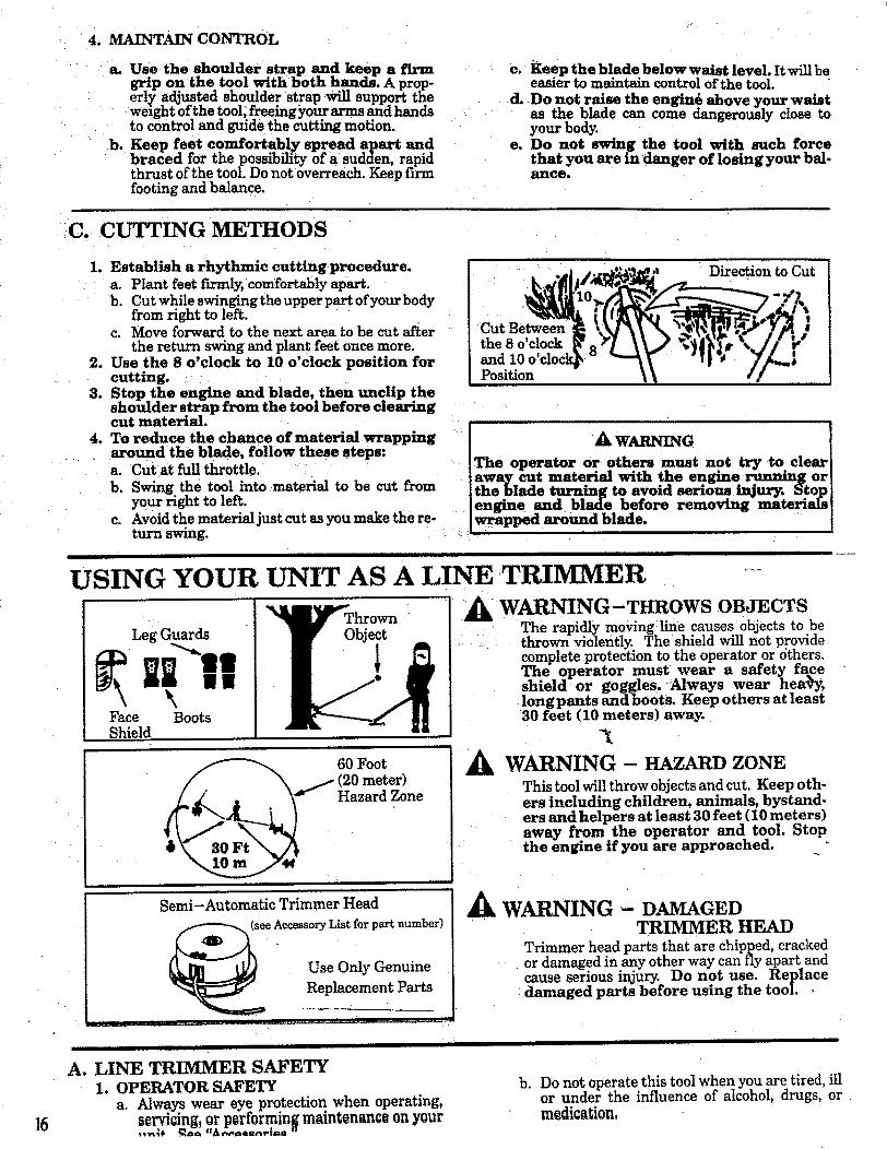
4. MAINTAIN CONTROL
a. Use the shoulder strap and keep a firmgri'p o.n _ne tool .with both h andL A prop-erly .adjustea snoulder strap will support theweightofthetool,free'mgyourarms and handstocontroland guidethecuttingmotion.
b. Keep feet c omi'ortabl_ spread apart andbraced for the possibility of a sudden, rapidthrust of the tool. Do not overreach. Keep firmfooting and balance.
C. CUTTING METHODS
c. E:e .ep the blade below waist level. It willbeearner to maintain control of the tool.
d. Do not raise the engind above your waistas the blade can come dangerously close toyour body.
e. Do not swing the tool with such forcethat you are in danger of losing your bal.anceo
?
1. Establish a rhythmic cutting procedure.a. Plant feet firmly, comfortably apart.b. Cut while swingingtheupperpart ofyourbody
from right to left.c. Move forward to the next area to be cut after
the return swing and plant feet once more.2. Use the 8 o'clock to 10 o'clock position for
cutting.
3. Stop the engine and_blade, then unclip thesnotuaer strap from the tool before clearingcut material.
4. To reduce the chance of material wrappingaround the blade, follow these steps:a. Cut at full throttle.b. Swing the toolintomaterialto be cut from
your righttoleft.
c. Avoidthe materialjustcutasyou make there-turn swing.
A, WARNING
Direction toCut
The operator or othe_m must not try to elemaway cut material with the engine running oxthe blade turning to avoid serious injur_ _to_engine and blade before removing materiahwrapped around blade.
i i
n i uu
__I 0 Foot(20meter)
Hazard Zone
Semi-Automatic Trimmer Head
(seeAccessoryListforpartnumber)
Use Only Genuine
Replacement Parts
A
A
I III Ill III II I Ilrll| II
A. LINE TRIMMER SAFETY1. OPERATOR SAFETY
a. Always wear eye protection, when operating,_rvi_ing,orp_rformingrnmntenanc_ on your
The operator must wear a safety faceshmld _or goggles. Always wear hea_y,longpants and boots. Keep others at least30 feet (10 meters) away.
WARNING - HAZARD ZONE
This tool will throw objects and cut. Keep oth-ers including children, animals, bystand-ers and helpers at least 30 feet (10 meters)away from the operator and tool. Stopthe engine if you are approached.
WARNING- DAMAGED• TRIMMER HEAD
Trimmer head parts that are chipped, crackedor damaged in any other way can fly apart andcause serious injury. Do not use. Replace
: damaged parts before using the tooL
I I II I i iluinnnnnn i
-i
b. Do not operate this tool when you are tired, illor under the influence of alcohol, drugs, or.medication,
Leg Guards "%__hrown WARNING-THROWS OBJECTS
elf Obj_ t
The rapidly movingline causes objects to bethrown violently. The shield will not providecomplete protection to the operator or 6thers.
USING YOUR UNIT AS A LINE TRIMMER ....

c. Always wear heavy, long pants, boots, andgloves. Do not go barefoot or wear sandals,
• short pants, jewelry, loose clothing, or clothingwith looselyhanging straps,ties,tassels,etc.;they can be caught in moving parts.Securehairsoitisabove shoulderlength:Beingfullycoveredwillhelp protectyou from piecesoftoxicplantssuch as poisonivythrown by theblade,which couldbe more of a hazard thantouchingtheplantitself.
d. Do not swing thetoolwithsuchforcethatyou 3.arein dangeroflosingyour balance.
e. Never startor run the engineinsidea closedroom or building.Breathingexhaust fumescan kill.
f. Keep handlesfreeofoiland fuel.
2. TOOL SAFETYa. Inspectthe entiretoolbeforeeach use. Re-
placedamaged parts.Check forfuelleaksandmake sure allfastenersare in placeand se-curelyfastened.
b. Use only.080"diameterSEARS LaserLine.Neverusewire,rope,string,etc.
c. Be surethe shieldisproperlyatta_ch_d,d. Make suretrimmer head isproperlyinstalled
and securelyfastened.Referto'7_ssembly.".............................H_ _H,,,_ _ HH,_,, II I lillIIIIIIIIIIIIIIIIIIIIIIIII
e. Be sure trimmer head stops turning when en-gine idles. See "Carburetor Adjustments."
fo Make carburetor adjustments with the driveshaft housing supported to prevent the trim-mer line from contacting any object.
g. Keep others away when making carburetor ad-justments. _/ ......
h. Use o_y accessories or attachments as recom-mended by Sears for2his tool.
CUTTING SAFETYa. Inspect the area to be cut before each use. Re-
move objects (rocks, broken glass, nails, wire,string, etc.) which can be thrown or become en-tangled in the trimmer head.
b. Always keep the engine on the right side ofyour body.
c. Hold the toolfirmlywithboth hands.d. Keep firmfootingand balance.Do not over-
reach.e. Keep thetrimmer head below waistlevel.f. Do not raisetheengineabove yourwaist.g. Keep allpartsofyourbody away fromthetrim-
mer lineand mufflerwhen engineisrunning.h. Use onlyforjobsexplainedinthismanual.
I IIII I II IIII
B. TRIMMER LINE ADVANCE
Q
O
The _trimmer line will advance approxi-mately 2 inches each time the bottom of thetrimmer head is tapped on the ground withthe engine running at full throttle.
The most efficient line length is the maxi-mum length allowed by the line limiter.
Always keep the shield in place when thetool is being operated. Figure 35.
To Advance Line:
1. Operate the engine at full throttle.
2. Hold the trimmer head parallel to and abovethe grassy area.
3. Tap bottom of trimmer head lightly on groun donetime. Approximately 2 inchesoflinewillbe advanced with eachtap.,..........__ -
Always tap trimmer head on a grassyarea.Tapping on surfacessuchasconcreteorasphaltcan cause excessivewear to the trim-mer head.
If the line is worn down to twoinches or less, more than one tap will be re-quired to obtain the most efficient line length.
A W_JtNING ...................Use only .080" diameter Scars Laser I,ine.-Oth_sizes_ offline-wrill not advance prope rlyLDonot use otl_er _naterials _ such as wire
Ak WARNING .... [Use minimum speed and do not crowd the line]when cutting around hard objects (rock, gravel, Ifence posts, etc), which can damage the trimmer ]head, become entangled in the line, or be]thrown causing a sermus hazard. " [
To Advance Line,Tap Bottom OfTrimmer Head On.Ground One Time.
ii
Line Limiter Cuts Line
C. CUTTING METHODS
• The tip of the linedoes the cutting, You willachievethe bestperformanceand minimum linewear by not crowding line into cutting areauThe .....right and wrong ways are shown in
• For trimming or sca/pir_, us€ less than fullthrottle to increase fine-life, especially:
- duringlightduty cutting.
- near objectsaround which the linecan wrapsuchas smallposts,treesorfencewire.
WRONG Work Area RIGHT The
I7

• "The line will easily remove grass and weedsfrom around walls, fences, trees and flowerbeds, but it also can cut the tender bark of
"Lrees or shrubs and scar fences. To help avoiddamage especially to delicate vegetation or treeswith tender bark, shorten line to 4-5 inches anduse at less than full throttle.
• Formowingorsweeping, usefull throttlefora good clean job.
3 Inches
Above :,_Ground,
Tip of the LineDoes the CUtting
SCALPING
18
I A WARNING j
Always wear eye protection. Never lean over the [trimmer head. Rocks or debris can ricochet or Jbe thrown into eyes and face and cause blind-[ness or other serious injury. I
1. TRIMMING - Hold bottom of thetrimmer head about 3 inches above ground and at
: an angle. Allow only the tip of the line to makeContact. Do not force trimmer line into work area.
2. SCALPING - The scalping tech-nique removes unwanted vegetation. Hold thebottom of the trimmer head about 3 inches abovethe ground and at an angle. Allow the tip of theline to strike ground around trees, posts, monu-ments, etc. This technique increases line wear.
3. MOWING- Your trimmer is idealfor mowing in places conventional lawn mowerscannot reach. In the mowing position, keep the
: ....line parallel to the ground. Avoid pressing thehead into the ground as this can scalp the groundand damage the tool.
4,: SWEEPING - The fanning actionof the rotatingline can be used for a quick and easyclean up. Keep the line parallel to and above sur-faces being swept and move tool from side to side.
ttttHItttltl I HIIIIIIIIIIII
D.LINE REPLACEMENT
• For proper line feed:
- Use only genuine S.F__S prewo_d_ooisand.080" diameter line. Use of other types ofspools or lines can result in excessive breakage,line welding, and improper line feed.
1,
- Pre-wound spools offerthe most conven-Ient method for replacing hne as well asoptimum performance.
Always clean dirt and debris from spool andhub When performing any type maintenance.Installing Spoolwith Line .............a. Hold the trimmer head as shown in _.
Press the lock tab and turn the lock ring1.
b. Remove the lock ring, tap button, and spool.
c. Clean dirt and debris from all parts.d. Inspect all trimmer head parts for damage. Re-
place damaged parts.
]Trimmer head parts that are chipped, cracked, IIbroken, or damaged m an_ other way can fly[[apart and cause serious injury. Do not use. Re-[Iplace damaged parts before using the tool. [
•" SWEEPING
Lugs
Drive Gear
C_ Lock Ring
Lock Ring Lock Tab
To Remove, Turn Lock Ring CounterclockwiseTo Replace, Tur__ L_k Ring Clockwise

The aluminum line saver can become_-worn during use. After a groove is worninto line saver, remove it from trimmez: head, turnit.upside down, and reinstall it (with" spool re-moved) to provide a new wear surface.
I A WAJaNmG [The line saver must be installed only from the in- Iside of the trimmer head. If installed on the out- Iside of the trimmer head, the line saver can fly[off and become a dangerous missile. .
e. Insert the end of the line through the line saver.Place spool in trimmer head. Press spooldown, then turn it enough to lock lugs onspool under lugs on drive gear.
Make sure the line is not caught betweenthe rim of spool and the wall of trimmer head.
f. Replace the tap button. Align the lock ringover the catches on the hub; push the lock ringdown on the hub and turn it clockwise until thecatches lock into place.
A W n'.TG [All catches must be fastened an.d the lock tab llatched in the Lock Ring. If Installed incor°rectly, the Lock Ring can fly off and become a]dangerous missile. ]
g. Make sure lock ring is properly fastened bypulling on it and trying to turn it counterclock'wise.: if it comes off, reinstallit properly.
h. Pull on the line to change the spool from thelocked position to the operating position.
i. Obtain the correct line length (4.-6 inches) bypressing the tap button and pulling on theline again.
NOTE: Each time the tap button is pressed, ap-proximately 2 inches of line can be pulled fromthe trimmer head.
2. SpoolReplacementa. Replace the spool when the square corners on
the lugs are rounded off, reduced in size, or bro-ken off.
b. To replace the spool, follow the instructions in' Installing Spool with Line."
3. Installing Line on SpoolTo replace the Line on existing Spool:
a, Follow "Installing Spool w/Line," steps"a.- d." and remove any line remmmng, onthe spool.
b. Use a40 foot length of.080" Sears Laser Line.
c. Insert 1/16" to 1/8" of the end of the linethrough the hole in the spool. •Allow no more than 1/8" Iine to extend in-side the spool.
d. Wrap the line onto the spool firmly andevenly in a clockwise direction as shown bythe arrow on the spool.
NOTE: The llne must be wrapped firmly andevenly for proper line feed.
e, Follow ':Installing Spool with Lin.e," steps"e i "
If the line breaks off or backs up in the trim-mer head, follow "Installing Snool' w/Line"steps a.-d. Pull slack m hne until the hne istightly wound on the spool, leaving 4-6 inches ofextended line. Continue with steps "e.-i."
Catch
Line Lock Tab
CatchCatch
Approximately 2 Inches of Line Can_,/Be Pulled From the Trimmer Head
Each Time the Tap Button is Pressed.
___ _,_..m-._ Lug
Ooo .t
For best results, use only .080"Sears Laser Line ® .
Wrap Line on Spoolas Shown by Arrpw
1/8"Line
4. Trouble Shooting the Trimmer Head and Line0 Does not advan0e/breakl while euttin$ i Welds onto spooh
- Improperly wound onto spool. - Line size incorrect.--hinesizeincorrect. - Incorrect8p0ol,- Too littlelineoutsidehead. - Crowding lineagainstmaterialbeingcut.
• Pulls back into head: Cuttingathigherspeedsthan necessary.- Too little line outside of head, .--
19

ii iiiii i ii i ]llllii II I IIII 1111111111TIJIII IIIIII III I I II I
ACCESSORIESi ii ii IIIIIINIWllllmIWIUWIIHIi Nil ii Hllm I
The following accessories are available through Sears
ITEM
In
Retail Stores, Catalog, Outlets or Service Centers.
STOCK NO.
Safety Face Shield ........... , ...................................................... 9-18613Safety Goggles......:...... ........................................................ 9-1859
2-Cycle Engine Oil ......... ,.. .................................................... 71-30143Spark Plug., ......... , ........................................................... 71-85854Replacement Weed BIade... .... ................................................... 71-85735Replacement Trimmer Head (available only through Sears Service Centers) ............... 952-701643Replacement .080" Dia. NylonTrimmer Line
400 ft ...... . .. !........ ........ .. ................. . ......................... 71-85778-- 200 ft.. ...................................................................... 71-85608
100 ft .............................................................. • .......... 71-85771
Replacement Spool with Line ....................................................... 71-85815Shoulder Strap Kit ............................................................... 71-85783Spark Arrestor Kit ............ ........ ,. ,_.............................. ......... 952-701612*Flex Shaft Lube ................................................................ 530-030102*
*Available through your SEARS SERVICE CENTER/CATAlOGUE.
I I Illlll Illllll IIIIIIIIIII III I II [ I II IIIII
NOTES
2O

iiii i ii i i ! i
CUSTOMER .RESPONSIBILITIESi i it t i t i i i t ill i iq i
A. _._ICE SAFETY
I. Maintain the tool according to recommended pro-
cedures. Keep the blade sharp and the cutting line at the pro-per length.
2, Never start the engine with the clutch shroud
removed. The clutch can fly apart and cause seriousinjury.
3. Disconnect the spark plug before performingmaintenance except for carburetor adjustments.
4. Make carburetor adjustments with the drive shaft hous-ing supported to prevent the blade or trimmer line fromcontacting any object. Hold the tool by hand; do not use theshoulder strap for support.
6. Be sure blade or trimmer head stops turning whenengine idles. See "Carburetor Adjustments.'"
7:. Wear protective gloves when handling or performingmaintenance on the blade.
. Throw away blades that are bent, warped, cracked,
broken, or damaged in any other way. Replace trim-mer head parts that are cracked, chipped, broken,or damaged in any other way beforeusing the tool.
9. Use only .080" diameter Sears Laser Line. Neveruse wire, rope, string, etc.
10. Use only genuine replacement parts as recommend-ed by Sears.
5. Keep others away when making carburetoradjustments.
II I I
B. _i, lg D_ $_ IJ/g_cJk'£1Ol_l• Lubricate the Flexible Drive Shaft:
- After each ten (10) hours of operation.- Before operating if the tool has been
stored for 90 days or longer.
When ordering flex shaft lube, See theAccessory:List for proper part number.
A WARNV G IIf engine has just been operated, avoid touching Ithe muffler. A hot muffler can cause serious[burns. I
Lay the flexible drive shaft on aclean surface. Avoid laying the shaft on thefloor, groun.d or on any other sttrface thatmay have dirt or debris. Even after wipingthe shaft, grease residue can pick up dirtparticles that can cause damage or prema-ture failure.
Take care to avoid injury to your-- h_a-d_ and fingers with broken wires when
checking for damage or wiping the flexibledrive shaft. A cloth will not prevent brokenwires from puncturing or tearing your skin.
!. Remove the gear box clamp screw and the Io- Ieating screw from the gear box.
2- Remove the gear box from the tube.3. Remove the flexible drive shaft from the tube.
4. Check flexible drive shaft for broken wires,twists or kinks, and replace if damage is found.
5. Using a clean cloth, wipe surface of flexibledrive shaft thoroughly to remove any grease.
[ •
11. InsPect the entire tool. Replace damaged parts. Checkfor fuel leaksand make sure all fasteners are in placeand securely fastened.
;, ; .......
6. Apply a uniform coat of lube to the entire sur-face of the flexible drive shaft.
7. Inject the remaining contents of the tube intothe top of the tube.
8. Replace flexible drive shaft in the tube.
9. Reassemble the gear box to the tube. Tightenscrews securely.
I
.!
21

ii ii i i i t ii iiiii
c. uazaxm, ; : ,, ........i -_:---:- follow the instructions. The basic carburetor settings _
[ AkWARNING ........ / are provided in the event they are required.
] Make_adjustmentswi'thtbedriveshaft_,:/ '_ ....... Turn the Low Speed Mixture Screw and the:High"ing supported to prevent the mane or trtmmer nne. " .... -.... I. .... . . .... ,.., ......... ,_ .._.._,,^_._;[ Speed Mixture Screw clockwtse untd they stop.
itromcomactmganyoojoet.rtotometomwzmyuurnmm,[ t3_, ,.,m t,,_, th .... _,,,_ until thin, are tieht as
]do not use theoptional shoulder strap for support. [ damage to'theneedle+seatscan occur, v" *"
_IbWAIII_ING b. Turn the Low Speed Mixture and High Speed Mix-' ture Sct:ews one full turn counterclockwise.
Keep others away when making carburetor• :: c. Follow instructions "a. Preparation,' through "f.adjustments. High Speed Mixture Adjustment.,
"_kWARNING
Serious injury to the operator and others can occurifthe
carburetor is not properly adjusted.:
• Poor engine performance can be a result of othercauses such as dirty air: filter, carbon build-up
on muffler outlets, etc. See "Trouble ShootingChart" before proceeding' with carburetor ...... :
:adjustments. ::$ The carburetor has been carefully adjusted at the *:+
factory. However, the operator must be sure that• : adjustments are made when any of the'conditions
occur as mentioned in "Trouble Shooting Sugges-
tions" below.
• Very small adjustments can affect engine perfor-mance. It is important to turn the screw a very smallamount _per adjustment and test performance beforemaking further adjustments. Each adjustment shouldbe no more than the width oflhe slot in the adjustingscrews.
• This is a complicated task. It is important to followinstructions in sequence as indicated.
1. TROUBLE SHOOTING SUGGESTIONS
-- Engine will not continue to run at idle position.See "b" Idle Speed Adjustment" and "e. Low
Speed Mixture Adjustment:'_ Blade or Trimmer Head continues to spin when
the engine idles. See"b. Idle Speed Adjustment"and "d. Deceleration Check:'
-- Engine dies or hesitates when it should accelerate.See "c. Acceleration Check"
-- Ia3ss ofcutting power which cannot be corrected
by cleaning the air f'dter. See "f. High Speed Mix-ture Adjustment"
-- Engine does not return to idle from full throttlewithin 2 seconds, See "d, Deceleration Check"
--Engine will not run. See "Trouble ShootingChart" Then, if'the carburetor requires adjust-.
ment, begin with"2. Basic Carburetor Settings:'
&WAaSISG ......IThe Blade or trimmer line will be spinning-dii-l:irigmost of this procedure. Wearyour protective equipment
.__d°bse_e all safety instru_ction.s. .....
-+2.BMIIC CARB_TOR |l_OllNOTE: In most cases, your engine can be made to
run properly with minor carburetor adjusunents.l_fer to "Trouble Shooting Suggestions" in the left
column for the condition you are experiencingand
a. PREPARATION
i.) Use a fresh fuel mix. See "Fueling Your Engine:' +2. iMake sure line extends tOthe length allowed by line
limiter to provide'correct load on engine.
3.)Start the engine. Cut grass for 3 minutes to warm
engine. The engine must be at operating temper-ature before carbt_retor adjustments can be per-formed correctly ,
4. )Stop engine and remove air filter by pulling it outwith your fingers. Refer to "Specifications" forlocation.
b. IDLE SPEED ADJTtJSTMENT
l.)Ailow engine to idle.
2.)Adjust Idle - Speed Screw until the:: enginecontinues to run •without stalling and .__without the trimmer head moving.-- Turnsc-_ clockwise to increase engine speed +
if the engine stalls or dies.
-- Turn screw counterclockwise to slow enginedown and/or to keep blade or trimmer head
from turning.
3.)Follow instructions]n "c. Acceleration Check'"and "d. Deceleration Check"
4.)N 9 furthei" adjustments are necessary if thetrimmer head does not turn at idle speed and
L if performance is satisfactory.
A WAmCmGRecheck idle speed after each adjustment. The blade ortrimmer head must not turn at idle speed to avoid serious
injury to the operator and others.
€. ACCELERATION CHECK
i.)Allow engine to idle.2,)$qu©cz¢ Trisger fully
a. If performance hsatisfactory, proceed to "d.Deceleration Check."
b. If the engine does not accelerate smoothly,
tum_e _LowSpeed MixtureScrew counter-clockwise a small amount (no more, thanthe
width of the slot in the adjusting screw).
3.)Repeat step "2.)" until smooth acceleration isobtained,NOTE: It may be necessary to repeat "b. Idle
Speed Adjustment" through "'c. AccelerationCheck :' to obtain correct adjustments.
<) Follow instructions in "d. Deceleration Check .'"

i
d. DECELERATION CHECK
1.) Allow engine to idle, then squeeze Throttle Trig-ger fully.
2:)Allow engine to run at full speed for about 1second.
3.iRelease the Throttle Trigger to the idle positionand listen to the deceleration of the engine. It mustreturn to idle smoothly and within I to 2 seconds.a. If performance is satisfactory,-proceed to
step "4.)"b. If the engine slowly or erratically returns to
idle or idles erratically, repeat"b. Idle Speed
Adjustment" or continue through Low SpeedMixture and High Speed Mixture Adjustments
4.)Set the _ Speed Mixture Screw at the mid--
point between the two positions._.:!: : = 5:)Follow instructions in "c. Acceleration Check"
• and "d, Deceleration Check"
f. HIGH SPEED MIXTURE ADJUSTMENT
[CAUTION:] Do not operate engine at full
throttle for prolonged periods while making high
: : : speed adjustments as damage to the enginecan occur.
1.) Support the drive shaft housing so the trimmerline is offthe ground and will not make contactwith any object.
2.)Al!ow engine to idle, then squeeze Throttle Trig-ger fully.
NOTE: Perform steps "3.)" through "5.),':at full throttle. ....... .
3.) Tum High speed, Mixture Screw veby slowlyclockwise until engine speed is reduced.
4, )'i_Jm--Hig--h-S_ed Mixiure Screw vdry _Io_iv---counterclockwise. Stop when the engine beginsto run roughly.
5.) Turn the screw slowly the minimum amount
clockwise until the engine runs smoothly.6.) Follow instructions in "c. Acceleration Check"
and "d, Deceleration Check:' i
!CAUTION:] If the engine does not operate
accordLng to these instructions after repeating
the adjusting steps, do not use the tool. Take' it to your Sears Service Center.
to obtain proper deceleration.4. )Recheck idle speed.
HIGH SPEED MIXTURE
IDLE SPEED AIRADJUSTMENT FILTERSCREW COVER
I
I
I.)Allow engine to idle.2, Turn the Low Speed Mixture Screw slowly ,I
..... Lclockwise until thespeed starts todrop. - /Note this position.
3:)Turn the Low Speed Mixture Screw counter------
clockwise until the speed increases and thenstarts to drop again. Note this position.
i1 i it II ] ]
D.. STARTER ROPE ...................................................
& t tNGra •Never start the engine with the clutch shroud removed.The clutch will fly apart and cause serious injury.
Ak WARNING
Do not remove the retaining tab and screw"to removepulley. The spring beneath the pulley is under teusion
and can fly out causing serious injury, ffany part of theput housingassemblyisdamagedotherthantherope,do not use the tool. Take it to your Sears Service Center.
I. Disconnect Spark Plug Wire. ,................2. Remove the Screw and Nut in the Throttle Trigger
Housing.HotdtheThrottleTrigger away from DrivelShaft Housing and remove Throttle Cable from i
Trigger. Pull Cable out of Foam Grip :_tunnel.
3, _rn_€ the fourClutch Shroud Screws_ shown inwiththesm ll wrenehprovided,
4. Separate theClutch Shroud fromthe Engine, L.
•& O Gml , [ !Use only a hand tool to remove the clutch, Do not use any
type of motorized tool or strike the clutch in any way. Other-
wise, the clutch wiU fly apart and cause serious injury.
g. REINSTALL AIR FILTER
Be sure filter is clean. Seeinstructions.
"Air Filter" for
]CAUTION: ] Fit air f'dter into the corners ofthe
housing to keep dirt from entering the engine andcausing engine damage.
If
H..... . L_ ' ......REMOVESCREWS € "FLATS"
:hownwithout Drive ShaftHousLngfor clarity.
7SHROUD_
| iii
23

5. Hold the "Flats" of the Clutch with an adjustablewrench as shown in Figures and remove the Nutcounterclockwise with a 9/16" socket wrench.
NOTE: Clutch will slide offthe crankshaft intact. Donot disassemble clutch.
6. Remove the Beveled Washer, Clutch and Large FlatWasher.
7. Remove the Pulley Housing from the Engine. •
8. Remove Rope Retainer Screw. Remove any
remaining rope.
:9.
4
10.
11.
12.
3,
I4.
Hand turn the Pulley clockwise asfar as it will go. Then,turn the Pulley counterclockwise until the PulleyNotch is aligned with the Housing Notch next to theRetaining Tab and Screw. Next, turn the Pulley onecomplete turn counterclockwise until the notches arealigned again.
Insert the smallhex wrench into the hole formed bythe Notches to hold the Pulley in position.
Use a 42 "length of replacement Rope.
Move away (10feet) from the fuel tank with the replace-ment Rope. Use a match and melt both ends of the Ropeto prevent fraying.
Pull the melted ends through a thick, clean rag whilethe Rope is still hot to obtain smooth, pointed ends.
Insert one end of the Rope through the Handle andsecure with a knot.
15. Insert the other end of the Rope through the Rope ExitHole into the inside of the Housing, into the Pulley andup through the Pulley Hole.
16. Wrap Rope counterclockwise around the Pulley Ratchetand tuck loose end under Rope where it comes out ofthe Pulley Hole. Leave a 1-inch tail laying flat on top ofthe Pulley between the Retainer Rib and the Rope Reten-tion Screw/Post.
17. Reinstall the Rope Retention Screw into the reten-
tion post. Tighten until snug.NOTE: Do not overtighten the Screw. Overtighteningthe screw can cause the threads in the screw postto strip out.
18. ltold Rope taut at Rope Exit Hole so it will not move andremove hex wrench.
19. Slowly feed rope into the Pulley Housing__ .....20. Make sure Spacer is in place as shown then reverse
steps to re-assemble.
ICAUTION:t When reinstallingtheclutch, tightenthe nut just until the beveled washer is flattened
against the clutch. Over or under tightening lhenutcan cause engine damage.
PULLEY HOUSING
CLUTCH
_"---- RopeRetainer Screw
Pulley
Washer
I"*---Rope Tail "
Screw Post
3110
RetainingTab andScrew
5/32" Hex_
RopeExitHole_:
Pulley
Pulloy.Ratchet
RetainerRib
Raised
Circle
HousingNotch

_ i i i i ii
_E. AIIt FIL11_A dirty air filter decreases the life and
performance of the engine and may increase fuelconsumption and harmful emissions.
1. Clean the Air Filter:• Always after 5 tanks of fuel or 5 hours of
operation, whichever is less.• Mor e frequently, in dusty conditions.
a. Loosen_hetwo screwson theairfiltercover
enough toremove thecoverfrom engine,b. Remove the airfilterfrom the cover,
c. Wash filterinsoapand water.d. Squeeze filterdry and replaceincover.
• C['-C'_UT_ Make sure the air filter is fittedinto the corners of the cover to keep dustfrom entering the engine and causing en-gine damage. ....
If replacing the air filter, see theAccessory List for proper part number.
Choke
._ AirFilter
so may create a fire hazard or produceharmful evaporative emissions.
e. Reinstall the air filter cover, making surethe choke exit slot is placed over the chokelever. :
i IF. BLADE SHARPEIqlI_G
A .....Always stop the engine before sharpening ablade: The blade will continue to spin after theengine stops or after the throttle trigger hasbeen released. Make sure the blade has stoppedcoasting and disconnect spark plug before per-forming work on blade. ..........
I. The blade is reversible, When the cutting edgeon one side becomes dull, turn the blade over.
...._When both sides!Of cutting edges become dull, theblade may be resharpenroened,. -
2. Check blades for flatness periodically. Laythe blade on a flat surface and inspect the blade forflatness before shArperdng. Throw away a bladethat is not fiat.
3/File or grind each edge in the same manner'tomaintain_abalancedblade.
A WARNING " 'Always replace a blade that is bent, warped,cracked, broken, or damaged in any other wa3_Never attempt to straighten and re-tree a dam-aged blade. Use only tee specified replacementblade.
AirFilter CornersCover
11 _ . _ IIII III
A WAR G ]To prevent the blade from cracking or flying[apart after sharpening, do not file within 1/4[
inch of the radii shown in Figure 26. I
File or Grind Each
Edge in the SameManner toMaintain
a BalancedBlade.
1/4Inch i f_._
Radi_
Maintain
Ar On]yWear protective gloves when
handling or performing maintenance onthe blade to help avoid injury.
.............. ................................
H u, t,umlull HI u II IHII III I
, ,, ,utr,tl
NOTES
T..
25

i i . i i i i, HIIIIIIIII I
Immediately prepare your unit for storage at the end of theseason or if it witl not be used for 30 days or more.
WARNING:ALLOW THE ENGINE TO COOL, AND SE-CURE THE UNIT BEFORE STORING ORTRANSPORTING IT IN A VEHICLE.
STORE UNIT AND FUEL IN AN AREAWHERE FUEL VAPORS CANNOT REACHSPARKS OR OPEN FLAMES FROM WA-TER HEATERS, ELECTRIC MOTORS ORSWITCHES, FURNACES, ETC.
STORE UNIT WITH ALL GUARDS INP LACE. POSITION SO THAT ANY SHARPOBJECT SUCH AS BLADES CANNOTACCIDENTLY CAUSE INJURY TO PASS-ERS BY.
STORE THE UNIT OUT OF THE REACHOFCHILDREN.
GAS TRIMMER/BRUSHCUTTER STORAGEINSTRUCTIONS
if your tdmmedbrushcutter is to be stored for a period oftime, clean it thoroughly prior to storage. Remove anydirt, sawdust, leaves, oil, grease, etc. Store in aclean dryarea.
0 ° Clean theentire unit.
Clean air filter. Refer to ,Customer Responsibilities".
Open the line head assembly and clean any dirt,grass ordebris that has collected. Inspect the cutting line, if old(chalky look and sticky to the touch), remove and dis-card. Install fresh new line the next time product is to beused.
Lightly oil external metal surfaces to prevent rust fromforming.
- AUTION: Wear protective gloves whenhandling blade. The blade is sharp andcan cut you even when it is not moving.
If your unit is equipped with a blade, remove it from theunit. Refer to "Assembly". Apply a coating of oil to theentire surface of the blade and wrap it in heavy paper,cloth, or plastic. Also apply a lightcoat of oilto gear hous-ing threads, then tighten blade nut securely for storage.
Reassemble all loose parts, being sure that all handlesandgu=rdsareinp!a_eandaresecurelyfastened,Ra-pla0eanydamagedparts.
ENGINE
Never use engine orcarburetor cleaner products in the fueltank or permanent damage may occur to fuel system com-ponents,
Follow these instructions:a. Drain the fuel from the unit into an approved
fuel container.b. Drain the fuel lines and carburetor by starting
the engine and letting it run until it stops.c. Allow the engine to cool before storage.
IMPORTANT: It is important to prevent gum deposits from'forming in essential fuel system parts such as the carbure-tor, fuel filter, fuel I{ne or tank during storage. Also, experi-ence indicates that alcohol blended fuels, those that useethanol or methanol (called gasohol or oxygenated fuel),can attract moisture and form acidic gas which will damageyour engine. To avoid engine problems, the fuel =systemshould be emptied before storage of 30 days or longer.
NOTE: Fuel stabilizer is an acceptable alternative in mini-mizing the formation of fuel gum deposits during storage.Add stabilizer to the gasoline in the fuel tank or fuel storagecontainer. Always follow the mix instructions found onstabi-lizer container. Run engine at least 5 minutes after addingstabilizer to allow the stabilizer to reach the carburetor.
NOTE." Craftsman 40:1 2-cycle engine oil is speciallyblended with fuel stabilizers. If you do not use this SEARSoil,you can add a fuel stabilizer (such as Craftsman #33500)to your fuel tank.
• Remove spark plug and pour I teaspoon of 40:1 oil mixthrough the spark plug opening. ,Slowly pul! the starterrope 8 to 10 times to distribute oil to inner engine sur-faces.
• Replace spark plug with a new one of the recommendedtype and heat range, Refer to "Product Specifications".
• Clean air filter. Refer to."Customer Respo_n_sibilities".
• Reinstall all covers_nd hardware removed for access;tighten al! screws arrcl fasteners.
• Check entire unit for loose screws, nuts, and bolts. Re-place any damaged, broken, or worn parts.
• Use fresh fuel having the proper gasoline to oil ratio at thebeginning of the next season.
OTHER• Do not store gasoline from one season to another.
• Replace your gasoline can ifyour can starts to rust. Rustand/or dirt in your fuel system will cause problems.
• Store your unit in a welt ventilated area and covered, ifpossible, to prevent dust and dirt accumulation. Do notcover with plastic. Plastic cannot breathe and will inducecondensationand eventualrustorcorms!on.
[M.P_QJ_T._!_ Never cover unit while engine and exhdustareasarestillwarm,
26

TROUBLE SHOOTING
SYMPTOM
start or will runonly for a fewseconds afterStarting.
Engine will notidle properly.
Engine will notaccelerate,lackspower, or diesunder a load.
Enginesmokesexcessively.
Engine runs hot.
Cutting Head stopsunder a load ordoes not turnwhen engine isaccelerated: :
i i,J JL
Line doesnotadvance or breakswhile cutting. _ _ :
i,,.
Line welds on spool.
Line releasescontinuously.
Line usage isexcesslve.
Line pulls backinto head.
.
4.5.6.
1.
CAUSE _ •II, II
1. Fueltank empty.2. Engine flooded.
Spark p!ugnot firing.Fuelnot reachingcarburetor.Carburetorrequiresadjustment.None oftheabove.
Carburetor requires adjustment2. None of the aboVe.
1. Air filter dirty,2, Spark plug fouled.3. Carburetor requires adjustment,4. Muffler outlets plugged,
.
5.6.
| ,,,,,,,,,,
1.2.
REMEDY,, .,, ==
1, Fill tank with correct fue! mixture
2, See "Starting Instructions."3. Install new plug/check ignition system,
Clean fuel filter; inspect fue! line.See "Carburetor Adjustments."Contact yovr Sears Service Center/Dept,
See "Carburetor Adjustments,"Contact your Sears Service Center/Dept,
, ,,..,., ,,,,, ......... • ,....
1. Clean'or replace air filter.2. Clean or replace spark plug and re-gap.3. See "Carburetor Adjustments."4. Contact your Sears Service Center/Dept.
5_
........ , ....... ,,,,, ,,, ....
1. Air filter dirty.2. Fuel mixture incorrect.3, Carburetor requires adjustment.
.
2.3.4.
.
None of the above. 5. i Contact y0ur Sears Service Center/Dept,
Fuel mixture incorrect. 1.Carburetor requires :adjustment. 2.Spark plug incorrect. 3.None of the above. 4.
.................... p ....
Drive shaft broken. 1,2. Drive shaft not engaged.
,, ,, i,,,i,,,,,,,,,,,,,,,,,,,,i,,,
i. Lineimproperlyroutedinhead.2. Lineimproperlywound ontospool.3. Linesizeincorrect.
4. Too little line outside head.5. Dirt accumulated on cover cut-outs.
...... ,.,,, ill IIMH
1. Line size incorrect.
2. Crowding lineagainstmaterialbeing cut.
3. Cuttingathigherspeedthan necessary., = ..................... ,,,,m
I. Tap Button engaged.2. Tap buttonknocked out ofhub.
..............................._ ,,L
I. Linesizeincorrect.
Cuttingathigh speed around hard objects.
Crowding lineagainstmaterialbeingcut.
Too littlelineoutsideofhead.
, i............
1. Clean or replace air filter.2. See "Fueling Your Unit."3. See "Carburetor Adjustments,"
See "Fueling Your Unit."See "Carburetor Adjustments."Replace with correct plug.Contact your Sears Service Center/Dept.
i,,,,u,,,,,,
Replace drive shaft.2.. See "Assembly".
.
3,, ,,± i1,,i,,1,
@
i. Remove coven Check linerouting.2. Rewind linetightlyand evenly.3. Use only.080"(2ram)diameterSearsLaser
Line.
4. Remove cover.Pull4,'oflinetooutside._5. Clean covercut-outs.
,HH .... '"'........
1. Use only.080"(2ram)diameterSearsLaser
Line. -_2. Cut witht_ of line.3. Reduce cutting speed.
1. Remove and clean Tap Button.'- -2. See "Installing Spool w/Line."
1, Use only .080" (2mm) diameter Sears LaserLine.
2. Reduce speedaround hard objects.
3. Cut withtipofline.
• Remove cover.Pull4" (10cm) oflinetooutside.
27

t dd tim, t,, t ,tl , ttmt ,,,,,, ,uoit ,,,it I __i_,,,,................it , tt ,,, ,,,, ....................................
III illliililllllllllllllllllllllllil . .mm i...........
LUBRICATIONADJUSTMENTS Engine ........................................................................... 11
Handlebar ............................................................................. 7 Flexible Drive Shaft ...................................................... 2ICarburetor .......................................................................... 22 MAINTENANCEIA ne Advance ..................................... _............................... 17Module Air Gap ................................................................... 2Spark Plug Gap .................................................................... 2Shoulder Strap .................................................................... 10Throttle Cable ...................................................................... 7
AIR FILTER ............................................................................. 25ASSEM B i,¥
Blade .................................................................................... 9
Clamp, Shoulder Strap ....................................................... 10Handlebar ............................................................................. 7Preparation ........................................................................... 6Shield
Line Trimmer ............... _.................................................... 8
Air Filter .................. _.................................................... 25Blade, Weed .................................................................. 25Carburetor ..................................................................... 22Flexible Drive Shaft ...................................................... 21Safety ............................................................................ 21StarterRope...:.............................................................:..........23Triromer Head ............................................................... 19Trouble Shooting Chart ................................................. 26
MODULE AIR GAP.L ...... :.................................................. 2OIL, ENGINE
Ratio to Gasoline ........................................................... I 1Types to Use; not_o Use ............................................... I 1
OPERATIONWeed Blade ....................................................................... 9
Shoulder Strap ......................................................... ........... 10Throttle Cable ...................................................................... 7Trimmer Head ...................................................................... 8Weed Blade .......................................................................... 9
!1LADE, WEED
Cutting Methods ................................................................. 14Guard Against Blade Thrust .............................................. 15Maimcnaace ....................................................................... 25
Safety ................................................................................. 2 ISharpening ......................................................................... 25
CARBURETOR ADJUSTMENTS ........................................ 22CARTON CONTENTS ............................................................. 5COLD ENGINE STARTING .................................................. 12
Advancing the Line ....................................................... 17Mowing ......................................................................... 18Pre-Operation Cheeks ................... ; ............................... 12Position ......................................................................... 10Safety
Blade .......................................................................... 15Line Tdmmer ............................................................. 17
Scalping ........................................................................ 18Starting the Engine ........................................................ 12Speed ............................................................................. 13Stopping the Engine ...................................................... 12Sweeping ....................................................................... 18Trimming ...................................................................... 18Weed Btade ................................................................... 16
CONTROI,S ............................................................................... 2CUTTING METHODS
Weed Blade ........................................................................ 16Line Trimmer ..................................................................... 18
DRIVE SHAFT HOUSING ASSEMBLY ................................ 6ENGINE
Air Filter ............................................................................. 25Carburetor .......................................................................... 22Controls ................................................................................ 2Fuel Mixture ....................................................................... 1iStarter Rope ....................................................................... 23Starting Instructions ........................................................... !2Storage ................................................................................. 4Trouble Shooting ................................................................ 26
ENGINE OILRatio to Gasoline ................................................................ I ITypes to Use; not to Use .................................................... 1l
FILTER, AIR ............................................................................ 25FI.EXIBI,E DRIVE SHAFT LUBRICATION ...................... 21FUEl,
GasolinetOil Mixture ......................................................... 11Mixing Fuel ........................................................................ 11Pouring Fuel ....................................................................... 1!Safety ................................................................................. 11Storage ............................................................................... 11
GASOLINERatio to Oil ......................................................................... 11Type to Use; not to Use...................................................... 11
IDLE SPEED ADJUSTMENT ............................................... 22LINE
Advance ............................................................................. 1?Breaking ............................................................................. 20Length
Operation ......................................................................... 19To Cut as Replacement ................................................... 20
Replacement ....................................................................... 19I(c\viudilt_ un Sl_t_l ........................................................... 20Routing hi Head................................................................. 19Safety ................................................................................. 19Size to Use ......................................................................... I9"l'rt_ubl¢Shta_ting ................................................................ 20Wekling Ohio Spool ............................................................ 20
PARTS LIST ....................................................................... 27PRE-OPERATION CHECKS ........................................... 12PREWOUND SPOOLS ..._................................................. t 9REPAIR PARTS LIST ....................................................... 27 -SAFETY INSTRUCTIONS, WARNINGS .................. 3 & 4SHIELD
Line Trimmer Assembly ................................................. 8Blade Assembly .............................................................. 9
SHOULDER STRAP CLAMP ASSEMBLY ................... I0SHOULDER STRAP ......................................................... 10SPARK PLUG GAP ............................................................. 2SPARK ARRESTOR .................................... _................. w.,.5SPECIFICATIONS .............................................................. 2SPOOL
Installation ............ ........................................................ 19Maintenance..._ ............................................................ 19Prewound ...... ..?:............................................................ 19Rewinding ..................................................................... 20
STARTER ROPE REPLACEMENT ............................... 23STARTING INSTRUCTIONS .......................................... t2STORAGE ............................................................................. 4THROTTLE CABLE ASSEMBLY .................................... 7TRIMMER HEAD
Assembly ....................................................................... .8Line Routing ................................................................ 19Maintenance .................................................................. 19Removal ........................................................................ 19Safety ............................................................................ 17Shield .............................................................................. 8
TROUBLE SHOOTING CHART ................................. 26USING YOUR TOOL AS A WEED CUTTER ............... 14USING YOUR TOOL AS A LINE TRIMMER .............. t6WARM ENGINE STARTING ........................................... 12WARM ENGINE STARTING AFTER RUNNING
OUT OF FUEL .................................... . ....................... 12WARNINGS AND SAFETY INSTRUCTIONS ......... 3 & 4WARRANTY ........................................................................2WEED BLADE ASSEMBLY .............................................. 9
Operator'sManual
Model No.358.798260-32cc
How to OrderRepa_ Parts
SEARS SERVICE
IS AT YOUR SERVICE
The ModelNumber will be found below the top handle with the SerialNumber. Always mention the Model Number when requesting service orre'pal"r parts for your trait.
All parts listed herein may be Ordered from any Sears Service Centerand most Sears Stores.
WHEN ORDERING REPAIR PARTS ALWAYS GIVE THE FOLLOWINGINFORMATION AS SHOWN IN THISLIST:
i. The PART NUMBER 3. The PART DESCRIPTION
2. The MODEL I/UMBER 4. The NAME OF ITEM --
358.798260 - 32cc Gas Weedwacker _
If the parts you need are not Stocked locally, your order will be trans-mitted to a Sears Repair Parts Distribution Center for handling.
When you buy merchandise fromSears you get an extra value thatnobody else can offer k SearsService.
Across town or across the country,Sears Service is always near,, pro-riding trustworthy, competentservice technicians using onlySears specified factory parts.
Your Sears Merchandise takes on added value when you discover ....
that Sears has Service Units through_t the country. Each isstaffed by Sears-Trained, professional technicians using Sears ap-proved methods.
Sears,RoebuckandCo,,HoffmanEstates,1L60179U.S,A,r ,llll ................ i liHll i r. i ,j
PRINTED IN U.S.A.

ESTE MANUAL ES MUY IMPORTANTE No lo tire a la basura
Manual del
operario
MODELO NO.
358.798260-32cc
Ax PELIGRO:
Lea el manual del operario ysiga todas tas advertencias einstrucciones de seguridad y las
instrucciones para ta
operacidn. El no hacerto puedecausarle lesiones graves.
Use siempre protecci6n para los ojos
SF_/AJ S/ gRRi:TSMRN®CORTADORA DE HIERBAS
WEEDWACKER _ A GASOLiNA DE 32cc
Motor de 2 tiempos
• Armado
• Operacidn
Mezcla de combustible 40: l
• Mantenimiento
• Piezas de repuesto
Ill _ FII............................ I II II I ...............................................
Sea?s, Roebuck and Co., Hoffman Estates, IL. 60179 EE.UU.
I I.IIIl.ll I I ||.llllll I III lllllllll IIIIllullll..llll
© 1994 Sears,Roebuck & Co.530-082426-1 _)4112/94 --

_11111 ' " . i • • • •• •1 • ' i iJi i 1
GARANTIA L1MiTADA DE DOS ANOS PARA LA CORTADORA DE HIERBAS "WEEDWACKER TM''CRAFTSMAN
PoT dos afios desde la fecha de la compra, si esta weedwacker TM es mantenida, lubricada y afinada de acuerdo COnlas instrucciones parala operacidn y el mantenimiento contenidos en el manual del operario, Sears reparar_, libre de cargo cualquier defecto en materiales omano de obra.
Esta garantfa excluye la Ifnea de nylon, la bujfa y el filtro de aire que son piezas reemplazables y se gastan durante el uso normal.
Si esta Weedwacker TM es empleada para usos comerciales o para alquiler, esta garantfa no se aplica.
EL SERVICIO DE GARANTIA ESTA DISPONIBLE PONIENDOSE EN CONTACTO CON EL CENTRO O DEPARTAMENTO DE
SERVICIO SEARS MAS CERCANO ENLOS ESTADOS UNIDOS. Estagarantfa se aplica solamente mientras este producto est,'i enuso cn los Estados Unidos.
Esta garantfa tc da a ustcd dcrcclaos legalcs especfficos y usted puede tenet otros derechos que varfan de estado a estado.
SEARS, ROEBUCK AND COJDEPT, D/817WA, HOFFMAN ESTATES, IL 60179 EE.UU.
LISTA DE CONTENIDOADVERTENCIAS E INSTRUCCIONES
PARA LA SEGURIDAD ...................................................... 3CONOZCA SU IIERRAMIENTA ............................................... 5ARMADO ....................................................................................... 6CARGANDO COMBUSTIBLE A SU MOTOR ........................ l I
ARRANCANDO SU MOTOR ..................................................... 12
USANDO SU CORTADORA DE MATORRALES .................. 14
USANDO SU CORTADORACOMO CORTADORA DE LINEA ..................................... I6
ACCESORIOS ;....: .............. :...:..:.,: .............................................. 20
RESPONSABILIDADES DEL OPERARIO ............................. 2 IINDICE .......................................................................................... 31 .....
ESPECIFICACIONES
TIPODE MOTOR 2 tiemLr,_s,enfriadopoTaire
En vacfo: 2800- 3200
Si CRONIZAClON...... A .cc hi p;i---DEL ENCENDIDO No ajustable ....
CARBURADOR Diafragma. Tnd,'t_las posicinnes consurtidores de mezcla de combustible
OT R regulables"APAGADO"DEL M O Bot6n para empujar _ •
ARRANCADOR Recnmllado automliticoSILENCIADOK Limitador de temperatura (sin
parachispiLs;yea NOTA en la pfigina6)EMBRAGUE Centfffug0 ...............TANOUEDECOMBUSTIBLE " 17oz. Ifqui_ .....
LARGO DEL _E 5 I"(129,5 cm) ,. ..........
BUJIA 71-85854 (CJ- lff)
ABERTURA DE LA BUJIA 0.025"
ABERTURA DEL 0.0 t010.014MODULO DE AIRE
LUBRICACIO N ................... Mezc!:t t!e g_ts_?litlay ace|re at 40:1)LINEAt ARA EL CORTE Seat_ !_lser Li,_e",difimetro 0.080"
HOJA Hoja pat hierbas de 4 puntos, 8"
NOTAt LASERLINE:" ES UNA MARCADE FAItRICAREGISTRADA DE WHITE CONSOIJDATED INDUSTRIES, INC.
FAltRICADA 8AJO [ !NA 0 MAS DE I.AS SIGUIF.NT[:S PATFNTt:S U, S,: 4JB5,912:4.1|52,78_: 4. I 12.653:4.1 hi ,_2o: 4,167.812:4.183,138: ,4.t 1_0,833:4.211,0(M: 4.286.675:
4.362.074:4.45 t.983; 4,798,185; 4,823A65; 4.841.929: 4.940.028: 5.020.223: y D324,051.
2 ESTAN PENI)I|'NTt-S OTRAS PA'F|:NTF.S U.S. Y DEL EXTERIOR•
Asa en "T" de la cuerda
para arrancar _r!l'_ Correa para el hombro '
lnterr uptoi_'_t_',,_embrague/ /9 "
" .-/_'__ Jk _// Manubr_o
/_"_spuma G_altil-lodei_ Etiqueta de seguridad
Ntimero de Serie e X_ _/ _. • "_'K
instrucdones para arrancar _-_7_:_ E_ud ° _/ ___/___ ..- met_ilico - "I1
•Tapa de combustible de la linea la cortadora
/N_ Hoia para hier
con 4 dientes
Estrangulador Cubierta delfiltro de airc
I|o 81!_.n_iutl0ry
para cebarsilenciador
la

ADVERTENCIAS E INSTRUCCIONES PAPA SEGURIDAD(Lea las instrucciones para seguridad adicionales a trav_s de este manual)
_, ADVERTENCIA: tESTA HERRAMIENTA MOTORIZADA PUEDE SER PELIGROSA[ Estahcrramienta puede eausar lesiones graves a los operarlos u otras personas, incluyendo amputaciones'_-ceguera. Lasadverteneias e instrucciones para la seguridad en este manual deben ser seguidas para proveer una seguridad razonable yelicienei'a eu el uso de esta herramienta. El operario es responsable de seguir las advertencias e instrueciones contenidas en estemanual yen la herramienta, iLea fntegrameate el Manual del Operario antes de. armar y usar esta herramienta! Restrinja el uso deesta herramienta motorizada alas personas que puedan leer, entender y seguir ias advertencias e instrucciones contcnidas en estemam, al ycn ta herramienta.
i Objeto
Proteetores para disparado
las piernas
Mdscara para Botasel rostro
Zona de peligrode 60 pies
(20 metros)
Manual d_loperarlo
1_.4HOJA PUEDE REBOTAR VIOLENTAMEArTE DEL
MATERIAL QUE NO PUEDA CORTAR.
--LA HOJA CIRCULAR DE SIERRA PUEDE• REBOTAR Y CAUSAR LA AMPUTACION DE
PIERNAS O BRAZOS.
--MAWFENGA A LA GENTE Y ANIMALESALEJADOS A 30 PIES (10 n0 DE DISTANCIA.
A ADVERTENCIA
LA LINEA DE I_.4 CORTADORA PUEDE DISPARAR
OBJETOS VIOLENTAMENTE.
--USTED PUEDE QUEDAR CIEGO O LESIONADO.
--USE PROTECCION PARA LOS OJOS Y LASPIERNAS.
de la hoja
aXADVERTENCIA
ZONA DE PELIGRO POR OBJETOS DISPARADOS.
--LA HOJA O LA LINEA DE LA CORTADORAPUEDE DISPARAR OBJETOS
VIOLENTAMENTE.
---OTRAS PERSONAS PUEDEN SER CEGADAS OLESIONADAS.
--MANTENGA ALEJADAS ALAs PERSONAS Y_,
AN1MALES A UNA DISTANCIA DE 30 PIES
( 10 METROS).
Detenga el desplazamiento dela hoja mediante el contacto
con el material cortado
Elhluglapainla seguridad
AADVERTENCIA X.
LA HOJA SE DESPLAZA CUANDO SE DESCONECTA EL
A CELERADOR.
--LA HOJA PUEDE CAUSARLE CORTES GRAVESA USTED Y A OTRAS PERSONAS.
_DETENGA LA HOJA CON EL MATERIAL
CORTADO.
A[_ADVERTENCIA
LEA EL MANUAL DEL OPERARIO.
--SIGA TODAS LAS ADVERTENCIAS EINSTRUCCIONES.
_EL NO HACERLO PUEDE RESULTAR EN
LESIONES GRAVES.

ADVERTENCIAS E INSTRUCCIONESPARA LA SEGURiDAD (Cont')"__IL SEGURIDAD DEL OPERARIO " ................. ServicioAutorizado.
• Use siempre protecci6n de seguridad para sus ojos, ' Zk SEGURIDAD PARA EL COMBUSTIBLE• Use sicmpre pantalones largos, gmesos, botas, mangas largas y :, Mezcle y vierta el combustible en el exterior ....
guantes. Se rcconficnda el uso de protectores para las piemas.No caminc dcscalzo ni use sandalias, joyen'a, pantalones cortos,rn;ingas cortas, ropa suetta, nl ropa con corbatas, eorreas,volados, etc. sueffos, ya quesc puedcn Irabar cn la eortadora. Etestar totahnentc cubierto ayudar_ a protcgerlo de pedazos deplantas t6xicas, talcs como la hiedra vcncnosa, impulsados pot la
hoja de la cortadbnl, quc poddan set m,SSpeligros0s que el tocarla planta misma,
* Asegure su cabetlo para q0e quede sobre sus hombros.. No ope_,eesta herramienta cuando usted est_icansado, enfermo o
bajo ta influencia del,alcohol, drogas, o medicinas. Useprotecci6n para los ofdos si va a utilizar launidad por m_s de I y1/2 horas por dia. .....Nunca arranque o haga funcionat el motor dentro de un armario,cuarto o edificio. El mspirar los gases del escape pueden matarlo.
- Mantenga los mangos libres deaceite y combustible,• Use siempre et mango de sujeci6n y una correa para el hombro
.debidamente ajustada, Vea "Arnaado".dX SEGURIDAD Y MANTENIMIENTO PARA LA
HERRAMIENTA* Inspeccione la herramienta antes de cada Uso y reemplace las
piezas dafiadas. Revise por fugas de combustible antes de cadauso. Mantenga la unidad en buen esgldo de funeionamienm.
, Descarte las hojas qt, e estfin torcidas,'combadas, rajadas odafiadas en cualquicr otra forma, Reemplace las piezas de lacabeza de ta cortadora que estdn rajadas, astilladas, rotas odafiadas en cualquier otra tbrma antes de usar la herramienta.
- Mantenga la unidad de acuerdo a los procedimientosrecomendados. Mantenga Ia hoja afilada. Mantenga la lfnea paracortar al largo apropiado.
- Use solamente la lfnea "Sears Laser Line" de .080" de difimetro.Nunca use alambre, soga. cord6n, etc.
- lnstale en, Ibrma apropiada el escudo requerido antes de usar launidad. Use el escudo de metal para cualquier aplicaci6n decorte co n h0jas. Use el escudo de plfis!ico para toda aplicaci6ntic colic c0ti Ifnc'a. : '
Use solamente la hoja o ta cabeza especificada para la cortadora;asegtlrese que est_i instalada en forma apropiada y ajustada.Nunca arranque el motor sin la cubierta del embrague en sulugar. El embrague puede salir disparado y causar heridasgraves,
- Asegfirese que Ia hoja o la cabeza de la c0rtadora se detienecuando el motor funciona en vaefo,
- Desconecte la bujfa antes de Itevar a cabo una tarea de
o .
,: Mantdngase alejado de chispas y llamas.• Use un reclpiente aprobado para el'combustible.• No filme ni perrnita que se fume cerca del combustible o de la
unidad o mientras se estd usando la unidad.• Limpie todo derrame de combustible antes de arrancar €l motor., Al6je_se lYorlo menos 10 pies (3 metros) del lugar donde se calg6
la gasolina antes de arranear el motor.Detenga el motor antes de sacar ia tapa del tanque decombustible.
• Agote el combustible del tanque antes de guardar ta herramlenta.
Consuma el combustible que queda en el carbumdor an'ancandoel motor y dejfindolo funcionar hasta que pare por sf solo.
• Guarde ta herramienta y el combustible en un _irea donde losvapors del combustible no puedan atcanzar a _hfspas o llamas
_ . abiertas de calentadores de agua, motores o interruptores__ el6ctricos, hornos, etc.
_, SEGURIDAD PARA EL CORTE....• inspeccione el firea que va a cortar antes de cada uso. Quite
• objetos (piedras, vidrios rotos, clavos; alambre, cuerdas, etc.) que: puedan ser disparados o que puedan enredarse en la hoja o en lacabeza de la cortadora.
• Mantenga.a otros incluyendo a nifios, animales, observadores yayudantes fuera de la Zona de Peligro de 60 pies (20 metros).Pare el motor inmediatamente si alguien se le acerca.
• Mantenga siempre el motor en eI lado derecho de su cuerpo.° Sujete la herramienta firmemente con ambas manos.• Mantenga los pies firmes y su equilibfio. No extienda demasiado
los brazos.• Mantenga la cabeza de la cortadora debajo del nivel de la
cintura.
° No levante el motor pot encima de la altura de su cintura.• Mantenga todas tas partes de su cuerpo alejadas de la hoja o de
la cabeza de la cortadora y del silenciador cuando et motor est_ien funcionamiento.
° Corte desde la derecha hacia la izquierda.• :.Use su tmidad solamente pare Ins trabajos expticados en este
manual._IX TRANSPORTE Y ALMA CENAMIENTO ,
° Detenga el motor antes de Ilevar la unidad de un lugar a otto.° Mantenga el silenciador alejado de su cuerpo. _ -• Deje que el motor se enfrfe y asegure la unidad antes de
guardarla o transportarla en un Vehfculo.• Antes de guardar o transportar la unidad, vacfe el tanque de
combustible. Consun_ el combustible que queda en las lfneas ymantenimiento (excepto cuando se regula el carburador).
° Haga la regulaci6n det carburador con la cubierta del eje de
propulsi6n apoyada para evitar que la hoja o la lfnea de ta:cortadora entre en contacto con cualquier objet0: Sujete taherranfienta con la mann; no use la eorrea opcional paraelhombro panl sujctar!a.
• Alejc a otras personas cuando esui haciendo la regulaci6n delcarburador
• Use solamente accesorios genuinos que son los recomendadospor Sears para esta hewamienta.
- Cuakluier mantenimiento o servicio que no ha sido explicado encste manuel se debt Ilevar a cabo por un Concesionario de
el carburador arrancando el motor y dejando que funcione hastaque se pare por sf solo.
• Guarde Ia unidad y el combustible en un _l,ea donde los vaporesdel combustible no puedan alcanzar chispas o llamas abiertas decalentadores de agua, motores o inten'upt0res eldctricos, hornos.etc.
• Guarde la unidad de tal manera que la hoja o el limitador de "lalfnea no pueda causar lesiones accidentalmente. La unidad pu_,deser colgada del soporte que tiene debajo del motor o por lacubierta det eje de propulsi6n.
• Guarde la herramienta fuera del alcance de los nifios.
Si ocurren situaciones que no esMn cubiertas en este manual, tenga cuidado y use buen juicio.Consulte con stt Departamento o Cetttro de Servicio si necesita ayuda.
TELEFONO DE EMERGENCIA PARA AYUDA A LOS CLIENTES: 1.800-235-5878
• AVISO DE SEGURIDAD
l,_ €¢,hqtNcifina hts vibraciones debid_ al uso prolongado de herramienti_8manuales a motor de gasolinn podria cattsar dafios a lost | I I | I It 1 I _ 11 | Itn_tvlo_tl_10_d_do_, la_nlan0s y ht_tttufi_a_d_ plt_0ltttssu_e_!tllbl_a enl'mttMatlo_deeulal0das o hhtdlitZOnt,._an0r'llltde._,I,;1u._.
prolongado de tales herramientas en tiempo frfo ha sido atribuido eomo la eausa de dafios a los vasos sanguineos en personas pot 1odenr, k_saludables. Si se presentan sfntomas eomo adormeeimiento, dolor_ p_rdida de fuerza, cambio en la ¢oloracidn de la piel o de sutextura o p_rdida de la sertsibiUdad en los dedos, las manos o las mufieeas, d|scontimie el uso de esta herramienta y lmsque atenci6nm_d|ca. Un sistema anti-vibratnrio no garantiza el evitar estos problemas. Los usuarios que operan herramientas motorizttdas enforma continua y regula r deben observar cuidadosamente sus ¢ondiei6n ffsiea y el estado de esta herramienta.

CONOZCA SU HERRAMIENTA
A_
B_
INTRODUCCIONSu cortadora Weedwacke( r'_ es un producto de alta calidad yestfi disefiada para tareas pesadas. Su versatilidad le ayudar_i allevar a cabo con facilidad una variedad de tareas.
Las caracter/sticas especiales incluyen:
• iloja reversible de cuatro puntas para pasto, yerba ymalon'alcs de hasta I/2" (13 ram) de difimelro.
• Cabeza con alimentaci6n automfitica de la ffnea para
podar, conar, barfer y para cortar al ras.
INSTRUCCIONES PARA DESEMPACAR
I. Saque el conlenido de la caja si lodavfa no Io ha hecho.
2. Compruebe tas piezas t:ontra latista que sigue.3. Examine Ins piezas por dafios. No use las piezas que estfn
dafiadas.
4. Notifiqtte a su tienda Sears inmediatamente si falta algtmapi_,za o estd d_tfia_kt.
Su unidad ha sido despachada con una cubierta de
pkistico para el transporte encima de la bombilla para cebar elcarburador (Vea "Especificaciones" pot su ubieaci6n): Saque
y deseche la cubierta plfistica para el transpone.Es normal escuchar el tinlineo del filtro de
combustible en un tanque de combustible vacfo.
C. CONTENIDO DE LA CAJACLAVE
NO.
* Moloro Conjunto del eje de proputsidn y caja de eojinetes
con la etiqueta de seguridad. Manubrio
Escudo de plfistico - Cabeza de la conadora- Cabeza de la cortadora
Escudo de metal - Hoja* Hoja para hierba, 8 pulgadas, 4 puntas° Corrca para el hombro_ con advenencia
Aeeile para motor de 2 tiemposManuat del operario (no se muestra)Bolsa con piezas sueltas (no sc mucslra}
**CONTENIDO DE LA BOLSA CON PIEZAS SUELTAS:
• Bloque para montaje - Manubrio- Cubierta - Manubrio
. Grapa de la correa para el hombro- Asa en "T"
* Llave hexagonal (Chica)• Llave hexagonal (Grande)- Lubricante para el eje flexible
A Tuerea hexagonal - MotorB Tomillo - Manubrio
C Tomillo hexagonal - Cubierta del gatillo det aceleradorD Tornillo - Escudo phisticoE Tornillo de cabeza cuadrada
F Arandela plana - HojaG Arandela blselada - HojaH Arandela hexagonal con brida - HojaI Tuerca hexagonal - MotorJ Tuerca hexagonal -- "K Arandcla de copa grandc - Cabeza de la cortadoraL Plata de retenci6n - Escudo de metal
CANT.
1
I2I111
12
81
4
1
1I1211
1
D. Uso de los tornillos, tuercas y arandelas NOTA." Estos tornillos, arandelas y tuercas vienen en la bolsa deplfistico. Refi_rase alas letras de abajo durante el armado de su unidad.
Objetos mostrados en su tamafio real%.
£. B. -C. D. E
IIIIlIIllIl||IIIIl.=. ...............
E_
@©I. .1.
• Ki ._

ARMADO(Si la herramienla t_ reciba armada, repita todos los pasos en esta secci6n para asegurarse que _s_ correctamante armada y
regulada para el operario.)
PREPARACION
Este manual dcl opcrario ha sid_ de_arrollado para ayudarle a
usted a armar la herramienta y para que su operaei6n sea segura.Es importante que usted lea el manual fntegro para familiarizarsecon la herramienta antes que nsted empiece a armarla. Si usted
tiene cualquier pregunta o necesita ayuda adicional, tlamenuestro TELEFONO DE EMERGENCIA PARA AYUDA A
LOS CLIENTES at 1-800-235-5878+
I. Lea su manual del operario.
2. tlerramientas que usted neeesitard:- Las Ilaves hexagonales provistas con la herramienta
- Una Itave regulable- Un destornillador standard
PASOS PARA EL ARMADO (Refer to illustrations)
Tubow Coloque los dos tornillos "A" en los orificios de Ia guarda
del embrague. Asegtirese que los tornillos est6n bienasentados en los orificios,
Coloque las tuercas "!" en +los orificios inferiores.
Apriete Ios tornillos con Ia llave hexagonal chica provista,s61o 1o suficiente para sujetar juntas las piezas, mientrasque co!!+ la otra rimno sujcta las tuercas de seguridad+Saque_iia tapa de embarque del extrcmo recto de Ia caja del
ejc de propulsi6n. Su herramienta puede no tenet una tapade embarque.
Asegdrese que el eje de propulsi6n flexible no secae fuera de la caja del eje de propulsi6n. La presencia detierra en el eje reducir_i considerablemente el tiempo devida de_,la herramienta. Si el eje de propulsi6n flexible eae
fuera de la_¢aja, lfmpielo, ctibralo con lubricante y vuelvaa instalarlo+ Vea "Lubricaci6n del ejede propulsi6nflexible" en la secci6n Mantenimiento.
t _ Tornillo"A"
\'/ / Quite el material de embarque
_ /_xJ .... del extremo del tubo (so Io
Tubo
r',/
Vista alimentada
Orifieio c_adrado + Ranura superior
Lomo y ranurainferior
Gire el arbol paraalinear el eje con eloriflelo cuadrado.
Arbol
o
Alinee la ranura en Ia caja del eje de propulsi6n con ellomo en ta pared interior inferior de la abertura de la
guarda del embmgue.
Gire el zirbol como sea necesario para alinear el extremocuadrado del eje de propulsi6n flexible con el interior
cuadrado de la abertura de la guarda del embrague.
Empuje firmemente el tubo en la apertura del motor hastaque la ranura superior no se vea m_is.
Apri+ete los tornillos "A" alternativamente con la llave
hexagonal pequefia hasta que queden asegurados.

2. CABLE DEL ACELERADOR
[PRECAUCION: ] No doble e! ta!kie del ace!erador.
a. Deslice la caja dcl gatillo deI acelcrador alejzindola del mangode cspuma.
NOTA: Antes de tlevar a cabo el paso "b", introduzca elextremo con el tambor det cable del acelerador dentro de la
cubierta hasta que el tambor tome contacto con la cubierta.
b. Inserte el cable del acelerador a trav6S del ttlnel en el mangotic cspuma hasta quc cl extl'cmo dcl cable se extienda pot: Iomcnos dos pulgadas m:is allzi del mango,
c, Sujete cl gatillo alejado de la cubierta del eje de propulsi6n einserte et extremo del tambor del cable del acelerador dentrodet orificio redondo en el gatillo.
NOTA: AI insertar el extremo del tambor del cable del
acelerador dentro det orificio redondo en el gatillo, asegttreseque el tambor quede completamente insertado:y que el cabledel acelcrador est6 situado en la hendidura det brazo.
d. Empuje el gatillo de regreso dentro de la cubierta, mientras
gufa et cable a trav6s de Ia hendidura en el brazo. Gufe elbrazo dentro del tdnet del mango de espuma mientras vuelvea colocar la caja del gatillo del acelerador al ras contra elmango de espuma.
e. Sujete el gatillo contra el mango de espuma mientras insertac! tornillo y !a t_uerca. Tome nora de la precauci6n mils abajo.-
[PRECAUC!ON:INo apriete demasiado el tornillo,Asegdrese que el gatillo se mueve libremente. Debe haber
por!o inenos 1/8" (3 mm) de juego en el gatillo. Asegfreseque el gatillo se moverd libremente para que el motorpueda volver a funeionamlento en Vae[o cuando se sueltael gatiilo. La cabeza de la cortadora no debe girar cuandoel motor estfi funcionando en vacio para evitar lesionesgraves al operario y a otras personas.
3. MANGODE APOYO
I A ADVERTENCIA
E! bloque para el montaje del manubrio debe ser colocadoencima de la punta de ia flecha que tienen Ins etiquetas deseguridad. E! manubrio es una defensa para mantener la hojaalejada de los pies del operario.
a. Cotoque cualquiera de los lados deI bloque para el montaje enla cubierta dcl eje de propulsi6n pot encima de la flecha en
Ins etiquetas de seguridad.b. Cok_quc una d¢ Ins eubiertas por debnjo de la cubierta det eje
de propulsi6n y asegt_relo con dos tornillos al bloque demontaje.
c, Alinee el manubrio con la porci6n recta que es la porci6n dela barrera hacia la izquierda y la porci6n c'urva hacia laderecha.
d. Coloque el bloque de montaje entre Ins flechas en la secci6ncorta y recta del manubrio.
e. Ponga la cubierla reslante sobre el manubrio y asegtireta condos tornil[os. Apriele s6lo con la mano.
f. Ascgtiresc quc cl mat_ubrio cstfi instalado en forma correcta,y luego apriete cada tornillo con una Ilave basra que quede
bicn asegurado.
A AI)VERTENCIA
i,a I){w,_i6nrecta, largll d¢l lunnulwi0 dd_€ (lucdar insttlladapara proveer de una barrera entre el operador y la hoja quegir_.
del cable
Brazo
i
Cable t
iI 1/8" de juego _II
Tornillo "C"
" Porci6ri :[ / Mango" •• - curva __ I _./
_"_. " _.- _'_ /"_x Porci6n de _"
- _:_,_ -, ,i.i_ /S,,_',," la barrera
' L____co a
:. __--Bloque para el montaje
• Tornillo "C"
©
Porci6ncurva
Pb_d6-n--re_cffi,corta
Bloque para elmontaje
//seguridad
Cublerta , -C §9
7

4. PARA USAR LA CORTADORA CON LINEA
al_:ADVERTENCIA
E! escudo de plfistico debe ser instalado en forma apropiada paratodo uso de la cortadora con lfnea. El escudo de phistico
- 11oroporciona una orotecci6n parcial contra el riesgo de objetosdisparados hacia el operario y otras personas y estti equipado conun iimitadur de lfnca que corta el exceso de la ffnea al largoapropiado.
, _IL ADVERTENCIAE! no instalar el escudo en la posici6n mostrada puede resultar en Iserias lesiones al 0perario. El largo del escudo debe quedar Ialineado con el largo de la cubierta del eje de propulsi6n. Dirija]
la parte m_is ancha del escudo hacia el iado del motor. 1
NOTA: Saque el escudo de metal y la hoja antes de instalar elescudo de pkistico y la cabeza de torte.
!. Coloque el escudo debajo de ta caja de engranajes, alineandolos orificios par,a los tornillos.
fPRECA ! ICION: I El limitador para la ffnea (situado en la parteinl_rior dei escudo) es afilado y puede causarle cortes.
2. Insecte los tornillos "D" en el escudo a trav6s de Ia eaja de
cojinetes.3o Apriete los tornillos en forma unifom_e y segura.4. Quite la cubierta de cmpaque dcl firbol, si asf cslfi equipado.5 Instalc ta arandcla "K" sobre el ;h'bol. Asegfirese que la arandela
para cI pasto estfi co|llra y culwada sobre la copa guardapolvo.6. Comience a enro._car la cabeza de la cortadora en el firbol.7. Alinee et orificio en la copa guardapolvo con el orificio en el
centro de[antero de la caja de cojinetes, girando la cabeza de taconadora. Inserte la Ilave hexagonal chica (provista) dentro delos orificios alineados para evitar que el firbol gire.
Ill Ill IIIllllllIllllllllll I Ill IIllll
8. Apriete la cabeza de Ia Cortadom contra la arandela y la €opaguardapolvo mientms sujeta ta Ilave hexagonal.
9. Saque la llave he.ragonaL :NOTA: Para sacar la cabeza de la cortadora, inserte ta [lave
hexagonal en los orificios alineados de la copa guardapolvo y lacaja de cojinetes. Desenrosque Ia cabeza de la cortadora.Asegfirese de guardar juntos: la arandela "K" para la hierba, elescudo de plfistico, 4 tomillos paca el escudo y la _abeza de tacortadora, para set usados en el futuro.
Llave TorniUo D
,hexagdr
'Limitador
ancha delescudo hactael motor
Direcci6npara
Arbol
Arandela K.,_..-.- para hierba
Cabeza de lacortadora
IIIll IIllllll IllIllIlllII I Ill Illlll

5. PARA USO CON HOJA CORTADORA DEHIERBAS
A ADVERTENCIAEl escudo de metal debe estar instalado en forma apropiadatoda vez quela herramienta sea usada con la hoja. La puntadelantera del escudo de metal ayuda a reducir el riesgo de queocurra un rebote de la hoja, !o cual puede causar lesiones serias,tales conm amputaciunes, al operario y a los observadores.
/_ ADVERTENCIA
E! no instalar el escudo en la posici6n mostradapuede resultaren iesiones graves al operario. La parte larga del escudo debeestar alineada con el largo de la cubierta del eje de propulsi6n.DiriJa la parte mils ancha del escudo hacia el lado del motor.
IPRECAUCION:] Para evitar lesiones, use guantes deprotecci6n cuando hace servicio de mantenimiento a la hoja.
NOTA: Saque el escudo de pl6.stico, ta cabeza de la cortadom yla arandela para hierbas antes de instalar el escudo de metal y lahoja.
a. Coloque el escudo de metal debajo de la cubierta del eje depropulsidm alineando los orifieios. Compruebe que elextremo ancho del escudo de metal est6 hacia el lado delmolor.
b. Coloque la ptaca de retencidn en la pane inferior debajo del. _2SCtltlo de metal y alinec los orificios para los tornillos.C0mpruebe que el lado phmo de la placa estfi contra elescudo.
e. lnserlc los cuatro ttmfillos para el escudo de metal (uno a lavez) a travds de la eubierta del eojinele, el escudo y la placade _cnlenci6n.
d. Apriete los tornill0s en forma ahernada coil una llavehexagonal.
g*
h.
i.
j.
k.
1.
hi.
e,
f.
lnstale la copa guardapolvo en el zlrb01.
lnstale ta hoja en el firN_l, asegunindose que el orificio en elccntro de la hoja se acomode alrededor de la grada elevadade la copa guardapolvo.
Instale la arandela plana grande, la arandela biselada y latuerca hexagonal para la brida.
Alinee el orificio de Ia copa guardapolvo con el orificio en ellado de la cubicrta det cojincte, girando la copa guardapolvo.
Inserte Ia llave hexagonal chica provista en los orificiosalineados para evitar que el zh'bolgire.
Apriete firmemente la tuerca hexagonal de la brida con unallave mientras sujeta la varilla en su posici6n.
Saque la Ilave hexagonal.
Gire la hoja con la mano. Si la hoja se traba contra e! escudo,ta hoja no estti centrada. Vuelva a instalar la hoja.
Confintie con las insmacciones para la correa para et hombroen esta secci6n.
Para sacar la hoja, inserte la varilla dentro de losorifici_s alineados. Descnrosque la tuerca hexagonal de labrida y saque las piezas. Asegfirese de guardar juntas laplaca dc retcnci6n, la merca hexagonal para la brlda, la
lrilnddilbi ¢hldi!,lilaranddilpluni y hojtapara mayor scguridad.
" " k
L
L • •
"-- Tornillo _'
Grapa de ./['!.- la caja del
157!
r-2gr- i .... Copa
rePlan3;id?n_ " ___guardapolvo
Hoja* .... J" plana*
I..- randela
biselada*"G"
7- _"_Tfierca dela brida*
- ;;, ,_, ........
Llave hexagonal
El ladohondo hacia
la hojaArandela "G"
* _fi, ADVERTENCIA ]
Las piezas mareadas "*" son crfticas y deben ser provistas pot ISears. El no mar las piezas apropiadas puede causar que la hoja
salga volando y le ocasione lesiones graves a usted o a otras lpersonas. " !

10
6. GRAPA PARA LA CORREA PARA EL HOMBRO
a. Alinee la grapa para la correa para el hombro entre el mango desoporte y la cubierta del gatitto para el acelerador.
b. Empujc con fi,-meza la grapa para lacorrea para el hombro en lacubierta del eje de propulsi6n: Asegtirese que la grapa de laco,'rca para el hombro cstr_ instalada con la rccesi6n en formahexagonal (en la grapa) dirigida al mismo lado de la cubierta deteje de propulsi6n que la porci6n de la barrera del manubrio.
c. Pase eI extremo con la rosca del tornitlo "E"a trav_s del ofificioen el tope del asa en "°r".
d. Jale el extremo con rosca det tornillo para encajar la cabezacuadrada del tornillo ross allti del pasador dentro del asa en "T".
e. Ponga una tuerca "J" en la recesi6n hexagonal de Ia grapa de lacon'ea para el hombro.
f. Inserte el extremo con rosca del tomillo "E" a trav4s del orificio
en la grapa de la coIrea para el hombro. Enrosque et tomiUo enla tucrca "J" y asegfirela llrmemente s61o con la mano.
............
Cubiertadelgatillo del
{_ _" Tornillo "E"
[ IllllllIllll Illl Illll I I I I Illll
7. CORREA PARA EL HOMBRO
Tornili__
Asa en '_TI''
1. Pru6bese la con'ea para el hombro y regtilela para que le quedec6moda y equilibrada antes de arrancar el motor y comenzar laoperaci6n de corte.
2. Coloque la correa pava el hombro sobre su hombro izquierdo,con el letrero de peligro en su espatda y el gancho al ladoderecho de su cintura.
La correa para el hombro inctuye una media vuelta paraque pueda quedar plana sobre su hombro.
Para asegurarse que la correa queda plana sobre el hombro,F,onga la porcidn doble cruzada sobre su pecho y la porci6n sencillade la correa cruzada a tray,s de su espalda.3. Regule la correa para que el gancho quede unas tO pulgadas (25
cm) por debajo de la cintura cuando el gancho sea conectado ala COiTeapara el hombro.
4. Conecte el gancho de la correa para et hombro al anillo de lagrapa y lcvante la hcrramienta a la posici6n de operaci6n.
5. Comprucbc to siguiente:a. El brazo izquierdo extendido, con la mano sujetando el
mango del manubrio.b. La mano derecha agarrando el mango superior, con los
dedos cn el gatillo del ace!ecador.c. El motor dcbajo dcl nivcl de la cintura.d. El cojfn tie la con'ca cenlrado en cl Immbro izquierdo.e. El letrero de peligro centmdo en la cspatda.f El peso total de la hen'amicnta sobre el hombro izqt_ierdo,g. Sin que el operario tenga que agacharse, et cortador de hoja
o de lfnea e.st_iparalelo al piso y entra fticihnente en contactocon el material que se va a cortar.
6. Modifique estos ajustes iniciales como sea necesario para sucomodidad y mejor control, pero no coloque el bloque demontajc det manubrio mils abajo que la flecha en las etiquetasde seguridad. No coloque la grapa para la correa para el hombroen otra posici6n que entre el gatillo y el bloque de montaje delnlatlubrio.
7. Rcgulc cl manubr[o para su cstatura.8. Ascgtircse que el manubrio estd instalado correctamente, luego
apriete cada tornillo firmemente con la llave hexagonal grande.
Tornillo de cabezacuadrada asentado
r
asa en "T" ]I
Asa en "T" ytornillo armados
lilt L I I1[ tlJI I
POSICION DE OPERACION
Letrero depeligro centrado
en su espalda
Direcci6n dela rotaci6n
SITUE EL MANUBRIO PARA LAALTURA DE LA OPERACION
M:is de 6' _ De 6' a 5'5"
Menos de 5'5"
Distancta AEstatilra del operario Distancia Ai
Menos de 6' 4"
6' y naris 2"

I_ III IIIII I L III I IIII " I I II IIIIIIIIIIIIIIIIIIIIIIII
CARGANDO COMBUSTIBLE A SU :MOTOR ......I II I IIIIIIIIIIIIII IIII Inllllll I I I
' ANTES DE CARGAR COMBUSTIBLE A SU MOTOR,? :
'_k ADVERTENCUA ....
Asegtlrese de leer la secci6n de informaci6n de seguridad del€ombustible en tas Advertencias e Instrucciones deSeguridad en la p_igina 4 de este manual antes de comenzar.NO trate de cargar combustible a su unidad si no comprendela secci6n de seguridad del combustible; requiera ayuda dealguien que eomprend a la secci6n de seguridad delcombustible o ilamea la Linea de Emergencia de Asistenciaal Cliente al 1-800-235-5878.
i COMBUSTIBLEEl motor de dos tiempos de este product0 requiere una mezcla decombustible de gasolina regular sin plomo y un aceite de motor dealta calidad para lubricaci6n de los rodamientos y otras partesm6viles. La mezcla correcta de combustiblelaceite es de 40:1 (yea
ta Tabla de Mezcla de Combustible). Muy poco aceite o el tipoineorreeto de aceite causar5 un real rendimiento y haril que el motorse sobreealiente y atasque,
La gasolin a y el aceite dcben premezclarse en un recipiente de
gasotina limpio y aprobado. Siempre Use gasolina fresca sin plomo.
IMPORTANTE; La cxpcriencia indica que los combustiblesmezelados con alcohol llamados ga_ohol (o que usan etanol ometanol) pueden atraer la humedad. Io que produce la separ.aci6n yformaci6n de ficidos durante el almacenaje. El gas acfdico puededafiar el sistema de combustible de un motor mientras est_ialmacenado. El sistema tie combustible deberfa vaciarse antes de
almacenar por 30 dfas o mils. para evitar problemas con el motor.Vacfe el tanque de gasotina y a continuaci6n vacfe el combustibledel carburador yl de lax tuberfas arrancando el motor y dejilndotofuncionar hasta que se detenga. Use gasolina fresca en la pr6ximaestaci6n. Vea 1as instrucciones de ALMACENAMIENTO parainformaci6n adicional. Nunca use productos limpiadores para motoro carburador en'el tanque de combustible ya que pueden causar
dafios permanentes.
ESTABILIZADOR DE COMBUSTIBLEEl estabilizador de combustible es una alternativa aceptabte paraminimizar la formaci6n de dcp6sitos de goma del combustibledurante el almaccnamiento. Agreguc el estabilizador a la gasolinaen el tanque de combustible o en el recipiente de almacenamiento.Siempre observe la proporci6n de mezcla de combustible indicadoen el recipiente del estabilizador. Haga fu,cionar el motor durante10 minutos por Io mcnos despuds de agregar et estabilizador, parapermitir que el estabilizador Ilegue at carburador. Usted no tieneque vaciar el tanque de combustible para el almacenamiento si estilusando un cstabilizador de combustible.
Et aceite de motor de 2 tiempos 40:1 CRAFTSMAN estilespecialmente mezclado con estabilizadores de combustible. Ustedpuede agregar un estabilizador de combustible (tal como elCraftsman No. 33500) a su tanque de combustible, si no usa esteaceite Sears.
ii i ii i¸¸ ' " n iiii ii=|nl
:i :ACEITEDE::.... : 2TIE POSM -: : ' " :
El , :aceite de motor de 2 tiempos 40:1 CRAFTSMAN se recomiendaaltamente. Este aceite estfi especiatmente mezclado conestabilizadores de combustible para una estabilidad mayor delcombustible (extiende la duraci6n del combustible hasta cincovcces) y menos gases de escape.
Si noestil disponible el aceite de motor de 2 tiempos 40:1CRAFTSMAN use un aceite para motores de dos tiempos
ENFRIADOS POR AIRE de buena calidad'que tenga una mezctarecomendada de Combustible de 40:1,, :
ilMPORTANTE! No use:
• ACEITE AUTOMOTRIZ• ACEITE PAR?'. MOTORES DE BOTES
(NMBA, BIA, etc.)Estos aceites no tienen los adilivos apropiados para motores dedos tiempos ENFRIADOS POR AIRE y pueden causar dafios almotor.
MEZCLA DE GASOLINA Y ACEITE
Mezcle la gasolina y el aceite como sigue:
, Consulte la tabla para ias cantidades correctas.
• No mezcle la gasolina y el aceite directamente', en el tanquede combustible. : :
PARA UN GALON:
Vierta 3,2 onzas de aceite de motor de 2 tiempos de buenacalidad en un recipiente aprobadode gasolina de un gal6n.
Agregue un gal6n de gasolina regularsin plomo at recipi_tede un gal6n y a continuaci6n co!oque y ajuste bien la tapa.Sacuda el recipiente durante unos instantes.
• La mezcla est.4 aho_ lista para usar. Puedc agregar.se elestabilizador de combustible en este momento de desearse:observe las instrucciones de mezclado en la etiqueta.
TABLA DE MEZCLA DE COMBUSTIBLE
Proporci6n de mezcla de combustible:aceite 40:1
Aceite (oz,fl.!
1gal6n 3,2
1,25 galones 4,0
2,5 galones 8,0
I1

12
C. INSTRUCCIONES PARA ARRANCAR EL MOTOR (Para la ubicaci6n de los controles, vea "Espeeificaciones.")
ANTES DE ARRANCAR EL MOTOR
,, Cargue combustible al motor. Al6jese 10 pies (3 m) det [ugardonde carg6 el combustible.
,_ ADVERTENCIALa cabeza de la cortadora contenzar6 a girar cuando el motor
arranque.
• Apoye el motor y el escudo en el sueto, sosteniendo Ia cabeza de lacortadora por encima del suelo,NOTA: Saque y dcseche el protector de plfistico para transporteque vicne cn la pcrilla dcI ccbador (si asf viene equipado).
ARRANCADO UN MOTOR FRIO O UN MOTOR CALIENTEDESPUES QUE SE AGOTO EL COMBUSTIBLE EN ELTANQUE:
- Compruebe que el interruptor para arranque estfi en la posici6n"ON" (Conectado).
• Mueva la palanca del estrangulador a la posici6n "Full Choke"(Totalmente cen'ado).
• Lentamente, apfiete la perilla del cebador 6 veces.• Apriete y sujcte apretado el gatillo del acelerador. Mantenga el
gatillo conqdetamente apretado hasta que el motor arranque yfunchme un(]2mnetnente de._Tmt_s"del siguiente paso,
• Jale con energf'a la cucrda para atTancar 5 veces.
• Mueva la patanca del estrangulador a la posici6n "Half Choke"(Medio cerrado).
° Apriete y mantenga apretado el gatillo de! acelerador. Mantengacompletamente apretado el gatillo hasta que et motor fimcioneuniformemente.
• Jale endrgicamente la cuerda para arrancar basra que el motorarranque, pero no mLs de 5 vcces.
• Deje que el motor funcione por 15 segundos, Iucgo mueva lapalanca del estrangulador a Ia posici6n "Off Choke" (Estrangutadorabierto).
Si el motor no ha arrancado, jale la cuerda para arrancar 5veces mils. Si el motor todavfa no ha arrancado, es queprobabtemente est_ ahogado. Proceda a seguir [as instmcciones de"Arrancando un motor ahogado."
• Para detener el motor, mueva el interruptor a la posici6n "Off"(Desconectado).
ARRANCANDO UN MOTOR QUE ESTA AHOGADOLos motores ahogados pueden ser arrancados poniendo elinterruptor en la posiei6n "On" (Conectado) y la patanca detestrangulador en la posici6n "Off Choke" (Estrangulador abierto);luego, jate la cuerda para arrancar para despejar el motor delexceso de combustible. Esto puede requerir el jalar la cuerdamuchas veces dependiendo de cufin ahogado estfi el motor.Si el motor todavfa no arranca, IIame al teI6fono de asistencia deemergencia para el cliente, al ndmero 1-800-235-5878.
El motor puede sonar como si tratara de arrancar antes dela 5"jatada. Si es asL prosiga de inmediato a[ pr6ximo paso.
• Mueva la palanca del estrangulador a la posicidn de "Half Choke"(Medio cen-ado).
° Jale con encrgfa la cuerda para arrancar hasta que el motorarnmque, pero no mils de 6 veces,
NOTA: Si el motor no ha arrancado despu6s de haber jalado lacuerda para arrancar por 6 veces (con el estrangulador mediocerrado), compruebe que et interruptor y la palanca delcstrangulador cst6n en las posiciones con'cctas. Luego, mueva lapalanca del estrangulador a la posicidn de "Full Choke"(Completamente cerrado) y presione la peritla del cebador 6 veces;apriete y mantenga apretado el gatillo del acelerador y jale lacuerda para arrancar 2 veces mils. Mueva la palanca delcstrangulador a la posicidn de "Half Choke" (Medio cerrado) y jalela cuerda para atTancar hasta quc el motor arranque, pero no m,4sde6 veces m,'is,
NO'I'A;. Si el motor todavfa no ha arrancado, es que probablementeeslfi ahogado. Proccda a seguir lax instrucciones de "Arrancando unmotor ahogado!'.
Dcje que el motor funcion¢ pot 15 segundos, luego mueva lapalanca del estrangulador a la posici6n "Off Choke" (Estranguladorabieao). Deje que la unidad funcione por 30 _gundos m_ts con eIestrangulador abieno, antes de soltar el gatillo del acelerador.NOTA: Si el motor se apaga con la palanca del estrangulador en laposici6n de abierto, mueva [a pa[anca a [a posici6n de "HalfChoke" (Medio ccvrado) y ja[e la cuerda para arrancar hasta que elmotor arranque.
• Para dctener el motor, mueva el interruptor a "Off"(Desconectado).
ADVERTENCIA
Evite el cont'lcto del silenciador con cualquier parte de su
cucrl| |ill zrrzmcurun m0tqlrt'zdicnt ,Un 8ilenciador alicnt puede causar quemaduras graves.
ARRANCANDO UN MOTOR CALIENTE SIN QUE SE HAYAAGOTADO EL COMBUSTI BLE
• C0mprt£cb¢ tlU_ ¢1 inlcrruplor cstti cn la posicidn "ON"(Conecl,ldo),
_ [ POSICION PARA ARRANCAR I
' llL1,.,._
Palanca del estrangulador
Pcrill8 delcehador

D. INSTRUCCIONES PARA LA OPERACION• Corte a toda velocidad cuando use la hoja, La hoja tiene su
mayor potencia para c0rtar con e! acelerador a fondo yentonces riene menos tendencia a atorarse, detenerse, o causarel rebote de Ia hoja, 1o que puede resultar en lesiones gravespara el operador o para otras personas. Refi6rase a "Tengacuidado con cI rebote de la hoja."
• Cuando use la cabeza de corte con la ffnea, no hagafunciona_' el motor a mayor velocidad que la necesaria. Lalfnea de nylon cortar.'i en forma eficiente cuando el motorfunciona a menos que su velocidad mdxima. A velocidadesbajas hay menos ruido y vibraci6n del motor. La lfnea durar_imzis y habrfi menos posibilidades quese "suelde" al carrete.
• Si la hoja o la cabeza para cortar no gira cuando el motores acelerado, compruebe que la cubierta del eje flexible estfibien asentada ell la cubierta det motor.
• Cuando no est_ cortando, siempre suelte el gatillo delacelerador y deje que el motor regrese a la velocidad defuncionamlento en "vac!o.
• Asegdrese que la hoja o la cabeza de la cortadora deja degirar cuando se suelta e! gatillo del acelerador cuando elmotor estfi funcionando a la velocidad en vacio. Sita hoja
o la cabeza de su cortadora gira mientras el motor funciona ala velocidad en vacfo, refi&'ase a "Localizaci6n de avedas".
• Paradetener el motor:• Suchc cl gatillo del acclcrador.• Mueva e! inl:errupt0 r para Arrancar/Apagar a la
posici6n "Apagar".•• Detenga ta hoja dejando que la l_sici6n de ta hoja alas
"9 del reloj" contacte et material para cortar.
La hojase desplaza
®Detenga el desplazamiento
de la hoja haeiendo quetome contacto con el
material a cortar.
_ ADVERTENCIA
La hoja continda girando despu_s que se apaga el motor o quese suelta el gatillo, La hoja sigue girando por inercia y puededisparar objetos o producirle a usted cortes si la tocaaccidentalmente. Detenga la hoja haciendo que el ladoizquierdo de la hoja que est_ girando tome contacto con elmaterial que ya fue cortado,
A ADVERTENCIANi el operador ni segundos deben intentar quitar los materialescortados con el motor en marcha para evitar lesiones graves.Antes de qultar los materlales que estfin envueltos alrededor dela hqja, detenga el motor y la hoja.
NOTAS
13

USO DE SU HERRAMIENTA COMO CORTADORA DE HIERBAS(La hoja de 8 pulgadas de 4 puntas esld disefiada para cortar pasto, hierba y matorrales de hasta I/2 pulg. (1.27 cm) de di_imetro.)
A PELIGRO: iESTA HERRAMIENTA MOTORIZADA PUEDE SER PEL[GROSA!
Esta herramienta puede causar lesiones graves a los operarios u otras personas, incluyendo amputaciones o ceguera. Las advertencias einstrucciones para Ia seguridad en este manual deben ser seguidas para proporcionar una seguridad y eficiencia razonables en el uso de esta
herramienta. El operario es responsable de seguir las advertencias e instrucciones contenidas en este manual yen ta herramienta, iLeabztegramente el Manttal del Operario atttes de armar y usar esta herramienta! Restrinja el uso de esta herramienta motorizada alas
personas que puedan leer, entender y seguir las advertencias e instrucciones contenidas en este manual y en la herramienta.
Rebote de la hoja
........................ Abertura
pulg.
8" (2.56 cm) para el firbol #71-85735
Protectores paratas piernas
Mfiseara para Botasel rostro
......... Zona de peligrode 60 pies
(20 metros)
la hoia
-A PELIGRO: DESPLAZAMIENTO DE LA HOJACuando fa hoja e_'td girando y toca cualquier objeto que no
• pttede cortar, puede ocurrir una reaccida pel_qrosct, qtte causaqae la herramienta y el operador seaa despla=adosviolentamente en cualquier direccMn. Esta reaccidn se llama"rebote de la hoja'. Como restdtado, el operario imede perderel cohtrol de la herramienta. Use el manubrio, la correct parael hombro y mantenga el escudo en su lugar. Asegt_rese queno hay nadie a menos de 30 pies (10 m) de distancia.Mantenga la hoja afilada. Corte con el acelerador a fondo yde dereeha a izquierda. Mantenga las maaos y los pies en laposicidn apropiada; ref!#rase a "Caidese det rebote de lahoja. "
PELIGRO: HOJA APROPtADAUse solameute la hoja para hierba de 8" de 4 puntas y lastuercas y tornillos apropiados. El uso de cualesqtder otraspartes puede resultar en lesiones graves. No use ningffnaccesorio o aditamento que no sea recomendado par elfabrieante para ser usado con esta herram&nta. Las hojas queestdn torcidas, combadas, rajadas, rotas o daffadas puedensalir volando y causarle lesiones graves. No las use.Des6chelas.
-A ADVERTENCIA: OBJETOSDISPARADOSLas hojas que giran rfipidamente causan que los objetos queencuentran en su camino sean disparados violentamente. Elescudo no proporcionard una protecci6n completa al operario ya otras personas. El operario debe llevar una mdscara deseguridad para la cara o anteojos de seguridad. Use'siempreprotectores para las piernas y botas. Mantenga alas otraspersonas alejadas por lo menos a 30 pies (10 m_1 itedistancia.
A ADVERTENCI : ZONA DE PELIGROEsta herramienta puede arrojar objetos y producir cortes.Mantenga a otras personas incluyendo nifios, animales,observadores y ayudantes a pot in menos 30 pies (10 metros)de distancia del operario y la herramienta, Detenga el motorsi alguien se le acerea.NOTA" En _reas donde esttin presentes otras personas yanimales, tales como aceras, calles, casas, etc., se recomiendaexpresamente que el operario utilice et "sistema dcl am',go _,'csdecir que tenga una otra persona que le sirra de v'gi!ante ,manteni_ndose a sf mismo y aotras personas alejadas a pot Iomenos 30 pies (10 m) del operario.
Detenga el desplazamiento dela hoja mediante el contacto
con el material cortado,
-A ADVERTENCIA: LA HOJA CONTINUA
GIRANDO POR INERCIALa hoja continfia girando despu_s que el motor ha sido apagadoo se ha soltado el gatilto. La hoja que continfia girando porinercia puede rebotar, disparar objetos, o cortarlc_ si usted la tocauc_:idcnti_hncnt¢,D_.tcnguInhoja d_tind01acn contact0f:;_n,el material que ya ha sldo cortado. Use la poslci6n de "las9:00" del reloj como punto de contacto.
14

A. SEGURIDAD DE LA HOJAi. OPERARIO
a. Use siempre una mfiscara de seguridad para el rostr0 oanteojos de seguridad. Vea "Accesorios'k
b. Use siempre pantalones largos, gruesos, bolas y guantes. Nocamine descalzo ni calce sandalias; no use joyefia, pantalones
cortos, ropa suella, o ropa con correas colgantes, borlas, etc.Asegure su cabetlo para que quede encima de la altura de sushomhros.
c. No opere esta herramienta cuando usted esth eansad0,enfermo o bajo la influeneia del alcohol, drogas, o medicinas.
d. use siempre el manubrio y una correa para el hombrodebidamente ajustada.Vea "Armada".
e. No mueva la herramienta con tanta fuerza que usted" est_ en peligro de perder el equilibria.
f. Nunca arranque o haga funcionar et motor dentro deun cuarto o edificio cerrado. El respirar los gases delescape pueden matarlo.Mantenga los mangos lihres de aceite y combustible.
"2. HERRAMIENTA
a. lnspeccione la herramienia integra antes de eada usa.Reemplace las piezas dafladas. Revise par fugas decombustible y asegtirese que todos los ajustadores est6n ensu lugar y apretados en farina segura.
b. Asegtirese que el escudo est=i armada en farinaapropiada, El escudo de metal debeestar instalado todavez que se vaa usar ta h_ja.
c. Asegarese que la hoja de la cortadora est=l instalada enforma apropiada y apretada con seguridad. Refi_rase a"Armada".
d. Asegtlrese que la eabeza de la cortadora deja de girarcuando el motor funciona en vac[o. Vea "Tabta detocalizaci6n de averfas".
e. Lleve a cabola regulaci6n del carburador con laeubierta dei eje de propulsi6n apoyada para evitar quela lfnea de la eortadora entre en contacto con cualquierobjeto. Sujete la herramienta con su mano, no use lacorrea opcional para el hombro para sujetada. "
f. Mantenga a otras personas alejadas cuando efectde laregulaci6n del earburador,
3, CARTE
a. Inspeecione el firea que va a cortar antes de cada usa.Retire los objetos (piedras, vidrios rotos, clavos, alambre,cuerdas, etc.) que puedan ser arrojados o puedan enredarseen la cabeza de la cortadora.
b. Mantenga siempre el motor en el lado derecho de sucuerpo.:Sujete la herramienta firmemente con amb_ismanos.
c. Mant_ngase parado firmemente yen equilibria. Noextienda demasiado los brazos. :.
d. Mantenga la hoja debajo del nivel de la cintura.e. No levante el motor par encima de su cintura. La hoja
puede acercarse petigrosamente a su cuerpo.f. Carte con el acelerador a fondo.
g. Carte de derecha a izquierda.h. Use esta herramienta s61o para los trahajos descritos en
este manual. No use ta hoja para cortar los bordes delc6sped. El escudo no provee una protecci6n adecuada paraesto.
B. CUIDESE DEL REBATE DE LA HOJA
• : El rebate de!In hojaes una reacci6n que s61o ocurre cuandose utiliza una herramienta con hoja para cortar. Esta reacci6npuede causar lesiones serias, tales coma una amputaci6n.Estudie esta secci6n con euldado. Es importante que ustedcomprenda qu_ es io que causa un rebate de la hoja, c6mopuede usted reducir la posib[lidad de que ocurra y c6mopuede usted mantenerse en control de la herramienta si ocurreun i'ebote de la hoja.
• La punta delantera del escudo ayuda a reducir la ocurrenciadel rebate de la hoja, pero no a evitar que ella suceda. Eloperario debe seguir las advertencias y las instrucciones deseguridad contenidas en esta secci6n para disminuir laposibilidad que ocm'ra un rebate tie la hoja y para mantenerel control de la herramienta si la reacci6n ocurre.
L QUE CAUSA EL REBATE DE LA HOJA
E1 rebate tie la hoja puede ocurrircuando una hoja que esuigirando entra en contacto con un objeto que no puede cortar.Este contaclo cs la causa que la hoja sc detenga par un_nstante y que luego, sdbitamente, se mueva o rebatealej_indose del objeto que rue golpeado. La reacci6n del"rebate" puede set to suficicntemente violenta para que eloperario sea impelido en cualquier direcci6n y que pierda elcontrol de la I_en'amienta. La herramienta sin control puedecausar Icsioncs graves si la hoja entra en contacto con elopcrario o con otras personas. Figura 18,
2. CUANDO OCURRE UN REBATE DE LA HOJA
El rebow de la h@t pucdc ocurrir sin ninguna advertencia si
la ht_j_ttropicza, sc atasca, 0 sc pega. Esto sude sucedermayormentc cn _ireas donde es diffcil vet el material que secstti cortando. Mcdiantc cl usa apropiado dc la hcrramicnta, laposibilidad dc quc ocurra un rdn_te de kt hoja ser_i reducida yel operario cstar;i en mcnor peligro de pealer cl control.
lul m,Li , i
3. REDUZCA LA POSIBILIDAD DELREBATE DE LA HOJA
a. Carte s61o pasta, hierbas y matorrales de hasta 1/2pulgada (1.27 cm) de didmetro. No deje que la hoja entre :en contacto con materiates que no puede tartar cam,3tocones de _irboles, piedras, cercas, metalcs, etc. oagrupamientos de mato_Tales con tallos duros (quc tenganun di_imetro de m_s de 112 putgada ( 1.27 cm).
b. Mantenga la hoja afilada. Una hoja sin ilia est_ m_isexpuesta a rebotar.
c. Corte finicamente con el acelerador a fondo. Ltl hoja
tiene su mayor potencia de corte con el acelerador a rondo
y tiene menor tendencia a pegarse o atascarse,
d. "Aliments" hi hoja en farina delihcra(ha y nodemaslado r_tptdamente, La hoja puedc rcbotat" si cs
alimentada muy r_ipidamente.
e. Carte tlnicamente desde su dereeha a su izquierda.: Rotando la herramienta_en la misma direcci6n que la hoja
aumenta la acci6n de cone.15

4. MANTENGA EL CONTROL
a. Utilice la correa para el hombro y sujete laherramienta firmemente con ambas manos. Una correa
para cl hombro debidamcntc ajustada soportar;i el peso dehi hcrranfienta, dejando libres sus manos y brazos paracontrolar y guiar el movimiento del corte,
b. Mantenga los pies c6modamente separados, peropreparado para la posibilidad de un sfibit0 y rfipido reb0tede la herramienta, No extienda los brazos demasiado.
C. METODOS PARA CORTARt. Establezca un proeedimiento ritmieo para cortar:
a. Plante los pies c6modamente separados.b. Corte mientras gira la parte superior de su cuerpo, de
derecha a izquierda.c. C6rrase hacia la prdxima zona de come y vuelva a plantar
los pies.2. Utilice la plmlci6n de "8 a 10 del reioj" para cortar.3. Detenga el motor y la hoja, luego desenganehe de la
heramlenla la eorrea para el hombro anies de despejar elmaterial cortado.
4. Para reducir la posibilidad que el material cortado seenrede en la hoja, siga estos pasos:a. Corle con el acelerador a lkmdo.h, Desplace la herramienm hacia el material a cortar desde su
derecha a izquierda.c. Evite el material reci6n eortad0 cuando vuelva a desplazar
la herramienta de regreso.
Mant6ngase parado firmemente yen equilibrio.
c. Mantenga la hoja por debajo de su ¢intura. Le serfi milsfficil mantener el control de la herramienta,
d, No ievante el motor por encima de su cintura, ya que lahoja puede acercarse peligrosamenle a su cuerpo.
e. No desplace la herramienta Con tal fuerza que ustedest6 en peligro de perder el equilibrio,
J L
-k !.
Direcci6n del corte
Corte entre lat_.-. _"/ posicidn de las 8
" a I0 del reloj
A"ADVERTENCIA I
Ni el operario ni otras personas deben tratar de despejar el Imaterial cortado mientras el motor estfi funcionando o ia hoja I
[esr.i girando, para evitar lesiones serias. Detenga el motor y la][ hoja antes de despejar los materiales envueltos alrededor de ia J
Ih*" tH i i i t
USO DE SU CORTADORA DE HIERBAS
Protecci6n
para las piernas
m@ m!l
}ara el rostro
Objetosdisparados
Cabeza deia cortadora semi.autom'.Itiea
(yea la Li._|a de accesorios para el nfimero de la p|eza)
Use s61o piezas de
repuesto automziticos.
A ADVERTENCIA: OBJETOS DISPARADOS
La lfnea que se mueve r,4pidamente causa que los objetosque encuentra sean arrojados viotentamente. Et escudo no
proporciona una proteeci6n completa al operario o a otraspersonas. E! operario debe usar una m_iseara de
segurldad o anteojos de segu_dad. Use siemprepantalones largos, gruesos y botas. Mantenga a otraspersonas alejadas a pot lo menos 30 pies (10 metros) dedistaneia.
ADVERTENCIA: ZONA DE PELIGROEsta herramienta puede arrojar objetos y producir cortes.
Mantenga alLtros incluyendo nifios, animales,
observadores y ayudantes a por lo menos 30 pies (I0metros) de dlstanc|a del operar|o y la herram|enta,Detenga el motor si alguien se le acerca.
ADVERTENCIA: CABEZA DE LACORTADORA DAlqADA"
Las piezas de la cabeza de la cortadora que eslfin
asiitladas, rajadas, rotas o dafiadas en cualquicr otra formapueden said disparadas y causar lesiones serias. No lasuse. Deseche las piezas dafiadas. Reemplace tas piezasdafiadas antes de usar la herramienta.
A. SEGURIDAD DE LA LINEA PARA CORTAR1. OPERARIO
tl. [J._L?_b2111111'_t.1!11tlllil_t2lll;ll ptlrtl ]i| ctlrll 0 tllllt?Ojll_ d0
seguridad mientras opera, 1€da servicio o mantien¢ suhtrrral|liellla. Vea "Accesorios".
b, No Oltl_l't_0,_Ill hl}rl'alllit}llltl tXlttlldo tlsletl exl_ c'illl_iltltk
enfermo, o bajo la inf!uencia del alcohol, drogas omedicinas.
16

c. Usesiemprepantatoneslargos,gmesos,botasy guantes.Nouseropa.suclta,joyas,pantalonescortos,sandatiasnicaminedescalzo;tamP0cousetiradores,corbatas,borlas,etc.;_stossepuedenengancharenlaherramienta_Aseguresucabelloparaquequedeencimadelaatturadesushombros.Et€startotatmentecubiertoayudarilaprotegerlodepedazosdeplantast6xicas,talescomolahiedravenenosa,impulsadospotlacabezadelacortadora,quepoddansermilspeligrososqueeItocarIsplantamisma.Nodcsplacelahcrramicntacontalfuerzaqueustedest6enpctigrodepcrdcrclcquilibrio.....Nuncaarranquco hagaftmcionarelmotordentrodeuncuartooedificiocerrado.El respirarlosgasesdelescapepuedenmatarlo.
f. Mantengalosmangoslibresdeaceiteycombustible.2.SEGURIDADDEI,,AHERRAMIENTA
a. lnspcccioJ_c la herramienta fntcgra antes de cada uso.Reemplace Ins piezas dafiadas. Revise por fugas decombustible y ascgtircsc quc todos los ajustadores estdn en sutugar y apretados en forma segura.
b. Use solamente ta lfnea "Sears Laser Line" de .080" dedifimetro. Nunca use alambre, soga, cord6n, etc.
e. Compruebe que el escudo estfi instalado en forma apropiada.d. Compruebe que la cabeza de la cortadora estil instalada en
forma apropiada y debidamente asegumda. Vea "Armado."e, Asegtirese que la cabeza de la cortadora se detiene cuando el
d.
..... e.
motor funciona en vacfo. Yea "Regulaci6n del Carburador".f. Haga la regulaci6n del carburador con la cubierta del eje de
: ' propulsi6n apoyada, para evitar que ta linende la cortadora:entre en contacto con cualquier objeto.
g. Aleje a 0tras personas cuando estfi haciendo ta regulaci6n del: carburad0r.
h. Use solamente accesorios que son los recomendados porSears para esta herramienta.
3. SEGURIDAD PARA EL CORTEa. inspeccione el firea queva a cortar antes de cada uso. Quite
objetos (piedras, vidrios rotos, clavos, alambre, cuerdas, etc,)
que puedan set disparados o que puedan enredarse en la hojao en la cabeza de/a cortadora.
b. Mantenga siempre el motor al lado derecho de su cuerpo.c. Sujete la herramienta firmemente con ambas manos.d. Mantenga los pies firmes y su equilibrio. No extienda
demasiado los brazos.e. Mantenga la cabeza de la cortadora debajo del nivel de la
cintura:f. No levante el motor encima de la aitura de su cintural
g. Mantenga todas las partes de su euerpo alejadas de ta Ifnea dela cortadora y de! silenciador cuando e! motor est,5funcionando ....
h. Use su unidad solamente para los trabajos explicados en estemanual.
B. AVANCE DE LA LINEA DE LA CORTADORA
• La linea avanza aproximadamente 2 pulgadas (5 cm) eadavez que se golpea snavemente la parle inferior de laeaheza de la cortadora sobre el sueio, mientras el'motorestfi funcionando con el acelerador a rondo.
• La longitud mils eficiente para la linea es la Iongitudmfixima permitida pot el limitador de ffnea.
-_1_ ADVERTENCIA
Use solamente Lfnea Laser de .080" de difimetro de Sears.Otros tamafios de ffnea no avanzar_in en la forma apropiada.No ase 0tros materiales tales como alambre, caerda, cordones,etc. El alambre puede romperse durante el corte y eonvertirseen un proyectil peligroso que puede causar leslones graves.
Mantenga siempre el escudo en su lugar cuando se esthoperando la herramienta. Figura 35. _ih ADVERTENCIAPara avanzar la linea: use la velocidad minima y no empuje la l[nea cuando corte!. Opere_elmotor con et acelerador a rondo, alrededor de objetos duros (piedras, cascajo, postes de verjas,
etc.) que pueden dafiar la cabeza de la cortad0ra, enredarse2. iMantengadel_ireaque!asecabezadeseadecortar.lacortadora para!ela y por encima ] en la linen, o ser arrojados peligrosamente.
31 Golpee suavemente una vez contra el suelo la parteinferior de la cabeza de la cortadora. Con cada golpe suaveavanzarAn aproximadamente 2 pulgadas (5 cm) de lfnea.
N_N_Q.TAI:Siempre golpee la cabeza de la cortadora en un lugarcubierto con vegetaci6n. El golpearla sobre superficiestales como concreto o asfalto puede causar un desgastecxccsivo de ta cabeza de la coaadora.
NOTA: Si la linea que est_i fuera de la cabeza se hagastado hasta quedar solo una Iongitud de dospulgadas (5 cm) o menos, serli ncccsado mils de un golpesuave para alcanzar la Iongitud mils eficiente.
Para avanzar la llnea,
golpee suavemente unavez contra el suelo la
parte inferior de laeabeza de la cortadora.
!2
El limitador de llnea lacorta al largo apropiado.
C. METODOS PARA CORTAR• La punta de la linen es la que corta. Usted obtendrfi el
mejor rendimiento y el desgaste mfnimo de la tfnea si no lafuerza dentro del Area de corte.-Las formas correcta eincorrecta est5,_ mostradas en
• Para podar o para recortar al ras del suelo, use menos queel acelerador a rondo para evitar la rotura y el usoexcesivo de la linea, especialmente:
- dttral_tCel c_>rlcliviano,
- cerca de objetos alrededor de los cuales la linen se puedeenredar, tales como pequefios postes+ ilrboles o cercas dealalnbrc.
lncorreeto
presionadacontrael fireade trabajo
el suelola linen es ia
[ Correcto que corta
!7

La iinea cortar_i con facilidad el c_sped y las hierbasalrededor de las paredes, cercas, :irboles y lechos deflores, pero tambi_n puede cortar la: corteza tierna dedrboles o arbustos y rayar las cercas. Para evitar daiios,
cspccialmcntc a la vcgctaci6n delicada o a los _irboles concorteza tierna, disminuya el largo de la lfnea a 4 6 5 pulgadas( 10 a 13 cm.) y use menos que el acelerador a rondo.Para podar o para recortar al ras del suelo, use el acele-rador a fondo para efectuar un buen y limpio trabajo.
,1_ ADVERTENCIA :
Use la velocidad minima y no empuje la linea cuando cortealrededor de objetos duros (piedras, cascajo, postes de verjas,etc.) que pueden dafiar la cabeza de la eortadora, enredarseen la linea, o ser arrojados peligrosamente.
_, ADVERTENCIAUse siempre una protecci6n para los ojos. No se agache nuncasobre la cabeza de la cortadora. Piedras o desperdicios puedenrebotar o ser arrojados contra los ojos y la cara, 1o que puedecausar la ceguera u otras lesiones graves.
1, PODANDO: Mantenga la parte inferior de ta cabeza de lacortadora a unas 3 pulgadas (7.5 cm) sobre el suelo y en_ngulo. Deje que s61o la punta de la Ifnea haga contacto. Nofuerce la conadora contra et material qae se corta.
2. CORTANDO AL RAS: La tdcnica del_corteal ras elimina lavegetaci6n indeseable, Mantenga la parte inferior de lacabeza de la cortadora a unas 3 pulgadas (7.5 cm) sobre elsuelo y en zingulo. Deje que la punta de la li'nea golpee contrael suclo ah'edcdor de _rboles, postes, monumentos, etc. Estat_cnica aithtenta el desgasie de la Ifttea.
3. CORTANDO EL CESPED: Su coaadora de cdsped es idealpara cortar el cdsped cn lugares que las eortadorasconvencionales no pueden alcanzar. En la posici6n para elcorte del cdsped, mantenga la lfnea paratela al piso. Eviteempujar la_cabeza contra el piso, ya que esto puede eausar eleorte al ras y dafiar ta herramienta.
4. BARRIDO: El efecto de ventilador de Ia lfnea al girarvelozmente puede emplearse para una r@ida y fficil limpieza.Mantenga la Ifnea paralela y por encima de las superficiesque se desea barrer y mue;va la herramienta de lado a lado.
• +
el sueloLa pdnta de ta llneaes la que corta
....3" sobreei suelo
EL CESPED
BARRIENDO-
t_
nj pin ir i1,1 i nil illU
D. REEMPLAZO DE LA LINEA• Para un avance apropiado de la linea:
- Use solamente earretes pre-enroIlados de SEARS y lalinea de .080" de difimetro. El uso de otros tipos de
carretes o Ifneas puede resultar en roturas exeesivas,atascamiento de la Ifnea, y el avance impropio de la lfnea,
- Los carretes pre-enrollados ofrecen el m_todo mtisc6modo de reemplazar la linea, asi como un rendimiento
6ptimt_.• Siempre limpie la tierra y los desperdicios del carrete y
del soporte cuando Ileve a cabo cualquier tipo demantenimiento.
1. lnstalaci6n det carrete con l[nea
a. Agarre la cabeza de la cortadora como se muestraiPresione ta ateta de sujeci6n y gire el anillo de sujeci6n.
b. Saque el anillo de sujeci6n, el bot6n para avanzar la ]ineay el earrete.
c. Limpie la tierra y desperdicios de todas las piezas.d, !nspc¢ciol_e lodlts las picz_asde la cabeza de la ¢onadom
potdaftos. Recmplace las t_ieztlstlUt_Csl_l_dal'tudas:
ADVERTENCIA
Las piezas de la cabeza de la cortadora que est_in astilladas,rajtldus, r0t_ls_ 0 dt_fiadas de cualquler 0tra form pued0nsalir volando y causdr iestones graves, No las use, Reemphtcelas plezas daiiadas antes de usar la herramlenta.
Para sacar, gire el anillo de sujecidn en 12 direccl6n contraria a la delas manecUlas del reloj. Para reemplazar, gire el anillo de sujecidn enla direccidn de las manecillas del
Aleta de seguro
/Anillo de su Aleta de seguro
' K "Carrete
Ufias ,_ Cubo
Eje de propulsldn ._'
Bot6n de _ __,
avance'__• _ It_d_ _uiet'16n

N_OTA.: El economizador de Ifnea de atuminio puede gastarsedurante el uso. Una vez que se desgaste una ranura en eleconomizador de Ifnea, sfique[o de [a cabeza de la cortadora,voltdelo a! rev6s, y vuelva a instalarlo (despuds de sacar elcarrete) para proporcionar t,na nueva superficie para eldesgaste.
ZI, ADVERTENCIAEl economizador de linea debe ser instalado tinicamente desde elinterior de la cabeza de ia cortadora. Si se lo instala en la parteexterior de la cabeza de Ia cortadora, el economizador de lineapuede salir volando y convertirse en un proyectil peligroso.
e. [nserte el extremo de la lfnea a travds del economizador deIfnea. Coloque el carrete en la cabeza de la cortadora.Presione el carrete hacia abajo, luego gfi_elo Io suficiente paraasegurar las ufias en el carrete dcbajo de las ufias del eje depropulsi6n.
NOTA: Compruebe que la lfnea no estzi atascada entre el bordedel carrete y la pared de la cabeza de la cortadora.
f. Reponga el bot6n de avance. Alinee el anillo de sujeci6nsobre los seguros en el cubo; empuje et anillo de sujeci6nhacia abajo y gfrelo en la direcci6n de las manecillas de! relojhasta que los seguros queden asegurados en su lugar.
A A D VERTENCIA
Todos los seguros dehen quedar apretados y la aleta de seguroencajada en el anillo de sujeci6n, Si no se 1o instalacorrectamente, el anillo de sujeci6n puede salir volando yconvertirse en un proyectil peligroso.
g. Compruebe que el anillo de sujeei6n est_f debidamenteapretado tirando de _I y tratando de girarlo en ta direcci6ncontraria a la de tas manecillas del reloj. Si se suelta, vuelva ainstatarfo en la forma correcta.
h. Jale la linea para cambiar el carrete de la posici6n aseguradaa la posici6n de opcraci6n.
i. Obtenga el largo correcto de la Ifnea (4 a 6 pulgadas [10 a 15cml) presionando el bot6n de avance y jalando la Ifneailtlevatllettle.
Sept, eden sacar aproximadamente 2 pulgadas (5 cm) del/nea de la cabeza de In cormdora cada vez que se presiona elbot6n de avance.
2, Reemptazo del carretea. Reemplace el carrete cuando las esquinas cuadradas de las
ufias se han redondeado, o su tamafio se ha reducido por eldesgaste, o se ban roto.
b. Para reemplazar el carrete, siga las instrucciones contenidasen "Instalaci6n del carrete con linea."
3, lnstalaci6n de la lfnea en el carretePara instalar la linen en el carrete existente:
a. Siga los pasos "a. - d." de "lnstalaei6n del carrete conItnea" y saque eualquler re_to d_ Ifnea que quodo en etcarrete.
b. Utilice un tramo de 40 pies (12 m) de Lfnea Laser deSears de .080"..
c. lnserte 1116" a 1/8" (I.5 a 3 mm) de Ifnea a travds delorificlo del carrete.
No deje qt, e la Ifnea se exlienda por ross de 118" (3 ram)dentro dcl carrete.
d. Enrotle la Ifnea firme y t,nifornlemente en el carrete en ladirccci6n de las manccillas del reloj, como se muestra porla tlecha en el can'ete.
NOTA: La I[nea debe ser enrotlada firme y uniformemente paraque pueda avanzar en forma apropiada.
IIIII 11 I I 11111 I111
4, I)iit!In6 lit: prolfl ma t:on la ortad0n y la• No avanza o se rompe al coring: o
- Estzi real enrollada en el carrete.
- Poca cxtensi6n tie ta Ifnea fuera de lu cabeza.• Se retrae dentro de la cabeza:
- Muy poca extensi6n de Ifnea fuera de la ¢abeza,
e. Siga los pasos "e. - i." en "tnstalando el can'ete con lfnea",Si la linen se rompe o se retrae dentro de la cabeza de lacortadora, siga los pasos "a. - d." en "Instalando el carrete conIfnea". Jale la soltura de la I[nea hasta que quede enrolladafirmemente en el carrete, dejando de 4 a 6 pulgadas ( I0 a 15 cm)de Ia Ifnea extendida, Contintle con los pasos "e. -i."
Seguro
e sujeci6n
Seguro
| I Se pueden sacar aproximadamente 2 pulgadas\ _(5 era) de iinea de la cabeza de la cortadora cada\ ,_vez que se presionael bot6n de avance,
oBot n
_ CARRETE _/-
DESGASTADO
Para obtener 16s mejores resuttados, usefinieamente la Linen Laser e de Sears de .080".
1/8" delineaEnrolle la linea en el carrete
en la direcci6n de la flecha.
Se pega en el carrete:- El tamafio de la tfnea es incorrecto.- I_1carret¢ €,_in¢0_xect0,- S¢ est;t presionando la Ifnea contr.'t ct_ materlal que se
eorta;
-. Se estfi cortando a mayor velocidad que la necesaria."19

roll IIIIIIIIIIIIII IIII II I IIIIIIII IIIII IIIII I I I IIIII I IIII
ACCESORIOSIll I I' I Illllll II I Illll Illl Illl II
Los siguientes acceso,'ios est_in disponibles a tray,s de Ias tiendas al detalle, oficinas para pedidos por cat_il0go y centros de serviciode Sears:
ITEM NUMERO DE PIEZA
M_iscara de seguridad para la cara ....................................................................... ...................................................................... 9-18613
Anteojos de seguridad .................................................................................................................................................................... 9-1859
Aceite para motor de 2 tiempos ................................ .. ............................................................................................................... 71-30t43
Bujfa., ......................................................................... ;........................................................................ :....................................... 71-85854
Hoja para hierba de repuesto ...................................................................................... ..................... ; ........................................ 71.85735
Cabeza de la cortadora de repuesto (disponible s61o a trav6s de los centros de servicio Sears) ..................................... 530-094604
Linen de nylon de 0.80" diam. de repuesto para la cortadora
- 400 pies (122 m) .................................................................................................................................................................. 71-85778
- 200 pies (61 m) .................................................................................................................................................................... 71-85608
- 100 pies (31 m) .................................................................................................................................................................... 71-85771
Carrete de repuesto con linen .................................................................................................................................................... 71.85815
Equipo de correa para el hombro ............................................................................................................................................. 71-85783
Equipo de paraehispas ................... _.................................................................................................. ............................... ,...952-701612*
Lubricante para el'eje flexible ........................ ;.................................................................................................................... 530-030102*
*Disponihle a tray,s de su ¢entro de serviclo/catfitogo SEARS.
2O

ill " II IJIIIIIIII II I I I I
RESPONSABILIDADES DEL OPERARIOIllllll Illlllllllll II I lll L I lllll Illl I I II Ill I I Ill Ill I II I lll Ill l I llllll Ill Illll II I I
A. SEGURIDAD DEL MANTENIMIE_<TO
[. Mantenga ia herramienta de acuerdo a los 7,procedimientos recomendados. Mantenga la hoja afilada y
la lfilca de la uortadora al largo apropiado. 8.
2. Nunca arranque el motor sin la guarda del embragueinstalada, El embrague puede salir disparado y causarlesiones serias.
3. Desconecte la bujfa antes de llevar a cabo eualquiermantenimiento, excepto para la regulaci6n del carburador.
4. Haga la regulaci6n de| carburador con la cubierta del ejede propulsi6n apoyado, para evitar que la hoja o la lineaentre en contacto con cualquier objeto. Sujete la herramientacon su mano; no use la correa para el hombro para sujetarta.
5. Mantenga alejadas a otras personas cuando haga laregulaeifn del earburador,
6, Compruebe que la hoja o la eabeza de la eortadora sedetiene euando el motor funeiona en vae[o, Vea"Regulaci6n del carburador".
IIIIIIIIIIIII IIIIIIIIIIIIIIIIIIIIIIIIIIIIIqlIIIIII IIIIIIIIIIIIIII I II IIIII
Use guantes de protecci6n cuando maneje o lleve a caboalgdn mantenimiento de la hoja.
Descarte las hojas que est6n torcidas, combadas, rajadas,rotas o dafiadas en cualquier otra forma. Reemplace laspiezas de la cabeza de la cortadora que est_n rotas,rajadas, astilladas o dafiadas en cuatquier otra formaantes de usar la herramienta,
9. Use solamente lfnea laser Sears de .080" de difimetro,Nunca use alambre, cuerda, cord6n,etc.
10,Use sdlo las piezas de repuesto que son recomendadas potSears para esta herramienta.
I1. Inspeecione la herramienta fntegra antes de cada uso,Reemplace las piezas dafiadas, Revise pot fugas decombustible y aseggrese que todos los ajustadores estfin en sulugar y bien apretados.
B.LUBRICACION DEL EJE DE PROPULSIONFLEXIBLE° l.ubrique el eje de propulsi6n flexible:
- Despu_s de cada diez (10) horas de operaci6n.- Antes de operar ia herramienta si ha estado guardada
por 90 dias o mils.• Cuando vaya a pedir el lubrieante para el eje flexible,
eonsulte la Lista de Accesorios por el nfimero de piezaapropiado.
_, ADVERTENCIASi el motor ha sido operado recientemente, evite tocar elsilenciador. Un silenciador caliente puede causar seriasquemaduras.
tI'RECAUCION:] Ponga el eje de propulsi6n flexible sobreuna superficie limpia. Evite porter el eje en el suelo, piso o encualquier superficie que pueda tener tierra o desperdicios.Afin despu_s de iimplar el eje, el residuo de la grasa puederecoger tierra y otras parffculas que pueden eausar dafios ouna falla prematura.
{PRECAUC1ON: I Tenga cuidado de no lastimarse las manosy los dedos con alambres rotos euando est_ comprobandodafios o limpiando el eje de propulsidn con un trapo. Eltrapo no evitarfi que los alambres rotos se le incrusten orasguen su ptel.
I. Saque el tornillo de la grapa de la caja de engranajes y eltomilto de localizaci6n.
2. Saque la cubierta del eje de propulsi6n de la caja de
efl_l ,Irl dJ,-2s.
3. Saque el ejc de propulsi6n flexible de la cubierta del eje depropulsi6n.
4, Revise cl cjc de proputsi6n flexible pot alambres rotos,torceduras o dobkrduras y reemplgcelo si se encuentranda_os.
I._lili_.iu_d__u lri_p0,linqi , limpi hien la ,_upcrfi¢i¢ d¢l ejede propulsi6n Ilcxiblc, para eliminar toda la grasa vleja.
6.
7:
8.
9.
Aptique una capa uniforme de Iubricante a toda la superficiedel eje de propulsi6n flexible.
lnyecte el resto del contenido del tubo de lubricante en laparte superior de la cubierta del eje de propulsi6n.
Reinstale el eje de propulsi6n flexible en la cubierta del ejede propulsi6n.
Vuelva a armar la cubierta del eje de propulsi6n y la caja deengranajes. Apriete los tornillos en forma segura.
;rornillo de la grapa dela caja de engranajes
Tornillo de iocalizaci6n
21

22
I I II I I Ill I
DELC. REGULACION CARBURADOR
,[k ADVERTENCIAElectric la regulaci6ndel carburador con la eublerta de l eje depropulsi6n apoyado, para evitar que la hoja o la lfnea de lacortadora entre en eontacto con cualquier objeto. Sujete laherramienta con la mano; no use la correa optional para elhombro para sujetarla.
_k ADVERTENCIAMantenga a otras personas alejadas cuando efectde laregulaci6n del carburador.
a_ ADVERTENCIASerias lesiones pueden ocurrir al operario o a otras personassi el carlmrador no es regulado en la forma apropiada.
• Un real rendimiento del motor puede ser el resultado deotras causas tales como un filtro de aire sue!o,acumulaci6n de carb6n en/as salidas del silenciador, etc.Consulte la "Tabla de diagn6s|ico de problenms" antes deproceder con la regulaci6n del carburador.
• El carburador ha sido regulado en la ftibrica. Sinembargo, el operario debe asegurarse que se haganajustes cuando ocurren cuahluiera de !as condicionesmeneionadas en la secci6n "Sugerencias para eldlagn6stico de problemas" ni_s abajo.
L
• El funeionamiento del motor puede set afectado por4 r _jUstdes muy peqnefios. Es importante girar el tornillo de
regu[aci6n una muy pequefia cant!dad en cada ajuste y deprobar antes de proceder a hater mtis ajustes. Cada ajus_e nodebe ser mayor que et ancho de la ranura del tornillo deregul aci6n.
• Esta:es una tarea complicada. Es importante que siga !asinstruct!ones en el orden que se indica.
SUGELRENCIAS PARA EL DIAGNOSTICO DEPROBLEMAS
- El motor no continda funcionando euando se 1o poneen velocidad en vaefo. Vea "b. Regulaci6n de lavelocidad en vacfo" y "e. Regulaci6n de la mezela parabaja velocidad".
- La hoja o la cabeza de la cortadora continda girandocuando el motor est_ funcionando en vac[o. Vea "b.Regulaci6n de la velocidad en vac[o" y "d. Revlsi6n dela desaceleraci6n".
- El motor se apaga o falla cuando deberfa aceierar. Vea"c. Revisi6n de la aceleraci6n".
- P_rdida de la potencia para cortar que no puede sereorreglda pot la llmpleza del [litro de alre. Vea "f.Regutaci6n de la mezcla para alta velocidad".
- F.l motor no regresa a la velocidad en vacfo en 2segundos despu_s de haber es{ado funcionando con elacelerador a rondo. Vea "d. Revisi6n de ladesaceleraci6n".
- E1 motor no fimciona. Vea la "Tabla de diagn6stico deproblemas". Luego, si el carburador requiere deregulaci6n, comience con "2. Regulaciones bfisieas delcarburador".
_[k ADVERTENCIA
La hoja o la ffnea de la cortadora estard girando durante la
proteeci6n y observe todas las instruct!ones de seguridad.
: 2. REGULACIONES BASICAS DEL CARBURADORNOTA: En la mayor_a de los casos, mediante mindsculosajustcs d¢l ¢arhurador, s¢ puede hater qu¢ su motor funcioneen la forma apropiada, Rcfi6rase a la secci6n "Sugerencias
I I II
para el diagn6stico de problemas" en la columna de al tado,para identificar la condici6n que usted estfi, experimentando ysiga las instrucciones. Se dan las regutaciones bfi.sicas delcarburador, para cl caso que scan l'cqucridas,a. Gire eZ tornillo de mezcla para baja velocidad y el tornillo
de mezcla para alta velocidad (Figura 35) en la direcci6nde las manecillas deI reIoj hasta que se paten. NO gire lostorniltos hasta que est_n apretados, ya que pueden ocurrirdafios a los asientos de las agujas.
b. Gire los tornil!os de mezeIa para baja velocidad y para altave!ocidad una vuelta completa en la direeci6n contraria ala de las maneciIlas del reloj.
e. Siga las instrueciones en la secci6n "P,'eparaci6n" hasta "f.Regulaciones de la mezcIa para alta vcto_[dZ.td".
3, PROCEDIMIENTOao PREPARACION
r:) Use una mezcIa de combustible fresca. Vea "Cargandocombustible a su motor".
2.)Asegtirese que la Ifnea se extienda s61o al largopermit!do por el |imitador de lfnea, para proveer almotor de la carga corrccta,
3.) Arranque el motor. Corte el c6sped por 3 minutos paraealentar el motor. El motor debe estar a la temperaturade opera€iOn para que la regulaci6n pueda ser llevadaa eabo ¢orreetamente,
4.) Detenga el motor y saque el filtro de aire, jaldndolo consus dedos. Refifrase a ta secei6n "Especificaciones"para su loealizaci6n.
b. REGULACION PARA VELOCIDAD EN VACIOI.) Deje que el motor funcione a Ia velocidad en ratio.2.) Regule el tornillo para veloeidad en vacf6 (figura 33)
hasta que el motor continde funeionando sin fallar y sinque la cabeza de la cortadora se mueva.- Gire el tornillo en la direcci6n de las manecillas de!
reloj para aumentar la velocidad si el motor falla ose apaga.
- Gire el tornillo en la direcci6n contraria a la de las
manecillas del reloj para dismhmir la velocidad delmotor o para evitar que la cabeza de la cortadoraSe mueva.
3.) Siga tas instrucci0nes en la seeci6n "c. Revisi611_de laaceleraci6n" y "d. Revisi6n de ta desaceleraci6n".
4.) No se requerlr,4 de mayores regulaciones si la cabeza
de la cortadora no gira en la vetocidad en vacfo y elrendimiento"!k's satisfactorio.
• k ADVERTENCIA
Vuelva a revisar la velocidad en vacio despu_s de cadaregulaci6n, La hoja o la cabeza de la cortadora no debe giraren la velo¢idad en vac[o para cvitar lesiones serias al operarioy a otras personas.
C. REVISION DE LA ACELERACIONl,) Deje que el motor runt!one en vacfo.2.) Apriete et gatillo comptetamente.
a. Si el funcionamiento es satisfaetorio, proccda a "d.Revisi6n de la desacelemci6n".
b. Si el motor no acelera en forma suave, gire ettornillo de mezcla para velocidad en vacfo (Figura33) en la direcci6n contraria a la de las maneciHas
del reloj, una pequefia cant!dad (no naris que el anchode la ranura en la cabeza del tornillo de rcgulaci_n),
3, Repita el paso "2.)" h,'lsl_ que obtcil_;,| _<ll_ai!t_cl¢li_,'i61_suave,
NOTA: Puede ser nccesario repetir el paso "b. Rcvisi6nde la velocidad en vacfo hasta "c. Revisi6n tic la
aceleraci6n", para obtener la regulaci6n corrccta,41 Sigit las instruct!ones en hi seCci6n "d, Rcvisi6n dc lit
Desaceleraci6n."

d. REVISION DE LA DESACELERACION1.) Deje que el motor funcione a vetocidad en vacfo, luego
apriete et gatillo del acelerador completamente.2.) Deje que el motor funcione a toda velocidad por mils o
mctaos 1 scgundo.3.)Suelte et gatillo det acelerador hasta la posici6n de
funcionamiento en vac_o y escuche la desaceleraci6n de[motor. Dcbc rcgresar a la velocidad cn vacfo suavementeycn el t6rmino de I a 2 segundos.a. S| el funcionamiento es satisfactorio, proceda al paso
"4.)".
b. Si el motor regresa lentamente a la velocidad enratio, o si funciona a la velocidad en vacio en formaerr'.itica, repita el paso "B. Regulaci6n para velocidadcn vacfo '° o contintie hasta "Regulaci6n de la mezclapa,'a baja vclocidad y para alta velocidad", para obtcncruna dcsacclcraci6n apropiada.
4.) Vuelva a revisar la velocidad en vacfo.
Tornillo de regulaei6n de lamezcla para alta velocidad
de regulaci6n de la
\
Tornillo deregulaei6n paraveloeidad en vacfo
Cubiertadet filtrode aire
e, REGULACION DE LA MEZCLA PARA BAJAVEI,OCIDAD
direcci6n de las manecillas del reloj hasta que la vetocidadaumente y luego eomience a caer nuevamente. Tome norade esta posici6n.
4.) Regule el tornitlo de ta mezcla para baja velocidad en elpunto medio entre estas dos posiciones.
5.) Siga las instrucciones en "c. Revisi6n de la aceleraci6n" y"d. Revisi6n de la desaceleraci6n".
REGULACION DE LA MEZCLA PARA ALTAVELOCIDAD
[PRECAUCION:! No opere el motor con el aeelerador arondo por perfodos proiongados mientras est_i haciendolas regulaciones, ya que pueden ocurrir dafios al motor.1.) Apoye la cubierta de[ eje de propulsi6n de modo que la
linea de la cortadora quede a cietta altura del suelo y notome contacto con ningfin objeto.
2.) Dcje que cl motor funcione en vacfo y cntonces aprietecompletamente el gatil!o de! acelerador.NOTA: Lleve a cabo los pasos "3,)" hasta "5.)" con ela_elerador a fondo.
3.) Gire el tornillo de mezcla para atta velocidad (figura 33)muy lentamente en la direcci6n de las manecillas de! relojbasra que la velocidad del motor sea reducida.
4.)Gire el tornillo de mezcla para alta velocidad muyIentamente en la direcci6n contraria a la de las manecillas
del reloj. Det6ngase cuando el motor empieza a funcionar_isperamente.
5.) Gire el tornillo lentamente pot la cantidad mfnima en tadirecci6n de las manecillas del reloj basra que el motorfuncione suavemente.
6.) Siga las instrucciones en "c. Revisi6n de la aceleraci6n" y"d. Revisi6n de la desaceleraci6n"
{PRECAUCION:] Sl el motor no funciona de aeuerdo aestas instrucciones despu_s de haber repetido estospasos para la regulaei6n, no use la herramienta.Ll_vela a su eentro de servieio sears.
I.) Deje que el motor funcione en vacfo._2.) Gire lentamente el tornillo de regulaci6n de la mezcla para
baja velocidad en Ia direcci6n contraria a la de lasmanecillas del reloj hasta que la velocidad comience a
:, caer. Tome nora de esta posici6n.3.)Gire el tornillo de la mezcla para baja velocidad en la
I I1 I I IIIIIIII1111111111
D. CUERDA PARA ARRANCAR
I_ ADVERTENCIA
Nunca arranque el motor sin la guarda del embrague instalada.E! embrague puede sattar en pedazos y causar lesiones serias.
/_ ADVERTENCIAN(_saque la aleta de ret_n y el tornlUo para saear la polea. E!resorte que estfi dehajo de la polea estfibajo tensi6n y puede salirvolando, cau._mdo lesiones graves. Si cualquier pieza del conjuntode la caja de la polea est..idafiado, con excepci6n de la cuerda, nouse la herramienta. Ll_vela a su eentro de servicio Sears.
I. Desconccte el cable de la bujfa.2. Saque el tornillo y la tuerca en la caja del gatillo deI
acelerador. Sujete el gatillo del acelerador alejado de lact,bicrta del eje de propuisi6n y saque e! cable del gatillo. Jaleel cable fuera del ttinel dcl mango de espuma.
3. Saque los cuatro tornillos de la guarda del embrague,utilizando la llave hexagonal chica provista.
4. Sepm'e la guarda del embrague del motor.
A PELIGI#O] Use solatnettte tttta herramienta manual para saear elI¢mbrag.e, No use niugrbt tipo de herramicnta motorizada ,iI golpee el embrague en ninguna fornla. I)e Io eontrario, et] embrltgtt¢ volard en pe_htzos y causard l_slones graves,
Ill I
g. REINSTALE EL FILTRO DE AIREAsegtirese que el filtro est_i limpio. Vea la secci6n "Fittm deaire" por instrucciones.
IPRECAUCION:I Acomode et filtro de aire dentro de lasesquinas de la eubierta para evitar que entre tierra almotor, 1oque puede causarle serios. :
I I ]llllllllll I I
%
Saque los tornillos Planchuelas del embrague
Cable dela bujia
Guarda delembrague
•'_uiiitt_mlrli .In I. _uhterl,, dd oJ_ deproputsith_, imra may(_r durldad,
23

• :)
.
6_
7.
Sujete las "planchuelas" det embrague Con una tlave ......rcgulablc dcscnrosquc ta tucrca cn la dircccidn contraria a lade tas manccillas dcl rcloj, con una Ilave de dado de 9/16".
!
El embrague se deslizar:i intacto fuera :de ia cajadel engranaje. No desarme el embrague.
Saque la arandela biselada, el embrague y la arandeta planagrande.
Saque ta caja de la polea fuera del motor.
8. Saque el tornitlo de ret_n de la cuerda. Saque cualquierremanente de cuerda que quede,
9. Gire manualmente la polea en la direcci6n de las manecillasdel rel0j hasta donde pueda, Luego, gire la polea en ladirecci6n contraria a ta de las manecillas del reloj hasta que iaranura en la polea est6 atineada con ta ranura de la cajacercana a la aleta y al tornil!o de ret6n. A continuaci6n, girela polea pot una vuelta completa en la direcci6n contraria a lade las manecillas del reloj hasta que las ranUras quedennuevamente alineadas.
10.
11.,
12.
13.
14.
15,
16.
17.
18.
19.
20.
lnserte la !lave hexagonal chica en el orificio formado pot lasmuescas, para sujetar la polea en su p0sieidn.
Use un tramo de 42" (t06 cm) de la cuerda de repuesto.
Aldjese con la cuerda de repuesto a 10 pies (3 m) de distaneiadel tanque de combustible. Use un f6sforo y derrita ambosextremos de la cuerda, para evitar que se deshilen.
Jale los extrcmos dcrretidos de la cuerda a trav_s de un trapogrt, eso'li/lipio mient,'as la cuerda estti todavfa caliente, paraobtener ekt?emos suaves yen punta.
Inserte un extrcmo de la cuerda a trav6s del asa y asegtirelaCOil LIII nLIdo.
[nserte el otro extremo de la cuerda a trav6s del orifleio desalida deta cuerda, dentro de la caja, y dentro de la polea.
Enrolte ta cuerda en la direccidn de Ias manecillas del reloj alrededor,de:ta cremallera de Ia polea y acomode el extremosuelto debajo de la cuerda, donde sale del orificio de la polea.Deje una cola de 1" (2.5 cm) extendida ptana encima de lapolea entre la costilta de retdn y el poste para el tornitlo deretdn de la cuerda.
Reinstale el torniI!o de ret_n de la cuerda en el poste deretenci6n. Apriete hasta que quede ajustado.
No apriete el tornillo demasiado. El haeerlo, puedecausar la rotura de los hilos de la rosca del poste.
Sujete la cuerda tirante en el orificio de salida de la cuerda,de modo que no se mueva, y saque la llave hexagonal.
Lentamente, deje que la cuerda se enrolle dentro de lacublerta de la polea.
Asegfirese que el espaeiador est,5 en st, lugar, como semuestra, y luego invierta los pasos para armar.
IPRECAUCION: ]cuando se reinstale el embrague, aprietela tuerca solamente hasta que la arandela biselada quedeplana contra el embrague. El apretar la tuerca demasiadoo no lo sufieiente, puede causar dafios al motor.
Embrague
Tuerca
Arandetaplana
grandeArandela--biselada(La curvava hacia
el cmbrague)
Polea
-4---. ornillo de ret_nde la cuerda
Arandela
Cola de la cuerda
Poste para el tornillo_
Aleta ytornillode retch
[Llave hex? Orificio ende 5/32" _la polea
kanura enla polea
Costillade retch
Cremallerade la polea
Cfrcul_elewldo
Ranura encubierta
24

E.,FILTRO DE AIRE
_4OTA: Un filtro de aire sucio acorta la vida y el rendimientodel motor y aumenta el consumo de combustible.
L Limpie el filtro de aire:
• Siempre despu_s del uso de 5 tanques de combustible o de5 horas de operaci6n, cualquiera que sea el menor.
• Con mayor frecuencia, bajo condiciones polvorientas.
a. A1]ojc los dos tornillos en ta cubierta dcl filtro de aire, Iosuficicnlc para sacar ta cubicrta fuera del motor.
b. Saquc cl fihro de airc fucra de la cubierta.
c. Lave el filtro con agua y jab6n.
d. Estruje et filtro para secarlo y vuelva a colocarlo en lacubierta.
[PRECAUCION: _o limpie el filtro de aire con gasolina uotro disolvente tnflamable; el haeer esto puede generarriesgo de incendios o emisiones de vapor peligrosas.
I i i i i II iiii ii iiM i i i lilillill
e. Reinstale la cubierta del fittro de aire, asegurfindose que tasalida del estrangulador est6 cotocada sobre la palanca delestrangutador.
[PRECAUCION:] Asegtirese que el filtro de aire est_metido dentro de las esquinas de la cubierta para evitar laentrada de polvo, 1o que puede causar dafios al motor.
NOTA: Si se reemplaza el filtro de aire, consulte la Listade Accesorios por el ndmero de pieza apropiado.
filtro de aire! Filtro........ i de aire
1
11
Estrangulador III II II I I IllllllII Illlllllllllll
F. AFILADO DE LA HOJA
l LI, ADVERTENCIADetenl_a s!empre el motor antes de afilar una hoja. La hoja 1continuara girando por inereia despu_s que el motor ha sidoldetenido o despu_s que se ha soltado et gatillo. Asegdrese que lalhoja ha dejado de girar por inercia y desconecte el cable de la]
bujia attics de llevar a cabo cualquier tralmjo cn la hoja. [
Esquinas
[PRECAUCION:] Use guantes protectores euando maneje ohaga mantenimiento a una hoja para ayudar a evitar lesiones.
. La hojapara hierba es reversible. Cuando el borde de cortepicrd¢ su filo, d_3vuclta a la hoja. Cuando los bordes dc tortede ambos lados hayan perdido su filo, ta hoja puede serafilada.
Lime o esmerile cadaborde de corte en lamisma forma, paramantener el equillbrio dela hoja.
.
,
Revise peri6dieamente que ia hoja est_ plana. Ponga lahoja sobre una superficie plana e inspeccione si estfi planaantes de afilarla. Deseche una hoja que no estfi plana.
Lime o esmerile cada borde de corte en la misma forma
para mantener el equitibriode ta hoja.
. 1/4 del pul_.(6mm) ______.i!Manteug_mism° r_, °€mismo radio ..... __,I_,,__
• eKsfilta6a_"__
l " ,_ ADVERTENCIA ] "-"
]Siempre reemplace loda hoja que est:i torcida, combada,l ] Ax ADVERTENCIA pedazos despu_s de[
/rajada, rota o dafiada. Nunca trate de enderezarla ni vuelva a[ [Para evitar que la hoja se raje o vuele en de pulgada (6 mm)][usar una hoja que estfi dafiada. Utilice solamente la hoja de[ [haber sido afilada, no'l[.me dentro del 1/4[repuesto especificada. ] ldel radio.• I I I I Illll [I I I I [ II [ II I[ll I Illl I II II
NOTAS
25

+m_.. :e : iii_ L Ull iii II "llllllllllillll lllSmUlllllllllllllllllllllllillillllllllllj IIHIII iiii i iii
ALMACENAMIENTOii iiiiiiHimi i i
Si su unidad no va a usarse durante 30 dfas o m_is prep_irela
inmediatamente para almacenar al final de la temporada.
ADVERTENCIA:PERMITA QUE EL MOTOR SE ENFRIE YASEGURE LA UNIDAD ANTES DEALMACENARLA O TRANSPORTARLA ENUN VEHICULO.
ALMACENE LA UNIDAD +Y ELCOMBUSTIBLE EN UN AREA DONDE LOSVAPORES DEL COMBUSTIBLE NO PUEDENLLEGAR A LAS CHISPAS O LLAMASABIERTAS DE LOS CALENTADORES DE
:AGUA, MOTORES ELECTRICOS OINTERRUPTORES, HORNOS, ETC. +
ALMACENE LA UNIDAD CON TODAS LAS
GUARDAS EN SU LUGAR. COLOQUE ENPOSICION DE TAL MANERA QUE LASCUCHILLAS NO PUEDAN CAUSARLESIONES ACCIDENTALES LA LOSTRANSEUNTES.
ALMACENE LA UNIDAD FUERA DELALCANCE DE LOS NliqOS.
INSTRUCCIONES PARA EL ALMACENAMIENTO DELA CORTADORA/CORTADORA DE MATORRALES
Limpie completamente su cortadoraicortadora de matorrales antesde almacenarla siva a ser almacenada durante un perfodo detiempo. Elimine toda ta tierra, aserrin, hojas, aceite, grasa, etc.Almacene enun firea limpia y seca.
* Limpie to++ala unidad.
* Limpie el fihro de aire. Refi_rase a "Responsabilidades delcliente".
, Abra el conjunto del cabezal de corte y limpie la tierra, c+sped o
desechos acumulados. Inspeccione la lfnea de corte y si es vieja(apariencia de tiza y pegajosa al tacto) saquela y des6ehela+Instale una nueva Ifnea la pr6xima vez que se va ausar el
producto.
o Aceite ligeramente las superficies externas de metal para evitarque se forme 6xido.
PRECAUCION: Use guantes protectores almane jar la cuchilla. La cuchilla est:i afilada ypuede cortarlo afin cuando est_ inm6vil.
Si su unidad estzi equipada con una cuchilta, s_quela de iaunidad+ Refi+rasc a "Armado". Aplique un recubrimiento deaceite a toda la superficie de la cuchilla y envu+lvala en papelgrueso, trapo o pl_Jstico. Aplique tambi<_nuna capa delgada deaceite al enroscado de la caja de engranajes y acontinuaci6najuste bien la tuerca de la cuchilla para el almacenamiento.
Vuelva a armar todas las piezas suehas, asegur.,hldose qua todoslos mangos y guardas est6.n en su lugar y firmemente sujetos.Reemplace las piezas dafiadas.
iiiii iJlll iiii ..........
MOTOR
Nunca use productos limpiadores para motor o carburador en eltanque de combustible ya que pueden causar dafios permanentes.
Siga estas instrucciones:
a. Drene el combustible de ta unidad dentro de un recipienteaprobado de combustible.
b. Vacfe las tuberfas de combustible y el carburador arrancandoel motor y permiti_ndolo funcionar hasta ctue se detenga.
c+ Permita que el motor se enfrfe antes de almacenar.
IMPORTANTE: Es importante evitar que se formen dep6sitos degoma en las piezas esenciales det sistema de combustible talescomo el car+burador, filtro de combustible o el tanque durante el
almacenamiento. La experiencia indica tambi6n que loscombustibles mezclados con alcohol, aquellos que usan etanol ometanol (ltamados gasohol o combustible 0xigenado) pueden atraerta humedad y formar gas acfdico, que dafiar_, su motor. El sistemade combustible deberfa vaciarse antes de almacenar por 30 dfas o
re+ispara evita r problemas con el motor.
NOTA" El estabilizador de combustible es una alternativa aceptable
para minimizar la formaci6n de dep6sitos de goma del combustibledurante el almacenamiento+ Agregue el estabilizador a la gasolinaen un tanqu e o reeipiente de almacenamiento. Siga siempre tasinstrucciones de mezcla de combustible indicadas en el recipientedel estabilizador. Haga funcionar el motor durante por Io menosdiez+minutos despu_s de agregar el estabilizador para permitir que6ste llegue el carburador.
.N__Q.T._: El aceite de motor de 2 tiempos CRAFTSMAN 40:1 estzi
especialmente combinado con estabilizadores de combustible.Usted puede agregar un estabilizador de combustible (tal como elCraftsman No. 33500) a su tanque de combustible si no usa esteaceite Sears.
• Saque la bujfa y vierta una cucharita de t+ de mezcla de aceite40:1 a trav6s de la abertura de la bujfa. Tire lentaniente de 8 a 10veees de la cuerda para arrancar para distribuir el aceite+ .lassuperficies interiores del motor.
+ Reemplaee la bujfa por una nueva del tipo y alcance t6rmi¢o
recomendados. Refi6r_e a "Especifieaciones del Producto +'.+ • • • • _ i* • •
• + L+mpte el filtro de ai_. Refierase a Responsabthdades delCliente".
+ Vuelva a instalar todas las cubiertas y la ferreterfa sacada paraobtener acceso; ajuste todos los tornillos y sujetadores+
• Revise toda la unidad por tornillos, tuercas y pernos flojos.Reemplace las piezas dafiadas, rotas, o desgastadas.
• AI comienzo de la temporada pr6xima use combustible fresco
que tenga la proporci6n adecuada de gasolina a aceitc.
OTRAS° No almacene la gasolina de una temporada a otra.° Reemplace su lata de gasolina si comienza a oxidarse. El 6xido
ylo la suciedad en su sistema de combustible causar_i problemas.° Almacene su unidad en un firea bien ventilada y cubierta, si fuera
posible, para evitar la acumulaci6n de polvo y fie_rra. No cubracon pl+istico. El pl_istico no puede respirar e inducirzicondensaci6n y eventual mente oxidaci6n o corrosi6n+
IMPORTANTE: Ntmca cubra la unidad mientras las _ireas del
motor y dd cseul_eest+ntodavfac+lientcs.
26

II I Illllll Illlllllll
INDICEi i iii IIIImmII_lIIJlllI
A|_ERTURA DE LA ]_UJ|A .......................................................... 2
ABERTURA I)EL MODUI,O " "DE AIRE ...................................... 2ACCESORIOS ................................... . ............................. _....... .....20ACEITE, MOTOR
Proporci6n con gasolina .......................................................... l ITipos para usar; para no usar..,.. ....... _..................... .. ...... :...... ,1 t
ACEITE PARA El, MOTORProporci6n con gasohna ............................... ........................... I I
Tipos a usar; para no usar ....... 7 ............................................... ! IADVERTENCIAS E INSTRUCCIONES DE SEGURIDAD.....4ADVERTENCIAS E INSTRUCCIONES
PARA LA SEGURIDAD ......... i ..... _................... ..................... 4ALMACENAtVlIENTO ................................................................ 25ARMADO' Cabeza de la cortadora ............................... :.............................. 6
Cable del acelerador ......................................... ............ ;............ 7Correa para el hombro ............................................................. I 0Escudo
• x,Cortadora de hnca .............................................................. 8Hoja para hicrba ................................................................. 9
Grapa, correa para el hombro .................................................. 10Ho a ............... _........................... :_........ ................ . ........ . ............ 9Hoja para hierba ................................. .,.,._............. ................. ...9Manubrio .......................................................... ........................ ,7Pt cpm ac ton ................................................................................ 6 -
ARMADO DE LA GRAPA PARA LACORREA PARA EL HOMBRO ............ ............. . ................ 10
ARRANCANDO UN MOTOR CALIENTE ............................. ,12ARRANCANDO UN MOTOR CALIENTE DESPUES
DE IIAI_Eit AGOTAI)O TODO EL COM!IUS'rlBLE,.... 13ARRANQUE CON EL MOTOR FRIO ...................................... 12AVANCE AUTOMATICO DE LA LINEA ............................... 17CABEZA DE LA CORTADORA
Armado ............................................... _...................................... 6Desarmado ................... ...................................................... ;. ...... 6Encaminando la hnea .............................................................. 19F.?.,_cudo......................................................................... .: ......... _...8Mantenimiento...: ................................................... ; ................. 21Segm tdad ................................................................................. 21
CARRETEInstalaci6n ................................................ ............................... 20Mantenimiento ......................................................................... 20Pre-enrollados ............ ...................................... ........................ 20Votviendo a enrollar ................................................................ 20
CARRETES PRE-ENROLLADOS ............................................ 19COMBUSTIBLE
Almacenamiento ...................................................................... 11Carga del combustible .............. ........................................... ;.,. t IMezcla de acclteigasohna ........................................................ 11Mczclando el combustible ....................................................... I ISeguridad ................................................... .... .......................... I 1
CON JUNTO DEL CABLE DEL ACELERADOR ..................... 7CON JUNTO DE LA CAJA DE ENGRANAJES ......................... 6CON JUNTO DE LA HOJA PARA HIERBA ..... .. ..................... 10CONTENIDO DE LA CAJA ............... ........... . .............................. 5CONTROLES .......................... . ...................................................... 2CORREA PARA EL HOMBRO ................................................. 10ESCUDO
Armado de la hoja ..................................................................... 9Limitador de la linca .................................................................. 8
ESPECIFICACIONES ................................................................... 2FILTRO DE AIRE .................................................................... _...25GARANTIA .......................................................................... :.. ........ 2(;ASOIANA
Proporci6n con aceite .............................................................. I 1Tipos para usar, para no usar. .................................................. I 1
HO.IA, HIERBAAfilath_...............................................................................i.....25l_lan'era ¢ontra €1 r_:bntc dr: ht hoja ........................................... If!Manlcnimieqto ......................................................................... 25M&odos de torte ..................................................................... 16
Scguridad ................................................................................. 15INSTRUCCIONES PARA ARRANCAR ................................... 12
IImlllllllllllIII IIIIII Illll t Illl lull
LINEA' Avarice .......... ; .......................................................................... 17
Diagn6stico de problemas .................................. :..._... ............. 26Encaminando en la cabeza ...................................................... 19Enrollando en e! carrete ............... ............................................ 20Largo
Operaei6n ......................................... . ........................... i... 17' A cortar como repuesto ............. .......................... _....... ..... 18
Repuesto ............................ ;..._.:........ :...................................... 19Rotura ...................................................................................... 26Seguridad .................. , ............................................................. 20Tamafio a usar ......................................................................... 26
LISTA DE PIEZAS DE REPUESTO ......................................... 27LISTA DE PIEZAS PARA REPARACIONES ......................... 28LUBRICACION
: Eje de propulsi6nflexible ........... _............................................ 2 IMotor ....................................................................................... 1 I
LUBRICACION DEL EJE DE PROPULSION FLEXIBLE...2 IMANTENIMIENTO
Cabeza de la cortadora ............................................................ 16Carburador ................................... ,,; .............. .......................... 22Cuerda para arrancar. .............................................................. !2Eje de propulsi6n flexible ........................................................ 21Filtro de aim ............................................................................ 25Hoja, hierba ............................................................................. 25Seguridad ...... ........................................................................... 2 I:iTabta de diagn6stico de problemas ......................................... 26
METODOS PARA CORTARCortadora de lfnea ................................................................ 18
Hoja para hierba ............................... ... ........................... _........ 25MOTOR
Almacenamiento ...................................................................... 1ICarburador ............................................................................... 22Controles ...... ;. ............... ; .................. _................................ _....... 2
Cuerda para arrancar. ..... _.............................................. . ......... 12Diagn6stico de problemas .... ................................................... 26Filtro de aire ........ ;................................................................... 25Instrucciones para arranear ........................... :.......................... 12Mezcla de combustible ....... . .................................................... I t
OPERACIONArrancando el motor ................................................................ 12Avance de ta Ifnea ................................................................... 17
Barrlendo ............................................................................. _8Cortando al ras ................... :...................................................... 8Cortando el c_sped .............. .................................................... ! 8ttoja para hierba ...................................................................... 20
Parando et motor ........ _. ....................................................... 13Podando ...... . ............................................................................ 18Posici6n .................... ............................................................... 12Revisiones pre-operatorias ...................................................... 12Seguridad
Hoja ............................................................................ 16, 17Limitador de Ifnea ............................................................ 17
Velocidad ................................................................................. [ 5PAGINA DE REFERENCIAS RAPIDAS .................................. 31 _"PARACHISPAS ............ _....................... . ............................. ........... .'5REEMPLAZO DE LA CUERDA PARA ARRANCAR ........... 24
REGULACIONESAbertura del m6dulo de aire ...................................................... 2Abertura de ""la bujm ....................................................................Avarice de la Ifnea ................................................................... 17Cable del acelerador ..................... ............................................. 7
"39Carburador ............................................ _............................ ".......Correa para el h0mbro ............................................................. 10Manubrio ................................................................................... 7
REGULACION DEL CARBURADOR ........................................REGULAC!ON PARA VELOCIDAD EN VAC!O ............. 22
TAI!t,A DE DIAGNOSTIUO DE AVLRIAS .............................. 6USANDO SU HERRAMIENTA COMO
CORTADORA PARA HIERBAS ........................................ 16USANI)O SU HERRAMIENTA
COMO CORTADORA DE LINEA ..................................... 17
27

TABLA DE DIAGNOSTICO DE PROBLEMAS
SINTOMA CAUSA I SOLUCION
El motor iioalTanea o s(_lO fun_iolla I.
pot unos .,,cgundos despuds dcarrancar. 2.
E1 motor no funch:_ua en fornla
apropiada a velockktd cn vacfo.
El motor no acelera, [e fafta potenciao se apaga cuando se comienza a_ollar,
Tanque de combustible ratio.
El motor est_iahogado.3. La buj[a no dispara.
4, No Ilega combustible al carburador.5. El carburador necesita regulaci6n.6. Ninguno de lo anterior.
I, El carburador necesita regulaci6n.2, Ninguno de Io anterior,
I. El fihro de aire est,5 sucio.
2. La buj[a esui sueia.
I. Llene el lanquc con la mczcla de combustibleco,Tecta.
2. Vea las "Instrucciones para arrancar."3. Instale una nueva bujia; revise c[ sistema de
enccndido.
4. Limpie el filtro; revise la tfnea de combustible.
5. Vea "Regulaei6n del earburador,"
6. •Consulte con su centro o departamento de• servicio de Scars,
............... IT-Ve_a "Regulaci6n del carburador."
2. Consulte con su centro o departamento deservicio de Sears.
3. El carburador necesita regulaei6n.4. Las salidas del silenciador est_n obstruidas.
:5.
E1 motor hecha humo excesivo. 1.2.3,
Ninguno de lo anterior.
El filtro de aire est,, sucio.La mezcla de combustible es incorrecta.
E1 carburador necesita regulaci6n.
I. La mezcla del combustible en incon'ecta.
2. Et carburador necesita regulaei6n.3. La bujia es incorrecta,4. Ninguno de 1o anterior.
El motor se calicma.
La cabeza de ta cortadora se detiene i.
al cortar, o no gira cuando se 2.acelera el motor.
La [rhea no avanza o se rompe alt2(ll'lal'.
La lfnea se pcga al carrcle.
La [inca sc sucha continuamente.
El uso de la [inca es excesivo.
E! eje de propulsi6n est,'i roto.El cje de propulsi6n esfft desconectado.
I. La lfnea est,5 real encaminada en la cabeza.
2, La tfnea estfi mal enrollada en el carrete,
3. E1 tamafio de la h'nea es incorrecto.
4. Muy poca lfnea fuera de Incabeza.
5. Hay tierra acumulada en los recortes de la cubierta.
I. El tamafio de Ia ffnea es incorrecto.
2, Se est_i forzando la tfnea contra el material quesccotla.
3. Se estfi cortando a mayor velocidad que la necesaria.
1. El bot6n de avarice est;i atascado.2. El bot6n de avanec se hit dcsprendldo det cubo.
I. El tamafio de la linea es incorrecto,
2, Se estll cortando a alia velocidad alrededor de objetosduros.
3. Se est_i flwzando la lfaea contra el material que secorta.
Mtty poca ffnea fuera de la cabeza.La linea se retrae denim de [a cabcza. *
I. Limpie o reemplace el fihro de aim.
2. Limpie o reemplace la bujfa y regule laabertura.
3. Vea "Regulaci6n del carburador."4. Consulte con su centro o departamento de
servicio de Sears.
5. Consulte con su centro o departamento deservicio de Sears.
t. Limpie o reemplace el fihro de aire.2, Vea "Cargando combustible a su unidad."3. Vea "Regulaci6n del carburador."
1. Vea "Cargando combustible a su unidad.
2. Vea "Regulaci6n del carburador."3. Reemplace con ta buj fa correcta.4. Consulte con su centro o departamento de
servieio de Sears.
1. Reemplace el eje de propulsi6n.2. Vea "Armado,"
I. Saque la cubierta. Revise el eneaminado de lalfnea.
2. Vuelva a enrollar en forma uniforme y
apretada.3. Use solamcnte la Lfnea Laser de Sca_ de .080"
(2 ram),
4. Saque la eubierta. Jale 4" ( 10 cml de linea'h'trerade la eabeza.
5. Limpie los recortes de la cubicna.
l._:Use solamente la Lfnea Laser de Sears de .080"(2 mm).
2. Cone con la punta de la [fnea.
3. Reduzca la ve!ocidad para el torte.
1. Saque y limpie el bot6n de avancc.2. Yea "Instalando el carrete con lfnca.
1. Use sotamente la Lfnea Laser de Scars de .-tlS()"
(2 mm).2. Reduzca la velocidad alrcdedor dc los objetos
duros.3. Corte con la punta de la Ifnea:
• Saque la cubiena. Jale 4" ( 10cm} de Ifllea fuerade Incabeza.
28

L i HIIlll I I II lllll Ill [ I I[ H[ll[[[[[llllIHl[[[lIH I II [llllllllllllll[l[I
NOTAS • _::" ' ::_
29

IIIIIII III II II III II II IIJJl I
NOTASIII
3O

PAGINA DE REFERENCIAS RAPIDAS
Lea y siga todas las advertencias e instrucciones para seguridad y las instruccimlespara la operaci6n. Ix, omisi6n de esto puede resultar en lesiones graves.
Pfigina No.
PREPARACION .................. ..................................................................................................................... 3
I. Aprenda todas tas advertencias e instrucciones de seguridad contenidas en este manual.2. Use una m_iscara de seguridad para Ia cara o anteojos de scguridad.
3. Vfstase de mantra segura: botas o zapatos de seguridad, pantalones largos.4. Revise pot piezas gas,arias, st,ellas, fahantes, o dafiadas; reemptace esas piezas como sea neeesario antes de usar la herramienta.5. [nspeccione y compruebe quc el z_rea a eortar es segura.6. Mantenga a los nifios, observadores y animales alejados a 30 pies (10 m) de distancia.
CARGA DE COMBUSTIBLE .............................................................................................................. 11t. Elimine toda fnente de chispas o llamas en el sitio donde mezcla, guarda o carga el combustible.
2. Use 40 partes de gasolina regular sin plomo para 1 parte de aceite para motor de 2 tiempos enfdado por aire.3. Use combustible limpio y fi'esco.4. Mezcle y almacene el combustible en un recipiente aprobado y marcado
5. Mezcle y vierta el combustible en un _rea exterior.6. AI6jcse un mfnimo de 10 pies (3 m) del combustible y deI sitio donde carg6 el combustible antes de arranear e! motor.
ARRANCANDO EL MOTOR .............................................................................................................. 12
!. Extlenda 6 pulgadas (15 cm) de Ifnea fuera de la cabeza. ',,2. Apoye cl cscudo en el sueto sujetando la cabeza de la cortadora fuera del suelo y alejada de objetos y de observadores.3. Mantenga el gatillo del acelerador apretado completamente hasta que el motor funcione.
4. Jale la cuerda para arrancar firme y r_ipidamente.
OPERANDO LA HERRAMIENTA .................................. . .................................................................. 14
I. No opere la herramienta a velocidad mayor que ta necesaria.
2. Suelte el gatillo del acelerador cuando no est_ cortando. "- -3. Apague el motor moviendo el interruptor de encendido a la posici6n "Apagar".
MANTENIMIENTO .......................................................... ; ................................................................... 21I. Agote el combttstible de la t,nidad antes de guardarla.2. Desconccte la bujfa antes de Ilevar a cabo cualquier mantenimiento, excepto para ta regulaci6n det carburador.3. Limpie el filtro de aire I'recuentemente, pero siempre despuds de consumir 5 tanques de combustible.4. Guarde su unidad en un lugar seco y fuera del alcance de los nifios.
..................... Y"
31

[
Manual del
operario
r
MODELO NO.
358.797260-32cc
C6mo pedir piezasde repuesto
EL SERVICIO SEARS
EST A SU SERVICIO +
Et ntimero demode[o se encuentra debajo del mango superior junto con el ntimero de serie.Siempre mencione el ntimero del modeZo cuando solicite un servicio o piezas de repuestopara su sierra de cadena.
Todas las piezas aquf listadas pueden ser pedidas en cualquier centro de servicio SEARS yen la mayor parte de las tiendas SEARS.
AL PEDIR LAS PIEZAS DE REPUESTO SIEMPRE INCLUYA LA SIGUIENTEINFORMACION, COMO SE MUESTRA EN ESTA LISTA:
1. NUMERO DE PARTE 3.
2. EL NUMERO DEL MODELO 4.358.797260
DESCRIPCION DE LA PIEZA
Et NOMBRE DEL ITEM.Cortadora de hierba Weedwacker®de 32cc
Si ias piezas que usted necesita no est_in disponibles localmente, su pedido serfitrasmitido a un centro de distribud6n de piezas de repuesto de SEARS para setalet_dido.
Cuando usted compra mercader_a deSEARS, usted obtiene un valor extra quenadie m_ ofrece: el servicio SEARS.
A tray,s de la ciudad o a trav6s del pals, elservicio SEARS siempre est_i cerca, con suplantel de t_cnicos de servicio competentesy confiables, que usan solamente piezasSEARS especificadas por la f_brica
Su mercaderfa SEARS adquiere un valor mayor cuando ustcd dcscubre quetiene unidades de servicio SEARS a trav6s de todo el pals, Cada una tieneun plantel profesional de t_cnicos entrenados por SEARS y que empteanlos m6todos aprobados pot SEARS.
Sears, Roebuck and Co., Hoffman Estates, IL. 60179 EE.UU.
IMPRESO EN EE.UU.