sd series devicenet slave interface (2d-tz571 ...suport.siriustrading.ro/01.docact/6. roboti...
TRANSCRIPT
MELFA Robots
Industrial Robot
Instruction Manual
SD SeriesDeviceNet Slave Interface
(2D-TZ571)
MITSUBISHI ELECTRIC
MITSUBISHI ELECTRIC
BFP-A875323 07 2009Version A
INDUSTRIAL AUTOMATION

A. Safety instructions based on the requirements of the Labor Safety and Health Regulations
(Articles 36, 104, 150, and 151) are listed below in abbreviated form.
CAUTION The robot teaching operation should be performed only by workers trained specifically in safety practices. (This applies to maintenance service done without shutting down the power source as well.) → Implementation of safety training
CAUTION
The robot teaching operation should be performed in accordance with established work rules which cover method or procedure used when operating the robot or actions taken to deal with all operating conditions including abnormal situations and subsequent restarting of the equipment. (This applies to maintenance service done without shutting down the power source as well.) → Establishment of work rules
WARNING The robot teaching operation must be performed with a means being provided which permits an immediate shutdown of the robot. (This applies to maintenance service done without shutting down the power source as well.) → Provision of an emergency shutdown switch
CAUTION During the performance of the robot teaching operation, an indication to that effect should be given in the immediate vicinity of the start switch or the like. (This applies to maintenance service done without shutting down the power source as well.) → Indication of an ongoing robot teaching operation
DANGER During the operation of the robot, a fence or enclosure must be put around the robot so that workers are protected from inadvertent contact with the robot. → Setting-up of a safety fence
CAUTION Robot operation should be started on a specific signal given to every worker concerned according to an established rule. → A signal for starting an equipment operation
CAUTION Maintenance service should in principle be carried out with power being shut off. Ensure that an indication showing maintenance service being in progress is given in the immediate vicinity of the start switch or the like. → Indication of an ongoing maintenance service
CAUTION Before starting the operation of the robot, check the robot, emergency stop switch, and other associated devices for good condition. → Checkup before starting robot operation
Safety Instructions Before attempting to use the robot, carefully read thefollowing safety instructions and those given in the"Safety Manual" that accompanies and take necessaryactions.
B. Safety instructions contained in the accompanying "Safety Manual" are listed below in abbreviated form.
For more details, read the main text of the "Safety Manual."
CAUTION Use the robot in an environment where operational parameters (temperature, humidity, atmosphere, noise, etc.) are kept within the specified limits. Otherwise, the robot may diminish in reliability or suffer a breakdown.
CAUTION When moving the robot, keep it in an attitude specified in the handling instructions that apply. Otherwise, the robot may turn over or drop and result in personal injury or equipment breakdown.
CAUTION Install the robot securely onto a rigid mount. Insecure installation may cause the robot to become mispositioned or develop undue vibration.
CAUTION Route cables as far away from a noise source as possible. If allowed to run too close to a noise source, the cable may be a cause for robot misposition or malfunction.
CAUTION Avoid placing excessive strain on the connector or bending the cable too abruptly.A poor connection or a break in the wiring may result.
CAUTION Ensure that the mass of work including that of the robot hand does not exceed the rated load and permissible torque. Excessive work mass may give rise to an alarm condition or mechanical failure.
WARNINGThe robot hand and tools must be installed securely and the work must be gripped firmly in place. Otherwise, objects may become dangerous projectiles during operation, causing personal injury or property damage.
WARNINGThe robot and controller must be well-grounded. Otherwise, noise may give rise to malfunction or, in some cases, an electric shock may be received.
CAUTION During the operation of the robot, an indication to that effect is put out. Without such an indication, worker may inadvertently get near the robot or make an operational mistake.
WARNINGBefore attempting to perform a robot teaching operation within its working radius, worker must make certain that he has acquired a precedence in the control of the robot. Otherwise, the robot may be activated by a command from any external source with a danger of personal injury or property damage.
CAUTION When applying jog control to the robot, use as low a speed as possible and keep an eye on the robot. Otherwise, interference between the robot and the peripheral equipment or structure may take place.
CAUTION Before placing the robot in auto operation following a program editing, be sure to check the robot for proper trajectories by manipulating it in stepwise fashion. Otherwise, an error in the programming or other glitch may lead to interference between the robot and the peripheral equipment or structure.
CAUTION Provision should be such that during the automatic operation of the robot, the entrance/exit door of the safety fence put around the robot is locked to forestall an attempt to open it or the robot is automatically placed in a stopped state to permit the opening of the door. Otherwise, personal injury may result.
CAUTION Do not make any modification to the product concerned on your own judgment or use maintenance/repair parts other than those that are recommended by the manufacturer. Otherwise, mechanical failure or malfunction may be experienced.

WARNING When moving the robot arm manually from outside, do not put your hands or fingers into any opening provided on the robot. You may, depending on your posture, get your hands or fingers caught between the structural members.
CAUTION
Do not attempt to stop the robot, whether in normal operation or in emergency, by turning off the main power supply on the robot controller. If the main power supply on the robot controller is turned off while the robot is in automatic operation, adverse effect may be caused on the precision with which the robot operates. Also, interference with the peripheral equipment or structure may result if the robot arm should drop or as it coasts to stop.
CAUTION Do not turn off the main power supply on the robot controller when internal information stored on the controller (programs or parameters) is being rewritten. If the main power supply on the robot controller is turned off during automatic operation or the loading of programs/parameters, internal information stored on the controller may be corrupted.

Revision History
Printing date Manual No. Description 2009-07-23 BFP-A8753* Initial edition

Introduction
Thank you for purchasing Mitsubishi Electric SD Series Industrial Robot.
The DeviceNet Slave Interface (2D-TZ571) is an optional device which, installed into the SD Series Robot
Controller, permits you to connect the Robot Controller to a DeviceNet network.
Before using the Interface, read this manual and familiarize yourself with all pages to ensure safe operation
and obtain maximum satisfactory service from the DeviceNet Slave Interface (2D-TZ571).
Note: All descriptions in this manual assume that the user has an adequate understanding about basic
operating procedures and functions which pertain to the Mitsubishi Industrial Robot SD Series. For detailed
information about the basic operating procedures, refer to the "Instruction Manual - Detailed Explanations
of Functions and Operations" which is separately issued.
Safety notation used in this manual:
DANGER Indicates an immediately hazardous situation which, if not properly dealt with, will result in death or serious injury.
WARNING Indicates a hazardous situation which, if not properly dealt with, could result in death or serious injury.
CAUTION Indicates a hazardous situation which, if not properly dealt with, could result in injury, or property damage alone.
· This manual or any part thereof may not be reproduced in any form or by any form without permission.· All the contents of this manual are subject to change without notice. · Specification values appearing in this manual are based on the tests conducted in accordance with
Mitsubishi Electric's standard procedures. · Mitsubishi Electric prepared this manual with close attention to every detail. However, in case that you
find any point in this manual which is not quite clear or any information which is not correctly presented or missing, your local sales representative or Mitsubishi MELFA Telephone Customer Service Center should be contacted for advice.
<MELFA Telephone Customer Service Center> Telephone: 052-721-0100 (direct-dial) Fax: 052-722-0384 Open time: 9:00~12:00 & 13:05~16:30
Monday through Friday (National holidays and company holidays are excluded.)
· Trade names or trademarks appearing in this manual are the property of their respective owners. · The notations "®" and "TM" are omitted in this manual.
Copyright(C) 2009 MITSUBISHI ELECTRIC CORPORATION ALL RIGHTS RESERVED

[Table of Contents] 1. Before Using DeviceNet Slave Interface........................................................................................................ 1
1.1 About Terms Used in This Manual .......................................................................................................... 1 1.2 How to Use This Manual ......................................................................................................................... 2
2. Features and Specification of 2D-TZ571 Card............................................................................................... 3
2.1 Features .................................................................................................................................................. 3 2.2 System Configuration.............................................................................................................................. 3
2.2.1 Overall Configuration ....................................................................................................................... 3 2.2.2 Network Specification....................................................................................................................... 4
2.3 Specification ............................................................................................................................................ 5 2.4 Compatible Versions ............................................................................................................................... 6 2.5 Robot Controller Input/Output Signals .................................................................................................... 7 2.6 General-purpose Output Resetting Function .......................................................................................... 8 2.7 Hardware of 2D-TZ571 Card................................................................................................................... 9
2.7.1 Overall View..................................................................................................................................... 9 2.7.2 Rotary Switch................................................................................................................................... 9 2.7.3 LEDs ...............................................................................................................................................11
3. Out of the Package....................................................................................................................................... 13
3.1 Checking Component Parts .................................................................................................................. 13 3.2 Compatible Versions ............................................................................................................................. 13 3.3 Items To Be Furnished by User............................................................................................................. 13
4. Connection and Wiring ................................................................................................................................. 14
4.1 Installing 2D-TZ571 Card ...................................................................................................................... 14 4.1.1 For CR1D Controller ...................................................................................................................... 14 4.1.2 For CR2D Controller ...................................................................................................................... 15 4.1.3 For CR3D Controller ...................................................................................................................... 16
4.2 Connecting Communication Cable to 2D-TZ571 Card ......................................................................... 17 4.2.1 Connecting Communication Cable ................................................................................................ 17 4.2.2 Grounding Network ........................................................................................................................ 17
4.3 Precautions about Network Power Supply............................................................................................ 18 4.3.1 Arranging Network Power Supply Unit(s) ...................................................................................... 18 4.3.2 Arrangement of Network Power Supply Unit and Calculation of Current Capacity ....................... 19
4.4 Checking Connections .......................................................................................................................... 22 5. Communication Testing ................................................................................................................................ 23
5.1 Communication Test Procedure ............................................................................................................ 23 6. Startup Procedure......................................................................................................................................... 24
6.1 Initial Startup.......................................................................................................................................... 24 6.2 Normal Operation.................................................................................................................................. 24
7. Troubleshooting............................................................................................................................................ 25
7.1 A Listing of Errors.................................................................................................................................. 25 7.2 At the Occurrence of Error 8460 ........................................................................................................... 26

8. Appendix....................................................................................................................................................... 27
8.1 Displaying Information about Optional Cards........................................................................................ 27

1 Before Using DeviceNet Slave Interface
About Terms Used in This Manual 1- 1
1. Before Using DeviceNet Slave Interface
This section explains checks or precautions that you should perform or take before using the DeviceNet Slave
Interface (2D-TZ571).
1.1 About Terms Used in This Manual
Table 1-1 Terms Used in This Manual
Generic name/abbreviation Description DeviceNet A field network developed for FA applications by Allen-Bradley of the United
States. At present, DeviceNet is a registered trademark of Open DeviceNet Vendor Association, Inc. (ODVA).
2D-TZ571 DeviceNet Slave Interface for SD Series (a complete set of products) 2D-TZ571 Card DeviceNet Slave Interface Card for SD Series (TZ571) Master station A station that controls a data link system. At least one Master Station must be
present in any one data link system. Slave station A station that is allowed to communicate with the Master Station. Station number A number assigned to Master Station or Slave Station. Numbering is in the range
of 0 to 63. Trunk line A line that serves as a main in a networked system. Drop line A branch line that connects via a branch tap to a trunk line. Connection topologies
usable for equipment on a branch line include "T-branch," "star connection," "daisy chain connection," and "branching."
Mutidrop A topology in which equipment is connected directly to a trunk line. Terminator resistor Resistor connected to the DeviceNet network at each end. Polling One of connection types used during I/O communication. A mode in which a
master station communicates with one slave station after another in sequence.

1 Before Using DeviceNet Slave Interface
How to Use This Manual 1- 2
1.2 How to Use This Manual
This manual describes the functions of the 2D-TZ571 Card with its constituent sections organized as shown in
the table below. For information about the functions available from the standard Robot Controller and the
operating method thereof, refer to the "Instruction Manual" that is supplied with the Robot Controller.
Table 1-2 Organization of This Instruction Manual
Section Title Contents
1 Before Using 2D-TZ571 This section describes how to use this document (DeviceNet Slave Interface Instruction Manual). Read and familiarize yourself with the information contained before using the 2D-TZ571.
2 Features and specification of 2D-TZ571 Card
This section describes the features and specification of the Robot DevinceNet Interface.
3 Out of the Package Upon receipt of the 2D-TZ571, check to see that all component parts are in the package and that the version of the Robot Controller is as specified.
4 Connections and Wiring This section describes the method used to connect the 2D-TZ571 Card to the Master Station via cable.
5 Communication Test This section describes the procedure followed to carry out a communication test before incorporating the 2D-TZ571 into the existing system.
6 Startup Procedure This section describes the procedure followed to start the system.
7 Troubleshooting This section presents information that helps find solutions when operational anomalies or errors are encountered during the use of the 2D-TZ571. Make reference to this section as occasion arises.
8 Appendix The appendix explains the method for displaying information about the 2D-TZ571 Card on the screen by using RT ToolBox2.

2 Features and Specification of 2D-TZ571 Card
Features 2- 3
2. Features and Specification of 2D-TZ571 Card
2.1 Features
The 2D-TZ571 Card has the following features:
(1) A DeviceNet Slave interface variant for CRnD-700 series.
(2) Compliant with the DeviceNet Specification, Release 2.0.
(3) An interface specifically designed for robotics applications, which operates as a slave station alone.
(4) Communication parameters for the DeviceNet can be established by using any of parameter setting
functions listed following : R32TB, R56TB, or RT ToolBax2
(5) I/O communication with a master station can be performed with input of up to 128 bytes (1,024 points)
and output of up to 128 bytes (1,024 points).
(6) Polling can be used for I/O communication with a master station.
Connectivity with DeviceNet products from other suppliers: The 2D-TZ571 may be expected to have connectivity with most of commercially available DeviceNet products. But Melco disclaims all warranties which pertain to such connectivity.
Caution
2.2 System Configuration
2.2.1 Overall Configuration
The DeviceNet permits you to connect a total of up to 64 stations, including master, slave and master/slave
stations. Each station is connected either via a tap or directly to a trunk line. The following diagram shows an
example of system configuration.
Network power supply unit (24VDC)
Master station
Slave station (R/C)
Slave station
Terminator resistor(121Ω,1/4W)
Tap Power supply tap
Trunk line
Drop line
Terminator resistor (121Ω,1/4W)
Figure 2-1 DeviceNet - Overall System Configuration
2 Features and Specification of 2D-TZ571 Card
System Configuration 2- 4
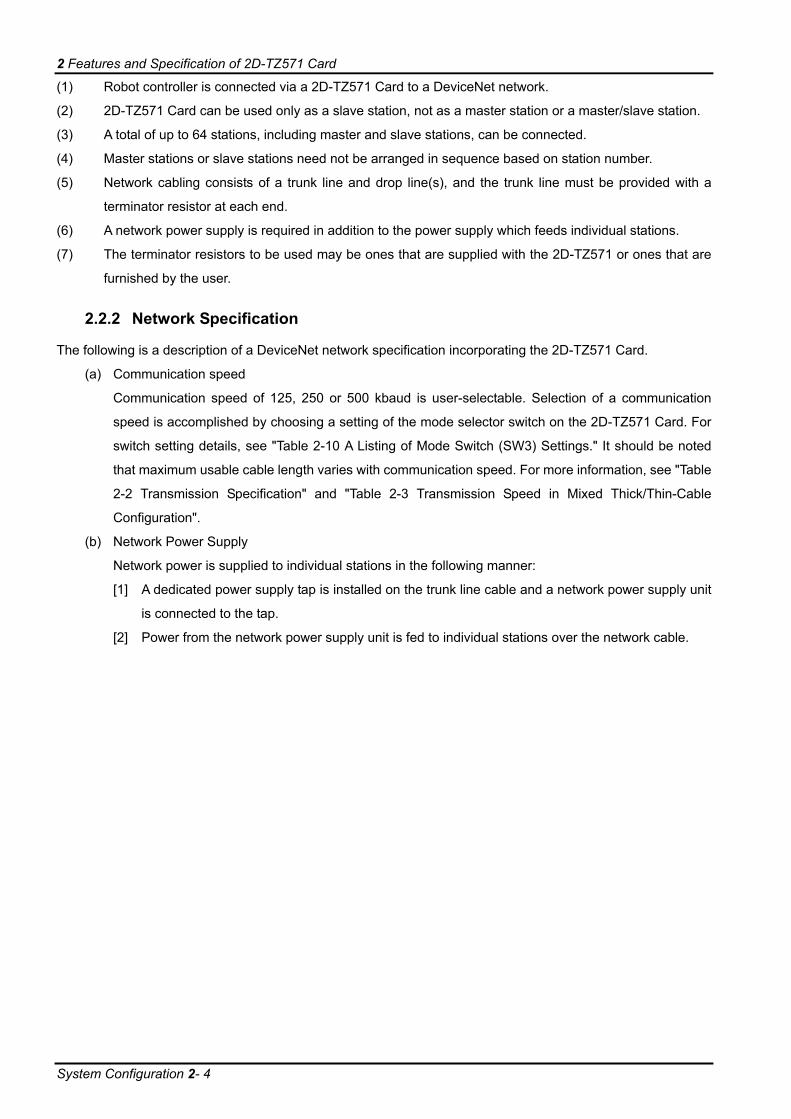
(1) Robot controller is connected via a 2D-TZ571 Card to a DeviceNet network.
(2) 2D-TZ571 Card can be used only as a slave station, not as a master station or a master/slave station.
(3) A total of up to 64 stations, including master and slave stations, can be connected.
(4) Master stations or slave stations need not be arranged in sequence based on station number.
(5) Network cabling consists of a trunk line and drop line(s), and the trunk line must be provided with a
terminator resistor at each end.
(6) A network power supply is required in addition to the power supply which feeds individual stations.
(7) The terminator resistors to be used may be ones that are supplied with the 2D-TZ571 or ones that are
furnished by the user.
2.2.2 Network Specification
The following is a description of a DeviceNet network specification incorporating the 2D-TZ571 Card.
(a) Communication speed
Communication speed of 125, 250 or 500 kbaud is user-selectable. Selection of a communication
speed is accomplished by choosing a setting of the mode selector switch on the 2D-TZ571 Card. For
switch setting details, see "Table 2-10 A Listing of Mode Switch (SW3) Settings." It should be noted
that maximum usable cable length varies with communication speed. For more information, see "Table
2-2 Transmission Specification" and "Table 2-3 Transmission Speed in Mixed Thick/Thin-Cable
Configuration".
(b) Network Power Supply
Network power is supplied to individual stations in the following manner:
[1] A dedicated power supply tap is installed on the trunk line cable and a network power supply unit
is connected to the tap.
[2] Power from the network power supply unit is fed to individual stations over the network cable.

2 Features and Specification of 2D-TZ571 Card
Specification 2- 5
2.3 Specification Table 2-1
Table 2-1 General Specification (2D-TZ571 Card Specification)
Item Specification Remark Type name of DeviceNet Slave Interface Card TZ571 -
Communication capability Both bit data and word data can be handled. -
Option slots which accept an interface card Slot 1/ Slot 2/Slot 3
Only one slot is usable at any time. (CR1D is provided with Slot 1 only.)
Number of cards accepted in slot One No more than one card is accepted.Concurrent use with other fieldbus (*1) Not permitted -
DeviceNet specification supported Release 2.0 - Type of station * Type of station: master or slave
Intended to serve as a slave station alone
Not intended to serve as a master station
Type of node DeviceNet slave (Group2 server) -
Transmission speed 125, 250, or 500 kbaud Rotary switch-selectable
Station number 0~63 Rotary switch-selectable (Default setting: 0)
Number of connections that can be generated (I/O connections)
One (polling) -
Transmission 1,024 maximum 128 bytes Number of I/O communication points per robot controller
Reception 1,024 maximum 128 bytes
Head number of input/output to/from robot controller 2000~
For more information about signal assignment, see "Table 2-7 A Listing of DeviceNet Signals."
Terminator resistor Uninstalled -
Input/output signal access
2D-TZ571 Card send/receive data is assigned to input/output signal No. 2000 and up. In a MELFA-BASIC V network, these signals are treated as input/output signals like parallel I/O signals are.
-
(*1)CC-Link Interface Card and Device Net Interface Card (both under development).
Table 2-2 Transmission Specification
Item Specification Medium Thick cable and thin cable Network configuration Bus type (trunk line/drop line) Data link method Polling
Trunk line Drop line Transmission
speed Thick cable Thin cable Mixed
Thick/Thin-Cable Maximum Total
125kbps 500m 156m 250kbps 250m 78m
Maximum length of cable (*1)
500kbps 100m100m see"Table2-3" 6m
39m
(*1)The maximum length of cable applies to DeviceNet specifications Release2.0 Volume1 and Volume2.

2 Features and Specification of 2D-TZ571 Card
Compatible Versions 2- 6
Table 2-3 Transmission Speed in Mixed Thick/Thin-Cable Configuration
Transmission Speed Maximum transmission speed in mixed thick/thin cable configuration 125kbps Length of thick cable + 5 x thin cable ≤ 500m 250kbps Length of thick cable + 2.5 x thin cable ≤ 250m 500kbps Length of thick cable + thin cable ≤ 100m
Table 2-4 A Listing of Robot Parameters Used in DeviceNet
Item Initial value Setting range Description
STOP2 -1, -1 -1 ~ 19999 A dedicated input parameter used to specify a dedicated input signal which causes robot program to be suspended. Please set 2000-3023 when setting it to the Input/Output signals of 2D-TZ571 Card. [Element 1] Stop input [Element 2] Pausing output (Because the parameter "STOP" is fixed at "0," DeviceNet uses "STOP 2" to define a suspend signal from outside.)
ORST2000
ORST2032 . .
ORST2992
00000000,
00000000,
00000000,
00000000
0/1/* Value of data sent over DeviceNet at signal output reset is specified. For more information, see "2.6 General-purpose Output Resetting Function."
DNSDLN 8 0 ~ 128 Number of transmission bytes in I/O communication over DeviceNet (0~128)
DNRDLN 8 0 ~ 128 Number of reception bytes in I/O communication over DeviceNet (0~128)
DNERR 0 0/1 A parameter specified for a temporary reset to clear error condition at the occurrence of error about DeviceNet. (1: reset enabled (but communication not to be performed) / 0: error at all times while anomaly exists in the link) * This parameter returns to initial value "0" when the operator resets power supply to the robot controller.
DNFIL 5000, 200 0 ~ 32767 The communication abnormality detection filter is specified. This error occurs if each error continues during specified time. [Element 1] Error 8410, 8440, 8441, 8442, 8460 [Element 2] Error 8430 [Unit]ms
2.4 Compatible Versions The table below shows the versions of the Controller and PC support software which are accommodated by the
2D-TZ571 Card.
Table 2-5 Compatible Versions
Name Version Robot Controller P7a or later PC support software RT ToolBox2: Not dependent on version

2 Features and Specification of 2D-TZ571 Card
Robot Controller Input/Output Signals 2- 7
2.5 Robot Controller Input/Output Signals
Input/output signals handled in the Robot Controller are in the range of 2000~3023 maximum irrespective of
station numbers.
Table 2-6 DeviceNet Input/Output Number
Input (received from master station) Output (sent to master station) Number 2000 ~ 3023 2000 ~ 3023
The data size of input/output signal is determined by specifying associated parameter (DNSDLN for
transmission or DNRDLN for reception) with a number of bytes.
The range of parameter settings is 0 to 128 bytes and an initial value is 8 bytes.
Table 2-7 A Listing of DeviceNet Signals
Number of bytes
Usable number of
points Start End Number of
bytes Usable number
of points Start End Number of bytes
Usable number of points Start End
0 0 - to - 43 344 2000 to 2343 86 688 2000 to 26871 8 2000 to 2007 44 352 2000 to 2351 87 696 2000 to 26952 16 2000 to 2015 45 360 2000 to 2359 88 704 2000 to 27033 24 2000 to 2023 46 368 2000 to 2367 89 712 2000 to 27114 32 2000 to 2031 47 376 2000 to 2375 90 720 2000 to 27195 40 2000 to 2039 48 384 2000 to 2383 91 728 2000 to 27276 48 2000 to 2047 49 392 2000 to 2391 92 736 2000 to 27357 56 2000 to 2055 50 400 2000 to 2399 93 744 2000 to 27438 64 2000 to 2063 51 408 2000 to 2407 94 752 2000 to 27519 72 2000 to 2071 52 416 2000 to 2415 95 760 2000 to 275910 80 2000 to 2079 53 424 2000 to 2423 96 768 2000 to 276711 88 2000 to 2087 54 432 2000 to 2431 97 776 2000 to 277512 96 2000 to 2095 55 440 2000 to 2439 98 784 2000 to 278313 104 2000 to 2103 56 448 2000 to 2447 99 792 2000 to 279114 112 2000 to 2111 57 456 2000 to 2455 100 800 2000 to 279915 120 2000 to 2119 58 464 2000 to 2463 101 808 2000 to 280716 128 2000 to 2127 59 472 2000 to 2471 102 816 2000 to 281517 136 2000 to 2135 60 480 2000 to 2479 103 824 2000 to 282318 144 2000 to 2143 61 488 2000 to 2487 104 832 2000 to 283119 152 2000 to 2151 62 496 2000 to 2495 105 840 2000 to 283920 160 2000 to 2159 63 504 2000 to 2503 106 848 2000 to 284721 168 2000 to 2167 64 512 2000 to 2511 107 856 2000 to 285522 176 2000 to 2175 65 520 2000 to 2519 108 864 2000 to 286323 184 2000 to 2183 66 528 2000 to 2527 109 872 2000 to 287124 192 2000 to 2191 67 536 2000 to 2535 110 880 2000 to 287925 200 2000 to 2199 68 544 2000 to 2543 111 888 2000 to 288726 208 2000 to 2207 69 552 2000 to 2551 112 896 2000 to 289527 216 2000 to 2215 70 560 2000 to 2559 113 904 2000 to 290328 224 2000 to 2223 71 568 2000 to 2567 114 912 2000 to 291129 232 2000 to 2231 72 576 2000 to 2575 115 920 2000 to 291930 240 2000 to 2239 73 584 2000 to 2583 116 928 2000 to 292731 248 2000 to 2247 74 592 2000 to 2591 117 936 2000 to 293532 256 2000 to 2255 75 600 2000 to 2599 118 944 2000 to 294333 264 2000 to 2263 76 608 2000 to 2607 119 952 2000 to 295134 272 2000 to 2271 77 616 2000 to 2615 120 960 2000 to 295935 280 2000 to 2279 78 624 2000 to 2623 121 968 2000 to 296736 288 2000 to 2287 79 632 2000 to 2631 122 976 2000 to 297537 296 2000 to 2295 80 640 2000 to 2639 123 984 2000 to 298338 304 2000 to 2303 81 648 2000 to 2647 124 992 2000 to 299139 312 2000 to 2311 82 656 2000 to 2655 125 1000 2000 to 299940 320 2000 to 2319 83 664 2000 to 2663 126 1008 2000 to 300741 328 2000 to 2327 84 672 2000 to 2671 127 1016 2000 to 301542 336 2000 to 2335 85 680 2000 to 2679 128 1024 2000 to 3023
2 Features and Specification of 2D-TZ571 Card
General-purpose Output Resetting Function 2- 8
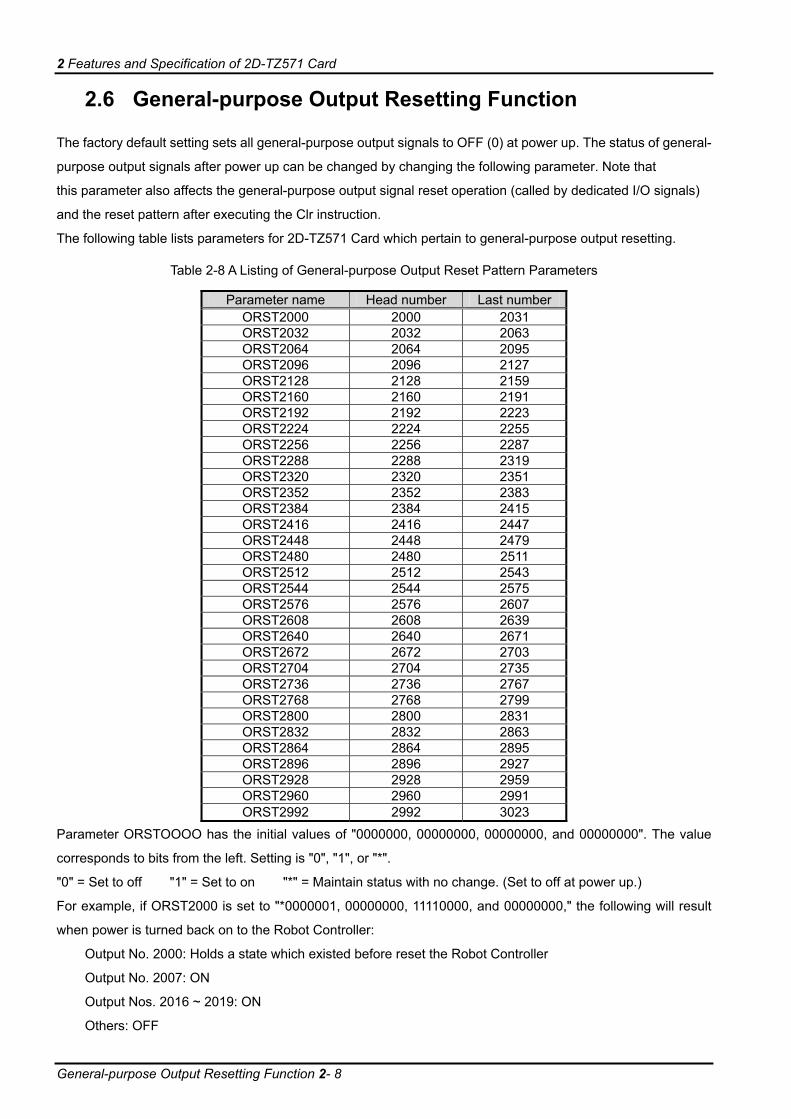
2.6 General-purpose Output Resetting Function
The factory default setting sets all general-purpose output signals to OFF (0) at power up. The status of general-
purpose output signals after power up can be changed by changing the following parameter. Note that
this parameter also affects the general-purpose output signal reset operation (called by dedicated I/O signals)
and the reset pattern after executing the Clr instruction.
The following table lists parameters for 2D-TZ571 Card which pertain to general-purpose output resetting.
Table 2-8 A Listing of General-purpose Output Reset Pattern Parameters
Parameter name Head number Last number ORST2000 2000 2031 ORST2032 2032 2063 ORST2064 2064 2095 ORST2096 2096 2127 ORST2128 2128 2159 ORST2160 2160 2191 ORST2192 2192 2223 ORST2224 2224 2255 ORST2256 2256 2287 ORST2288 2288 2319 ORST2320 2320 2351 ORST2352 2352 2383 ORST2384 2384 2415 ORST2416 2416 2447 ORST2448 2448 2479 ORST2480 2480 2511 ORST2512 2512 2543 ORST2544 2544 2575 ORST2576 2576 2607 ORST2608 2608 2639 ORST2640 2640 2671 ORST2672 2672 2703 ORST2704 2704 2735 ORST2736 2736 2767 ORST2768 2768 2799 ORST2800 2800 2831 ORST2832 2832 2863 ORST2864 2864 2895 ORST2896 2896 2927 ORST2928 2928 2959 ORST2960 2960 2991 ORST2992 2992 3023
Parameter ORSTOOOO has the initial values of "0000000, 00000000, 00000000, and 00000000". The value
corresponds to bits from the left. Setting is "0", "1", or "*".
"0" = Set to off "1" = Set to on "*" = Maintain status with no change. (Set to off at power up.)
For example, if ORST2000 is set to "*0000001, 00000000, 11110000, and 00000000," the following will result
when power is turned back on to the Robot Controller:
Output No. 2000: Holds a state which existed before reset the Robot Controller
Output No. 2007: ON
Output Nos. 2016 ~ 2019: ON
Others: OFF

2 Features and Specification of 2D-TZ571 Card
Hardware of 2D-TZ571 Card 2- 9
2.7 Hardware of 2D-TZ571 Card
The following subsections explain the steps followed to choose the rotary switch settings and LED indications on
the 2D-TZ571 Card.
2.7.1 Overall View
×10(SW1)
×1(SW2)
MODE (SW3)
LED
DeviceNet cable connector
Rotary switches (SW1/SW2/SW3)
Figure 2-2 Overall View of 2D-TZ571 Card
2.7.2 Rotary Switch
There are three rotary switches (SW1/SW2/SW3) provided on the 2D-TZ571 Card. The table below shows
settings which can be chosen from the rotary switches.
×1 (SW2)
×10 (SW1)
Table 2-9 A Listing of Station Number Selector Switch (SW1/SW2) Settings
Name Item Default setting Description Remark
x10 0 Specifies the tens digit of station number
Station number selector switch
x1 0 Specifies the units digit of station number
Setting range: 0~63 (If any setting outside the range of 0 to 63 is chosen, Error 8421 (DEVICENET Unit number switch is outside) will result with the "ERR." LED lighting up.) * Be careful to avoid selecting station numbers which overlap one another.
" Assign as small a number to the Master Station as possible " Station number can be chosen from a range of 0 to 63, but the characteristicof a DeviceNet network is such that a smaller station number carries ahigher transmission priority. Therefore, it is advisable that as small a numberas possible be assigned to Master Station.

2 Features and Specification of 2D-TZ571 Card
Hardware of 2D-TZ571 Card 2- 10
MODE (SW3)
Table 2-10 A Listing of Mode Switch (SW3) Settings
Name Setting Function Description Remark 0 1 2
Prohibited from use
Use of these settings will result in Error 8420 (DEVICENET Mode switch is outside).
3 Card acts as a slave station. Communication speed: 125 Kbaud
4 Card acts as a slave station. Communication speed: 250 Kbaud
5
Slave function
Card acts as a slave station. Communication speed: 500 Kbaud
6 7 8
Prohibited from use
Use of these settings will result in Error 8420 (DEVICENET Mode switch is outside).
9 Prohibited from use
Use of these settings will result in Error 8420 (DEVICENET Mode switch is outside).
A Transmission/reception test is carried out. Communication speed: 125 Kbaud
B Transmission/reception test is carried out. Communication speed: 250 Kbaud
C
Communication test
Transmission/reception test is carried out. Communication speed: 500 Kbaud
Mode switch
D-F Prohibited from use
Use of these settings will result in Error 8420 (DEVICENET Mode switch is outside).

2 Features and Specification of 2D-TZ571 Card
Hardware of 2D-TZ571 Card 2- 11
2.7.3 LEDs
There are five LEDs provided on the 2D-TZ571 Card, each of which lets you know the operating state of the
Interface Card by going on, flickering, or going off.
RUNERR
MS
(GREEN)
(GREEN)
(GREEN) (RED)
(RED)
NS
Figure 2-3 Placement of LEDs
Table 2-11 A Listing of LEDs (in Mode 3~5)
LED name Color Indications On: Operating normally RUN Green Off: Watchdog timer error On: Station number setting error ERR Red Flickering: Change has been made to Station Number Selector Switch and/or Mode Selector Switch settings during the operation of the unit. On: Communication enabled MS Green Flickering: Parameter error On: Communication going on Green Flickering: Waiting for communication (robot being in initialization process or waiting for other equipment to get ready to start communication) On: There are overlapping station numbers. Bus off error (anomaly in communication line)
Red
Flickering: Communication with Mater Station is suspended.
NS
Green/red Off: Network power supply is not lost.
RUNERR
MS
NS
(GREEN)
(GREEN)
(GREEN)(RED)
(RED)
Figure 2-4 On-Off State of LEDs under Normal Operation

2 Features and Specification of 2D-TZ571 Card
Hardware of 2D-TZ571 Card 2- 12
Table 2-12 A Listing of LEDs (in Mode A~C: Communication Test)
RUN MS ERR State On Flickering Off Communication test going on On On Off Normal completion On Off On Abnormal completion
MS
RUNERR
NS
(GREEN)
(GREEN)
(GREEN)
(RED)
(RED)
Figure 2-5 On-Off State of LEDs at Normal Completion

3 Out of the Package
Checking Component Parts 3- 13
3. Out of the Package
3.1 Checking Component Parts
The product you purchased comes standard with the components listed in the table below. Check the product to
ensure that it is complete with these components.
Table 3-1 Standard Components of Product
No. Item name Type name Quantity [1] Instruction manual (this document) BFP-A8735 1
[2] DeviceNet Slave Interface Card (2D-TZ571 Card)
TZ571 1
[3] Ferrite core E04SR301334 1 [4] Online connector for communication MSTB2.5/5-STF-5.08AU M 1
Note: Numbers in the table corresponds to those in the figure below.
[1] [2] [3] [4]
Figure 3-1 A Listing of Components Supplied with the Product
3.2 Compatible Versions
Please confirm the Compatible version of the Robot controller and the PC support software. (Refer to 2.4
Compatible Versions)
3.3 Items To Be Furnished by User
The following table shows the items that the user is required to have ready before using the 2D-TZ571 Card.
Table 3-2 Items To Be Furnished by User
Item Requirements Master station DeviceNet-compliant master station Communication cable (*1) Cable specifically designed for use with DeviceNet
Melco disclaims all guarantees of DeviceNet system performance if any cable other than those described herein is used. There are limits to maximum total cable length and inter-station cable length.
(*1) For more information, visit "ODVA" website at http://www.odva.org/.

4 Connection and Wiring
Installing 2D-TZ571 Card 4- 14
4. Connection and Wiring
4.1 Installing 2D-TZ571 Card
For instructions on how to install an optional card onto the Robot Controller, see the section under the heading
"Installing Optional Devices" which is included in the controller's instruction manual "Controller Setup - From
Basic Operating Procedure to Maintenance."
Only one 2D-TZ571 Card is permitted to be installed into either of the option slots (1 ~ 3) of the Robot Controller.
If more than one card is installed into the slots, Error 8450 (DEVICENET Install more than one) will occur.
4.1.1 For CR1D Controller
Remove the option slot interface cover on the rear of the Controller and install a 2D-TZ571 Card into the slot.
During installation, use the handle fitted to the Interface Card.
Connector
Interface card
Handle
Disconnecting lever
Slot1
Figure 4-1 Installing 2D-TZ571 Card (in the case of CR1D Controller)

4 Connection and Wiring
Installing 2D-TZ571 Card 4- 15
4.1.2 For CR2D Controller
Remove any one of the interface covers provided for the option slots 1 to 3 on the rear of the Controller and
install a 2D-TZ571 Card into the slot. During installation, use the handle fitted to the Card.
Interface cover
Interface cover-removing lever
Connector
Interface card
Handle
Disconnecting lever
SLOT1
SLOT2
SLOT3
Figure 4-2 Installing 2D-TZ571 Card (in the case of CR2D Controller)

4 Connection and Wiring
Installing 2D-TZ571 Card 4- 16
4.1.3 For CR3D Controller
Open the door of the Robot Controller and you will see R700 CPU unit located at the right-hand end. Remove
any one of the interface covers provided for the option slots 1 to 3 on the CPU unit and install a 2D-TZ571 Card
into the slot.
During installation, use the handle fitted to the Card.
Interface card
Handle
Disconnecting lever
Connector
Interface cover
Interface cover-removing
lever
R700 CPU unit R700 CPU unit
Figure 4-3 Installing 2D-TZ571 Card (in the case of CR3D Controller)

4 Connection and Wiring
Connecting Communication Cable to 2D-TZ571 Card 4- 17
4.2 Connecting Communication Cable to 2D-TZ571 Card
4.2.1 Connecting Communication Cable
The DeviceNet connector on the 2D-TZ571 Card is arranged as shown below. It is affixed with adhesive labels,
each having a color corresponding to the color of the communication cable. Connect the communication cable,
noting the color-coding of the connector labels and the cables.
V- (black)
CAN_L (blue)
Shield (drain wire)
CAN_H (white)
V+ (red)
Figure 4-4 DeviceNet Connector Pin Assignment
4.2.2 Grounding Network
The DeviceNet network uses a single-point ground. Establish a ground near the mid-part of the network.
Connect the shield (drain wire) of the cable to the ground of the power supply unit, using Class D (Class 3)
grounding.
If more than one power supply unit exists on the network, ground only the power supplier unit closer to the
mid-part of the network, doing away with grounding elsewhere.
Also, if more than one power supply unit is employed on the network, use a power supply tap.
Power supply tap
Power supply unit
FG V+ V- FG V+ V- FG V+ V-
Power supply tap (near the mid-part of network)
CAN_H V+
Shield (drain wire)CAN_L V-
Power supply tap
Power supply unit
Power supply unit
Figure 4-5 Grounding DeviceNet Network

4 Connection and Wiring
Precautions about Network Power Supply 4- 18
4.3 Precautions about Network Power Supply
4.3.1 Arranging Network Power Supply Unit(s)
Follow the procedure given below to decide on the arrangement of network power supply unit(s):
[1] Figure up a sum of current consumptions by individual stations which are connected to the
network.
[2] Take measurement of the network's total length.
[3] Referring to Table 4-1 Maximum Current Capacity Sufficient for Master/Slave Stations
Relative to Length of Thick-cable Network and Table 4-2 Maximum Current Capacity Sufficient
for Master/Slave Stations
Relative to Length of Thin-cable Network, determine a maximum current capacity which
corresponds to the distance covered by the network and the type of cable used.
[4] If the sum obtained in Step [1] is no greater than that obtained in Step [3], any of the power
supply unit arrangements described in the next subsection may be used.
[5] If the sum obtained in Step [1] is greater than that obtained in Step [3], check to see, by
reference to the description in the next subsection, whether a power supply unit being located
near the mid-part of the network is sufficient to supply power to all the stations.
If the check made in Step [5] shows that a single power supply unit is not sufficient to feed all the stations,
increase the number of power supply units.
Table 4-1 Maximum Current Capacity Sufficient for Master/Slave Stations
Relative to Length of Thick-cable Network
Length of network (m) 0 25 50 100 150 200 250 300 350 400 450 500
Maximum current (A) 8.00 8.00 5.42 2.93 2.01 1.53 1.23 1.03 0.89 0.78 0.69 0.63
Table 4-2 Maximum Current Capacity Sufficient for Master/Slave Stations
Relative to Length of Thin-cable Network
Length of network (m)
0 10 20 30 40 50 60 70 80 90 100
Maximum current (A)
3.00 3.00 3.00 2.06 1.57 1.26 1.06 0.91 0.80 0.71 0.64
About current capacity of network power supply unit Network power supply unit should be such that current capacity available is greater than total current consumption required. If current capacity is found insufficient, more than one power supply unit may be used. However, when using plural power supply units, install a power supply tap.
Caution
4 Connection and Wiring
Precautions about Network Power Supply 4- 19
4.3.2 Arrangement of Network Power Supply Unit and Calculation of Current Capacity
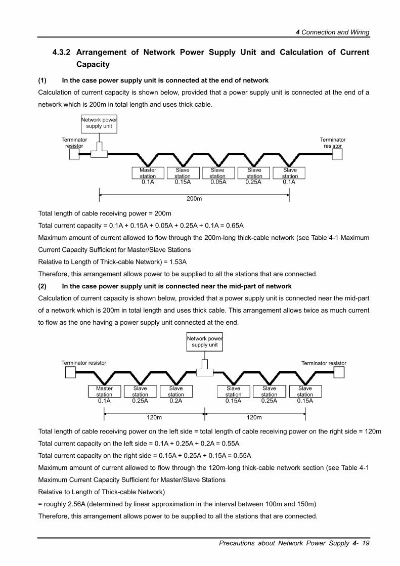
(1) In the case power supply unit is connected at the end of network
Calculation of current capacity is shown below, provided that a power supply unit is connected at the end of a
network which is 200m in total length and uses thick cable.
Network power supply unit
Terminator resistor
Master station
Slave station
0.1A 0.15A 0.05A 0.25A 0.1A
200m
Slave station
Slave station
Slave station
Terminator resistor
Total length of cable receiving power = 200m
Total current capacity = 0.1A + 0.15A + 0.05A + 0.25A + 0.1A = 0.65A
Maximum amount of current allowed to flow through the 200m-long thick-cable network (see Table 4-1 Maximum
Current Capacity Sufficient for Master/Slave Stations
Relative to Length of Thick-cable Network) = 1.53A
Therefore, this arrangement allows power to be supplied to all the stations that are connected.
(2) In the case power supply unit is connected near the mid-part of network
Calculation of current capacity is shown below, provided that a power supply unit is connected near the mid-part
of a network which is 200m in total length and uses thick cable. This arrangement allows twice as much current
to flow as the one having a power supply unit connected at the end.
Network power supply unit
Terminator resistor
Master station
Slave station
0.1A 0.25A 0.2A 0.15A 0.25A 0.15A
120m 120m
Terminator resistor
Slave station
Slave station
Slave station
Slave station
Total length of cable receiving power on the left side = total length of cable receiving power on the right side = 120m
Total current capacity on the left side = 0.1A + 0.25A + 0.2A = 0.55A
Total current capacity on the right side = 0.15A + 0.25A + 0.15A = 0.55A
Maximum amount of current allowed to flow through the 120m-long thick-cable network section (see Table 4-1
Maximum Current Capacity Sufficient for Master/Slave Stations
Relative to Length of Thick-cable Network)
= roughly 2.56A (determined by linear approximation in the interval between 100m and 150m)
Therefore, this arrangement allows power to be supplied to all the stations that are connected.
4 Connection and Wiring
Precautions about Network Power Supply 4- 20
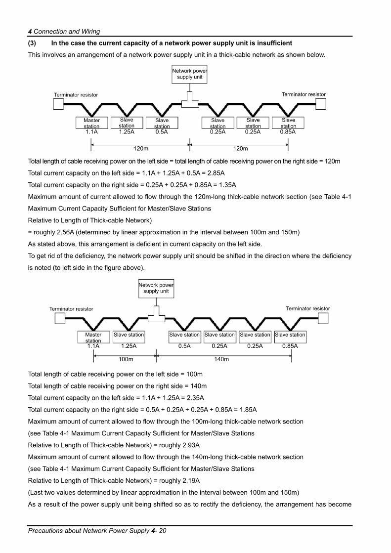
(3) In the case the current capacity of a network power supply unit is insufficient
This involves an arrangement of a network power supply unit in a thick-cable network as shown below.
Network power supply unit
Terminator resistor
Master station
Slave station
1.1A 1.25A 0.5A 0.25A 0.25A 0.85A
120m 120m
Terminator resistor
Slave station
Slave station
Slave station
Slave station
Total length of cable receiving power on the left side = total length of cable receiving power on the right side = 120m
Total current capacity on the left side = 1.1A + 1.25A + 0.5A = 2.85A
Total current capacity on the right side = 0.25A + 0.25A + 0.85A = 1.35A
Maximum amount of current allowed to flow through the 120m-long thick-cable network section (see Table 4-1
Maximum Current Capacity Sufficient for Master/Slave Stations
Relative to Length of Thick-cable Network)
= roughly 2.56A (determined by linear approximation in the interval between 100m and 150m)
As stated above, this arrangement is deficient in current capacity on the left side.
To get rid of the deficiency, the network power supply unit should be shifted in the direction where the deficiency
is noted (to left side in the figure above).
Network power
supply unit
Terminator resistor
Master station
Slave station
1.1A 1.25A 0.5A 0.25A 0.25A 0.85A
100m 140m
Terminator resistor
Slave station Slave station Slave station Slave station
Total length of cable receiving power on the left side = 100m
Total length of cable receiving power on the right side = 140m
Total current capacity on the left side = 1.1A + 1.25A = 2.35A
Total current capacity on the right side = 0.5A + 0.25A + 0.25A + 0.85A = 1.85A
Maximum amount of current allowed to flow through the 100m-long thick-cable network section
(see Table 4-1 Maximum Current Capacity Sufficient for Master/Slave Stations
Relative to Length of Thick-cable Network) = roughly 2.93A
Maximum amount of current allowed to flow through the 140m-long thick-cable network section
(see Table 4-1 Maximum Current Capacity Sufficient for Master/Slave Stations
Relative to Length of Thick-cable Network) = roughly 2.19A
(Last two values determined by linear approximation in the interval between 100m and 150m)
As a result of the power supply unit being shifted so as to rectify the deficiency, the arrangement has become

4 Connection and Wiring
Precautions about Network Power Supply 4- 21
capable of allowing power to be supplied to all the stations that are connected.
(4) In the case both a trunk line and a drop line are included in a network
Calculation of current capacity is shown below, provided that a power supply unit is connected to a network
comprised of a 200m-long thick-cable trunk line and a 6m-long thin-cable drop line.
Network power
supply unit
Terminator resistor
Master station
Slave station Slave station Slave station
Slave station
1.0A 0.15A 0.05A 0.25A
0.1A
200m
Terminator resistor
Total length of thick cable receiving power = 200m
Total length of thin cable receiving power = 6m
Total current capacity = 0.5A + 0.15A * 0.05A * 0.25A + 0.1A = 1.05A
Maximum amount of current allowed to flow through the 200m-long thick-cable section
(see Table 4-1 Maximum Current Capacity Sufficient for Master/Slave Stations
Relative to Length of Thick-cable Network) = 1.53A
Maximum amount of current allowed to flow through a 6m-long drop line
(see Table 4-3 Maximum Current Capacity Corresponding to Length of Drop-line Cable) = 0.75A
Total amount of current to equipment connected to the drop line = 0.1A
Therefore, this arrangement allows power to be supplied to all the stations that are connected.
Table 4-3 Maximum Current Capacity Corresponding to Length of Drop-line Cable
Length of drop line (m) 0.30 0.90 1.50 2.25 3.00 4.50 6.00Maximum amount of current (A) 3.00 3.00 3.00 2.00 1.50 1.00 0.75
4 Connection and Wiring
Checking Connections 4- 22
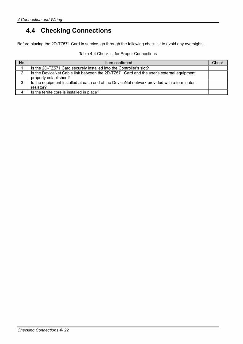
4.4 Checking Connections
Before placing the 2D-TZ571 Card in service, go through the following checklist to avoid any oversights.
Table 4-4 Checklist for Proper Connections
No. Item confirmed Check1 Is the 2D-TZ571 Card securely installed into the Controller's slot? 2 Is the DeviceNet Cable link between the 2D-TZ571 Card and the user's external equipment
properly established?
3 Is the equipment installed at each end of the DeviceNet network provided with a terminator resistor?
4 Is the ferrite core is installed in place?

5 Communication Testing
Communication Test Procedure 5- 23
5. Communication Testing
This section describes the procedure followed to perform transmission/reception tests on the 2D-TZ571 Card
being connected one-to-one to other DeviceNet devices over a communication cable.
There are no limits to the number settings for the stations at the other end of the line, but they may not overlap
those for the 2D-TZ571 Card. The description below assumes that settings for the master station are completed.
For instructions on settings for the master station, refer to the manual that accompanies.
5.1 Communication Test Procedure
[1] Set the station number switch on the 2D-TZ571 Card to an appropriate number.
[2] Set the mode switch on the 2D-TZ571 Card to any of A, B, and C. (Communication speed of the
Card need to be matched to that of the DeviceNet device at other end of the line.)
[3] Install the 2D-TZ571 Card into the option slot on the Robot Controller.
[4] Connect the 2D-TZ571 Card to the DeviceNet device at other end of the line using the
DeviceNet Cable.
[5] Turn on power to the network.
[6] Turn on power to the DeviceNet station at other end of the line.
[7] Turn on power to the Robot Controller.
[8] The 2D-TZ571 Card will automatically begin a communication test, and the MS LED will keep
on flashing green during the test.
[9] If the MS LED is lit green while the ERR LED is off, this indicates a normal completion of the test.
* Normal completion will result in the occurrence of Error 8490
(DeviceNet communication test mode).
If the MS LED is off while the ERR LED is lit, this indicates an abnormal completion of the test.
* Abnormal completion will result in the occurrence of Errors 8491-8494
About the operation of the Robot Controller while in communication test modeWhile in communication test mode, the Robot Controller operates as it would if the DeviceNet InterfaceCard is not installed.
CAUTION

6 Startup Procedure
Initial Startup 6- 24
6. Startup Procedure
This section describes the procedure which is necessary when constructing a DeviceNet system. Note: The
description below assumes that the master station and other network components are in a state of readiness to
operate and that the initial setup of the robot is completed.
6.1 Initial Startup
The following procedure is used to accomplish initial startup:
[1] Set the station number switch on the 2D-TZ571 Card to an appropriate number.
[2] Set the mode switch on the 2D-TZ571 Card to any of 3, 4, and 5. (Communication speed of the
Card need be matched to that of the devices on the network.)
[3] Install the 2D-TZ571 Card into the option slot on the Robot Controller.
[4] Connect the DeviceNet cable to the 2D-TZ571 Card.
[5] Turn on power to the network.
[6] Turn on power to the other devices on the network.
[7] Turn on power to the Robot.
[8] If any error associated with the DeviceNet network is generated on the robot side, set parameter
E8430 or DNERR to enable a temporary recovery from such error. (Resetting step will permit
you to clear such error.)
[9] Specify the number of reception bytes (DNRDLN) and the number of transmission bytes
(DNSDLN). (For information about the relevant parameters, see "Table 2-4 A Listing of Robot
Parameters Used in DeviceNet".)
[10] Turn off power to the robot, and then back on.
6.2 Normal Operation
For normal operation, the following startup procedure is used:
[1] Turn ON power to the network.
[2] Turn ON power to the other devices on the network.
[3] Turn ON power to the Robot.
This will let the robot to establish connection with the DeviceNet network and start I/O communications with the
master station.

7 Troubleshooting
A Listing of Errors 7- 25
7. Troubleshooting
Check this section before concluding that your system is out of order.
7.1 A Listing of Errors
An error number contains information as listed below OOOO
• An error marked with an asterisk requires a power reset. Take a corrective action which is stated in the "Solutions" section of the table below.
• The type of error is indicated by a 4-digit number. • Errors are sorted into three classifications:
H: High-level error ..... Servo mechanism is shut down. L: Low-level error ...... Operation is suspended. C: Caution ................. Operation is allowed to continue.
Table 7-1 A Listing of DeviceNet-related Errors
Error No. Causes and Solutions
Error message DEVICENET Card failure Cause Abnormality of the DEVICENET card is detected H.8410* Solution Please exchange the DEVICENET card
Error message DEVICENET Mode switch is outside Cause The mode switch is outside H.8420* Solution Please correct the mode switch
Error message DEVICENET Unit number switch is outside Cause The unit number switch is outside H.8421* Solution Please correct the unit number switch
Error message DEVICENET Communication error Cause Network fail or Master setting is illegal H.8430 Solution Please confirm the network (speed, cable, terminator) or the master
unit Error message DEVICENET Unit number overlaps Cause There are more than one unit with the same unit number on the
network H.8440
Solution Please confirm the other unit number Error message DEVICENET Network power failure Cause Network power is turned off H.8441 Solution Please turn on network power Error message DEVICENET Other units not found Cause Other units are not connected on the network H.8442 Solution Please confirm the other units
Error message DEVICENET Install more than one Cause Only one 2D-TZ571 card can be installed H.8450 Solution Please install only one 2D-TZ571 card
Error message DEVICENET Set other fieldbus Cause Only one. fieldbus card can be installed H.8451 Solution Only one fieldbus card is installed
Error message DEVICENET Timeout Cause The I/O communication was can not be done in time. L.8460 Solution Please confirm the other units or power supply of network.

7 Troubleshooting
At the Occurrence of Error 8460 7- 26
Error message DEVICENET Param load write error (*1) Cause Parameter can not be load and written H.8470* Solution Turn the power OFF and ON once
Error message DEVICENET Send byte is outside Cause Send byte number setting of is out of range H.8471* Solution Please correct the send byte number setting
Error message DEVICENET Receive byte outside Cause Receive byte number setting is outside H.8472* Solution Please correct the receive byte number setting
Error message DEVICENET Send-receive are 0 Cause Both receive and send byte number setting are 0 H.8473* Solution Please change receive or send byte number setting
Error message DEVICENET Communication test mode Cause It is communication test mode. C.8490 Solution Please change the mode switch to 3-5 after the test ends. Error message DEVICENET Comm-test unit number (*2) Cause Unit numbers overlap is detected by communication test H.8491* Solution Please confirm the other units number Error message DEVICENET Comm-test busoff (*2) Cause Busoff is detected by communication test H.8492* Solution Please confirm communication speed, cable, terminator Error message DEVICENET Comm-test net power (*2) Cause Network power off is detected by communication test H.8493* Solution Please turn on network power Error message DEVICENET Comm-test send-receive (*2) Cause Data can not send and receive normal by communication test H.8494* Solution Please confirm connection situation of others, communication speed,
cable and terminator (*1)Pram : Parameter
(*2)Comm : Communication
7.2 At the Occurrence of Error 8460
(DEVICENET Timeout) When this error occurred, take the corrective action suggested in the troubleshooting chart in Section 7.1. If the
error still persists, check to see the following:
(1) Is power to the Master Station unit on?
(2) Is the Master Station functioning properly?
* 8460 occurs unless the Master Station is up and running before power is turned on to the Robot Controller.
* If Master Station provides function to set it’s parameter automatically and the function is used, it is late for
running and 8460 may occur.
(3) Is the Master Station properly connected?
(4) Are the parameter settings on the Master Station consistent with those on the Robot Controller?
(5) Doesn't any of the peripheral equipment contain a noise emission source?
(6) If it is desired to ignore Error 8460, change DNERR parameter setting.

8 Appendix
Displaying Information about Optional Cards 8- 27
8. Appendix
8.1 Displaying Information about Optional Cards
RT ToolBox2 (Options) lets you to have information about the option cards displayed on the screen.
Expand the workspace tree and click "Slotn:DEVICENT" entry under "Option Cards." Information about the
2D-TZ571 Card will appear on the property window.
Properties are displayed.
Attributes are displayed.
Figure 8-1 Information about Optional Cards from RT ToolBox2
Table 8-1 Information about the 2D-TZ571 Card
Display item Example Meaning Remark Card name DEVICENET Card designation
[Node Num] 63 Station number switch Station number: 0~63 [Mode] 3 Mode switch Mode switch (0~F) [Baud Rate] 125k Communication speed 125k
250k 500k
[Input] 8(2000 - 2063) Number of reception bytes (signal number)
0 (-) ~ 128 (2000 – 3023)
[Output] 8(2000 - 2063) Number of transmission bytes (signal number)
0 (-) ~ 128 (2000 – 3023)
[Status] 00C0 I/O communication state 0000: offline 0040: stop 0080: communication-ready 00C0: I/O communication going on
[Info] 0000 Error information Slave function error code [SNo] 12345678 Serial number Serial number
Car
d in
form
atio
n
[H/W Ver] 0 Card group number


HEADQUARTERS
EUROPEMITSUBISHI ELECTRIC EUROPE B.V.German BranchGothaer Straße 8D-40880 RatingenPhone: +49 (0)2102 / 486-0Fax: +49 (0)2102 / 486-1120
CZECH REPUBLICMITSUBISHI ELECTRIC EUROPE B.V.Czech BranchAvenir Business Park, Radlická 714/113aCZ-158 00 Praha 5Phone: +420 - 251 551 470Fax: +420 (0)251-551-471
FRANCEMITSUBISHI ELECTRIC EUROPE B.V.French Branch25, Boulevard des BouvetsF-92741 Nanterre CedexPhone: +33 (0)1 / 55 68 55 68Fax: +33 (0)1 / 55 68 57 57
IRELANDMITSUBISHI ELECTRIC EUROPE B.V.Irish BranchWestgate Business Park, BallymountIRL-Dublin 24Phone: +353 (0)1 4198800Fax: +353 (0)1 4198890
ITALYMITSUBISHI ELECTRIC EUROPE B.V.Italian BranchViale Colleoni 7I-20041 Agrate Brianza (MB)Phone: +39 039 / 60 53 1Fax: +39 039 / 60 53 312
POLANDMITSUBISHI ELECTRIC EUROPE B.V.Poland BranchKrakowska 50PL-32-083 BalicePhone: +48 (0)12 / 630 47 00Fax: +48 (0)12 / 630 47 01
SPAINMITSUBISHI ELECTRIC EUROPE B.V.Spanish BranchCarretera de Rubí 76-80E-08190 Sant Cugat del Vallés (Barcelona)Phone: 902 131121 // +34 935653131Fax: +34 935891579
UKMITSUBISHI ELECTRIC EUROPE B.V.UK BranchTravellers LaneUK-Hatfield, Herts. AL10 8XBPhone: +44 (0)1707 / 27 61 00Fax: +44 (0)1707 / 27 86 95
JAPANMITSUBISHI ELECTRIC CORPORATIONOffice Tower “Z” 14 F8-12,1 chome, Harumi Chuo-KuTokyo 104-6212Phone: +81 3 622 160 60Fax: +81 3 622 160 75
USAMITSUBISHI ELECTRIC AUTOMATION, Inc.500 Corporate Woods ParkwayVernon Hills, IL 60061Phone: +1 847 478 21 00Fax: +1 847 478 22 53
EUROPEAN REPRESENTATIVES
AUSTRIAGEVAWiener Straße 89AT-2500 BadenPhone: +43 (0)2252 / 85 55 20Fax: +43 (0)2252 / 488 60
BELGIUMKoning & Hartman b.v.Woluwelaan 31BE-1800 VilvoordePhone: +32 (0)2 / 257 02 40Fax: +32 (0)2 / 257 02 49
BOSNIA AND HERZEGOVINAINEA BH d.o.o.Aleja Lipa 56BA-71000 SarajevoPhone: +387 (0)33 / 921 164Fax: +387 (0)33 / 524 539
BULGARIAAKHNATON4 Andrej Ljapchev Blvd. Pb 21BG-1756 SofiaPhone: +359 (0)2 / 817 6004Fax: +359 (0)2 / 97 44 06 1
CZECH REPUBLICAutoCont C.S. s.r.o.Technologická 374/6CZ-708 00 Ostrava-PustkovecPhone: +420 595 691 150Fax: +420 595 691 199
CZECH REPUBLICB:ELECTRIC, s.r.o.Mladoboleslavská 812CZ-197 00 Praha 19 - KbelyPhone: +420 286 850 848, +420 724 317 975Fax: +420 286 850 850
DENMARKBeijer Electronics A/SLykkegårdsvej 17, 1.DK-4000 RoskildePhone: +45 (0)46/ 75 76 66Fax: +45 (0)46 / 75 56 26
FINLANDBeijer Electronics OYJaakonkatu 2FIN-01620 VantaaPhone: +358 (0)207 / 463 500Fax: +358 (0)207 / 463 501
GREECEUTECO A.B.E.E.5, Mavrogenous Str.GR-18542 PiraeusPhone: +30 211 / 1206 900Fax: +30 211 / 1206 999
HUNGARYAXICONT AUTOMATIKA KFT.(ROBOT CENTER) Reitter F. U. 132HU-1131 BudapestPhone: +36 1 / 412-0882Fax: +36 1 / 412-0883
MALTAALFATRADE Ltd.99, Paola HillMalta- Paola PLA 1702Phone: +356 (0)21 / 697 816Fax: +356 (0)21 / 697 817
NETHERLANDSHIFLEX AUTOM.TECHNIEK B.V.Wolweverstraat 22NL-2984 CD RidderkerkPhone: +31 (0)180 – 46 60 04Fax: +31 (0)180 – 44 23 55
EUROPEAN REPRESENTATIVES
NETHERLANDSKoning & Hartman b.v.Haarlerbergweg 21-23NL-1101 CH AmsterdamPhone: +31 (0)20 / 587 76 00Fax: +31 (0)20 / 587 76 05
NORWAYBeijer Electronics ASPostboks 487NO-3002 DrammenPhone: +47 (0)32 / 24 30 00Fax: +47 (0)32 / 84 85 77
ROMANIASIRIUS TRADING & SERVICES SRLAleea Lacul Morii Nr. 3RO-060841 Bucuresti, Sector 6Phone: +40 (0)21 / 430 40 06Fax: +40 (0)21 / 430 40 02
SERBIAINEA SR d.o.o.Izletnicka 10SER-113000 SmederevoPhone: +381 (0)26 / 617 163Fax: +381 (0)26 / 617 163
SLOVAKIACS MTrade Slovensko, s.r.oVajanskeho 58SK-92101 PiestanyPhone: +421 (0)33 / 7742 760Fax: +421 (0)33 / 7735 144
SLOVENIAINEA d.o.o.Stegne 11SI-1000 LjubljanaPhone: +386 (0)1 / 513 8100Fax: +386 (0)1 / 513 8170
SWEDENBeijer Electronics Automation ABBox 426SE-20124 MalmöPhone: +46 (0)40 / 35 86 00Fax: +46 (0)40 / 35 86 02
SWITZERLANDOmni Ray AGIm Schörli 5CH-8600 DübendorfPhone: +41 (0)44 / 802 28 80Fax: +41 (0)44 802 / 28 28
TURKEYGTSBayraktar Bulvari Nutuk Sok. No:5TR-34775 Yukari Dudullu-Umraniye-ISTANBULPhone: +90 (0)216 526 39 90Fax: +90 (0)216 526 3995
UKRAINECSC Automation Ltd.4-B, M. Raskovoyi St.UA-02660 KievPhone: +380 (0)44 / 494 33 55Fax: +380 (0)44 / 494-33-66
MIDDLE EAST REPRESENTATIVE
ISRAELILAN & GAVISH Ltd.24 Shenkar St., Kiryat ArieIL-49001 Petah-TiqvaPhone: +972 (0)3 / 922 18 24Fax: +972 (0)3 / 924 0761
AFRICAN REPRESENTATIVE
SOUTH AFRICACBI Ltd.Private Bag 2016ZA-1600 IsandoPhone: + 27 (0)11 / 977 0770Fax: + 27 (0)11 / 977 0761
MITSUBISHIELECTRIC
FACTORY AUTOMATIONMitsubishi Electric Europe B.V. /// FA - European Business Group /// Gothaer Straße 8 /// D-40880 Ratingen /// GermanyTel.: +49(0)2102-4860 /// Fax: +49(0)2102-4861120 /// [email protected] /// www.mitsubishi-automation.com
MITSUBISHI ELECTRIC