scs900 setup “do’s & don’ts presented by:. finding a suitable location to set up the gps...
TRANSCRIPT

SCS900
Setup “Do’s & Don’ts
Presented By:

Finding a suitable location to set up the GPS base station
Fixed Height Tripod Setup(Mobile )
T – Bar Setup (Permanent)
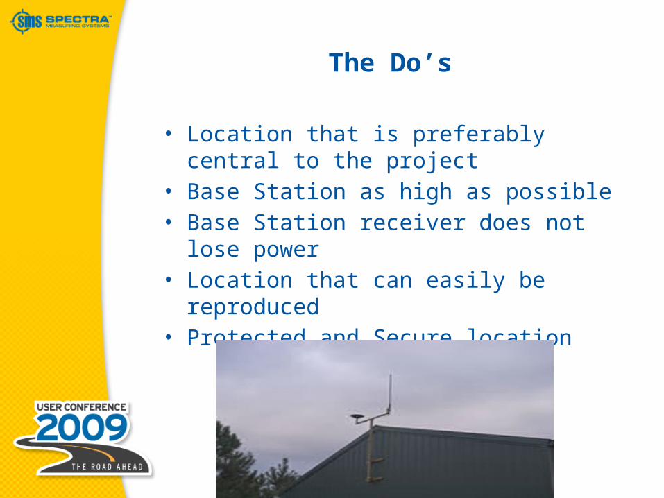
The Do’s
• Location that is preferably central to the project
• Base Station as high as possible• Base Station receiver does not lose
power• Location that can easily be reproduced• Protected and Secure location

The Don’ts
• Radio transmission equipment• Trees• Tall Buildings• Ponds• Overhead power lines• Electrical generation facilities
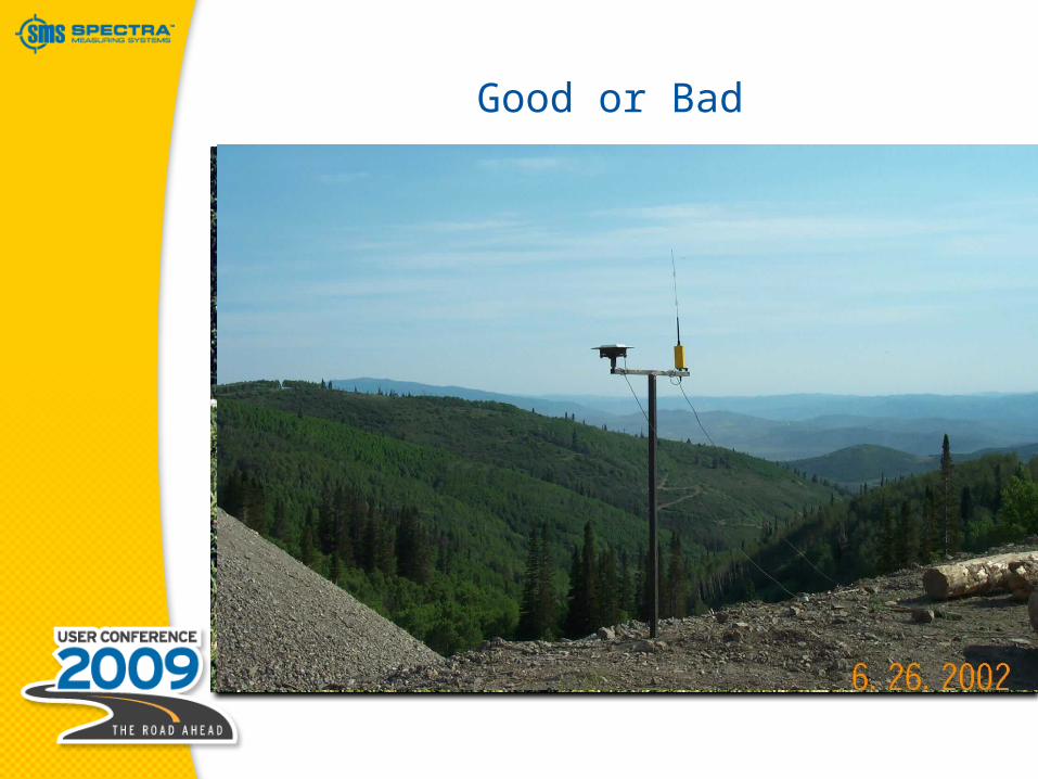
Good or Bad

SCS900
Starting SCS900
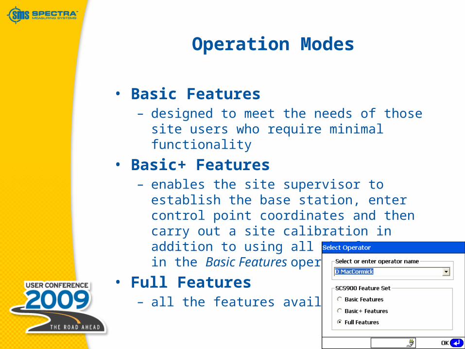
Operation Modes
• Basic Features– designed to meet the needs of those site
users who require minimal functionality
• Basic+ Features– enables the site supervisor to establish the
base station, enter control point coordinates and then carry out a site calibration in addition to using all the features in the Basic Features operation mode
• Full Features– all the features available

SCS900
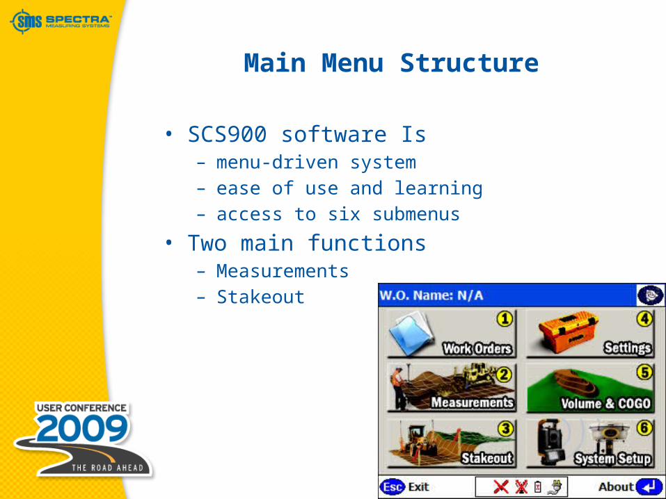
Main Menu Structure
Main Menu Structure
• SCS900 software Is– menu-driven system– ease of use and learning– access to six submenus
• Two main functions– Measurements– Stakeout

Work Orders menu
• Work Orders menu– New– Open– Change Design– Complete Work Order– Export/Import Data
Measurement menu
• Measurement menu– Check Surface Grade– Check Grade of Roadway– Check Material Thickness– Measure Surface– Measure Site Features– Display Real-Time Cut/Fill– Advanced Measurements
Stakeout menu
• Stakeout menu– Point– Line– Side Slope & Catch Point– Plane– Surface / Road– Enter/Edit Stakeout Points

Settings menu
• Settings menu– Units & Formats– GPS Settings– Internet & VRS Settings– Instrument Setup & Adjustment– Stakeout Settings– Data Output Options– COM Port Data Output Option– Radio Baud Rate
Volume & COGO menu
• Volume & COGO menu– Review & Edit Surface– Review Design Features– Compute Distance & Area– Create Stakeout Points– Create/Edit Road Data
System Setup menu
• System Setup menu (GPS)– Set up Base– Set up Rover– Calibrate Site– Recheck System Setup– Enter/Measure Control Points– Switch to Total Station Setup

System Setup menu
• System Setup menu (TS)– Connect Instrument– Set up Total Station– Instrument Functions Menu– Recheck System Setup– Enter/Measure Control Points– Switch to GPS System Setup

SCS900
Creating a Site
SCS900
SCS900
Starting the GPS base station

Positioning the GPS base station
• Located at a known or unknown point– Pick a point from the control point list– Set up on an unknown position– Enter its local coordinate– Enter its lat/long/height– Set up radio only
Starting the GPS base station
• AutoBase®– remembers how the previous setup was
made– reconnects the components– selects the appropriate radio channel– network number– starts to transmit GPS positions

Starting the GPS base station
• Before you start the base station, ensure that you do the following:– Connect the controller to the receiver, if
using a cable. Alternatively, you can make the connection using Bluetooth wireless technology from within the SCS900 software.
– Turn on the controller.– Start the SCS900 software.– Create a new work order on a new site if
not previously created.– Enter the control point coordinates for the
project .

Setup Base
• To set up the base station– System Setup– Setup Base– Select Connection
• Wireless• Cable

Connection Method
• Wireless– connect through Bluetooth wireless
technology
• Cable– connect through a cable
Wireless Connection
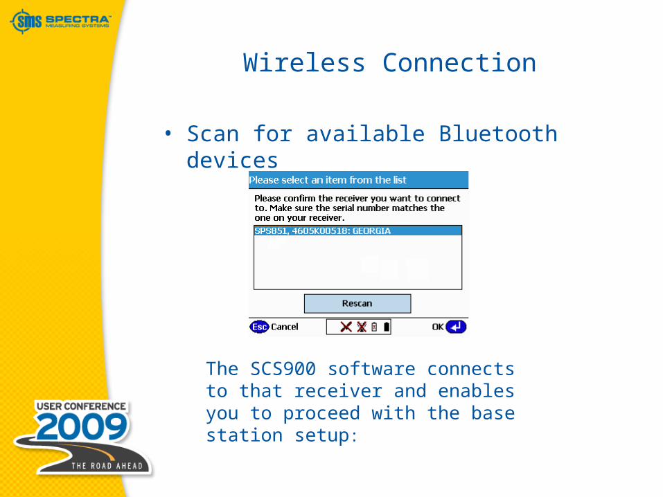
• Scan for available Bluetooth devices
The SCS900 software connects to that receiver and enables you to proceed with the base station setup:

Correction Method
• Transmitting RTK Corrections– Via radio in the receiver– Via Trimble/PacCrest radio using cable– Via Trimble Bluetooth radio– Via a third-party radio– Via a cell phone

Position the Base
• Located at a known or unknown point• Non-available Options are grayed out

Setup on unknown location
• Option only if site has not yet been calibrated
• Once a site has been calibrated:– Located at a known point– Control point in the calibration process– Established using the measure control point
function

Setup on unknown location
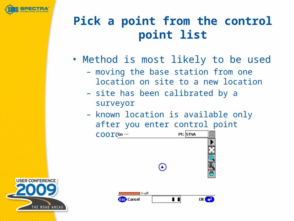
Pick a point from the control point list
• Method is most likely to be used– moving the base station from one location
on site to a new location– site has been calibrated by a surveyor– known location is available only after you
enter control point coordinates

Enter its local coordinate
• Known point– enter the base station location
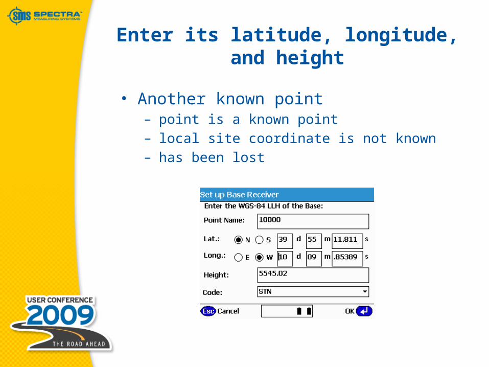
Enter its latitude, longitude, and height
• Another known point– point is a known point– local site coordinate is not known– has been lost
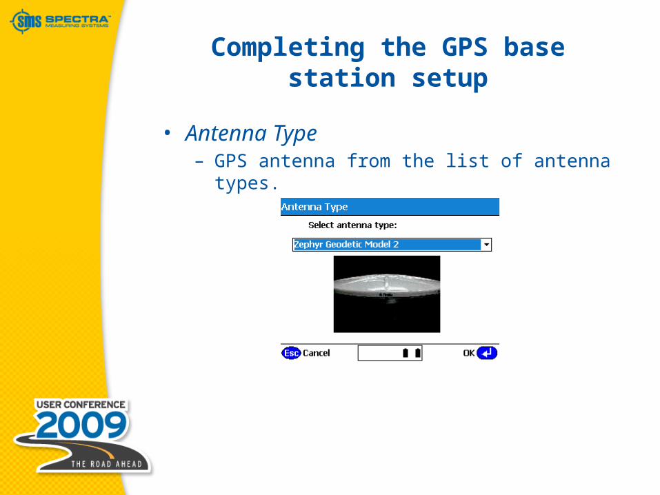
Completing the GPS base station setup
• Antenna Type– GPS antenna from the list of antenna types.
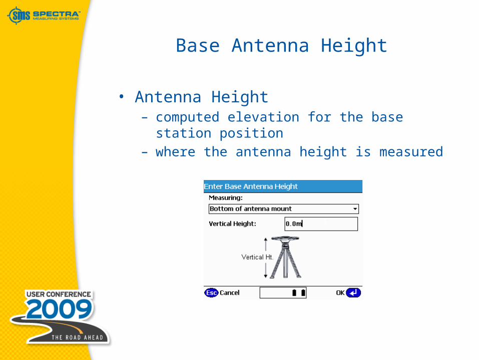
Base Antenna Height
• Antenna Height– computed elevation for the base station
position– where the antenna height is measured
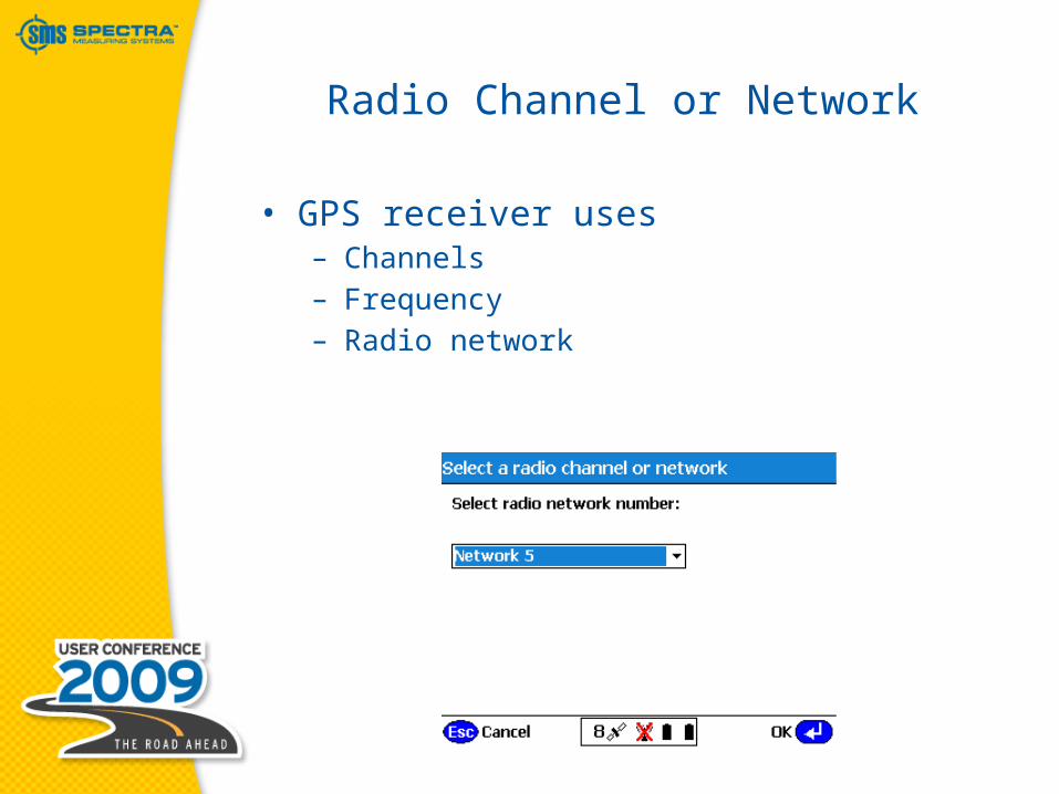
Radio Channel or Network
• GPS receiver uses– Channels– Frequency– Radio network
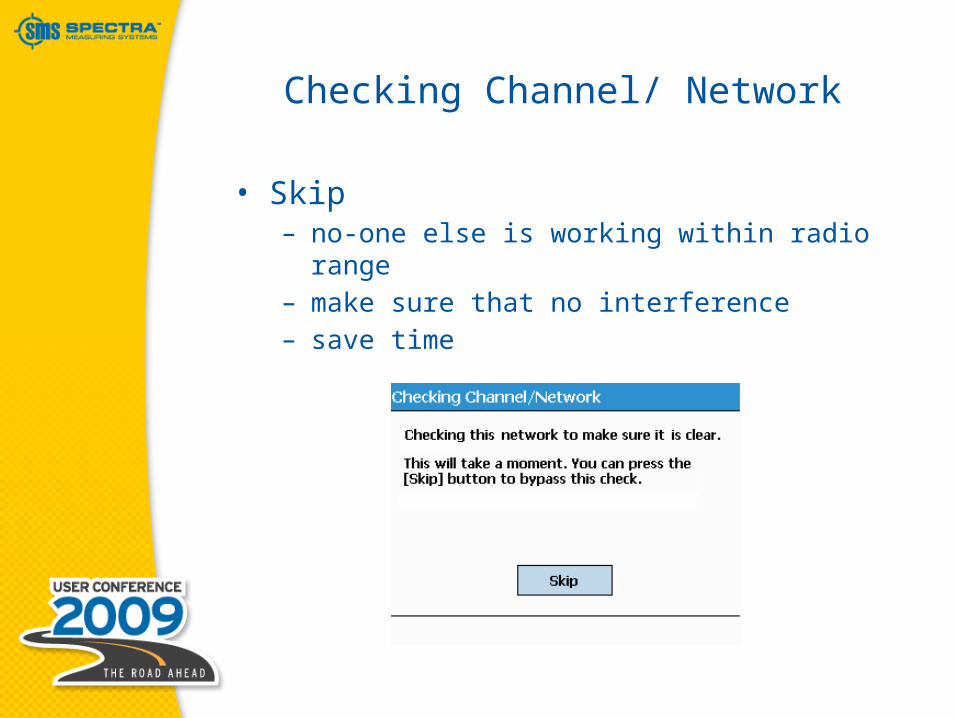
Checking Channel/ Network
• Skip– no-one else is working within radio range– make sure that no interference– save time

Set Up Base Complete
• Base Station information– logged to the work order report file– hard copy record– re-established
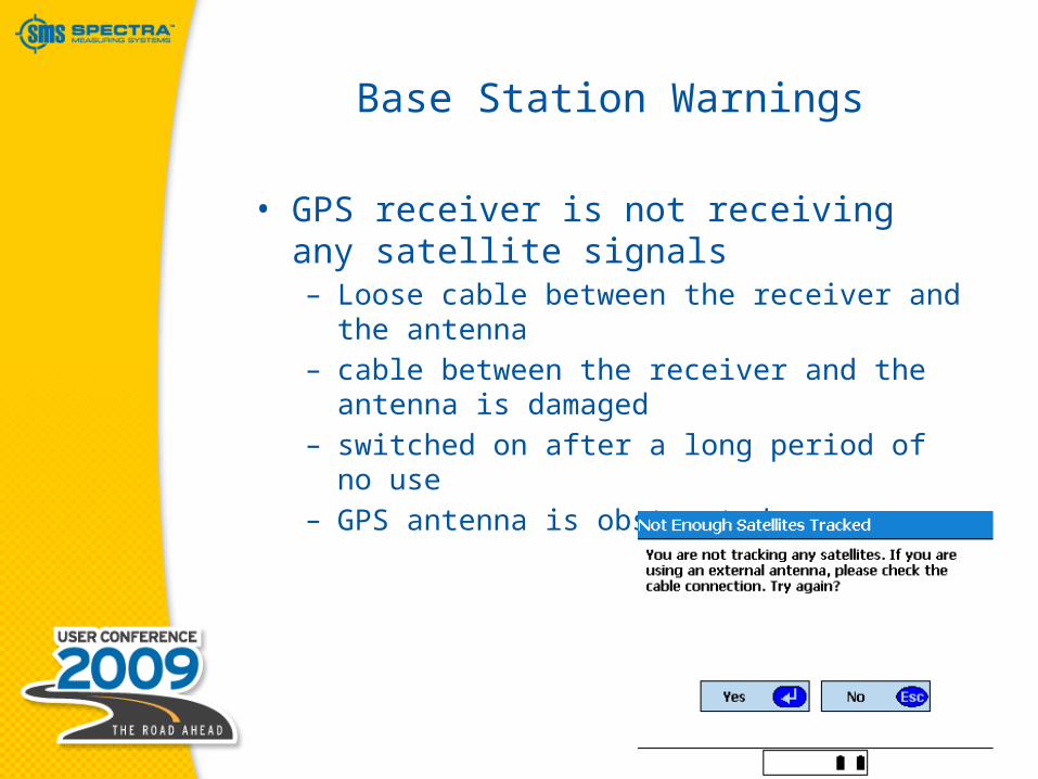
Base Station Warnings
• GPS receiver is not receiving any satellite signals– Loose cable between the receiver and the
antenna– cable between the receiver and the
antenna is damaged– switched on after a long period of no use– GPS antenna is obstructed
SCS900
Site Calibrations
Types of site calibrations
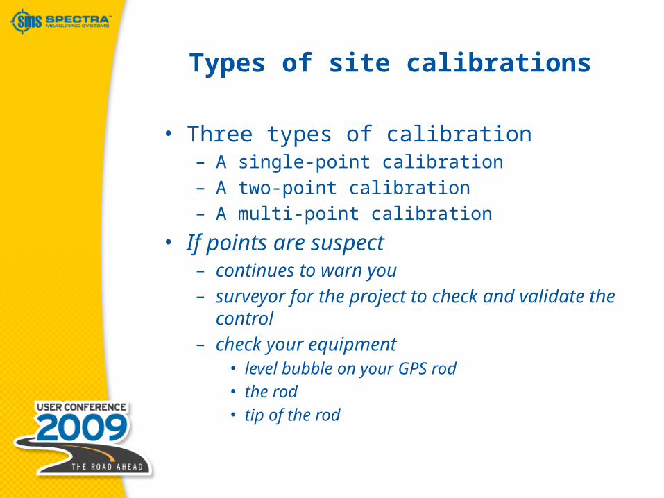
• Three types of calibration– A single-point calibration– A two-point calibration– A multi-point calibration
• If points are suspect– continues to warn you– surveyor for the project to check and
validate the control– check your equipment
• level bubble on your GPS rod• the rod• tip of the rod

Site Calibrations
• Includes datum transformation, map projection, horizontal & vertical adjustment
• Can select from library or DC file
This is the GPS calibration!
WGS84
Lat, Long,Height
Local
North, East,Elevation
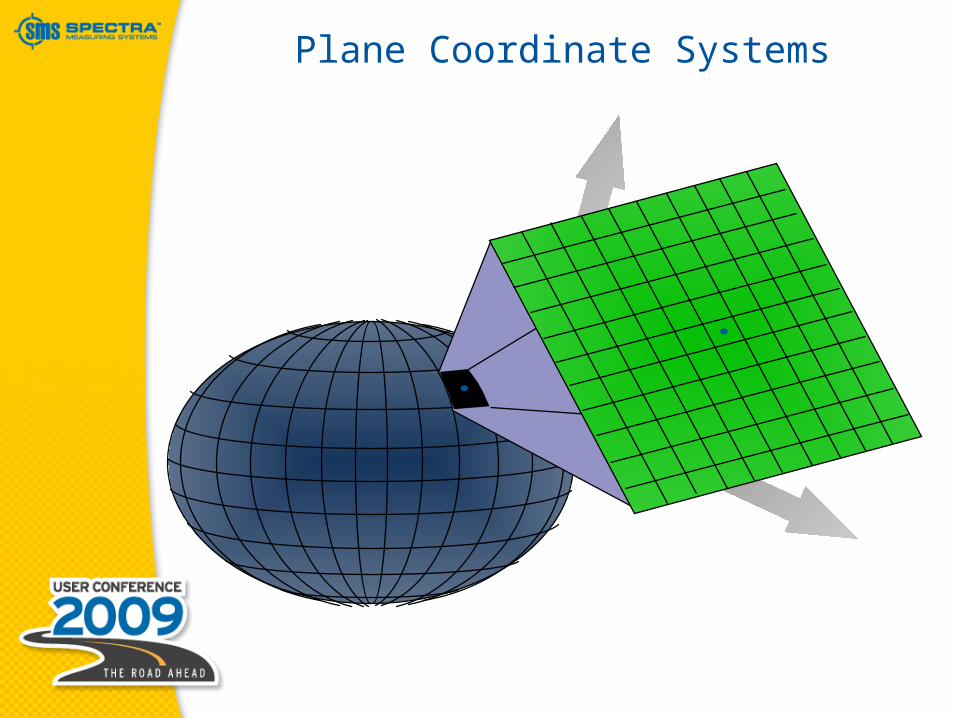
Plane Coordinate Systems

Horizontal Adjustment
•Horizontal Adjustment– Rotation– Translation– Scale

Horizontal Adjustment
= GPS observation= Control Point

Rotation

Translation

Scale

Horizontal Residuals
Resid
ual

Residuals
• Useful indicator– Quality of the calibration– Control– Measurement
• Expected magnitude of a residual– quality of the control points– field procedure– measurement methods– size of the site