scs conveyor system - · pdf filescs-fo scs-2w-fo ... non-motorized unloading): to one ......
TRANSCRIPT
SCS CONVEYOR SYSTEM
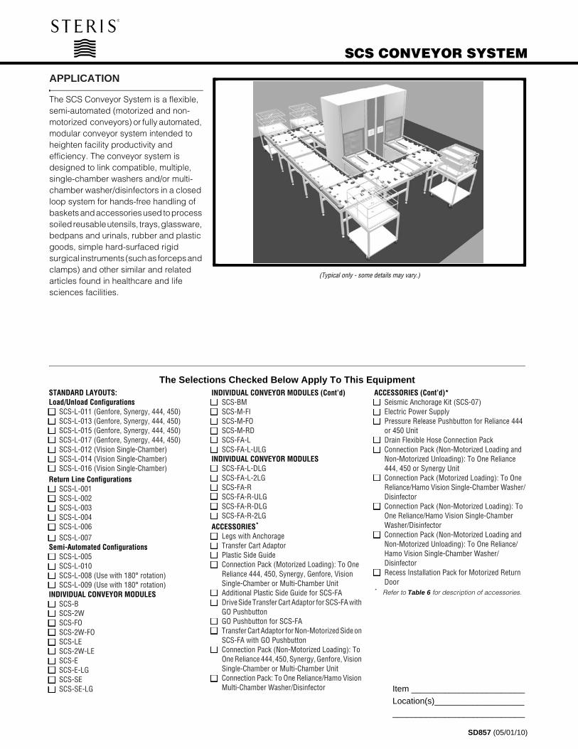
(Typical only - some details may vary.)
APPLICATION
The SCS Conveyor System is a flexible, semi-automated (motorized and non-motorized conveyors) or fully automated, modular conveyor system intended to heighten facility productivity and efficiency. The conveyor system is designed to link compatible, multiple, single-chamber washers and/or multi-chamber washer/disinfectors in a closed loop system for hands-free handling of baskets and accessories used to process soiled reusable utensils, trays, glassware, bedpans and urinals, rubber and plastic goods, simple hard-surfaced rigid surgical instruments (such as forceps and clamps) and other similar and related articles found in healthcare and life sciences facilities.
The SelectSTANDARD LAYOUTS:Load/Unload Configurations❑ SCS-L-011 (Genfore, Synergy, 444, 450) ❑ SCS-L-013 (Genfore, Synergy, 444, 450)❑ SCS-L-015 (Genfore, Synergy, 444, 450)❑ SCS-L-017 (Genfore, Synergy, 444, 450)❑ SCS-L-012 (Vision Single-Chamber)❑ SCS-L-014 (Vision Single-Chamber)❑ SCS-L-016 (Vision Single-Chamber)Return Line Configurations❑ SCS-L-001❑ SCS-L-002❑ SCS-L-003❑ SCS-L-004❑ SCS-L-006❑ SCS-L-007Semi-Automated Configurations❑ SCS-L-005❑ SCS-L-010❑ SCS-L-008 (Use with 180° rotation)❑ SCS-L-009 (Use with 180° rotation)INDIVIDUAL CONVEYOR MODULES❑ SCS-B❑ SCS-2W❑ SCS-FO❑ SCS-2W-FO❑ SCS-LE❑ SCS-2W-LE❑ SCS-E❑ SCS-E-LG❑ SCS-SE❑ SCS-SE-LG
SD857 (05/01/10)
Item ________________________Location(s)___________________
____________________________
ions Checked Below Apply To This EquipmentINDIVIDUAL CONVEYOR MODULES (Cont’d)❑ SCS-BM❑ SCS-M-FI❑ SCS-M-FO❑ SCS-M-RD❑ SCS-FA-L❑ SCS-FA-L-ULGINDIVIDUAL CONVEYOR MODULES❑ SCS-FA-L-DLG❑ SCS-FA-L-2LG❑ SCS-FA-R❑ SCS-FA-R-ULG❑ SCS-FA-R-DLG❑ SCS-FA-R-2LGACCESSORIES*
❑ Legs with Anchorage❑ Transfer Cart Adaptor❑ Plastic Side Guide❑ Connection Pack (Motorized Loading): To One
Reliance 444, 450, Synergy, Genfore, Vision Single-Chamber or Multi-Chamber Unit
❑ Additional Plastic Side Guide for SCS-FA❑ Drive Side Transfer Cart Adaptor for SCS-FA with
GO Pushbutton❑ GO Pushbutton for SCS-FA❑ Transfer Cart Adaptor for Non-Motorized Side on
SCS-FA with GO Pushbutton❑ Connection Pack (Non-Motorized Loading): To
One Reliance 444, 450, Synergy, Genfore, Vision Single-Chamber or Multi-Chamber Unit
❑ Connection Pack: To One Reliance/Hamo Vision Multi-Chamber Washer/Disinfector
ACCESSORIES (Cont’d)*❑ Seismic Anchorage Kit (SCS-07)❑ Electric Power Supply❑ Pressure Release Pushbutton for Reliance 444
or 450 Unit❑ Drain Flexible Hose Connection Pack❑ Connection Pack (Non-Motorized Loading and
Non-Motorized Unloading): To One Reliance 444, 450 or Synergy Unit
❑ Connection Pack (Motorized Loading): To One Reliance/Hamo Vision Single-Chamber Washer/Disinfector
❑ Connection Pack (Non-Motorized Loading): To One Reliance/Hamo Vision Single-Chamber Washer/Disinfector
❑ Connection Pack (Non-Motorized Loading and Non-Motorized Unloading): To One Reliance/Hamo Vision Single-Chamber Washer/Disinfector
❑ Recess Installation Pack for Motorized Return Door
* Refer to Table 6 for description of accessories.

DESCRIPTION
The SCS Conveyor System is designed to quietly (minimal operational sound level) load/unload 24 x 24" [610 x 610 mm] Amscomatic and Reliance® Series racks, and to interface with the following washers:
• Reliance® and Hamo® Genfore™ Washer/Disinfector
• Reliance® 444 Single-Chamber Washer/Disinfector (from S/N 3624500xxx)
• Reliance® 450 Glassware Washer (from S/N 3624502xxx)
NOTE: For Reliance 444 and Reliance 450 washers up to S/N 3624402xxx, call STERIS to verify if SCS Conveyor System can be made compatible.
• Reliance® and Hamo® Synergy® Washer Disinfector
• Reliance® and Hamo® Vision® Single-Chamber Washer/Disinfector
• Reliance® and Hamo® Vision® Multi-Chamber Washer/Disinfector (not compatible to Load/Unload conveyors)
The SCS Conveyor System also interfaces with the following transfer carts:
• FD24-300 (Reliance 444, 450, Synergy, Genfore and Vision Single-Chamber and Multi-Chamber
• FD21-800 (Reliance 444, 450, Synergy, Genfore and Vision Single-Chamber and Multi-Chamber)
• FD61-700 (Universal Transfer Cart).
STANDARDS
This SCS Conveyor System meets the applicable requirements of the following standards, as certified by UL:
• Underwriters Laboratories (UL) Standard UL 61010-1 Second Edition
• Canadian Standards Association (CSA) CAN/CSA C22.2 No. 61010-1 Second Edition
Governing Directive for the affixing of the CE mark:
• Machinery Directive 2006/42/EC
Standards applied to demonstrate conformity to the directives:
• International Standard IEC 61010-1 Second Edition
• International Standard IEC 61326-1:2005
Conformity to other applicable directives:
• Electromagnetic Compatibility 2004/108/EC
• Low Voltage 2006/95/EC
SIZE (W x H x L)
All dimensions listed are for individual modules.
Overall dimensions:
• 31-3/4 x 31 x 31-3/4" (806 x 787 x 806 mm)
Other dimensions (SCS-FA):
• FA-1LG
» 41-3/8 x 31 x 31-3/4"(1041 x 787 x 806 mm)
• FA-2LG
» 51 x 31 x 31-3/4"(1295 x 787 x 806 mm)
Normal height:
• 31" (787 mm) from the floor
Height adjustment (range):
• 29 to 33" (737 to 838 mm)
FEATURES
NOTE: Expert STERIS Systems Planners must assist in designing a configuration to an existing or new system, focusing on the most efficient use of equipment and space.
Each conveyor type (see Table 1) is equipped with either free or motorized rollers. For motorized rollers, the drive mechanism is provided by a 65 W gear motor.
The conveyor frame is constructed of #304 stainless steel (No. 4 finish). The Plastic Side Guides (SCS-03) are made of 3/16" (5 mm) thick blue ABS plastic.
The pneumatic cylinders are used to push/pull racks in and out of the process chamber, or to index racks automatically from a SCS-FA. The pneumatic guides are used to stabilize racks on all sides during automated change of directions.
The proximity sensors automatically detect basket position and are designed to operate in a soiled/wet environment.
Drip pans, located under the conveyor surface, allow for rack drainage collection following the loading/unloading process. A drain opening (sized for 1-1/2" NPT female adaptor) is provided in the drip pan for connection to the facility drain line or fitted with a bottle to collect drainage.
An additional Plastic Side Guide (SCS-03 or SCS-26) is supplied to close a conveyor side if a Transfer Cart Adapter (SCS-02 or SCS-29, accessory) is not required.
A lift gate conveyor (SCS-E-LG or SCS-SE-LG) can be supplied and easily opened by the user to allow access to the other side of the conveyor layout loop (typically used with cabinet washers installed side-by-side). SCS-FA-ULG, SCS-FA-DLG and SCS-FA-2LG have built-in motorized lift gates.
A motorized return door (SCS-M-RD) can be supplied and easily opened by the user to allow access to the other side of the conveyor layout loop (typically used with cabinet washers installed side-by-side).
NOTE: The door is equipped with an obstruction sensor to detect any door obstruction. If an obstruction is present, door automatically opens.
SCS Conveyor Solutions (see Table 1) is a flexible, modular system that allows workflow designs to be created for efficient transport and ergonomic handling of racks. The solutions range from simple load/unload designs to fully automated conveyor designs.
2

SAFETY FEATURES
The SCS Conveyor System is equipped with one electrical power supply (mounted under conveyor frame) for each four powered conveyors. To de-energize conveyor layout, either turn power supplies to OFF and wait for green indicator lights to turn OFF or (for conveyor types interfaced with a Reliance Synergy unit) press EMERGENCY STOP pushbutton.
For SCS-FO or SCS-2W-FO conveyor types interfaced with a Reliance 444 washer/disinfector, a Reliance 450 washer or a Reliance/Hamo Vision Single-Chamber washer/disinfector, a pressure-release pushbutton is supplied as an accessory.
NOTE: Conveyors are never turned OFF unless the conveyor power supply ON/OFF switch or facility circuit breaker is in OFF position.
ACCESSORIES
The SCS Conveyor System is designed with a complete package of accessories (see Table 2) to enable great design flexibility.
CONTROL SYSTEM
Each conveyor equipped with a feed-in (FI) or feed-out (FO) system to load or unload a washer/disinfector or any fully automated conveyor (SCS-FA) is equipped (see Table 5) with a PLC controller. Other automatic conveyor designs use relays and proximity sensors to detect baskets and/or racks and control operation.
INSTALLATION
The SCS Conveyor System is designed to be freestanding. The minimum clearance between the finished floor and the conveyor is 29" (737 mm). The minimum service clearance for the motorized conveyors (motorized side) is 10" (254 mm) if access is available on both sides of the conveyor; 17" (432 mm) if access is only on one side of the conveyor.
PREVENTIVE MAINTENANCE
Customers are encouraged to contact STERIS concerning annual maintenance programs. Under the terms of these programs, preventive maintenance, adjustments and replacement of worn parts are provided on a scheduled basis to help ensure optimal equipment performance and help minimize untimely or costly schedule interruptions. STERIS maintains a worldwide staff of well-equipped, factory-trained technicians to provide these services, as well as on-site installation, training and expert repair services. Contact STERIS for details.
3

Table 1. SCS Conveyor Solutions (Simple Load/Unload Design to Fully Automated Conveyor Design)
Load/Unload SCS Conveyor Load/Unload SCS Conveyor Features:
• Load point at individual washer
• Users select washer to feed
• Manual rack transportation using TC
• Stand alone return line
• Low queue capacity
Semi-Automated SCS Semi-Automated SCS Features:
• Multiple load points
• Users select washer to feed
• Manual rack transportation using conveyor
• Connected return line
• Moderate queue capacity
Fully-Automated SCS Fully-Automated SCS Features:
• Set it and forget it – Single load point
• Traffic manager selects washer
• Automated rack transportation
• Connected return line
• Maximum queue capacity/foot print ratio
Washer/Disinfector
Washer/Disinfector
Washer/Disinfector
Washer/Disinfector
Vision Single-Chamber Washer/Disinfectors
4

Table 2. Standard SCS Return Lines and Semi-Automated Configurations
Configuration Description
SCS-L-001 Three module motorized return line. Return line provides the transportation of racks to the soiled side from the clean side.
Configuration fits with a single-chamber washer/disinfector, single load and single unload modules.
Please refer to Drawing 920-513-846.
SCS-L-002 Three module motorized return line with an automated return line door. Return line provides the transportation of racks to the soiled side from the clean side with an automated return door to minimize cross-contamination. Configuration fits with a single-chamber washer/disinfector, single load and single unload modules.
Please refer to Drawing 920-513-846.
LEGEND
Legs with AnchorageTransfer Card Adaptor Electrical Power Supply Wall Unload Flow
Work Flow
Pneumatic CylinderSCS Conveyor Module
Non-Motorized Roller Motorized Roller
05 1111
05 1114
5
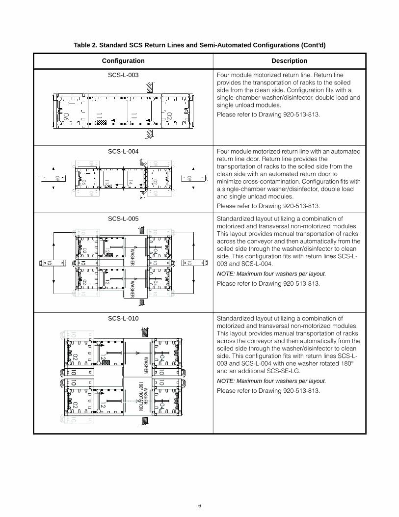
SCS-L-003 Four module motorized return line. Return line provides the transportation of racks to the soiled side from the clean side. Configuration fits with a single-chamber washer/disinfector, double load and single unload modules.
Please refer to Drawing 920-513-813.
SCS-L-004 Four module motorized return line with an automated return line door. Return line provides the transportation of racks to the soiled side from the clean side with an automated return door to minimize cross-contamination. Configuration fits with a single-chamber washer/disinfector, double load and single unload modules.
Please refer to Drawing 920-513-813.
SCS-L-005 Standardized layout utilizing a combination of motorized and transversal non-motorized modules. This layout provides manual transportation of racks across the conveyor and then automatically from the soiled side through the washer/disinfector to clean side. This configuration fits with return lines SCS-L-003 and SCS-L-004.
NOTE: Maximum four washers per layout.
Please refer to Drawing 920-513-813.
SCS-L-010 Standardized layout utilizing a combination of motorized and transversal non-motorized modules. This layout provides manual transportation of racks across the conveyor and then automatically from the soiled side through the washer/disinfector to clean side. This configuration fits with return lines SCS-L-003 and SCS-L-004 with one washer rotated 180° and an additional SCS-SE-LG.
NOTE: Maximum four washers per layout.
Please refer to Drawing 920-513-813.
Table 2. Standard SCS Return Lines and Semi-Automated Configurations (Cont’d)
Configuration Description
0211 1106
021106 14
0909
09
0909
09
WASHER
WASHER
WASHER
WASH
ER180° ROTATIO
N
6

SCS-L-006 Five module motorized return line. Return line provides the transportation of racks to the soiled side from the clean side. Configuration fits with a single-chamber washer/disinfector, double load and double unload modules.
Please refer to Drawing 920-513-812.
SCS-L-007 Five module motorized return line with an automated return line door. Return line provides the transportation of racks to the soiled side from the clean side. Configuration fits with a single-chamber washer/disinfector, double load and double unload modules.
Please refer to Drawing 920-513-812.
SCS-L-008 Standardized layout utilizing a combination of motorized and transversal non-motorized modules. This layout provides manual transportation of racks across the conveyor and then automatically from the soiled side through the washer/disinfector to clean side. This configuration fits with return lines SCS-L-006 and SCS-L-007.
NOTE: Maximum four washers per layout.
Please refer to Drawing 920-513-812.
SCS-L-009 Standardized layout utilizing a combination of motorized and transversal non-motorized modules. This layout provides manual transportation of racks across the conveyor and then automatically from the soiled side through the washer/disinfector to clean side. This configuration fits with return lines SCS-L-006 and SCS-L-007 with one washer rotated 180° and an additional SCS-SE-LG.
NOTE: Maximum four washers per layout.
Please refer to Drawing 920-513-812.
NOTE: The standard layouts are shown. If a different layout is needed, contact STERIS.
Table 2. Standard SCS Return Lines and Semi-Automated Configurations (Cont’d)
Configuration Description
1105 1111 02
111105 0214
09
0909
WASHER
WASHER
WASH
ERW
ASHER
180° ROTATIO
N
7

Load Side Conveyor Layout (Typical)
(Illustrates a combination of standard layout SCS-L-010 and return line SCS-L-004)
Unload Side Conveyor Layout (Typical)
(Illustrates a combination of standard layout SCS-L-009 and return line SCS-L-007)
8

Table 3. SCS Non-Motorized Modules
SCS-B SCS-2W
SCS-FO SCS-2W-FO
SCS-LE SCS-2W-LE
Description Equipment Number
01 – Basic Non-Motorized SCS-B
02 – Non-Motorized 2-Direction SCS-2W
03 – Non-Motorized with Feed-Out SCS-FO
04 – Non-Motorized 2-Direction with Feed-Out SCS-2W-FO
05 – Non-Motorized for Line End SCS-LE
06 – Non-Motorized 2-Direction for Line End SCS-2W-LE
9

Table 4. SCS Extensions and Lift Gates
SCS Extensions and Lift Gates
SCS-E SCS-E-LG
SCS-SE SCS-SE-LG
SCS Semi-Automated Motorized Modules
SCS-BM SCS-M-FI
SCS-M-FO SCS-M-RD
Description Equipment Number
07 – Extension SCS-E
08 – Extension with Lift Gate SCS-E-LG
09 – Short Extension SCS-SE
10 – Short Extension with Lift Gate SCS-SE-LG
11 – Basic Motorized SCS-BM
12 – Motorized with Feed-In SCS-M-FI
13 – Motorized with Feed-Out SCS-M-FO
14 – Motorized Return Door SCS-M-RD
10

Table 5. SCS Fully Automated Motorized Modules
Left-to-Right Configurations Right-to-Left Configurations
SCS-FA-L SCS-FA-R
SCS-FA-L-ULG SCS-FA-R-DLG
SCS-FA-L-DLG SCS-FA-R-ULG
SCS-FA-L-2LG SCS-FA-R-2LG
Description Equipment Number
15 – SCS Fully Automated Left to Right – No Lift Gate SCS-FA-L
16 – SCS Fully Automated Left to Right – Upstream Lift Gate SCS-FA-L-ULG
17 – SCS Fully Automated Left to Right – Downstream Lift Gate SCS-FA-L-DLG
18 – SCS Fully Automated Left to Right – Two Lift Gates SCS-FA-L-2LG
19 – SCS Fully Automated Right to Left – No Lift Gate SCS-FA-R
20 – SCS Fully Automated Right to Left – Downstream Lift Gate SCS-FA-R-DLG
21 – SCS Fully Automated Right to Left – Upstream Lift Gate SCS-FA-R-ULG
22 – SCS Fully Automated Right to Left – Two Lift Gates SCS-FA-R-2LG
11
.
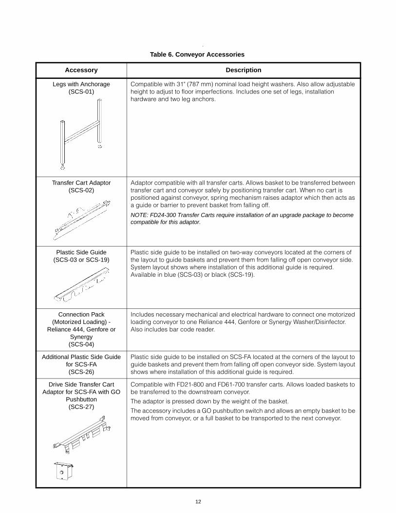
Table 6. Conveyor Accessories
Accessory Description
Legs with Anchorage(SCS-01)
Compatible with 31" (787 mm) nominal load height washers. Also allow adjustable height to adjust to floor imperfections. Includes one set of legs, installation hardware and two leg anchors.
Transfer Cart Adaptor(SCS-02)
Adaptor compatible with all transfer carts. Allows basket to be transferred between transfer cart and conveyor safely by positioning transfer cart. When no cart is positioned against conveyor, spring mechanism raises adaptor which then acts as a guide or barrier to prevent basket from falling off.
NOTE: FD24-300 Transfer Carts require installation of an upgrade package to become compatible for this adaptor.
Plastic Side Guide(SCS-03 or SCS-19)
Plastic side guide to be installed on two-way conveyors located at the corners of the layout to guide baskets and prevent them from falling off open conveyor side. System layout shows where installation of this additional guide is required. Available in blue (SCS-03) or black (SCS-19).
Connection Pack(Motorized Loading) -
Reliance 444, Genfore or Synergy(SCS-04)
Includes necessary mechanical and electrical hardware to connect one motorized loading conveyor to one Reliance 444, Genfore or Synergy Washer/Disinfector. Also includes bar code reader.
Additional Plastic Side Guide for SCS-FA(SCS-26)
Plastic side guide to be installed on SCS-FA located at the corners of the layout to guide baskets and prevent them from falling off open conveyor side. System layout shows where installation of this additional guide is required.
Drive Side Transfer Cart Adaptor for SCS-FA with GO
Pushbutton(SCS-27)
Compatible with FD21-800 and FD61-700 transfer carts. Allows loaded baskets to be transferred to the downstream conveyor.
The adaptor is pressed down by the weight of the basket.
The accessory includes a GO pushbutton switch and allows an empty basket to be moved from conveyor, or a full basket to be transported to the next conveyor.
12

GO Pushbutton for SCS-FA (SCS-28)
The GO pushbutton accessory has two functions:
1. Allows the operator to fill an empty basket with items directly on the conveyor and to decide when to put the basket back in circulation in the conveyor line.
2. Allows the operator to control the circulation of the basket over the SCS-FA conveyor.
Transfer Cart Adaptor for Non-Motorized Side on SCS-FA
with GO pushbutton (SCS-29)
Compatible with all transfer carts. Allows empty baskets to be unloaded from the conveyor line to the transfer cart. When no cart is positioned against conveyor, spring mechanism raises adaptor which then acts as a guide or barrier to prevent basket from falling off.
This accessory includes a GO pushbutton switch and allows an empty basket to be removed from conveyor, or a full basket to be transported to the next conveyor.
Connection Pack (Non-Motorized Loading) - Reliance 444, Genfore or
Synergy(SCS-05)
Includes necessary mechanical and electrical hardware to connect one non-motorized loading conveyor to one Reliance 444, Genfore or Synergy Washer/Disinfector. Also includes bar code reader.
Connection Pack - Vision Multi-Chamber
(SCS-06)
Includes necessary mechanical and electrical hardware to connect one loading conveyor (motorized or non-motorized) and one unloading conveyor (motorized or non-motorized) to one Reliance/Hamo Vision Multi-Chamber Washer/Disinfector.
Seismic Anchorage Pack(SCS-07)
Hardware to anchor one set of legs to meet seismic requirements for installation in regions prone to earthquakes. Refer to Seismic Anchorage Report (920-507-203) for details.
Electrical PowerSupply
(SCS-08)
Electrical power supply required to produce 24 Vdc for up to four motorized conveyors and/or non-motorized conveyors with feed-out. Installation kit contains one electrical power supply box, two supports, 125 ft (38 m) of electrical cable and four connectors (for 24 Vdc). Cable is to be cut to length and used exclusively to connect electrical power supply to the conveyor(s).
Pressure-ReleasePushbutton(SCS-09)
Includes one pressure-release pushbutton and pneumatic hoses to be installed on one SCS-FO or one SCS-2W-FO conveyor interfaced with either a Reliance 444 or Reliance 450 Unit.
Drain Flexible HoseConnection Pack
(SCS-10)
Includes one flexible hose (3/4" dia) and necessary hardware for drain connection of up to four conveyors.
Connection Pack (Non-Motorized Loading and Non-Motorized Unloading) to One
Reliance 444, Genfore or Synergy(SCS-11)
Includes necessary mechanical and electrical hardware to connect one non-motorized loading conveyor and one non-motorized unloading conveyor to one Reliance 444, Genfore or Synergy Washer/Disinfector. Also includes bar code reader.
Table 6. Conveyor Accessories (Cont’d)
Accessory Description
13
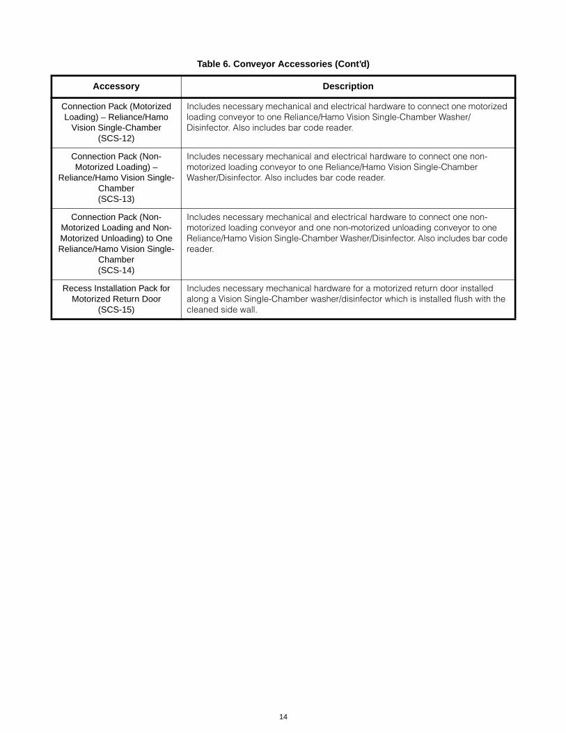
Connection Pack (Motorized Loading) – Reliance/Hamo
Vision Single-Chamber(SCS-12)
Includes necessary mechanical and electrical hardware to connect one motorized loading conveyor to one Reliance/Hamo Vision Single-Chamber Washer/Disinfector. Also includes bar code reader.
Connection Pack (Non-Motorized Loading) –
Reliance/Hamo Vision Single-Chamber(SCS-13)
Includes necessary mechanical and electrical hardware to connect one non-motorized loading conveyor to one Reliance/Hamo Vision Single-Chamber Washer/Disinfector. Also includes bar code reader.
Connection Pack (Non-Motorized Loading and Non-Motorized Unloading) to One Reliance/Hamo Vision Single-
Chamber(SCS-14)
Includes necessary mechanical and electrical hardware to connect one non-motorized loading conveyor and one non-motorized unloading conveyor to one Reliance/Hamo Vision Single-Chamber Washer/Disinfector. Also includes bar code reader.
Recess Installation Pack for Motorized Return Door
(SCS-15)
Includes necessary mechanical hardware for a motorized return door installed along a Vision Single-Chamber washer/disinfector which is installed flush with the cleaned side wall.
Table 6. Conveyor Accessories (Cont’d)
Accessory Description
14

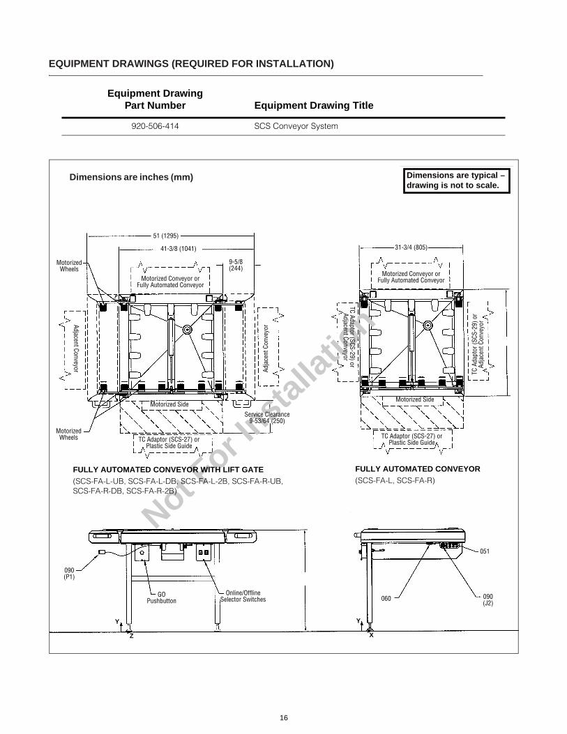
EQUIPMENT DRAWINGS (REQUIRED FOR INSTALLATION)
Equipment Drawing Part Number Equipment Drawing Title
920-506-414 SCS Conveyor System
Not For In
stallatio
n
Dimensions are typical –drawing is not to scale.
Dimensions are inches (mm)
Service Clearance
10 (254)
2 (51)
32 (813) 31 (787)
97 (2464)
161 (4090)
2 (51)
Optional Conveyor for Double Load
2 (51)
Power SupplyLocation for
Single Unload
Power SupplyLocation for
Double Unload
2 (51)
31 (787)
Optional Conveyorfor Double Unload
LOAD SIDE UNLOAD SIDE
444/450/Synergy/Genfore
/Vision SCWasher
444/450/Synergy/GenforeWasher
LOAD AND UNLOAD
CONVEYORS
NOTES
1. Conveyors are designed to give optimal results in an indoor environment where the temperature is maintained between 41-104°F (5-40°C) and maximum relative humidity is 80% for temperatures up to 88°F (31°C) decreasing linearly to 50% relative humidity at 104°F (40°C).
2. Workflow arrows affixed under each conveyor must point in correct direction.
3. STERIS recommends shutoff valves (not provided by STERIS) be installed on air lines and disconnect switches (not provided by STERIS) be installed on electrical supply lines.
4. Clearances shown are minimal for installing and servicing the SCS Load/Unload Conveyors.
5. Always follow local electrical and plumbing codes and safety-related work practices.
6. Customer must ensure conveyor stands on a noncombustible, non-slip, level floor.
7. Height adjustment (range) is 29 to 33" (737 to 838 mm).
8. Each conveyor is individually connected (in parallel).
9. Customers must decide if drains are required and what type of connections are required.
15
Not For I
nstall
atio
n
Dimensions are inches (mm) Dimensions are typical –drawing is not to scale.
51 (1295)
41-3/8 (1041)
Motorized Wheels
Motorized Conveyor or Fully Automated Conveyor
Adjacent Conveyor Adja
cent
Con
veyo
r
Motorized Side
TC Adaptor (SCS-27) or Plastic Side Guide
Motorized Wheels
Service Clearance9-53/64 (250)
9-5/8 (244)
31-3/4 (805)
Motorized Conveyor or Fully Automated Conveyor
Motorized Side
TC Adaptor (SCS-27) or Plastic Side Guide
TC Adaptor (SCS-29) or Adjacent Conveyor
TC A
dapt
or (S
CS-2
9) o
r Ad
jace
nt C
onve
yor
090 (P1)
GO Pushbutton
Online/Offline Selector Switches 060 090
(J2)
051
Y
Z
Y
X
FULLY AUTOMATED CONVEYOR WITH LIFT GATE(SCS-FA-L-UB, SCS-FA-L-DB, SCS-FA-L-2B, SCS-FA-R-UB, SCS-FA-R-DB, SCS-FA-R-2B)
FULLY AUTOMATED CONVEYOR(SCS-FA-L, SCS-FA-R)
EQUIPMENT DRAWINGS (REQUIRED FOR INSTALLATION)
Equipment Drawing Part Number Equipment Drawing Title
920-506-414 SCS Conveyor System
16

17
Not For I
nstall
atio
n
Dimensions are typical –drawing is not to scale.Dimensions are typical –drawing is not to scale.
Dimensions are inches (mm)
Service Clearance10
(254)
Motorized Wheels
Washer Unitor Adjacent Conveyor
Feed-In Cylinderfor Motorized
Conveyors(SCS-M-FI)
Washer Unit orTransfer Cart Adaptoror Adjacent Conveyor
Transfer Cart Adaptoror Adjacent Conveyor
Tran
sfer
Car
t Ada
ptor
or A
djac
ent C
onve
yor
Washer Unit orTransfer Cart Adaptoror Adjacent Conveyor
Washer Unit orTransfer Cart Adaptoror Adjacent Conveyor
31-3/4(806)
31-3/4(806)
24 x 24 (610 x 610)Rack
2 (51) Service Clearance If a Transfer Cart Adaptor Is Installed
31 (787)
Mot
orize
d Si
de
Feed-Out Cylinder for Motorized Conveyors
(SCS-M-FO)
31-3/4 (806)31-3/4 (806)
26 (660)Maximum
Load Height
Motorized Conveyor
(SCS-BM, SCS-M-FI, SCS-M-FO)
Non-Motorized Conveyor
(SCS-BM, SCS-M-FI, SCS-M-FO)
Feed-Out Cylinderfor Non-Motorized
Conveyors(SCS-FO)
EQUIPMENT DRAWINGS (REQUIRED FOR INSTALLATION)
Equipment Drawing Part Number Equipment Drawing Title
920-506-414 SCS Conveyor System

EQUIPMENT DRAWINGS (REQUIRED FOR INSTALLATION)
Equipment Drawing Part Number Equipment Drawing Title
920-506-414 SCS Conveyor System
Not For Installation
Dimensions are typical –drawing is not to scale.
Dimensions are inches (mm)
31-3/4 (806)
19-5/8 (498)
34 (864) 31-3/4 (806)
7-7/8 (200)
34 (864)
(SCS-SE) (SCS-SE-LG)(SCS-E) (SCS-E-LG)
ExtensionConveyors
Short ExtensionConveyors
NOTES
1. Conveyors are designed to give optimal results in an indoor environment where the temperature is maintained between 41-104°F (5-40°C) and maximum relative humidity is 80% for temperatures up to 88°F (31°C) decreasing linearly to 50% relative humidity at 104°F (40°C).
2. Workflow arrows affixed under each non two-way conveyor must point in correct direction.
3. STERIS recommends shutoff valves (not provided by STERIS) be installed on air lines and disconnect switches (not provided by STERIS) be installed on electrical supply lines.
4. Clearances shown are minimal for installing and servicing the SCS Conveyor System.
5. Always follow local electrical and plumbing codes and safety-related work practices.
6. Customer must ensure conveyor stands on a noncombustible, non-slip, level floor.
7. Height adjustment (range) is 29 to 33" (737 to 838 mm).
8. Maximum of four powered conveyors per power supply. Each conveyor is individually connected (in parallel).
9. Customers must decide if drains are required and what type of connections are required.
10. Expert Systems Planners from STERIS must assist in designing a configuration to an existing or new system focusing on the most efficient use of space.
UTILITY REQUIREMENTS
NOTE: Refer to Equipment Drawing 920-506-414 for installation details and specifications.
Weight:
• Maximum conveyor operating weight (including basket/rack and load weight) is 135 lb (61 kg)
• Shipping weight for non-motorized conveyors is 60 lb (27 kg)
• Shipping weight for motorized conveyors is 94 lb (43 kg)
• Shipping weight for fully automated conveyors is 130 lb (59 kg)
Air (Connected to Washer Supply):
• 1/4" NPT (1/4" BSPT), 80 (dynamic) to 125 (static) psig (550-860kPa). Refer to appropriate Tech Data (SD553, SD786, SD855, SD856, SD867, SD895, SD896 and SD880).
• Operating consumption of 1 scfm (1.8 m3/min). Refer to washer technical data.
Drain:
• 1-1/4" (32 mm). See NOTES.
Electricity:
• 100 V, one-phase, 60 Hz, 15 Amp
• 200-240 V, one-phase, 50/60 Hz, 15 Amp
• 200-480 V, three-phase, 50/60 Hz, 15 Amp
CUSTOMER IS RESPONSIBLE FOR COMPLIANCE WITHAPPLICABLE LOCAL AND NATIONAL CODES ANDREGULATIONS.The base language of this document is ENGLISH. Any translations must be made from the base language document.
18

Healthcare
Capital Equipment
19

For Further Information, contact:
STERIS Corporation5960 Heisley RoadMentor, OH 44060-1834 • USA440-354-2600 • 800-548-4873www.steris.com
This document is intended for the exclusive use of STERIS Customers, including architects or designers. Reproduction in whole or in part by any party other than a Customer is prohibited.SD857 ©2010, STERIS Corporation. All rights reserved. (05/01/10)