screen wall:cmu w/ brick veneer - denvergov.org · dwelling units within which fuel-fired...
TRANSCRIPT


A1.0
REV DATE ISSUE
2031 GROVE STREETDENVER, CO 80211303 . 333 . 1550www.kungarch.com
SCALE
DRAWING TILE
PROJECT NO.
AS NOTED
STRUCTURAL:S2E CONSULTINGSTRUCTURAL ENGINEERS5552 EAST 117th CIRCLETHORNTON, CO 80233303 . 252 . 0471
Ren
ovat
ions
For
:W
ESTE
RG
AAR
D/B
RIG
MAN
RES
IDEN
CE
3319
W. 2
9th
AVEN
UE
DEN
VER
, CO
802
11
OWNER REVIEWLANDMARK SUBMITTAL
10.06.1701.03.18
17-16
a r c h i t e c t u r e
SYMBOLS LEGEND:
CODE INFORMATION:APPLICABLE CODE:2015 INTERNATIONAL RESIDENTIAL CODE2016 DENVER AMENDMENTS2012 INTERNATIONAL ENERGY CONSERVATION CODE
CARBON MONOXIDE: HARD WIREDDETECTOR
SMOKE DETECTOR: HARD WIRED
SEE SITE OPEN SPACE ANALYSIS ON SHEET A1.1
PRESCRIPTIVE PATH RESIDENTIAL ENERGY COMPLIANCE:
XAX.X
XAX.X
XAX.X
XAX.X
XAX.X
A-1
1
2
3
4INTERIORELEVATIONREFERENCE
BUILDING ELEVATIONREFERENCE
BUILDING SECTION
WALL SECTION
DETAIL REFERENCE
DRAWING INDEX:A1.0 COVER SHEETA1.1 SITE & DEMOLITION PLANSA2.1 FLOOR & ROOF PLANSA3.1 BUILDING ELEVATIONSA4.1 BUILDING & WALL SECTIONS
NOTE TO CONTRACTOR:A. CONTRACTOR TO FIELD VERIFY ALL DIMENSIONS BEFORE
STARTING CONSTRUCTION.
B. DO NOT SCALE DRAWINGS.
C. PERSPECTIVES ON COVER SHEET ARE FOR ILLUSTRATIONPURPOSES ONLY. DO NOT BUILD FROM THESE PERSPECTIVES.
D. PROVIDE ALL NECESSARY AND PROPER BLOCKING, SUBSTRATE,ATTACHMENTS, BLOCK OUTS AND MISCELLANEOUS ITEMS AS MAYBE REQUIRED OR REASONABLY INFERRED, WHETHER SHOWN ORNOT SHOWN IN THE DOCUMENTS, FOR THE PROPER INTEGRATIONAND COMPLETION OF THE WORK.
E. CONTRACTOR TAKE SPECIAL NOTE OF FLOOR ELEVATIONS &FLOOR FINISHES & THE EFFECT ON OTHER CONSTRUCTIONINCLUDING BUT NOT LIMITED TO TOTAL STAIR RISE, CEILINGHEIGHTS, DOOR JAMB AND THRESHOLD CONFIGURATIONS,DOOR HEAD HEIGHT, LENGTH OF MECHANICAL ANDELECTRICAL FLOOR PENETRATIONS, ETC.
F. REASONABLE AND DILIGENT EFFORT HAS BEEN MADE TOCOORDINATE THESE DOCUMENTS w/ DOCUMENTS PREPARED BYALL THE ENGINEERS. HOWEVER IT IS THE RESPONSIBILITY OF THEGENERAL CONTRACTOR TO THOROUGHLY REVIEW ALL DOCUMENTSAND BRING ANY DISCREPANCY TO THE ATTENTION OF THEARCHITECT FOR RESOLUTION PRIOR TO BEGINNING WORK.
GENGERAL NOTES:1. ALL ASPECTS OF PROJECT ARE TO COMPLY w/ THE CURRENT INTERNATIONAL
RESIDENTIAL CODE
2. ALL LOCAL CODES, ZONING & COVENANTS NOTCOVERED IN PLANS MUST BECONFORMED TO.
3. WINDOW(S) IN BEDROOM AREAS TO MEET MINIMUMEGRESS ~ 5.7 SQFT OF OPENING,WITH A CLEAR WIDTH OF 20" & A HEIGHT OF 24".
4. ALL GUARDRAIL TO BE MIN. 36" HIGH w/ SPINDLES MAX. 4" O.C. OR 34" ON SIDES OFSTAIRS MEASUREDVERTICALLY FROM NOSING.
5. HARD WIRED SMOKE DETECTORS SHALL BE INSTALLED IN EACH SLEEPING ROOM,OUTSIDE OF EACH SLEEPING AREA, AND ON EACH LEVEL.
6. HARD WIRED CARBON MONOXIDE ALARM TO BE INSTALLED OUTSIDE OF EACHSEPARATE SLEEPING AREA IN THE IMMEDIATE VICINITY OF THE BEDROOMS INDWELLING UNITS WITHIN WHICH FUEL-FIRED APPLIANCES ARE INSTALLED AND INDWELLING UNITS THAT HAVE ATTACHED GARAGE.
7. ALL GLAZING IN DOORS & SHOWER ENCLOSURES TO BE TEMPERED.
8. MAXIMUM LEVEL CHANGE FOR THE EXIT DOORS TO EXTERIOR LANDING TO BE 7 3/4".
9. THE PRESSURE RELIEF VALVE FOR THE WATER HEATER, AC CONDENSATE DRAIN, ORFURNACE HUMIDIFIER DRAIN MUST DISCHARGE TO AN APPROVED RECEPTOR.
10. FLOOR DRAINS MUST BE OF THE DEEP SEAL DESIGN WITH A LIQUID SEAL OF 2” TO 4”OR A TRAP PRIMER.
11. ALL ELECTRICAL RECEPTACLES LOCATED IN BATHROOMS, GARAGES, OUTDOORS,CRAWL SPACES, UNFINISHED BASEMENT AREAS, KITCHENS SERVING THECOUNTERTOPS, WITHIN 6’-0” OF THE OUTSIDE EDGE OF WET BAR SINKS MUST BE GFCIPROTECTED. GFCI PROTECTION IS ALSO REQUIRED FOR ALL ELECTRICAL EQUIPMENTASSOCIATED WITH JETTED BATHTUBS.
12. BRANCH CIRCUITS SUPPLYING ALL ELECTRICAL OUTLETS LOCATED IN BEDROOMS ANDCLOSETS ACCESSED FROM BEDROOMS MUST BE PROTECTED BY AN ARC-FAULTCIRCUIT-INTERRUPTER LISTED TO PROVIDE PROTECTION OF THE ENTIRE BRANCHCIRCUIT.
13. PROVIDE SCHEDULE 80 PVC RIGID CONDUIT FOR UNFINISHED BASEMENT WIRING.
14. UFER GROUND: A MIN. 20'-0" LENGTH OF ELECTRICALLY CONDUCTIVE NO. 4REINFORCING BAR ENCASED BY AT LEAST 2" CONCRETE AND LOCATED NEAR THEBOTTOM OF A CONCRETE FOUNDATION.
15. THE REQUIRED BACKING MATERIAL FOR ALL SHOWERS AND TUB/SHOWERCOMBINATION FIXTURES MUST BE WATER-RESISTANT TO A MINIMUM HEIGHT OF 6’0”.FLOORS AND WALLS MUST HAVE A NONABSORBENT FINISH. CEMENT, FIBER-CEMENT,OR GLASS MAT GYPSUM BACKERS MUST BE USED FOR CERAMIC TILE APPLICATIONS.
16. THE REQUIRED EXIT DOOR MAY ONLY HAVE A SINGLE RISER (MAXIMUM 7¾” FROM THETOP OF THE THRESHOLD) TO A SURFACE QUALIFYING AS A LANDING. AN EXTERIORLANDING IS REQUIRED AT NO MORE THAN TWO RISERS (MAXIMUM 7¾”) BELOW OTHEREXTERIOR DOOR THRESHOLDS.
17. FUEL-FIRED EQUIPMENT (FURNACE, WATER HEATER, ETC) MUST BE PROVIDED WITHADEQUATE OUTSIDE COMBUSTION AIR. A MINIMUM OF TWO DUCTS OR OPENINGS ISREQUIRED: ONE WITHIN 12” OF THE CEILING AND ONE WITHIN 12” OF THE FLOOR. THEMINIMUM SIZE OF THE DUCTS IS DETERMINED BY THE COMBINED BTU RATINGS OFTHE EQUIPMENT SERVED: 1 SQUARE INCH PER 2,000 BTU/H (FOR HORIZONTAL DUCTS).
18. PROVIDE WINDOWS WITH MIN. OF INSULATED DOUBLE PANE WITH MAX. U-FACTOR 0.32
19. ROOF TRUSS SHOP DRAWINGS WILL BE A DEFERED SUBMITTAL.
WINDOWU-FACTOR
SKYLIGHTU-FACTOR
CEILINGR-VALUE
WOODFRAME WALL
R-VALUE
MASSWALL
R-VALUE
FLOORR-VALUE
BASEMENTWALL
R-VALUE
SLABR-VALUE
0.32 0.55 R-49 R-20 R-13/17 R-30 R-15/19 R-10, 2FT
DESIGN CRITERIA PER 2015 IECC SECTION R401-R404 / IRC SECTION N1101.1-N1104(ALL R-VALUES ILLUSTRATE MINIMUMS - ALL U-VALUES ILLUSTRATE MAXIMUMS)
CLIMATE ZONE 5B
CRAWLSPACE WALL
R-VALUE
R-15/19
1. HEATING AND COOLING SYSTEM TO BE FORCED AIR. WATER-HEATING SYSTEM TO BE NATURAL GAS HEAT TANK. ALL EQUIPMENT TO ENERGY STAR RATED.2. PROVIDE PROGRAMMABLE THERMOSTAT PER EACH SEPARATE HEATING AND COOLING SYSTEM.3. SEAL ALL DUCTS, AIR HANDLERS AND FILTER BOXES PER 2015 IRC SECTION M1601.4.1.
N.I.C. NOT IN CONTRACTN.T.S. NOT TO SCALEOPP. OPPOSITEP.T. PRESSURE TREATEDR.O. ROUGH OPENINGRTU ROOF TOP UNITSIM. SIMILARS.S. STAINLESS STEELT&G TONGUE AND GROOVET.O.M. TOP OF MASONRYT.O.S. TOP OF STEELT.O.W. TOP OF WALLTS TUBE STEELTYP. TYPICALV.I.F. VERIFY IN FIELDVERT. VERTICALw/ WITHW/D WASHER & DRYERW.H. WATER HEATERXPS EXTRUDED POLYSTYRENE
ABBREVIATIONS:@ AT& ANDA.F.F. AFTER FINISH FLOORC CENTER LINECLR. CLEARCONC. CONCRETEC.J. CONTROL JOINTdia. DIAMETERD.F. DRINKING FOUNTAIND.S. DOWNSPOUTE.C. EVAPORATIVE COOLEREQ. EQUALF.D. FLOOR DRAINF.E. FIRE EXTINGUISHERF.F.E. FINISH FLOOR ELEVATIONF.O.M. FACE OF MASONRYHGT. HEIGHTH.M. HOLLOW METALHORIZ. HORIZONTALLVL. LAMINATED VENEER LUMBERMAX. MAXIMUMMIN. MINIMUMM.R. MOISTURE RESISTANT
L
PARTITION LEGEND
EXTERIOR WALL:2X6 STUD FRAMING @ 16" O.C.INTERIOR - 1/2" GYP. BOARD ON VAPOR BARIER.EXTERIOR - EXTERIOR FINISH ON TYVEK HOUSE
WRAP ON OSB SHEATHING.
1-HR DWELL SEPARATION WALL:UL DESIGN NO. U-370 - SEE SHEET A2.1 FORSPECIFICATION.
EXTERIOR WALL (GAME ROOM):2X6 STUD FRAMING @ 16" O.C. w/ R-21 BATT
INSULATION IN BETWEEN.INTERIOR - 1/2" GYP. BOARD ON VAPOR BARIER.EXTERIOR - EXTERIOR FINISH ON TYVEK HOUSE
WRAP ON OSB SHEATHING.
EXISTING MASONRY WALL:
EXISTING INTERIOR PARTITION:
INTERIOR PARTITION:2X4 STUD FRAMING @ 16" O.C. w/ 1/2" GYP. BOARD
ON BOTH SIDES. PROVIDE M.R. GYP. BOARDIN BATHROOMS.
RENOVATIONS FOR:WESTERGAARD/BRIGMAN RESIDENCE
OWNER:
CHANDRA WESTERGAARD3319 W. 29th AVENUEDENVER, CO [email protected]
ARCHITECT:
KUNG ARCHITECTURE2031 GROVE STREETDENVER, CO 80211303 . 333 . [email protected]
VICINITY MAP:NOT TO SCALE
PROJECT SITE
COVER SHEET
STRUCTURAL:
S2E CONSULTINGSTRUCTURAL ENGINEERS5552 EAST 117 th CIRCLETHORNTON, CO 80233303 . 252 . 0471
3319 W. 29th AVENUEDENVER, CO 80211

A1.1
REV DATE ISSUE
2031 GROVE STREETDENVER, CO 80211303 . 333 . 1550www.kungarch.com
SCALE
DRAWING TILE
PROJECT NO.
AS NOTED
STRUCTURAL:S2E CONSULTINGSTRUCTURAL ENGINEERS5552 EAST 117th CIRCLETHORNTON, CO 80233303 . 252 . 0471
Ren
ovat
ions
For
:W
ESTE
RG
AAR
D/B
RIG
MAN
RES
IDEN
CE
3319
W. 2
9th
AVEN
UE
DEN
VER
, CO
802
11
OWNER REVIEWLANDMARK SUBMITTAL
10.06.1701.03.18
17-16
a r c h i t e c t u r e
ZONING CODE ANALYSIS:
ZONING U-SU-B
BUILDING FORM URBAN HOUSE
# OF DWELLLING UNITS 1REQ. OFF-STREET PARKING 0PROVIDED OFF-STREET PARKING 2
CAR ACCESS EXISTING DRIVEWAY FROM ALLEY
SITE OPEN SPACE ANALYSIS:
TOTAL ZONE LOT AREA 5,355 SQFT
ALLOWABLE BUILDING COVERAGE - 37.5% = 2,008 SQFT
EXISTING COVERAGE BY STRUCTURE: HOUSE 886 SQFT REAR COVERED PORCH 558 SQFT ADU 416 SQFT
TOTAL 1,860 SQFT
RENOVATION IS TO ENCLOSE EXISTING REAR COVERED PORCH.
COVERAGE AFTER THE RENOVATION = 1,860 SQFT
ALLEN M. GHOST HISTORIC DISTRICT
29'-0
"
6.30'1.0'
23'-0
"3'
-0"
0.7'
45'-3
"13
'-0"
58'-3
"
ADJACENTBUILDING
ADJACENTBUILDING
ADJACENTBUILDING
ADJACENTBUILDING
WASTE
EXISTING2-STORYRESIDENCE
42.5' PROPERTY LINE
42.5' PROPERTY LINE
126'
PR
OPE
RTY
LIN
E
126'
PR
OPE
RTY
LIN
E
SETBACKF.O. FINISHSETBACK
F.O. FINISH
PRIM
NAR
Y ST
REE
TSE
T BA
CK
SETBACK
EXISTINGCONDENSERUNIT
EL. 5357.2' EL. 5356.4'
EL. 5359.56'
EXTEND ADJACENT6'-0" h. CEDAR FENCE(6" VERTICAL PICKETS)
SLO
PE
EL. 5358.60'
EXISTING ADU
DECK
PORCH
EXISTINGCELLARACCESS
4" THICK CONCRETEw/ BROOM FINISH
6'-0" h. CMU PIERw/ BRICK VENEER,TYP.
PARKING
8'-0" w.CARRIAGE DOOR
36" w. GATE8'-0" w.CARRIAGE DOOR
UP
UP
UP
UP
CITY SIDEWALK
WEST 29th AVENUE
LAWN AREA
RENOVATIONOF EXISTINGCOVERED PORCH
4A1.1
5A1.1
2A1.1
3A1.1
REMOVE EXISTINGFRAMED WALL w/DOOR & WINDOWS,TYP.
REMOVE EXISTINGRAILING, TYP.
REMOVE EXISTINGWINDOW & SILL WALL
REMOVE EXISTINGCEILING PANEL, TYP.
REMOVE EXISTINGSUB-FLOOR, TYP.
REMOVE EXISTINGPOST
(E) KITCHEN
(E) DINING
(E) LIVING
(E) LAUNDRY
(E) COVERED PORCH
REMOVEEXISTINGDOOR
REMOVE EXISTINGFRAMED WALL & WINDOW(57 SQFT)
REMOVE EXISTINGRAILING
REMOVE EXISTINGPOST
REMOVE EXISTINGFRAMED WALL(88 SQFT)
REMOVE EXISTINGRAILING
REMOVE EXISTINGRAILING
REMOVE EXISTINGFRAMED WALL & WINDOW(92 SQFT)
REMOVE EXISTINGRAILING
REMOVE EXISTINGWINDOW & SILL WALL
ZONING DEMOLITION REQUIREMENTS:
TOTAL EXISTING EXTERIOR WALL SURFACE = 1,778 SQFT.TOTAL EXTERIOR WALL TO BE REMOVED = 237 SQFT = 13%.
The owner of the subject property attests and understands theexisting structure shown on this plan is categorized as a CompliantStructure per Denver Zoning Code, Division 12.6, and or categorizedas a Nonconforming Structure per Denver Zoning Code, Division 12.8,and as such, demolition of 40% or more of the square footage (area)of the structure’s exterior walls as a result of construction activities willrequire new or revised zoning/building plans documenting fullcompliance with all applicable zone district standards.”
1A1.1
6A1.1
4A1.1
2A1.1
5A1.1
3A1.1
SITE &DEMOLITION
PLANS
SCALE: 1/8" = 1'-0" SITE PLAN
NSCALE: 1/4" = 1'-0" DEMOLITION PLAN
N
SCALE: 1/8" = 1'-0" WEST ELEVATION DEMOLITION
SCALE: 1/8" = 1'-0" SOUTH ELEVATION DEMOLITION
SCALE: 1/8" = 1'-0" EAST ELEVATION DEMOLITION
SCALE: 1/8" = 1'-0" NORTH ELEVATION DEMOLITION
TOTAL EXISTING EXT. WALL - 495 SQFT
TOTAL EXISTING EXT. WALL - 445 SQFTTOTAL EXISTING EXT. WALL - 556 SQFT
TOTAL EXISTING EXT. WALL - 282 SQFT

A2.1
REV DATE ISSUE
2031 GROVE STREETDENVER, CO 80211303 . 333 . 1550www.kungarch.com
SCALE
DRAWING TILE
PROJECT NO.
AS NOTED
STRUCTURAL:S2E CONSULTINGSTRUCTURAL ENGINEERS5552 EAST 117th CIRCLETHORNTON, CO 80233303 . 252 . 0471
Ren
ovat
ions
For
:W
ESTE
RG
AAR
D/B
RIG
MAN
RES
IDEN
CE
3319
W. 2
9th
AVEN
UE
DEN
VER
, CO
802
11
OWNER REVIEWLANDMARK SUBMITTAL
10.06.1701.03.18
17-16
a r c h i t e c t u r e
5'-0
" X7'
-0"
2'-6" X 7'-0"
2'-0" by 2'-0"
8'-0
" by
2'-6
"3'
-0" b
y4'
-0"
2A3.1
1A3.1
3A4.1
W/D
2A4.1
4A3.1
3A3.1
1A4.1
01
A
B
C
02
03
04
05
06
11'-6
1/4
"
4'-4" 23'-9"
2'-4"
3'-2
1/2
"2'
-6"
3'-6
"1'
-4"
1'-8
"
6'-0
1/2
"5'
-5"
3'-5"
6'-3 3/4" 9'-6 1/2"
4" 2'-0" 5'-4"7'-2"
3'-10 1/2" 4 1/2"
1'-1"
4 1/
2"13
'-11
3/4"
11'-1
1 3/
4"10
'-1"
36'-5
"
SEATINGLAUNDRY
MASTERBEDROOM
WALK-INCLOSET
M. BATH(E) KITCHEN
(E) DINING
(E) LIVING
23'-0" x 7'-6" 8-PANE PANORAMIC DOORS
9'-0
" x 7
'-6" 3
-PAN
EPA
NO
RAM
IC D
OO
RS
UP
UP
UP
UP
UP
UP
(E) PORCH
RELOCATION ELEC.METER & SWITCH GEAR EXISTING
ELEC.PANEL
EXISTINGBASEMENTACCESS
36" V
ANIT
Y36
" VAN
ITY
NEW DOUBLEDOOR IN EXISTINGOPENING
INFILLEXISTINGOPENING
UP
UP
2" 2'-0" 8'-2" 3'-4" 8'-2" 2'-0" 3'-7" 2'-0"
2'-0
"3'
-0"
EXISTINGADU
PRO
PER
TY L
INE
PROPERTY LINE
(2) 4'-0" X 5'-5" CARRIAGEDOOR w/ AUTO OPENER 3'-0" X 6'-0" GATE
(2) 4'-0" X 5'-5" CARRIAGEDOOR w/ AUTO OPENER
6'-0" h. CMU PIER w/BRICK VENEER, TYP.
6'-0" h. CEDAR FENCEw/ 6" VERTICAL PICKETS
T T T T T T T T TT T
CBA
TT
T
2'-0" 3'-0" 2'-0" 4'-0" 2'-0"2'
-0"
4'-0
" 2'-6
"
7'-6
"
23'-0" 9'-0"
7'-6
"
7'-0
"
7'-0
"
7'-0
"
3'-0" 2'-0" 2'-6" 3'-10 1/2"
7'-0
"
5'-0"
7'-0
" TY
P.
ACCESSDOOR
ACCESSDOOR
ALUMINUM PANORAMIC DOOR01 02
INTERIOR WOOD DOOR03 INTERIOR WOOD DOOR04 INTERIOR WOOD DOOR05
WINDOW: DOUBLE GLAZED w/ MAX. U-FACTOR 0.32. ALUMINUM CLAD WOOD WINDOWS:
SITELINE BY JELD-WEN COLOR - BRILLIANT WHITE
GENERAL PERFORMANCE REQUIREMENTS:A. THERMAL PERFORMANCE: COMPLY WITH NFRC100.B. AIR LEAKAGE, WATER RESISTANCE, STRUCTURAL
TEST: COMPLY WITH ANSI/AAMA 101/I.S.2.C. FORCED-ENTRY RESISTANCE: COMPLY WITH ASTM
E 588.
GLAZING:A. INSULATED GLASS UNITS: ASTM E 774, CLASS A, 7/8
INCH (22 MM) THICK OVERALLGLAZING TYPE:CLEAR/SUNCOAT® LOW-E EC
TOP OF WINDOW TO MATCH TOP OF DOOR ON ALL LEVELS,EXCEPT OTHERWISE NOTED.
INTERIOR DOOR: PAINTED 1 3/8" SOLID CORE SLAB
BIRCH VENEER DOOR.
PANORAMIC DOOR:
COLOR - WHITE
BY PANORAMICDOORS.COM MODEL SIGNATURE ALUMINUM. LOW-E3 INSULATED GLASS.
CASEMENTCASEMENTCASEMENT
FIXED
ALUMINUM PANORAMIC DOOR
3 EQUAL PARTS8 EQUAL PARTS
V.I.F.
PATIO DOOR06
PATIO SWINGING DOOR:CUSTOM WOOD BY JELD-WENCOLOR - BRILLIANT WHITE
2A2.1
3A2.1
1A2.1
4A2.1 T
GARDEN &UPPER LEVELFLOOR PLANS
SCALE: 1/4" = 1'-0" MAIN LEVEL FLOOR PLAN
NSCALE: 1/8" = 1'-0" ROOF PLAN
N
EXISTING ROOF, TYP.- NO WORK PROVIDED
SCALE: 1/4" = 1'-0" SCREEN WALL PLAN
N
SCALE: 1/4" = 1'-0" WINDOW/DOOR ELEVATION
= TEMPERED GLASS

A3.1
REV DATE ISSUE
2031 GROVE STREETDENVER, CO 80211303 . 333 . 1550www.kungarch.com
SCALE
DRAWING TILE
PROJECT NO.
AS NOTED
STRUCTURAL:S2E CONSULTINGSTRUCTURAL ENGINEERS5552 EAST 117th CIRCLETHORNTON, CO 80233303 . 252 . 0471
Ren
ovat
ions
For
:W
ESTE
RG
AAR
D/B
RIG
MAN
RES
IDEN
CE
3319
W. 2
9th
AVEN
UE
DEN
VER
, CO
802
11
OWNER REVIEWLANDMARK SUBMITTAL
10.06.1701.03.18
17-16
a r c h i t e c t u r e
1.0' 17'-0
"
30'-0
" M
AX. H
EIG
HT
6.30'
45.0°
MASTER SUITET.O. SUB-FLOOR-0'-6" (EXISTING)
EXISTING ROOFING& STRUCTURETO REMAIN
BULK PLANE
BULK PLA
NE
BULK PLANE
PRO
PER
TY L
INE
PRO
PER
TY L
INE
MAIN LEVEL(EXISTING)0'-0" (EL. 5362.16')
EL. 5358.7'
EL. 5359.3'FRONT PRIMARYBASE PLANE
2X6 STUD FRAMEWALL INFILL BETWEENEXISTING STRUCTURE
BRICK VENEER
EL. 5359.9'EL. 5356.8'FRONT PRIMARYBASE PLANE
SETBACK
SETBACKF.O. FINISH
MATCH BRICKCORBEL BENDw/ EXISTING
MAIN LEVEL(EXISTING)0'-0"
MASTER SUITE LEVELT.O. SUB-FLOOR(MATCH EXISTING)-0'-6"
4" CEMENTITIOUSLAP SIDING
2X6 STUD FRAMEWALL INFILL BETWEENEXISTING STRUCTURE
EXISTING ROOFING& STRUCTURETO REMAIN
MASTER SUITE LEVELT.O. SUB-FLOOR(MATCH EXISTING)-0'-6"
4" CEMENTITIOUSLAP SIDING
2X6 STUD FRAMEWALL INFILL BETWEENEXISTING STRUCTURE
EXISTING ROOFING& STRUCTURETO REMAIN
10'-0
"
17'-0
" M
AX. H
EIG
HT
6'-0
"
45.0°
CMU PIER w/ BRICKVENEER, TYP.
CEDAR CARRIAGEDOOR, TYP.
PRE-CAST CONCRETECAP, TYP.
EXISTING ADUBEYOND
BULK PLANE
BULK PLA
NE
BULK PLANE
PRO
PER
TY L
INE
PRO
PER
TY L
INE
REAR PRIMARYBASE PLANEEL. 5359.08'
EL. 5359.56'
EL. 5358.60'
EL. 5359.9'
REAR PRIMARYBASE PLANEEL. 5359.08'
SETBACKF.O. FINISH(0' REQ.)
MASTER SUITE LEVELT.O. SUB-FLOOR-0'-6" (EXISTING)
MAIN LEVEL(EXISTING)0'-0"
EXISTING ROOF& STRUCTURETO REMAIN
BRICK VENEER
2X6 STUD FRAMEWALL INFILL BETWEENEXISTING STRUCTURE
BRICK VENEER TOMATCH EXISTING
1A3.1
2A3.1
5A3.1
3A3.1
5A3.1
BUILDINGELEVATIONS
SCALE: 1/4" = 1'-0" SOUTH ELEVATION
SCALE: 1/4" = 1'-0" NORTH ELEVATION
SCALE: 1/4" = 1'-0" EAST ELEVATION
SCALE: 1/4" = 1'-0" WEST ELEVATION
SCALE: 1/4" = 1'-0" ROLLING DOOR ELEVATION

A4.1
REV DATE ISSUE
2031 GROVE STREETDENVER, CO 80211303 . 333 . 1550www.kungarch.com
SCALE
DRAWING TILE
PROJECT NO.
AS NOTED
STRUCTURAL:S2E CONSULTINGSTRUCTURAL ENGINEERS5552 EAST 117th CIRCLETHORNTON, CO 80233303 . 252 . 0471
Ren
ovat
ions
For
:W
ESTE
RG
AAR
D/B
RIG
MAN
RES
IDEN
CE
3319
W. 2
9th
AVEN
UE
DEN
VER
, CO
802
11
OWNER REVIEWLANDMARK SUBMITTAL
10.06.1701.03.18
17-16
a r c h i t e c t u r e3A4.1
MASTER SUITE LEVELT.O. SUB-FLOOR-0'-6"
EXISTING ROOF STRUCTURE
8 1/2" (R-51) CLOSED SPRAYFOAM INSULATION
EXISTING FLOOR STRUCTURE
NEW 3/4" SUB-FLOORGLUED & SCREWED
2X6 STUD FRAMING@ 16" O.C.
NEW FREEZE PROTECTIONGRADE BEAM
3A4.1
4A4.1
EXISTING RENOVATION
MASTER SUITE LEVELT.O. SUB-FLOOR-0'-6"
EXISTING ROOF STRUCTURE
8 1/2" (R-51) CLOSED SPRAYFOAM INSULATION
EXISTING FLOOR STRUCTURE
NEW 3/4" SUB-FLOORGLUED & SCREWED
2X6 STUD FRAMING@ 16" O.C.
NEW FREEZE PROTECTIONGRADE BEAM
OPP.HAND
2A4.1 1
A4.1
MASTER SUITE LEVELT.O. SUB-FLOOR-0'-6"
EXISTING ROOF STRUCTURE
8 1/2" (R-51) CLOSED SPRAYFOAM INSULATION
EXISTING FLOOR STRUCTURE
NEW 3/4" SUB-FLOORGLUED & SCREWED
2X6 STUD FRAMING@ 16" O.C.
NEW FREEZE PROTECTIONGRADE BEAM
7'-0
"
1'-4
"
4'-0
"
MASTER SUITE LEVELT. O. SUB-FLOOR-0'-6"
TYVEK HOUSE WRAP
OSB SHEATHINGPER STRUCTURAL
2X6 STUD @ 16" O.C.
R-21 BATT INSULATION
VAPOR BARRIER
1/2" GYP. BOARD
TYPICAL EXTERIORWALL CONSTRUCTION
EXISTING ROOFING
EXISTING DECKING
EXISTING RAFTER
1/2" GYP. BOARD CEILING
P.T. BASE PLATEON SILL SEAL
1X6 MDF BASE
NEW 3/4" SUB-FLOOR
EXISTING FLOOR JOIST
FREEZE PROTECTIONGRADE BEAM
4" RIGID INSULATION,TYP.
METAL FLASHING &WEEP HOLE @ 16" O.C.
APPROXIMATEGRADE
NEW PRE-FINISHEDMETAL GUTTER &DOWNSPOUT
BRICK VENEER
MASONRY TIE @16" O.C., TYP.
T. O. WINDOW
MIN
.
NEW R-30 BATT INSULATION
CONTINUOUS CLASS 1VAPOR BARRIER
8 1/2" (R-51) CLOSEDSPRAY FOAM INSULATION
4" CEMENTITIOUSLAP SIDING
PRE-FINISHEDMETAL FLASHING
BRICK CORBEL TOMATCH EXISTING
EXISTING BEAM
1A4.1
2A4.1
2A4.1
4A4.1
SCALE: 1/4" = 1'-0" BUILDING SECTION
SCALE: 1/4" = 1'-0" BUILDING SECTION
BUILDING & WALLSECTIONS
SCALE: 1/4" = 1'-0" BUILDING SECTION
SCALE: 3/4" = 1'-0" WALL SECTION

SECTION 08 16 14.00 ALUMINUM EXTERIOR PANORAMIC DOOR SYSTEM
PART 1 GENERAL
1.1 SECTION INCLUDES
A. Fiberglass Exterior Doors and Sidelites
B. Prehung Systems
C. Glazing
1.2 REFERENCES
A. American Architectural Manufacturer Association (AAMA):
1. AAMA 1304; Voluntary Specification for Forced Entry Resistance of Side-Hinged Door Systems.
B. ASTM International:
1. ASTM E283; Standard Test Method for Determining Rate of Air Leakage Through Exterior Windows, Curtain Walls, and Doors Under Specified Pressure Differences Across the Specimen.
2. ASTM E330; Standard Test Method for Structural Performance of Exterior Windows, Doors, Skylights and Curtain Walls by Uniform Static Pressure Difference.
3. ASTM E331; Standard Test Method for Water Penetration of Exterior Windows, Skylights, Doors, and Curtain Walls by Uniform Static Air Pressure Difference.
4. ASTM E547; Standard Test Method for Water Penetration of Exterior Windows, Skylights, Doors, and Curtain Walls by Cyclic Static Air Pressure Difference.
5. ASTM E 1886; Standard Test Method for Performance of Exterior Windows, Curtain Walls, Doors, and Impact Protective Systems Impacted by Missile(s) and Exposed to Cyclic Pressure Differentials.
6. ASTM E 1996; Standard Specification for Performance of Exterior Windows, Curtain Walls, Doors and Impact Protective Systems Impacted by Windborne Debris in Hurricanes.
C. National Fenestration Rating Council (NFRC):
1. NFRC 100; Procedure for Determining Fenestration Product U-Factors. 2. NFRC 200; Procedure for Determining Fenestration Product Solar Heat Gain
Coefficient and Visible Transmittance at Normal Incidence. 1.3 SUBMITTALS
A. Submit under provisions of Section 0 13 00 – Administrative Requirements.
B. Product Data: Submit door manufacturer current product literature, including installation instruction.
C. Samples: Provide finish samples for all products.
D. Quality Assurance Submittals
1. Design Data: Provide manufacturer test report numbers indicating product compliance with indicated requirements.
2. Manufacturer Instructions: Provide manufacturer’s written installation instructions. E. Closeout Submittals: Refer to Section 0 17 00 Execution and Closeout Requirements
Closeout Submittals.
1.4 DELIVERY, STORAGE AND HANDLING
A. Deliver, store and handle materials and products in strict compliance with manufacturer's instructions and recommendations and industry standards.

B. Deliver and store assembly materials and components in manufacturer's original, unopened, undamaged containers with identification labels intact. Protect from damage.
1.5 WARRANTY
A. Manufacturer's Standard Warranty: Assemblies will be free from defects in materials and workmanship from the date of manufacture for the time periods indicated below:
1. Owner-Occupied Single Family Residence Limited Warranty a. 10 years for Wood and power coated panel and frame. b. Glazing: 10 years against seal breakage of Insulated Glass. And 10 years
against delamination of Laminated Glass. PART 2 PRODUCTT
2.1 MANUFACTURER
A. Acceptable Manufacturer: Panoramic Doors.; 2515 Industry Street, Oceanside, CA 92054; Tel: 760-722-1250; Email: [email protected]; Web: http://www.panoramicdoors.com.
2.2 ALUMINUM PANORAMIC DOORS - GENERAL
A. Materials:
1. Extruded aluminum. B. Installation Accessories:
1. Flashing: Refer to Section 07 60 00 - Flashing and Sheet Metal. 2. Sealants: OSI Sealants by Henkel Corporation. 3. Sealants: Refer to Section 07920 - Joint Sealants. 4. Sealants: Manufacturer recommended sealants to maintain watertight conditions.
C. Finishes
1. Interior Finishes for Patio Doors: a. Finish: Primed
2. Exterior Finishes for Patio Doors: a. AAMA 2605 Standard Colors:
1) Color: Apollo White. 2.3 ALUMINUM PANORAMIC DOOR ASSEMBLIES
A. Basis of Design: Signature Series aluminum patio door assemblies as manufactured by Panoramic Doors.
1. Patio Door Type: Slide and Pivot. B. Configurations:
1. Eight Door Configurations: Right Passage door. 2. Three Door Configurations: Left Pasage door.
C. Patio Door Fabrication:
1. Frame: Thermallhy Broken door with eeCore. 2. Glass: Mounted using silicone glazing compound on exterior and acrylic sealant on
interior. 3. Door Style: 3” Narrow Frame.
D. Door Panels:
1. Material: Thermal Break door with eeCore. 2. Thickness: 1-3/4 inch (44.4 mm). 3. Stiles and Rail:
a. 3” narrow frame. rails and stiles, E. Tracks: Top and bottom tracks to be 1”x2.71” flush track.
F. Weatherstripping: White.
G. Hardware:

1. Hinges/Flush Bolts Finish: Hidden hinge. 2. Locks: multi-point on passage door. Concealed multi-point for swing & pivot
panels. 3. Handle Set: Miami White.
a. Contemporary Handle Set Finish: Miami White. 4. Sill: Clear Anodized.
H. Glazing for Patio Doors:
1. Strength: Tempered glass. 2. Glazing Type: Insulated glass.
a. Description: Two panes of glass utilizing continuous roll formed stainless steel spacer and dual seal sealants.
b. Glass Coating: Low-E3. c. Air Space: Air-filled airspace with capillary tubes.
PART 3 EXECUTION 3.1 EXAMINATION AND PREPARATION
A. Inspect and prepare openings and substrates using the methods recommended by the manufacturer for achieving best result for the substrates under project conditions.
1. Inspect assembly components prior to installation. 2. Verify rough opening conditions are within recommended tolerances. 3. Form sheet metal sill pan in accordance with manufacturer's recommendations. 4. Prepare assembly components for installation in accordance with manufacturer's
recommendations. B. Do not proceed with installation until openings and substrates have been prepared using the
methods recommended by the manufacturer and deviations from manufacturer's recommended tolerances are corrected. Commencement of installation constitutes acceptance of conditions.
C. If preparation is the responsibility of another installer, notify Architect in writing of deviations from manufacturer's recommended installation tolerances and conditions.
3.2 INSTALLATION
A. Install assemblies in accordance with manufacturer's installation guidelines and recommendations including the following.
B. Installation of Patio Doors: Insert patio doors into rough opening.
1. Shim side jambs straight. 2. Inspect patio door for square, level and plumb. 3. Fasten patio door through frame around entire patio door. 4. Test and adjust for smooth operation of patio door.
3.3 FIELD QUALITY CONTROL
A. Manufacturers' Field Services: Perform field inspections as recommended by manufacturer.
3.4 CLEANING AND PROTECTION
A. Clean the exterior surface and glass with mild soap and water.
B. Protect installed windows from damage.
C. Remove and dispose of protective film from glass; touch-up, repair or replace damaged components and assemblies before Substantial Completion.
END OF SECTION

It’s a big world out there, see more of it with a Panoramic Door. 760-722-1300 www.panoramicdoors.com

1. CONCEALED HINGES:All hinges/pivot points are concealed for a more pleasing aesthetics and architectural sight-lines.
2. INDEPENDENT SLIDING PANELS:No hinges, no binding, no sagging. Panoramic door panels glide with a smooth and easy functionality along the bottom track.
3. INTERLOCKING PANEL SYSTEM:Interlocking “tongue and groove” panels provide for security and performance against the elements…..without the need for additional locking mechanisms.
4. NARROW FRAME:Our narrow 3” (inside to outside) frame give you plenty of room to add a screen or blinds.
1 2 3
4
5
67
8
5. SLIDE-N-PIVOT OPERATION:Utilizing our innovative, patented Magnaline® hardware system, the door panels slide-n-pivot independently for easier operation.
6. UP-STAND OR FLUSH TRACK:Choose between the 3/4 up-stand track for maximum weather protection or the flush* track for a low profile appearance. Note: *Flush track does not protect against water penetration
7. BOTTOM TRACK SUPPORTED:Rather than hanging from the header, our panels ride on the bottom track reducing the cost of engineering and special structural support.
8. IN-SWING OR OUT-SWING:Choose between in-swing or out-swing door operation. *Note: Nail-fin and Retro Outer Frame is available in out-swing only.
CONCEALED HINGES INDEPENDENT SLIDING PANELS INTERLOCKING PANEL SYSTEM
SLIDE-N-PIVOT
UPSTAND OR FLUSH TRACKBOTTOM TRACK SUPPORTED
IN-SWING OR OUT-SWING
NARROWFRAME
ABSOLUTE VINYL SERIES DOORThe Panoramic Absolute Series Vinyl Door is an aluminum reinforced vinyl door built in a stile and rail design. Unlike most vinyl doors that are constructed with fusion welded corners, our design incorporates mechanically connected corners that match the look of traditional wood doors giving it a refined appear-ance that is perfect for any home or office.
Built using the same patented award winning Magnaline System™ hardware as the Signature Series Aluminum Door, the Absolute Series Door is our more affordable version.
Vinyl Color Options: • White Vinyl• Beige Vinyl
FRAME CUT AWAYCOLOR AND FINISH OPTIONS
FRAME CUT AWAYCOLOR AND FINISH OPTIONS
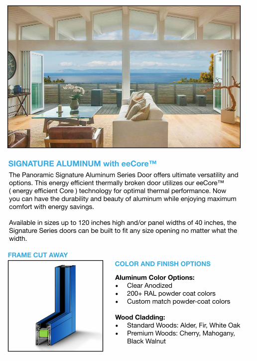
SIGNATURE ALUMINUM with eeCore™The Panoramic Signature Aluminum Series Door offers ultimate versatility and options. This energy efficient thermally broken door utilizes our eeCore™ ( energy efficient Core ) technology for optimal thermal performance. Now you can have the durability and beauty of aluminum while enjoying maximum comfort with energy savings.
Available in sizes up to 120 inches high and/or panel widths of 40 inches, the Signature Series doors can be built to fit any size opening no matter what the width.
Aluminum Color Options: • Clear Anodized• 200+ RAL powder coat colors• Custom match powder-coat colors
Wood Cladding: • Standard Woods: Alder, Fir, White Oak• Premium Woods: Cherry, Mahogany,
Black Walnut

MULTI-POINT LOCKING
All of our Panoramic Door Systems come standard with a multi-point locking system on each access door. The sliding panels integrate with the access door to provide security.
HARDWARE OPTIONS
London Oil Rubbed Bronze
London Brushed Nickel
SheffieldSatin Nickel
MiamiWhite
New York Oil Rubbed Bronze
New York Brushed Nickel
SheffieldBronze
TRACK DETAILSFlush Track
Offers best water barrier. Recommended for most applications.
Lowest threshold. Caution: Minimal protection against water infiltration.
Up-stand Track

Aluminum‐Clad Patio Doors 1
SECTION 085213 ALUMINUM-CLAD PATIO DOORS
PART 1 GENERAL 1.1 SECTION INCLUDES
A. Wood Patio Doors: In-swing patio doors.
1.2 REFERENCES
A. Window and Door Manufacturers Association (WDMA):
1. AAMA/WDMA/CSA 101/I.S.2/A440 North American Fenestration Standard / Specification for windows, doors, and skylights (NAFS)
2. WDMA I.S.4; Water Repellent Preservative Non-Pressure treatment for Millwork B. ASTM International (ASTM):
1. ASTM E 1886 - Standard Test Method for Performance of Exterior Windows, Curtain Walls, Doors, and Impact Protective Systems Impacted by Missile(s) and Exposed to Cyclic Pressure Differentials.
2. ASTM E 1996 - Standard Specification for Performance of Exterior Windows, Curtain Walls, Doors and Impact Protective Systems Impacted by Windborne Debris in Hurricanes.
C. National Fenestration Rating Council (NFRC):
1. NFRC 100 - Procedure for Determining Fenestration Thermal Properties. 2. NFRC 200 - Solar Heat Gain Coefficient and Visible Transmittance.
D. South Florida Building Code Impact Test Procedures (Miami‐Dade TAS):
1. TAS 201 - Impact Test Procedures. 2. TAS 202 - Criteria for testing Impact and Non-Impact Resistant Building Envelope
Components using Uniform Static Air Pressure. 3. TAS 203 - Criteria for testing Products Subject to Cyclic Wind Pressure Loading.
1.3 SUBMITTALS
A. Submit under provisions of Section 00 13 00 Administrative Requirements.
B. Product Data: Manufacturer's data sheets on each product to be used, including:
1. Preparation instructions and recommendations. 2. Storage and handling requirements and recommendations. 3. Installation methods.
C. Shop Drawings: Submit shop drawings indicating details of construction, flashings and relationship with adjacent construction.
D. Selection Samples: For each factory-finished product specified, two complete sets of color chips representing manufacturer's full range of available finishes.
E. Verification Samples: For each factory-finished product specified, two samples, minimum size 6 inches (150 mm) square, representing actual finishes.
F. Quality Assurance Submittals:
1. Design Data, Test Reports: Provide manufacturer test reports indicating product compliance with indicated requirements.
2. WDMA Hallmark certification. G. Closeout Submittals: Refer to Section 01 70 00 Execution and Closeout Requirements
Closeout Submittals.
1.4 QUALITY ASSURANCE

Aluminum‐Clad Patio Doors 2
A. Installer Qualifications: Minimum __ years installing similar assemblies.
B. Certifications: WDMA Hallmark certification label indicating assemblies meet the design requirements.
C. Mock-Up: Provide a mock-up for evaluation of installation techniques and workmanship.
1. Mock-ups shall incorporate surrounding construction, including wall assembly fasteners, flashing, and other related accessories installed in accordance with manufacturer’s approved installation methods.
2. Do not proceed with remaining work until workmanship is approved by Architect. 3. Modify mock-up as required to produce acceptable work. 4. At Substantial Completion, approved mockups may become part of completed Work. 5. Demolish mockups and remove from site.
D. Pre-installation Meeting: Conduct pre-installation meeting on-site two weeks prior to commencement of installation.
1.5 DELIVERY, STORAGE, AND HANDLING
A. Deliver, store and handle materials and products in strict compliance with manufacturer's instructions and recommendations and industry standards.
B. Deliver and store assembly materials and components in manufacturer’s original, unopened, undamaged containers with identification labels intact. Protect from damage.
1.6 PROJECT CONDITIONS
A. Maintain environmental conditions (temperature, humidity, and ventilation) within limits recommended by manufacturer for optimum results. Do not install products under environmental conditions outside manufacturer's recommended limits.
1.7 WARRANTY
A. Manufacturer’s Standard Warranty: Assemblies will be free from defects in materials and workmanship from the date of manufacture for the time periods indicated below:
1. Patio Door Units: 20 years. 2. Clad Finishes: 20 years against peeling, checking, cracking caulk or color change. 3. Pine Wood Products: 20 years against wood decay and termites. 4. Glazing:
a. Insulated Glass: 20 years against seal breakage. b. Laminated Glass: 5 years against delamination. c. Hurricane Glass: 5 years against delamination. d. Specialty Glazing: 5 years.
PART 2 PRODUCTS 2.1 MANUFACTURERS
A. Acceptable Manufacturer: JELD-WEN, Inc.; 2645 Silver Crescent Drive, Charlotte, NC 28273; Toll Free Tel: (800) 535-3936. Tel: (541) 850-2606. Fax: (541) 851-4333. Email: [email protected]. Web: http://www.jeld-wen.com.
2.2 ALUMINUM-CLAD PATIO DOORS - GENERAL
A. Installation Accessories:
1. Flashing: Refer to Section 07600 - Flashing and Sheet Metal. 2. Sealants: OSI Sealants by Henkel Corporation. 3. Sealants: Refer to Section 07920 - Joint Sealants. 4. Sealants: Manufacturer recommended sealants maintain watertight conditions.
B. Materials:
1. Exterior Wood: a. Material: AuraLast Pine.
2. Interior Wood:

Aluminum‐Clad Patio Doors 3
a. Material: AuraLast Pine. C. Interior Finishes for Patio Doors:
1. Color: Primed. D. Exterior Finishes for Patio Doors:
1. AAMA 2605 PVDF Colors a. Color: Brilliant White.
2.3 ALUMINUM-CLAD PATIO DOOR ASSEMBLIES
A. Basis of Design: Custom EPIC Series patio door assemblies as manufactured by JELD-WEN, Inc.
1. Patio Door Type: In-swing patio doors, wood construction. B. Patio Door Fabrication:
1. Frame: Top and bottom rails are solid pine veneer laminated to kiln dried edge-and-end-glued core. Stiles are same veneer laminated to Timberstrand core.
2. Glass: Mounted using silicone glazing compound. a. Glazing Bead: Traditional Beveled.
C. Frames:
1. Material: Select kiln-dried pine AuraLast treated wood. 2. Jamb Width: 4-9/16 inches (116 mm). 3. Cladding: 0.050 inch (1.27 mm) extruded aluminum.
D. Swinging Door Panels:
1. Material: Select kiln-dried pine AuraLast treated wood and Timberstrand engineered wood substrate.
2. Cladding: 0.050 inch (1.27 mm) extruded aluminum. 3. Thickness: 1-23/32 inch (43.7 mm). 4. Layout: 6-5/8 inch (168.3 mm) top rail and stiles, 5. Stiles: Narrow: 4-5/8 inch (117.8 mm). 6. Bottom Rail: 11 inch (279.4 mm).
E. Exterior Trim:
1. Casing: Aluminum Brickmould, 1-3/8 inches (34.9 mm). F. Extension Jambs: Factory applied on three sides of frame interior, in wall depths up to 6-
9/16 inch (166.7 mm).
G. Weatherstripping: Continuous dual foam filled bulb seal compressed between exterior of panel and three sides of frame. Manufacturer’s standard two-piece adjustable astragal on double door units.
H. Sills: 1/2 inch (12.7 mm) high, ADA accessible, dark bronze anodized aluminum with kick plate and integral door sweep at panel (Standard).
I. Hardware:
1. Swinging Doors a. Hinges:
1) Hinges: Ball Bearing Hinge. 2) Hinge Color: Satin Nickel.
b. Locks: No Lock. c. Handle Sets:
1) Handle Sets: [Von Duprin 996L Rhodes w/Escutch & Lock. 2) Handle Set Color: Satin.
d. Exit Device: 1) Exit Device: None.

Aluminum‐Clad Patio Doors 4
e. Closer Option: 1) Closer Option: None.
f. Kickplate 1) Kickplate: None.
J. Glazing for Patio Doors:
1. Strength: Tempered glass. 2. Glazing Type: Tempered Glass.
a. Description: Two panes of glass utilizing continuous roll formed stainless steel spacer and dual seal sealants.
b. Overall Nominal Thickness: 3/4 inch (19 mm). c. Glass Coating: Low E EC 366. d. Glass Protection: Plastic preserve film on interior and exterior of glass. e. Air Space: Air-filled airspace with capillary tubes.
K. Exterior Sliding Insect Screens: None.
PART 3 EXECUTION 3.1 EXAMINATION AND PREPARATION
A. Inspect and prepare openings and substrates using the methods recommended by the manufacturer for achieving best result for the substrates under project conditions.
1. Inspect assembly components prior to installation. 2. Verify rough opening conditions are within recommended tolerances. 3. Form sheet metal sill pan in accordance with manufacturer’s recommendations. 4. Prepare assembly components for installation in accordance with manufacturer’s
recommendations. B. Do not proceed with installation until openings and substrates have been prepared using the
methods recommended by the manufacturer and deviations from manufacturer’s recommended tolerances are corrected. Commencement of installation constitutes acceptance of conditions.
C. If preparation is the responsibility of another installer, notify Architect in writing of deviations from manufacturer’s recommended installation tolerances and conditions.
3.2 INSTALLATION
A. Install assemblies in accordance with manufacturer’s installation guidelines and recommendations including the following.
B. Installation of Patio Doors with Exterior Trim: Insert patio doors into rough opening.
1. Shim side jambs straight. 2. Inspect patio door for square, level and plumb. 3. Fasten patio door through exterior trim around entire patio door. 4. Test and adjust for smooth operation of patio door. 5. Set all nails below wood surface. 6. Structurally secure head and side jambs through shims with mechanical fasteners. 7. Structurally secure sill with mechanical fasteners. 8. Apply flashing to sill, jambs and header. 9. Apply sealant to upper corners and at sill. 10. Install backer rod and sealant at rough opening and door jamb gap. 11. Ensure seal between sill pan and inside face of patio door sill. 12. Install lock set hardware per manufacturer’s instructions.
C. Installation of Patio Doors without Exterior Trim: Insert patio doors into rough opening.
1. Shim side jambs straight. 2. Inspect patio door for square, level and plumb. 3. Fasten patio door through jamb, shim and into rough opening jamb. 4. Test and adjust for smooth operation of patio door. 5. Structurally secure head and side jambs through shims with mechanical fasteners.

Aluminum‐Clad Patio Doors 5
6. Structurally secure sill with mechanical fasteners. 7. Install backer rod and sealant at exterior jambs and head. 8. Seal interior joints between rough opening and jambs with backer rod and sealant. 9. Ensure seal between sill pan and inside face of patio door sill. 10. Install lock set hardware per manufacturer’s instructions.
3.3 FIELD QUALITY CONTROL
A. Manufacturers’ Field Services: Field inspections.
3.4 CLEANING AND PROTECTION
A. Clean the exterior surface and glass with mild soap and water.
B. Protect installed patio doors from damage.
C. Remove and dispose of protective film from glass; touch-up, repair or replace damaged components and assemblies before Substantial Completion.
END OF SECTION

Fra
me
S
ize
Rou
gh O
pen
in
g
Pa
ne
l S
ize
3/4"
Da
yligh
t S
ize
4 5/8"
3/4"
6 5/8"
1 3/4"
5 13/16"
5 3/4"
1 3/16" 4 9/16"S
cre
en
F
ram
e S
ize
15/16"
Scre
en S
ize
11/16"
13/16"
9/16"
Scale: NTS
15
OPERATING 4 9/16" JAMB w/ SWINGING SCREEN - VERTICAL SECTION
Product specifications may change without notice.
Questions? Consult JELD-WEN customer service.
CUSTOM WOOD
CLAD-WOOD PATIO DOOR
INSWING PATIO DOOR
Architectural Design Manual
March 2018

5 3/4"
3/8"
Active Panel Size
Daylight
Opening
4 5/8"
3/4"
4 5/8"
1 3/16"
4 9/16"
9/16"
Screen Frame Size15/16"
Screen Size
Inactive
Panel Size
1 5/16"
Frame Size
Rough Opening
Scale: 3" = 1'-0"
25
FRENCH 4 9/16" JAMB w/ SWINGING SCREEN - HORIZONTAL SECTION
Product specifications may change without notice.
Questions? Consult JELD-WEN customer service.
CUSTOM WOOD
CLAD-WOOD PATIO DOOR
INSWING PATIO DOOR
Architectural Design Manual
March 2018

Aluminum‐Clad Wood Casement Windows
SECTION 08 52 13.10 ALUMINUM-CLAD-WOOD CASEMENT WINDOWS
PART 1 GENERAL 1.1 SECTION INCLUDES
A. Aluminum-Clad-Wood Casement windows.
1.2 REFERENCES
A. Window and Door Manufacturers Association (WDMA):
1. AAMA/WDMA/CSA 101/I.S.2/A440 – North American Fenestration Standard/Specification for windows, doors, and skylights (NAFS)
2. WDMA I.S.4; Water Repellent Preservative Non-Pressure treatment for Millwork B. National Fenestration Rating Council (NFRC):
1. NFRC 100 - Procedure for Determining Fenestration Product U-Factors. 2. NFRC 200 – Procedure for Determining Fenestration Product Solar Heat Gain
Coefficient and Visible Transmittance at Normal Incidence. 1.3 SUBMITTALS
A. Submit under provisions of Section 0 13 00 – Administrative Requirements.
B. Product Data: Manufacturer's data sheets on each product to be used, including:
1. Preparation instructions and recommendations. 2. Storage and handling requirements and recommendations. 3. Installation methods.
C. Shop Drawings: Submit shop drawings indicating details of construction, flashings and relationship with adjacent construction.
D. Selection Samples: For each factory-finished product specified, two complete sets of color chips representing manufacturer's full range of available finishes.
E. Verification Samples: For each factory-finished product specified, two samples, minimum size 6 inches (150 mm) square, representing actual finishes.
F. Design Data, Test Reports: Provide manufacturer test reports indicating product compliance with indicated requirements.
G. Closeout Submittals: Refer to Section 0 17 00 Execution and Closeout Requirements Closeout Submittals.
1.4 QUALITY ASSURANCE
A. Installer Qualifications: Minimum 2 years installing similar assemblies.
B. Mock-Up: Provide a mock-up for evaluation of installation techniques and workmanship.
1. Mock-ups shall incorporate surrounding construction, including wall assembly fasteners, flashing, and other related accessories installed in accordance with manufacturer's approved installation methods.
2. Do not proceed with remaining work until workmanship is approved by Architect. 3. Modify mock-up as required to produce acceptable work. 4. At Substantial Completion, approved mockups may become part of completed work. 5. Demolish mockups and remove from site.
C. Pre-installation Meeting: Conduct pre-installation meeting on-site two weeks prior to commencement of installation.
1.5 DELIVERY, STORAGE, AND HANDLING

Aluminum‐Clad Wood Casement Windows
A. Deliver, store and handle materials and products in strict compliance with manufacturer's instructions and recommendations and industry standards.
B. Deliver and store assembly materials and components in manufacturer's original, unopened, undamaged containers with identification labels intact. Protect from damage.
1.6 PROJECT CONDITIONS
A. Maintain environmental conditions (temperature, humidity, and ventilation) within limits recommended by Manufacturer for optimum results. Do not install products under environmental conditions outside manufacturer's recommended limits.
1.7 WARRANTY
A. Manufacturer's Standard Warranty: Assemblies will be free from defects in materials and workmanship from the date of manufacture for the time periods indicated below:
1. Patio Door Units: 20 years. 2. Window Units: 20 years. 3. Clad Finishes: 10 years against peeling, checking, cracking caulk or color change. 4. AAMA 2605 Clad Finishes: 20 years against peeling, checking, cracking or color
change. 5. Glazing:
a. Insulated Glass: 20 years against seal breakage. b. Laminated Glass: 5 years against delamination. c. Specialty Glazing: 5 years.
PART 2 PRODUCTS 2.1 MANUFACTURERS
A. Acceptable Manufacturer: JELD-WEN, Inc.; 2645 Silver Crescent Drive, Charlotte, NC 28273; Toll Free Tel: 800-535-3936; Tel: 541-850-2606; Fax: 541-851-4333; Email: mailto:[email protected]; Web: http://www.jeld-wen.com.
2.2 ALUMINUM-CLAD WOOD WINDOWS - GENERAL
A. Installation Accessories:
1. Flashing: Refer to Section 07600 - Flashing and Sheet Metal. 2. Sealants: OSI Sealants by Henkel Corporation. 3. Sealants: Refer to Section 07920 - Joint Sealants. 4. Sealants: Manufacturer recommended sealants to maintain watertight conditions.
B. Materials:
1. Exterior Cladding: Extruded aluminum. 2. Interior Wood:
a. Material: AuraLast Pine. C. Finishes:
1. Interior Finishes for Windows: a. Finish: Primed.
2. Exterior Finishes for Windows: a. Standard Color:
1) Color: Brilliant White.
2.3 ALUMINUM-CLAD-WOOD WINDOW ASSEMBLIES (SITELINE)
A. Basis of Design: Siteline Series aluminum-clad-wood windows assemblies as manufactured by JELD-WEN, Inc.
1. Window Type: Casement windows.

Aluminum‐Clad Wood Casement Windows
B. Window Fabrication:
1. Window Type: Casement windows. a. Frame: Head corner joints mechanically fastened over silicone injected nylon
corner key. Sill corner joints sealed with foam gasket and screw boss construction.
b. Sash: Corner joints slot-and-tenoned, and mechanically fastened. c. Glass: Mounted using silicone glazing compound and secured with interior
applied profiled wood stops. 1) Glazing Bead: [Traditional Beveled] [Contemporary Square].
C. Frames:
1. Material: Select kiln-dried pine AuraLast treated wood. 2. Casement, Awning and Picture Windows Base Frame: 3-3/16 inch (81 mm). 3. Double-Hung Windows Base Frame: 4-9/16 inches (115 mm) 4. Horizontal Sliding Windows Base Frame: 4-9/16 inches (115 mm) 5. Jamb Width: 4-9/16 inches (116 mm). 6. Cladding: 0.050 inch (1.27 mm) extruded aluminum.
D. Sashes: Select kiln-dried pine AuraLast treated wood.
1. Sash Thickness: 1-7/16 inches (36.5 mm) 2. Cladding: 0.045 inch (1.2 mm) extruded aluminum.
E. Exterior Trim: Nailing Fin.
1. Sill Nosing: Standard. F. In-Sash Interior Radius Trim:
1. Material: [Pine] [Oak]. 2. Pattern: As scheduled and indicated on Drawings. 3. Casing: As scheduled and indicated on Drawings.
G. Factory Applied Extension Jambs:
1. Configuration: On 3 sides of frame interior in preparation for stool by others. H. Weatherstripping:
1. Casement Windows: Flexible hinged leaf applied to sash and foam filled bulb at full perimeter of frame.
I. Window Hardware:
1. Casement Windows: a. Hinges: Standard hinge. b. Operator: Single arm roto type. c. Handle: Nesting Crank handle. d. Finish: White.
J. Glazing for Windows:
1. Strength: Annealed glass. 2. Glazing Type: Insulated glass.
a. Description: Two panes of glass utilizing continuous roll formed stainless steel spacer and dual seal sealants.
b. Overall Nominal Thickness: 3/4 inch (19 mm). c. Glass Coating: Low-E EC 366. d. Glass Protection: Plastic preserve film on interior and exterior of glass. e. Air Space: Air-filled airspace with capillary tubes.
K. Interior Insect Screens:
1. Material: Charcoal fiberglass screen cloth (18 by 16 mesh) set in painted roll formed aluminum frame. a. Finish: White.

Aluminum‐Clad Wood Casement Windows
PART 3 EXECUTION 3.1 EXAMINATION AND PREPARATION
A. Inspect and prepare openings and substrates using the methods recommended by the manufacturer for achieving best result for the substrates under project conditions.
1. Inspect assembly components prior to installation. 2. Verify rough opening conditions are within recommended tolerances. 3. Form sheet metal sill pan in accordance with manufacturer's recommendations. 4. Prepare assembly components for installation in accordance with manufacturer's
recommendations. B. Do not proceed with installation until openings and substrates have been prepared using the
methods recommended by the manufacturer and deviations from manufacturer's recommended tolerances are corrected. Commencement of installation constitutes acceptance of conditions.
C. If preparation is the responsibility of another installer, notify Architect in writing of deviations from manufacturer's recommended installation tolerances and conditions.
3.2 INSTALLATION
A. Install assemblies in accordance with manufacturer's installation guidelines and recommendations including the following.
B. Installation of Windows With Nailing Fins: Insert windows into rough opening.
1. Shim side jambs straight. 2. Inspect window for square, level and plumb. 3. Fasten window through nailing fins around entire window. 4. Test and adjust for smooth operation of window. 5. Set all nails below wood surface.
C. Installation of Patio Doors With Nailing Fins: Insert patio doors into rough opening.
1. Shim side jambs straight. 2. Inspect patio door for square, level and plumb. 3. Fasten patio door through nailing fins around entire patio door. 4. Test and adjust for smooth operation of patio door.
3.3 FIELD QUALITY CONTROL
A. Manufacturers' Field Services: Perform field inspections as recommended by manufacturer.
3.4 CLEANING AND PROTECTION
A. Clean the exterior surface and glass with mild soap and water.
B. Protect installed windows from damage.
C. Remove and dispose of protective film from glass; touch-up, repair or replace damaged components and assemblies before Substantial Completion.
END OF SECTION

Fra
me
S
ize
Rou
gh O
pen
in
g
3/8"
1 1/8"
1 1/8"
Sa
sh
S
ize
4 9/16"1 1/4"
5 13/16"
4 9/16"1 1/4"
5 13/16"
15/16"
15/16"
Scre
en S
ize
1 5/8"
2 9/16"
5/8"
3 3/16"
3 3/16"
5/8"
3/8"
Scale: 6" = 1' - 0"
16
OPERATING - VERTICAL SECTION
Architectural Design Manual
February 2018
Product specifications may change without notice.
Questions? Consult JELD-WEN customer service.
SITELINE WOOD
CLAD-WOOD WINDOW
CASEMENT

4 9/16"
Daylight
Opening
1 1/4"
5 13/16"
Sash Size
2 1/16"2 1/16"
Frame Size
Rough Opening
3/8"3/8"
1 5/8"
1 1/8"
3 3/16"
5/8"
4 9/16"
1 1/4"
5 13/16"
3 3/16"
5/8"
1 1/8"
1 5/8"
Scale: 6" = 1' - 0"
17
OPERATING - HORIZONTAL SECTION
Architectural Design Manual
February 2018
Product specifications may change without notice.
Questions? Consult JELD-WEN customer service.
SITELINE WOOD
CLAD-WOOD WINDOW
CASEMENT

Da
yligh
t O
pe
nin
g
2 1/16"
2 1/16"
Sash
S
ize
4 9/16"1 1/4"
15/16"
3 3/16"
Fra
me
S
ize
Rou
gh O
pe
ning
1 1/8"
1 1/8"
4 9/16"1 1/4"
5 13/16"
5/8"
3 3/16"
5/8"
5 13/16"
15/16"
3/8"
3/8"
Scale: 6" = 1' - 0"
20
FIXED - VERTICAL SECTION
Architectural Design Manual
February 2018
Product specifications may change without notice.
Questions? Consult JELD-WEN customer service.
SITELINE WOOD
CLAD-WOOD WINDOW
CASEMENT

Frame Size
Rough Opening
Daylight
Opening
2 1/16"2 1/16"
Sash Size
3/8"
15/16"
1 1/8" 1 1/8"
3/8"
15/16"
4 9/16"
1 1/4"
5 13/16"
3 3/16"
4 9/16"
1 1/4"
5 13/16"
3 3/16"
5/8" 5/8"
Scale: 6" = 1' - 0"
21
Architectural Design Manual
February 2018
Product specifications may change without notice.
Questions? Consult JELD-WEN customer service.
SITELINE WOOD
CLAD-WOOD WINDOW
CASEMENT
FIXED - HORIZONTAL SECTION

This photo sample is intended to represent general color range and texture. Precise color fidelity is difficult to obtain in print. Brick selection should be made from product samples.
AUTUMN LEAF GRAINDenver, Coloradowww.GeneralShale.com
BR-PSS 0004-0313
