scope of work (electrical)cidco.maharashtra.etenders.in/tnduploads/cidco/tndheader/tnd...scope of...
TRANSCRIPT

CIDCO OF MAHARASHTRA LTD C.A.No.03/CIDCO/EE(Elect)/2011-12 Sr. Page No.
SCOPE OF WORK (ELECTRICAL)
GENERAL
The Scope of work consists of :-
1.0 Planning, designing & execution of HT/LT Cable network as per direction
of Engineer-in-Charge and as per Schedule ‘A’.
2.0 The work includes:-
a) Establishment of Distribution HT/LT network in various sectors.
3.0 Providing & commissioning of :
a) 11KV XLPE cable.
b) L.T. Distribution network consisting of feeder pillars/minipillars
(outdoor type) complete with L.T. underground XLPE armoured
cable network upto consumer’s Electric meter room.
c) All related allied works like trenching, earthing, safety equipments
& obtaining statutory approvals.
NOTE:All the equipments used shall be compatible with SCADA & the
agency has to submit protocol & mapping drawings of equipments
wherever applicable. All protocol shall be as per IEC Standard (e.g.
for relay IEC 870-5-103)
4.0 The entire electrical works should be carried out in accordance with the
specifications without any extra cost. The work shall conform to latest
edition of Indian Standard Specifications & Indian Electricity Rules.
5.0 The works shall be completed as per the requirement of ISO:9002 & all
required documents for the same shall be made available.

CIDCO OF MAHARASHTRA LTD C.A.No.03/CIDCO/EE(Elect)/2011-12 Sr. Page No.
6.0 The Technical specification of all the equipment and the quantities
required of various accessories & auxiliaries. The contractor shall also
ascertain the quantities of items such as HT/LT cables, earthing material,
supporting steel pipes etc. and procure the material as per requirement.
Excess material brought to site & not installed shall not be accepted by
CIDCO nor it will be paid for.
7.0 Inspection:
7.1 All equipment shall be offered for inspection. 7.2 The inspection shall be carried out by CIDCO representative at any stage
of manufacturing. The contractor shall give free access to the inspector at
a reasonable notice.
7.3 The equipment shall be offered for final inspection at least fifteen days in
advance to enable CIDCO to witness the acceptance tests.
7.4 No equipment shall be dispatched to site from the manufacturers work
unless dispatch clearance certificate is issued by the inspecting authority
of CIDCO.
7.5 The contractor shall arrange for the inspection of the equipment by
CIDCO representative & co-ordinate with them for timely dispatches at no
extra cost to CIDCO, including traveling & boarding expenses.
8.0 Documentation : 8.1 The contractor on receipt of LOI shall submit five sets of relevant
descriptive & illustrative literature and general arrangement, schematic
drawings, foundation plans, and any other drawings and the general
technical particulars of all the equipment to be supplied.

CIDCO OF MAHARASHTRA LTD C.A.No.03/CIDCO/EE(Elect)/2011-12 Sr. Page No.
8.2 On completion of the above works, and commissioning, the contractor
shall prepare a set of “as built drawings”, compile all the vendor drawings,
shop test reports, inspection reports, site test reports, operation and
maintenance literature of major equipments for handing over to CIDCO.
This shall be compiled in four sets duly bound in a neat handy book.
Separate comprehensive operation & maintenance manual should also be
submitted in four sets.
9.0 Supervision of Erection :
The contractor shall arrange for a trained supervisor of respective
equipment manufacturer during installation, testing & commissioning who
will direct the sequence of erection, make necessary adjustments/
settings, make the equipment ready for testing, certify the pre-
commissioning checks and give permission for commissioning. This shall
be arranged by the contractor at no extra cost to CIDCO.
10.0 The drawings given in the tender are indicative. The successful agency
will have to make his own assessment before execution of work.
GENERAL TECHNICAL SPECIFICATIONS
1.0 INTRODUCTION :
CIDCO is planning to provide power supply distribution infrastructure in
Kharghar node with Hi-tech equipments for reliable power supply to the
inhabitants of Kharghar node in Sector-25 to 45.
2.0 This specifications given in brief the technical requirements for the
installation, testing & commissioning of power supply distribution
infrastructure at Kharghar node in Sector-25 to 45.
CIDCO OF MAHARASHTRA LTD C.A.No.03/CIDCO/EE(Elect)/2011-12 Sr. Page No.
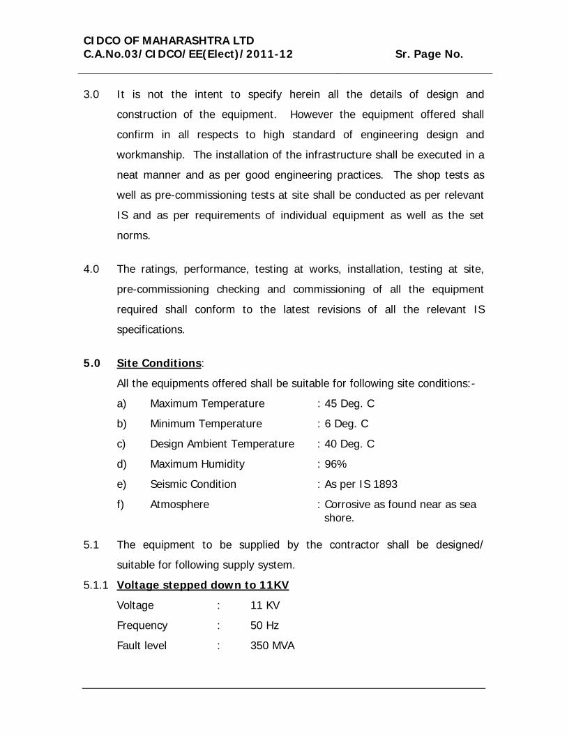
3.0 It is not the intent to specify herein all the details of design and
construction of the equipment. However the equipment offered shall
confirm in all respects to high standard of engineering design and
workmanship. The installation of the infrastructure shall be executed in a
neat manner and as per good engineering practices. The shop tests as
well as pre-commissioning tests at site shall be conducted as per relevant
IS and as per requirements of individual equipment as well as the set
norms.
4.0 The ratings, performance, testing at works, installation, testing at site,
pre-commissioning checking and commissioning of all the equipment
required shall conform to the latest revisions of all the relevant IS
specifications.
5.0 Site Conditions:
All the equipments offered shall be suitable for following site conditions:-
a) Maximum Temperature : 45 Deg. C
b) Minimum Temperature : 6 Deg. C
c) Design Ambient Temperature : 40 Deg. C
d) Maximum Humidity : 96%
e) Seismic Condition : As per IS 1893
f) Atmosphere : Corrosive as found near as sea shore.
5.1 The equipment to be supplied by the contractor shall be designed/
suitable for following supply system.
5.1.1 Voltage stepped down to 11KV
Voltage : 11 KV
Frequency : 50 Hz
Fault level : 350 MVA
CIDCO OF MAHARASHTRA LTD C.A.No.03/CIDCO/EE(Elect)/2011-12 Sr. Page No.
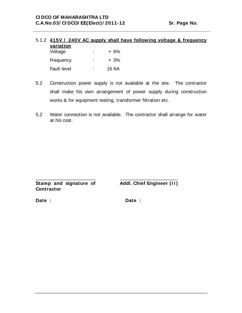
5.1.2 415V / 240V AC supply shall have following voltage & frequency variation Voltage : + 6%
Frequency : + 3%
Fault level : 16 KA
5.2 Construction power supply is not available at the site. The contractor
shall make his own arrangement of power supply during construction
works & for equipment testing, transformer filtration etc.
5.2 Water connection is not available. The contractor shall arrange for water
at his cost. _______________________ ______________________ Stamp and signature of Contractor
Addl. Chief Engineer (II)
Date :
Date :

CIDCO OF MAHARASHTRA LTD C.A.No.03/CIDCO/EE(Elect)/2011-12 Sr. Page No.
I) TECHNICAL SPECIFICATIONS FOR 11KV XLPE CABLE
1.0 SCOPE 1.1 This technical specification covers design, manufacture, testing at
manufacturer’s works, packing & delivery of High Voltage Cross linked
polyethylene insulated PVC Sheathed cables suitable for 11 KV.
1.2 It is not the intent to specify completely herein all the details of design &
construction of the cables. However the cables shall conform to high
standards of engineering, design & workman ship. The equipment offered
shall be complete with all components necessary for its effective and
trouble free operation.
2.0 STANDARDS
2.1 unless otherwise specified elsewhere in its specification, the rating,
performance and testing of cables & accessories shall conform to the
latest revision of all relevant standards.
2.2 A list of such standards is enclosed at ANNEXURE – I.
3.0 PRINCIPAL PARAMETERS
The high Voltage Cables and accessories covered in this specification shall
meet the technical requirements listed at ANNEXURE – II and the
following general technical requirement.

CIDCO OF MAHARASHTRA LTD C.A.No.03/CIDCO/EE(Elect)/2011-12 Sr. Page No.
4.0 GENERAL TECHNICAL REQUIREMENT
4.1 Conductor
4.1.1 The conductor shall be made from electrically pure Aluminium wires. The
wires shall be stranded together and compacted.
4.1.2 The conductor shall be circular in shape.
4.2 Conductor Shielding
An extruded semi conducting compound shall be provided on the
conductor to provide a smooth surface & eliminate electrical stress
concentration.
4.3 Insulation
The core insulation shall be with Cross linked polyethylene unfilled
insulation compound. It shall be free from voids and shall withstand all
mechanical and thermal stresses under steady state & transient operating
conditions. The insulation shall be applied by triple extrusion process.
4.4 Insulation Shielding
The insulation shielding shall consist of non-metallic semi-conducting
compound in combination with non-metallic screening of copper. It shall
be possible to strip the insulation screening without applying heat. The
screen shall be capable to carry single line to ground fault current for a
duration of one second.
4.5 The conductor screen and XLPE insulation screen shall all be extruded in
one operation by extrusion to ensure perfect bonding.
4.6 Armouring
G.I. Flat street wire armouring shall be provided over the inner sheath.
CIDCO OF MAHARASHTRA LTD C.A.No.03/CIDCO/EE(Elect)/2011-12 Sr. Page No.
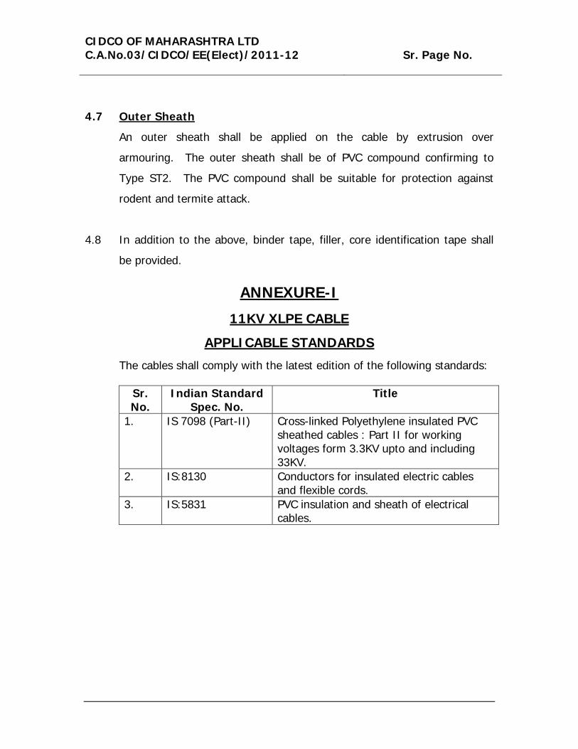
4.7 Outer Sheath
An outer sheath shall be applied on the cable by extrusion over
armouring. The outer sheath shall be of PVC compound confirming to
Type ST2. The PVC compound shall be suitable for protection against
rodent and termite attack.
4.8 In addition to the above, binder tape, filler, core identification tape shall
be provided.
ANNEXURE-I
11KV XLPE CABLE
APPLICABLE STANDARDS
The cables shall comply with the latest edition of the following standards:
Sr. No.
Indian Standard Spec. No.
Title
1. IS 7098 (Part-II) Cross-linked Polyethylene insulated PVC sheathed cables : Part II for working voltages form 3.3KV upto and including 33KV.
2. IS:8130 Conductors for insulated electric cables and flexible cords.
3. IS:5831 PVC insulation and sheath of electrical cables.
CIDCO OF MAHARASHTRA LTD C.A.No.03/CIDCO/EE(Elect)/2011-12 Sr. Page No.
Sr. No.
Indian Standard Spec. No.
Title
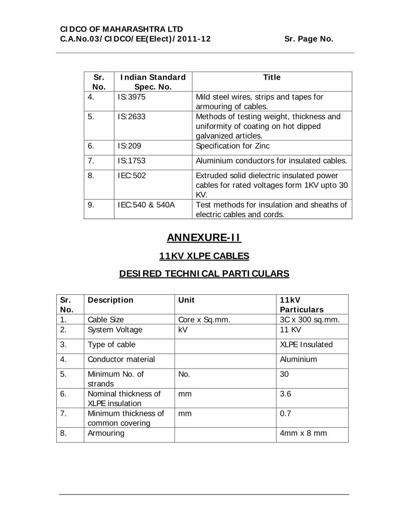
4. IS:3975 Mild steel wires, strips and tapes for armouring of cables.
5. IS:2633 Methods of testing weight, thickness and uniformity of coating on hot dipped galvanized articles.
6. IS:209 Specification for Zinc
7. IS:1753 Aluminium conductors for insulated cables.
8. IEC:502 Extruded solid dielectric insulated power cables for rated voltages form 1KV upto 30 KV.
9. IEC:540 & 540A Test methods for insulation and sheaths of electric cables and cords.
ANNEXURE-II
11KV XLPE CABLES
DESIRED TECHNICAL PARTICULARS
Sr. No.
Description Unit 11kV Particulars
1. Cable Size Core x Sq.mm. 3C x 300 sq.mm. 2. System Voltage kV 11 KV
3. Type of cable XLPE Insulated
4. Conductor material Aluminium
5. Minimum No. of strands
No. 30
6. Nominal thickness of XLPE insulation
mm 3.6
7. Minimum thickness of common covering
mm 0.7
8. Armouring 4mm x 8 mm

CIDCO OF MAHARASHTRA LTD C.A.No.03/CIDCO/EE(Elect)/2011-12 Sr. Page No.
Sr. No.
Description Unit 11kV Particulars
9. Minimum thickness of outer sheath
mm 2.68
10. Approximate overall diameter
mm 81
11. Approximate net weight
kg/km 7260
12. Normal Delivery Length m 250
13. Max. DC Resistance at 20 deg C
Ohms/km 0.1
14. Approximate AC Resistance
Ohms/km 0.13
15. Approximate reactance at 50 Hz.
Ohms/km 0.095
16. Approximate Capacitance per phase
Mfd/km 0.475
17. Current rating Amps 355 (in ground) 440 (in air
18. Short time current rating
kA 28.2
19. Permissible short circuit temperature
Deg.C 250
1.1 Earthing :
1.1.1 Each Board, shall be provided with an earth busbar running along the
entire length of the board. Material and size of the earth busbar shall be
as specified. At either end of the earth bus, one (1) clamp type terminal
with nuts, bolts and earthing conductor shall be provided for bolting
Purchaser’s earthing conductor. In case the earth bus is provided near
top of the Board, one down comer at either end shall be provided for
connection to the Owner’s earthing conductor.
1.1.2 Earth busbars shall be supported at suitable intervals.

CIDCO OF MAHARASHTRA LTD C.A.No.03/CIDCO/EE(Elect)/2011-12 Sr. Page No.
1.1.3 Positive connection between all the frames of equipment mounted in the
switchboard and earth busbar shall be provided by using insulated
copper wires/bare busbars of cross section equal to that of the busbar.
1.1.4 All instrument and relay cases shall be connected to the earth busbar
using 1100/650V grade, 2.5 sq.mm. stranded copper earthing
conductor.
II) SPECIFICATIONS FOR EARTHING INSTALLATION
1.0 SCOPE
The intent of this specification is to define the requirements for the
supply, installation, testing and commissioning of the Earthing System.
Note : The bidder shall have to design the earthing system required for
the installation after measuring the soil resistivity & approvals.
2.0 EARTHING CONDUCTOR/ELECTRODE :
The main grid conductor shall be hot dip galvanized G.I. flat or PVC
insulated aluminium conductor/copper conductor. Sizes for main
conductors shall be marked on the drawings. Earth electrodes shall be as
per IS standard. Thickness of hot dip galvanizing shall not be less than 75
microns.
3.0 EARTHING NETWORK:
3.1 The entire earthing installation shall be done in accordance with the
earthing drawings, specifications and the standard drawings of reference
CIDCO OF MAHARASHTRA LTD C.A.No.03/CIDCO/EE(Elect)/2011-12 Sr. Page No.
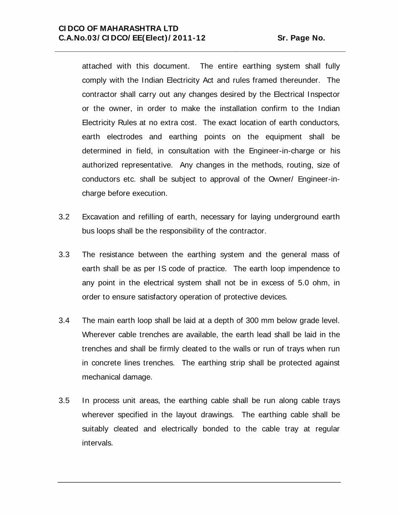
attached with this document. The entire earthing system shall fully
comply with the Indian Electricity Act and rules framed thereunder. The
contractor shall carry out any changes desired by the Electrical Inspector
or the owner, in order to make the installation confirm to the Indian
Electricity Rules at no extra cost. The exact location of earth conductors,
earth electrodes and earthing points on the equipment shall be
determined in field, in consultation with the Engineer-in-charge or his
authorized representative. Any changes in the methods, routing, size of
conductors etc. shall be subject to approval of the Owner/ Engineer-in-
charge before execution.
3.2 Excavation and refilling of earth, necessary for laying underground earth
bus loops shall be the responsibility of the contractor.
3.3 The resistance between the earthing system and the general mass of
earth shall be as per IS code of practice. The earth loop impendence to
any point in the electrical system shall not be in excess of 5.0 ohm, in
order to ensure satisfactory operation of protective devices.
3.4 The main earth loop shall be laid at a depth of 300 mm below grade level.
Wherever cable trenches are available, the earth lead shall be laid in the
trenches and shall be firmly cleated to the walls or run of trays when run
in concrete lines trenches. The earthing strip shall be protected against
mechanical damage.
3.5 In process unit areas, the earthing cable shall be run along cable trays
wherever specified in the layout drawings. The earthing cable shall be
suitably cleated and electrically bonded to the cable tray at regular
intervals.
CIDCO OF MAHARASHTRA LTD C.A.No.03/CIDCO/EE(Elect)/2011-12 Sr. Page No.
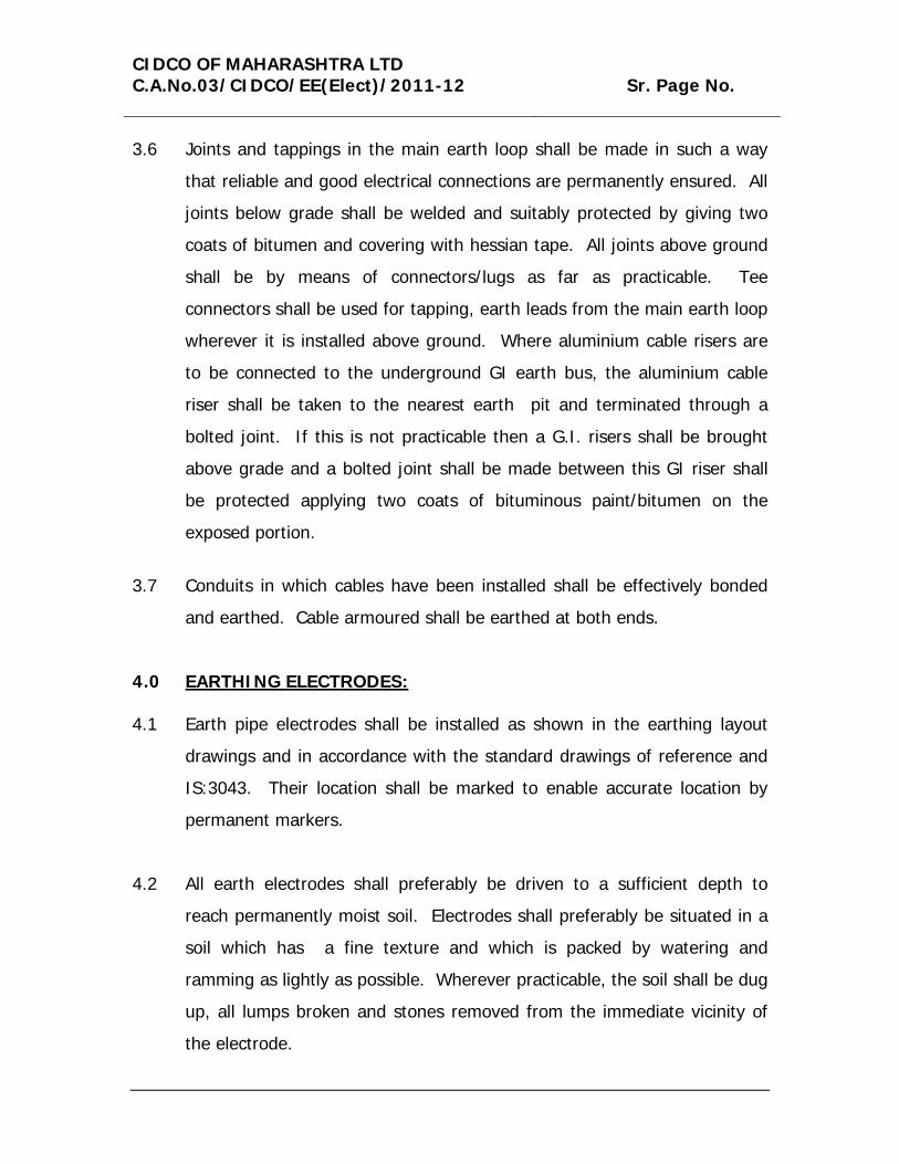
3.6 Joints and tappings in the main earth loop shall be made in such a way
that reliable and good electrical connections are permanently ensured. All
joints below grade shall be welded and suitably protected by giving two
coats of bitumen and covering with hessian tape. All joints above ground
shall be by means of connectors/lugs as far as practicable. Tee
connectors shall be used for tapping, earth leads from the main earth loop
wherever it is installed above ground. Where aluminium cable risers are
to be connected to the underground GI earth bus, the aluminium cable
riser shall be taken to the nearest earth pit and terminated through a
bolted joint. If this is not practicable then a G.I. risers shall be brought
above grade and a bolted joint shall be made between this GI riser shall
be protected applying two coats of bituminous paint/bitumen on the
exposed portion.
3.7 Conduits in which cables have been installed shall be effectively bonded
and earthed. Cable armoured shall be earthed at both ends.
4.0 EARTHING ELECTRODES:
4.1 Earth pipe electrodes shall be installed as shown in the earthing layout
drawings and in accordance with the standard drawings of reference and
IS:3043. Their location shall be marked to enable accurate location by
permanent markers.
4.2 All earth electrodes shall preferably be driven to a sufficient depth to
reach permanently moist soil. Electrodes shall preferably be situated in a
soil which has a fine texture and which is packed by watering and
ramming as lightly as possible. Wherever practicable, the soil shall be dug
up, all lumps broken and stones removed from the immediate vicinity of
the electrode.
CIDCO OF MAHARASHTRA LTD C.A.No.03/CIDCO/EE(Elect)/2011-12 Sr. Page No.
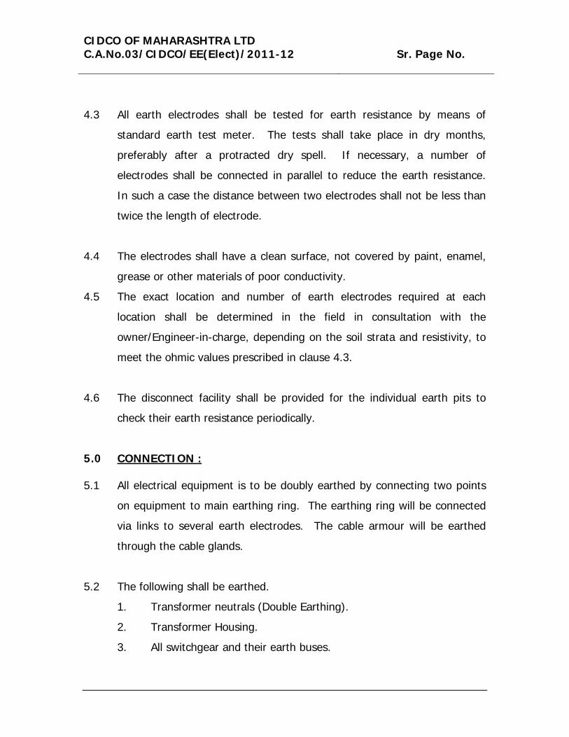
4.3 All earth electrodes shall be tested for earth resistance by means of
standard earth test meter. The tests shall take place in dry months,
preferably after a protracted dry spell. If necessary, a number of
electrodes shall be connected in parallel to reduce the earth resistance.
In such a case the distance between two electrodes shall not be less than
twice the length of electrode.
4.4 The electrodes shall have a clean surface, not covered by paint, enamel,
grease or other materials of poor conductivity.
4.5 The exact location and number of earth electrodes required at each
location shall be determined in the field in consultation with the
owner/Engineer-in-charge, depending on the soil strata and resistivity, to
meet the ohmic values prescribed in clause 4.3.
4.6 The disconnect facility shall be provided for the individual earth pits to
check their earth resistance periodically.
5.0 CONNECTION :
5.1 All electrical equipment is to be doubly earthed by connecting two points
on equipment to main earthing ring. The earthing ring will be connected
via links to several earth electrodes. The cable armour will be earthed
through the cable glands.
5.2 The following shall be earthed.
1. Transformer neutrals (Double Earthing).
2. Transformer Housing.
3. All switchgear and their earth buses.

CIDCO OF MAHARASHTRA LTD C.A.No.03/CIDCO/EE(Elect)/2011-12 Sr. Page No.
4. Motor Frames.
5. Non-current carrying metallic parts of electrical equipment such as
switchgear, switch rocks, panel boards, motor control centers,
lighting, power and instrument panels, push button stations, cable
trays, pipes conduits, terminal boxes etc.
6. All fences/enclosures housing electrical equipment.
7. All still structures, rails etc. including bonding between sections.
8. Shield Wire.
9. Structural steel Columns of building etc.
10. Loading racks.
5.3 System shall be earthed by two distint conductors directly connected to
independent earth electrodes which in turn, shall be connected to the
earth loop. The earth connection shall be properly made. A small flexible
aluminium cable loops to bridge the top cover of the transformer and the
tank shall be provided to avoid earth fault current passing through
fastening bolts when there is lightning surge, high voltage surge or failure
of the bushings.
5.4 Each Lightening Arrestor shall be connected to a separate electrode
located as close as possible to it and within he fenced area for each set of
arrestors shall be spaced such that they are all within the enclosing fence.
Each of these electrodes shall be connected to the main earth grid.
5.5 The shield wire shall be connected with the main grid solidly and net
through supporting steel structures.
5.6 All paint, scale and enamel shall be removed from the contact surface
before the earthing connections are made.

CIDCO OF MAHARASHTRA LTD C.A.No.03/CIDCO/EE(Elect)/2011-12 Sr. Page No.
5.7 All hardware used for earthing installation shall be hot dip galvanized for
zinc passivated. Spring washers shall be used for all earthing connections
of equipment having moving parts and for all the connections subject to
vibrations etc.
5.8 Lighting fixtures shall be earthes through the extra core provided in the
lighting cable this purpose.
6.0 TESTING
Earthing system/connections shall be tested as follows:
6.1 Resistance of individual electrodes shall be measured after disconnecting
it from the grid.
6.2 Earthing resistance of the grid shall be measured after connecting all the
electrodes to the grid and generally the test value shall conform to
IS:3043 code of practice unless otherwise specified.
6.3 The resistance to earth shall be measured at the following:
a) At each electrical system earth or system at the following.
b) At each earth provided for structure lightning protections.
c) At one point on each earthing system used to earth electrical
equipment enclosures.
d) At one point on each earthing system used to earth wiring system
enclosures such as metal conduits and cable sheaths or armour.
e) At one point on each fence enclosing electrical equipment.

CIDCO OF MAHARASHTRA LTD C.A.No.03/CIDCO/EE(Elect)/2011-12 Sr. Page No.
Measurement shall be made before connection is made between
the ground and the object to be grounded.
IV) TECHNICAL SPECIFICATIONS FOR L.T. XLPE POWER CABLE
1.0 GENERAL
The cables shall be suitable for laying in racks, ducts, trenched, conduits
and underground buried installation with uncontrolled back fill and
chances of flooding by water.
They shall be designed to withstand all mechanical electrical and thermal
stresses under steady state and transient operating conditions. The XLPE
cables shall withstand without damage a three-phase fault current of at
least 26.2 kA for at least 0.5 second. The armour for these power cables
shall be capable of carrying 26.2 kA for at least 0.5 second without
exceeding the maximum allowable temperature of outer sheath.
The XLPE insulated cables shall be capable of withstanding a conductor
temperature of 250 degree C during a short circuit without any damage.
The aluminium wires unsed for manufacturing the cables shall be true
circular in shape before stranding and shall be uniformly good quality, free
from defects. All aluminium used in the cables shall be of H2 grade.
The fillers and inner sheath shall be of non- hygroscopic, fire retardant
material, shall be softer then insulation and outer sheath shall be suitable
for the operating temperatures of the cable.
Progressive sequential marking of the length of cable in meters at every
one meter shall be provided on the outer sheath of all cables.

CIDCO OF MAHARASHTRA LTD C.A.No.03/CIDCO/EE(Elect)/2011-12 Sr. Page No.
The cable shall have outer sheath of a material with an oxygen index of
not less than 29 and a temperature index of not less than 250 degree C.
All the cables shall pass fire resistance test as per IS:1554 (part-1)
Repaired cables shall not be accepted.
Allowable tolerance on the overall diameter of the cables shall be plus or
minus 2 mm.
2.0 XLPE POWER CABLES
The XLPE insulated cables shall be of FR type, C1 category conforming to
IS:7098 (part-1) and its amendments read along with this specification.
The conductor shall be stranded aluminium circular/sector shaped and
compacted. In multicore cables, the core shall be identified by red,
yellow, blue and black coloured strips or colouring of insulation. A distinct
inner sheath shall be provided in all multicore cables. For XLPE cables,
the inner sheath shall be of extruded PVC to type ST-2 of IS:5831. When
armouring is specified for single core cables, the same shall consist of
aluminium wires/strips. The outer sheath shall be extruded PVC to Type
ST-2 of IS:5831 for all XLPE cables.
3.0 CABLE DRUMS :
Cable shall be supplied non-returnable wooden or steel drums of heavy
construction. Wooden drum shall be properly seasoned, sound and free
from defects. Wood preservative shall be applied to the entire drum.
Standard lengths for each size of power and control cables shall be
500/1000 metres (LT cables). The cable length per drum shall be subject
to a tolerance of plus or minus 5% of the standard drum length. The
owner shall have the option of rejecting cable drums with shorter lengths.
However, the total quantity of cables after taking into consideration of all

CIDCO OF MAHARASHTRA LTD C.A.No.03/CIDCO/EE(Elect)/2011-12 Sr. Page No.
cable drums for each size shall be within the tolerance of plus or minus
2%.
A layer of water proof paper shall be applied to the surface of the drums
and over the outermost cable layer.
A clear space of at least 40 mm shall be left between the cables and the
lagging.
Each drum shall carry the manufacturer’s name, the purchaser’s name,
address and contact number and type, size and length of the cable, net
and gross weight stenciled on the both sides of drum. A tag containing
the same information shall be attached to the leading end of the cable.
An arrow and suitable accompanying wording shall be marked on one end
of the reel indicating the direction in which is should be rolled.
Packing shall be sturdy and adequate to protect the cables, from any
injury due to mishandling or other conditions encountered during
transportation, handling and storage. Both cable ends shall be sealed
with PVC/Rubber caps so as to eliminate ingress of water during
transportation and erection.
4.0 TESTS
All cables shall conform to all type, routine and acceptance tests listed in
the relevant IS.
All power cables shall meet the requirements of the following additional
test and type test may be conducted to prove their capabilities.
1. Short time current test of conductors.
2. Short time current test on armours.
CIDCO OF MAHARASHTRA LTD C.A.No.03/CIDCO/EE(Elect)/2011-12 Sr. Page No.
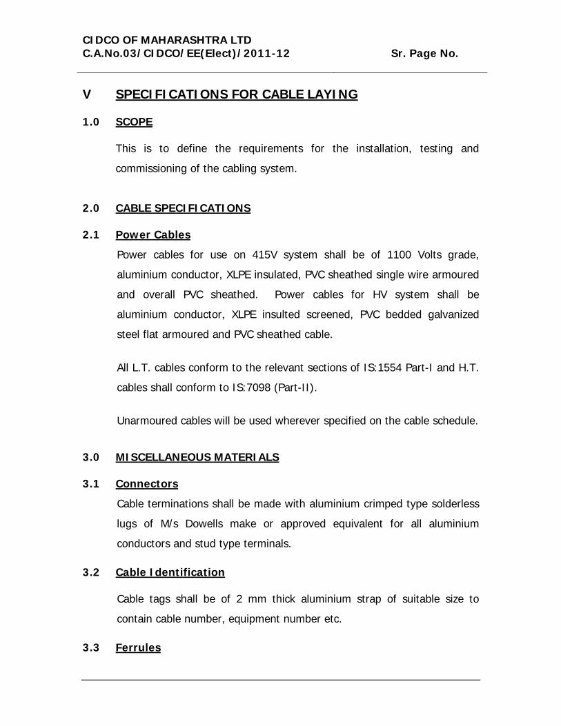
V SPECIFICATIONS FOR CABLE LAYING
1.0 SCOPE
This is to define the requirements for the installation, testing and
commissioning of the cabling system.
2.0 CABLE SPECIFICATIONS
2.1 Power Cables
Power cables for use on 415V system shall be of 1100 Volts grade,
aluminium conductor, XLPE insulated, PVC sheathed single wire armoured
and overall PVC sheathed. Power cables for HV system shall be
aluminium conductor, XLPE insulted screened, PVC bedded galvanized
steel flat armoured and PVC sheathed cable.
All L.T. cables conform to the relevant sections of IS:1554 Part-I and H.T.
cables shall conform to IS:7098 (Part-II).
Unarmoured cables will be used wherever specified on the cable schedule.
3.0 MISCELLANEOUS MATERIALS
3.1 Connectors
Cable terminations shall be made with aluminium crimped type solderless
lugs of M/s Dowells make or approved equivalent for all aluminium
conductors and stud type terminals.
3.2 Cable Identification
Cable tags shall be of 2 mm thick aluminium strap of suitable size to
contain cable number, equipment number etc.
3.3 Ferrules
CIDCO OF MAHARASHTRA LTD C.A.No.03/CIDCO/EE(Elect)/2011-12 Sr. Page No.
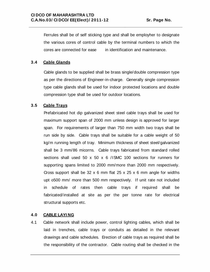
Ferrules shall be of self sticking type and shall be employher to designate
the various cores of control cable by the terminal numbers to which the
cores are connected for ease in identification and maintenance.
3.4 Cable Glands
Cable glands to be supplied shall be brass single/double compression type
as per the directions of Engineer-in-charge. Generally single compression
type cable glands shall be used for indoor protected locations and double
compression type shall be used for outdoor locations.
3.5 Cable Trays
Prefabricated hot dip galvanized sheet steel cable trays shall be used for
maximum support span of 2000 mm unless design is approved for larger
span. For requirements of larger than 750 mm width two trays shall be
run side by side. Cable trays shall be suitable for a cable weight of 50
kg/m running length of tray. Minimum thickness of sheet steel/galvanized
shall be 3 mm/86 micorns. Cable trays fabricated from standard rolled
sections shall used 50 x 50 x 6 /ISMC 100 sections for runners for
supporting spans limited to 2000 mm/more than 2000 mm respectively.
Cross support shall be 32 x 6 mm flat 25 x 25 x 6 mm angle for widths
upt o500 mm/ more than 500 mm respectively. If unit rate not included
in schedule of rates then cable trays if required shall be
fabricated/installed at site as per the per tonne rate for electrical
structural supports etc.
4.0 CABLE LAYING
4.1 Cable network shall include power, control lighting cables, which shall be
laid in trenches, cable trays or conduits as detailed in the relevant
drawings and cable schedules. Erection of cable trays as required shall be
the responsibility of the contractor. Cable routing shall be checked in the

CIDCO OF MAHARASHTRA LTD C.A.No.03/CIDCO/EE(Elect)/2011-12 Sr. Page No.
filed to avoid interference with structures, piping or air-conditioning duct
and minor adjustments shall be done to suit the filed conditions wherever
deemed necessary without any extra cost.
4.2 High voltage, medium voltage and other control and communication
cables shall be separated from each other by adequate spacing or running
through independent pipes, trenches or cable trays, as applicable.
4.3 All cable routes shall be carefully measured and cables cut to the required
lengths, leaving sufficient lengths for the final connection of the cable to
the terminal of the equipment. The various cable lengths cut form the
cable reels shall be carefully selected to prevent undue wastage of cables.
The quantity indicated in the cable schedule is only approximate. The
contractor shall ascertain the exact requirement of cable for a particular
feeder by measuring at site and avoiding interference with structure,
foundation, pipelines or any other works.
4.4 Cables as far as possible shall be laid in complete, uncut lengths from one
termination to the other.
4.5 Cables shall be neatly arranged in the trenches/trays in such manner so
that criss-crossing is avoided and final take off to the motor/switchgear is
facilitated. Arrangement of cables within the trench/trays shall be the
responsibility of the contractor.
4.6 All cables will be identified close to their termination point by cable
numbers as per cable schedule. Cable numbers will be punched on
aluminium straps (2 mm thick) securely fastened to the cable and srapped
around it. Alternatively cable tags shall be circular in construction to
which cable numbers can be conveniently punched. Each underground
cable shall be provided with identify tags of lead securely fastened every
CIDCO OF MAHARASHTRA LTD C.A.No.03/CIDCO/EE(Elect)/2011-12 Sr. Page No.
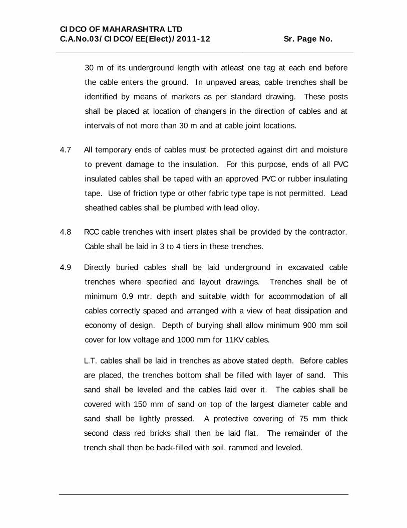
30 m of its underground length with atleast one tag at each end before
the cable enters the ground. In unpaved areas, cable trenches shall be
identified by means of markers as per standard drawing. These posts
shall be placed at location of changers in the direction of cables and at
intervals of not more than 30 m and at cable joint locations.
4.7 All temporary ends of cables must be protected against dirt and moisture
to prevent damage to the insulation. For this purpose, ends of all PVC
insulated cables shall be taped with an approved PVC or rubber insulating
tape. Use of friction type or other fabric type tape is not permitted. Lead
sheathed cables shall be plumbed with lead olloy.
4.8 RCC cable trenches with insert plates shall be provided by the contractor.
Cable shall be laid in 3 to 4 tiers in these trenches.
4.9 Directly buried cables shall be laid underground in excavated cable
trenches where specified and layout drawings. Trenches shall be of
minimum 0.9 mtr. depth and suitable width for accommodation of all
cables correctly spaced and arranged with a view of heat dissipation and
economy of design. Depth of burying shall allow minimum 900 mm soil
cover for low voltage and 1000 mm for 11KV cables.
L.T. cables shall be laid in trenches as above stated depth. Before cables
are placed, the trenches bottom shall be filled with layer of sand. This
sand shall be leveled and the cables laid over it. The cables shall be
covered with 150 mm of sand on top of the largest diameter cable and
sand shall be lightly pressed. A protective covering of 75 mm thick
second class red bricks shall then be laid flat. The remainder of the
trench shall then be back-filled with soil, rammed and leveled.

CIDCO OF MAHARASHTRA LTD C.A.No.03/CIDCO/EE(Elect)/2011-12 Sr. Page No.
As each row of cables is laid in place and before covering with sand every
cables shall be given an insulation test in the presence of Engineer-in-
charge/Owner. Any cable which proves defective shall be replaced before
the next group of cables are laid.
All wall openings shall be effectively sealed after installation of cables to
avoid leakage of water.
4.10 Where cables rise from trenches to motor, control, station, lighting panels
etc., they shall be taken in G.I. pipes for mechanical protection upto a
minimum of 300 mm acboe grade or as shown in the standard drawings.
Cable ends shall be carefully pulled through the conduits to prevent
damge to the cable. Where required, approved cable lubricant shall be
used for this purpose. Where cable enters conduit the cable should be
bent in large radius. Radius shall not be less than the recommended
bending radius of the cables specified by the manufacturer.
Following guide of the pipe fill shall be used for sizing the pipe size:-
a) 1 Cable in pipe : 53% full
b) 2 Cables in pipe : 31% full
c) 3 or more cables : 43% full
d) Multiple cables : 40 % full.
After the cables are installed and all testing is complete, conduit ends
above grade shall be plugged with a suitable weatherproof plastic
compound/PUTTI for sealing purpose. Alternatively G.I. Lids or PVC
bushes shall be employed for sealing purposes. The cost for the same
shall be deemed to have been included in the installation of G.I. pipe and
no separate payment shall be done.
CIDCO OF MAHARASHTRA LTD C.A.No.03/CIDCO/EE(Elect)/2011-12 Sr. Page No.
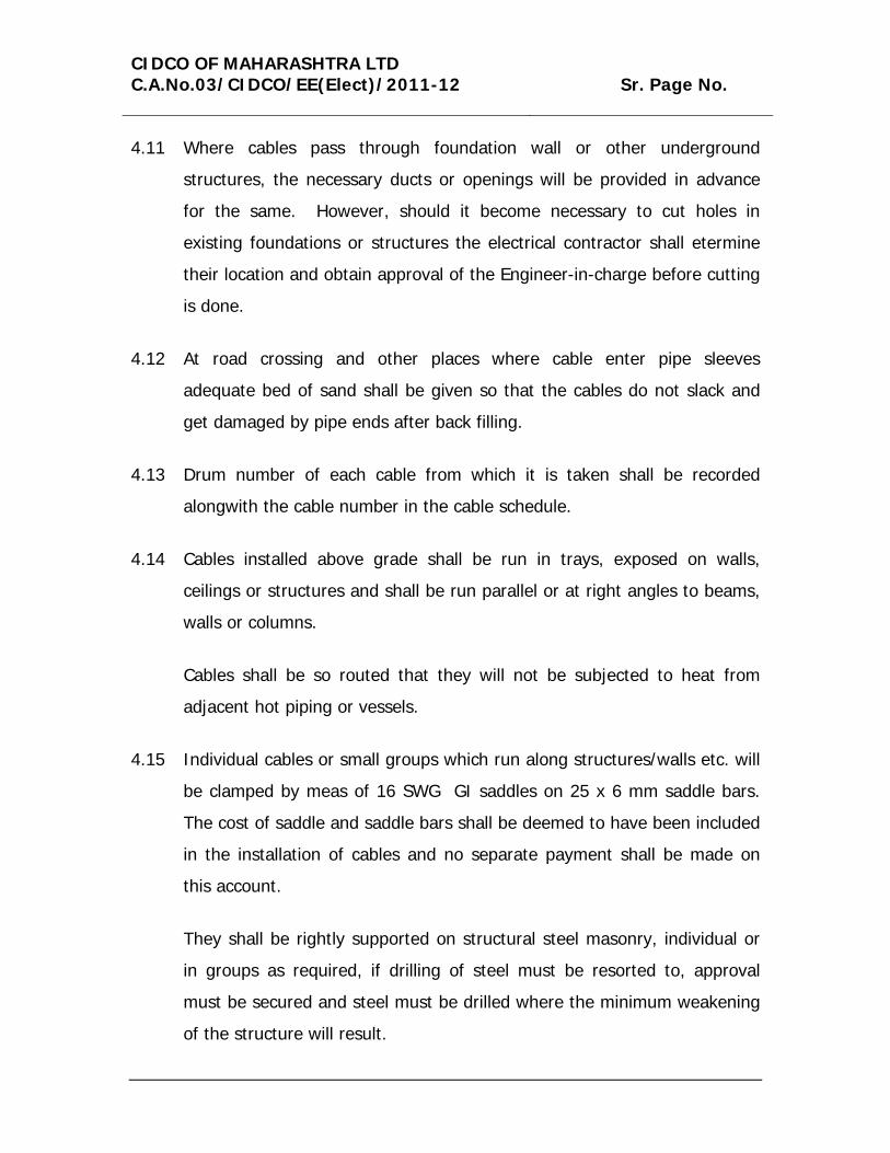
4.11 Where cables pass through foundation wall or other underground
structures, the necessary ducts or openings will be provided in advance
for the same. However, should it become necessary to cut holes in
existing foundations or structures the electrical contractor shall etermine
their location and obtain approval of the Engineer-in-charge before cutting
is done.
4.12 At road crossing and other places where cable enter pipe sleeves
adequate bed of sand shall be given so that the cables do not slack and
get damaged by pipe ends after back filling.
4.13 Drum number of each cable from which it is taken shall be recorded
alongwith the cable number in the cable schedule.
4.14 Cables installed above grade shall be run in trays, exposed on walls,
ceilings or structures and shall be run parallel or at right angles to beams,
walls or columns.
Cables shall be so routed that they will not be subjected to heat from
adjacent hot piping or vessels.
4.15 Individual cables or small groups which run along structures/walls etc. will
be clamped by meas of 16 SWG GI saddles on 25 x 6 mm saddle bars.
The cost of saddle and saddle bars shall be deemed to have been included
in the installation of cables and no separate payment shall be made on
this account.
They shall be rightly supported on structural steel masonry, individual or
in groups as required, if drilling of steel must be resorted to, approval
must be secured and steel must be drilled where the minimum weakening
of the structure will result.
CIDCO OF MAHARASHTRA LTD C.A.No.03/CIDCO/EE(Elect)/2011-12 Sr. Page No.
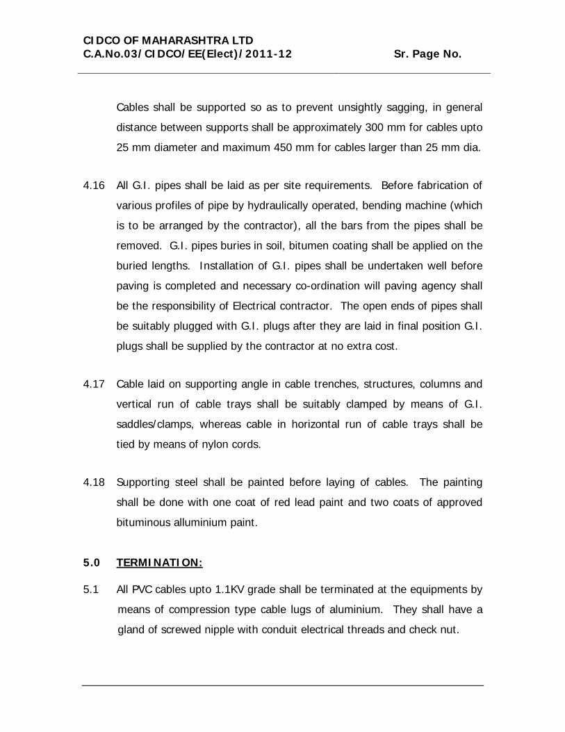
Cables shall be supported so as to prevent unsightly sagging, in general
distance between supports shall be approximately 300 mm for cables upto
25 mm diameter and maximum 450 mm for cables larger than 25 mm dia.
4.16 All G.I. pipes shall be laid as per site requirements. Before fabrication of
various profiles of pipe by hydraulically operated, bending machine (which
is to be arranged by the contractor), all the bars from the pipes shall be
removed. G.I. pipes buries in soil, bitumen coating shall be applied on the
buried lengths. Installation of G.I. pipes shall be undertaken well before
paving is completed and necessary co-ordination will paving agency shall
be the responsibility of Electrical contractor. The open ends of pipes shall
be suitably plugged with G.I. plugs after they are laid in final position G.I.
plugs shall be supplied by the contractor at no extra cost.
4.17 Cable laid on supporting angle in cable trenches, structures, columns and
vertical run of cable trays shall be suitably clamped by means of G.I.
saddles/clamps, whereas cable in horizontal run of cable trays shall be
tied by means of nylon cords.
4.18 Supporting steel shall be painted before laying of cables. The painting
shall be done with one coat of red lead paint and two coats of approved
bituminous alluminium paint.
5.0 TERMINATION:
5.1 All PVC cables upto 1.1KV grade shall be terminated at the equipments by
means of compression type cable lugs of aluminium. They shall have a
gland of screwed nipple with conduit electrical threads and check nut.

CIDCO OF MAHARASHTRA LTD C.A.No.03/CIDCO/EE(Elect)/2011-12 Sr. Page No.
5.2 Power cables shall be identified with red, yellow and blus PVC tapes.
Where copper to aluminium connections are made, necessary bimetallic
washers shall be used. For trip circuit identification additional red ferrules
shall be used only in the particular cores of control cables at the
termination points in the switchgear/control panels and control switches.
5.3 In case of control cables all cores shall be identified at both ends by their
terminal numbers by means of PVC ferrules, or self sticking cable
markers. Wire numbers shall be as per schematic/wiring/inter-connection
diagram. Bidders shall have the samples of PVC ferrules/cable markers
approved before starting the work.
5.4 Where threaded cable gland is screwed into threaded opening of different
size, suitable galvanized threaded reducing bushing shall be used of
approved type, at no extra cost.
5.5 The cable shall be through glands inside the panels or any other electrical
equipment such as motors. The individual cores shall then be dressed
and taken along the cable ways (if provided) or shall be fixed to the
panels with polyethylene straps. Only control cables of single strand and
lighting cables may be directly terminated on the terminals.
In case of termination of cables at the bottom of a panel over a cable
trench having no access from the bottom close fit hole should be drilled in
the bottom plate for all the cables in one line, then bottom plate should
be split in two parts along the center line of holes. After installation of
bottom plate and cables it should be sealed with cold setting compound.
Cables shall be clamped over the open armouring to connect it to earth
bus.

CIDCO OF MAHARASHTRA LTD C.A.No.03/CIDCO/EE(Elect)/2011-12 Sr. Page No.
5.6 Cable leads shall be terminated at the equipment terminals, by means of
crimped type solderless connectors as manufactured by M/s. Dowell
Electro Works or approved equivalent.
Crimping shall be done by hand crimping/hydraulically operated tool and
conducting jelly shall be applied on the conductor. Insulation of the leads
should be removed immediately before the crimping. Conductor surface
shall be cleaned and shall not be left open.
5.7 11, 6.6 and 3.3 KV cables terminations/joints shall be done byu skilled and
experienced jointers duly approved by the owner, if included in the
contract.
6.0 TESTING
6.1 Before energizing, the insulation resistance of every circuit shall be
measured from phase to phase and from phase to ground, This requires
3 measurements if one side is grounded and 6 measurements for 3 phase
circuits.
Where splices or terminations are required in circuits rated above 600
Volts, measure insulation resistance of each length of cable before splicing
and or/terminating. Repeat measurement after splices and/ or
terminations are completed.

CIDCO OF MAHARASHTRA LTD C.A.No.03/CIDCO/EE(Elect)/2011-12 Sr. Page No.
6.2 Measure the insulation resistance of directly buried cable circuits before
cable trenches are back-filled. Repeat measurement after back filling.
6.3 D.C. High voltage test shall be made after installation on the following:-
1) All 1000 Volts grade cables in which straight through joints have
been made.
2) All cables above 1100 V grade. For record purposes test data shall
include the measure values of leakage current verses time.
The D.C. High voltage test shall be performed as detailed below in
the presence of the Engineer-in-charge or his authorized
representative only.
Cables shall be installed in final position with all the straight
through joints complete. Terminations shall be kept unfinished so
that motors, switchgears, transformers etc. are not subjected to
test voltage.
The test voltage and duration shall be as per relevant codes and
practices of Indian Standard Institution.
7.0 H.T. CABLE LAYING 7.1 CABLES LAID IN BUILT UP TRENCHES : 7.1.1 Cables laid in the built-up trenches within the building shall be raised so
as not to lay at the trench bottom. Cables shall be either secured to the
wall by saddles or laid on angle iron brackets or cable trays, ladders,
rack, trough etc. as approved by CIDCO. Where cables are laid on cable
CIDCO OF MAHARASHTRA LTD C.A.No.03/CIDCO/EE(Elect)/2011-12 Sr. Page No.
brackets, the brackets shall not be fixed more than 500 mm. apart to
avoid sag in the cables. Where cables shall be fixed with cable tie or
saddles and shall be at minimum 25 mm. away from side walls and
minimum 150 mm distance shall be observed between two adjacent
cables.
7.1.2 The dimensions of the trenches shall be determined depending upon the
maximum number of cables that is expected to be accommodated.
Wherever specified, trenches shall be filled with fine sand and covered
with RCC or steel chequered trench covers.
7.2 DUCT SYSTEM :
Wherever specified cables shall be laid in underground ducts. The duct
system shall consist of required number of reinforced hume pipes with
simplex joints. The ducts shall be properly anchored to prevent any
movement. The top surface of the cable ducts shall not be less than
100 mm below the ground level. The ducts shall be provided with
inspection manholes at all direction changes and at required regular
intervals of 50 mtr. for drawing the cables. The manholes shall be at
reinforced concrete either cast-in-situ or precast. The manhole covers
shall be RCC cover of suitable weight to withstand the load of the road
vehicle. The ducts shall be properly plugged at the ends to prevent
entry of water, rodents etc. Suitable duct markers shall be placed along
the run of the cable ducts. The duct markers shall be at least be 15
cms. square embedded in concrete, indicating the voltage, number of
ducts and direction of run of the cable be provided in the manholes for
supporting the cables. Proper identification tags shall be provided for
each cable in the manholes.
CIDCO OF MAHARASHTRA LTD C.A.No.03/CIDCO/EE(Elect)/2011-12 Sr. Page No.
7.3 CABLE TRENCHES (EXCAVATED):
7.3.1 The cable trenches shall be excavated 1000 mm below the finished
ground level and shall have a minimum width of 300 mm. for laying of
single cable. When more than one cables are laid in the same trench,
the width of the trench shall be increased such that the spacing
between the cables is 25 cms. and the end cables are at minimum 15
cms. from the side of the trenches. At the turning of the cable route
the trench shall be dug with radius equal to 15 times the cable
diameter.
7.3.2 The trenches shall be cut square with vertical side walls and with
uniform depth. Suitable shoring and propping may be done to avoid
caving in of trench walls. The floor of the trench shall be rammed and
leveled. The bottom of the cable trench shall be prepared with 100mm.
sand bed for laying the cables.
7.3.3 The cables shall be laid in trenches over the rollers. After the cable is
laid and straightened it shall be covered with sand, and RCC half
round/semi circular pipe of appropriate strength & size.
7.3.4 The cable trench then shall be refilled with excavated materials after
removing the stones and other sharp materials and the refilled materials
shall be compacted with light ramming.
7.3.5 Approved cable markers made of G.I. with 15 cms crown shall be
provided along the route of cables at a spacing of 40 – 50 meters and
also at both ends of road crossings or at the cable turning points. The
class, type and No. of cables shall be indicated on the markers.

CIDCO OF MAHARASHTRA LTD C.A.No.03/CIDCO/EE(Elect)/2011-12 Sr. Page No.
7.3.6 Cable shall be laid in hume pipes at all road crossings and in GI pipes at
the wall entries.
7.4 CABLE JOINTING :
7.4.1 Cable jointing shall be done as per the recommendations of the cable
manufacturer. Jointing shall be done by qualified cable jointer. The
location of the cable joint shall not be where the cable takes a bend also
where the soil is loose and shows signs of subsidence.
7.5 CABLE TERMINATION :
7.5.1 All cable termination shall be done in cable end box provided in RMU,
Transformer or any other H.T. equipment.
7.5.2 Cable terminations are to be made with cable heat shrinkable
termination kits of specified approved make only.
7.5.3 Every connection at a cable termination shall be mechanically and
electrically sound and protected against mechanical damage and any
vibration liable to occur shall not impose any harmful mechanical
damage to the cable conductor.
7.6 TESTING OF CABLE BEFORE LAYING AND COMMISSIONING :
7.6.1 All tests shall be carried out in accordance with relevant IS codes of
practice, IE rules.

CIDCO OF MAHARASHTRA LTD C.A.No.03/CIDCO/EE(Elect)/2011-12 Sr. Page No.
7.6.2 100% cable drums shall be checked for continuity and cross continuity
tests to ensure that there is no internal damage to the cable during
transportation.
7.6.3 Installation resistance shall be measured with 1000 V megger between
the cores and all the cores to earth (armour) and results shall be
recorded.
7.6.4 Before cable jointing is done, cable shall be tested for presence of
moisture by dipping a piece of insulation of cable in hot compound of
paraffin was at temperature between 120 –140 degree centigrade. The
presence of moisture is indicated by the formation of bubbles. Only a
single strip of insulation gripped by a pair of tweezers should be used.
7.6.5 After the cables are installed before commissioning it shall be tested for
high DC voltage test. The recommended volts and duration of the test
shall be as per I.E. rules & regulations. However the test voltage and
duration shall be in conformity with standards of local supply
authorities. During high voltage tests all electrical equipments related
to the cable installation must be earthed and adequate clearance shall
be maintained from the other equipments and from work to prevent
flash over.
_______________________ _______________________ Stamp and signature of Contractor
Addl. Chief Engineer (II)
Date :
Date :
CIDCO OF MAHARASHTRA LTD C.A.No.03/CIDCO/EE(Elect)/2011-12 Sr. Page No.
CODES AND STANDARDS
The following codes and standards shall be applicable for continuous
performance of all electrical equipments to be supplied, delivered at site,
erected, tested and commissioning. The electrical equipments offered
shall comply to the relevant Indian Standards Specifications. Fire
Insurance Regulations, Tariff Advisory Committee Regulations, and
particular to Indian Electricity Rules in all respect with all its latest
amendments upto date.
For guidelines to the tenderers, few of the Indian Standards are indicated
below :-
1. IS:116 - Circuit breakers for AC System.
2. IS:159 - Bubars and Busbars connections.
3. IS:3043 - Code of practice of earthing.
4. IS:10116 - Code of practice for installation of switchgear.
5. IS:10116 - Code of practice for selection, installation and maintenance of fuse (upto 650 Volts.)
6. IS:3165 - Potential Transformers.
7. IS:3203 - Climate proofing of electrical equipments.
8. IS:3427 - Metal enclosed switchgear and central gear.
9. IS:3419 - Specification for fittings for rigid PVC non-metallic conduit.
10. IS:3537 - Gas separated relays.
11. IS:3639 - Fittings and accessories for power Transformer.
CIDCO OF MAHARASHTRA LTD C.A.No.03/CIDCO/EE(Elect)/2011-12 Sr. Page No.
12. IS:3837 - Accessories for rigid steel conduits.
13. IS:4064 - Heavy duty Air Break switches and composite. Switch fuse units for voltage and exceeding 100V.
14. IS:4064 - Switch fuse units for Industries etc.
15. IS:4237 - General requirements for switchgears not exceeding 1000 Volts.
16. IS:4615 - Switch socket outlet.
17. IS:5133 (Part-I) - Sheet steel boxed.
18. IS:3070 (Part-I) - Lighting Are stores.
19. IS:2034 - L.T. capacitors.
20. IS:192 - Electric power switchgear for indoor and outdoor installation.
21. IS:PUB 26 - Circuit Breakers.
22. IS:9535 - Specification for conduits for electrical installation.
23. IS:240 (Part-I & II) - for H.T. insulator of 33KV grade and above.
24. IS:335 - Insulating Transformer Oil.
25. IS:374 - Ceiling fans.
26. IS:375 - Marking and arrangement for switchgear boards main connections auxiliary wiring
27. IS:415 - Tungsten filament lamps. 28. IS:692 - Paper insulated cables.
29. IS:694 - PVC insulated cables and cords for
power lighting.

CIDCO OF MAHARASHTRA LTD C.A.No.03/CIDCO/EE(Elect)/2011-12 Sr. Page No.
30. IS:722 - Three phase watt hour meters with MDI
31. IS:732 - Electrical wiring installation (upto 650V)
32. IS:1087 - Single pole tumbler switch 5 Amps.
33. IS:1248 - Direct reading electrical indicating
instruments.
34. IS:1255 - installation and maintenance of paper insulated power cables upto 33 KV)
35. IS:1293 - 3 Pin lugs and sockets outlets.
36. IS:1554 - PVC insulated cables – heavy duty.
37. IS:1567 - Metal clad switches upto 100 Amps.
38. IS:1651 - Lead acid cell batteries.
39. IS:1653 - Rigid steel conduits for electric wiring.
40. IS:1771 - Industrial light fittings with accessories.
41. IS:6600 - Loading of oil immersed transformer.
42. IS:6946 - Reliable (flexible) non-metallic conduits for electrical.
43. IS:7098 (Part-II) - For XLPE type cables.
44. IS:5216 - Guide for safely procedure and practices in electric work.
45. IS:5578 - Guide for marking of insulated conductors.
46. IS: 5792 - 11 kv drop out fuses.
47. IS:5820 - Pre-cast concrete cables covers.
CIDCO OF MAHARASHTRA LTD C.A.No.03/CIDCO/EE(Elect)/2011-12 Sr. Page No.
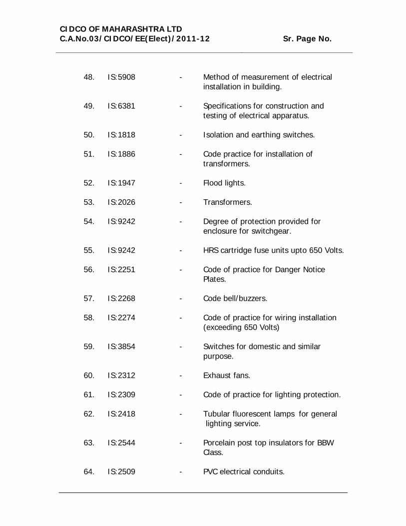
48. IS:5908 - Method of measurement of electrical
installation in building.
49. IS:6381 - Specifications for construction and testing of electrical apparatus.
50. IS:1818 - Isolation and earthing switches.
51. IS:1886 - Code practice for installation of transformers.
52. IS:1947 - Flood lights.
53. IS:2026 - Transformers. 54. IS:9242 - Degree of protection provided for
enclosure for switchgear.
55. IS:9242 - HRS cartridge fuse units upto 650 Volts.
56. IS:2251 - Code of practice for Danger Notice Plates.
57. IS:2268 - Code bell/buzzers. 58. IS:2274 - Code of practice for wiring installation
(exceeding 650 Volts)
59. IS:3854 - Switches for domestic and similar purpose.
60. IS:2312 - Exhaust fans.
61. IS:2309 - Code of practice for lighting protection. 62. IS:2418 - Tubular fluorescent lamps for general
lighting service.
63. IS:2544 - Porcelain post top insulators for BBW Class.
64. IS:2509 - PVC electrical conduits.

CIDCO OF MAHARASHTRA LTD C.A.No.03/CIDCO/EE(Elect)/2011-12 Sr. Page No.
65. IS:2516 - A.C. Circuit breakers.
66. IS:2667 - Fittings for rigid steel conduits for
electrical wiring.
67. IS:2692 - 11 KV drop out fuses.
68. IS:2575 - Enclosed distribution fuse boards and cutouts for voltage upto 1000 V.
69. IS:2705 - Current transformer. 70. IS 14930 II - Double Walled Corrugated pipes of High
Density Polyethylene (HDPE) with couplings, tees, sockets for cable protection.
The entire electrical installation work shall be strictly complied with the codes,
standards, rules and regulations framed under the Indian Electricity Act. Further
it shall be strictly carried out as per the regulations and rules set out by “Tariff
Advisory Committee and/or Fire Insurance Regulations”.
Some of the rules framed under the Indian Electricity Rules, 1956 and all
amendments thereof more particularly complied to :
35, 43, 44, 44-A, 45 (Part), 50, 51, 59, 61 (a), 61 (c), 62, 63 (2), 65, 66, 67, 68,
69 and 92(2).
_______________________ _______________________ Stamp and signature of Contractor
Addl. Chief Engineer (II)
Date :
Date :

CIDCO OF MAHARASHTRA LTD C.A.No.03/CIDCO/EE(Elect)/2011-12 Sr. Page No.
LIST OF APPPROVED MAKES OF ACCESSORIES FOR ELECTRICAL WORKS
Sr. No.
Particulars Makes
1. Submersible Pump /Monoblock pumps
Crompton Greaves, Aqua, Kirloskar, Mather & Platt, Modi, KSB, Kishor, Flowmore, ABS, Grundfos, Flygt Universal Engineers.
2. Ring Main Unit/HT switches & Fuseunit
MEI, Southern, Andrew Yule.
3. C.T./P.T. MSEB approved/Hupken
4. Auto Transformer starter MEI, Kilburn, JMP, Siemens, Andrew Yule, GEC, KEC
5. Trivector Meter MSEB approved
6. Measuring Instruments IMP, AE, UE, MECO, FE, Rishline (L&T), Ashida
7. Current transformer AE, Gilbert & Maxwell, IMP, Siemens SEGC (C.S), Pragati
8. PVC Conduits, PVC Pipes, DWC DHPE pipes
Garware, Pricision, Circlearc, Popular, Prince, Shaktiman, REX Polyextrusion Ltd. Premium Pipes and fittings, Madhu Plast.
9. Ceiling/Table Fans/ Air Circulators
Usha, Crompton, Bajaj, Cinni, Rallies, Orient, Polar, Almonard, Alfa.
10. G.O.D. Switches & Dropout fuse Outfit
Kiran, Pactil, Atlas, Cona Industries, Leader Electricals, Elle Electricals
11. Chain Pulley Block Elephanta, Herculas, WMI
12. Sluice Valve Kirloskar, IVC
13. Butterfly Valve Forbes, IVC
14. Lugs Dowels, Lotus, A.G. Electricals
15. C.I. Pipes Tisco, Sail, Damodar, Shivdurg.

CIDCO OF MAHARASHTRA LTD C.A.No.03/CIDCO/EE(Elect)/2011-12 Sr. Page No.
Sr. No.
Particulars Makes
16. Chlorinator Penwalt, Shree Mitra Purification
17. Motor Protection Relays Universal, Thresold, E.E., Minilac, Siemens, C.S. Telemechanique, Indo- Asian, L&T, Ashidha Electronics Pvt. Ltd.
18. 11KV cable/ 22KV cable CCI, Tropodur, Asian, Nicco, ICL, Gloster, Torrent, Polycab, HVP, Plaza
19. Feeder Pillar/ Mini pillar Popular Brass Metal works, Anil Elect. Ind. Manish, Super or any other manufacturer approved by Dept.
20. Transformer Indo Tech Transformers, Kirloskar, Emco, Bharat Bijlee, Crompton, BSES, Andrew Yule, Pactil, NGEF Delta, KEL, Sharun, Tesla, Argus., Tesla
21. PVC Insulated 1.1kV cable Plaza Cables, Havells’ India Ltd., Vardhaman Cables (Bharat Cab), R.K. Kables Ltd., Revin cable Ltd., Fixolite Wires and Cables, Macro Cables Pvt. Ltd., Dasmesh Cables, Leader Electricals (Leader Leacab), Gemscab Industries Ltd., Polycab, RPG
22. XLPE – LT cables Plaza Cables, Vardhaman Cables (Bharat Cab), Ravin cable Ltd., Macro Cables, Fixolite Wires and Cables, Dasmesh Cables, Central cable Ltd., Gemscab Industries Ltd., Polycab, RPG
23. XLPE – HT Cables Torrent Cables, Plaza Cables, Revin cable Ltd., Central Cable Ltd., Polycab, RPG
24. PVC insulated 1.1kV (HD) cable. Plaza Caes, Vardhaman Cables (Bharat Cab), Havell’s India Ltd., R.K. Kables Ltd., Macro Cables, Dasmesh Cables, Central Cable Ltd., Gemscab Industries Ltd., Polycab

CIDCO OF MAHARASHTRA LTD C.A.No.03/CIDCO/EE(Elect)/2011-12 Sr. Page No.
Sr. No.
Particulars Makes
25. PVC insulated 11kV (HD) cable. Havell’s India Ltd., Central Cable Ltd.,
26. MCB, ELCB, RCCB Indo Asian Fuse Gear,Standard Electrical, Leader Electricals (Leader Aplha Brand), Esprit Switchgear Ltd, Indiana Current Co troll (Versatrip brand), Datar, L&T
27. MCCB Standard Electrical, Spaceage Switchgears, Esprit Switchgear Ltd., Datar, L&T, Indo Asian
28. Isolators/ Disconn-ectors, LV Switch gear/ Switch fuses
Standard Electrical, Kilburn
29. Distribution Board Indo Asian Switchgear, Standard Electrical, Esprit Switchgear Ltd., Indiana Current Control (Versatrip), Super
30. HRC Fuses & bases Indo Asian Switchgear, Havell’s India Ltd., R.B. Commercial Corporation
31. Compact Floures- cent Lamps Indo Asian Fuse gear
32. Alternate Circuit Breaker (acb) Spaceage Switchgears.
33.
PVC Wires, Copper Aluminium Conductor, flexible cables
Philco, Plyroflux, Paragon, Phenolex, Delta., Polyplast, Sundeep, V-Plast, Apex, Silvex, Pagoda, Sapcecab, HMT, Ralicab, Finolex.
34. Fuse switches/ SW fuse L&T, Siemens, Crompton, Telemechanique. Indo-Asian, Havells, EE, HH-ELCON, Standard, KEW, Kalki, Sentinel, Stenly., Samrat
35. Switches/Sockets Kalki, CPL, Anchor, Precission, MK, HME, EEW.
36. Cable Glands HME, EEW,
37. HC Fuse Distribution Board CPL, EE, Stenly, KEW, Kalki, EE, Standard.
38. Air/Oil Circuit Breakers (HT/LT) Kilburn, Easun, MEI, Jyoti, Andrew Yule, Siemens, L&T, GEC, Southern, BHEL, Telemechanique, Crompton.
39. Energy Meters Jaipur.

CIDCO OF MAHARASHTRA LTD C.A.No.03/CIDCO/EE(Elect)/2011-12 Sr. Page No.
Sr. No.
Particulars Makes
40. Capacitor GEC, Khatau-Junkar, Crompton, L&T, Madhav, Atlanta, Prabhodhan, Maladay, Aison (S+M), Samrat.
41. Steel tubular Poles Indian Electric Poles, Bombay Tubes, Nityanand, Rajan Tubes.
42. GI Octagonal Poles Zenith, Tata, Bharat, Bajaj, Saino/ Senzo Engg. Pvt. Ltd., Jenco Industrial Corpn, Shah Pylon, Philips.
43. Terminal Box, Bracket, Junction Box, control pillar.
ELM, United, DVK, Locally fabricated as per CIDCO’s approved drawing/ specifications. Abak Electricals.
44. Street light Luminaries Bajaj, Crompton, Philips, Genlec, Keselec, ELM, Mysore, Wipro, GE-Apar, Canara, Glolite, ECE, Indo-Asian. Vallient Electricals Pvt. Ltd., Fixolite Industrires.
45. Chokes/Ignitors/ Electronic Ballast
Bajaj, Crompton, Philips, Genelec, Keselac, GE-Apar, Glolite, ECE, Indo-Asian. Fixolite Industries, Madhu Gupta & Associates Pvt. Ltd.
46. Power contactors L&T, Siemens, Bharticulter, Hammer, Telemechanique, HH-ELCON, Standard, Kirloskar, Crompton, CS.
47. Lamps Bajaj, Crompton, Philips, Cema, HMT, Electron, Surya, Mysore, Sylvania-Laxman, Solarson, ECE, Indo-Asian. Solarson, ECE, Indo-Asian
48. Rotary/Select or Switches L&T, Siemens, Kaycee, EE, Bisons (ELM)
49. Post top Lantern Philips, Crompton, Glolite, Bajaj, Parimal, Tulip, Kesselec, ECE, Genelec, ELM, Wipro, Indo-Asian.
50. Street Light controller/ Timer L&T (TSQ 100) 24 Hrs. Dial, ELM.
CIDCO OF MAHARASHTRA LTD C.A.No.03/CIDCO/EE(Elect)/2011-12 Sr. Page No.
Sr. No.
Particulars Makes
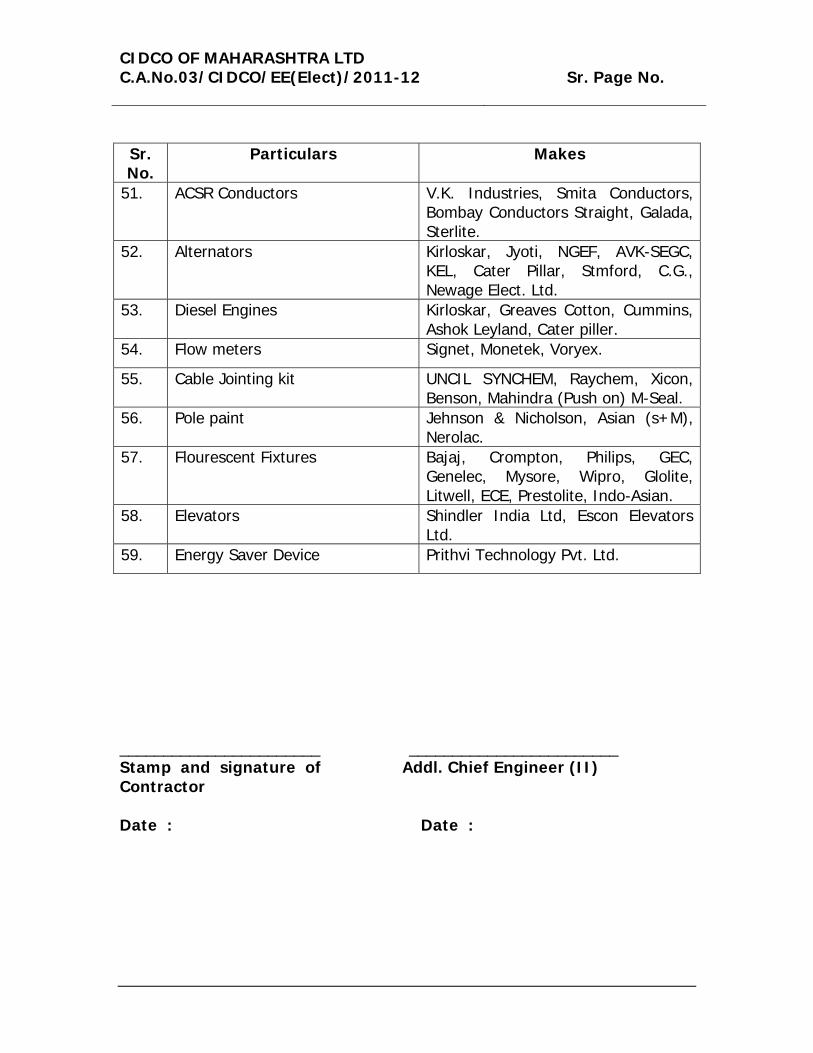
51. ACSR Conductors V.K. Industries, Smita Conductors, Bombay Conductors Straight, Galada, Sterlite.
52. Alternators Kirloskar, Jyoti, NGEF, AVK-SEGC, KEL, Cater Pillar, Stmford, C.G., Newage Elect. Ltd.
53. Diesel Engines Kirloskar, Greaves Cotton, Cummins, Ashok Leyland, Cater piller.
54. Flow meters Signet, Monetek, Voryex.
55. Cable Jointing kit UNCIL SYNCHEM, Raychem, Xicon, Benson, Mahindra (Push on) M-Seal.
56. Pole paint Jehnson & Nicholson, Asian (s+M), Nerolac.
57. Flourescent Fixtures Bajaj, Crompton, Philips, GEC, Genelec, Mysore, Wipro, Glolite, Litwell, ECE, Prestolite, Indo-Asian.
58. Elevators Shindler India Ltd, Escon Elevators Ltd.
59. Energy Saver Device Prithvi Technology Pvt. Ltd.
_______________________ ________________________ Stamp and signature of Contractor
Addl. Chief Engineer (II)
Date :
Date :