scooter tracker installation guide
TRANSCRIPT

Document Number QW_02_0025.001
Scooter Tracker Installation Guide

1 Copyright © 2017 Gemtek Technology Corporation. All Rights Reserved.
QW_02_0025.001
Welcome users. Thanks for choosing our high quality GPS satellite positioning end device model. Please pay attention to the contents of this installation guide prior to setting up the device to ensure accuracy while operating in all aspects. Design and color of the product may vary depending on the actual model. Table of Contents
1. PRODUCT INTRODUCTION ........................................................................................................ 2
2. PRODUCT DESIGN ..................................................................................................................... 2
3. PRODUCT FUNCTIONS .............................................................................................................. 3
1. PRODUCT FEATURES................................................................................................................... 3 2. PRODUCT FUNCTIONS ................................................................................................................. 4
4. PRODUCT ACCESSORIES ......................................................................................................... 5
5. SETUP INSTRUCTIONS .............................................................................................................. 5
1. PREPARATION ................................................................................................................................. 5 2. INSTALLATION .................................................................................................................................. 5 3. INTRODUCING THE END DEVICE CORDS ............................................................................................. 8 4. STEPS FOR DEVICE SETUP: INSTALLATION -> POWER ON .................................................................... 9 5. INDICATOR LIGHT........................................................................................................................... 10
6. DATA FORMAT .......................................................................................................................... 11

2 Copyright © 2017 Gemtek Technology Corporation. All Rights Reserved.
QW_02_0025.001
1. Product Introduction
Our product combines the LoRa wireless communication technology and GPS satellite positioning technology. The end device adapts the highly integrated built-in antenna design which embodies various functions as in ACC detection, Vibration Alert, and Power-out Alarm. A broad input voltage range allows the product to be used on motorcycles and electric vehicles to provide a 24/7 real-time positioning service that is connected to the GPS satellite positioning platform, which therefore contributes to a more comfortable and secure remote management experience.
2. Product Design
Figure 1

3 Copyright © 2017 Gemtek Technology Corporation. All Rights Reserved.
QW_02_0025.001
3. Product Functions
1. Product Features
.ACC Detection performed on vehicles, providing real-time reports on vehicle
status
.Built-in double antenna, high integration design
.Real-time positioning and tracking, applies user preferences based on history
records
.Built-in g-sensor, aides Vibration Alarm performance
.Built-in power switch, broad voltage range 12-60V
.Built-in battery, lodged with Power-out Alarm to prevent illegal cord-cutting
.Built-in sensitivity testing circuit, which will automatically trigger the Low-voltage
Alert to protect the battery when the voltage is lower than 12.3V
Real-time report will be limited to 3 minutes under EU SKU standards.

4 Copyright © 2017 Gemtek Technology Corporation. All Rights Reserved.
QW_02_0025.001
2. Product Functions
Built-in accelerator sensor Vibration Alarm
Satellite GPS positioning, faster
and more accurate
Built-in Battery Automatic Power-off
Alarm, detects power cord
cutting
Double LED Status Display Acknowledges End device
status
ACC Detection Reports real-time vehicle
status
Smart Battery Power Conservation Prevents battery drainage
Displacement Alarm Monitors irregular
placements
Product Functions Chart
5 Copyright © 2017 Gemtek Technology Corporation. All Rights Reserved.
QW_02_0025.001
4. Product Accessories
Power Cord
5. Setup Instructions
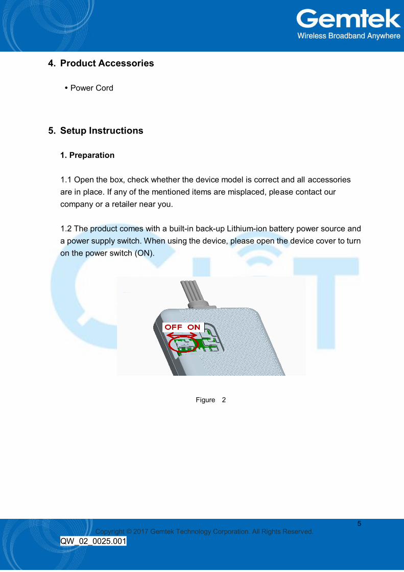
1. Preparation
1.1 Open the box, check whether the device model is correct and all accessories are in place. If any of the mentioned items are misplaced, please contact our company or a retailer near you. 1.2 The product comes with a built-in back-up Lithium-ion battery power source and a power supply switch. When using the device, please open the device cover to turn on the power switch (ON).
Figure 2
6 Copyright © 2017 Gemtek Technology Corporation. All Rights Reserved.
QW_02_0025.001
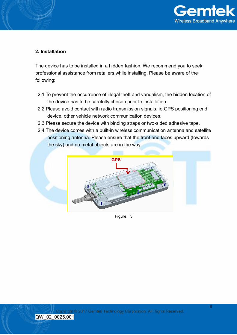
2. Installation
The device has to be installed in a hidden fashion. We recommend you to seek professional assistance from retailers while installing. Please be aware of the following: 2.1 To prevent the occurrence of illegal theft and vandalism, the hidden location of
the device has to be carefully chosen prior to installation. 2.2 Please avoid contact with radio transmission signals, ie.GPS positioning end
device, other vehicle network communication devices. 2.3 Please secure the device with binding straps or two-sided adhesive tape. 2.4 The device comes with a built-in wireless communication antenna and satellite
positioning antenna. Please ensure that the front end faces upward (towards the sky) and no metal objects are in the way.
Figure 3

7 Copyright © 2017 Gemtek Technology Corporation. All Rights Reserved.
QW_02_0025.001
Recommended location for installation: Electric vehicle/Motorcycle – Dashboard or concealed compartment underneath the back seat.
Figure 4
Figure 5

8 Copyright © 2017 Gemtek Technology Corporation. All Rights Reserved.
QW_02_0025.001
3. Definition of the End Device Power Cords
.Red cord – connects to the positive terminal of the power source
.Black cord – connects to the negative terminal of the power source
.Orange cord – connects to the ACC
.Yellow cord – relay cable (current version is disabled)
Figure 6

9 Copyright © 2017 Gemtek Technology Corporation. All Rights Reserved.
QW_02_0025.001
Please use the original company manufactured power source. The red cord is the positive terminal; the black cord is the negative terminal. When connecting the negative terminal of the power source, please select an individual ground wire. Please do not share ground wires with other devices. If the ACC anti-theft feature is required, please ensure that the ACC cord is connected. The device will verify the status of the ACC cord to determine whether the device is in protection mode. If the ACC cord is not connected, the device that is installed inside the vehicle will be in protection mode, which will trigger the Vibration Alarm when the vehicle is in steering motion.
4. Steps for Device Setup: Installation -> Power On
Installation: While installing, please ensure that the satellite positioning antenna is facing upward towards the sky. The device must be installed in a spot where no metal objects are in the way to disrupt the transmission. Power On: Connect the cords accordingly as instructed. Switch on the power to turn on the device.
10 Copyright © 2017 Gemtek Technology Corporation. All Rights Reserved.
QW_02_0025.001
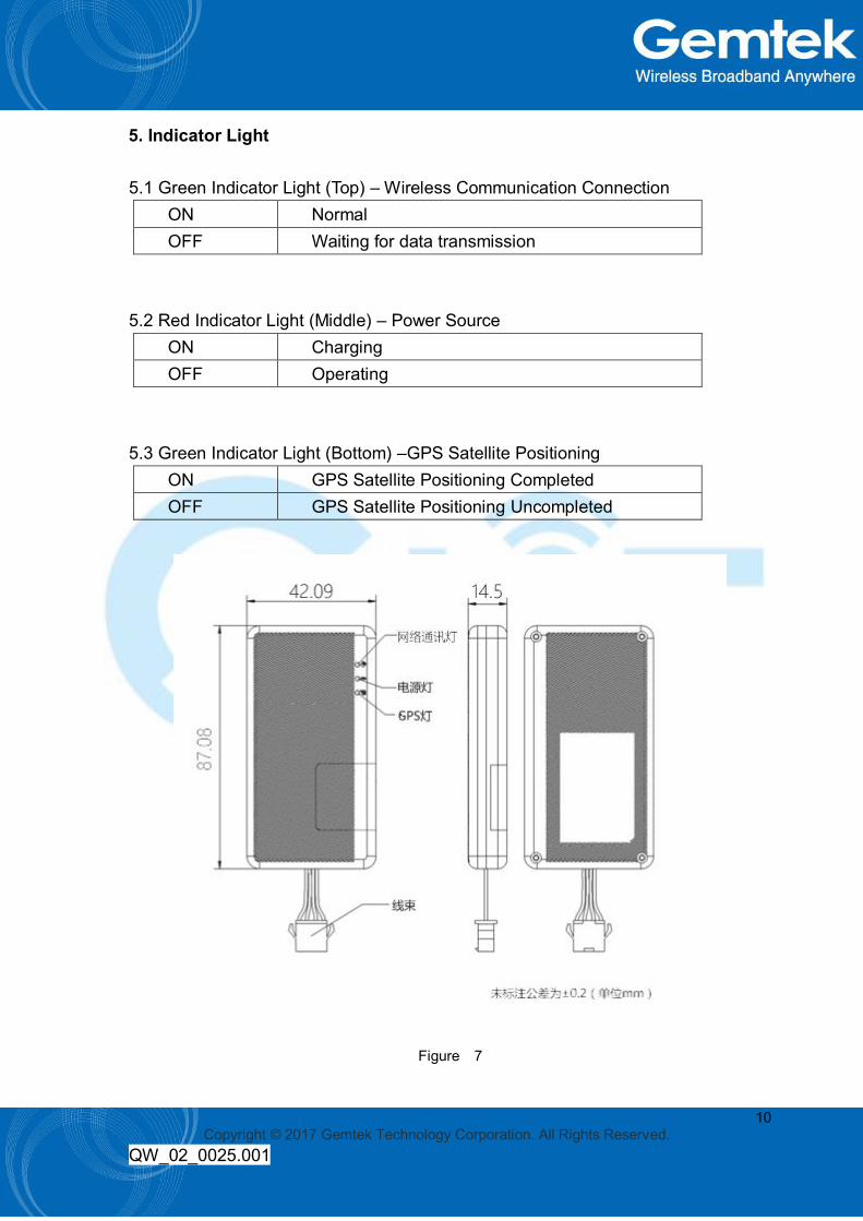
5. Indicator Light
5.1 Green Indicator Light (Top) – Wireless Communication Connection ON Normal OFF Waiting for data transmission
5.2 Red Indicator Light (Middle) – Power Source
ON Charging OFF Operating
5.3 Green Indicator Light (Bottom) –GPS Satellite Positioning
ON GPS Satellite Positioning Completed OFF GPS Satellite Positioning Uncompleted
Figure 7

11 Copyright © 2017 Gemtek Technology Corporation. All Rights Reserved.
QW_02_0025.001
6. Data Format
Start Address Definition Length(byte) Description
0 Alert 1 Refer to Table1 *
1 Status 1 Refer to Table2 *
2 Latitude 4
Value in degrees multiplied by 10 to the
6th power,one millionth of a degree
accuracy.
6 Longitude 4
Value in degrees multiplied by 10 to the
6th power,one millionth of a degree
accuracy.
* Table 1 Alert
Bit Definition Description
0 1:Vehicle being
moved irregularly
Clear alarm after receiving response(Elapsed time until alarm
cleared: 300 M)
1 1:Vibration Alert Elapsed time until alarm cleared
3 1:End Device
Power Loss Elapsed time until alarm cleared
4 N/A
5 N/A
6 N/A
7 N/A

12 Copyright © 2017 Gemtek Technology Corporation. All Rights Reserved.
QW_02_0025.001
* Table 2 Status
Bit Definition
0 0:ACC Off, 1:ACC On
1 0:Not Positioned, 1:Positioned
2 0:North Latitude, 1:South Latitude
3 0:East Longitude, 1:West Longitude
4 N/A
5 N/A
6 N/A
7 N/A
The data format defines the uplink format of scooter tracker and the function of the data if the data needs to be transferred to a meaningful format.