scm-7617-038 application note function blocks for … si canopen user manual hms scm-1200-005 1.10...
TRANSCRIPT

Application Note 1 SI CANopen Function Blocks
SCM-7617-038 Rev 1.12
HMS Industrial Networks AB Page 1 (29)
Application Note
1 SI CANopen Function Blocks

Application Note 1 SI CANopen Function Blocks
SCM-7617-038 Rev 1.12
HMS Industrial Networks AB Page 2 (29)

Application Note 1 SI CANopen Function Blocks
SCM-7617-038 Rev 1.12
HMS Industrial Networks AB Page 3 (29)
Important user information This document is intended to provide a good understanding of the function block functionality offered with the 1 SI CANopen Module for ET200S.
The reader of this document is expected to be familiar with high level software design, and communication systems in general. The use of advanced CANopen-specific functionality may require in-depth knowledge in CANopen networking internals and/or information from the official CANopen specifications. In such cases, the people responsible for the implementation of this product should either obtain the CANopen specification to gain sufficient knowledge or limit their implementation in such a way that this is not necessary.
Liability
Every care has been taken in the preparation of this application note. Please inform HMS Industrial Networks AB of any inaccuracies or omissions. The data and illustrations found in this document are not binding. We, HMS Industrial Networks AB, reserve the right to modify our products in line with our policy of continuous product development. The information in this document is subject to change without notice and should not be considered as a commitment by HMS Industrial Networks AB. HMS Industrial Networks AB assumes no responsibility for any errors that may appear in this document.
There are many applications of this product. Those responsible for the use of this device must ensure that all the necessary steps have been taken to verify that the applications meets all performance and safety requirements including any applicable laws, regulations, codes, and standards
HMS Industrial Networks AB will under no circumstances assume liability or responsibility for any problems that may arise as a result from the use of undocumented features, timing, or functional side effects found outside the documented scope of this product. The effects caused by any direct or indirect use of such aspects of the product are undefined, and may include e.g. compatibility issues and stability issues.
The examples and illustrations in this document are included solely for illustrative purposes. Because of the many variables and requirements associated with any particular implementation, HMS Industrial Networks AB cannot assume responsibility for actual use based on these examples and illustrations.
Intellectual Property Rights
HMS Industrial Networks AB has intellectual property rights relating to technology embodied in the product described in this document. These intellectual property rights may include patents and pending patent applications in the US and other countries.
Trademark Acknowledgements
All trademarks are the property of their respective holders.

Application Note 1 SI CANopen Function Blocks
SCM-7617-038 Rev 1.12
HMS Industrial Networks AB Page 4 (29)
Document history
Revision Date Description Author 1.00 2009-12-01 Created Lars-Åke Väldesjö 1.10 2010-01-18 Example is improved Lars-Åke Väldesjö 1.11 2010-02-25 Explaining texts and Step 7 project are
improved Lars-Åke Väldesjö
1.12 2010-03-30 Text adjustments Lars-Åke Väldesjö
Referenced documents Document name Author Document id. Revision
1 SI CANopen User Manual HMS SCM-1200-005 1.10
More information about the product The latest information can be downloaded from www.et200can.com.

Application Note 1 SI CANopen Function Blocks
SCM-7617-038 Rev 1.12
HMS Industrial Networks AB Page 5 (29)
Contents 1. Requirements ............................................................................................................................................ 6
2. Solution overview ..................................................................................................................................... 7
3. How to import blocks into the STEP7 project ....................................................................................... 8
4. Start using the example .......................................................................................................................... 10
5. Fragmented I/O ...................................................................................................................................... 11 5.1. Hardware configuration .................................................................................................................... 11 5.2. How to configure the Fragmentation block ...................................................................................... 12
5.2.1. Master mode ............................................................................................................................. 12
5.2.2. Slave mode ............................................................................................................................... 14
6. Read SDO ................................................................................................................................................ 16 6.1. How to configure the Read SDO block ............................................................................................ 16 6.2. Other suggestion of use for “Read SDO” ......................................................................................... 18
7. Write SDO ............................................................................................................................................... 18 7.1. How to configure the Write SDO block ........................................................................................... 18 7.2. Other suggestion of use for “Write SDO” ........................................................................................ 20
8. Upload Configuration from 1 SI CANopen master ............................................................................. 20 8.1. How to configure the Upload Configuration block .......................................................................... 20
9. Download Configuration to 1 SI CANopen master ............................................................................. 22 9.1. How to configure the Download Configuration blocks .................................................................... 22 9.2. The use of OB83 to start Download Configuration .......................................................................... 24
9.2.1. Insert/Remove Module Interrupt(OB83) .................................................................................. 24
9.2.2. OB83 Code in example ............................................................................................................ 24
10. The use of OB82 to get Group diagnostics interrupt ...................................................................... 26 10.1. Diagnostic Interrupt (OB82) ........................................................................................................ 26 10.2. OB82 Code in example ................................................................................................................ 27
11. Variables in VAR table “defrag 40-40” in example ........................................................................ 28

Application Note 1 SI CANopen Function Blocks
SCM-7617-038 Rev 1.12
HMS Industrial Networks AB Page 6 (29)
1. Requirements The mounting and configuration of the 1 SI CANopen Module for ET200S is done following these steps:
1.Mounting
2.Configuring the ET200S Distributed I/O System to include the module ( See “ET200S Distributed I/O System Configuration” in the User manual)
3.Setting the parameters of the module ( See “ET200S Distributed I/O System Configuration” in the User manual)
4.Configuring the CANopen network, including the module (See “CANopen Network Configuration” in the User manual)
The following items are needed to perform the installation according to the example file:
Description Name / Type Version
Hardware
Siemens ET200S rack Either IM-type connected to PLC or CPU-type as standalone. Se further information in manual under appendix “Siemens Interface Modules Compatibility”
n.a.
Power module
Input module
Output module
1 SI CANopen Module configured as master 020570-B 1.09 or later
1 SI CANopen Module configured as slave 020570-B 1.09 or later
Software
Siemens SIMATIC STEP7 tool n.a. V5.4 SP 5 or later
PORT CANopen Configuration Manager 020820-B 1.4.0.2 or later
USB adapter for above 020810-B
PLC Function blocks From www.et200can.com 1.04 or later
HSP 2066 (STEP7 configuration file) or GSD files for the 1 SI CANopen Module
From www.et200can.com 1.00 or later
EDS configuration file for the 1 SI CANopen Module
From www.et200can.com 1.03 or later
Other
CANopen cables n.a. n.a.
PLC configuration cable n.a. n.a.

Application Note 1 SI CANopen Function Blocks
SCM-7617-038 Rev 1.12
HMS Industrial Networks AB Page 7 (29)
2. Solution overview This application note describes how to import, compile and use the Function blocks available for download from www.et200can.com
It also refers to a working example consisting of a STEP7 project and a PORT CCM project.
The contents describe step by step how a configuration is done. This document assumes the reader is familiar with industrial communication as CANopen, Siemens STEP7 and PORT CANopen Configuration Manager.

Application Note 1 SI CANopen Function Blocks
SCM-7617-038 Rev 1.12
HMS Industrial Networks AB Page 8 (29)
3. How to import blocks into the STEP7 project The function blocks for Fragmented I/O, SDO-Read, SDO-Write, Upload configuration and Download configuration supported from HMS has to be imported and compiled into your S7 project.
This is done by following the steps below.
Figure 1 Select external source for blocks.
1. Select Sources 2. Right click in white area and select “Insert New Object” from “External Source”
Figure 2 Select files.
3. Select the files needed and press OPEN

Application Note 1 SI CANopen Function Blocks
SCM-7617-038 Rev 1.12
HMS Industrial Networks AB Page 9 (29)
Figure 3 Compile Blocks.
4. Mark the files, right click and select Compile Note: English language is required in STEP7 for the compilation to succeed.
Figure 4 Insert Block from “FB blocks”.
5. Close "compile windows" and blocks can be selected from FB blocks. They have now been given numbers as below: FB101: Named “Upload Configuration” in symbol table in example code. FB102: Named “Download Configuration” in symbol table in example code. FB103: Named “Fragmented I/O” in symbol table in example code. FB104: Named “Read SDO” in symbol table in example code. FB105: Named “Write SDO” in symbol table in example code.

Application Note 1 SI CANopen Function Blocks
SCM-7617-038 Rev 1.12
HMS Industrial Networks AB Page 10 (29)
4. Start using the example In the example two 1 SI CANopen Modules are used. One module is configured in master mode and one in slave mode. They are configured with 40 bytes of input data and 40 bytes of output data each. The 40 bytes of CANopen data from master (CANopen node ID 1) is received and looped back by the slave (CANopen node ID 2).
Memory bit M44.7 controls the loop in the slave module, if set to FALSE loop is enabled.
The modules are in fragmentation mode and use the Function Block “Fragmented I/O” to handle the transfer of data.
There are also examples for the Function blocks “Read SDO”, “Write SDO, “Upload Configuration” and “Download Configuration”.
Connect modules and EMS CANopen USB adapter together with appropriate CANopen cable.
Start the PLC-rack
Download STEP7 program blocks and hardware configuration to the PLC (project stored under “1_SI_1_11 Block example”).
Send CANopen configuration file via PORT CCM to the net. The example configuration that downloads concise files is stored in “PORT CCM 1 SI 40 to 1 SI 40.net”.
To test Configuration Upload and Download the following steps has to be performed: 1) Concise files for the modules have to be saved in non volatile memory in Master module at end of
configuration via CCM. 2) Upload configuration from Master module to PLC-memory. 3) Send “load” to object 1011h in both Master and Slave module followed by Reset or Repower to
restore default configuration. 4) Now configuration can be downloaded from PLC to the empty Master module which will then
configure all modules on the CANopen network.

Application Note 1 SI CANopen Function Blocks
SCM-7617-038 Rev 1.12
HMS Industrial Networks AB Page 11 (29)
5. Fragmented I/O If more CANopen data than module block size (4, 8, 16 or 32 bytes I/O) is required, Fragmented I/O can be used.
5.1. Hardware configuration When the hardware is set up the backplane size of the module has to be defined. This is done by selecting that module from “hardware list” under “Special modules”, see below.
Figure 5 Hardware configuration, hardware list.
In this example a 4 byte 1 SI CANopen Module is used.
Figure 6 Setting properties for the 1 SI CANopen Module.
Start address for the four Input and Output Process data mode is changed to Fragmented. bytes is set to 32 decimal in this example. COP data size is set to 40 in both directions. All other values are kept as default.

Application Note 1 SI CANopen Function Blocks
SCM-7617-038 Rev 1.12
HMS Industrial Networks AB Page 12 (29)
5.2. How to configure the Fragmentation block
5.2.1. Master mode Load Function Block “Fragmented I/O” into a Network and set input and output data.
Figure 7 Fragmented I/O block for Master
Application Note 1 SI CANopen Function Blocks
SCM-7617-038 Rev 1.12
HMS Industrial Networks AB Page 13 (29)
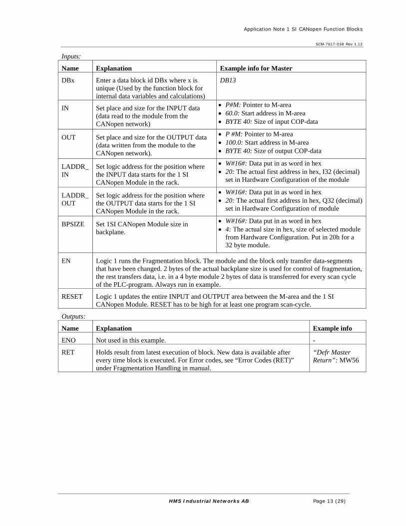
Inputs:
Name Explanation Example info for Master
DBx Enter a data block id DBx where x is unique (Used by the function block for internal data variables and calculations)
DB13
IN Set place and size for the INPUT data (data read to the module from the CANopen network)
• P#M: Pointer to M-area • 60.0: Start address in M-area • BYTE 40: Size of input COP-data
OUT Set place and size for the OUTPUT data (data written from the module to the CANopen network).
• P #M: Pointer to M-area • 100.0: Start address in M-area • BYTE 40: Size of output COP-data
LADDR_IN
Set logic address for the position where the INPUT data starts for the 1 SI CANopen Module in the rack.
• W#16#: Data put in as word in hex • 20: The actual first address in hex, I32 (decimal)
set in Hardware Configuration of the module
LADDR_OUT
Set logic address for the position where the OUTPUT data starts for the 1 SI CANopen Module in the rack.
• W#16#: Data put in as word in hex • 20: The actual first address in hex, Q32 (decimal)
set in Hardware Configuration of module
BPSIZE Set 1SI CANopen Module size in backplane.
• W#16#: Data put in as word in hex • 4: The actual size in hex, size of selected module
from Hardware Configuration. Put in 20h for a 32 byte module.
EN Logic 1 runs the Fragmentation block. The module and the block only transfer data-segments that have been changed. 2 bytes of the actual backplane size is used for control of fragmentation, the rest transfers data, i.e. in a 4 byte module 2 bytes of data is transferred for every scan cycle of the PLC-program. Always run in example.
RESET Logic 1 updates the entire INPUT and OUTPUT area between the M-area and the 1 SI CANopen Module. RESET has to be high for at least one program scan-cycle.
Outputs:
Name Explanation Example info
ENO Not used in this example. -
RET Holds result from latest execution of block. New data is available after every time block is executed. For Error codes, see “Error Codes (RET)” under Fragmentation Handling in manual.
“Defr Master Return”: MW56

Application Note 1 SI CANopen Function Blocks
SCM-7617-038 Rev 1.12
HMS Industrial Networks AB Page 14 (29)
5.2.2. Slave mode Load Function Block “Fragmented I/O” into a Network and set input and output data.
Figure 8 Fragmented I/O block for Slave

Application Note 1 SI CANopen Function Blocks
SCM-7617-038 Rev 1.12
HMS Industrial Networks AB Page 15 (29)
Inputs:
Name Explanation Example info for Slave
DBx Enter a data block id DBx where x is unique (Used by the function block for internal data variables and calculations)
DB12
IN Set place and size for the INPUT data (data read to the module from the CANopen network)
• P#M: Pointer to M-area • 140.0: Start address in M-area • BYTE 40: Size of input COP-data
OUT Set place and size for the OUTPUT data (data written from the module to the CANopen network).
• P #M: Pointer to M-area • 182.0: Start address in M-area • BYTE 40: Size of output COP-data
LADDR_IN
Set logic address for the position where the INPUT data starts for the 1 SI CANopen Module in the rack.
• W#16#: Data put in as word in hex • 40: The actual first address in hex, I64 (decimal)
set in Hardware Configuration of the module
LADDR_OUT
Set logic address for the position where the OUTPUT data starts for the 1 SI CANopen Module in the rack.
• W#16#: Data put in as word in hex • 40: The actual first address in hex, Q64 (decimal)
set in Hardware Configuration of module
BPSIZE Set 1SI CANopen Module size in backplane.
• W#16#: Data put in as word in hex • 4: The actual size in hex, size of selected module
from Hardware Configuration. Put in 20h for a 32 byte module.
EN Logic 1 runs the Fragmentation block. The module and the block only transfer data-segments that have been changed. 2 bytes of the actual backplane size is used for control of fragmentation, the rest transfers data, i.e. in a 4 byte module 2 bytes of data is transferred for every scan cycle of the PLC-program. Always run in example.
RESET Logic 1 updates the entire INPUT and OUTPUT area between the M-area and the 1 SI CANopen Module. RESET has to be high for at least one program scan-cycle.
Outputs:
Name Explanation Example info
ENO Not used in this example. -
RET Holds result from latest execution of block. New data is available after every time block is executed. For Error codes, see “Error Codes (RET)” under Fragmentation Handling in manual.
“Defr Slave Return”: MW58

Application Note 1 SI CANopen Function Blocks
SCM-7617-038 Rev 1.12
HMS Industrial Networks AB Page 16 (29)
6. Read SDO Note: This function is only supported by the 1 SI CANopen Module in master mode!
6.1. How to configure the Read SDO block Load Function Block “Read SDO” into a Network and set input and output data.
In the example Index 1F82h is read from the master itself to get the NMT state it is in (operational could indicate that network is up and running).
(Index 1F82h could be written to with “Write SDO” for example to set the complete network in Operational, or to Reset a node. See the manual for more detailed information.)
Figure 9 Read SDO block
Note: Constants used above for NODE, INDEX and SUB can be replaced with variables as MWx for NODE and INDEX and MBx for SUB. This makes it possible to use same block to read different SDO:s. In VAR-table “defrag 40-40” in example row 2-4 holds variables that can be used to test this.
Note: In the example a pulse is generated at input “REQ” every tenth second by a timer in network 9. It can be stopped by setting bit M10.7 to TRUE in VAR-table “defrag 40-40”.

Application Note 1 SI CANopen Function Blocks
SCM-7617-038 Rev 1.12
HMS Industrial Networks AB Page 17 (29)
Inputs:
Name Explanation Example info
DBx Enter a data block id DBx where x is unique (Used by the function block for internal data variables and calculations)
DB3
REQ Logic 1 for one scan cycle of the PLC-program starts the Read SDO request (see RET below for handling instructions for REQ)
“Read SDO Param REQ M10.5”: M10.5
ID Logic address for the position where the INPUT data starts for the 1 SI CANopen Module in the rack.
• DW#16#: Data is put in as doubleword in hex • 20: The actual first address in hex, I32 (decimal)
set in Hardware Configuration of the module
SLOT Defines which slot is used on the PROFIBUS/PROFINET/Backplane network. This parameter has to be unique for each of the SDO requests running simultaneously as the answer on the request is put in the slot where the request was placed. Valid values: 0 - 7
• W#16#: Data put in as word in hex • 1: Number of used slot
NODE Node ID of the CANopen Module where SDO read is to be performed. Node ID 0 always address the CANopen master, even when the CANopen master has another Node ID
1: Node ID for Master (Variable MWx could be used instead of constant)
INDEX Object index to be read • W#16#: Data put in as word in hex • 1F82: The SDO index read (Request NMT state)
(Variable MWx could be used instead of constant)
SUB Object sub index to be read • B#16#: Data put in as byte in hex • 1: The SDO sub index read (Node ID for master)
(Variable MBx code be used instead of constant)
DATA Place and size of the location to write the answer
• P#M: Pointer to M-area • 225.0: Start address in M-area • BYTE 20: Maximum size to use in M-area
EN Logic 1 runs the Read SDO block Always run
Outputs:
Name Explanation Example info
ENO Not used in this example. -
SIZE Number of bytes that have been read. “Read SDO Param Size”: MW13
BUSY If the request is not finished within one scan cycle, BUSY turns TRUE and stays TRUE until the request is finished, when it returns to FALSE.
“Read SO Param Busy M0.4”: M0.4
RET Holds result from execution of block. Available when BUSY turns FALSE, until REQ is set to TRUE. For Error codes, see “Error Codes (RET)” under SDO Read/Write in manual.
“Read SDO Param Return”: MW15

Application Note 1 SI CANopen Function Blocks
SCM-7617-038 Rev 1.12
HMS Industrial Networks AB Page 18 (29)
6.2. Other suggestion of use for “Read SDO” Another example for the use of “Read SDO” is to read out generic data objects from other slaves (similar to Index 2000h to 201Fh in the 1 SI CANopen Module) instead of having the data mapped in a receive PDO and reserving space in the backplane area of the 1 SI CANopen Module. This is normally used for parameters that are rarely updated on the CANopen network to decrease the network load.
7. Write SDO Note: This function is only supported by the 1 SI CANopen Module in master mode!
7.1. How to configure the Write SDO block Load Function Block “Write SDO” into a Network and set input and output data.
In the example “load” is written to Index 1011h (Restore parameters) in the slave, node 2, to restore the out of box configuration of the slave.
Figure 10 Write SDO block
Note: Constants used above for NODE, INDEX and SUB can be replaced with variables as MWx for NODE and INDEX and MBx for SUB. This makes it possible to use same block to write different SDO:s. In VAR-table “defrag 40-40” in example row 2-4 holds variables that can be used to test this.
Note: To check that Upload and Download concise blocks works load could be sent to the master by changing NODE to 1 in example in OB1, The master will then be reset to default configuration after repower. (If master is physically removed and then replaced after some seconds, the OB1 code will start reconfigure the master from saved concise files. See chapter 8 and 10.)

Application Note 1 SI CANopen Function Blocks
SCM-7617-038 Rev 1.12
HMS Industrial Networks AB Page 19 (29)
Inputs:
Name Explanation Example info
DBx Enter a data block id DBx where x is unique (Used by the function block for internal data variables and calculations)
DB5
REQ Logic 1 for one scan cycle of the PLC-program starts the Write SDO request (see RET below for handling instructions for REQ)
“Write Pulse SDO M0.7”: M0.7
ID Logic address for the position where the INPUT data starts for the 1 SI CANopen Module in the rack.
• DW#16#: Data is put in as doubleword in hex • 20: The actual first address in hex, I32 (decimal)
set in Hardware Configuration of the module
SLOT Defines which slot is used on the PROFIBUS/PROFINET/Backplane network. This parameter has to be unique for each of the SDO requests running simultaneously as the answer on the request is put in the slot where the request was placed. Valid values: 0 - 7
• W#16#: Data put in as word in hex • 2: Number of used slot
NODE Node ID of the CANopen module where SDO read is to be performed. Node ID 0 always address the CANopen master, even when the CANopen master has another Node ID
2: Node ID for slave where data is written
INDEX Object index to be written • W#16#: Data put in as word in hex • 1011: hex for the SDO index (Restore
parameters)
SUB Object sub index to be written • B#16#: Data put in as byte in hex • 1: for the SDO sub index 1
DATA Place and size of the location to read the outgoing data
• P#M: Pointer to M-area • 235.0: Start address in M-area • BYTE 4: Size to be written in M-area
(Value 6C6F6164h is put into these four bytes to represent the ASCII values for “load”.)
EN Logic 1 runs the Write SDO block Always run
Outputs:
Name Explanation Example info
ENO Not used in this example. -
BUSY If the request is not finished within one scan cycle, BUSY turns TRUE and stays TRUE until the request is finished, when it returns to FALSE.
“Write SDO Busy M0.5”: M0.5
RET Holds result from execution of block. Available when BUSY turns FALSE, until REQ is set to TRUE. For Error codes, see “Error Codes (RET)” under SDO Read/Write in manual.
“Write SDO error MW5”: MW5

Application Note 1 SI CANopen Function Blocks
SCM-7617-038 Rev 1.12
HMS Industrial Networks AB Page 20 (29)
7.2. Other suggestion of use for “Write SDO” Another use of “Write SDO” is to write in generic data objects in other slaves (similar to Index 2100h to 211Fh in 1 SI CANopen Module) instead of having the data mapped in a transmit PDO that occupies space in the backplane are of the 1 SI CANopen Module. This is normally used for parameters that are rarely updated on the CANopen network to decrease the network load.
8. Upload Configuration from 1 SI CANopen master Note: This function is only supported by the 1 SI CANopen Module in master mode!
The 1 SI CANopen Module for ET200S can be removed and replaced with other hardware without turning off the power. To be able to restart accurately and fast, the configuration of the CANopen Network, concise files stored in object 1F22h, can be uploaded to the PLC after configuration and downloaded to the new hardware once this is attached to the rack. The upload of the configuration to PLC is performed by “Upload Configuration” block and download by “Download Configuration” block. Maximum size for concise files in the 1 SI CANopen Module is 196k byte.
Note: After configuration is performed by external configurator “save” has to be sent to object 1010h in the master module from the configurator to generate a CRC in the master module that upload block reads from. The uploaded data is checked against this CRC.
Note: If save is not performed the configuration, including concice files, will be lost at powercycling.
8.1. How to configure the Upload Configuration block Load Function Block “Upload Configuration” into a Network and set input and output data. In this example it is written in STL-format to show how that could lock like.
Figure 11 Network with “Download configuration” and “Upload configuration”
Upload is initiated by setting bit “Upload Start” (M7.4) in example above.

Application Note 1 SI CANopen Function Blocks
SCM-7617-038 Rev 1.12
HMS Industrial Networks AB Page 21 (29)
Inputs:
Name Explanation Example info
DBx Enter a data block id DBx where x is unique (Used by the function block for internal data variables and calculations)
DB21: for Upload
REQ Logic 1 for one scan cycle of the PLC-program starts the request (see RET below for handling instructions for REQ)
“Upload start”: M7.4
ID Logic address for the position where the INPUT data starts for the 1 SI CANopen Module in the rack.
• DW#16#: Data is put in as doubleword in hex • 20: The actual first address in hex, I32
(decimal) set in Hardware Configuration of the module
DBSTART The number of the first DB (Data Block) of a maximum of four that concise files are stored in
8: DB8, DB9, DB10 and DB11 will be used for concise data. (Do not use these DB:s for anything else. Configuration blocks will erase all data in them)
DBSIZE Size of the data blocks that are used to store data. Valid values are 262 – 50000 decimal.
• W#16#: Data put in as word in hex • 3000: Number of used bytes in hex (12288
bytes)
Outputs:
Name Explanation Example info
ENO Not used in this example. -
BUSY If the request is not finished within one scan cycle, BUSY turns TRUE and stays TRUE until the request is finished, when it returns to FALSE.
“Upload Busy: M7.5
RET Holds result from execution of block. Available when BUSY turns FALSE, until REQ is set to TRUE. For Error codes, see “Error Codes (RET)” under SDO Read/Write in manual.
“Upload Return”: MW11

Application Note 1 SI CANopen Function Blocks
SCM-7617-038 Rev 1.12
HMS Industrial Networks AB Page 22 (29)
9. Download Configuration to 1 SI CANopen master Note: This function is only supported by the 1 SI CANopen Module in master mode!
The 1 SI CANopen Module for ET200S can be removed and replaced with other hardware without turning off the power. To be able to restart accurately and fast, the configuration of the CANopen Network, concise files stored in object 1F22h, can be uploaded to the PLC after configuration and downloaded to the new hardware once this is attached to the rack. The download of the configuration to PLC is performed by “Download Configuration” block. Maximum size for concise files in the 1 SI CANopen Module is 196k byte.
9.1. How to configure the Download Configuration blocks Load Function Block “Download Configuration” into a Network and set input and output data. In this example it is written in STL-format to show how that could lock like.
Figure 12 Logic for start of Download Configuration
To initiate download in this example, data set in OB83 is checked, or bit “Download Start” (M7.0) is enabled.
Figure 13 Network with “Download configuration” and “Upload configuration”

Application Note 1 SI CANopen Function Blocks
SCM-7617-038 Rev 1.12
HMS Industrial Networks AB Page 23 (29)
Inputs:
Name Explanation Example info
DBx Enter a data block id DBx where x is unique (Used by the function block for internal data variables and calculations)
DB20: for Download
REQ Logic 1 for one scan cycle of the PLC-program starts the request (see RET below for handling instructions for REQ)
“Download start”: M7.0 (or data set in OB83)
ID Logic address for the position where the INPUT data starts for the 1 SI CANopen Module in the rack.
• DW#16#: Data is put in as doubleword in hex • 20: The actual first address in hex, I32
(decimal) set in Hardware Configuration of the module
DBSTART The number of the first DB (Data Block) of a maximum of four that concise files are stored in
8: DB8, DB9, DB10 and DB11 will be used for concise data. (Do not use these DB:s for anything else. Configuration blocks will erase all data in them)
DBSIZE Size of the data blocks that are used to store data. Valid values are 262 – 50000 decimal.
• W#16#: Data put in as word in hex • 3000: Number of used bytes in hex (12288
bytes)
Outputs:
Name Explanation Example info
ENO Not used in this example. -
BUSY If the request is not finished within one scan cycle, BUSY turns TRUE and stays TRUE until the request is finished, when it returns to FALSE.
“Download Busy”:M7.1
RET Holds result from execution of block. Available when BUSY turns FALSE, until REQ is set to TRUE. For Error codes, see “Error Codes (RET)” under SDO Read/Write in manual.
“Download Return”: MW8

Application Note 1 SI CANopen Function Blocks
SCM-7617-038 Rev 1.12
HMS Industrial Networks AB Page 24 (29)
9.2. The use of OB83 to start Download Configuration If OB83 is not programmed, the CPU changes from RUN to STOP when an insert/remove module interrupt occurs.
By including OB83 in the STEP7 program, the generated interrupt when a module is inserted or removed in RUN mode will start the OB83 FB instead of going to STOP (OB83: Insert/Remove Module interrupt).
Information in 9.2.1 below is copied from the Help-file in STEP7. For further info read manual and help-file for STEP7.
9.2.1. Insert/Remove Module Interrupt(OB83) Insert/Remove Module Interrupt (OB83)
Description
S7-400 CPUs monitor the presence of modules in the central rack and expansion racks at intervals of approximately 1 second.
After the power supply is turned on, the CPU checks whether all the modules listed in the configuration table created with STEP7 are actually inserted. If all the modules are present, the actual configuration is saved and is used as a reference value for cyclic monitoring of the modules. In each scan cycle, the newly detected actual configuration is compared with the previous actual configuration. If there are discrepancies between the configurations, an insert/remove module interrupt is signaled and an entry is made in the diagnostic buffer and the system status list. In RUN mode, the insert/remove module interrupt OB is started.
Note: Power supply modules, CPUs, and IMs must not be removed in RUN mode.
Between removing and inserting a module, at least two seconds must be allowed to pass so that the CPU can detect that a module has been removed or inserted.
Assigning Parameters to a Newly Inserted Module
If a module is inserted in RUN mode, the CPU checks whether the module type of the new module matches the original module. If they match, the module is assigned parameters. Either the default parameters or the parameters assigned with STEP7 are transferred to the module.
Programming OB83
You must create OB83 as an object in your S7 program using STEP7. Write the program to be executed in OB83 in the generated block and download it to the CPU as part of your user program.
You can use OB83, for example, for the following purposes: • To evaluate the start information of OB83. • By including system functions SFC55 to 59, to assign parameters to a newly inserted module.
You can find detailed information on OBs, SFBs, and SFCs in the corresponding Help on Blocks.
9.2.2. OB83 Code in example In the example only Fault ID, Module address and Event Class is read out in OB83 to be controlled in OB1.

Application Note 1 SI CANopen Function Blocks
SCM-7617-038 Rev 1.12
HMS Industrial Networks AB Page 25 (29)
Figure 14 OB83 code

Application Note 1 SI CANopen Function Blocks
SCM-7617-038 Rev 1.12
HMS Industrial Networks AB Page 26 (29)
10. The use of OB82 to get Group diagnostics interrupt
It is possible to get diagnostic information from the 1 SI CANopen Module. This is done by setting the Group diagnostic checkbox in the hardware configuration. The different errors that can be set are found in the manual.
Figure 15 Group diagnostics is enabled
If OB82 is not programmed, the CPU changes to STOP mode when a diagnostic interrupt is triggered and enabled.
Information in 10.1 below is copied out from Help-file in STEP7. For further info read manual and help-file for STEP7.
10.1. Diagnostic Interrupt (OB82) Description
The operating system of the CPU calls OB82 when a module with diagnostics capability on which you have enabled the diagnostic interrupt detects an error and when the error is eliminated (the OB is called when the event comes and goes).
Programming OB82
You must create OB82 as an object in your S7 program using STEP7. Write the program to be executed in OB82 in the generated block and download it to the CPU as part of your user program.
You can, for example, use OB82 for the following purposes: • To evaluate the start information of OB82. • To obtain exact diagnostic information about the error that has occurred.
When a diagnostic interrupt is triggered, the module on which the problem has occurred automatically enters 4 bytes of diagnostic data and their start address in the start information of the diagnostic interrupt OB and in the diagnostic buffer. This provides you with information about when an error occurred and on which module.
With a suitable program in OB82, you can evaluate further diagnostic data for the module (which channel the error occurred on, which error has occurred). Using SFC51 RDSYSST, you can read out the module diagnostic data and enter this information in the diagnostic buffer with SFC52 WRUSRMSG. You can also send a user defined diagnostic message to a monitoring device.
If you do not program OB82, the CPU changes to STOP mode when a diagnostic interrupt is triggered.
You can find detailed information on OBs, SFBs, and SFCs in the corresponding Help on Blocks.

Application Note 1 SI CANopen Function Blocks
SCM-7617-038 Rev 1.12
HMS Industrial Networks AB Page 27 (29)
10.2. OB82 Code in example In the example only Fault ID, Module address and Event Class is read out in OB82 to be controlled in OB1.
Figure 16 OB82 code

Application Note 1 SI CANopen Function Blocks
SCM-7617-038 Rev 1.12
HMS Industrial Networks AB Page 28 (29)
11. Variables in VAR table “defrag 40-40” in example In the example a variable table named “defrag 40-40” is saved. A short explanation about what can be seen in it is made below.
• Line 1 to 11 is for Read SDO in chapter 6
1) M10.5 is REQ. 2-4) can be used to replace constants in example code to test different Indexes without replacing code in OB1. 5-11) Holds outputs from the Read SDO (latest error is copied to MW50, Data is stored in M225 and forward.
• Line 13 holds one error bit for every used Block. • Line 14 stops SDO read if set.
• Line 23 to 26 is for Write SDO of 4 bytes, in chapter 7, from MD235 to Object index 1011h sub 1 in the 1 SI slave Module (Writes “load” 6C6F6164h to slave).
Note: Line 29-33 and 39-58 is for Upload and Download of configuration. Line 34-37 is for Diagnostic Interrupt handling. • Line 29 resets stored data from OB83 and OB82. • Line 30 to 33 concerns downloading of
configuration in chapter 0 (OB83 in chapter 9.2). • Line 34 to 37 holds data from OB82, Group
Diagnostics handled in chapter 10.
• Line 39 to 43 holds info for Downloading of configuration.
• Line 45 to 48 holds info for Uploading of configuration in chapter 8.
• Line 50 to 53 holds size of first node ID:s in 1F22.
• Line 55 and 56 holds CRC for the concise files.
• Line 57 and 58 holds first concise data.

Application Note 1 SI CANopen Function Blocks
SCM-7617-038 Rev 1.12
HMS Industrial Networks AB Page 29 (29)
Note: Master data handled in chapter 5.2.1
M44.6=FALSE (dataloop in master is disabled) TRUE (copies indata to outdata, dataloop) • Line 61 holds 24v Input and Output blocks • Line 62 holds loop-switch for master data • Line 64 to 73 holds fragmented in data from
Master.
• Line 75 to 84 holds out data to be fragmented to Master.
• Line 86 holds RET from master block. • Latest error is copied to line 87. • Line 88 holds first four bytes of Q-data to master. • Line 89 holds first four bytes of I-data from
master (first two bytes is for fragmentation protocol).
Note: Slave data handled in chapter5.2.2.
M44.7=FALSE (copies indata to outdata, dataloop) TRUE (dataloop in master is disabled) • Line 91 holds loop-switch for slave data • Line 92 to 101 holds fragmented in data from
Slave.
• Line 103 to 112 holds out data to be fragmented to Slave.
• Line 115 holds RET from slave block. • Latest error is copied to line 116. • Line 117 holds first four bytes of Q-data to slave. • Line 118 holds first four bytes of I-data from
slave (first two bytes is for fragmentation protocol)