scientific reports 24 feb 2015
TRANSCRIPT

Potential dual imaging nanoparticle:Gd2O3 nanoparticleMd. Wasi Ahmad1, Wenlong Xu1, Sung June Kim1, Jong Su Baeck2, Yongmin Chang2,3, Ji Eun Bae3,Kwon Seok Chae3,4, Ji Ae Park5, Tae Jeong Kim6 & Gang Ho Lee1,3
1Department of Chemistry, College of Natural Sciences, Kyungpook National University (KNU), Taegu 702-701, South Korea,2Department of Molecular Medicine and Medical & Biological Engineering, School of Medicine, KNU, Taegu 702-701, SouthKorea, 3Department of Nanoscience and Nanotechnology, KNU, Taegu 702-701, South Korea, 4Department of Biology Education,Teacher’s College, KNU, Taegu 702-701, South Korea, 5Laboratory of Nuclear Medicine Research, Molecular Imaging ResearchCenter, Korea Institute of Radiological Medical Science, Nowon-gil 75, Seoul 139-706, South Korea, 6Institute of BiomedicalEngineering Research, Kyungpook National University, Taegu 702-701, South Korea.
Gadolinium (Gd) is a unique and powerful element in chemistry and biomedicine which can be appliedsimultaneously to magnetic resonance imaging (MRI), X-ray computed tomography (CT), and neutroncapture therapy for cancers. This multifunctionality can be maximized using gadolinium oxide (Gd2O3)nanoparticles (GNPs) because of the large amount of Gd per GNP, making both diagnosis and therapy (i.e.,theragnosis) for cancers possible using only GNPs. In this study, the T1 MRI and CT dual imaging capabilityof GNPs is explored by synthesizing various iodine compound (IC) coated GNPs (IC-GNPs). All theIC-GNP samples showed stronger X-ray absorption and larger longitudinal water proton relaxivities (r1 526–38 s21mM21 and r2/r1 5 1.4–1.9) than the respective commercial contrast agents. In vivo T1 MR and CTimages of mice were also acquired, supporting that the GNP is a potential dual imaging agent.
During the last decade, various nanoparticles have been introduced into biology and medicine1–12 because oftheir advanced physical and chemical properties which are better than those of small molecules9–17. Inaddition, nanoparticles can allow easy surface modifications for targeting and drug delivery18–23 and longer
blood circulation times than small molecules24–26, providing more imaging time and more possibilities fortargeting and drug delivery to desired sites such as cancers.
Among nanoparticles, the gadolinium oxide (Gd2O3) nanoparticle (GNP) seems to be special because of itsdiagnostic and therapeutic properties (Fig. 1)11,27–29. This multifunctionality arises from the high spin magneticmoment (s 5 7/2) of a trivalent Gd(III) (8S7/2) (the largest value among the elements in the periodic table), whichis useful for magnetic resonance imaging (MRI)30,31; the very high X-ray attenuation (or absorption) coefficient ofGd [less than that of gold but higher than that of iodine (I) that is commercially used as a CT contrast agent intriiodinic molecular forms], which is useful for X-ray computed tomography (CT)32–35; and the huge thermalneutron capture cross-section of 157Gd (15.6% natural abundance) of 257,000 barns (the largest value among theknown stable radio-isotopes), which is useful for neutron capture therapy (NCT) for cancers36,37. Therefore, bothdiagnosis and therapy (i.e., theragnosis) for cancers will be possible using only GNPs using these remarkableproperties of Gd. In addition, GNPs will have advantages over complex nanoparticles such as core-shell38, hetero-junction39, or hybrid nanoparticles40 because of its simple synthesis, compactness, and robustness.
In this study, the dual imaging capability of GNPs in T1 MRI and CT is explored in vitro and in vivo. MRI andCT are the most commonly used imaging modalities in clinical trials, primarily because they can provide three-dimensional tomographic information on the body41–45. Using contrast agents, however, can further improveboth the resolution and sensitivity30,31,46–50. Currently used commercial contrast agents in these imaging mod-alities include Gd(III)-diethylenetriamine pentaacetic acid (Gd-DTPA) and Gd(III)-1,4,7,10-tetraazacyclodode-cane-1,4,7,10-tetraacetic acid (Gd-DOTA) for T1 MRI3,4, and iodine compounds for CT46–48. Because Gd has ahigher X-ray attenuation coefficient than iodine35, Gd-DTPA had been examined as a CT contrast agent33,51–54.However, Gd-chelates are not used as CT contrast agents because they can be concentrated up to only 0.5 M Gdbecause there is only one Gd per molecule, whereas iodine contrast agents can be highly concentrated, up to 1.0–2.5 M I, because there are three iodines per monomer-molecule and six iodines per dimer-molecule51. To provideadequate contrast, however, large doses of iodine contrast agents are generally administered, which might causepotential side-effects in patients55. However, the injection doses can be reduced using nanoparticles because at the
OPEN
SUBJECT AREAS:
BIOMEDICAL MATERIALS
IMAGING TECHNIQUES ANDAGENTS
Received29 October 2014
Accepted26 January 2015
Published24 February 2015
Correspondence andrequests for materials
should be addressed toY.C. ([email protected]) or G.H.L. (ghlee@
mail.knu.ac.kr)
SCIENTIFIC REPORTS | 5 : 8549 | DOI: 10.1038/srep08549 1

same atomic concentration, the number density of nanoparticles ismuch lower than those of molecular agents26. Furthermore, becauseof Gd’s higher X-ray attenuation coefficient35, the injection doses ofGNPs can be further reduced.
The diagnostic and therapeutic applications of GNPs are summar-ized in Fig. 1. Although not examined in this study, GNPs can also be
applied to NCT for cancers (Fig. 1). Note that NCT has been provedto be powerful for noninvasively treating malignant brain can-cers56–59. Two 10B-chemicals (B 5 boron) have been developed forclinical purpose59. However, 157Gd, with a ,67 times higher thermalneutron capture cross section than 10B (19.97% natural abundance),is expected to be even more powerful than 10B-NCT60–62. This, whencombined with the imaging property of GNPs, will make GNPs apowerful theragnostic agent for cancers11,27–29, whereas 10B-chemicalsare useful only as therapeutic agents for cancers because they have nodiagnostic capability.
This study examines the dual imaging capability of GNPs. To thisend, various iodine compound (IC) coated GNPs (IC-GNPs) weresynthesized, and their T1 MRI and CT functionalities were investi-gated in vitro and in vivo. Four commercial iodine contrast agentswere used as surface coating ligands on GNPs to maximize the CTfunctionality of the nanoparticles because of the iodines in the ICs, aswell as to make them water-soluble and biocompatible. To prove thepotential of GNPs as a dual imaging agent, the water proton relax-ivities, X-ray absorption, and in vitro cellular cytotoxicities weremeasured, and finally in vivo T1 MR and CT images of mice wereacquired after intravenous injection.
ResultsParticle diameter and hydrodynamic diameter. As shown in high-resolution transmission electron microscope (HRTEM) images(Fig. 2a), the diameters of the nanoparticles range from 1 to 3 nmfor all the samples. Arrows indicate individual nanoparticles. Gd andI in Sample 2 were mapped onto a high-angle annular dark field -scanning transmission electron microscopy (HAADF-STEM) image(Fig. 2b) to see the Gd and I distributions in the nanoparticle. Asexpected, a dense Gd population at the nanoparticle core and widelyspread I over the nanoparticle were observed. The average particlediameters were estimated from log-normal function fits to theobserved particle diameter distributions (Fig. 2c and Table 1). Theaverage hydrodynamic particle diameters were also estimated fromlog-normal function fits to the observed dynamic light scattering
Figure 1 | Diagnostic and therapeutic applications of GNP. The three
main biomedical applications of GNP are T1 MRI, CT, and NCT using the
magnetic, X-ray absorption, and thermal neutron capturing properties of
Gd, respectively. Combined applications include dual imaging, which is
considered in this study, and theragnosis of cancers.
Figure 2 | TEM images and DLS patterns. (a-1) to (a-4) HRTEM images of four samples (arrows indicate individual GNPs), (b) a HAADF-STEM
image with Gd and I elemental mappings superimposed (Sample 2 was used), (c) particle diameter distributions with log-normal function fits, (d) DLS
patterns with log-normal function fits, and (e) photographs of sample solutions with 1 mM Gd in physiological conditions (pH 5 7.0, 1 mM
glucose, 1 atm, and room temperature) [(1) Sample 1, (2) Sample 2, (3) Sample 3, and (4) Sample 4].
www.nature.com/scientificreports
SCIENTIFIC REPORTS | 5 : 8549 | DOI: 10.1038/srep08549 2

(DLS) patterns (Fig. 2d and Table 1). Very broad X-ray diffraction(XRD) patterns were observed for all the powder samples, likelyowing to the ultrasmall particle diameters63, whereas sharp peakscorresponding to cubic Gd2O3, were observed for all the samplesafter thermo-gravimetric analysis (TGA) (Supplementary Infor-mation). This is due to particle growth during TGA treatment63,64.The estimated cell constant of the TGA treated samples was 10.81 A,which is consistent with the literature value for cubic Gd2O3
(510.813 A)65.
We carried out the long-term colloidal stability study in physio-logical conditions (i.e., pH 5 7.0, 1 mM glucose, 1 atm, and roomtemperature), and we found that the colloidal stability maintainedfor a week for all sample solutions. After IC-GNPs settled down,however, they could be readily re-dispersed again as stable colloidsin solutions. Photographs of 1 mM Gd sample solutions showingstable colloidal dispersions in physiological conditions are providedin Fig. 2e. We also estimated the free Gd31 ion concentrations liber-ated from IC-GNPs in aqueous sample solutions with 1.0 mM Gd,
Table 1 | Average particle diameter (davg), average hydrodynamic diameter (aavg), surface coating results (P,s, N, NI), and magnetization(M)
Sample Surface coating IC (Molecular formula, molecular mass) davg (nm) aavg (nm) P (%) s (nm22) N NI
M at H 5 5 tesla (emu/g)
5 K 300 K
Sample 1 5-Amino-2,4,6-triiodoisophthalic acida (C8H4I3NO4,558.84 amu)
2.0 5.2 52 3.07 39 117 165.4 6.6
Sample 2 Iodipamideb (C20H14I6N2O6, 1139.76 amu) 2.1 6.6 33 0.74 10 60 151.1 5.8Sample 3 Diatrizoic acidc (C11H9I3N2O4, 613.91 amu) 1.9 6.3 54 3.19 36 108 157.1 6.1Sample 4 Iodixanold (C35H44I6N6O15, 1550.18 amu) 2.1 7.7 30 0.51 7 42 159.2 6.2aA basic molecule used for the synthesis of commercial iodine contrast agents such as Iohexol (trade name: Omnipaque, GE Heanthcare Inc.) and Iopamidol (trade name: Isovue, Bracco, USA).bAlso called Adipiodone (brand name: Sinografin, Bracco, USA).cBrand name: Hypaque, GE Healthcare Inc., USA.dTrade name: Visipaque, GE Healthcare Inc., USA.
Figure 3 | Surface coating results. (a) FT-IR absorption spectra of four powder samples and respective free ICs used for surface coating [arrows in
(1) to (3) indicate the red-shifts of bonded COOH with respect to free COOH], (b) TGA curves, (c) surface coating properties (P, s, N, and NI) as a
function of the IC mass (P 5 weight percent of ICs, s 5 grafting density of ICs, N 5 number of ICs per GNP, and NI 5 number of iodines
per GNP) (here, y-axis is commonly labeled as value for the above surface coating properties), (d) comparison of P values estimated from TGA and EA,
and (e) XPS spectra in iodine region (full range XPS spectra are given in Supplementary Information).
www.nature.com/scientificreports
SCIENTIFIC REPORTS | 5 : 8549 | DOI: 10.1038/srep08549 3

but the free Gd31 concentrations were below the detection limit of theICP-AES (i.e., ,0.1 ppm Gd) in all sample solutions for one month.
Surface coating results. Surface coating of GNPs with ICs wasinvestigated by recording Fourier transform infrared (FT-IR)absorption spectra (Fig. 3a). The absorption peaks from ICs in thesamples showed that the GNPs were successfully coated with ICs inall the samples. Overall, the absorption peaks of all the samples werebroad and overlapped with neighboring peaks. The assignmentsof some important peaks are provided in the SupplementaryInformation.
A sufficient surface coating of GNPs with ICs is crucial becauseboth water-solubility and biocompatibility are necessary for biome-dical applications. For example, Gd may cause nephrogenic systemicfibrosis when it is released in the body during circulation66. Theamount of surface coating on each sample was estimated in weightpercent (%) (5P) from the mass drop in its TGA curve (Fig. 3b).Here, an initial mass drop due to moisture desorption between roomtemperature and ,105uC was subtracted in estimating P. Then, thegrafting density (5s)67, which corresponds to the average number ofICs coated per unit surface area of a GNP, was estimated using thebulk density of Gd2O3 (57.407 g/cm3)68, P, and the average particlediameter (5davg). By multiplying the estimateds by the nanoparticlesurface area (5pdavg
2), the average number (5N) of ICs coated perGNP was estimated using N 5 spdavg
2. Finally, the average number(5NI) of iodines per GNP was estimated by multiplying N by thenumber of iodines per IC (i.e., NI 5 3N for Samples 1 and 3, and 6Nfor Samples 2 and 4). The estimated P, s, N, and NI values areprovided in Table 1 and plotted as a function of the IC mass in
Fig. 3c. ICs with a larger mass had smaller P, s, N, and NI values,indicating that fewer molecules of an IC with a larger mass werecoated on each GNP. This is because a more massive IC occupies agreater volume on the GNP surface.
An IC is bonded to a GNP through its functional group, such asCOOH, NH2, or OH. This bonding corresponds to a hard acid[Gd(III)]-hard base (functional group of IC) type of reaction69–71.The bonding strength of these functional groups to the GNP islikely to be in the order COOH . NH2 . OH in triethylene glycolsolvent. According to the FT-IR absorption spectra, the initiallycoated triethylene glycol on the GNPs was replaced by the ICsused in this study, indicating that the OH is the weakest bondinggroup among the above three functional groups. The stronglybonded COOH generally shows a red-shift with respect to freeCOOH, as observed in many cases63,72–75. The red-shift in thisstudy was observed to be 74–75 cm21 in Samples 1, 2 and 3, asindicated by arrows in Figs. 3a(1) to 3a(3). Among the two func-tional groups COOH and NH2 in Sample 1, the more stronglybonding COOH group was bonded to the GNPs, as indicated bythe red shift of the bonded COOH in Sample 1 [Fig. 3a(1)]. TheIC in Sample 4 has many OH groups, so it is likely that any OHgroups that are geometrically accessible to the GNP can be bondedto it. This is likely an entropy-driven replacement reaction of theinitially coated triethylene glycol on GNPs with iodixanol, whichhas many OH groups. Because of the geometrical difficulty of bothCOOH groups in Samples 1 and 2 accessing the GNP, only one ofthem is likely bonded to the GNP. Figure 4 shows the most prob-able bonding structures between the ICs and GNPs in the foursamples according to these results.
Figure 4 | Proposed bonding structures. The most probable bonding structures between ICs and GNPs according to FT-IR absorption spectral results.
GNP is not drawn to scale.
www.nature.com/scientificreports
SCIENTIFIC REPORTS | 5 : 8549 | DOI: 10.1038/srep08549 4

The elemental analyses of surface coated ICs on GNPs were alsostudied using both the elemental analyzer (EA) and the X-ray photo-electron spectrometer (XPS). The EA (C, H, O, N) elemental analyses(Supplementary Information) show that the total weight percents(i.e., P) are 45.2, 38.0, 55.1, and 37.2 for samples 1, 2, 3, and 4,respectively. These values are roughly consistent with the respectiveP values estimated from TGA curves, as shown in Fig. 3d. The differ-ences in P between TGA and EA data are likely owing to moisturebecause the moisture content of EA data could not be eliminated,whereas it was eliminated in TGA data (Fig. 3b). The XPS spectra alsoclearly showed the fingerprint transitions of iodine [i.e., 618.8 eV(3d5/2) and 630.2 eV (3d3/2) in electron binding energy (EBE) scale]in all samples (Fig. 3e), confirming the surface coated ICs onGNP surfaces in all samples. The full scan XPS spectra with transi-tion assignments in all samples are provided in SupplementaryInformation.
Magnetic properties. The mass-corrected magnetization (M) (emu/g) versus the applied field (H) (i.e., M - H) curves (25 # H # 5 tesla)at a temperature T of 5 or 300 K, and the mass-corrected zero-field-cooled (ZFC) M versus T (i.e., M - T) curves (5 # T # 300 K) at H 5
0 Oe are shown in Figs. 5. The M - H curves at T 5 5 and 300 K(Fig. 5a) show that both the coercivity and the remanence are zero inall the samples (i.e., no hysteresis occurs). This lack of hysteresis andthe absence of a magnetic transition down to T 5 5 K in the M - Tcurves (Fig. 5b) show that all the samples are paramagnetic down to5 K, like bulk Gd2O3
76–79. From the M - H curves, the net M values ofthe GNPs were estimated for all the samples (Table 1). Theseunsaturated net M values of the GNPs at 5 K are even larger thanthe saturation M values of ferrites (MnFe2O4 5 80 emu/g, Fe3O4 5
92 emu/g, CoFe2O4 5 80 emu/g)80 because of the seven unpaired 4f-electrons in Gd(III). The net M values of the GNPs at 300 K are also
appreciable. These appreciable M values of GNPs at roomtemperature and the dense population of Gd(III) in the GNPs areresponsible for the larger r1 values of the IC-GNP samples comparedto conventional Gd-chelates. The magnetization values in Table 1are lower than those (i.e., 190–200 emu/g)64 of the previousmeasurements. These are owing to the overestimated net Gd2O3
masses from TGA curves because iodines were not completelyremoved from the samples during TGA analyses. This wasconfirmed from iodine signals in XPS spectra of the TGA analyzedsamples (Supplementary Information). This is likely because solidiodine compounds with either oxygen or gadolinium were formedduring TGA analyses.
Relaxometric and X-ray absorption results. The longitudinal waterproton relaxivity (r1) should be large, and the r2/r1 ratio should beclose to one (where r2 is the transverse water proton relaxivity) for T1
MRI contrast agents because the r2 value is theoretically alwaysgreater than the r1 value30,31,41, and the X-ray absorption should bestrong for CT contrast agents. As discussed below, GNPs satisfy allthese conditions.
The r1 and r2 values of aqueous sample solutions were estimatedfrom the slopes of plots of the inverse longitudinal (T1) and trans-verse (T2) relaxation times (i.e., 1/T1 and 1/T2), respectively, as afunction of the Gd concentration (Fig. 6a). The estimated r1 and r2
values of all the samples (Table 2) were larger than those of Gd-chelates, and their r2/r1 ratios were also close to one (i.e., between1.0 and 2.0). All the sample solutions also showed clear dose-depend-ent contrast enhancements in their longitudinal (R1) and transverse(R2) map images (Fig. 6b). These results show that all the samples arepotential T1 MRI contrast agents with better relaxometric propertiesthan commercial contrast agents. The differences in r1 and r2 valuesbetween samples can be attributed to the ICs used for surface coatingbecause all the samples have similar GNP diameters. The water-accessibility to the core GNP depends on the ligand-size81. In general,fewer water molecules can access the core GNP for a large ligandcoating, reducing the r1 and r2 values81. The observed r1 and r2 valuesshowed this trend (Fig. 6c and Table 2), supporting the suggestionthat the differences in r1 and r2 values between samples are due to theICs.
Next, the X-ray absorption at an X-ray source voltage of 70 kV isplotted as a function of the Gd (or I) concentration (Fig. 6d); theobserved X-ray absorption of all the samples is stronger than those ofcommercial contrast agents Omniscan and Ultravist because bothGd and I absorb X-ray radiation in the samples, whereas only Iabsorbs X-ray radiation in Ultravist and only Gd absorbs X-rayradiation in Omniscan. Here, water is a reference with 0.0Hounsfield units (HU). X-ray absorption phantom images acquiredat 100 mM Gd (or I) are also shown in Fig. 6d; the phantom images ofall the samples are brighter than those of Omniscan and Ultravist.These results show that all the samples are potential CT contrastagents with X-ray absorption values higher than those of commercialcontrast agents. More X-ray absorption phantom images are pro-vided in the Supplementary Information. The observed X-rayabsorption powers are in the order Sample 1 . Sample 2 <Sample 4. This is because the core GNP is the same for all the samplesand because the number (NI) of iodines per GNP is in the sameorder: NI (Sample 1) . NI (Sample 2) < NI (Sample 4) (Table 1).Here, the X-ray absorption of Sample 3 was not measured owing toits low concentration, but it is expected to be comparable to that ofSample 1 because NI (Sample 1) < NI (Sample 3) (Table 1).
In vitro cytotoxicity results. Human prostate cancer (DU145) andnormal mouse hepatocyte (NCTC1469) cell lines were used as testcells. The cells were incubated with IC-GNP samples for 48 hours.The cell viabilities of all the samples were good for a tested Gdconcentration range of up to 500 mM (Figs. 7a and b). Therefore,all the samples are biocompatible. This is because all the ICs used are
Figure 5 | Magnetic properties. Mass corrected (a) M - H curves at T 5 5
and 300 K (25 # H # 5 tesla) and (b) ZFC M - T curves at H 5 0 Oe
(5 # T # 300 K) of four powder samples.
www.nature.com/scientificreports
SCIENTIFIC REPORTS | 5 : 8549 | DOI: 10.1038/srep08549 5

commercial CT contrast agents and because all the samples aresufficiently coated with ICs, as shown by the TGA data (Fig. 3b).
In vivo results: T1 MR and CT images. Sample 1, with the largest r1
value among the four samples, was used to acquire in vivo T1 MRimages of mice from the Institute of Cancer Research (ICR), USA atan MR field of 1.5 tesla. Approximately 0.1 mmol Gd/kg was injectedinto a mouse tail vein, and T1 MR images were acquired before andafter injection (Figs. 8a and b). Appreciably positive (or brighter)contrast enhancements were observed in the mouse liver (labeledL), kidneys (labeled K), and aorta (labeled A) after injection, butreturned almost to the initial contrast (i.e., the contrast beforeinjection) in the liver 90 minutes after injection (Fig. 8a), and inthe kidneys and aorta 15 minutes after injection (Fig. 8b), becausenanoparticles were excreted from the respective organs. The signal tonoise ratios (SNRs) of the regions of interest (ROIs) in the liver and inthe cortex and medulla of the kidney (indicated with small dotted
circles) are plotted as a function of the time after injection (Fig. 8c),showing a decrease in the SNR in both the liver and kidney with timeas a result of excretion of nanoparticles from the respective organs.These results show that the sample solution is a potential T1 MRIcontrast agent. More T1 MR images of Sample 1 are provided in theSupplementary Information.
Sample 1, with the largest X-ray absorption among the four sam-ples, was also used to acquire in vivo CT images at an X-ray sourcevoltage of 70 kV. Approximately 0.53 mmol Gd/kg was injected intoan ICR mouse tail vein, and in vivo CT images were acquired beforeand after injection (Fig. 8d). This injection dose is much smaller than2–6.4 mmol I/kg, which was used for iodine contrast agents in anICR mouse82. Brighter contrast enhancements were observed in themouse bladder (labeled B) after injection, and they maintained up tomore than 210 minutes after injection. The X-ray absorption of theROI in the bladder (indicated with a small dotted circle) was plottedas a function of the time (Fig. 8e); the contrast reached the maximum
Figure 6 | Relaxometric and X-ray absorption results. (a) Plots of 1/T1 and 1/T2 and (b) R1 and R2 map images as a function of the Gd concentration [the
slopes in plot (a) correspond to the r1 and r2 values, respectively], (c) plots of r1 and r2 values as a function of the IC mass, and (d) plots of X-ray
absorption as a function of the Gd (or I) concentration [Insets show X-ray phantom images obtained at 100 mM Gd (or I)].
Table 2 | r1 and r2 values of various chemicals
Chemical H (tesla) T (uC) r1 (s21mM21) r2 (s21mM21) r2/r1 Ref.
Sample 1 1.5 22 38 55 1.4 This workSample 2 1.5 22 28 52 1.9 This workSample 3 1.5 22 32 52 1.6 This workSample 4 1.5 22 26 45 1.7 This workGd-DTPA 0.47 25 3.8 4.2 1.1 30Gd-DOTA 0.47 25 4.2 4.6 1.1 30
www.nature.com/scientificreports
SCIENTIFIC REPORTS | 5 : 8549 | DOI: 10.1038/srep08549 6

value at ,30 minutes after injection and then decreased, indicatingthat the sample solution was excreted through the bladder as urine.This result shows that the sample solution is a potential CT contrastagent. A similar result was obtained for Sample 2 and is provided inthe Supplementary Information.
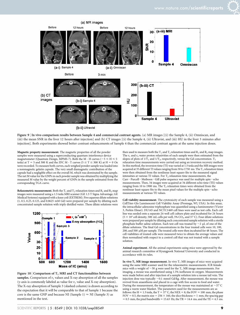
We performed additional in vivo CT and MR imaging experi-ments to compare one of our samples (i.e., Sample 4) with commer-cial MRI (i.e., Omniscan) and CT (i.e., Ultravist) contrast agents atthe same injection doses. In vivo MR coronal images of a rat obtainedwith the Sample 4 and Omniscan at 12 hours after intravenousinjection into its tail are shown in Fig. 9a(i) and (ii), respectively.Compared to Omniscan, the Sample 4 showed stronger signalenhancements in the liver. This can be clearly seen in the mean signalto noise ratio (SNR) plot in Fig. 9a(iii). In a similar way, in vivo CTaxial images of a rat obtained with the Sample 4 and Ultravist at3 minutes after intravenous injection into its tail are shown inFig. 9b(i) and (ii), respectively. Compared to Ultravist, the Sample4 showed stronger signal enhancements in the liver. This can beclearly seen in the mean signal intensity plot in Fig. 9b(iii). Theinjection doses were ,0.64 mmol Gd/kg for MR image measure-ments and ,0.53 mmol Gd/kg for CT image measurements.Sprague Dawley (SD) rats (4 weeks, male) were used.
Comparison between samples. Based on r1 values and X-rayabsorption powers, the in vitro T1 MRI and CT capabilityevaluations of all the samples are summarized in Fig. 10. As shownin Fig. 10, it seems that the combined capabilities of T1 MRI and CTare roughly in the order of Sample 1 < Sample 3 . Sample 2 <Sample 4. Here, the X-ray absorption of Sample 3 (slashed column) isdrawn according to the expectation that it will be comparable to thatof Sample 1 because the core is the same GNP and because NI(Sample 1) < NI (Sample 3) (Table 1). Overall, GNPs with a
smaller (i.e., less massive) IC coating showed larger r1 values andhigher X-ray absorption. This is because more water molecules canaccess the core GNP for a smaller IC coating, providing the larger r1
values81, and because GNPs with a smaller IC coating had larger NIvalues (Table 1), giving higher X-ray absorption, which explains theobserved r1 values and X-ray absorption results in Fig. 10. However,all the samples showed larger r1 values than commercial T1 MRIcontrast agents because of the GNPs as they contained, and higherX-ray absorption than commercial iodine contrast agents because ofboth the Gd and I as they contained. Therefore, all the samplesshould be potential dual imaging agents in T1 MRI and CT.
DiscussionGd is the only element that possesses such diverse and remarkableproperties, which are useful for theragnosis for cancers. Therefore,GNPs with the large amount of Gd per GNP will be a powerfultheragnostic agent for cancers (Fig. 1)27,28,61. The only shortcomingof Gd is its toxicity66. Therefore, GNPs should be coated with water-soluble and biocompatible ligands. Note that this theragnosis mightbe difficult using the conventional molecular Gd-chelates, because oftheir low Gd concentrations that could be delivered to cancers60.
This study reports the dual imaging capability of GNPs in T1 MRIand CT. To this end, four IC-GNP samples were synthesized. Fourcommercial iodine contrast agents were used as surface coatingligands on GNPs (davg 5 ,2.0 nm) to enhance the CT functional-ities of the nanoparticles using iodines in the ICs, as well as to makethem water-soluble and biocompatible. To evaluate the dual imagingcapability of GNPs, the r1 values and X-ray absorption of all thesamples were measured, and in vivo T1 MR and CT images of micewere finally obtained.
Overall, GNPs with a smaller (i.e., less massive) IC coating showedlarger r1 values and higher X-ray absorption (Fig. 10). This is becausemore water molecules can access the core GNP for a smaller ICcoating, providing the larger r1 values81, and because GNPs with asmaller IC coating had larger NI values (Table 1), giving higher X-rayabsorption. However, all the samples showed larger r1 values thancommercial T1 MRI contrast agents, and higher X-ray absorptionthan commercial iodine contrast agents. Therefore, all the samplesshould be potential dual imaging agents in T1 MRI and CT.
The dual imaging capability of GNPs was finally confirmed by invivo T1 MR and CT images. That is, positive (or brighter) contrastenhancements in both T1 MR and CT images were observed in miceafter intravenous injection (Fig. 8). Finally, in vivo comparisonsbetween one of IC-GNP samples and commercial MRI and CT con-trast agents were made. More enhanced contrasts in both MR and CTimages at the same injection doses were observed, showing thesuperiority of IC-GNPs to the commercial contrast agents (Fig. 9).
In summary, owing to unique magnetic and X-ray absorptionproperties of Gd, and a dense population of Gd per GNP, GNPsshowed an outstanding dual imaging capability in T1 MRI and CTwithout additional functionalization, which is better than therespective commercial contrast agents. This, when combined withthe NCT property of GNPs, will make GNPs a potential theragnosticagent for cancers, which will be investigated in the future.
MethodsChemicals. All the chemicals such as GdCl3?xH2O (.99.9%), NaOH (.99.9%),triethylene glycol (.99%), 5-amino-2,4,6-triiodoisophthalic acid (.95%),iodipamide (.99%), diatrizoic acid (.99%), iodixanol [60% (w/v) in water], anddimethyl sulfoxide (DMSO) (.99.5%) were purchased from Sigma-Aldrich and usedas-received. Triply distilled water was used for both washing the nanoparticles andpreparing the aqueous sample solutions.
One-pot synthesis of IC-GNP samples. Four IC-GNP samples were prepared bycoating four different types of ICs on GNPs. The ICs used were 5-amino-2,4,6-triiodoisophthalic acid, iodipamide, diatrizoic acid, and iodixanol, which are allcommercial CT contrast agents (Table 1 and Fig. 4).
Figure 7 | In vitro cytotoxicity results. Normalized cell viabilities
of four sample solutions in (a) DU145 and (b) NCTC1469 cell lines are
plotted as a function of the Gd concentration, showing no toxicity up to
500 mM Gd.
www.nature.com/scientificreports
SCIENTIFIC REPORTS | 5 : 8549 | DOI: 10.1038/srep08549 7

The IC-GNP samples were synthesized in one-pot using the procedure shown inFig. 11. Three separate solutions were prepared: (i) a precursor solution made of5 mmol of GdCl3?xH2O in 25 mL of triethylene glycol, (ii) a NaOH solution made of15 mmol of NaOH in 10 mL of triethylene glycol, and (iii) an IC solution made of5 mmol of IC in 10 mL of triethylene glycol (in the case of iodipamide, five drops ofDMSO were also added to the solution to completely dissolve the iodipamide). Theprecursor solution was heated to 60uC with magnetic stirring under atmosphericconditions until the precursor was completely dissolved in the solvent. The NaOHsolution was then added to the precursor solution. The mixed solution wasmagnetically stirred at 180uC for 4 hours. For surface coating, the solution tem-perature was then lowered to 60uC and an IC solution was added slowly to theabove solution. The temperature of the solution was again raised to 110uC, andthe solution was magnetically stirred for an additional 12 hours. To wash the IC-GNP samples with triply distilled water, the solution was then cooled to roomtemperature and transferred to a 1 L beaker containing 500 mL of triply distilledwater. It was then magnetically stirred for 10 minutes and stored for a week to letthe IC-GNP samples settle to the bottom of the beaker. The clear supernatant wasdecanted and the remaining sample was again diluted with 500 mL of triplydistilled water. This washing process was repeated three times. A half volume ofeach sample was dried in air to obtain powder samples for various characteriza-tions, and the remaining half volume was diluted with triply distilled water toobtain solution samples.
Measurements of particle diameter, hydrodynamic diameter, and crystalstructure. The particle diameters of the IC-GNP samples were measured using anHRTEM (FEI, Titan G2 ChemiSTEM CS Probe) operating at an acceleration voltageof 200 kV. For the measurements, one drop of each sample dispersed in ethanol wasdropped onto a carbon film supported by a 200 mesh copper grid (PELCO No.160,TED PELLA, INC.) placed on a filter paper using a micropipette (Eppendorf, 2–20 mL). The copper grid with the sample was left in air to dry for an hour at roomtemperature. The copper grid with the sample was then mounted inside the HRTEMfor measurement.
The Gd concentration of each sample solution was determined using an induc-tively coupled plasma atomic emission spectrometer (Thermo Jarrell Ash Co., IRIS/AP). All the samples were pre-treated with acids to completely dissolve the nano-particles in solution before measurement.
The hydrodynamic diameters of the IC-GNP samples dispersed in triply distilledwater were measured using a DLS particle size analyzer (UPA-150, Microtrac). Thesample solution concentration was , 0.05 mM Gd.
The crystal structure of the IC-GNP powder samples before and after TGA analysiswas measured using a powder XRD spectrometer (Philips, X-PERT PRO MRD) withunfiltered CuKa (l 5 1.54184 A) radiation. The scanning step and scan range in 2hwere 0.033u and 15–100u, respectively.
Surface coating analysis. The surface coating of GNPs with ICs was investigatedusing an FT-IR absorption spectrometer (Mattson Instruments, Inc., Galaxy 7020A).For the measurements, powder samples were dried on a hot plate at ,40uC for a weekto remove moisture from them. Pellets of dried powder samples in KBr wereprepared, and FT-IR absorption spectra were recorded between 400 and 4000 cm21.
The amount of the IC coated on the GNP surface was estimated using a TGAinstrument (TA Instruments, SDT-Q 600). Because organic compounds burn outbelow 400uC, TGA curves for each powder sample were scanned between roomtemperature and 700uC under air flow. The amount of surface coating for each samplewas estimated from the mass drop in its TGA curve after an initial mass drop betweenroom temperature and ,105uC due to water desorption was subtracted.
The elemental analyses of surface coated ICs on GNP surfaces were carried outusing both the EA (ThermoFisher, Flash 2000) and XPS (ULVAC-PHI, QuanteraSXM). Powder samples were used for both measurements. For XPS measure-ments, powder samples were loaded onto carbon tapes and the spectra werescanned between 0 and 1200 eV in electron binding energy (EBE) with theaccumulation time of 30 to 50 minutes. The EA was used to measure the C, H, O,and N in weight percents, whereas the XPS was used to measure the C, O, N, I,and Gd in atomic percents.
Figure 8 | In vivo images of a mouse. (a) T1 MR images of a mouse liver (labeled L), (b) kidneys (labeled K) and aorta (labeled A) at 1.5 tesla
MR field before and after intravenous injection of Sample 1 into a mouse tail, (c) plots of SNR of ROI in the liver and the cortex and medulla of kidney
[positions are labeled with small dotted circles in (a) and (b)] as a function of the time after intravenous injection, (d) in vivo CT images of a
mouse bladder (labeled B) before and after intravenous injection of Sample 1 into a mouse tail at an X-ray source voltage of 70 kV, and (e) a plot of X-ray
absorption value of ROI in the bladder [position is labeled with a small dotted circle in (d)] as a function of the time after intravenous injection.
www.nature.com/scientificreports
SCIENTIFIC REPORTS | 5 : 8549 | DOI: 10.1038/srep08549 8
Magnetic property measurement. The magnetic properties of all the powdersamples were measured using a superconducting quantum interference devicemagnetometer (Quantum Design, MPMS-7). Both the M - H curves (25 # H # 5tesla) at T 5 5 and 300 K and the ZFC M - T curves (5 # T # 300 K) at H 5 0 Oewere recorded. To measure both curves, each weighed powder sample was loaded intoa nonmagnetic gelatin capsule. The very small diamagnetic contribution of thecapsule had a negligible effect on the overall M, which was dominated by the sample.The net M value for the GNPs in each powder sample was obtained by multiplying themeasured M value by the weight percent of GNPs in the sample estimated from thecorresponding TGA curve.
Relaxometric measurement. Both the T1 and T2 relaxation times and R1 and R2 mapimages were measured using a 1.5 tesla MRI scanner (GE 1.5 T Signa Advantage, GEMedical Systems) equipped with a knee coil (EXTREM). Five aqueous dilute solutions(1, 0.5, 0.25, 0.125, and 0.0625 mM Gd) were prepared per sample by diluting eachconcentrated sample solution with triply distilled water. These dilute solutions were
then used to measure both the T1 and T2 relaxation times and R1 and R2 map images.The r1 and r2 water proton relaxivities of each sample were then estimated from theslopes of plots of 1/T1 and 1/T2, respectively, versus the Gd concentration. T1
relaxation time measurements were carried out using an inversion recovery method.In this method, the inversion time (TI) was varied at 1.5 tesla and the MR images wereacquired at 35 different TI values ranging from 50 to 1750 ms. The T1 relaxation timeswere then obtained from the nonlinear least-square fits to the measured signalintensities at various TI values. For T2 relaxation time measurements, theCarr2Purcell2Meiboon2Gill pulse sequence was used for multiple spin2echomeasurements. Then, 34 images were acquired at 34 different echo time (TE) valuesranging from 10 to 1900 ms. The T2 relaxation times were obtained from thenonlinear least-square fits to the mean pixel values for the multiple spin2echomeasurements at various TE values.
Cell viability measurement. The cytotoxicity of each sample was measured using aCellTiter-Glo Luminescent Cell Viability Assay (Promega, WI, USA). In this assay,the intracellular adenosine triphosphate was quantified using a luminometer (Victor3, Perkin Elmer). DU145 and NCTC1469 cell lines were used as test cells. Each cellline was seeded onto a separate 24-well cell culture plate and incubated for 24 hours(5 3 104 cell density, 500 mL cells per well, 5% CO2, and 37uC). Four dilute solutionswere prepared per sample by diluting each concentrated sample solution with a sterilephosphate buffer saline solution. Each test cell was treated by ,2 mL of one of thedilute solutions. The final Gd concentrations in the four treated cells were 10, 100,200, and 500 mM per sample. The treated cells were then incubated for 48 hours. Thecell viabilities of treated cells were measured twice to obtain the average values andthen normalized with respect to a control cell that was not treated with a samplesolution.
Animal experiment. All the animal experiments using mice were approved by theanimal research committee of Kyungpook National University and conducted inaccordance with its rules.
In vivo T1 MR image measurement. In vivo T1 MR images of mice were acquiredusing the same MRI scanner used for the relaxometric measurements. ICR femalemice with a weight of ,30 g were used for the T1 MR image measurements. Forimaging, a mouse was anesthetized using 1.5% isoflurane in oxygen. Measurementswere made before and after injection of a sample solution into a mouse tail vein. Theinjection dose was typically ,0.1 mmol Gd/kg. After measurement, the mouse wasrevived from anaesthesia and placed in a cage with free access to food and water.During the measurement, the temperature of the mouse was maintained at ,37uCusing a warm water blanket. The parameters used for the measurements are asfollows: the H 5 1.5 tesla, the T 5 37uC, the NEX 5 8, the FOV 5 100 mm, the phaseFOV 5 0.5, the matrix size 5 256 3 160, the slice thickness 5 1 mm, the spacing gap5 0.5 mm, the pixel bandwidth 5 15.63 Hz, the TR 5 14.4 ms, and the TE 5 4.3 ms.
Figure 9 | In vivo comparison results between Sample 4 and commercial contrast agents. (a) MR images [(i) the Sample 4, (ii) Omniscan, and
(iii) the mean SNR in the liver 12 hours after injection] and (b) CT images [(i) the Sample 4, (ii) Ultravist, and (iii) HU in the liver 3 minutes after
injection]. Both experiments showed better contrast enhancements of Sample 4 than the commercial contrast agents at the same injection doses.
Figure 10 | Comparison of T1 MRI and CT functionalities betweensamples. Comparison of r1 values and X-ray absorption of all the samples
(y-axis is commonly labeled as value for r1 value and X-ray absorption).
The X-ray absorption of Sample 3 (slashed column) is drawn according to
the expectation that it will be comparable to that of Sample 1 because the
core is the same GNP and because NI (Sample 1) < NI (Sample 3) as
mentioned in the text.
www.nature.com/scientificreports
SCIENTIFIC REPORTS | 5 : 8549 | DOI: 10.1038/srep08549 9

Phantom image and X-ray absorption measurements. X-ray phantom images wereacquired using a micro-CT scanner (Siemens, Inveon). Four dilute solutions (20, 50,80, and 100 mM Gd) were prepared per sample by diluting each concentrated samplesolution with triply distilled water. A phantom image of water served as a referencewith 0.0 HU, and those of the commercial contrast agents Ultravist (20, 50, 80, and100 mM I) and Omniscan (20, 50, 80, and 100 mM Gd) were also measured forcomparison. The X-ray absorption of each dilute solution was estimated in HU withrespect to water. The parameters used for the measurements are as follows: the X-raysource current 5 400 mA, the X-ray source voltage 5 70 kV, the imaging time perframe 5 200 ms, and the reconstructed image size 5 512 3 512.
In vivo CT image measurement. In vivo CT images of mice were acquired using thesame micro-CT scanner used for the phantom image measurements. ICR female micewith a weight of ,30 g were used for the measurements. The injection dose wastypically ,0.53 mmol Gd/kg. For imaging, a mouse was anesthetized using 1.5%isoflurane in oxygen. Measurements were made before and after injection of a samplesolution into a mouse tail vein. After measurement, the mouse was revived fromanaesthesia and placed in a cage with free access to food and water. The parametersused for measurements are as follows: the X-ray source current 5 400 mA, the X-raysource voltage 5 70 kV, the imaging time per frame 5 200 ms, and the reconstructedimage size 5 512 3 512.
1. Swierczewska, M., Liu, G., Lee, S. & Chen, X. High-sensitivity nanosensors forbiomarker detection. Chem. Soc. Rev. 41, 2641–2655 (2012).
2. Gao, J. & Xu, B. Applications of nanomaterials inside cells. Nano Today 4, 37–51(2009).
3. Rosi, N. L. & Mirkin, C. A. Nanostructures in biodiagnostics. Chem. Rev. 105,1547–1562 (2005).
4. Kim, B. Y. S., Rutka, J. T. & Chan, W. C. W. Nanomedicine. N. Engl. J. Med. 363,2434–2443 (2010).
5. Riehemann, K. et al. Nanomedicine-challenge and perspectives. Angew. Chem.Int. Ed. 48, 872–897 (2009).
6. Dreaden, E. C., Alkilany, A. M., Huang, X., Murphy, C. J. & El-Sayed, M. A. Thegolden age: gold nanoparticles for biomedicine. Chem. Soc. Rev. 41, 2740–2779(2012).
7. Yoo, D., Lee, J.-H., Shin, T.-H. & Cheon, J. Theranostic magnetic nanoparticles.Acc. Chem. Res. 44, 863–874 (2011).
8. Lee, J. E., Lee, N., Kim, T., Kim, J. & Hyeon, T. Multifunctional mesoporous silicananocomposite nanoparticles for theranostic applications. Acc. Chem. Res. 44,893–902 (2011).
9. Xu, W. et al. Paramagnetic nanoparticle T1 and T2 MRI contrast agents. Phys.Chem. Chem. Phys. 14, 12687–12700 (2012).
10. Lee, G. H., Chang, Y. & Kim, T.-J. Blood-pool and targeting MRI contrast agents:from Gd-chelates to Gd-nanoparticles. Eur. J. Inorg. Chem. 1924–1933 (2012);DOI: 10.1002/ejic.201101137 (2012).
11. Kim, T. J., Chae, K. S., Chang, Y. & Lee, G. H. Gadolinium oxide nanoparticles aspotential multimodal imaging and therapeutic agents. Curr. Top. Med. Chem. 13,422–433 (2013).
12. Salata, O. V. Applications of nanoparticles in biology and medicine.J. Nanobiotechnology 2, 3 (2004); DOI: 10.1186/1477-3155-2-3 (2004).
13. Lodhia, J., Mandarano, G., Ferris, N. J., Eu, P. & Cowell, S. F. Development and useof iron oxide nanoparticles (Part 1): synthesis of iron oxide nanoparticles for MRI.Biomed. Imaging Interv. J. 6, e12 (2010); DOI: 10.2349/biij.6.2.e12 (2010).
14. Mandarano, G. et al. Development and use of iron oxide nanoparticles (Part 2):the application of iron oxide contrast agents in MRI. Biomed. Imaging Interv. J. 6,e13 (2010); DOI: 10.2349/biij.6.2.e13 (2010).
15. Pankhurst, Q. A., Thanh, N. K. T., Jones, S. K. & Dobson, J. Progress inapplications of magnetic nanoparticles in biomedicine. J. Phys. D: Appl. Phys. 42,224001 (2009); DOI: 10.1088/0022-3727/42/22/224001 (2009).
16. Roca, A. G. et al. Progress in the preparation of magnetic nanoparticles forapplications in biomedicine. J. Phys. D: Appl. Phys. 42, 224002 (2009); DOI:10.1088/0022-3727/42/22/224002 (2009).
17. Berry, C. C. Progress in functionalization of magnetic nanoparticles forapplications in biomedicine. J. Phys. D: Appl. Phys. 42, 224003 (2009); DOI:10.1088/0022-3727/42/22/224003 (2009).
18. Lee, D.-E. et al. Multifunctional nanoparticles for multimodal imaging andtheragnosis. Chem. Soc. Rev. 41, 2656–2672 (2012).
19. Xie, J., Lee, S. & Chen, X. Nanoparticle-based theranostic agents. Adv. Drug. Deliv.Rev. 62, 1064–1079 (2010).
20. Ho, Y.-P. & Leong, K. W. Quantum dot-based theranostics. Nanoscale 2, 60–68(2010).
21. Kim, J., Piao, Y. & Hyeon, T. Multifunctional nanostructured materials formultimodal imaging, and simultaneous imaging and therapy. Chem. Soc. Rev. 38,372–390 (2009).
22. Irvine, D. J. Drug delivery: one nanoparticle, one kill. Nat. Mater. 10, 342–343(2011).
23. Fan, Y. et al. Luminescent and mesoporous europium-doped bioactive glasses(MBG) as a drug carrier. J. Phys. Chem. C 113, 7826–7830 (2009).
24. Shilo, M., Reuveni, T., Motiei, M. & Popovtzer, R. Nanoparticles as computedtomography contrast agents: current status and future perspectives.Nanomedicine (Lond) 7, 257–269 (2012).
25. Wang, H. et al. Computed tomography imaging of cancer cells using acetylateddendrimer-entrapped gold nanoparticles. Biomaterials 32, 2979–2988 (2011).
26. Hainfeld, J. F., Slatkin, D. N., Focella, T. M. & Smilowitz, H. M. Goldnanoparticles: a new X-ray contrast agent. Br. J. Radiol. 79, 248–253 (2006).
27. Stefanakis, D. & Ghanotakis, D. F. Synthesis and characterization of gadoliniumnanostructured materials with potential applications in magnetic resonanceimaging, neutron-capture therapy and targeted drug delivery. J. Nanopart. Res.12, 1285–1297 (2010).
28. McDonald, M. A. & Watkin, K. L. Small particulate gadolinium oxide andgadolinium albumin microspheres as multimodal contrast and therapeuticagents. Invest. Radiol. 38, 305–310 (2003).
29. Watkin, K. L. & McDonald, M. A. Multi-modal contrast agents: a first step. Acad.Radiol. 9, S285–S289 (2002).
30. Lauffer, R. B. Paramagnetic metal complexes as water proton relaxation agents forNMR imaging: theory and design. Chem. Rev. 87, 901–927 (1987).
31. Caravan, P., Ellison, J. J., McMurry, T. J. & Lauffer, R. B. Gadolinium(III) chelatesas MRI contrast agents: structure, dynamics, and applications. Chem. Rev. 99,2293–2352 (1999).
32. Lee, E. J. et al. D-glucuronic acid coated Gd(IO3)3?2H2O nanomaterial as apotential T1 MRI-CT dual contrast agent. Eur. J. Inorg. Chem. 2858–2866 (2013);DOI: 10.1002/ejic.201201481 (2013).
33. Kawano, T., Ishijima, H., Nakajima, T., Aoki, J. & Endo, K. Gd-DTPA: a possiblealternative contrast agent for use in CT during intraarterial administration.J. Comput. Assist. Tomogr. 23, 939–940 (1999).
34. Cheung, E. N. M. et al. Polymer-stabilized lanthanide fluoride nanoparticleaggregates as contrast agents for magnetic resonance imaging and computedtomography. Chem. Mater. 22, 4728–4739 (2010).
35. Hubbell, J. H. & Seltzer, S. M. Tables of X-Ray Mass Attenuation Coefficients andMass Energy-Absorption Coefficients from 1 keV to 20 MeV for Elements Z 5 1 to92 and 48 Additional Substances of Dosimetric Interest, online available at http://www.nist.gov/pml/data/xraycoef (NIST, Gaithersburg, 1996).
36. Weast, R. C., Astle, M. J. & Beyer, W. H. CRC Handbook of Chemistry and Physics[Weast, R. C. (ed.)] [B235–B319] (CRC Press, Boca Raton, 1984–1985).
37. Mughabghab, S. F. Thermal Neutron Capture Cross Sections: Resonance Integralsand g-Factors (IAEA, Vienna, 2003).
38. Kim, H., Achermann, M., Balet, L. P., Hollingsworth, J. A. & Klimov, V. I.Synthesis and characterization of Co/CdSe core/shell nanocomposites:bifunctional magnetic-optical nanocrystals. J. Am. Chem. Soc. 127, 544–546(2005).
39. Gu, H., Zheng, R., Zhang, X. & Xu, B. Facile one-pot synthesis of bifunctionalheterodimers of nanoparticles: a conjugate of quantum dot and magneticnanoparticles. J. Am. Chem. Soc. 126, 5664–5665 (2004).
40. Bridot, J.-L. et al. Hybrid gadolinium oxide nanoparticles: multimodal contrastagents for in vivo imaging. J. Am. Chem. Soc. 129, 5076–5084 (2007).
41. Hashemi, R. H., Bradley, W. G. & Lisanti, C. J. MRI The Basics (LippincottWilliams & Wilkins, New York, 2004).
42. Rudin, M. Molecular Imaging: Basic Principles and Applications in BiomedicalResearch (Imperial College Press, London, 2005).
43. Weissleder, R. & Mahmood, U. Molecular imaging. Radiology 219, 316–333(2001).
44. Herman, G. T. Fundamentals of Computerized Tomography: ImageReconstruction from Projection (Springer, New York, 2009).
45. Paeng, J. C. & Lee, D. S. Multimodal molecular imaging in vivo. Open Nucl. Med. J.2, 145–152 (2010).
Figure 11 | One-pot synthesis. One-pot synthesis procedure for four IC-GNP samples.
www.nature.com/scientificreports
SCIENTIFIC REPORTS | 5 : 8549 | DOI: 10.1038/srep08549 10

46. Grainger, R. G. Intravascular contrast media-the past, the present and the future.Br. J. Radiol. 55, 1–18 (1982).
47. Lusic, H. & Grinstaff, M. W. X-ray-computed tomography contrast agents. Chem.Rev. 113, 1641–1666 (2013).
48. Yu, S.-B. & Watson, A. D. Metal-based X-ray contrast media. Chem. Rev. 99,2353–2377 (1999).
49. Wharton, T. & Wilson, L. J. Highly-iodinated fullerene as a contrast agent for X-ray imaging. Bioorg. Med. Chem. 10, 3545–3554 (2002).
50. Nelson, R. C., Chezmar, J. L., Peterson, J. E. & Bernardino, M. E. Contrast-enhanced CT of the liver and spleen: comparison of ionic and nonionic contrastagents. AJR 153, 973–976 (1989).
51. Zwicker, C., Hering, M. & Langer, R. Computed tomography with iodine-freecontrast media. Eur. Radiol. 7, 1123–1126 (1997).
52. Bloem, J. L. & Wondergem, J. Gd-DTPA as a contrast agent in CT. Radiology 171,578–579 (1989).
53. Quinn, A. D., O’Hare, N. J., Wallis, F. J. & Wilson, G. F. Gd-DTPA: an alternativecontrast medium for CT. J. Comput. Assist. Tomogr. 18, 634–636 (1994).
54. Gibson, R. J., Meanock, C. I., Torrie, E. P. H. & Walker, T. M. An assessment ofGd-DTPA as a CT contrast agent in the renal tract. Clin. Radiol. 47, 278–279(1993).
55. Seeliger, E., Sendeski, M., Rihal, C. S. & Persson, P. B. Contrast-induced kidneyinjury: mechanisms, risk factors, and prevention. Eur. Heart. J. 33, 2007–2015(2012).
56. Barth, R. F. et al. Current status of boron neutron capture therapy of high gradegliomas and recurrent head and neck cancer. Radiat. Oncol. 7, 146 (2012); DOI:10.1186/1748-717X-7-146 (2012).
57. Barth, R. F., Soloway, A. H. & Brugger, R. M. Boron neutron capture therapy ofbrain tumors: past history, current status, and future potential. Cancer Invest. 14,534–550 (1996).
58. Barth, R. F. et al. Boron neutron capture therapy of brain tumors: an emergingtherapeutic modality. Neurosurgery 44, 433–450 (1999).
59. Barth, R. F., Coderre, J. A., Vicente, M. G. & Blue, T. E. Boron neutron capturetherapy of cancer: current status and future prospects. Clin. Cancer Res. 11,3987–4002 (2005).
60. De Stasio, G. et al. Are gadolinium contrast agents suitable for gadolinium neutroncapture therapy? Neurol. Res. 27, 387–398 (2005).
61. Bridot, J.-L. et al. Hybrid gadolinium oxide nanoparticles combining imaging andtherapy. J. Mater. Chem. 19, 2328–2335 (2009).
62. Masiakowski, J. T., Horton, J. L. & Peters, L. J. Gadolinium neutron capturetherapy for brain tumors: a computer study. Med. Phys. 19, 1277–1284 (1992).
63. Soderlind, F., Pedersen, H., Petoral Jr, R. M., Kall, P.-O. & Uvdal, K. Synthesis andcharacterization of Gd2O3 nanocrystals functionalized by organic acids. J. ColloidInterface Sci. 288, 140–148 (2005).
64. Kattel, K. et al. A facile synthesis, in vitro and in vivo MR studies of D-glucuronicacid-coated ultrasmall Ln2O3 (Ln 5 Eu, Gd, Dy, Ho, and Er) nanoparticles as anew potential MRI contrast agent. ACS Appl. Mater. Interfaces 3, 3325–3334(2011).
65. Gd2O3, 1977 JCPDS-International Centre for Diffraction Data, card no. 43–1014,a 5 10.813 A.
66. Thomsen, H. S. Nephrogenic systemic fibrosis: a serious late adverse reaction togadodiamide. Eur. Radiol. 16, 2619–2621 (2006).
67. Corbierre, M. K., Cameron, N. S. & Lennox, R. B. Polymer-stabilized goldnanoparticles with high grafting densities. Langmuir 20, 2867–2873 (2004).
68. Gd2O3 bulk density, Aldrich Catalog, 2005– 2006, p. 1260.69. Pearson, R. G. Hard and soft acids and bases. J. Am. Chem. Soc. 85, 3533–3539
(1963).70. Pearson, R. G. Hard and soft acids and bases, HSAB, part 1: fundamental
principles. J. Chem. Educ. 45, 581–587 (1968).71. Pearson, R. G. Hard and soft acids and bases, HSAB, part II: underlying theories.
J. Chem. Educ. 45, 643–648 (1968).
72. Duckworth, O. W. & Martin, S. T. Surface complexation and dissolution ofhematite by C1-C6 dicarboxylic acids at pH 5 5.0. Geochim. Cosmochim. Acta 65,4289–4301 (2001).
73. Hug, S. J. & Bahnemann, D. Infrared spectra of oxalate, malonate and succinateadsorbed on the aqueous surface of rutile, anatase and lepidocrocite measuredwith in situ ATR-FTIR. J. Electron Spectrosc. Relat. Phenom. 150, 208–219 (2006).
74. Hug, S. J. & Sulzberger, B. In situ Fourier transform infrared spectroscopicevidence for the formation of several different surface complexes of oxalate onTiO2 in the aqueous phase. Langmuir 10, 3587–3597 (1994).
75. Mendive, C. B., Bredow, T., Blesa, M. A. & Bahnemann, D. W. ATR-FTIRmeasurements and quantum chemical calculations concerning the adsorptionand photoreaction of oxalic acid on TiO2. Phys. Chem. Chem. Phys. 8, 3232–3247(2006).
76. Moon, R. M. & Koehler, W. C. Magnetic properties of Gd2O3. Phys. Rev. B 11,1609–1622 (1975).
77. Lal, H. B., Pratap, V. & Kumar, A. Magnetic susceptibility of heavy rare-earthsesquioxides. Pramana 10, 409–412 (1978).
78. Wolf, W. P., Meissner, H. & Catanese, C. A. Magnetic properties of rare earthhydroxides. J. Appl. Phys. 39, 1134–1136 (1968).
79. Arajs, S. & Colvin, R. V. Magnetic susceptibility of gadolinium and dysprosiumsesquioxides at elevated temperatures. J. Appl. Phys. 33, 2517–2519 (1962).
80. Cullity, B. D. Introduction to Magnetic Materials [190] (Addison-WesleyPublishing Company, Reading, 1972).
81. Kim, C. R. et al. Ligand-size dependent water proton relaxivities in ultrasmallgadolinium oxide nanoparticles and in vivo T1 MR images in a 1.5 T MR field.Phys. Chem. Chem. Phys. 16, 19866–19873 (2014).
82. Willekens, I. et al. Time-course of contrast enhancement in spleen and liver withExia 160, Fenestra LC, and VC. Mol. Imaging Biol. 11, 128–135 (2009).
AcknowledgmentsThis study was supported by the Basic Science Research Program (Grant No. 2014-005837to YC and 2013R1A1A4A03004511 to GHL) and the Basic Research Laboratory (BRL)Program (2013R1A4A1069507) of the National Research Foundation funded by theMinistry of Education, Science, and Technology. The authors thank the Korea Basic ScienceInstitute for the use of their HRTEM and XRD equipment.
Author contributionsM.W.A. synthesized and characterized the samples. W.X. and S.J.K. characterized thesamples. J.S.B. and Y.C. measured the relaxivities, and MR and CT images. J.E.B. and K.S.C.measured the cellular toxicities. J.A.P. obtained the X-ray phantom and CT images. T.J.K.and G.H.L. led the project and G.H.L. wrote the paper.
Additional informationSupplementary information accompanies this paper at http://www.nature.com/scientificreports
Competing financial interests: The authors declare no competing financial interests.
How to cite this article: Ahmad, M.W. et al. Potential dual imaging nanoparticle: Gd2O3
nanoparticle. Sci. Rep. 5, 8549; DOI:10.1038/srep08549 (2015).
This work is licensed under a Creative Commons Attribution 4.0 InternationalLicense. The images or other third party material in this article are included in thearticle’s Creative Commons license, unless indicated otherwise in the credit line; ifthe material is not included under the Creative Commons license, users will needto obtain permission from the license holder in order to reproduce the material. Toview a copy of this license, visit http://creativecommons.org/licenses/by/4.0/
www.nature.com/scientificreports
SCIENTIFIC REPORTS | 5 : 8549 | DOI: 10.1038/srep08549 11

1
Supplementary Information
Title: Potential dual imaging nanoparticle: Gd2O3 nanoparticle
Authors: Md. Wasi Ahmad, Wenlong Xu, Sung June Kim, Jong Su Baeck, Yongmin Chang, Ji Eun
Bae, Kwon Seok Chae, Ji Ae Park, Tae Jeong Kim & Gang Ho Lee
(1) XRD patterns before and after TGA analysis
The XRD patterns of the as-prepared powder samples and after TGA analysis are shown in Fig. S1.
Very broad XRD patterns of the as-prepared powder samples are likely because of their ultrasmall
particle diameters1. After TGA analysis up to ~ 700 oC, however, sharp peaks corresponding to (211),
(222), (400), (440), and (622) of cubic Gd2O3, appeared as shown at the top in the XRD patterns. The
estimated cell constant (a) of the TGA-analyzed powder sample is 10.81 Å, which is consistent with
the reported value (= 10.813 Å) of cubic Gd2O3 (card no. 43-1014, PCPDFWIN)2. The measured
peak positions and cell constant are provided in Table S1.
20 40 60 80 100
(211) (622)(440)(400) After TGA
Sample 4
Sample 3
Sample 2
Inte
nsity
(Arb
. Uni
ts)
2θ (o)
Sample 1
(222)
Figure S1. XRD patterns of the as-prepared powder samples and after TGA analysis.
2
Table S1. Peak assignment with Miller index (hkl) and cell constant (a).
hkl 2θ (o)
211 20.03 222 28.55 400 33.12 440 47.50 622 56.44 a = 10.81 Å
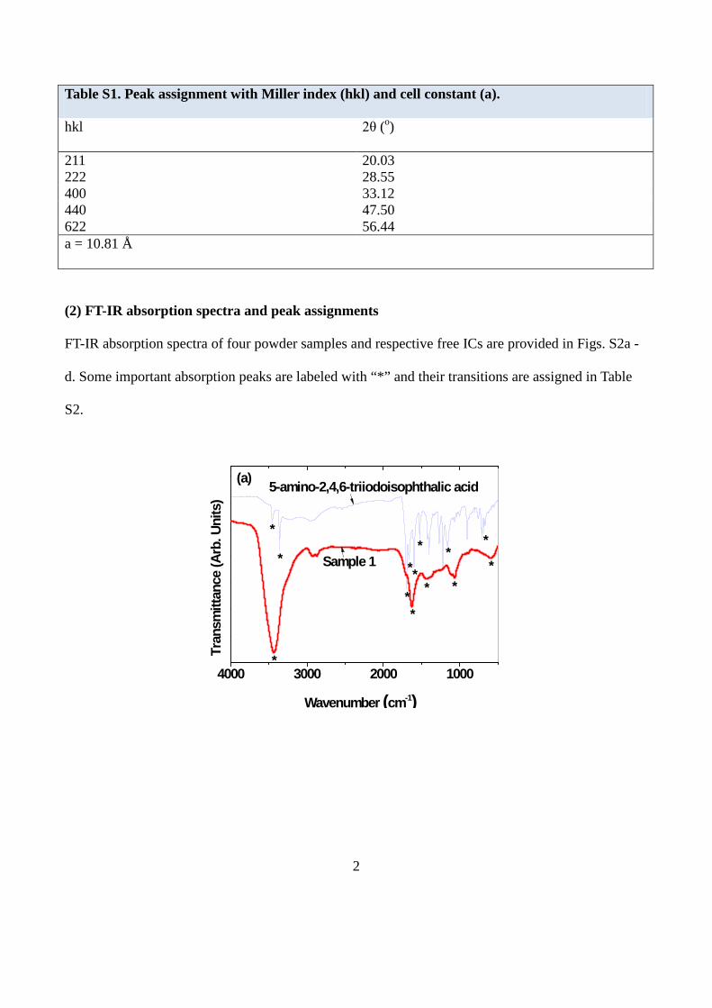
(2) FT-IR absorption spectra and peak assignments
FT-IR absorption spectra of four powder samples and respective free ICs are provided in Figs. S2a -
d. Some important absorption peaks are labeled with “*” and their transitions are assigned in Table
S2.
4000 3000 2000 1000
*
**
**
*
**
**
*
*
Sample 1
Tran
smitt
ance
(Arb
. Uni
ts)
Wavenumber (cm-1)
5-amino-2,4,6-triiodoisophthalic acid(a)
*

3
4000 3000 2000 1000
*
**
***
***
*
Sample 2
Tran
smitt
ance
(Arb
. Uni
ts)
Wavenumber (cm-1)
Iodipamide(b)
*
4000 3000 2000 1000
*
*
**
**
*
* ***
****
**
*
Sample 3
Tran
smitt
ance
(Arb
. Uni
ts)
Wavenumber (cm-1)
Diatrizoic acid(c)
*

4
4000 3000 2000 1000
*
**
*
*****
*
**
Tran
smitt
ance
(Arb
. Uni
ts)
Wavenumber (cm-1)
(d) Iodixanol
Sample 4
*
Figure S2. FT-IR absorption spectra of four powder samples and respective free ICs.
Table S2. Assignment of vibrational absorption peaks.
Sample IC-GNP Free IC
Peak (cm-1)
Assignment Peak (cm-1)
Assignment
Sample 1 3432 1630 1440 1069 590
(OH)S (COOH)AS (COOH)SS (CO)S (GdO)S
3459 3360 1698 1662 1595 1523 1159 686
(NH2)AS (NH2)S (COOH)AS (NH2)B (C=C)S (COOH)SS (CO)S (CI)S
Sample 2 3436 1632 1511 1381 1070 584
(OH)S (COOH)AS / (C=O)S (NH)B / (C=C)S (COOH)SS (CO)S (GdO)S
3436 1697 1619 1539 591
(OH)S (COOH)AS (NH)B / (C=O)S (COOH)SS (CI)S
Sample 3 3417 2920 2875 1639 1525
(OH)S (CH)S (CH)S (COOH)AS / (C=O)S (NH)B / (C=C)S
3370 3218 2982 1712 1671
(OH)S (NH)S (CH)S (COOH)AS (C=O)S

5
1397 1117 1071 610
(COOH)SS (CO)S (CO)S (GdO)S
1648 1528 1449 1001 680
(NH)B (COOH)SS (C=C)S (CO)S (CI)S
Sample 4 3440 1631 1380 1074 568
(OH)S (C=O)S (NH)B / (C=C)S (CO)S (GdO)S
3372 3260 1631 1548 1397 1112 1032 668
(OH)S (NH)S (C=O)S (NH)B (C=C)S (CO)S (CO)S (CI)S
S: stretch, SS: symmetric stretch, AS: asymmetric stretch, B: bend
(3) Elemental analyses
The surface coated materials were analyzed using both the elemental analyzer (EA) and the X-ray
photoelectron spectrometer (XPS). First, the EA results are provided in Table S3. The EA (C, H, O,
N) elemental analyses show that the total weight percents are 45.2, 38.0, 55.1, and 37.2 for samples 1,
2, 3, and 4, respectively, which are roughly consistent with the respective TGA data given in Table 1
in the text. However, the C, H, O, N weight percent ratios were not consistent with those calculated
from the molecular formula of IC because the surface coated materials also contained some
triethylene glycol (i.e., solvent) and moisture in addition to ICs.
Table S3. Elemental analysis from EA.
Sample number Element
(weight percent, %) C H O N Total
1 19.3 2.8 22.8 0.3 45.2 2 11.4 1.9 24.6 0.1 38.0 3 23.2 4.0 27.8 0.1 55.1 4 12.1 2.0 23.0 0.1 37.2

6
The XPS spectra are provided in Fig. S3. The XPS spectra clearly showed iodines in all samples,
confirming the surface coating of GNPs with ICs in all samples. That is, the finger print transitions
of iodine at 619 (3d5/2) and 630 eV (3d3/2) regions were observed in all samples. The other transitions
of C, O, N, and Gd were also observed. Here, the transitions of N were weakly observed.
1200 1000 800 600 400 200 0
1110 9 8
7
6 5 43 2
Sample 1 Sample 2
In
tens
ity (A
rb. U
nits
)
Electron Binding Energy (eV)
Sample 3 Sample 4
1
Carbon tape
Figure S3. XPS spectra of four powder samples and carbon tape (i.e., background).
The XPS spectra of TGA analyzed samples were also recorded to investigate the remaining
elements in the nanoparticles after TGA analysis (Fig. S4a and b). Here, the detected C signals come
from the carbon tape (i.e., background signal). Signal intensities were generally lower than those in
Fig.S3, owing to small amounts of samples after TGA analyses. As can be seen in Fig. S4b, iodines
still appeared in XPS spectra of the TGA analyzed samples, likely owing to solid compound
formations with either oxygen or gadolinium during TGA analysis. These caused the overestimation
of net Gd2O3 masses in sample masses from TGA curves. The full transition assignments of all as-
synthesized and TGA analyzed samples are provided in the electron binding energy (EBE) scale in
Table S4. All transition EBEs are consistent with literature values3.

7
1200 1000 800 600 400 200 0
Sample 1 Sample 2
Inte
nsity
(Arb
. Uni
ts)
Electron Binding Energy (eV)
Sample 3 Sample 4
11 10 98 76 5 4
321
(a)
640 630 620 610
3d5/2
Sample 1 Sample 2
In
tens
ity (A
rb. U
nits
)
Electron Binding Energy (eV)
Sample 3 Sample 4
3d3/2
(b)
Figure S4. XPS spectra of four TGA analyzed powder samples: (a) full scan and (b) iodine region.
Table S4. Transition assignments in XPS spectra. Transition Element EBE (eV)
Observed Literature3
1 Gd 9.8 (4f) 8 2 Gd 22.9 (5p) 21 3 I 50.6 (4d3/2 + 4d5/2) 49 (4d5/2), 51 (4d3/2) 4 Gd 143.5 (4d) 140 5 C 286.0 (1s) 285 6 N 398.3 (1s) 400.0 7 O 532.6 (1s) 531

8
8 I 618.8 (3d5/2) 619 9 I 630.2 (3d3/2) 630 10 O 978.0 (KLL) 979 11 Gd 1187.6 (3d5/2) 1186
(4) X-ray phantom images at various Gd (or I) concentrations
X-ray phantom images of four samples at an X-ray source voltage of 70 kV and at concentrations of
20, 50, 80, 100 mM Gd, are provided in Fig. S5. X-ray phantom images of water, Omniscan (Gd-
chelate T1 MRI contrast agent), and Ultravist (iodine CT contrast agent) are also provided at the
same Gd (or I) concentrations for comparison. Water is a reference with 0.0 HU. As given in Fig. S5,
the contrasts of X-ray phantom images become brighter with increasing Gd (or I) concentration
because the X-ray absorption increases with increasing Gd (or I) concentration. The contrasts of
samples are brighter than those of Omniscan and Ultravist because the samples have both Gd and I,
whereas Omniscan has only Gd and Ultravist has only I, and because Gd more strongly absorbs X-
ray radiation than I.
Figure S5. X-ray phantom images at an X-ray source voltage of 70 kV and at concentrations of 20,

9
50, 80, 100 mM Gd (or I).
(5) In vivo T1 MR images of an ICR mouse at 1.5 tesla MR field
Additional T1 MR images at 1.5 tesla MR field are provided in Figs. S6a and b. These images were
acquired after intravenous injection of Sample 1 into a mouse tail. Approximately 0.1 mmol Gd/kg
was injected into a mouse tail vein. Appreciably positive (or brighter) contrast enhancements were
observed in the mouse liver after injection, but returned almost to the initial contrast (i.e., the contrast
before injection), 90 minutes after injection (Fig. S6a). Appreciably positive contrast enhancements
in the mouse aorta (labeled A) and slightly positive contrast enhancements in the mouse kidneys
(labeled K) were also observed after injection, but all of them returned almost to the respective initial
contrasts 15 minutes after injection (Fig. S6b), due likely to the excretion of nanoparticles from the
respective organs. These results confirm that the sample solution is a potential T1 MRI contrast agent.

10

11
Figure S6. (a) In vivo T1 MR images of the mouse liver (labeled L) and (b) kidneys (labeled K) and
aorta (labeled A) before and after intravenous injection.
(6) In vivo CT images of an ICR mouse at an X-ray source voltage of 70 kV
Additional in vivo CT images at an X-ray source voltage of 70 kV are provided in Fig. S7. These
images were acquired after intravenous injection of Sample 2 into a mouse tail. Approximately 0.53
mmol Gd/kg was injected into a mouse tail vein, and in vivo CT images were acquired before and
after injection. Brighter contrast enhancements were observed in the mouse bladder (labeled B) after
injection, and maintained up to more than 210 minutes after injection. These contrast enhancements

12
in the bladder show that the sample solution is excreted through bladder as urine, which is neceaasry
for clinical applications.
Figure S7. In vivo CT images of a mouse at an X-ray source voltage of 70 kV. B indicates the
bladder.
References
1. Söderlind, F., Pedersen, H., Petoral Jr., R. M., Käll, P. -O. & Uvdal, K. Synthesis and
characterization of Gd2O3 nanocrystals functionalized by organic acids. J. Colloid Interface Sci.
288, 140-148 (2005).
2. Gd2O3, 1977 JCPDS-International Centre for Diffraction Data, card no. 43-1014, a = 10.813 Å.
3. Moulder, J. F., Stickle, W. F., Sobol, P. E. & Bomben, K. D. Handbook of X Ray Photoelectron
Spectroscopy, Physical Electronics, 1995.