scientific - labmakelaar · the water jacket incubator also features ease of serviceability by...
TRANSCRIPT

SCIENTIFIC
Model 3546/3548Single ChamberWater Jacketed IncubatorManual #7023546
IMPORTANT!READ THIS INSTRUCTION MANUAL.
FAILURE TO READ, UNDERSTAND, AND FOLLOW MANUALINSTRUCTIONS MAY RESULT IN DAMAGE TO THE INCUBATOR,INJURY TO OPERATING PERSONNEL, AND POOR EQUIPMENT
PERFORMANCE.
CAUTION: ALL INTERNAL ADJUSTMENTS AND MAINTENANCEMUST BE PERFORMED BY QUALIFIED PERSONNEL.
March 1991

DO YOU NEED INFORMATION OR ASSISTANCE ON FORMA PRODUCTS?
If you do, regardless of the nature, please contact us at1-614-373-4763 or on our toll-free Watts line, U.S. and Canada1-800-848-3080 or Telex 29-8205 or Telefax 1-614-373-2382.
Our CUSTOMER SERVICE GROUP can provide you with information onpricing, quotations, take your order and give you deliveryinformation on new major equipment items.
Our PRODUCT SERVICE GROUP can supply you with technicalinformation about proper setup, operation or troubleshootingof your equipment and fill your needs for spare or replacementparts, or provide you with on site service if required.
Our communication system puts you in touch with the group ofyour choice.
Whatever Forma products you need or use, we'll be happy todiscuss your applications or problems. If you're experiencingtechnical problems, working together, we'll help you locatethe problem, and chances are, correct it yourself overthe phone without a service call.
When more extensive service is necessary, you can count onForma for on-the-spot repairs by our trained professionalfield technicians. In addition to checking the reportedproblem, our technicians also check basic operation, like:
Control Calibrations Electrical CircuitsTemperature * RecordersCO2 Levels Blowers/FansR.H. Levels Compressors
Forma now offers a one-year parts and labor warranty on allstandard laboratory equipment. And, in Chicago, IL - Columbus,OH - Los Angeles, CA - New York city, NY - Boston, MA -Detroit, MI - Houston, TZ - San Francisco,, CA - Newark, NJ -Philadelphia, PA - Washington, DC - and the areas surroundingthese cities where service coverage is by Forma direct servicepersonnel, we offer our BI-ANNUAL PERFORMANCE CHECK. Thisprogram provides a complete checkout of your equipment twice ayear and keeps minor problems from becoming major ones. If youare located in one of the areas listed above, and you wouldlike to know more about our BI-ANNUAL PERFORMANCE CHECK,please contact our Product Service Department on the toll-free800 number.
Take advantage of Forma's professional telephone techniciansin CUSTOMER SERVICE or PRODUCT SERVICE They're as close asyour telephone.
Call toll-free at 1-800-848-3080 for information andassistance 8:00 A.M. to 5:00 P.M. (Eastern Standard Time), forU.S. and Canadian customers. International customers pleasecontact your local sales group.

TABLE OF CONTENTS
SECTION 1 - RECEIVING
1.1 Preliminary Inspection1.2 Visible Loss or Damage1.3 Concealed Loss or Damage1.4 Responsibility for Shipping Damage
SECTION 2 - UNPACKING LIST
2.1 Unpacking List
SECTION 3 - INTRODUCTION
3.1 The Water Jacket: Key Features
SECTION 4 - INSTALLATION AND START-UP
4.1 Location4.2 Preliminary Disinfecting4.3 Installing the #6 Neoprene Stopper
(Access Port)4.4 Installing the Shelf Brackets and Cam Latch
Assembly to the Duct Sheets4.5 Installing the Duct Sheets4.6 Installing the Shelves4.7 Leveling4.8 Connecting to Power4.9 Preparing the Incubator for Filling4.10 Filling the Water Jacket4.11 Connecting the CO2 Supply4.12 Filling the Humidity Reservoir or Pan4.13 Setting the Chamber Temperature4.14 Setting the Overtemp Alarm Point4.15 Zeroing the CO, Controller4.16 Setting the CO2 Content
SECTION 5 - OPERATION
5.1 Operation5.2 Overview of Humidification and CO25.3 Control Panel5.4 CO2 Module5.5 Alarm/Monitor Module

SECTION 6 - ROUTINE MAINTENANCE
Installing The Decontamination KitDisinfecting the Incubator InteriorCleaning the Cabinet ExteriorDraining the Water JacketChanging the CO2 FilterA Word About CO2 Test InstrumentsOverview of the Fyrite CO2 AnalyzerFyrite Operating PrecautionsOperating the Fyrite
6.16.26.36.46.56.66.76.86.96.10 Checking the Fyrite Fluid Strength6.11 Raising/Lowering the Fyrite Fluid Level
SECTION 7 - SERVICE (For Qualified Personnel Only)
CO, Control Calibration37C Control CalibrationReplacing the CO, SensorReplacing the TriacReplacing the CO2 SolenoidReplacing the Temperature ControlReplacing the Pilot LightsReplacing the circuit Breaker
9 Replacing the Power Switch7.10 Replacing the Thermistor7.11 Replacing the 0.3 Amp Fuse
.1,2.3,4,5.6,7,8
SECTION 8 - SPECIFICATIONS
8.18.28.38.48.58.68.78.88.9
CapacityWeightDimensionsConstructionShelvesAlarm/Monitor ModuleCO2 ModuleTemperature ControlHeaters
8.10 Blower8.11 Fittings8.12 Electrical Characteristics8.13 Performance Data

SECTION 9 - AUXILIARY EQUIPMENT
9.1 Auxiliary Equipment
SECTION 10 - PARTS LIST SCHEMATICS, SUPPLEMENTS& WARRANTY INFORMATION

SECTION 1 - RECEIVING
Table of Contents
1.1 Preliminary Inspection
1.2 Visible Loss or Damage
1.3 Concealed Loss or Damage
1.4 Responsibility for Shipping Damage

1.1 PRELIMINARY INSPECTION
This item was thoroughly inspected and carefully packedprior to shipment and all reasonable precautions weretaken to ensure safe arrival of the merchandise at itsdestination. Immediately upon receipt, before the unit ismoved from the receiving area, carefully examine theshipment for loss or damage. Unpack the shipment andinspect both interior and exterior for any in-transitdamage.
1.2 VISIBLE LOSS OR DAMAGE
If any loss or damage is discovered, note anydiscrepancies on the delivery receipt. Failure toadequately describe such evidence of loss or damage mayresult in the carrier refusing to honor a damage claim.Immediately call the delivering carrier and request thattheir representative perform an inspection. Do not discardany of the packing material and under no circumstancesmove the shipment from the receiving area.
1.3 CONCEALED LOSS OR DAMAGE
If damage is discovered upon unpacking the shipment, stopfurther unpacking, retain all packaging material andimmediately notify the delivering carrier, requesting thatan inspection be performed as soon as possible. Again,under no circumstances move the shipment from thereceiving area.
1.4 RESPONSIBILITY FOR SHIPPING DAMAGE
For products shipped F.O.B. Marietta, Ohio, theresponsibility of Forma Scientific, Inc. ends when themerchandise is loaded onto the carrier's vehicle.
On F.O.B. Destination shipments, Forma Scientific's andthe carrier's responsibility ends when your ReceivingDepartment personnel sign a free and clear deliveryreceipt.
Whenever possible, Forma Scientific, Inc. will assist insettling claims for loss or in-transit damage.

SECTION 2 - UNPACKING LIST
Table of Contents
2.1 Unpacking List
11

2.1 UNPACKING LIST
Remove packing box from incubator. If the unit is to bemoved by fork lift, leave the incubator on the skid untilit has been moved to its designated location. A plasticbag containing the following accessories is packed insidethe incubator:
STOCK # DESCRIPTION QUAN. PURPOSE
190247 Decontamination Kit180001 Polypropylene Funnel246011 Vinyl Tubing 3/8" ID246010 Vinyl Tubing 3/16" ID55000 Stainless Steel Screws
(Truss Head #10-32 x 1/2")23 052 Stainless Steel Wing Nuts
(#10-32)121034 Cam Latch (Nylon)127019 Stainless Steel Spacer
(1/4" Diameter x 9/16")550017 Stainless Steel Screw
(Truss Head #8-32 x 1")23051 Stainless Steel Wing Nut
(#8-32)600034 Snapper Hose Clamp (.375")285057 Wired Circuit Board Extender
113'6'
24
24
MaintenanceFill & DrainFill & DrainCO2 Connection
11 Extending C02
Board
ALSO PACKED WITH EACH INCUBATOR
STOCK # DESCRIPTION QUAN.
224140 Stainless Steel Shelves 53113234 Shelf Brackets 43113224 Stainless Duct Channel, Top 13113222 Stainless Duct Sheet, Left 13113223 Stainless Duct Sheet, Right 1130038 #6 Neoprene Stopper 17023546 Instruction Manual l
13

SECTION 3 - INTRODUCTION
TABLE OF CONTENTS
3.1 The Water Jacket: Key Features
15

3.1 THE WATER JACKET: KEY FEATURES
Forma's water jacket design represents the bestcombination of economy, accuracy, and reliabilityavailable in today's technology. Some of the SALIENTFEATURES include:
A door heater which adjusts automatically for ambientconditions, providing a condensate-free inner door forunhampered viewing of the product in the chamber. Theheated door eliminates unnecessary door openings whichtemporarily disturb temperature, humidity, and C02control.
Ultra-flat, vibration-free shelves to provide optimumculturing conditions.
Direct-set C02, temperature, and alarm set points.
Digital readout of temperature and C02 levels in thechamber surrounding the product.
Sealed chamber to minimize C02 consumption.
Sealed water jacket to minimize water evaporation.
The water jacket incubator also features EASE OFSERVICEABILITY by providing:
Plug-in C02, and Temperature/Alarm modules to facilitateservicing or replacement of a particular control module.
Self-diagnostic switches in the control modules to aid introubleshooting the system and localizing problems.
The design of the water jacket also allows for EASE INDISINFECTING or autoclaving with a minimum of unit down-time.
There are no cracks or crevices in, or around, the chamberwalls to harbor hidden or hard-to-reach bacterial growth.
The stainless steel shelves, shelf channels, and ductsheets are easily removable without tools for cleaning anddisinfection the entire interior.
The blower wheel is disposable and easily replaced.
17

Great consideration has been given to the importance ofPRODUCT PROTECTION through the addition of the following:
An Add Water audible alarm and pilot light to alert theoperator when the water level in the water jacket hasbecome too low for efficient operation.
Audible and visual C02 alarms which are activated when theC02 percentage in the chamber deviates 1% above or belowC02 control setpoint.
An overtemperature alarm system which is activated whenchamber temperature rises above the pre selected alarmpoint.
18

SECTION 4 - INSTALLATION 6 START-UP
TABLE OF CONTENTS
4.1 Location
4.2 Preliminary Disinfecting
4.3 Installing the #6 Neoprene Stopper(Access Port)
4.4 Installing the Shelf Brackets and Cam LatchAssembly to the Duct Sheets
4.5 Installing the Duct Sheets
4.6 Installing the Shelves
4.7 Leveling
4.8 Connecting to Power
4.9 Preparing the Incubator for Filling
4.10 Filling the Water Jacket
4.11 Connecting the C02 Supply
4.12 Filling the Humidity Reservoir or Pan
4.13 Setting the Chamber Temperature
4.14 Setting the Overtemp Alarm Point
4.15 Zeroing the CO2 Controller
4.16 Setting the CO2 Content
19

SECTION 4 - INSTALLATION & START-UP
4.1 LOCATION
Locate the unit on a firm, level surface capable ofsupporting the unit with water. (See WEIGHTSPECIFICATIONS, Section 8.2.) The incubator should beplaced in a somewhat remote area of the laboratory, awayfrom any centrifuges, sonicators, doors, windows, and air-conditioning or heating ductwork that might producedrafts. To help prevent microbial contamination, theincubator should also be removed from areas of excessivepersonnel traffic.
NOTE: ADEQUATE ROOM IS REQUIRED BEHIND THE INCUBATOR FORCONNECTIONS OF: ELECTRICAL, GAS ETC.
4.2 PRELIMINARY DISINFECTING
Before installing the duct sheets and the shelves, removethe clear plastic film from the shelf brackets and ductsheets. Forma Scientific recommends disinfecting allinterior surfaces (including both door gaskets) by washingthem with ColdSpore™ or an equivalent laboratorydisinfectant. Rinse the surfaces with sterile distilledwater (50K Ohm to 1 Meg Ohm) . Also disinfect the CO2sensor and the blower wheel, taking care not to saturatethe sensor.
The duct sheets and shelves must be washed with the samedisinfectant solution and rinsed with sterile distilledwater prior to their installation in the chamber. Repeatrinsing until you are satisfied that all of thedisinfectant-detergent has been removed. Proceed with theinstallation as noted.
For the complete disinfection process, refer to Section6.2 of this manual.
4.3 INSTALLING THE #6 NEOPRENE STOPPER (Access Port)
Open incubator outer rear door and inner glass door.Locate opening in top left corner of interior chamber.Place beveled end of stopper in opening.
21

4.4 INSTALLING THE SHELF BRACKETS AND CAM LATCHASSEMBLY TO THE DUCT SHEETS
NOTE: A PLASTIC COATING ON DUCT SHEETS AND SHELF BRACKETSPROTECTS THE FINISH DURING SHIPPING AND HANDLING.THE PLASTIC COATING MUST BE PEELED OFF BEFOREPROTECTED PARTS ARE INSTALLED.
1) Locate the plastic bag containing the #10-32 x 1/2truss head screws and wing nuts (20 each).
2) With the duct sheet in a vertical position, align andmount the shelf brackets to the unflanged side of theduct sheets.
NOTE: Wing nuts go on the flanged side. For additionalhelp, refer to FIGURE 4-1 on the following page.
CAM LATCH ASSEMBLY
1) Locate the bag containing (2) #8-32 x 1" stainlesssteel truss head screws, (2) #8-32 wing nuts, (2)stainless steel spacers and (2) cam latches (nylon).
2) Place stainless steel spacer (sleeve) over the #8-32 x1" screw and insert it into the opening of the camlatch.
3) Locate the five (5) small adjustment holes at the topof each duct sheet. (Please refer to FIGURE 4-1)
4) Place cam latch on inside (or unflanged side) of ductsheet and position screw with spacer (sleeve) throughthe middle hole of the five hole adjustment.
NOTE: IF DUCT SHEETS APPEAR TO BE TOO TIGHT OR TOO LOOSEUPON INSTALLATION, THE CAM LATCH ASSEMBLY CAN BERE-POSITIONED UP OR DOWN ONE HOLE FOR PROPERALIGNMENT.
5) Secure screw on flanged side of duct sheet with #8-32wing.
6) Repeat this procedure for other duct sheet.
22

INSTALLING THE SHELF BRACKETS,DUCT SHEETS & CAM LATCH ASSEMBLY
(FIGURE 4-1)
REFERENCE HOLE(S)(LOCATED OH LEFT END FLANGE)
LEFT, STAINLESS STEEL DUCT SHEET
SHELF BRACKET
STAINLESS STEEL MING NUT(110-32)
STAINLESS STEEL SCREWS(110-32 X 1/2-)
PROBE CLIP MOUNTING HOLES
TOP, STAINLESS STEEL CHANNEL
STAINLESS STEEL SCREW (18-32 x 1-)
STAINLESS STEEL SPACER (SLEEVE) 1/4- DIA. X 9/16-
•— NOTCHED FOR BRASS COj SAMPLE TUBE
CAM LATCH (NYLON)
ADJUSTMENT HOLES (5 TOTAL)
STAINLESS STEEL WING NUT(#8-32)
RIGHT, STAINLESS STEEL DUCT SHEET

4.5 INSTALLING THE DUCT SHEETS
NOTE: The left duct sheet has large notches in both topand bottom edges. The right-hand duct sheet has asingle notch in the top edge only.
1) Carefully put the right duct sheet into the incubatorchamber with the flanges toward the wall.
2) Put the left duct sheet into the chamber, with thesquare notch at the top and the flanges toward thewall.
NOTE: Allow the top of the left-side duct sheet to liediagonally across the chamber, resting upon theright-side duct sheet.
3) Hook the top channel into the top opening of the rightduct sheet.(Refer to FIGURE 4-1) The top channel mustbe positioned so that the brass COj sample tube(mounted in ceiling of incubator) is aligned with thenotched out area on the right rear side of the topchannel. The round opening will align with the blowerwheel when it is slid into place.
4) While supporting the blower channel, slide the leftduct sheet up until it is vertical, making sure thatthe blower channel lines up into the slot on both ductsheets.
5) Turn cam latch to a vertical position (up againstbottom side of top channel) to secure.
NOTE: IF DUCT SHEETS APPEAR TO BE TOO TIGHT OR TOO LOOSEUPON INSTALLATION, THE CAM LATCH ASSEMBLY CAN BERE-POSITIONED UP OR DOWN ONE HOLE FOR PROPERALIGNMENT.
4.6 INSTALLING THE SHELVES
The shelves may be placed at any level in the chamber.Slide the shelf into the shelf bracket at the desiredlevel.
25

4.7 LEVELING
Check leveling of the unit by placing a bubble-type levelon one of the shelves. Turn the hex nut (located on theleveling leg) clockwise to lengthen the leveling leg, orraise the unit. Turning the hex nut counterclockwise willshorten the leg, or lower the unit.
NOTE: Be sure to level the incubator before filling thewater jacket.
CAUTION: TO PREVENT INJURY TO PERSONNEL AND/OR DAMAGE TOEQUIPMENT, LOCK INNER GLASS DOOR AND SECURE OUTERDOOR BEFORE TIPPING UNIT TO ADJUST LEVELING FEET.
CAUTION: DO NOT ATTEMPT TO TILT THE INCUBATOR WITHOUTASSISTANCE WHILE ADJUSTING THE LEVELING FEET.
4.8 CONNECTING TO POWER
With the incubator power switch OFF, connect the unit toan adequate power source. See Section 8.12 for specificpower requirements. Turn power switch to the ON position.
NOTE: Forma Scientific, Inc. recommends that theincubator be connected to a separate circuit.
4.9 PREPARING THE INCUBATOR FOR FILLING
NOTE: 450 ML of rust inhibitor was placed in the waterjacket before the incubator was shipped. The rustinhibitor mixes with the distilled water duringfilling and provides a protective coating on theinterior of the water jacket.
NOTE: The fill/drain fitting is located on the centerfront of the unit, directly above the door. Thisfitting is to facilitate filling and draining of thewater jacket without having to move the unit. Thevent hole, located directly below the fill/drainfitting, behind the front door, allows the airdisplaced by water entering the jacket to escape. Italso prevents distortion of the chamber by allowingair to escape as the unit expands and contractsduring heating and cooling.
CAUTION: DO NOT PLUG VENT. A PLUGGED VENT WILL DAMAGE THEWATER JACKET CHAMBER.
26

Remove the plastic protective cap from the fill/drainfitting. Check to see that the vent hole (located directlybelow the fill/drain fitting, behind the front door, isNOT covered or plugged.
1) Set the "TEMP SELECT" switch to the variable positionand turn the temp control knob completelycounterclockwise to keep the heater from coming onbefore the water jacket is filled.
2) Turn incubator on.
3) Press and hold the set button on the monitor "AlarmModule", and using the adjustment screwdriversupplied, adjust the overtemp alarm setpoint to asetting 2 or 3 degrees above the intended operatingtemperature. (See section 4.14)
4) Press and hold the CO, Set/Silence button and rotatethe C0 2 setscrew until the display reads 00.0.
4.10 FILLING THE WATER JACKET
Listed below are two recommended methods of filling thewater-jacketed incubator.
A: Funnel MethodB: Tap Fill Method
CAUTION: PURITY OF THE DISTILLED WATER USED IN THE WATERJACKET AND HUMIDIFIER MUST BE WITHIN THE 5OK OHMTO 1 MEG OHM RANGE TO PROTECT, AND PROLONG THELIFE OF THE STAINLESS STEEL WATER JACKET. USE OFTAP WATER, OR DISTILLED WATER OUTSIDE THESPECIFIED RANGE, WILL DECREASE THE OPERATING LIFEOF THE UNIT AND WILL VOID THE WARRANTY.
1) To prevent mineral buildup and minimize corrosion, use50K Ohm to 1 Meg Ohm distilled water to fill the waterjacket.
2) To restrict fungal and bacterial growth, addColdSpore™ to the water jacket water during filling.
27

A: FUNNEL METHOD
NOTE: The funnel and vinyl tubing, necessary for fillingare contained in the accessories bag included witheach incubator.
1) Fit funnel into one end of the 3/8" I.D. vinyl tubing.
2) Remove plastic "protective" cap from fill/drainfitting.
3) Attach free end of funnel tubing to the fill/drainfitting.
4) Hold funnel above level of fill fitting and pour waterinto funnel until the "ADD WATER" alarm and light aredeactivated.
NOTE: The water jacket holds approximately 12.9 gallons(49 liters) of water.
5) After the "ADD WATER" alarm and light are deactivated,add one additional liter of water. The incubator hasnow been properly filled.
6) Remove tubing from fitting and replace the plastic"protective" cap.
NOTE: Water seepage may occur from vent port when chambertemperature increases.
28

B: TAP FILL METHOD
CAUTION: A HIGH RATE OF FLOW AND HIGH PRESSURE CAN CAUSEDISTORTION AND DAMAGE TO THE INCUBATOR CHAMBERWALLS.
NOTE: The vinyl tubing necessary for filling is containedin the accessories bag included with each incubator.The kit contains three feet of 3/8" I.D. vinyltubing, if the distilled water outlet is more thanthree feet from the incubator, more tubing, and aconnector will be required.
CAUTION: PURITY OF THE DISTILLED WATER USED IN THE WATEROHM TO 1 MEG OHM RANGE TO PROTECT, AND PROLONGTHE LIFE OF THE STAINLESS STEEL WATER JACKET. USEOF TAP WATER, OR DISTILLED WATER OUTSIDE THESPECIFIED RANGE, WILL DECREASE THE OPERATING LIFEOF THE UNIT AND VOID THE WARRANTY.
CAUTION: MAKE CERTAIN THAT THE WATER JACKET VENT HOLE(LOCATED DIRECTLY BELOW THE FILL/DRAIN FITTING,BEHIND THE FRONT DOOR) IS NOT COVERED OR PLUGGED.THE VENT HOLE MUST BE OPEN AT ALL TIMES TO PERMITEXPANDING AIR TO ESCAPE, OR DAMAGE TO THEINCUBATOR CHAMBER WILL RESULT.
1) Remove plastic "protective" cap from fill/drainfitting.
2) Connect 3/8" I.D. vinyl tubing between fitting anddistilled water tap.
3) Open tap until water flows steadily into water jacket.
CAUTION: A HIGH RATE OF FLOW AND HIGH PRESSURE CAN CAUSEDISTORTION TO INCUBATOR CHAMBER WALLS.
4) Turn water off immediately when the "ADD WATER" alarmand light are deactivated.
5) Using the funnel method, add one additional liter. Theincubator has now been properly filled.
6) Remove vinyl tubing and reinstall the plastic"protective" cap.
29

4.11 CONNECTING THE CO2 SUPPLY
For the most economical use of CO,, a main supply ofliquid CO, is recommended. The liquid C02 should besupplied from tanks WITHOUT SIPHON TUBES to ensure thatonly C02 gas enters the incubator injection system. Italso recommended that a two-stage pressure regulator withindicating gauges be installed at the supply cylinderoutlet. The high pressure gauge should have an indicatingrange of 0 to 2000 PSIG to monitor tank pressure; and thelow pressure gauge should have an indicating range of 0 to30 PSIG to monitor actual input pressure to the incubatorinjection system. A suitable two-stage pressure regulatoris available from Forma Scientific, Stock #965010.
The C02 source must be regulated at a pressure level of 5to 10 PSIG. Higher pressure levels may damage the C02system. Pressure levels lower than 5 PSI will not affectthe operation of the incubator, but will increase C02recovery time.
TO CONNECT THE CO2 SUPPLY:
The CO2 fitting is located on the backside of the controlpanel. Securely attach the 3/16" I.D. vinyl CO, line tothe serrated fitting, and check the connection for leaks.If a metal line is to be used, the serrated fitting can bereplaced and the desired 1/8 MPT fitting can be added.
4.12 FILLING THE HUMIDITY RESERVOIR OR PAN
CAUTION: DO NOT USE PLASTIC PANS FOR HUMIDIFICATION ASTHEY WILL HAVE AN UNPREDICTABLE EFFECT ONHUMIDITY AND CO, LEVELS IN THE INCUBATOR. USEONLY THE FLOOR OF THE UNIT OR THE OPTIONALSTAINLESS STEEL HUMIDITY PAN.
CAUTION: DO NOT USE DEMINERALIZED OR DEIONIZED WATER INTHE HUMIDITY RESERVOIR OR PAN UNLESS IT HAS BEENBOILED IMMEDIATELY PRIOR TO USE, AS IT MAY BECONTAMINATED WITH BACTERIA.
Listed below are two recommended methods of providingelevated humidity in the chamber. Before selecting one ofthese methods, please refer to Section 5.2 Overview ofHumidification and CO2.
CAUTION: FREQUENT DOOR OPENINGS WILL CAUSE HUMIDITY LOSSFROM CHAMBER AND MAY RESULT IN DESICCATION OF THEPRODUCT. RECOVERY TIME WILL ALSO BE AFFECTED!
30
1) The reservoir in the bottom of the incubator can befilled with at least 3/4" of sterile distilled (50Kohm to 1 Meg Ohm) water.
2) The optional humidity pan (Forma Stock #237001) willhold 6.375 quarts or (6 liters) of sterile distilled(5OK ohm to 1 Meg ohm) water.
NOTE: This pan may be autoclaved.
The humidity pan may be placed either on the floor, orinstalled in the bottom set of shelf brackets
NOTE: RECOVERY TIMES ARE APPROXIMATELY 20% LONGER WHEN THEHUMIDITY PAN IS PLACED IN THE BOTTOM SHELF BRACKETS.
The best humidity and temperature response from thehumidity pan is obtained when the pan is placed directlyon the incubator floor.
The water level in the humidity reservoir should bechecked frequently. If a disinfectant is added to thewater in the reservoir, it should be changed once a weekto help prevent microbial contamination. If nodisinfectant is added to the sterile distilled water (50Kohm to 1 Meg Ohm) , the water should be changed at leasttwice a week.
It is very important that the water level in the reservoiror pan be kept relatively constant, as extremefluctuations or "dry-outs" will have an adverse effect onthe humidity level and CO2 control in the chamber.
CAUTION: WHEN INSTALLING THE HUMIDITY PAN, EXERCISE CARETO AVOID TEARING THE INNER DOOR GASKET.
31

4.13 SETTING THE CHAMBER TEMPERATURE
Before the initial temperature setting is made, push in onthe "Push to Set" button on the alarm monitor module, andusing the screwdriver on the control panel, turn theovertemp set screw until the display shows a temperaturethat is 2 to 3 degrees above the desired operatingsetpoint. The overtemp safety may be reset after thechamber temperature has stabilized at setpoint.
If a chamber temperature of 37 degrees C is desired, setthe Variable/37C switch to the 37C position.
If a value other than 37C is desired, set the switch tothe Variable position, and set the temperature controlknob to the desired setpoint. Any temperature between 5degrees C above ambient to 60 degrees C may be selected.
4.14 SETTING THE OVERTEMP ALARM POINT
Once the chamber temperature has stabilized (as indicatedby the digital display), the overtemp safety should be setas follows:
1) Push in on the Push to Set button on the alarm monitormodule.
2) Using the screwdriver mounted on the control panel,turn the set screw until the desired overtemp alarmpoint is shown on the digital display. The overtempsetpoint can be set within 0.1 degree of operatingsetpoint, but it is recommended that it not be setwithin 0.5 of setpoint.
NOTE: The overtemp safety should be checked quarterly toinsure proper operation. To check the overtempcontrol, push in on the Push to Set button on thealarm monitor module, and turn the set screwcounterclockwise until the overtemp safety light andaudible alarm are activated. Reset the overtempsafety after the test.
32
4.15 ZEROING THE CO2 CONTROLLER
IMPORTANT! This adjustment is made using the C0 2 gascontent of ambient air (0.03%), the most accurate standardavailable. NEVER USE A FYRITE OR OTHER ANALYZER FOR THISADJUSTMENT. The adjustment must be made on initial start-up, and it must also be made if a change in thehumidification of the incubator is required.
TOOLS REQUIRED:
1) Calibration screwdriver (provided on the panel)
2) FYRITE CO, Analyzer (use only for checking) or otherC02measuring device.
STEP 1:. STABILIZE THE INCUBATOR AT THE OPERATINGTEMPERATURE AND HUMIDITY LEVEL WITH NO CO 2 IN THEINTERIOR CHAMBER.
1.1 Turn off the CO 2 at the supply.
1.2 Fill the humidity reservoir or pan.
1.3 Allow the incubator temperature and humidity tostabilize. This will take a minimum of 8 hours, but oninitial start-up allow 3 days.
STEP 2: ADJUST THE ZERO SET POT
2.1 Using the small screwdriver mounted on the controlpanel, adjust the C0 2 control zero pot to read 00.0 onthe digital display. Wait 5 minutes. Repeat ifnecessary until the display is stable.
2.2 When the adjustment is complete, turn on the CO 2 atthe supply.
2.3 Turn the CO 2 setpoint to the desired %.
STEP 3 (Optional): CHECK CO 2 AT THE DESIRED SETPOINT
3.1 Allow the incubator to reach setpoint and control(inject light will cycle) for a minimum of 30 minutes.
33

3.2 Check the C02 level with a FYRITE until twoconsecutive readings agree. If the FYRITE and displayare not within plus or minus 1.0%, consult thefactory. See Section 6.9 for correct FYRITE samplingprocedure.
NOTE: After proper zeroing, the CO2 display will be moreaccurate than the FYRITE, because the zeroadjustment was performed using absolute.
4.16 SETTING THE CO2 CONTENT
The following conditions must be satisfied before the CO2percentage can be set:
1) Allow temperature and humidity in chamber tostabilize. For initial settings of CO,, it isrecommended that temperature and humidity be allowedto stabilize for three days.
2) Check the CO, control zero (See Section 4.15 fordetailed instructions).
TO SET THE CO, PERCENTAGE, press the CO2 Set/Silencebutton, and rotate the CO2 setscrew until the desiredpercentage is indicated on Qie digital display.
NOTE: If the unit is in overtemp and a CO2 injectionoccurs, a brief, high CO2 percentage will appear onthe digital display due to the shut down of theinternal fan during overtemp. The high C02percentage occurs only at the sensor. CO2 throughoutthe chamber will remain normal.
34

SECTION 5 - OPERATION
TABLE OF CONTENTS
5.1 Operation
5.2 Overview of Humidification and CO-
5.3 Control Panel
5.4 CO2 Module
5.5 Alarm/Monitor Module
35
SECTION 5 - OPERATION
5.1 OPERATION
The water jacket is filled with approximately 12.9 gallons(49 liters) of water through the fill fitting located onthe front of the unit. The water is then wanned by thechamber heater, providing very stable heating of theincubator chamber. Not only does the water stay at aconstant temperature with a minimum of heater on-time, butit also acts effectively as insulation from ambienttemperature conditions.
Temperature control is maintained by a proportional, zero-switching device to provide for improved temperatureuniformity throughout the chamber. A separate andindependent overtemperature controller assures productsafety by assuming control at the overtemp setpoint shouldthe primary controller malfunction. Should an overtempcondition develop, the monitor alarm system will alert theoperator that a malfunction has occurred.
An internal blower functions to gently circulate the airin the chamber to prevent C02 stratification whileminimizing culture desiccation.
5.2 overview of Humidification and CO2
Of all the ways to measure incubator CO2 levels, Forma'sthermal conductivity method represents the bestcombination of economy, accuracy and reliability possibletoday.
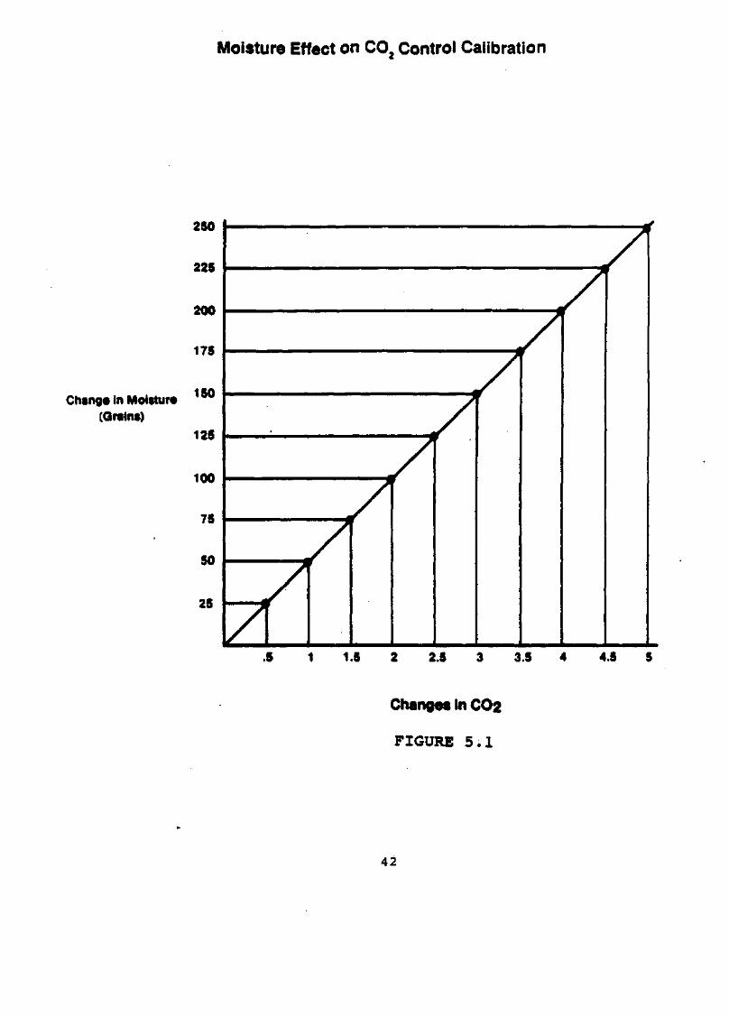
Thermal conductivity of the incubator atmosphere isaffected not only by the quantity of CO, present, but bythe quantity of water vapor present in the incubatoratmosphere as well. This effect is linearly related to theabsolute humidity of the atmosphere (See graph on page42).
In monitoring the effects of CO^, absolute humidity mustbe held constant so any change in thermal conductivity iscaused only by a change in the C02 concentration. Underthe worst circumstances, a change in absolute humiditycould cause such a significant change in thermalconductivity that the controller could shift the C02content by as much as 4%.
37

Maintaining the water level inside the incubator is arelatively simple procedure. We cannot emphasize stronglyenough the importance of keeping the humidity in theincubator constant. Any water pan, used in lieu offlooding the incubator floor, must be stainless steel andat least 187 square inches of surface area. Our testsindicate that smaller pans, bowls or non-metallic pans donot provide adequate humidification, which can lead toincubator humidity variations with ambient humidityshifts, resulting in C02 changes in the incubator.
When operating a dry incubator, as opposed to a humidifiedone, ambient humidity fluctuations will affect C02calibrations. Since the fluctuations possible in extremeambient changes have less effect on the total absolutehumidity, the C02 calibration can be affected by as muchas 1.5%.
When a change in humidity or temperature is needed, theC02 control can be easily zeroed for the new condition.
One additional note: Temperature changes have littleaffect on CO, calibration, but do cause large changes inthe absolute numidity which is reflected in changes in C02calibration.
5.3 CONTROL PANEL
1) FILL/DRAIN FITTING AND VENT HOLE
The fill/drain fitting is located on the center frontof the unit, directly above the door. This fitting isto facilitate filling and draining of the water jacketwithout having to move the unit. The vent hole,located directly below the fill/drain fitting, behindthe front door, allows the air displaced by waterentering the jacket to escape. It also preventsdistortion of the chamber by allowing air to escape asthe unit expands and contracts during heating andcooling. Under no circumstances should the vent beplugged.
2) POWER SWITCH AND PILOT LIGHT
The main power switch controls the ON/OFF power to theunit. The power pilot light is activated when thepower switch is on, and the unit is receivinc power.
38

3) CIRCUIT BREAKER (RESET)
The 5 amp circuit breaker for the incubator (labeled"Reset") can be pushed to reset the incubator powersupply within a few seconds after the breaker hastripped. If it trips a second time, the unit should bechecked by a qualified electrician.
4) VARIABLE/37C SWITCH, TEMP CONTROL, AND HEATER PILOTLIGHT
When the Variable/37C switch is set to the 37C (up)position, chamber temperature will automatically bemaintained at +37 degrees C. If necessary, the 37Ccontrol can be calibrated via the calibration screwlocated at the lower left side of the temperaturecontrol dial. See Section 7.3 for recalibrationinstructions for the 37 degrees C setting.
When the switch is set to the Variable (down)position, control is assumed by the temperaturecontrol potentiometer. The numbers (0 to 60) aroundthe control knob indicate approximate setpoint valuesin degrees Centigrade. Any value between +5 degrees Cabove ambient temperature and 50 degrees C may beselected. The heater pilot light will be activatedwhenever the heater is energized.
5) GAS SAMPLE PORT
A sample port for checking CO2 percentage byindependent means (e.g. FYRITE or similar C02measuring device). See Section 6.9 for details on theproper use of the FYRITE.
IMPORTANT:
THE SAMPLE PORT SHOULD NEVER BE CAPPED, AS IT SERVESAS A VENT FOR THE INCUBATOR CHAMBER.
6) SETPOINT ADJUSTMENT TOOL
A small screwdriver, located adjacent to the sampleport, has been provided for setting the CO2 andovertemp setpoints. Pull out on the knob to releasethe screwdriver.
39

5.4 C0 2 MODULE
1) CO2 POWER SWITCH
The CO, power switch controls the electrical power tothe CO2 system, and it must be ON when the incubatoris to be operated with C0 2. The switch should beturned on as soon as power is applied to the unit toallow the CO2 system to warm up.
2) CO2 CONTROLLER AND DIGITAL DISPLAY
The LCD digital readout on the C0 2 module continuallydisplays the percent of C0 2 in the chamber. Thesetpoint is displayed when the C0 2 set/silence buttonis pushed.
C0 2 setpoint is changed by pushing the CO2 set/silencebutton and rotating the C0 2 setscrew to the desiredpercentage.
3) AUDIBLE C0 2 ALARM AND PILOT LIGHT
The audible C0 2 alarm and pilot light are activatedwhen the percent C0 2 deviates from setpoint by plus orminus 1% (nominal) for longer than approximately fourminutes.
4) SET/SILENCE PUSH BUTTON
When pushed, the set/silence button will silence theCO, alarm and de-energize the alarm light. The alarmwill remain deactivated until another alarm conditionoccurs. This button must be pushed to set or displaythe C0 2 setpoint.
5) ALARM DISABLE SWITCH
NOTE: It is necessary to pull the C0 2 module out slightlyto gain access to the alarm disable switch.
When the switch is in the DISABLE position, the C0 2alarm is completely disabled. When the switch is setto the NORMAL position, the alarm system is operativeand can be silenced via the set/silence button.
40
6) C0 2 INJECT LIGHT
The C0 2 inject light is activated whenever there is ademand for C0 2 to meet setpoint requirements, sincethe CO, inject light is independent of the C0 2 alarm,it will continue to signal a need for C0 2 when the C0 2alarm is set to either the defeat or silence position.
7) C0 2 ZERO ADJUSTMENT
The CO, zero adjustment is used for zeroing the C0 2controller to specific control conditions. It is theONLY user calibration adjustment on the CO, module.All internal adjustments are for qualified servicepersonnel ONLY.
5.5 ALARM/MONITOR MODULE
1) OVERTEMPERATURE CONTROLLER AND PUSH TO SET BUTTON
The overtemperature setpoint is displayed when the"PUSH TO SET" button on the module is pushed. Overtempcontrol point is adjusted by pushing the set buttonand rotating the setscrew on the module to the desiredsetpoint.
2) OVERTEMP ALARM AND PILOT LIGHT
The overtemperature audible alarm and pilot light areactivated in the event of an overtemp condition. Oncethe alarm has been activated, it can only be silencedby the temperature in the chamber returning to normalor by readjusting the overterop setpoint to a valueabove the chamber temperature.
3) ADD WATER PILOT LIGHT AND AUDIBLE ALARM
The add water pilot light and audible alarm areactivated whenever the water level in the water jacketis low. The alarm will be deactivated only whenapproximately 1 liter of water has been added throughthe fill/drain fitting. (See Sections 4.10).
41
Moisture Effect on CO2 Control Calibration
Chang* in Moisture(Grains)
1 1.5 2 2.5 3 3.5 4 4.5 5
Changes in CO2
FIGURE 5 . 1
42

SECTION 6 - ROUTINE MAINTENANCE
TABLE OF CONTENTS
6.1 Installing the Decontamination Kit
6.2 Disinfecting the Incubator Interior
6.3 Cleaning the Cabinet Exterior
6.4 Draining the Water Jacket
6.5 Changing the CO2 Filter
6.6 A Word About C02 Test Instruments
6.7 Overview of the Fyrite CO2 Analyzer
6.8 Fyrite Operating Precautions
6.9 Operating the Fyrite
6.10 Checking the Fyrite Fluid Strength
6.11 Raising or Lowering the Fyrite Fluid Level
43

INSTRUCTION SHEET #7190028REVISED 8/
INSTRUCTIONS FOR INSTALLINGDECONTAMINATION KIT# 190028
1) DISCONNECT INCUBATOR FROM POWERSUPPLY.
2) Remove shelves, duct sheets and blower channelfrom incubator interior.
3) Remove blower wheel. To remove the blowerwheel, grasp it as shown in Figure #1 andpull down firmly.
4) Match blower wheel from kit with blowerwheel that was removed in Step #3.IMPORTANT! THE BLOWER WHEELREPLACEMENT MUST BE ANIDENTICAL MATCH. Place new blowerwheel over motor shaft and push blowerwheel up against snap ring (if present).Confirm that blower wheel rotates freely.
5) Next locate and remove the four wing nuts thatsecure the motor mounting plate to the incubatorceiling, shown in Figure #2.
6) Carefully pull blower motor assembly down intochamber area. NOTE: ON SOME MODELS, THEBLOWER MOTOR ASSEMBLY MAY DROPDOWN ONLY 1-1/2 TO 2 INCHES.
7) Slide the motor mounting gasket over the motormounting plate, as shown in Figure #3. Discardgasket.
8) Install the new motor mounting gasket over thefour studs, located on the incubator ceiling, asshown in Figure #4.
NOTE: THE MOTOR MOUNTING GASKET MUSTLIE FLAT BETWEEN THE MOTOR MOUNTINGPLATE AND THE INCUBATOR CEILING. TIGHTENALL FOUR WING NUTS FIRMLY TO ENSURE AGOOD SEAL.
Figure #1
Figure #2
Figure #3
Figure #4

THE FOLLOWING STEPS APPLY TO AUTOMATICCO2 AND AUTOMATIC O2/CO2 INCUBATORS.FOR CONSTANT FLOW INCUBATORS, SKIP TOSTEP #12.
9) Remove the two wing nuts and large flat washerthat secures the CO2 sensor, shown in Figures #5 . Allow sensor to drop down into chamber area.Disconnect sensor at electrical connector.
10) Peel o-ring off sensor and replace it withthe new o-ring provided in kit, shown inFigure #7.
Figure #5
11) Electrically reconnect CO2 sensor.Reinstall CO2 sensor to originalposition. Tighten wing nuts firmlyto ensure proper sealing.
12) Reinstall blower channel, duct sheets andshelves. Reconnect incubator to power supply.
lit
Figure #6
Figure #7

6.2 DISINFECTING THE INCUBATOR INTERIOR
The incubator can be easily disinfected in about 30minutes. Forma recommends the use of ColdSpore™ . Dilutewith sterile distilled water (50K Ohm to 1 Meg Ohm).
1) Remove shelves and duct sheets, and clean all interiorsurfaces, taking care not to saturate the CO 2 sensor.
2) Rinse the surfaces at least twice with steriledistilled water (50K Ohm to 1 Meg Ohm), or until youare satisfied that all of the disinfectant-detergenthas been removed.
3) Thoroughly clean the door gasket.
4) Clean inside of glass door with solution, and rinsewith sterile distilled water (50K Ohm to 1 Meg Ohm).
5) Wash or autoclave the shelves and duct sheets withsolution.
6) Rinse with sterile distilled water.
REPEAT RINSING UNTIL YOU ARE SATISFIED THAT ALL OF THEDISINFECTANT-DETERGENT HAS BEEN REMOVED.•
7) If desired, all surfaces can then be rubbed or sprayedwith 70% alcohol.
8) Reinstall the duct sheets and shelves.
NOTE: AFTER COMPLETING THE DECONTAMINATION PROCEDURE, ITIS RECOMMENDED THAT THE INCUBATOR BE RUN FOR 24HOURS TO ASSURE REMOVAL OF TRACE VAPORS, BEFOREPLACING ANY VALUABLE CONTENTS INSIDE THE INCUBATORCHAMBER.
WARNING: ALCOHOL, EVEN A 70% SOLUTION, IS VOLATILE ANDFLAMMABLE. USE IT ONLY IN A WELL VENTILATED AREATHAT IS FREE FROM OPEN FLAME. IF ANY COMPONENT ISCLEANED WITH ALCOHOL, DO NOT EXPOSE THE COMPONENTTO OPEN FLAME OR OTHER POSSIBLE HAZARD.
CAUTION: DO NOT USE STRONG ALKALINE OR CAUSTIC AGENTS.STAINLESS STEEL IS CORROSION RESISTANT, NOTCORROSION PROOF.
46

CAUTION: DO NOT USE SOLUTIONS OF SODIUM HYPOCHLORITE(PUREX, CLOROX, ETC.)/ AS THEY MAY CAUSE PITTINGAND RUST.
6.3 CLEANING THE CABINET EXTERIOR
The incubator exterior may be cleaned with soap and waterand a general use laboratory disinfectant. A cleaningchart has been provided at the rear of the manual.Information about disinfectants, recommended by FormaScientific, Inc. is included as a supplement to thismanual.
6.4 DRAINING THE WATER JACKET
For best results, the water in the water jacket should bechanged yearly.
1) Disconnect the unit from the power supply.
2) Remove the plastic "protective" cap from thefill/drain fitting and attach the 3/8" I.D. vinyltubing. Attach funnel to open end of tubing.
3) Prime the water line by holding the tubing straight upand pouring water slowly into the funnel until the,tubing is completely filled.
4) Quickly drop the water line to a drain or largebucket. If the tube has been filled correctly, thewater should siphon out of the jacket.
5) See Section 4.10 to fill the water jacket.
6.5 CHANGING THE CO, FILTER(FOR QUALIFIED SERVICE PERSONNEL ONLY!)
NOTE: Under conditions of normal usage, and dependent uponthe purity of gas being used, the CO2 filter shouldbe good for approximately five years.
If the CO, filter becomes clogged, replace with Formastock #770001.
1) Disconnect the unit from the power supply.
2) Remove screws securing side service panel.
3) Remove and replace the filter.
47
6.6 A WORD ABOUT CO2 TEST INSTRUMENTS
During the course of our research into the use of FormaAutomatic CO2 incubators, we discovered that the beststandard available for zeroing or calibrating our CO2controller is air, which typically contains 0.033% co2 byvolume. Variations from this figure are insignificant.
As previously noted, it is extremely important that anyForma automatic CO2 incubator be zeroed to air (SeeSection 4.15). C02 TEST INSTRUMENTS SHOULD BE USED AS ASECONDARY CHECK OR TO CHECK CO2 AT OPERATING LEVELS ONLY!
Because sampling technique is so important to theeffective use of CO2 test instruments, we have includedinformation in this manual on the use of the most commonlyused test instrument, the FYRITE. REMEMBER THAT THE FYRITESHOULD BE USED FOR CHECKING PURPOSES ONLY; NOT FOR THEACTUAL ZEROING OF FORMA EQUIPMENT!
6.7 OVERVIEW OF THE FYRITE CO2 ANALYZER
Many of our customers use FYRITE CO, Analyzers as anindependent means of checking the CO2 level in theirincubators. We do not want to discourage this practice,but we feel that the safe and correct use of this testinstrument is of vital importance to us. In an effort toinform our customers about the use of the FYRITE, we havecompiled the following hints and instructions from theFYRITE instruction manual 11-9026, dated January, 1980.
WARNING: THE FLUID USED IN THE FYRITE CO, ANALYZERCONTAINS POTASSIUM HYDROXIDE AND IS CORROSIVE. ITCONTAINS POISONOUS CHEMICALS AND SHOULD NOT BETAKEN INTERNALLY. IN THE EVENT OF BODY CONTACT:
ANTIDOTES
EXTERNAL: FLOOD WITH WATER, THEN WASH WITH VINEGAR.
INTERNAL: GIVE VINEGAR, OR JUICE OF LEMON, GRAPEFRUIT, ORORANGE COPIOUSLY. FOLLOW WITH OLIVE OIL.
EYES: FLOOD WITH WATER, THEN WASH WITH A 5% BORIC ACIDSOLUTION.
CALL PHYSICIAN
48

6.8 FYRITE OPERATING PRECAUTIONS
1) DO NOT invert the FYRITE when the plunger isdepressed.
2) DO NOT hold the FYRITE near your face when the topplunger is depressed.
3) ALWAYS hold the FYRITE by the fins to prevent heattransfer from your hands.
4) ALWAYS moisten the filter in the sampling tube beforetaking a sample. Failure to do so will result ininaccurate readings.
5) For maximum accuracy, the FYRITE MUST be at ambienttemperature. DO NOT store the FYRITE in a locationsubject to extreme temperatures (such as the trunk ofa car or a windowsill).
6) Check the strength of the FYRITE fluid whenever theinstrument is used. See Section 6.10 for instructionson checking the fluid strength.
6.9 OPERATING THE FYRITE
1) ,Hold the FYRITE upright and away from your face. Pressthe plunger momentarily to vent the tester.
2) Invert the FYRITE to drain the fluid into the top.
3) Turn the FYRITE upright, and allow the fluid to drainto the bottom.
4) Hold the FYRITE at eye level. Loosen the locknut atthe rear of the scale. Slide the scale until the to ofthe fluid column lines up with the zero on the scale.Tighten the locknut.
NOTE: Either the top or the bottom of the meniscus can beused for setting the zero as long as the same pointis used when making measurements.
5) Attach the open end of the rubber gas sampler hose tothe sample port on the incubator. DO NOT attach thetube to the FYRITE tester at this time. Pump theaspirator bulb a few times to clear the air from thesampler line.
49

6) Hold the FYRITE upright, and place the rubberconnector tip from the sampler tube over the plungervalve, and pump the aspirator bulb at plunger valveduring the final squeeze.
7) Invert the FYRITE, and allow all the liquid to drainto the top. Turn upright, and allow all the liquid todrain to the bottom. Repeat once.
8) Momentarily hold the FYRITE at a 45 degree angle toallow the fluid droplets to drain to bottom.
9) Hold the FYRITE upright. Allow the fluid a few secondsto stabilize. Determine the percent CO, from the levelof the fluid column. A delay of 5 to 10 seconds intaking the reading may result in a slight error; alonger delay may result in a substantial error.
10) Repeat steps 6 through 10 until two consecutivereadings agree.
11) Remove the FYRITE hose from the sample port to allowthe chamber to breathe.
NOTE: When used correctly, the FYRITE is accurate towithin +1/2% of actual CO2 value. Incorrect samplingtechnique can cause an error of as much as 4%.
6.10 CHECKING THE FYRITE FLUID STRENGTH
After taking a reading with the FYRITE, do not vent thesample. Invert the FYRITE again, and take another reading.If there is an increase of 1/2% or more on the secondreading, fluid replacement is necessary.
Fluid strength can also be checked by testing a certifiedgas sample containing a known C0 2 concentration. FreshFYRITE fluid should be good for approximately 350 samples.
NOTE: The dark red fluid floating on the top of the FYRITEsolution is normal. It has been added to thesolution to prevent excessive foaming at themeniscus and does not indicate defective fluid.
CAUTION: IF REPLACEMENT OF THE FLUID IS NECESSARY,CAREFULLY FOLLOW THE DIRECTIONS ON THE PACKAGE.REMEMBER THAT THE FLUID IS POISONOUS AND CAUSTIC.
50

6.11 RAISING OR LOWERING THE FYRITE FLUID LEVEL
With the FYRITE vented and in the vertical position, itshould be possible to adjust the zero scale to the top ofthe fluid column. If this is not possible, fluid should beadded or removed.
TO ADD FLUID: Hold the FYRITE upright, and press theplunger. Add clean tap water a few drops at a time.
TO REMOVE FLUID: See your FYRITE manual.
51

SECTION 7 - SERVICE
TABLE OF CONTENTS
7.1 CO2 Control Calibration
7.2 37C Control Calibration
7.3 Replacing the C02 Sensor
7.4 Replacing the Triac
7.5 Replacing the CO2 Solenoid
7.6 Replacing the Temperature Control
7.7 Replacing Pilot Lights
7.8 Replacing the Circuit Breaker
7.9 Replacing the Power Switch
7.10 Replacing the Thermistors
7.11 Replacing the 0.3 Amp Fuse
CAUTION: SERVICING OF THE UNIT SHOULD BE PERFORMED BYQUALIFIED SERVICE PERSONNEL ONLY.
52

7.1 C0 2 CONTROL CALIBRATION
The adjustment will be necessary only under the followingconditions. DO NOT recalibrate the incubator for any otherreasons!
1) After the CO 2 controller is replaced.
2) After the C0 2 sensor is replaced.
3) If there is reason to believe that the controller haspreviously been calibrated incorrectly.
TOOLS NEEDED:
1) Calibration screwdriver (provided).
2) Circuit Board Extender Card.
3) FYRITE CO 2 Analyzer(See Section 6.9 for proper usage).
CALIBRATION PROCEDURE
STEP l: STABILIZE THE INCUBATOR AT OPERATING TEMPERATURE ANDHUMIDITY WITH NO CO2 IN THE CHAMBER.
1.1,TURN POWER OFF TO C0 2 MODULE!
1.2 Remove the CO, Module, and insert the extender cardinto card guides. Push extender card in firmly. PlugCO 2 Module into the connector on the front of theextender card.
CAUTION: TAKE CARE TO PLUG-IN THE MODULE RIGHT SIDE UP,OTHERWISE DAMAGE WILL OCCUR TO THE CO2 MODULE.
1.3 Turn OFF the CO 2 supply at the source.
1.4 Fill the humidity pan with sterile distilled water.
1.5 Turn unit on and allow the chamber temperature andhumidity to stabilize. This will take a minimum of 8hours if the temperature setpoint has been recentlychanged. Allow 3 days on initial start-up.
1.6 Turn the span pot counterclockwise 10 turns.
53

STEP 2: ADJUST THE ZERO POT
2.1 Using the small screwdriver mounted on the controlpanel, adjust the CO2 control zero pot to read 00.0 onthe digital display.
2.2 Wait 5 minutes, and repeat as necessary until thedisplay is stable.
STEP 3: ADJUST THE SPAN POT
3.1 Turn ON the CO2 at the supply.
3.2 Turn the CO, setpoint to the desired operating level.Allow the C02 to stabilize at the desired level on thereadout and control (inject light will cycle) for aminimum of 15 minutes.
3.3 Using a FYRITE or other measuring device, check theCO2 level in th<readings agree.CO2 level in the chamber until two consecutive
3.4 Turn the C02 setpoint to 0.0% to prevent CO2 from,being injected into the chamber during the adjustment.
3.5 Adjust the span pot so the digital display agrees withthe FYRITE reading.
3.6 Turn the setpoint back to the desired operating leveland allow the C02 to control and stabilize for aminimum of 15 minutes.
3.7 Check the CO2 in the chamber with a FYRITE or similardevice until two consecutive readings agree. If thedigital display is within plus or minus 1.0% of theFYRITE reading, proceed to Step 4. If the reading isnot within plus or minus 1.0%, repeat steps 3.4through 3.7.
STEP 4: RE-CHECK THE ZERO ADJUSTMENT
4.1 Turn OFF the CO2 at the supply.
4.2 Open both doors wide for 45 seconds. Close the doors,and allow a minimum of 30 minutes for the incubator tostabilize and assure a zero C02 condition in thechamber.
54

4.3 If the readout is greater than 00.4, repeat the dooropening for 15 seconds, and again allow the incubatorto stabilize for a minimum of 15 minutes. If thedisplay is not less than the previous reading, consultthe factory. If the display now reads 00.4 or less,re-adjust the zero pot so the display reads 00.0.
STEP 5: CHECK THE C0 2 AT THE DESIRED SETPOINT
5.1 Turn ON the C0 2 at the supply.
5.2 Turn the CO 2 setpoint to the desired level.
5.3 Allow the incubator to reach setpoint and control fora minimum of 30 minutes.
5.4 Check the CO2 with a FYRITE or similar device untiltwo consecutive readings agree. If the FYRITE anddisplay are not within 1.0%, consult the factory.
NOTE: After proper calibration the CO, display will bemore accurate than the FYRITE, Because the zeroadjustment was made using atmospheric conditions.
7.2 37C CONTROL RECALIBRATION
If the digital display indicates a temperature other than37C when the chamber temperature has stabilized (tempselect switch set to 37C), it may be necessary torecalibrate the adjustment.
TO RECALIBRATE:
1) Make a note of how much the display varies from 37C.
2) Locate the 37°C recalibration adjustment set screwbetween the 37°C slide switch and the temperatureadjustment knob.
3) Using calibration screwdriver mounted on controlpanel, adjacent to the sample port, turn thecalibration screw one turn clockwise for every halfdegree that the display is below 37C. Turning thescrew counterclockwise will lower the temperature.
55

4) Allow the temperature to stabilize, and check thedisplay again. If it still varies significantly,repeat steps 1 through 3.
CAUTION: SERVICING SHOULD BE PERFORMED BY QUALIFIEDSERVICE PERSONNEL ONLY. DISCONNECT THE INCUBATORFROM THE POWER SOURCE BEFORE STARTING SERVICEPROCEDURES.
7.3 REPLACING THE CO2 SENSOR
1) Turn the power switch "OFF" and disconnect the unitfrom the power supply.
2) Remove shelves, duct sheets, and blower channel fromthe chamber.
3) Locate CC>2 sensor in the center of the incubatorceiling, and remove wing nuts. The sensor will dropdown.
4) There is a clip that connects sensor wiring toincubator wiring. To open the clip, pull out slightlyon the clip tab to release sensor.
5) Remove the O-ring, and place it on the new sensor.
6) Clip the new C0 2 sensor onto the incubator wiring, andreturn sensor to original opening. Be sure to tightenwing nuts securely so the 0 ring seals properly.
7) After the sensor has been replaced, recalibrate theCO2 controller according to instructions in Section7.1.
7.4 REPLACING THE TRIAC
1) Turn the power switch "OFF" and disconnect the unitfrom the power supply.
2) Remove the screws securing the right side accesspanel. Remove panel and set aside.
3) Remove two mounting screws that secure triac.
4) Carefully disconnect wires to triac, and make note oftheir configuration to insure proper connection to newtriac.
56
5) Remove triac from unit. Note thermal compound betweenbase of triac and back of control panel housing. Ifnecessary, reapply more thermal compound beforeinstalling new triac.
6) Install the new triac by reversing the aboveprocedure. Be sure to install wiring in sameconfiguration as old triac.
7.5 REPLACING THE C0 2 SOLENOID
1) Turn the power switch "OFF" and disconnect the unitfrom the power supply.
2) Remove the screws securing the right side accesspanel. Remove panel and set aside.
3) Locate CO, solenoid in the upper rear of the controlpanel, and disconnect tygon tubing attached to it.Note how tubing is installed so that it can beattached to new solenoid in same way.
4) Remove the screws that hold the solenoid in place.
5) Disconnect wiring to solenoid, making note of itsconfiguration.
6) Remove solenoid, and replace with new solenoid, byreversing above procedure. Be sure to connect wiringand tubing as noted during removal of old solenoid.Note the flow direction marked on solenoid.
7.6 REPLACING THE TEMPERATURE CONTROL
1) Turn the power switch "OFF" and disconnect the unitfrom the power supply.
2) Remove the screws securing the right side accesspanel. Remove panel and set aside.
3) Remove temp control knob by loosening two Allen headscrews recessed in knob.
4) Remove nut on shaft, then remove nut on back of panelbehind control knob.
5) Remove wiring to temp control, and make note of itsconfiguration.
6) Remove control, and replace it with new control byreversing above procedure.
57

NOTE: It may be necessary to "pry-loose" the defectivecontrol since it is secured with sticky tape. Wheninstalling the new control remove cover from thetape and align carefully into place.
7.7 REPLACING PILOT LIGHTS
1) Turn the power switch "OFF" and disconnect the unitfrom the power supply.
2) Remove the screws securing the right side accesspanel. Remove panel and set aside.
3) Disconnect wiring behind defective light, and breakretaining clip loose. Remove pilot light.
4) Insert the new pilot light from front, and install newretaining clip.
5) Rewire pilot light in same configuration as old light.
7.8 REPLACING THE CIRCUIT BREAKER
1) _Turn the power switch "OFF" and disconnect the unitfrom the power supply.
2) Remove the screws securing the right side accesspanel. Remove panel and set aside.
3) Remove nut securing circuit breaker to control panel.
4) Remove the wiring, and note its configuration.
5) Install new circuit breaker by reversing aboveprocedure.
58

7.9 REPLACING THE THERMISTOR
1) Turn the power switch "OFF" and disconnect the unitfrom the power supply.
2) Remove the screws securing the top access panel.Remove panel and set aside.
3) Locate thermistors by lifting insulation in the frontleft-hand corner top of the incubator. Remove silasticaround defective thermistor cable.
4) Pull the defective thermistor out of the probe sheath.
5) Cut wires to defective thermistor, making note oftheir configuration.
6) Attach new thermistor by use of electrical in-lineconnectors.
7) Install new thermistor by reversing above procedure.Take care not to damage the probe tip, make sure thatthe probe is fully inserted into the sheath. AlsoRESEAL around cable with silastic or similar material.
7.10 REPLACING THE 0.3 AMP FUSE
The 3/10 amp fuse is located directly above the line cord,and is labeled.
1) Disconnect all power to the incubator.
2) Remove the screws securing the side access panel.Remove panel and set aside.
3) Use a fuse puller, a small screwdriver, pry to liftone end of fuse from clip. Grasp fuse and remove fromholder. Discard fuse.
NOTE: Use fuse puller carefully. Use of a puller on smallfuses can result in breakage of the glass fusebarrel.
4) Insert a new 0.3 Amp fuse into holder and press endsinto clips.
NOTE: 3/10 Amp fuses have very fine elements. Continuitytest fuse before installation to be sure element isintact.
59

5) Reinstall the right side access panel.
6) Connect power to incubator. Turn "POWER" switch to"ON" and check operation of controls.
60

SECTION 8 - SPECIFICATIONS
Table of Contents
8.1 Capacity
8.2 Weight
8.3 Dimensions
8.4 Construction
8.5 Shelves
8.6 Alarm/Monitor Module
8.7 C02 Module
8.8 Temperature Control
8.9 Heaters
8.10 Blower
8.11 Fittings
8.12 Electrical Characteristics
8.13 Performance Data
61

SECTION 8 - SPECIFICATIONS
Models 3546/3548
8.1 CAPACITY
Chamber Capacity: 5.7 Cubic Feet 0.16 Cubic MetersWater Jacket Volume: 12.9 Gallons 49 LitersHumidity Reservoir Capacity: 1.46 Gallons 5.5 LitersHumidity Pan Capacity: 6.375 Liters
8.2 WEIGHT
Net Weight Without Water: Approx. 180 lbs.Approx. 81.6 kgs.
Net Weight With Water: Approx. 267.5 lbs.Approx. 121.3 kgs.
Shipping Weight (Motor): 270 lbs. Nominal122 kg Nominal
8.3 DIMENSIONS
Exterior: 31.2" W x 36.1" H x 23.8" F-B79.2 cm W x 91.7 cm H x 60.4 cm F-B
Interior: 26.8" H x 18.6" W x 18.8" D68.0 cm H x 47.2 cm W x 47.7 cm D
8.4 CONSTRUCTION
Exterior: 18 Ga. Cold Rolled SteelInterior: 20 Ga. Stainless Steel Type 304 2-B FinishInsulation: 1-1/2" FiberglassInner Door Gasket: SiliconeOuter Door Gasket: 4 Sided Molded Magnetic VinylFinish: Powder CoatedBristol Gray & Windsor Blue Trim
63

8.5 SHELVES
Capacity: 22 (5 Provided)Dimensions: 17.75" W x 17.75" D
45.2 cm W x 45.2 cm DConstruction: 18 Ga. Electropolished Stainless Steel
Type 304Usable Shelf Area (per shelf): 2.2 Square FeetUsable Shelf Area (maximum): 48.4 Square FeetFlatness: +/- 0.032" Off Horizontal PlaneClearance: Adjustable on 1" Centers
8.6 ALARM/MONITOR MODULE
Sensor: ThermistorControl Sensitivity: +/- 0.1 Degree CReadout: LCDSetpoint: Digital W/Screwdriver AdjustReadability: 0.1 Degree CAccuracy: +/- 0.2 Degrees CAlarm Setability: 0.1 Degree C
8.7 CO2 MODULE
Sensor: Matched ThermistorsController: Thermal ConductivitySensitivity: +/- 0.1% C02Readout: LCDSetpoint: Digital with Screwdriver AdjustReadability: 0.1% CO2Accuracy: 0.1% CO,Alarm Differential & Delay: +/- 1% (nominal) for longerthan approx. 4 minutesSupply Voltage: +/- 15V
8.8 TEMPERATURE CONTROL
Sensor: ThermistorController Type: Proportional, Zero-SwitchingRange: 0 to 60 Degrees CSensitivity: +/- 0.05 Degrees C
8.9 HEATERS
Chamber: 260 WattsDoor: 5 Watt Continuous, 120 Watt CycledTop: 6 Watts
64

8.10 BLOWER
CFM: 7.5Wheel Material: PolypropyleneMotor: 1/200 HP, 3000 RPM, 2 PoleExternally Mounted, Internally Removable
8.11 FITTINGS
Fill & Drain Fitting: 1/4" FPTAccess Port: 1.250" PluggedCO, Connection: 1/4" Serrated Fitting
1/4" I.D. TubingSample Port: 1/4" O.D.
1/4" I.D. Tubing
8.12 ELECTRICAL CHARACTERISTICS
Main: 90-130 VAC, 50/60 Hz, 4 FLACircuit Breaker: 5 AmpsPower Switch: 2 Pole
MODEL 3548:Main: 180-260 VAC, 50/60 HZ, 1.9 FLACircuit Breaker: 5 AmpsPower Switch: 2 Pole
8.13 PERFORMANCE DATA
TemperatureRange: 5 Degrees C above ambient to 60 Degrees CControl Tolerance: +/-0.02 Degrees C at 37 Degrees C
in 72 Degrees F ambient
co2Range: 0 to 20%Control Tolerance: Better than +/- 0.1%Consumption § 5% CO2: 1.7 Liters/Hr. +7.2 Liters/15 Sec.
Door Opening
* - to within 1/2 degree C** - to 4.5% CO2 (setpoint 5% C02)*** - to 97% RH
65
9.1 AUXILIARY EQUIPMENT
1) ELECTROPOLISHED STAINLESS STEEL SHELF
The perforated shelf is square for easy installation.22 shelf capacity. Catalog # 224140
2) TISSUE CULTURE SHELVES
These 11" x 16" stainless steel shelves for culturedishes are designed for stacking to increase incubatorstorage space. Minimum order of 6 shelves. Catalog #500171
3) FYRITE CO 2 ANALYZER KIT
For checking chamber C0 2 (0-20%) level in the chamber.Connects to the gas sample port on the control panel.Kit comes complete with aspirator, sampling tube, andcarrying case. Catalog # 220012
4) EXTRA FYRITE FLUID
For replacing Fyrite tester fluid. Three bottles percarton. Catalog # 220051
5) . DIGITAL THERMOMETER
Hand-held, the size of a pocket calculator, it featuresclear liquid crystal readout of temperature from -99.9to +99.9 degrees C. Ideal for general laboratory use.Catalog # 853227
6) TWO STAGE PRESSURE REGULATOR
Controls C0 2 cylinder gas pressure. First stage reducestank pressure to pre-set intermediate level. Secondstage reduces pressure to recommended incubator inletpressure. Permits stable C0 2 flow on high or low demandthrough the entire cylinder supply. Catalog # 965010
7) C0 2 GAS GUARD
For use with automatic C0 2 incubators only. Protectsdual tank C0 2 supply by automatically switching toanother tank when one supply is exhausted. Audiblealarm warns of tank depletion; reset button silencesthe alarm. Manual tank switch-over included.Model # 3030.
66

8) REPLACEMENT C0 2 FILTER
Disposable 99.97% Microbiological filter to replace theinline CO, filter when it becomes clogged.Catalog # 770001
9) DISINFECTION KIT
Includes parts needed for improved disinfection of theincubator. Includes disposable blower wheel, 0 ring forthe CO, sensor, and motor mounting gasket.Catalog # 190247
10) LABORATORY DISINFECTANT
ColdSpore™ Concentrate (4 bottles) Catalog/ 130043ColdSpore™ (spray bottles) Catalog/ 130045
11) HUMIDITY PAN
This humidity pan is made of stamped (seam-free) 304stainless steel and will hold 6.375 quarts (6 liters)of water. Cleaning and decontamination is very easy dueto the coved corners and seamless construction. Catalog# 237001
12)' HYGROMETER
For measuring chamber humidity. This instrument has a4" dial and a range of 0 to 100% rh. Catalog # 155010
13) GLASS THERMOMETER
For independently measuring chamber temperature. Rangefrom 0 to 100 degrees C. Catalog # 285722
67

8ECTI0N 10 - PARTS LIST
PARTS LIST
STOCK # DESCRIPTION
770001 CO, Disposable Filter250085 C02 Solenoid 12VDC, 3W300164 Overtemp Relay431142 Gasket, Magnetic400296 Silicon Feather Gasket230094 Fuse .3A (Slow-Blow Type)280004 #312 Green Pilot Light280006 #312 Amber Pilot Light111008 Clip, Mounting, Pilot Light285379 25A Triac100071 Blower Wheel227175 Blower Motor231011 Alarm/Monitor Module231142 CO2 Control Module231047 Temperature Control290027 IK, Thermistor Cable
68