scientific data systems · (24-bit fraction, 9-blt exponent) (39-bit fraction. 9-bit exponent)...
TRANSCRIPT

SCIENTIFIC DATA SYSTEMS
SDS 900 SERIES COMPUTERS
(
(
Individual characteristics
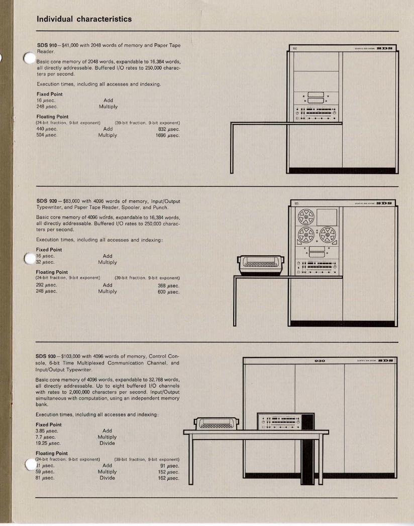
SOS 910-$41,000 with 2048 words of memory and Paper Tape Reader.
Basic core memory of 2048 words , expandable to 16,384 words, all directly addressable . Buffered I/O rates to 250,000 characters per second.
Execution times , including all accesses and indexing.
Fixed Point 16/Lsec. 248/Lsec .
Floating Point
Add Multiply
(24-bit frac ti on. 9-bit exponent) (39-b it frac t ion, 9-b it exponent)
440/Lsec. 504/Lsec .
Add Multiply
832/Lsec. 1696/Lsec.
SOS 920 - $83,000 with 4096 words of memory, Input/Output Typewriter, and Paper Tape Reader, Spooler, and Punch .
Basic core memory of 4096 wci'rds, expandable to 16,384 words, all directly addressable. Buffered I/O rates to 250,000 characters per second.
Execution times, including all accesses and indexing :
Fixed Point 16/Lsec. 32/Lsec.
Floating Point
Add Multiply
(24-b it fra ct ion , 9-blt exponent) (39-bit fracti on. 9-b it exponent)
292/Lsec. 248/Lsec.
Add Multiply
368/Lsec. 600/Lsec.
SOS 930-$103,000 with 4096 words of memory, Control Conso le, 6-bit Time Multiplexed Communication Channel, and Input/Output Typewriter.
Basic core memory of 4096 words, expandab le to 32,768 words, all directly addressab le. Up to eight buffered I/O channels with rates to 2,000,000 characters per second. Input/Output simultaneous with computation, using an independent memory bank.
Execution times , including all accesses and indexing:
Fixed Point 3.85/Lsec. 7.7/Lsec. 19.25 iJ.sec.
Floating Point
Add Multiply Divide
(24-bit fraction , 9-bit exponent) (39-bit fraction, 9-bit exponent)
31 iJ.sec. 59 iJ.sec. 81 iJ.sec.
Add Multiply Divide
91 iJ.sec. 152 iJ.sec. 162 iJ.sec.
910
o~o oc=Jo
910 sc"."',eo''' '''''YI H:K:»S
*' ,
@ @ ~g~ r:r.C~S\ ° ~6~ o.~o 0c==J0
q(~) ? {) • i ...; •• ___ ......
~ -ll~;~:~,;~:~:-;~·~;~?

SOS 900 Series input! output
SDS 900 Series computers have unusually fast and flexible input/output capabilities that permit the user to take full advantage of high internal computing speeds. The various input/output systems are designed so that 900 Series computers can be integrated into systems with a minimum of special hardware and programming. All 900 Series computers have the same types of input/output operation and use the same input/output devices. Programs
SOS 910 and 920 Buffered Input/Output: The SDS 910 and SDS 920 include as standard equipment a character-oriented, buffered I/O channel, the W Buffer, which processes 6-bit plus parity bit (IBM format) characters at rates up to 62,500 characters per second under program control. Parity generation and detection and word assembly and disassembly are automatic. Input/Output is time-multiplexed with computation, interrupting the main program each time a new word is to be loaded or unloaded from memory.
An optional Memory Interlace system operates in conjunction with the buffer to provide direct input/output communication with the core memory, without program intervention, at rates up to 62,500 characters per second. This system contains storage for the address of the first word and the ~umber of words to be processed by the I/O operation . After the last word is processed, an interrupt is activated. Two memory cycles are required for each word transferred.
A second, optional channel, the Y Buffer, is available for applications that require simultaneous operation of two channels. It is identical to the W Buffer except that the character register can contain from 6 to 24 bits plus a parity bit. Using both buffers the computer can read a gapless magnetic tape and simu ltaneously write an IBM format tape. The Y Buffer operates with or without interlace and is capable of transfer rates up to 62,500 characters per second. An extended version of the Y Buffer is available that allows transfer rates up to 250,000 characters per second .
The three following types of input/output operation are completely independent of the I/O Buffers and are standard equipment.
Word Parallel I/O: Two standard instructions permit the input/output of a 24-bit word under program control. The PARALLEL INPUT (PIN) instruction places the information from 24 input lines into a specified memory locati on without disturbing the contents of any arithmetic register. The PARALLEL OUTPUT (POT) instruction places the information contained in a specified memory location onto 24 output lines. These instructions can be modified
SOS 930 The SDS 930 I/O system includes all of the I/O facilities of the SDS 910 and 920, so that both programming and equipment are fully compatib le. However the SDS 930 has additional Buffered I/O capabilitity: up to eight channels as opposed to the two (Wand Y) of the 910/920. Of these eight, four may be Time Multiplexed Channels and four may be Direct Access Channels.
Time Multiplexed Channels: One of these is standard equipment with the_ SDS 930. It is a 6-bit character channel, analogous to the W Buffer on the SDS 910 and SDS 920, and is capable of transfer rates in excess of 250,000 characters per second. Three additional Time Multiplexed Channels can be added to the SDS 930. These channels, like the Y Buffer, can be extended to 12 or 24 bits. Memory interlace is standard with all Time Multiplexed Channels.
Direct Access Channels: These channels provide for higher speed operation. As shown in the diagram, a separate path to the memory is provided so that computation is not interrupted if the address of the I/O information refers to a memory bank other than the one being used by the program. I/O operations, in this case, do not use any of the computer time available to the program proper. If the program and I/O operation access the same memory bank no overlapping occurs, and the I/O operation utilizes a single cycle of the memory for the transferral of information. Direct Access Channels operate either upon words or characters at the option of the programmer. In all other respects, the two types of Buffered I/O channels are identical. Up to four Direct Access Channels are available, each capable of data transmission in excess of 2,000,000 characters (500,000 words) per second. In some applications, it is efficient for I/O operations to be controlled by an external system rather than by the computer. To meet this requirement,
written for the 910 or 920 will operate on any 900 Series machine; the SDS 930 has certain extended capabil ities. Data can be processed by 900 Series computers in the form of characters, 0 words, or single bits. These three types of I/O plus a comprehensive priority interrupt system permit a virtually unlimited number and variety of peripheral devices to be used.
by indexing and/or indirect addressing for efficient parallel input/output of blocks of information. Control signals are provided which synchronize all operations. Note that the Word Parallel I/O system is independent of and in addition to the Buffered I/O system, so that the two can be operated simultaneously.
Single Bit Control and Sense: Two instructions provide for single bit, ON/OFF control signals. The first, EOM, transmits a control signal and a 15-bit address to an external connector. The second, SKS, se lects an externalline and skips as a function of the state of that line. Up to 16,000 different control signals can be transmitted, or up to 16,000 input signals can be sensed .
Priority Interrupt: The priority interrupt system of the 910 and 920 provides up to 1024 channels of interrupt, each with a unique priority and address in memory. Most of the functions of the interrupt system are provided by hardware in order to minimize the programming required to use the system. The number identifying a given channel indicates its priority and the position in memory to which the program jumps when the channe l is activated. This results in an extremely fast response time because the program does not have to determine the appropriate response to an interrupt and choose the proper subroutine entry. If a given interrupt has been activated, the activation of a higher priority channel causes the program to jump to the address specified by that channel. When the higher priority has been processed, the program returns to the point in the lower priority processing at which the second interrupt occurred. If a lower priority channel is activated, this event is remembered and the interrupt is processed after the higher order ) processing is completed. This insures that the most important program is always running . The entire priority interrupt system can be enabled or dis-abled under program control if a given sequence of instructions is to be protected from interruption. Individual interrupts can be selectively armed or disarmed under program control to permit dynamic re-allocation of priorities as the program runs.
a Direct Memory Access connection is available for the SDS 930, which provides for accepting, from an external source, memory contro l addresses for the information to be stored into or read from memory. This feature is available as an option with any SDS 930 and is provided at no extra charge with a Direct Access Channel.
o
(
Programming
SDS 900 Series computers have numerous hardware features which greatly en hance both the ease and power of machine language programming . These include multi-level indexing and/or indirect addressing, one-cycle interregister transfers, and automatic interpretation of non-machine instructions. The latter feature is enabled through Programmed Operators (interpret instructions), which automatically initiate anyone of 64 subroutines that may vary from time to time . Through Programmed Operators , complete program compatibility exists among all 900 Series Computers.
To exploit this wide spectrum of 900 Series hardware capability, SDS offers a comprehens ive, modular so ftware ca pability. From the basic Utility Programming System, HELP, to the powerful , batch-oriented Monitor, MONARCH, SDS prov ides a software/hardware balance with built-in growth potential. A large library of programs coveri ng a variety of real-time applications and mathematical functions (such as matrix inversion) are available to the 900 Series user. The components of the standard 900 Series software package include:
HELP: The HELP Utility Programming System aids the small-machine user in the checkout and operation of machine language programs. HELP is compl etely modular so that the programmer need load only applicable parts. The entire HELP system can be loaded in less than 1800 memory locations .
SYMBOL: This two-pass assembly program provides for input of symbolic programs from typewriter, paper tape, cards, or magnetic tape. In addition to translating standard 900 Series instruction mnemonics and symbolic expressions, SYMBOL recognizes a variety of generative and non-generative directives that aid the user in coding and debugging his programs . Compatible with other 900 Series software components, SYMBOL also includes the capability to assemble machine-language FORTRAN subroutines.
META-SYMBOL: This advan~ed symbolic processor brings compiler-level capability to the machine-language programmer. A superset of SYMBOL,
SOS 900 Series peripheral equipment
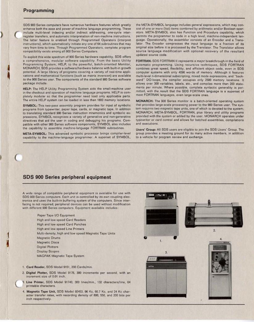
A wide range of compatible peripheral equipment is available for use with SDS 900 Series computers. Each unit is controlled by its own coupling electronics and uses the built-in buffering system of the computers. Since interfacing is not required, peripheral devices can be used without modification with different 900 Series computers. Equipment available includes:
Paper Tape I/O Equipment
High and low speed Card Readers
High and low speed Card Punches
High and low speed line Printers
Multi-density, high and low speed Magnetic Tape Units
Magnetic Drums
Magnetic Discs
Digital Plotters
Display Scopes
MAGPAK Magnetic Tape System
1. Card Reader, SDS Model 9151, 200 Cards/min.
2. Digital Plotter, SDS Model 9175, 300 increments per second, with an increment size of 0.01 inch .
'3. line Printer, SDS Model 91740, 300 lines/min ., 132 characters/line, 64 printable characters.
4. Magnetic Tape Unit, SDS Model 92453, 96 Kc, 66.7 Kc, and 24 Kc character transfer rates, with recording density of 800, 556, and 200 bits per inch respectively.
the META-SYMBOL language includes general expressions, which may consist of one or more (list) items combined by arithmetic and/or Boolean operators . META-SYMBOL also has Function and Procedure capability, which permits the programmer to code in a high level, machine- independent language. Operationally, the assembler consists of an Encoder and a Translator. The Encoder compresses the input language to a fraction of its original size before it is processed by the Translator. The Translator allows source language modification with optional recovery of the resultant updated source code.
FORTRAN: SDS FORTRAN II represents a major breakthrough in the field of automatic pro gra mming . Usi ng recursive techniques, SDS FORTRAN combines great speed , flexibility, and efficient object code, even in SDS computer systems with only 4096 words of memory. Although it features multi-leve l n-dimensional subscripting , mixed mode expressions, and "backward" DO-loops, the compiler occupies only 2500 memory locations. It allows over 300 variables, labels , etc., and compiles more than 200 statements per minute. Where possible, complete syntactic generality is permitted, with the /esult that the SDS FORTRAN language is a superset of most FORTRAN languages, even large-scale ones .
MONARCH: The 900 Series monitor is a batch-oriented operating system that provides large-scale processing power to the 900 Series user. The system requires two magnetic tape units, one of which is devoted to the system: MONARCH, META-SYMBOL, FORTRAN, plus library and utility programs provided with the system or added by the user. MONARCH operates under typewriter or card control and allows for batched assemblies, compilations and executions.
Users' Group: All SDS users are eligible to join the SDS Users' Group. The group provides a meeting ground for its many active members, in addition to a vehicle for program review and exchange.
2.
1. 4.
3.

50S 900 Series instruction format
This instruction word format for SDS 900 Series computers is:
R X INSTRUCTION CODE
A ADDRESS FIELD
o 2 3 4 5 6 7 8 9 10 11 12 13 14 15 16 17 18 19 20 21 22 23
Bit Position
o Function
Relative Address Bit-A "one" in this position causes the standard loading programs to add the assigned instruction location to the address field contents prior to actual storage. This bit position is not sensed by central processor decoding logic.
Index Register Bit-A "one" in this position causes the contents of positions 10-23 of the index register to be added to the address portion of the instruction prior to execution.
SDS 900 SERIES INSTRUCTION LIST
2-8
9
10-23
Instruction Code- The contents of these bit positions determine the operation to be performed. Bit position 2 is used with Programmed Operators and is considered a part of the " tag " field (0-2).
Indirect Address Bit-A "one" in this position causes the computer to interpret the contents of positions 10-23 (possibly modified by indexing) as the address of the memory location where the effective address of the instruction may be found . A "zero" causes the contents of positions 10-23 (possibly modified by indexing) to be interpreted as the effective address of the instruction.
Address -The contents of these pOSitions normally determine the memory address referenced by the instruction code. With the SDS 930, bit position 10 contains the Memory Extension Bit that controls addressing above location 8,191 .
SOS 910 SOS 920 SOS 930 SOS 910 SOS 920 SOS 930 1 cycle = 1 cycle = 1 cycle = 1 cycle = 1 cycle = 1 cycle =
Instruction 8 !,sec. 8 !,sec. 1.925 !, sec. Instruction 8 !,sec. 8 !,sec. 1.925 !'sec.
LOAD-STORE LDA LOAD A 2 2 2 CLR CLEAR AB STA STORE A 3 3 3 CAB COPY A INTO B LDB LOAD B 2 2 2 CBA COpy B INTO A STB STORE B 3 3 3 XAB EXCHANGE A AND B LDX LOAD INDEX 2 2 2 BAC COPY B INTO A, CLEAR B STX STORE INDEX 3 3 3 ABC COpy A INTO B, CLEAR A XMA EXCHANGE M AND A 3 3 CXA COpy INDEX INTO A
CAX COpy A INTO INDEX ARITHMETIC XXA EXCHANGE INDEX AND A
ADD ADD M to A 2 2 2 CBX COpy B INTO INDEX ADC ADD WITH CARRY 2 2 CXB COpy INDEX INTO B ADM ADD A to M 3 3 XXB EXCHANGE INDEX AND B MIN MEMORY INCREMENT 3 3 3 STE STORE EXPONENT SUB SUBTRACT M FROM A 2 2 2 LDE LOAD EXPONENT SUC SUBTRACT WITH CARRY 2 2 XEE EXCHANGE EXPONENTS MUL MULTIPLY 4 4 CNA COpy NEGATIVE INTO A MUS MULTIPLY STEP 2 DIV DIVIDE 28 10 SHIFT DIS DIVIDE STEP 2 RSH RIGHT SHIFT AB Even
2+N 2+N 2-7 BRANCH-SKIP 2
BRU BRANCH UNCONDITIONALLY 1 1 Odd BRX INCREMENT INDEX 1,2 1,2 1,2 2+N+1
AND BRANCH --BRM MARK PLACE AND BRANCH 2 2 2
2
BRR RETURN BRANCH 2 2 2 RCY RIGHT CYCLE AB 2+N See RSH 2-7
SKS SKIP IF SIGNAL NOT SET 1,2 1,2 2,3 LSH LEFT SH IFT AB 2+N See RSH 2-7
SKE SKIP IF A EQUALS M 2,3 2,3 LCY LEFT CYCLE AB 2+N See RSH 2-7
SKG SKIP IF A GREATER THAN M 2,3 2,3 2,3 NOD NORMALIZE AND DECREMENT X 2+N See RSH 2-7
SKR REDUCE M, SKIP IF NEGATIVE 3 3 SKM SKIP IF A=M ON B MASK 3 3 CONTROL
SKN SKIP IF M NEGATIVE 2,3 2,3 2,3 HLT HALT 1
SKA SKIP IF M and A DO NOT 2,3 2,3 2,3 NOP NO OPERATION 1 1
COMPARE ONES EXU EXECUTE 1 1 1
SKB SKIP IF M and B DO NOT 2,3 2,3 EAX COpy EFFECTIVE ADDRESS 2 2 2
COMPARE ONES INTO INDEX REGISTER
SKD DIFFERENCE EXPONENTS 2,3 2,3 AND SKIP INPUT/OUTPUT
MIW MINTO W BUFFER WHEN READY 2+wait 2+wait 2+wait LOGICAL WIM W BUFFER INTO M WHEN READY 3+wait 3+wait 3+wait
ETR EXTRACT 2 2 2 MIY MINTO Y BUFFER WHEN READY 2+wait 2+wait 2+wait MRG MERGE 2 2 2 YIM Y BUFFER INTO M WHEN READY 3+wait 3+wait 3+wait EOR EXCLUSIVE OR 2 2 2 POT PARALLEL OUTPUT 3+wait 3+wait 3+wait
PIN PARALLEL INPUT 4+wait 4+wait 4+wait REGISTER CHANGE EOM ENERG IZE OUTPUT M 1 1 1
CLA CLEAR A EOD ENERGIZE OUTPUT TO DIRECT CLB CLEAR B ACCESS CHANNEL

SOS 900 Series systems applications
SDS 900 Series computers are easily integrated into a wide range of realtime data acquisition and control systems. SDS offers a complete line of all-silicon systems building blocks, including: analog-to-digital and digitalto-analog converters, amplifiers, multiplexers, and digital logic circuit mod-
Data acquisition system
.' ).-" , ~ ·t";'(··};-'-~
11:0
II.!"'" --'
--
Analog signals of various sorts are multiplexed, under program control, into the analog-to-digital converter. The computer reads the converter output, together with other direct digital inputs, and performs the following functions:
1. Performs zero and full-scale corrections
2. Converts data to engineering units
3. Formats converted data for recording on magnetic tape, and displays selected data points
Typical numbers of inputs that can be processed by the three computers reo SDS 910: 1500jsec.; SDS 920: 3000jsec.; SDS 930: 12,000jsec. These
rates are typical and may vary with specific system requirements.
ules. These devices are all compatible with SDS 900 Series computers and peripheral equipment so that the construction of a complex system simply requires the inter-connecting of the various elements, without expensive design engineering. Some typical systems are illustrated below.
-,,,;-
-- , ti#1
~
I II III

REGIONAL OFFICES
Northeast 125-10 Queens Blvd. Kew Gardens, N. Y. (212) Liggett 4-9898
Southeast 1145 Nineteenth St., N.W. Washington, D. C. (202) 337-6838
Midwest 3150 Des Plaines Ave. Des Plaines, III. (312) 824-8147
West 1649 Seventh St. Santa Monica, Calif. (213) UPton 0-5471
DISTRICT OFFICES
69 Hickory Dr. Newton Lower Falls, Mass. (617) 899-4700
SCIENTIFIC DATA SYSTEMS
35 Camelot Dr. Plymouth Meeting, Pa. (215) TAylor 8-8074
One Parkway Center 875 Greentree Rd. Pittsburgh, Pa. (412) 921-3640
Holiday Office Center Huntsville, Ala. (205) 881-5746
16 South Bumby St. Orlando, Fla. (305) 425-4611
3334 Richmond Ave. Houston, Texas (713) JAckson 6-2693
Sunnyvale Office Center 505 West Olive Ave. Sunnyvale, Calif. (408) 736-9193
Fountain Professional Bldg. 9000 Menaul Blvd., N.E. Albuquerque, N. Mex.
III Scientific Data Systems 1964 Printed in U.S.A.- SDS 9800328
FOREIGN REPRESENTATIVES
Europe CECIS 14 Rue de la Baume Paris 8e, France
Canada INSTRONICS, Ltd. P.O. Box 100 Stittsville OntariO, Canada
Japan F. Kanematsu & Co. Inc. Central P.O. Box 141 New Kaijo Bldg. Marunouchi Tokyo, Japan
Australia RACAL Pty. Ltd. 5 Ridge St. N. Sydney NSW, Australia
I