scientific and technological innovations in the
TRANSCRIPT
Advances in Applied Sciences 2018; 3(6): 65-78
http://www.sciencepublishinggroup.com/j/aas
doi: 10.11648/j.aas.20180306.11
ISSN: 2575-2065 (Print); ISSN: 2575-1514 (Online)
Scientific and Technological Innovations in the Reprocessing Metal-Containing Industrial Waste and Industrial Waste of Polymeric Materials by Metallurgical Methods
Aliaxandr Ivanavich Harast, Elena Valeryevna Kryvonosova
Department of Material Science and Engineering of Technical Systems, Belarusian State Technological University, Minsk, Belarus
Email address:
To cite this article: Aliaxandr Ivanavich Harast, Elena Valeryevna Kryvonosova. Scientific and Technological Innovations in the Reprocessing Metal-Containing
Industrial Waste and Industrial Waste of Polymeric Materials by Metallurgical Methods. Advances in Applied Sciences.
Vol. 3, No. 6, 2018, pp. 65-78. doi: 10.11648/j.aas.20180306.11
Received: December 27, 2018; Accepted: January 29, 2019; Published: February 26, 2019
Abstract: The paper studies the mechanism of using baling charge and modifying materials, including metal-containing
industrial waste and man made waste of polymer products introduced as bales into the melt. This process is accompanied by
pyrolysis of polymers and homolytic cleavage of bonds with hydrogen and carbon atoms (hydrocarbon radicals) formation,
reducing iron from new charge materials and other metals, from cheap additives that provide modification, including the
centers formed in the melt as a result of chemical reactions. The method secures technological strength and indestructibility of
bales during transportation, heating and melting.
Keywords: Iron-Carbon Alloys, Alloying, Industrial Metal-Containing Waste, Structure Formation,
Material Balance of Melting, Morphology of Non-Metallic Inclusions
1. Introduction
Due to the gradual depletion of the exploited iron ore
deposits, decrease of scrap metal collection, increase of the
cast iron cost and railway fares for its delivery, the
metallurgy had to search for alternative materials [1].
A number of technological processes are accompanied by
formation of a significant amount of metal-containing waste
[1-4], mainly as oxides (scale, rust, sludge, grinding scrapes,
wastes of facing materials, etc.). When using known reducing
agents (carbon as coke and graphite dust, powdered
charcoal), a sufficient degree of metal extraction is not
provided [5-6]. The described technology was not widely
used in the smelting of iron-carbon alloys. This is due to the
lack of effective reducing agents and insufficient reactivity of
carbon and silicon to a number of oxides. The degree of
alloying elements recovery from slag is determined by the
reaction of alloying elements with iron oxides.
Being pioneered at the Belarusian state technological
University [7-8] the methods of iron and steel smelting
suggest using waste polymeric materials from chemical
compounds for metals reduction and providing the
reprocessing of metal-containing waste by metallurgical
methods [9-11]. It should be noted that about 50 billion tons
of plastic have been produced since 1950s, 80% of which is
not reprocessed and is diposed of at landfills (about 50
million tons per year).
A comprehensive solution to the problem involves the use
and reprocessing of industrial waste and semi-finished
products related to mechanical engineering [1, 12] at all
stages of metallurgical processing: melting of baling charge
materials of metal-containing industrial waste, which are
mainly in the form of oxides: oxides scale, rust, sludge,
grinding scrapes, including organic pollutants, wastes of
facing materials, waste catalysts of chemical, petrochemical,
mineral fertilizers production industries, which contain
Al2O3, SiO2, CaO as well as nickel, molybdenum, cobalt,
copper, chromium and tungsten oxides; semi-finished
products related to mechanical engineering industries
(titanium oxides, vanadium and other elements used as raw
materials in the glass industry); non-recoverable high-
polymer compounds (not prone to coke formation during
thermal destruction (polyolefins, aliphatic polyamides), or
prone to coke formation (polyphenylenes, polyamides,
66 Aliaxandr Ivanavich Harast and Elena Valeryevna Kryvonosova: Scientific and Technological Innovations in the Reprocessing
Metal-Containing Industrial Waste and Industrial Waste of Polymeric Materials by Metallurgical Methods
polybenzimidazoles), as well as non-recoverable elastomers
(silicone, acrylic rubbers, rubber based on ethylene
propylene, chloroprene, polysulfide rubbers, butyl rubber,
polyurethane), including rubber products containing 15-35%
of textile or metal reinforcing materials containing
chemically bound or structurally free carbon [1, 7-8];
finishing melts by direct, direct surface alloying methods and
modification, provided by reducing metals by atomic
hydrogen and carbon, formed during the homolytic cleavage
of bonds in the pyrolysis of polymers introduced in bales
together with metal-containing waste, in the melt, creating a
reducing medium and providing modification [1, 10-11, 13],
accompanied by chemical interaction of the components of
additives with individual elements of the crystallizing
substance, including the centers, formed in the melt.
The proposed method is aimed at creating a fundamentally
new technology of metallurgical processing of iron-
containing industrial waste (scale, iron-containing dust,
sludge, iron-containing sludge) by baling them together with
man-made waste polymers, using as reducing agents of the
conpounds formed during pyrolysis of polymers and
homolytic cleavage of bonds. This technology will save
material and energy resources, reduce harmful emissions and
improve the quality characteristics of alloys.
2. Composition and Structure of Original
Materials
Iron-containing man-made waste
The investigation of scale and other components of the
bales was carried out by scanning electron microscopy with
microscope JSM–5610LV (firm JEOL, Japan) with a system
of electron probe energy dispersive x – ray analysis. The
microcomposition of inclusions was determined by the
method of electron – probe EDX analysis on the detector IED
2201.
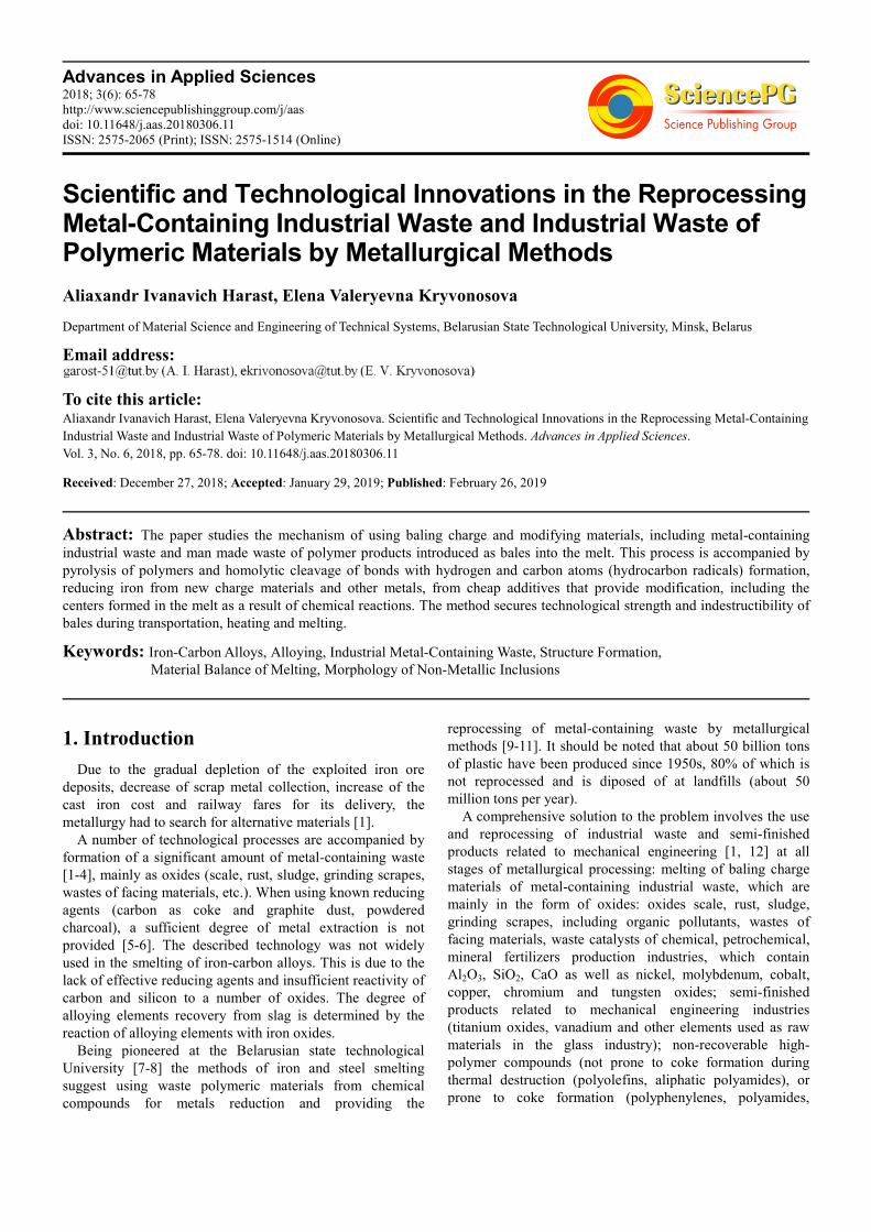
The scale is presented by exfoliated and fragmented flakes
up to 2 mm thick (figure 1).
Figure 1. Appearance of lump scale from steel feed after reheating furnace.
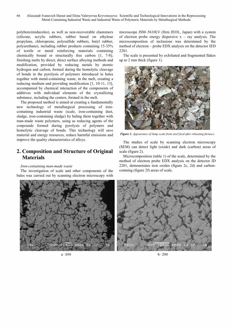
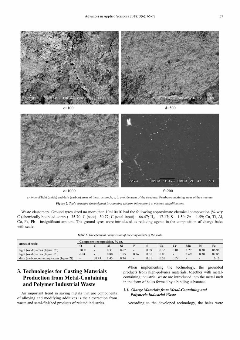
The studies of scale by scanning electron microscopy
(SEM) can detect light (oxide) and dark (carbon) areas of
scale (figure 2).
Microcomposition (table 1) of the scale, determined by the
method of electron probe EDX analysis on the detector ID
2201, demonstrates iron oxides (figure 2c, 2d) and carbon-
containg (figure 2f) areas of scale.
Advances in Applied Sciences 2018; 3(6): 65-78 67
a - type of light (oxide) and dark (carbon) areas of the structure; b, c, d, e-oxide areas of the structure; f-carbon-containing areas of the structure.
Figure 2. Scale structure (investigated by scanning electron microscopy) at various magnifications.
Waste elastomers. Ground tyres sized no more than 10×10×10 had the following approximate chemical composition (% wt):
C (chemically bounded comp.)– 35.70; C (soot)– 30.77; C (total input) – 66.47; H2 – 17.17; S – 1.50; Zn – 1.59; Cu, Ti, Al,
Co, Fe, Pb – insignificant amount. The ground tyres were introduced as reducing agents in the composition of charge bales
with scale.
Table 1. The chemical composition of the components of the scale.
areas of scale Component composition, % wt.
O C Al Si P S Ca Cr Mn Ni Fe
light (oxide) areas (figure. 2c) 10.11 - 0.31 0.62 - 0.09 0.35 0.01 1.27 0.30 86.96
light (oxide) areas (figure. 2d) 6.74 - 0.80 1.55 0.26 0.01 0.80 - 1.69 0.30 87.85
dark (carbon-containing) areas (figure 2f) - 80.43 1.45 0.34 - 0.31 0.52 0.29 - - 16.16
3. Technologies for Casting Materials
Production from Metal-Containing
and Polymer Industrial Waste
An important trend in saving metals that are components
of alloying and modifying additives is their extraction from
waste and semi-finished products of related industries.
When implementing the technology, the grounded
products from high-polymer materials, together with metal-
containing industrial waste are introduced into the metal melt
in the form of bales formed by a binding substance.
3.1. Charge Materials from Metal-Containing and
Polymeric Industrial Waste
According to the developed technology, the bales were
68 Aliaxandr Ivanavich Harast and Elena Valeryevna Kryvonosova: Scientific and Technological Innovations in the Reprocessing
Metal-Containing Industrial Waste and Industrial Waste of Polymeric Materials by Metallurgical Methods
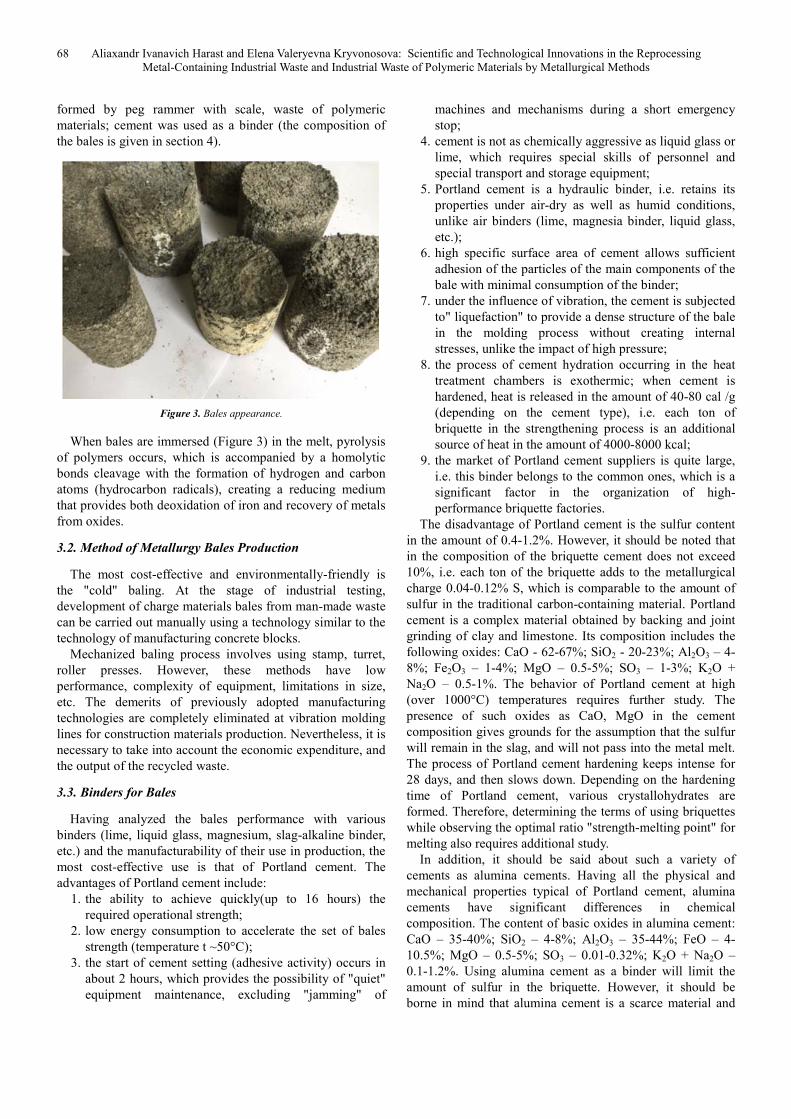
formed by peg rammer with scale, waste of polymeric
materials; cement was used as a binder (the composition of
the bales is given in section 4).
Figure 3. Bales appearance.
When bales are immersed (Figure 3) in the melt, pyrolysis
of polymers occurs, which is accompanied by a homolytic
bonds cleavage with the formation of hydrogen and carbon
atoms (hydrocarbon radicals), creating a reducing medium
that provides both deoxidation of iron and recovery of metals
from oxides.
3.2. Method of Metallurgy Bales Production
The most cost-effective and environmentally-friendly is
the "cold" baling. At the stage of industrial testing,
development of charge materials bales from man-made waste
can be carried out manually using a technology similar to the
technology of manufacturing concrete blocks.
Mechanized baling process involves using stamp, turret,
roller presses. However, these methods have low
performance, complexity of equipment, limitations in size,
etc. The demerits of previously adopted manufacturing
technologies are completely eliminated at vibration molding
lines for construction materials production. Nevertheless, it is
necessary to take into account the economic expenditure, and
the output of the recycled waste.
3.3. Binders for Bales
Having analyzed the bales performance with various
binders (lime, liquid glass, magnesium, slag-alkaline binder,
etc.) and the manufacturability of their use in production, the
most cost-effective use is that of Portland cement. The
advantages of Portland cement include:
1. the ability to achieve quickly(up to 16 hours) the
required operational strength;
2. low energy consumption to accelerate the set of bales
strength (temperature t ~50°C);
3. the start of cement setting (adhesive activity) occurs in
about 2 hours, which provides the possibility of "quiet"
equipment maintenance, excluding "jamming" of
machines and mechanisms during a short emergency
stop;
4. cement is not as chemically aggressive as liquid glass or
lime, which requires special skills of personnel and
special transport and storage equipment;
5. Portland cement is a hydraulic binder, i.e. retains its
properties under air-dry as well as humid conditions,
unlike air binders (lime, magnesia binder, liquid glass,
etc.);
6. high specific surface area of cement allows sufficient
adhesion of the particles of the main components of the
bale with minimal consumption of the binder;
7. under the influence of vibration, the cement is subjected
to" liquefaction" to provide a dense structure of the bale
in the molding process without creating internal
stresses, unlike the impact of high pressure;
8. the process of cement hydration occurring in the heat
treatment chambers is exothermic; when cement is
hardened, heat is released in the amount of 40-80 cal /g
(depending on the cement type), i.e. each ton of
briquette in the strengthening process is an additional
source of heat in the amount of 4000-8000 kcal;
9. the market of Portland cement suppliers is quite large,
i.e. this binder belongs to the common ones, which is a
significant factor in the organization of high-
performance briquette factories.
The disadvantage of Portland cement is the sulfur content
in the amount of 0.4-1.2%. However, it should be noted that
in the composition of the briquette cement does not exceed
10%, i.e. each ton of the briquette adds to the metallurgical
charge 0.04-0.12% S, which is comparable to the amount of
sulfur in the traditional carbon-containing material. Portland
cement is a complex material obtained by backing and joint
grinding of clay and limestone. Its composition includes the
following oxides: CaO - 62-67%; SiO2 - 20-23%; Al2O3 – 4-
8%; Fe2O3 – 1-4%; MgO – 0.5-5%; SO3 – 1-3%; K2O +
Na2O – 0.5-1%. The behavior of Portland cement at high
(over 1000°C) temperatures requires further study. The
presence of such oxides as CaO, MgO in the cement
composition gives grounds for the assumption that the sulfur
will remain in the slag, and will not pass into the metal melt.
The process of Portland cement hardening keeps intense for
28 days, and then slows down. Depending on the hardening
time of Portland cement, various crystallohydrates are
formed. Therefore, determining the terms of using briquettes
while observing the optimal ratio "strength-melting point" for
melting also requires additional study.
In addition, it should be said about such a variety of
cements as alumina cements. Having all the physical and
mechanical properties typical of Portland cement, alumina
cements have significant differences in chemical
composition. The content of basic oxides in alumina cement:
CaO – 35-40%; SiO2 – 4-8%; Al2O3 – 35-44%; FeO – 4-
10.5%; MgO – 0.5-5%; SO3 – 0.01-0.32%; K2O + Na2O –
0.1-1.2%. Using alumina cement as a binder will limit the
amount of sulfur in the briquette. However, it should be
borne in mind that alumina cement is a scarce material and
Advances in Applied Sciences 2018; 3(6): 65-78 69
its price is 5 times higher than that of Portland cement.
Considering the binders for the production of metallurgical
briquettes, it is important to mention the slag-alkali binder. It
would seem that the use of slag as a binder for metallurgical
briquettes is the most appropriate one. However, sulfur is
present in approximately equal amounts in the composition
of slag as well as in Portland cement. But the main reason
that limits the use of slag as a binder is the high energy costs
for slag activation. Slags are active if their specific surface
area is more than 4500 cm2/g. If compared, the duration of
slag grinding is 2-2.5 times longer than the duration of
cement clinker grinding.
Taking into account all the above, we can conclude about
the advantages of using Portland cement as a binder in the
production of metallurgical briquettes, which does not
exclude the use of other types of binders (lime, liquid glass,
magnesium, slag-alkali binder, etc.) for solving special
problems.
4. The Behavior of the Melt Components When the Bales of Iron-Containing Waste
and Waste Elastomers (Grouded Tyres) Are Introduced
4.1. The Composition of the Charge in the Smelting of Cast Iron with the Introduced iron-Containing Waste and Waste
Elastomers (Grounded Tires) Bales
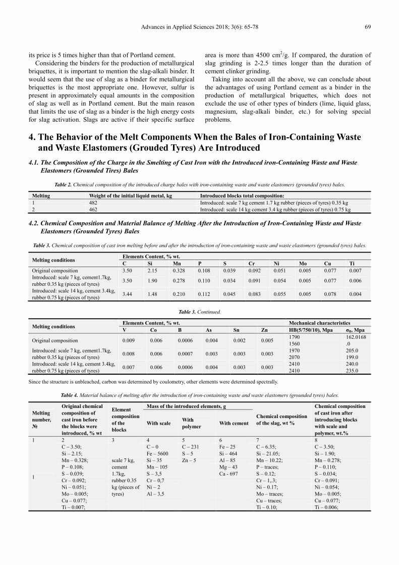
Table 2. Chemical composition of the introduced charge bales with iron-containing waste and waste elastomers (grounded tyres) bales.
Melting Weight of the initial liquid metal, kg Introduced blocks total composition:
1 482 Introduced: scale 7 kg cement 1.7 kg rubber (pieces of tyres) 0.35 kg
2 462 Introduced: scale 14 kg cement 3.4 kg rubber (pieces of tyres) 0.75 kg
4.2. Chemical Composition and Material Balance of Melting After the Introduction of Iron-Containing Waste and Waste
Elastomers (Grounded Tyres) Bales
Table 3. Chemical composition of cast iron melting before and after the introduction of iron-containing waste and waste elastomers (grounded tyres) bales.
Melting conditions Elements Content, % wt.
C Si Mn P S Cr Ni Mo Cu Ti
Original composition 3.50 2.15 0.328 0.108 0.039 0.092 0.051 0.005 0.077 0.007
Introduced: scale 7 kg, cement1.7kg,
rubber 0.35 kg (pieces of tyres) 3.50 1.90 0.278 0.110 0.034 0.091 0.054 0.005 0.077 0.006
Introduced: scale 14 kg, cement 3.4kg,
rubber 0.75 kg (pieces of tyres) 3.44 1.48 0.210 0.112 0.045 0.083 0.055 0.005 0.078 0.004
Table 3. Continued.
Melting conditions Elements Content, % wt. Mechanical characteristics
V Co B As Sn Zn HB(5/750/10), Мpa σВ, Мpа
Original composition 0.009 0.006 0.0006 0.004 0.002 0.005 1790
1560
162.0168
.0
Introduced: scale 7 kg, cement1.7kg,
rubber 0.35 kg (pieces of tyres) 0.008 0.006 0.0007 0.003 0.003 0.003
1970
2070
205.0
199.0
Introduced: scale 14 kg, cement 3.4kg,
rubber 0.75 kg (pieces of tyres) 0.007 0.006 0.0006 0.004 0.003 0.003
2410
2410
240.0
235.0
Since the structure is unbleached, carbon was determined by coulometry, other elements were determined spectrally.
Table 4. Material balance of melting after the introduction of iron-containing waste and waste elastomers (grounded tyres) bales.
Melting
number,
№
Original chemical
composition of
cast iron before
the blocks were
introduced, % wt
Element
composition
of the
blocks
Mass of the introduced elements, g
Chemical composition
of the slag, wt %
Chemical composition
of cast iron after
introducing blocks
with scale and
polymer, wt.%
With scale With
polymer With cement
1 2 3 4 5 6 7 8
1
C – 3.50;
scale 7 kg,
cement
1.7kg,
rubber 0.35
kg (pieces of
tyres)
C – 0 C – 231 Fe – 25 C – 6.35; C – 3.50;
Si – 2.15; Fe – 5600 S – 5 Si – 464 Si – 21.05; Si – 1.90;
Mn – 0.328; Si – 35 Zn – 5 Al – 85 Mn – 10.22; Mn – 0.278;
P – 0.108; Mn – 105
Mg – 43 P – traces; P – 0.110;
S – 0.039; S – 3,5
Ca - 697 S – 0.12; S – 0.034;
Cr – 0.092; Cr – 0,7
Cr – 1,.3; Cr – 0.091;
Ni – 0.051; Ni – 2
Ni – 0.17; Ni – 0.054;
Mo – 0.005; Al – 3,5
Mo – traces; Mo – 0.005;
Cu – 0.077;
Cu – traces; Cu – 0.077;
Ti – 0.007;
Ti – 0.10; Ti – 0.006;
70 Aliaxandr Ivanavich Harast and Elena Valeryevna Kryvonosova: Scientific and Technological Innovations in the Reprocessing
Metal-Containing Industrial Waste and Industrial Waste of Polymeric Materials by Metallurgical Methods
Melting
number,
№
Original chemical
composition of
cast iron before
the blocks were
introduced, % wt
Element
composition
of the
blocks
Mass of the introduced elements, g
Chemical composition
of the slag, wt %
Chemical composition
of cast iron after
introducing blocks
with scale and
polymer, wt.%
With scale With
polymer With cement
V – 0.009;
V – traces; V – 0.008;
Co – 0.006;
Co – traces; Co – 0.006;
B – 0.0006;
B – none; B – 0.0007;
As – 0.004;
As – traces; As – 0.003;
Sn – 0.002;
Sn – traces; Sn – 0.003;
Zn – 0.005
Zn – traces; Zn – 0.003
O – 31.51;
Al – 2.21;
Na – 0.43;
Mg – traces;
K – 0.17;
Ca – 7.00;
Pb – 0.22;
N – none;
Fe – 27.26
2
C – 3.50;
scale 14 kg,
cement
3.4kg,
rubber 0.75
kg (pieces of
tyres) кг
C – 0 C – 495 Fe – 50 C – 8.83; C – 3.44;
Si – 1.90; Fe – 11200 S – 10 Si – 928 Si – 19.11; Si – 1.48;
Mn – 0.278; Si – 70 Zn – 10 Al – 170 Mn – 4.49; Mn – 0.210;
P – 0.110; Mn – 210
Mg – 86 P – 0.02; P – 0.112;
S – 0.034; S – 7
Ca - 1394 S – traces; S – 0.045;
Cr – 0.091; Cr –0,14
Cr – 0.07; Cr – 0.083;
Ni – 0.054; Ni – 4
Ni – traces; Ni – 0.055;
Mo – 0.005; Al – 7
Mo – traces; Mo – 0.005;
Cu – 0.077;
Cu – traces; Cu – 0.078;
Ti – 0.006;
Ti – traces; Ti – 0.004;
V – 0.008;
V – 0.09; V – 0.007;
Co – 0.006;
Co – 0.38; Co – 0.006;
B – 0,0007;
B – none; B – 0.0006;
As – 0.003;
As – 0.94; As – 0.004;
Sn – 0.003;
Sn – 0.40; Sn – 0.003;
Zn – 0.003
Zn – traces; Zn – 0.003
O – 34.60;
Al – 2.09;
Na – 0.11;
Mg – traces;
K – 0.15;
Ca – 6.55;
Pb – traces;
N – none;
Fe – 27.26
The nature of changes in the slag microcomposition,
structure and density after the bales wth iron-containing
waste and waste elastomers (grounded tyres) were
introduced.
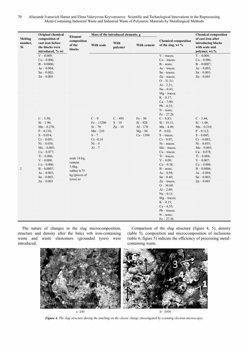
Comparison of the slag structure (figure 4, 5), density
(table 5), composition and microcomposition of inclusions
(table 6, figure 5) indicate the efficiency of processing metal-
containing waste.
Figure 4. The slag structure during the smelting on the classic charge (investigated by scanning electron microscopy).
Advances in Applied Sciences 2018; 3(6): 65-78 71
A significant decrease in the slag density (table 4) is
explained by the high reducing ability of the polymer
pyrolysis products. In all components of the initial slag, the
concentration of iron is 2-3 times higher than its
concentration in melts with the introduction of charge bales
from scale, cement, and polymers are introduced (table 5). In
this case, the dynamics of reducing concentration of metal
elements (Si from 21.05% to 19.11%, Mn from 10.22% to
4.49%, Cr from 1.13% to 0.07%, Ni from 0.17% to traces, Ti
from 0.10% to traces, Al from 2.21 to 2.09%, Na from 0.43%
to 0.11%, Pb from 0.22% to traces) in the slag; the volume of
introduced charge is increased (Table3).
The introduction of charge materials, including scale,
cement and polymer, the iron is reduced and it transfers to
the cast iron (table 3).
The density of the resulting slag during the smelting of
cast iron on the classic charge and using new charge
materials is completely different (table 5).
Table 5. The density of the original smelting on the classic charge and using new charge materials.
Smelting conditions smelting on the classic charge Introduced: scale 7 kg, cement 1.7kg,
rubber 0.35 kg (pieces of tyres)
Introduced: scale 14 kg, cement 3.4kg,
rubber 0.75 kg (pieces of tyres)
Slag density, g/cm3 3.77 2.52 1.01
Table 6. Chemical composition of non-metallic slag inclusions after introducing bales of scale and elastomers waste (grounded tyres) into the melt.
Mass fraction of the
introduced
additive, % wt.
Position of
Inclusion
Contents of elements, % wt
C O Si Mn S P Cr V Ti Cu Ni Mo
Not introduced
1 (figure 4b) 24.27 1.95 1.69 0.12 0.17
2 (figure 4b) 6.01 23.73 4.03 1.27 0.24 0.30 0.06
3 (figure 4b) 4.62 41.55 28.08 4.32 0.29 0.06 0.19 0.51
4 (figure 4b) 39.33 22.09 12.92 0.98 0.20 0,21 0.16
5 (figure 4b) 4.32 21.29 0.68 16.67 0.04 0.11
6 (figure 4b) 0.86 24,02 2.10 2.61 0.03 0.19
7 (figure 4b) 23.62 1.23 1.44 0.11 0.04 0.50 0.03
Introduced as part of
charge bales: scale 7
kg, cement 1.7kg,
rubber 0.35 kg
(pieces of tyres)
average (figure 5a) 6.35 31.51 13.13 10.22 0.12 1.13 0.10 0.17
1 (figure 5b) 38,87 9.10 0.60 0.73 0.29 0.61
2 (figure 5b) 4.29 27.31 7.13 10.81 0.09 0.21 0.61 0.32
3 (figure 5b) 6.54 27.53 8.02 2.11 0.62 0.17 0.87 0.16 0.46 5.12 0.61
4 (figure 5b) 3.09 27.68 4.61 7.18 0.06 0.05 15.38 0.35 0.40 0.12 0.14
5 (figure 5b) 11.81 31.20 14.74 4.43 0.19 1.43 0.29 0.28 1.09
6(figure 5b) 9.43 32.55 14.87 6.10 0.12 1.92 0.13 0.11 0.89
Introduced as part of
charge bales: scale 14
kg, cement 3.4kg,
rubber 0.75 kg
(pieces of tyres)
average (figure 5c) 8.83 34.60 19.11 4.49 0.02 0.07 0.09
1 (figure 5d) 12,62 39.54 27.05 1.81 0.07 0.01 0.24 0.01 0.24
2 (figure 5d) 4.01 35.09 17.84 5.33 0.12 0.65 0.27 0.22
1 (figure 5e) 39.06 22.59 3.57
2 (figure 5e) 301 34.45 17.99 4.70 0.18 0.21 0.91 0.12 0.37 0.24 0.55
Table 6. Continued.
Mass fraction of
the introduced
additive,% wt
Position of
Inclusion
Contents of elements, % wt
Al Na Mg K Ca Co Zn As Sn Pb N Fe
Not introduced
1 (figure 4b) 1.05 0.60 0.16 0.88 69.11
2 (figure 4b) 1.51 0.27 3.85 58.73
3 (figure 4b) 5.33 1.10 0.13 2.68 8.54 2.59
4 (figure 4b) 5.04 1.12 0.14 0.73 1.28 13.08
5 (figure 4b) 0.25 0.07 0.03 3.18 53.36
6 (figure 4b) 0.77 0.26 0.05 0.31 68.80
7 (figure 4b) 0.53 0.22 0.02 72.26
Introduced as part
of charge bales:
scale 7 kg, cement
1.7kg, rubber 0.35
kg (pieces of tyres)
average (figure 5a) 2.21 0.43 0.17 7.00 0.22 27.26
1 (figure 5b) 5.90 0.14 0.12 8.14 0.21 0.79 0.21 34.29
2 (figure 5b) 0.75 0.45 0.06 5.70 0.47 0.04 41.76
3 (figure 5b) 0.87 0.10 1.10 0.52 0.17 0.03 0.26 44.73
4 (figure 5b) 0.87 0.28 0.22 1.85 0.10 0.36 37.25
5 (figure 5b) 1.77 0.44 0.06 3.56 0.50 1.17 0.36 26.67
6(figure 5b) 2.55 1.03 0.97 0.07 4.43 24.82
Introduced as part
of charge bales:
scale 14 kg, cement
3.4kg, rubber 0.75
kg (pieces of tyres)
average (figure 5c) 2.09 0.11 0.11 0.15 6.55 0.38 0.94 0.40 21.78
1 (figure 5d) 2.80 0.52 5.81 0.36 8.91
2 (figure 5d) 2.12 0.34 0.30 6.02 0.24 0.54 0.09 26.84
1 (figure 5e) 2.37 7.83 24.58
2 (figure 5e) 2.51 0.11 6.59 6.68 21.14
72 Aliaxandr Ivanavich Harast and Elena Valeryevna Kryvonosova: Scientific and Technological Innovations in the Reprocessing
Metal-Containing Industrial Waste and Industrial Waste of Polymeric Materials by Metallurgical Methods
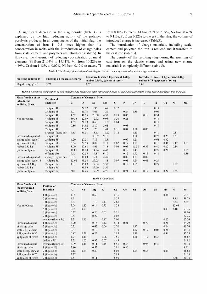
Figure 5. Slag structure (investigated by scanning electron microscopy).
a, b-introduced as part of charge bales: 7 kg scale, 1.7 kg cement, 0.35 kg rubber (pieces of tyres); c, d, e-introduced as part of charge bales: 14 kg of scale, 3.4
kg of cement, 0.75 kg of rubber (pieces of tyres).
5. Processes of Structure Formation in
Cast Iron When Scale Is Used in
Charge
The structure of cast iron was studied according to the
national standard (GOST) 3443-87. The structure of cast iron
was determined by graphite and metal base. When graphite is
defined, the following parametres are assessed: shape,
distribution, size and number of graphite inclusions. When
the metal base is defined, the following parametres are
assessed: structure type, shape of pearlite, amount of pearlite
and ferrite, dispersion of pearlite.
The study of graphite was carried out on a non-etched
metallographic sample, and metal base – on the
metallographic sample after etching. The following reagent
was used to etch the surface sample: 4 ml HNO3 (density 1.4
g/cm3) and 96 ml ethyl alcohol.
To determine the structure of cast iron, the sections were
examined under a microscope at the following magnifications:
1. the overall structure was increased 10 to 200 times;
Advances in Applied Sciences 2018; 3(6): 65-78 73
2. the shape, distribution, inclusion size, and graphite
amount was increased 100 times;
3. the metal base type – at 500 times magnification;
4. the amount of pearlite and ferrite – at 100 times
magnification;
5. the dispersion of lamellar pearlite − at 500 times
magnification.
The structure of cast iron was analyzed according to the
national standard (GOST) 3443-87 and compared visually to
the structure that is visible in the microscope and the
structure of an appropriate scale.
When the structure formation processes after introducing
the bales of iron-containing waste and polymer waste were
studied, the task of finishing the metal composition to meet
the requirements of technological conditions for specific
castings was not set.
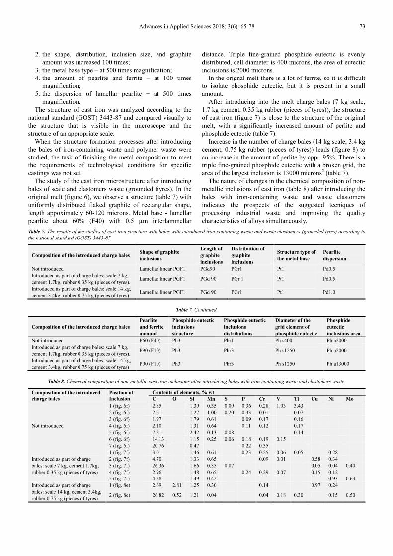
The study of the cast iron microstructure after introducing
bales of scale and elastomers waste (grounded tiyres). In the
original melt (figure 6), we observe a structure (table 7) with
uniformly distributed flaked graphite of rectangular shape,
length appoximately 60-120 microns. Metal base - lamellar
pearlite about 60% (F40) with 0.5 µm interlammellar
distance. Triple fine-grained phosphide eutectic is evenly
distributed, cell diameter is 400 microns, the area of eutectic
inclusions is 2000 microns.
In the orignal melt there is a lot of ferrite, so it is difficult
to isolate phosphide eutectic, but it is present in a small
amount.
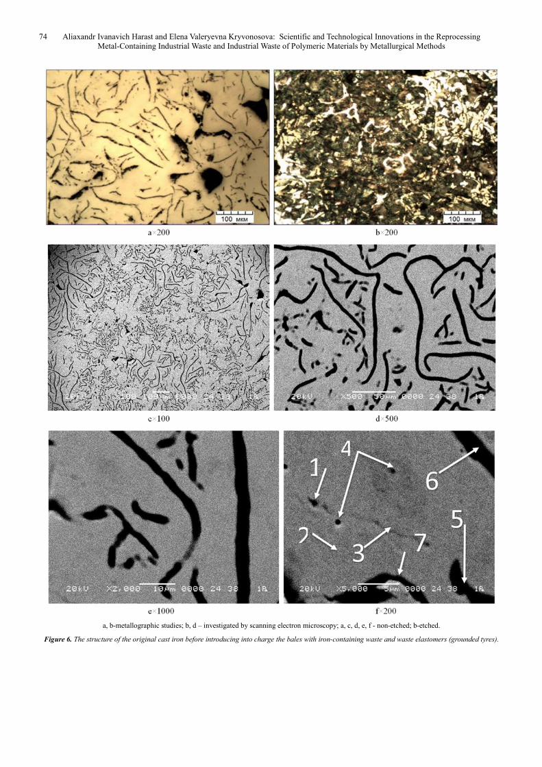
After introducing into the melt charge bales (7 kg scale,
1.7 kg cement, 0.35 kg rubber (pieces of tyres)), the structure
of cast iron (figure 7) is close to the structure of the original
melt, with a significantly increased amount of perlite and
phosphide eutectic (table 7).
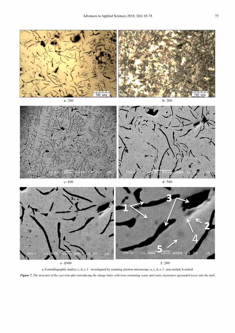
Increase in the number of charge bales (14 kg scale, 3.4 kg
cement, 0.75 kg rubber (pieces of tyres)) leads (figure 8) to
an increase in the amount of perlite by appr. 95%. There is a
triple fine-grained phosphide eutectic with a broken grid, the
area of the largest inclusion is 13000 microns2 (table 7).
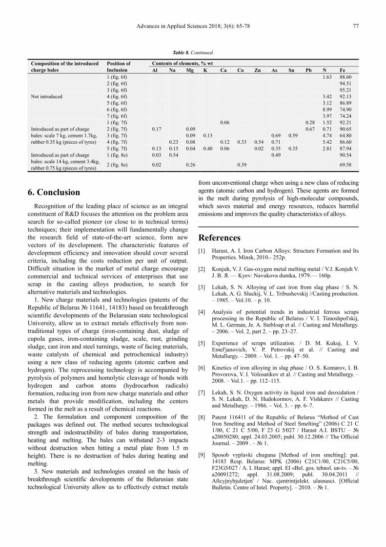
The nature of changes in the chemical composition of non-
metallic inclusions of cast iron (table 8) after introducing the
bales with iron-containing waste and waste elastomers
indicates the prospects of the suggested tecniques of
processing industrial waste and improving the quality
characteristics of alloys simultaneously.
Table 7. The results of the studies of cast iron structure with bales with introduced iron-containing waste and waste elastomers (grounded tyres) according to
the national standard (GOST) 3443-87.
Composition of the introduced charge bales Shape of graphite
inclusions
Length of
graphite
inclusions
Distribution of
graphite
inclusions
Structure type of
the metal base
Pearlite
dispersion
Not introduced Lamellar linear PGF1 PGd90 PGr1 Pt1 Pd0.5
Introduced as part of charge bales: scale 7 kg,
cement 1.7kg, rubber 0.35 kg (pieces of tyres). Lamellar linear PGF1 PGd 90 PGr 1 Pt1 Pd0.5
Introduced as part of charge bales: scale 14 kg,
cement 3.4kg, rubber 0.75 kg (pieces of tyres) Lamellar linear PGF1 PGd 90 PGr1 Pt1 Pd1.0
Table 7. Continued.
Composition of the introduced charge bales
Pearlite
and ferrite
amount
Phosphide eutectic
inclusions
structure
Phosphide eutectic
inclusions
distributions
Diameter of the
grid element of
phosphide eutectic
Phosphide
eutectic
inclusions area
Not introduced P60 (F40) Ph3 Phr1 Ph s400 Ph a2000
Introduced as part of charge bales: scale 7 kg,
cement 1.7kg, rubber 0.35 kg (pieces of tyres). P90 (F10) Ph3 Phr3 Ph s1250 Ph a2000
Introduced as part of charge bales: scale 14 kg,
cement 3.4kg, rubber 0.75 kg (pieces of tyres) P90 (F10) Ph3 Phr3 Ph s1250 Ph a13000
Table 8. Chemical composition of non-metallic cast iron inclusions after introducing bales with iron-containing waste and elastomers waste.
Composition of the introduced
charge bales
Position of
Inclusion
Contents of elements, % wt
C O Si Mn S P Cr V Ti Cu Ni Mo
Not introduced
1 (fig. 6f) 2.85 1.39 0.35 0.09 0.36 0.28 1.03 3.43
2 (fig. 6f) 2.61 1.27 1.00 0.20 0.33 0.01 0.07
3 (fig. 6f) 1.97 1.79 0.61 0.09 0.17 0.16
4 (fig. 6f) 2.10 1.31 0.64 0.11 0.12 0.17
5 (fig. 6f) 7.21 2.42 0.13 0.08 0.14
6 (fig. 6f) 14.13 1.15 0.25 0.06 0.18 0.19 0.15
7 (fig. 6f) 20.76 0.47 0.22 0.35
Introduced as part of charge
bales: scale 7 kg, cement 1.7kg,
rubber 0.35 kg (pieces of tyres)
1 (fig. 7f) 3.01 1.46 0.61 0.23 0.25 0.06 0.05 0.28
2 (fig. 7f) 4.70 1.33 0.65 0.09 0.01 0.58 0.34
3 (fig. 7f) 26.36 1.66 0,35 0.07 0.05 0.04 0.40
4 (fig. 7f) 2.96 1.48 0.65 0.24 0.29 0.07 0.15 0.12
5 (fig. 7f) 4.28 1.49 0.42 0.93 0.63
Introduced as part of charge
bales: scale 14 kg, cement 3.4kg,
rubber 0.75 kg (pieces of tyres)
1 (fig. 8e) 2.69 2.81 1.25 0.30 0.14 0.97 0.24
2 (fig. 8e) 26.82 0.52 1.21 0.04 0.04 0.18 0.30 0.15 0.50
74 Aliaxandr Ivanavich Harast and Elena Valeryevna Kryvonosova: Scientific and Technological Innovations in the Reprocessing
Metal-Containing Industrial Waste and Industrial Waste of Polymeric Materials by Metallurgical Methods
a, b-metallographic studies; b, d – investigated by scanning electron microscopy; a, c, d, e, f - non-etched; b-etched.
Figure 6. The structure of the original cast iron before introducing into charge the bales with iron-containing waste and waste elastomers (grounded tyres).
Advances in Applied Sciences 2018; 3(6): 65-78 75
a, b-metallographic studies; c, d, e, f – investigated by scanning electron microscopy; a, c, d, e, f - non-etched; b-etched.
Figure 7. The structure of the cast iron after introducing the charge bales with iron-containing waste and waste elastomers (grounded tyres) into the melt.
76 Aliaxandr Ivanavich Harast and Elena Valeryevna Kryvonosova: Scientific and Technological Innovations in the Reprocessing
Metal-Containing Industrial Waste and Industrial Waste of Polymeric Materials by Metallurgical Methods
a, b-metallographic studies; c, d, e – investigated by scanning electron microscopy; a, c, d, e - non-etched; b-etched.
Figure 8. The structure of cast iron after introducing charge bales: 14 kg scale, 3.4 kg cement, 0.75 kg rubber (pieces of tyres) into the melt.
Advances in Applied Sciences 2018; 3(6): 65-78 77
Table 8. Continued.
Composition of the introduced
charge bales
Position of
Inclusion
Contents of elements, % wt
Al Na Mg K Ca Co Zn As Sn Pb N Fe
Not introduced
1 (fig. 6f) 1.63 88.60
2 (fig. 6f) 94.51
3 (fig. 6f) 95.21
4 (fig. 6f) 3.42 92.13
5 (fig. 6f) 3.12 86.89
6 (fig. 6f) 8.99 74.90
7 (fig. 6f) 3.97 74.24
Introduced as part of charge
bales: scale 7 kg, cement 1.7kg,
rubber 0.35 kg (pieces of tyres)
1 (fig. 7f) 0.06 0.28 1.52 92.21
2 (fig. 7f) 0.17 0.09 0.67 0.71 90.65
3 (fig. 7f) 0.09 0.13 0.69 0.59 4.74 64.80
4 (fig. 7f) 0.23 0.08 0.12 0.33 0.54 0.71 5.42 86.60
5 (fig. 7f) 0.13 0.15 0.04 0.40 0.06 0.02 0.35 0.35 2.81 87.94
Introduced as part of charge
bales: scale 14 kg, cement 3.4kg,
rubber 0.75 kg (pieces of tyres)
1 (fig. 8e) 0.03 0.54 0.49 90.54
2 (fig. 8e) 0.02 0.26 0.39 69.58
6. Conclusion
Recognition of the leading place of science as an integral
constituent of R&D focuses the attention on the problem area
search for so-called pioneer (or close to in technical terms)
techniques; their implementation will fundamentally change
the research field of state-of-the-art science, form new
vectors of its development. The characteristic features of
development efficiency and innovation should cover several
criteria, including the costs reduction per unit of output.
Difficult situation in the market of metal charge encourage
commercial and technical services of enterprises that use
scrap in the casting alloys production, to search for
alternative materials and technologies.
1. New charge materials and technologies (patents of the
Republic of Belarus № 11641, 14183) based on breakthrough
scientific developments of the Belarusian state technological
University, allow us to extract metals effectively from non-
traditional types of charge (iron-containing dust, sludge of
cupola gases, iron-containing sludge, scale, rust, grinding
sludge, cast iron and steel turnings, waste of facing materials,
waste catalysts of chemical and petrochemical industry)
using a new class of reducing agents (atomic carbon and
hydrogen). The reprocessing technology is accompanied by
pyrolysis of polymers and homolytic cleavage of bonds with
hydrogen and carbon atoms (hydrocarbon radicals)
formation, reducing iron from new charge materials and other
metals that provide modification, including the centers
formed in the melt as a result of chemical reactions.
2. The formulation and component composition of the
packages was defined out. The method secures technological
strength and indestructibility of bales during transportation,
heating and melting. The bales can withstand 2-3 impacts
without destruction when hitting a metal plate from 1.5 m
height). There is no destruction of bales during heating and
melting.
3. New materials and technologies created on the basis of
breakthrough scientific developments of the Belarusian state
technological University allow us to effectively extract metals
from unconventional charge when using a new class of reducing
agents (atomic carbon and hydrogen). These agents are formed
in the melt during pyrolysis of high-molecular compounds,
which saves material and energy resources, reduces harmful
emissions and improves the quality characteristics of alloys.
References
[1] Harast, A. I. Iron Carbon Alloys: Structure Formation and Its Properties. Minsk, 2010.- 252p.
[2] Konjuh, V. J. Gas-oxygen metal melting metal / V.J. Konjuh V. J. В. Я. — Kyev: Navukova dumka, 1979.— 160p.
[3] Lekah, S. N. Alloying of cast iron from slag phase / S. N. Lekah, A. G. Sluckij, V. L. Tribushevskij //Casting production. – 1985. – Vol.10. – p. 10.
[4] Analysis of potential trends in industrial ferrous scraps processing in the Republic of Belarus / V. I. Timoshpol'skij, M. L. German, Je. A. Stebloap et al. // Casting and Metallurgy. – 2006. – Vol. 2, part 2. – pp. 23–27.
[5] Experience of scraps utilization. / D. M. Kukuj, I. V. Emel'janovich, V. P. Petrovskij et al. // Casting and Metallurgy. – 2009. – Vol. 1. – pp. 47–50.
[6] Kinetics of iron alloying in slag phase / O. S. Komarov, I. B. Provorova, V. I. Volosatikov et al. // Casting and Metallurgy. – 2008. – Vol.1. – pp. 112–115.
[7] Lekah, S. N. Oxygen activity in liquid iron and deoxidation / S. N. Lekah, D. N. Hudokormov, A. F. Vishkarev // Casting and Metallurgy. – 1986. – Vol. 3. – pp. 6–7.
[8] Patent 116411 of the Republic of Belarus “Method of Cast Iron Smelting and Method of Steel Smelting” (2006) C 21 C 1/00, C 21 C 5/00, F 23 G 5⁄027 / Harast A.I. BSTU – № а20050280; appl. 24.03.2005; publ. 30.12.2006 // The Official Journal. – 2009 . – № 1.
[9] Sposob vyplavki chuguna [Method of iron smelting]: pat. 14183 Resp. Belarus: MPK (2006) C21C1/00, C21C5/00, F23G5⁄027 / A. I. Harast; appl. EI «Bel. gos. tehnol. un-t». – № a20091272; appl. 31.08.2009; publ. 30.04.2011 // Afіcyjnybjuletjen' / Nac. cjentrіntjelekt. ulasnascі. [Official Bulletin. Centre of Intel. Property]. – 2010. – № 1.

78 Aliaxandr Ivanavich Harast and Elena Valeryevna Kryvonosova: Scientific and Technological Innovations in the Reprocessing
Metal-Containing Industrial Waste and Industrial Waste of Polymeric Materials by Metallurgical Methods
[10] Harast, A. I. Chemical Baling of Oily Cast Iron Turnings and Use of Bales to Substitute Expensive and Scarce Scrapes / A. I. Harast // International Journal of Materials Science and Applications. – 2013. – Vol. 2, No. 6. – PP. 194–203. doi: 10.11648/j.ijmsa.20130206.15.
[11] Harast, A. I. Modification and Microalloying of Iron Carbon Alloys Using Industrial Polymer Scrapes / A. I. Harast // Journal of Current Advances in Materals Sciences Research (CAMSR). – 2014. – Vol. 1, Issue 3. – PP. 66–74. www.vkingpub.com/journal/camsr/© American V-King Scientific Publishing.
[12] Harast, A. I. The Casting Technologies Focused on the Use of Industrial Waste and Semiprocessed Products Related to Engineering Industries / A. I. Harast // Journal of
Multidisciplinary Engineering Science and Technology (JMEST), ISSN: 3159-0040. – 2015. – Vol. 2 Issue 5. –PP. 914–918.
[13] Harast, A. I. Extracting metals from non-traditional types of charge when implementing breakthrough foundry and metallurgy technologies / A. I. Harast // Home / SciencePG Frontiers. From Colloid and Surface Science. Mar. 6, 2017. http://article.sciencepublishinggroup.com/html/10.11648.j.am.20160506.12.html.
[14] Harast, A. I. Formation Mechanism Of Wear Resisting Surface Layer On Cast Iron Moulds By Direct Surface Alloying / A. I. Harast // Journal of Multidisciplinary Engineering Science and Technology (JMEST), ISSN: 3159-0040. – 2015. – Vol. 2 Issue 9. – PP. 2591–2598.