science & technology watch out, sma
TRANSCRIPT

150 June 2013
science & technology | inverters | test
science & technology
When a company like Chinese-based Hua-wei Technologies Co. Ltd. decides to start
a new venture, one can be sure it doesn’t aim to just sell a few thousand devices. With revenue of $35.4 billion in 2012, a profit of about $2.48 bil-lion, and more than 150,000 employees, Huawei is a new player in the inverter market that has the potential to give market leader SMA Solar Tech-nology AG a run for its money, if not outright scare it. Not surprisingly, the PHOTON engineers were very eager to get their hands on one of the first devices from Huawei’s new inverter series, which was tested under the usual agreement.
And they were not disappointed. Not only the high efficiency – achieved without using silicon carbide (SiC) transistors, no less – caught the engineer’s attention, but also the overall impres-sion of the inverter. Many inverters coming out of China show poor workmanship and use a large amount of glue to attach electrical components. Getting these devices to work is usually com-plicated and often success is only achieved on a second try. There is no way to objectively factor these things into a rating, so the PHOTON grade does not reflect them. When an inverter doesn’t show any of these flaws, like the one from Hua-wei, its »A+« grade is all the more valuable.
Construction
The Huawei Sun2000-20KTL is part of a se-ries of six transformerless inverters with nomi-nal AC powers from 8 to 20 kW. Of those, the
Watch out, SMA
three least powerful models feature two MPP trackers, while the most powerful ones have three. The Sun2000-20KTL is designed with six circuit boards on two different levels. All the power elements are on the lower level con-nected to one big circuit board. Through an opening in the housing, warm air can escape and is guided through a cooling element, which is screwed onto the back of the housing. The filters on the DC as well as on the AC side are mounted on the circuit board on the upper part of the housing, where one can also find part of the control circuit board and a power supply unit. Additional parts of the control unit are mounted on a small circuit board that is at-tached to the lower board through spacers. An aluminum sheet attached directly to the hous-ing hosts another circuit board. The sheet can be disassembled without having to move any other circuit board. Six chokes are molded di-rectly into the upper part of the housing.
On the lower left side of the housing, there is an internal DC disconnect as well as the con-nectors and a DC fan. Alongside the connectors you will also find some small circuit boards with capacitors. Close to the AC connectors, there is a gas discharge tube as well. Finally there are three small chokes hidden under a piece of sheet metal.
The aluminum housing consists of four parts including the cooling body and has an IP 65 protection type. Since the Sun2000-20KTL does not use any extra fans for cooling, the inverter
Huawei is a player in the global telecommunica-tion market that decided to dabble in inverters. On its first try, its device makes it into the top three of PHOTON’s ranking – even without SiC transistors
Highlights
The Sun2000-20KTL, with 22.5 kW nom-•inal DC power, is the most powerful in-verter of the first series of devices pro-duced by Chinese company Huawei The inverter has three MPP trackers •and no transformer, and it feeds on three phases into the grid The PHOTON efficiency for medium •irradiation is 98.0 percent and for high irradiation 98.1 percent, which makes the Sun2000-20KTL one of only four inverters ever to receive an »A+«; and the device ranks third in the list overall As both of the higher ranked inverters – •from SMA and the other from Refusol – use silicon carbide transistors, Huawei could easily kick the SMA Sunny Tri-power STP 2000TLHE-10 off the throne, if it did the same with its device

science & technology | inverters | test
June 2013 151
can be mounted outdoors without hesitation. Overall the device appears to be sorted out very well. The electrolytic capacitors in the power el-ement and in the control electronics have a 105 °C temperature rating and are well suited for outdoor temperatures. Both the connectors for the solar generator as well as for the grid enter the housing through its underside. On the DC side there are two Amphenol connector pairs for each tracker – the AC side uses Amphenol connectors as well. The inverter features a USB port and two RS486 ports.
Operation
The Sun2000-20KTL is delivered well pack-aged and includes a wall-mounting bracket. At 48 kg, the inverter is lightweight given its nomi-nal power. Once the solar generator is properly configured and the internal DC disconnect is activated, the device begins to operate. At the lab, the candidate took 63 seconds to run a se-ries of tests before connecting to the grid.
The graphics-capable display has white back-lighting, which insures good readability. In addi-tion to the display, there are four LED that show the current state of the device. With the help of buttons, the user can choose between English, Chinese, French, German, Italian and Spanish, even though the test device only corresponded in either English or Chinese. The user can check and adjust a wide range of current values and error messages with the help of four buttons.
DC voltages, DC current, AC voltages and AC power are readily available as well as yield and temperature. The yield can be shown as a daily or monthly value. Error messages as well as an error history are found in the alert section.
Instruction manual
The Huawei Sun2000-20KTL comes with a thorough installation manual in English. In addition to general explanations about PV sys-tems and design, the manual includes informa-tion on connecting and installing the inverter as well as information on its operating behavior, display and alerts. According to the manufac-turer, there will be manuals in German, Italian and Chinese in the future.
Circuit design
The Sun2000-20KTL is a three-phase trans-formerless inverter with three MPP trackers in the input. The power from the solar generator reaches the power stage via an EMI filter. The incoming voltage is adjusted by three sym-metrical boost converters with »soft switch-ing« technology. This means they only switch if the voltage or the current equals zero, thus, switching losses are reduced. In the beginning the inverter decides by itself if the MPP tracker will work independently or if all strings will be put in parallel. Through an intermediate circuit consisting of a mix of electrolytic capacitors and
A+6/2013
www.photon.info/ laboratory
InternationalThe Solar Power Magazine
98.1% for high irradiation
Huawei Sun2000-20KTL
A+6/2013
www.photon.info/ laboratory
InternationalThe Solar Power Magazine
98.0% for medium irradiation
Huawei Sun2000-20KTL
80.1
73.6
20
28
36
44
52
60
68
76
83
90
80.1
73.6
20
28
36
44
52
60
68
76
83
90
Convincing appearance: From the inside as well as from the outside, the Sun2000-20KTL gives the impression of a high quality device. The thermographic camera doesn’t reveal any problems either; the temperature of the film capacitors remains in the non-critical range.
Rom
ana
Bre
ntge
ns /
phot
on-p
ictu
res.
com
(2)
152 June 2013
science & technology | inverters | test
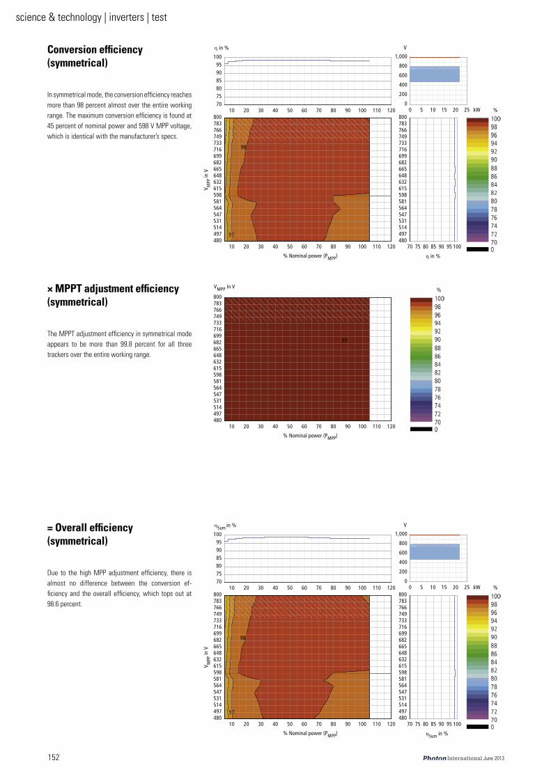
Conversion efficiency (symmetrical)
In symmetrical mode, the conversion efficiency reaches more than 98 percent almost over the entire working range. The maximum conversion efficiency is found at 45 percent of nominal power and 598 V MPP voltage, which is identical with the manufacturer’s specs.
TM TR UM UR VM VR NMMQUMQVTRNQRPNRQTRSQRUNRVUSNRSPOSQUSSRSUOSVVTNSTPPTQVTSSTUPUMM
M R NM NR OM ORM
OMM
QMM
SMM
UMM
NIMMM
NM OM PM QM RM SM TM UM VM NMM NNM NOMTMTRUMURVMVR
NMM
VT
NM OM PM QM RM SM TM UM VM NMM NNM NOMQUMQVTRNQRPNRQTRSQRUNRVUSNRSPOSQUSSRSUOSVVTNSTPPTQVTSSTUPUMM
η áå=B s
ât B
η áå=BB=kçãáå~ä=éçïÉê=EmjmmF
s jmm=áå=s
VU
NM OM PM QM RM SM TM UM VM NMM NNM NOMQUMQVTRNQRPNRQTRSQRUNRVUSNRSPOSQUSSRSUOSVVTNSTPPTQVTSSTUPUMM
B
B=kçãáå~ä=éçïÉê=EmjmmF
sjmm=áå=s
VV
TM TR UM UR VM VR NMMQUMQVTRNQRPNRQTRSQRUNRVUSNRSPOSQUSSRSUOSVVTNSTPPTQVTSSTUPUMM
M R NM NR OM ORM
OMM
QMM
SMM
UMM
NIMMM
NM OM PM QM RM SM TM UM VM NMM NNM NOMTMTRUMURVMVR
NMM
VT
NM OM PM QM RM SM TM UM VM NMM NNM NOMQUMQVTRNQRPNRQTRSQRUNRVUSNRSPOSQUSSRSUOSVVTNSTPPTQVTSSTUPUMM
ηpìã=áå=B s
ât B
ηpìã=áå=BB=kçãáå~ä=éçïÉê=EmjmmF
s jmm=áå=s
VU
× MPPT adjustment efficiency (symmetrical)
The MPPT adjustment efficiency in symmetrical mode appears to be more than 99.8 percent for all three trackers over the entire working range.
= Overall efficiency (symmetrical)
Due to the high MPP adjustment efficiency, there is almost no difference between the conversion ef-ficiency and the overall efficiency, which tops out at 98.6 percent.
science & technology | inverters | test
June 2013 153
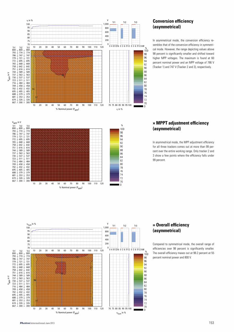
Conversion efficiency (asymmetrical)
In asymmetrical mode, the conversion efficiency re-sembles that of the conversion efficiency in symmetri-cal mode. However, the range depicting values above 98 percent is significantly smaller and shifted toward higher MPP voltages. The maximum is found at 60 percent nominal power and an MPP voltage of 786 V (Tracker 1) and 747 V (Tracker 2 and 3), respectively.
TM TR UM UR VM VR NMM
M Q UNONSM
OMM
QMM
SMM
UMM
NIMMM
NM OM PM QM RM SM TM UM VM NMM NNM NOMTMTRUMURVMVR
NMM
M P S VNO
PMMPOSPRPPTVQMRQPOQRUQUQRNNRPTRSPRUVSNSSQOSSUSVRTONTQTTTQUMM
PMMPOSPRPPTVQMRQPOQRUQUQRNNRPTRSPRUVSNSSQOSSUSVRTONTQTTTQUMM
M P S VNO
VS
VT
VU
NM OM PM QM RM SM TM UM VM NMM NNM NOMSSTSTQSUNSUUSVRTMOTMVTNSTOPTPMTPTTQQTRNTRUTSRTTOTTVTUSTVPUMM
qêP
qêPqêOqêN
qêOqêNη áå=B s
âtB
η áå=BB=kçãáå~ä=éçïÉê=EmjmmF
s jmm=áå=s
PMMPOSPRPPTVQMRQPOQRUQUQRNNRPTRSPRUVSNSSQOSSUSVRTONTQTTTQUMM
PMMPOSPRPPTVQMRQPOQRUQUQRNNRPTRSPRUVSNSSQOSSUSVRTONTQTTTQUMM
NM OM PM QM RM SM TM UM VM NMM NNM NOMSSTSTQSUNSUUSVRTMOTMVTNSTOPTPMTPTTQQTRNTRUTSRTTOTTVTUSTVPUMMqêN qêPqêO B
B=kçãáå~ä=éçïÉê=EmjmmF
sjmm=áå=s
TM TR UM UR VM VR NMM
M Q UNONSM
OMM
QMM
SMM
UMM
NIMMM
NM OM PM QM RM SM TM UM VM NMM NNM NOMTMTRUMURVMVR
NMM
M P S VNO
PMMPOSPRPPTVQMRQPOQRUQUQRNNRPTRSPRUVSNSSQOSSUSVRTONTQTTTQUMM
PMMPOSPRPPTVQMRQPOQRUQUQRNNRPTRSPRUVSNSSQOSSUSVRTONTQTTTQUMM
M P S VNO
VT
VU
VU
VT
NM OM PM QM RM SM TM UM VM NMM NNM NOMSSTSTQSUNSUUSVRTMOTMVTNSTOPTPMTPTTQQTRNTRUTSRTTOTTVTUSTVPUMM
qêP
qêPqêOqêN
qêOqêNηpìã=
áå=B s
âtB
ηpìã=áå=BB=kçãáå~ä=éçïÉê=EmjmmF
s jmm=áå=s
VS
× MPPT adjustment efficiency (asymmetrical)
In asymmetrical mode, the MPP adjustment efficiency for all three trackers comes out at more than 99 per-cent over the entire working range. Only tracker 2 and 3 show a few points where the efficiency falls under 99 percent.
= Overall efficiency (asymmetrical)
Compared to symmetrical mode, the overall range of efficiencies over 98 percent is significantly smaller. The overall efficiency maxes out at 98.2 percent at 55 percent nominal power and 800 V.

154 June 2013
science & technology | inverters | test
Conversion efficiency (parallel)
If the trackers are in parallel mode, the inverter basi-cally functions as a one-tracker device. In this case, the conversion efficiencies are almost identical to those in symmetrical mode. The maximum conversion efficiency of 98.6 percent is found at 50 percent nomi-nal power and 598 V MPP voltage.
TM TR UM UR VM VR NMMQUMQVTRNQRPNRQTRSQRUNRVUSNRSPOSQUSSRSUOSVVTNSTPPTQVTSSTUPUMM
M R NM NR OM ORM
OMM
QMM
SMM
UMM
NIMMM
NM OM PM QM RM SM TM UM VM NMM NNM NOMTMTRUMURVMVR
NMM
VT
NM OM PM QM RM SM TM UM VM NMM NNM NOMQUMQVTRNQRPNRQTRSQRUNRVUSNRSPOSQUSSRSUOSVVTNSTPPTQVTSSTUPUMM
η áå=B s
ât B
η áå=BB=kçãáå~ä=éçïÉê=EmjmmF
s jmm=áå=s
VU
VV
VV
VV
NM OM PM QM RM SM TM UM VM NMM NNM NOMQUMQVTRNQRPNRQTRSQRUNRVUSNRSPOSQUSSRSUOSVVTNSTPPTQVTSSTUPUMM
B
B=kçãáå~ä=éçïÉê=EmjmmF
sjmm=áå=s
TM TR UM UR VM VR NMMQUMQVTRNQRPNRQTRSQRUNRVUSNRSPOSQUSSRSUOSVVTNSTPPTQVTSSTUPUMM
M R NM NR OM ORM
OMM
QMM
SMM
UMM
NIMMM
NM OM PM QM RM SM TM UM VM NMM NNM NOMTMTRUMURVMVR
NMM
VT
VU VU
NM OM PM QM RM SM TM UM VM NMM NNM NOMQUMQVTRNQRPNRQTRSQRUNRVUSNRSPOSQUSSRSUOSVVTNSTPPTQVTSSTUPUMM
ηpìã=áå=B s
ât B
ηpìã=áå=BB=kçãáå~ä=éçïÉê=EmjmmF
s jmm=áå=s
× MPPT adjustment efficiency (parallel)
The MPP adjustment efficiency is almost always over 99 percent, with the only exception at 5 percent load.
= Overall efficiency (parallel)
In parallel mode, the vertical line at 45 percent nomi-nal power and the horizontal line at 598 V MPP voltage mark the maximum of 98.6 percent – which is identical to that achieved under symmetrical mode.

science & technology | inverters | test
June 2013 155
thin-film capacitors, the energy flows into an »3 level T-type« output bridge, which Huawei developed and patented. »3 level T-type« de-scribes a three point half bridge with one arm from the midpoint of the transistor half bridge to the midpoint of the capacitor half bridge of the intermediate voltage circuit. The voltage cir-cuit features two anti-parallel transistor diodes that are connected in series. The transistors and the diodes of the power stage are designed as six integrated modules. The following chokes smooth the voltages blocks into sinusoidal waves with a grid frequency of 50 Hz.
A subsequent automatic disconnect sepa-rates the inverter from the grid if it detects that grid voltage or frequency deviate from prede-termined values. Additionally, the unit moni-tors for grid-side leakage current and excessive insulation resistance on the DC side. An output filter, installed directly in front of the grid ter-minal, filters out radio interference.
Measurements
All of the following measurements are based on a grid voltage of 230 V. The Sun2000-20KTL’s maximum DC voltage is 1,000 V, and its DC nominal power is 20,600 W, a solar system of no more than 22,500 W can be connected to this inverter.
Due to the inverter’s multitracker design, the MPP voltage range can be defined in sev-eral ways:
Case 1: If the DC power is distributed symmetrically to the MPP trackers and is given as the sum of DC nominal power, then the MPP voltage range can be defined in the same way as for single-tracker inverters. That is, the inverter can process 100 percent of its DC nominal power at any voltage level within this range.
Case 2: If the DC power distribution can be divided asymmetrically among the number of tracker inputs, the product’s datasheet must specify the DC system nominal power and the maximum power of each individual tracker. Consequently, there are two complementary definitions for the MPP voltage range: a range for the tracker or trackers operating at maxi-mum DC power and for the other tracker or trackers operating at reduced power.
Case 3: Another option is to connect the trackers in parallel.
To allow for easy comparison, the PHOTON efficiency is calculated based only on the device’s performance while the MPP trackers are operat-ing under a symmetrical load (scenario one).
Locating the MPP: At the start of testing, the DC and AC sides were shut off. At a pre-determined IV curve with nominal power and an MPP voltage of 632 V, the inverter needs 1 minute to connect to the grid and another 57 seconds until all three trackers reach their MPP. When switching from 632 V to 615 V, the in-verter takes 22 seconds. While switching to 648 V, it takes 26 seconds.
MPP range: The Sun2000-20KTL’s MPP range stretches from 480 to 800 V, which makes it a wide-range inverter. For silicon crystalline modules, the maximum MPP voltage is suf-ficiently separated from the maximum input voltage of 1,000 V. For thin-film modules, the distance is a little too narrow. Given the three ways the MPP trackers can work under load, there are different MPP ranges as well.1) All three trackers face a load of one third of
the DC nominal power, respectively. In this case the MPP range spans from 480 to 800 V and equals that of a wide-range inverter.
2) Tracker 1 faces a load of 12,000 W in the range of 677 to 800 V, while tracker 2 works in the range of 300 to 800 V with a load of up to 3,200 W. Tracker 3 works within the same voltage range as tracker 2 and faces the re-maining load of 5,400 W.
3) All three trackers work in parallel mode within a voltage range of 480 to 800 V fac-ing the DC nominal power of 20,600 W. The Sun2000-20KTL is able to adjust to this mode automatically.
Conversion efficiency: The inverter can pro-cess 105 percent of its nominal power in an MPP voltage range of 480 to 800 V. Hence, ef-ficiencies could be calculated for this range.
At the top of the diagram, the hatching in the small area around 1,000 V represents limita-tions when the inverter is used with thin-film modules. These limitations are due to the insuf-ficient distance between the maximum MPP and maximum DC voltages. 1) In symmetrical mode, the range for the
maximum conversion efficiency starts at 25 percent of the nominal power and stretches over the whole MPP range from 480 to 800 V. If the current is above 80 percent of the nominal power, the inverter can’t keep its ef-ficiency above 98 percent if the voltage falls below 615 V. The maximum conversion effi-ciency of 98.6 percent is reached at 45 percent of nominal power and a MPP voltage of 598 V, which equals the value the manufacturer claims. The conversion efficiency loses about 0.5 percentage points toward smaller MPP voltages and up to 0.4 percentage points to-ward high voltages. At power levels below 15 percent of the nominal power, the conversion efficiency is reduced by up to 4.3 percentage points. At nominal power, the power factor cos φ was about one.
2) In asymmetrical mode, the large plateau that marks the area of maximum conversion effi-ciency is pretty close to the one in symmetri-cal mode except that it is significantly smaller and has moved toward higher MPP voltages. The asymmetric is very pronounced, and it is remarkable that the inverter dials all the trackers in at the same voltage when the highest MPP voltage is used. The reason for this is that the device chooses its operation mode by itself and if the open circuit voltages are very close to each other it changes the tracker to parallel mode. As a result, the dif-
ference between the defined MPP voltages is much smaller in the upper voltage range than in the lower voltage range. We find the maxi-mum conversion efficiency of 98.3 percent at 60 percent nominal power and MPP voltages of 786 V (tracker 1) and 747 V (tracker 2 and 3). The hatching reflects the limit of tracker 1.
3) In parallel mode, the efficiency curve turns out to be almost identical to the one in sym-metrical mode. The maximum conversion efficiency of 98.6 percent is reached at 50 percent nominal power and 598 V.
Weighed conversion efficiency: The Sun2000-20KTL’s European efficiency reaches its peak of 98.3 percent at a MPP voltage range of 598 to 648 V, which is identical to the manu-facturer’s statement. The difference between the inverter’s maximum conversion efficiency and its maximum European efficiency is 0.3 percentage points. The device’s maximum Californian efficiency is 0.2 percentage points higher at 98.5 percent, occurring in the MPP range of 598 V.MPPT adjustment efficiency: 1) In symmetrical mode, the Sun2000-
20KTL’s MPPT adjustment efficiency for all three trackers remains consistently above 99.8 percent.
2) In asymmetrical mode, the picture is pretty much the same. Over the whole range, the MPP adjustment efficiency for all three trackers is above 99 percent. There are only a few single points where tracker 2 and tracker 3 show values lower than 99 percent.
3) In parallel mode, the MPPT adjustment efficiency is again higher than 99 percent with a few exceptions at 5 percent of the nominal power.
Overall efficiency: The overall efficiency is cal-culated by multiplying the conversion efficiency and the MPPT adjustment efficiency.1) In symmetrical mode, the overall efficiency
shows no noticeable differences to the con-version efficiency, which was to be expected because of the high MPPT adjustment ef-ficiency. The overall efficiency maximum is 98.6 percent.
2) In asymmetrical mode the overall efficiency is 0.4 percentage points lower (98.2 percent) at 800 V and 55 percent of nominal power.
3) In parallel mode, the inverter functions like a one tracker device. The vertical line at 45 per-cent nominal power and the horizontal line at 598 V MPP voltage mark the maximum overall efficiency at 98.6 percent, which is identical to the results in symmetrical mode.
Course of overall efficiencies, average over-all efficiency and PHOTON efficiency: The overall efficiency curves for the symmetrical mode at different MPP voltages all start at high levels and fall ever so slightly after peaking. The PHOTON efficiency at medium irradiation is 98.0 percent, while the PHOTON efficiency at high irradiation is 98.1 percent, which trans-lates into an »A+« in both cases.

156 June 2013
science & technology | inverters | test
Weighted conversion efficiency
The European efficiency tops out in the range of 598 to 648 V MPP voltages and meets the manufacturer’s spec of 98.3 percent. The maximum California effi-ciency is 98.5.
QUM QVT RNQ RPN RQT RSQ RUN RVU SNR SPO SQU SSR SUO SVV TNS TPP TQV TSS TUP UMMTM
TO
TQ
TS
TU
UM
UO
UQ
US
UU
VM
VO
VQ
VS
VU
NMM
=bìêçéÉ~å=ïÉáÖÜíÉÇ==== ηbìêçj~ñ=Z=VUKP=B
=`~äáÑçêåá~å=ïÉáÖÜíÉÇ=== η`b`j~ñ==Z=VUKR=B
sjmm=áå=s
tÉáÖÜíÉÇ=ÅçåîÉêëáçå=ÉÑÑáÅáÉåÅó=ηbìêçI=η`b`=áå=B
ηbìêç=ã~åìÑ~ÅíìêÉê=ëéÉÅáÑáÉÇ=Z=VUKP=B
R NM NR OM OR PM PR QM QR RM RR SM SR TM TR UM UR VM VR NMM NMR NNM NNR NOMTM
TO
TQ
TS
TU
UM
UO
UQ
US
UU
VM
VO
VQ
VS
VU
NMMlîÉê~ää=ÉÑÑáÅáÉåÅó=ηpìã=áå=B
B=kçãáå~ä=éçïÉê=EmjmmF
==sjmm=Z=QUMKM=s=EsjmmãáåF ηpìãj~ñ=Z=VUKMS=B
==sjmm=Z=RVTKV=s=Esjmmηpìãj~ñj~ñF ηpìãj~ñ=Z=VUKRU=B
==sjmm=Z=UMMKM=s=Esjmmã~ñF ηpìãj~ñ=Z=VUKOQ=B
==^îÉê~ÖÉ=çîÉê~ää=ÉÑÑáÅáÉåÅó= η^îÖpìãj~ñ=Z=VUKOU=B
ηmãÉÇ=Z=VUKM=BI=ηmÜáÖÜ=Z=VUKN=B
ηpìãj~ñ
R NM NR OM OR PM PR QM QR RM RR SM SR TM TR UM UR VM VR NMM NMR NNM NNR NOMJPMJOUJOSJOQJOOJOMJNUJNSJNQJNOJNMJUJSJQJOMOQSU
NMNONQNSNUOMOOOQOSOUPM
=
B=kçãáå~ä=éçïÉê=EmjmmF
aÉîá~íáçå=áå=B
Overall efficiencies at different voltages
The overall efficiencies at different MPP voltages (in symmetrical mode) are very close together.
Accuracy of inverter display
The accuracy of the inverter display leaves very little room for improvement.

science & technology | inverters | test
June 2013 157
Manufacturer’s response
The efficiency measured in this test cor-responds to our own results, if one takes into consideration the degree of accuracy possible in such measurements. The result proves that inverters relying on standard silicon components, which were developed for multiple uses, still can achieve an »A+« rating for both medium and high irradiation.
Feed-in at nominal power: The inverter feeds in 100 percent of its nominal power over an input voltage range of 480 to 800 V at an am-bient temperature of 25 °C.
Displayed output power: The Sun2000-20KTL was fed output power varying from 5 to 100 percent of its nominal power at a constant MPP voltage of 632 V (that is, in the medium range). The output values displayed by the in-verter were compared with those recorded by a power analyzer. This revealed deviations of up to + 0.39 percent. Beyond 20 percent of nomi-nal power, the error level was about +/- 0.1 per-cent. This rises slightly once the inverter works in the overload range. This means that the ac-curacy of the display corresponds to a class B meter (similar to precision class 1).
Operation at high temperatures: As am-bient temperature increases, the Sun2000-20KTL feeds 100 percent of its nominal power into the grid up to around 59.2 °C (at 632 V MPP voltage). After that it reduces its power. The efficiency fell in this case by 0.18 percent-age points.
Overload behavior: If the Sun2000-20KTL is fed an overload of 1.3 times its nominal input power – 23,780 W – at an ambient temperature of 25 °C, the inverter limits DC output to 22,406 W. This corresponds to a load of 108.8 percent, which means the device has a small overload range. When power limitations take effect, the inverter pushes the operating point on the IV curve in the direction of higher input voltage. The DC voltage then adjusts to 698 V.
Own consumption and night consump-tion: In the version tested, the Sun2000-20KTL’s own consumption was around 0.8 W on the AC side and 21.9 W on the DC side. The manufac-turer doesn’t specify these values. At night, the inverter consumes around 0.9 W of real power from the grid. The manufacturer specifies less than 1 W here.
Thermography: Thermographic imaging shows the inverter from above while operating at nominal power and an ambient temperature of 25 °C. Due to the device’s many-layered de-sign, it was impossible to capture all compo-nents with thermographic imaging. Some of the components on the visible circuit boards showed component temperatures of up to 80.1 °C in the area of the output relays. The output chokes warmed up to 73.6 °C. It is obvious that the visible DC area is cooler than the visible AC area. The thin-film capacitors in the area of the filter were in green respective to the blue range of the temperature scale.
Summary
Overall the Sun2000-20KTL presented itself as an outstanding inverter. Even though it is designed with two levels of circuit boards, it re-mains well sorted. Since it does not need active cooling, the inverter can be mounted indoors as well as outdoors. Only if the temperature rises above about 60 °C does the inverter start to re-
duce its output, which does not pose a problem in real life. The overload capacity, 8.8 percent, turns out to be on the smaller side.
There are no limitations when designing PV systems with crystalline silicon modules: the maximum MPP voltage of 800 V keeps a healthy distance from the maximum DC input voltage of 1,000 V. Only for thin-film modules does the difference turn out to be a little too small. But according to the manufacturer, thin-film mod-ules can only be used if the module outs do not have any connection to the ground or if there is to be an electrical isolation installed on the inverter output side.
The inverter display only shows a small mar-gin of error and can be used to track the yield without hesitation. When it comes to the effi-ciencies, it turns out that they are almost iden-tical in all three different modes (symmetrical, asymmetrical and parallel) with the asymmet-rical mode being the least efficient. The maxi-mum conversion efficiency, 98.6 percent, offers exactly what the manufacturer promised. The MPPT adjustment efficiency in all three modes is equally as high over the whole working range and never falls below 99.8 percent for any of the trackers. The European efficiency reaches its maximum in the range of 598 to 648 V MPP voltages and confirms the manufacturer’s specs with 98.3 percent yet again. The overall efficien-cy is 98.6 percent.
To determine the PHOTON efficiency, only the symmetrical mode is used. For medium irradiation the PHOTON efficiency is 98.0 per-cent, for high irradiation it is 98.1 percent. That makes the Sun2000-20KTL the fourth inverter ever tested to achieve an »A+« for medium irra-diation. In the overall test ranking, the inverter comes in third, surpassed only by two inverters that both use silicon carbide transistors. Hua-wei does not build these transistors into their devices yet. In the end this is the first inverter from China that has the chance to give SMA a run for its money.
Text Heinz Neuenstein, Anne Kreutzmann

40 March 2013
business | inverters | huawei
High-tech at Chinese pricesHow leading ICT solutions supplier Huawei hopes to conquer the global PV inverter market
Despite its quickly growing international business, leading Chinese information and communication technology supplier Hua-wei is still a rather unknown brand beyond ICT circles. Now, Huawei – which recently recently caught up with the sales volume of global market leader Ericsson – wants to play in the premier division of solar invert-ers as well. Huawei targets to become, at a minimum, the world’s number three in the PV grid-connection segment. PHOTON Inter-national spoke with Roland Hümpfner, head of Huawei’s Research Center in Nuremberg, Germany. Hümpfner, who has been with Huawei since 2011, is also vice president of its uninterruptible power supply.
Huawei is planning on getting into the solar power business. Why solar?
There is a lot of overlap between PV and Huawei’s strong suit of telecommunications. For example, cell phone towers must be supplied with power, including those in relatively remote locations. Huawei has a history of providing turn-key solu-tions for powering, inter alia, diesel generators and batteries – including PV and wind power plants.
And why now?
Over the past 5 years, Huawei has become ac-customed to annual earnings growth just over 30 percent. Growth is one of Huawei’s goals, so we asked ourselves: How can we continue to
grow? This is what is driving Huawei to develop its portfolio in other related energy sectors full steam ahead. Photovoltaic inverters and unin-terruptible power supply are the two new prod-uct areas we now want to bring to market. This decision was actually made 3 years ago.
And why specifically inverters?
Inverters are a good match for Huawei since cutting-edge power electronics are used in the telecom business in the form of 48 V rectifiers. Our power electronics business also provides us with a solid foundation on which to build. Huawei is committed to becoming a technology leader, which is why we have invested in the Eu-ropean Research Center Energy in Nuremberg, Germany. The Nuremberg area offers good in-frastructure and a large number of suppliers, semiconductor manufacturers for the power electronics spectrum, and other resources.
So can we infer that this inverter technol-ogy was developed in Nuremberg?
With regard to development, we in Nuremberg work in close collaboration with our colleagues in China. We took the lead in the conceptual development of the SUN2000 series. We then worked jointly with our Chinese engineers to perfect its design and ready it for production.
This, of course, is not the first Chinese in-verter we have tested at PHOTON Lab. And

March 2013 41
many of them have had very high efficien-cies. Huawei, too, wants to compete in the highest efficiency class.
People expect a lot from Huawei. Our products have come to enjoy »world class« status. With such a reputation to uphold, we cannot afford to enter the market with a mediocre, made-in-China inverter. That just doesn’t cut it. Huawei places a lot of emphasis on innovation: a very large proportion of our 140,000-strong global workforce – a whopping 44 percent – is em-ployed in research and development. Huawei, moreover, invests 12 percent of its sales earn-ings in R&D. The goal is to enter the market at the top by offering customers real value: tech-nologically top-drawer inverters that are also attractively priced.
You say your devices will be »attractively priced«. So what do you expect them to cost per watt, say for a 20 kW inverter?
Huawei will adjust its pricing to align with mar-ket averages. The cost of an inverter usually rep-resents 10 to 15 percent of the cost of an entire system, depending on how big the installation is. This cost share will not change much in the future, either. When the end customer can pur-chase an entire system for €1,000 ($1,360) per kW, the cost of the inverter will also be priced accordingly, in proportion to the whole system. Based on this, 10 euro cents (14¢) per W is in the ballpark.
Roland Hümpfner is the head of Huawei’s European Research Center Energy in Nuremberg, Germany. He is also VP of its UPS and Inverter Product Line.
Hua
wei
Tec
hnol
ogie
s D
üsse
ldor
f Gm
bH

42 March 2013
I assume that is the price for installers, right?
It is difficult for us to predict what the prices for installers will be since we will be sell-ing our products through distributors. But I think we should keep our sights on the mid to long-term goal of 10 euro cents (14¢) per W for installers.
The Huawei inverter that we have in our lab still uses the classic IGBT (insulated-gate bipolar transistor) rather than silicon car-bide transistors. Is there a special reason for this?
We researched this matter thoroughly. We do not feel that silicon carbide switches are ready yet for series production on a large scale. Moreover, without using silicon car-bide, we are playing in the same league in terms of efficiency as devices that do use it. So we currently see no need to use that technology.
Are you also concerned about there being too few supply sources?
Exactly. If all inverter manufacturers were to convert to silicon carbide today, the sili-con carbide industry would not be able to cope with the demand. Also, silicon carbide transistors are more expensive because it is technologically quite difficult to produce good ones. If and when silicon carbide tran-sistors become cheap and readily available from many suppliers, we will again consider using them.
What we have observed is that silicon carbide switches are definitely already being used here and there, but so far mostly as a relatively simple substitute for the IGBT. Manufacturers use their existing IGBT topology with the same switching frequencies but then use the silicon carbide transistors to achieve half a percentage point more efficiency. But they don’t exploit the ability afforded by silicon carbide transistors to raise pulse frequency in order to save on component costs.
This technology will certainly continue to de-velop, and then we will have to see what the market demands – more efficiency or more price concessions.
Regardless, you will no doubt be able to pro-duce your inverters very inexpensively since you can buy the components at lower costs.
Of course, with our many suppliers, Huawei can negotiate high volume discounts. But this is also why we decided to stick with standard components – to ensure we can continue to de-liver our products to customers.
So how much market share are you aim-ing for?
We want to become one of the top-tier suppli-ers. Long term, we want to be in the top three. It remains to be seen how long it will take us to achieve this and whether we can do so quickly with our first generation products.
Have you set specific sales volume goals for this or next year?
Yes, but we can’t discuss that here.
So what is your inverter production capac-ity, then?
We want to expand into the multi-hundred megawatt range. Production will take place at facilities in the Song Shan Lake Science and Technology Industrial Park in Dongguan, about 30 km north of Shenzhen.
What, then, is your expectation as to how inverter prices will develop?
Some manufacturers are already feeling some price pressure today, which means their profit margins will be subject to a little more pressure. There is a lot of competition in the PV sector and this will give rise to a technology race as well. In the final analysis, we can simply state that in-verter production costs are very closely related to weight and volume. With higher power densi-ties, prices in the future could go down more.
How will you make your inverters appeal to installers, especially when it comes to things like service and support?
We will have the standard service strategy and policies which are demanded by the market and fulfilled by the installer, distributor and manufacturer working in close coordination with each other. Huawei has a worldwide ser-vice network. We have very good coverage in Germany, for example. In addition, we are making an effort to simplify the knowledge needed by the user in such a way that it can be communicated very quickly. And when there is a problem, we will provide a substi-tute device with no hassles. We will not be able to succeed unless we strive to make things as easy as possible for the end user and installer. We are aware of this.
Do you use your own service personnel?
Service is provided partly by our own employ-ees and partly outsourced. In Germany, for example, Huawei has its own service company. They have really great infrastructure there and relatively short response times, so they can pro-vide assistance locally very quickly – in fact, quicker than is typical for solar technology to-day. In the telecommunications field, you have
to be able to provide assistance within hours. So you have about 2 to 4 hours to get from your central office out to wherever.
Inverter manufacturers are increasingly of-fering devices that include a built-in battery or that can be retrofitted with one.
That is an interesting idea. I like it very much. We have a lot of experience with our battery systems in setting up cell towers in areas with-out or with only poor access to the grid. We have set up about 180,000 battery-based power supply systems, some of which are already equipped with solar generators. These systems are extremely accessible and, in the future, we will be offering them outside of the telecom field as well.
Let’s talk about grid stability: How important is this topic to Huawei and how will your inverters be able to make a positive contri-bution in this area?
Huawei is on board with the smart grid idea. We are examining the question of additional uses for inverters. Inverters are capable, with-out much extra investment, of maintaining grid stability. There are quite a few possibilities in this area. For example, you can limit peak out-put under certain circumstances. If you hold back a certain reserve capacity – for example, not feed all available energy into the grid but rather, say, 10 percent less than the maximum – then in effect you have created a virtual 10 percent reserve. This can be used to stabilize the grid and very profitably at that.
Let’s say I am an installer in Germany who has been using SMA inverters for 20 years. How will you persuade me to try out a Hua-wei inverter?
We have spoken with a number of installers. They are very open about trying something new. Many of them really like to experiment. And with the Huawei name, we find ourselves very well received. When we say, »We are from Huawei,« people want to talk to us. They say, »Yeah, okay. Sounds good.« There is a gen-eral climate in which Chinese manufacturers, too, are now being considered by many, many installers. On the other hand, people expect Huawei to deliver world-class products with cutting-edge technology at Chinese prices. I am convinced that we will be able to meet these ex-pectations.
Thank you for the interview.
Interview Anne Kreutzmann
business | inverters | huawei

58 June 2013
Inverter test resultsInverter Observed
voltage range*1
Medium irradiation High irradiation PI issue
etaPmed Grade as of 2011
Grade before 2011
Position etaPhigh Grade as of 2011
Grade before 2011
Position
SMA’s STP 20000TLHE-10*3 580 - 800 V 98.5 % A+ – 1 98.6 % A+ – 1 12/2011Refusol’s 020k SCI 490 - 800 V 98.2 % A+ – 2 98.3 % A+ – 2 7/2012Huawei Technologies Co. Ltd.´s Sun2000-20KTL 480 - 800 V 98.0 % A+ – 3 98.1 % A+ – 3 6/2013Diehl AKO’s Platinum 16000 R3 350 - 720 V 98.0 % A+ – 3 98.0 % A+ – 4 3/2013Donauer Solartechnik’s High Efficiency 3.6 350 - 650 V 97.8 % A – 5 97.9 % A – 5 12/2012Steca’s StecaGrid 3600 350 - 600 V 97.7 % A – 6 97.8 % A – 6 12/2011Steca’s Stecagrid 3000 350 - 700 V 97.5 % A – 7 97.8 % A – 6 9/2012Siemens’ Sinvert PVM20 480 - 850 V 97.5 % A – 7 97.7 % A – 8 4/2011Sungrow’s SG30KTL 480 - 800 V 97.5 % A – 7 97.7 % A – 8 2/2013Siemens’ Sinvert PVM17 460 - 850 V 97.4 % A – 10 97.7 % A – 8 4/2011Refusol’s 017K 460 - 850 V 97.4 % A A+ 10 97.6 % A A+ 11 12/2010Global Mainstream Dynamic´s Soldate 318KTLE 490 - 800 V 97.3 % A – 12 97.6 % A – 11 –*9
Refusol’s 013K 420 - 850 V 97.3 % A A+ 12 97.6 % A A+ 11 12/2010Siemens’ Sinvert PVM13 420 - 850 V 97.3 % A – 12 97.6 % A – 11 4/2011Refusol’s 020K 480 - 850 V 97.3 % A – 12 97.5 % A – 15 3/2012SMA’s STP 17000TL 400 - 800 V 97.3 % A A+ 12 97.5 % A A+ 15 12/2010SMA’s STP 10000TL-10 320 - 800 V 97.1 % A – 17 97.5 % A – 15 10/2011Chint Power’s CPS SC20KTL-O 500 - 800 V 97.1 % A – 17 97.4 % A – 18 11/2011Siemens’ Sinvert PVM10 380 - 850 V 97.0 % A – 19 97.4 % A – 18 1/2011Delta Energy Systems’ Solivia 20 EU G3 TL 350 - 800 V 97.0 % A – 19 97.2 % A – 22 3/2012Zeversolar New Energy’s Eversol-TLC 17k*2 550 - 720 V 96.9 % A – 21 97.3 % A – 20 4/2011Mastervolt’s Sunmaster CS20TL 350 - 800 V 96.9 % A – 21 97.2 % A – 22 5/2011Power-One’s Trio-27.6-TL-OUTD-S2-400 500 - 800 V 96.9 % A – 21 97.2 % A – 22 2/2013Refusol’s 011K*3 380 - 800 V 96.9 % A A+ 21 97.2 % A A+ 22 9/2008Goodwe Power Supply Technology’s GW4000-SS 280 - 500 V 96.9 % A – 21 97.1 % A – 26 12/2012SMA’s SMC 8000 TL*3 335 - 487 V 96.9 % A A+ 21 97.0 % A A+ 30 10/2007SMA’s SMC 11000TL*3 333 - 500 V 96.9 % A A+ 21 96.8 % A A+ 43 7/2010B&B Power´s SF 4600TL 250 - 500 V 96.8 % A – 28 97.3 % A – 20 –*9
science & technology | inverters | test

June 2013 59
Growatt’s 5000MTL (version 2) 250 - 540 V 96.8 % A – 28 97.1 % A – 26 12/2012
Sputnik’s Solarmax 13MT*4 250 - 750 V 96.8 % A – 28 97.1 % A – 26 9/2011
Diehl AKO’s Platinum 6300 TL*3 350 - 710 V 96.8 % A A+ 28 96.9 % A A+ 40 2/2009
Power-One’s TRIO-20.0-TL-OUTD S2-400 410 - 800 V 96.7 % A – 32 97.1 % A – 26 9/2012
Danfoss’ TLX 15 k 430 - 800 V 96.7 % A A+ 32 97.0 % A A+ 30 6/2010
Samil Power’s Solarlake 15000TL 380 - 800 V 96.7 % A – 32 97.0 % A – 30 6/2012
Zeversolar New Energy’s Eversol-TL 4600 290 - 500 V 96.7 % A – 32 97.0 % A – 30 9/2011
Sunways’ NT 4200 340 - 750 V 96.7 % A A+ 32 96.8 % A A+ 43 3/2010
Sunways’ PT33k 460 - 800 V 96.7 % A – 32 96.8 % A – 43 6/2012
Conergy’s IPG 15T 450 - 800 V 96.6 % A A+ 38 97.0 % A A+ 30 8/2010
Kinglong’s KLNE Solartec D 15000 480 - 750 V 96.6 % A – 38 97.0 % A – 30 3/2013
Kinglong’s KLNE Sunteams 5000 280 - 440 V 96.6 % A – 38 97.0 % A – 30 5/2012
Sungrow’s SG15KTL 380 - 800 V 96.6 % A – 38 97.0 % A – 30 2/2012
SMA’s SMC 7000TL*3 333 - 500 V 96.6 % A A+ 38 96.8 % A A+ 43 5/2010
Sunways’ NT 11000 340 - 750 V 96.6 % A – 38 96.7 % A – 51 11/2012
Danfoss’ TLX 10 k 430 - 800 V 96.5 % A A+ 44 97.0 % A A+ 30 8/2010
Eaton Phoenixtec MMPL´s SV 20000s 450 - 850 V 96.5 % A – 44 96.8 % A – 43 5/2013
Samil Power’s Solarriver SR4K4TLA1 200 - 500 V 96.5 % A – 44 96.8 % A – 43 8/2011
Eltek Valere’s Theia 4.4HE-t*5 230 - 480 V 96.5 % A – 44 96.7 % A – 51 11/2011
Power-One’s Aurora PVI-12.5-OUTD-FS*3 360 - 750 V 96.4 % B A 48 96.9 % A A+ 40 4/2010
SLD Power Technology´s SLS5KH65 225 - 500 V 96.4 % B – 48 96.7 % A – 51 5/2013
B&B Power’s SF 3000TL 250 - 450 V 96.3 % B – 50 96.9 % A – 40 4/2013
Helios’ HSI20 350 - 800 V 96.2 % B – 51 97.0 % A – 30 3/2012
Growatt’s 5000 MTL 250 - 550 V 96.2 % B – 51 96.8 % A – 43 7/2012
Kaco’s Powador 4000 supreme DCS (9 kHz) 350 - 510 V 96.2 % B A 51 96.7 % A A+ 51 1/2010
Kstar’s New Energy KSG-5K (version 2) 280 - 480 V 96.2 % B – 51 96.6 % A – 55 12/2012
Kstar’s New Energy KSG-3 190 - 440 V 96.1 % B – 55 96.6 % A – 55 8/2012
Trannergy’s PVI 4600TL 300 - 500 V 96.1 % B – 55 96.6 % A – 55 8/2012
Growatt’s 5000 TL*3 280 - 500 V 96.0 % B – 57 96.8 % A – 43 2/2011
Fronius’ IG TL 5.0 350 - 700 V 95.9 % B A 58 96.2 % B A 59 9/2010
Kaco’s Powador 4000 supreme DCS (18 kHz) 350 - 510 V 95.7 % B A 59 96.1 % B A 60 1/2010
SMA’s SB 5000TL-20*3 175 - 440 V 95.7 % B A 59 96.0 % B A 62 5/2009
Sungrow’s SG4KTL 210 - 420 V 95.6 % B – 61 96.3 % B – 58 1/2011
Omron’s KP100L (OD-EU) 320 - 825 V 95.5 % B – 62 96.1 % B – 60 1/2013
Sanjing Electric’s SAJ Sununo TL5K 200 - 440 V 95.5 % B – 62 96.0 % B – 62 5/2012
Power-One’s Aurora PVI-6000-OUTD-S*3 180 - 530 V 95.4 % B A 64 95.9 % B A 64 3/2009
Omnik New Energy’s Omniksol-2k-TL 120 - 450 V 95.2 % B – 65 95.9 % B – 64 1/2012
Aros’ Sirio 4000*3, 8 250 - 450 V 95.1 % B A 66 95.7 % B A 67 12/2008
Dasstech’s DSP-123K2 200 - 450 V 95.1 % B – 66 95.7 % B – 67 3/2011
Kstar’s New Energy KSG-5K (version 1) 280 - 480 V 95.1 % B – 66 95.1 % B – 74 12/2012
Conergy’s IPG 5 S*3 275 - 750 V 95.0 % B A 69 95.8 % B A 66 9/2009
Fronius’ IG Plus 100*3 230 - 500 V 94.8 % C B 70 95.0 % B A 78 11/2010
SMA’s SB 3000HF-30 210 - 560 V 94.7 % C – 71 95.2 % B – 72 2/2012
Power-One’s Uno-2.5-I-OUTD-S 200 - 470 V 94.6 % C – 72 95.4 % B – 70 4/2013
Yisun New Energy Tech’s Yisun-2K-TL 120 - 450 V 94.6 % C – 72 95.4 % B – 70 12/2012
Fronius’ IG Plus 150 V-3 230 - 500 V 94.6 % C – 72 95.1 % B – 74 10/2012
Sunways’ AT 4500 250 - 600 V 94.6 % C B 72 94.8 % C B 83 7/2008
Sungrow’s SG3KTL (version 2) 180 - 420 V 94.5 % C – 76 95.7 % B – 67 8/2011
Fronius’ IG Plus 50 230 - 500 V 94.5 % C B 76 94.8 % C B 83 8/2008
Phoenixtec’s PVG 2800 (updated model) 250 - 450 V 94.4 % C B 78 95.1 % B A 74 5/2008
Kaco’s Powador 8000xi (new software; since Jan. 2010)*3
350 - 600 V 94.4 % C B 78 94.7 % C B 87 3/2010
Kaco’s Powador 2500xi DCS*3 350 - 600 V 94.3 % C B 80 95.0 % B A 78 1/2010
Motech Industries´s PVMate 5000E 200 - 550 V 94.3 % C – 80 94.9 % C – 82 6/2013
Sunways’ AT 2700 181 - 600 V 94.3 % C B 80 94.8 % C B 83 8/2009
Sputnik’s SolarMax 6000S 220 - 550 V 94.3 % C B 80 94.7 % C B 87 11/2009
Effekta’s ES5000 (new software, PV00113L) 150 - 450 V 94.2 % C – 84 94.8 % C – 83 2/2012
Carlo Gavazzi’s ISMG150DE 200 - 450 V 94.1 % C B 85 95.0 % B A 78 5/2010
Xantrex’s GT5.0SP*6,*3 240 - 550 V 94.1 % C B 85 94.7 % C B 87 1/2009
Conergy’s IPG 5000 vision*3 301 - 706 V 94.0 % C B 87 94.7 % C B 87 7/2007
Kaco’s Powador 8000xi (old firmware; till Jan. 2010)*3 350 - 600 V 94.0 % C B 87 94.7 % C B 87 3/2010
Kostal’s Piko 10.1 400 - 850 V 94.0 % C B 87 94.4 % C B 99 7/2009
Delta Energy Systems’ SI 3300*3 150 - 435 V 93.9 % C B 90 94.7 % C B 87 5/2008
Mitsubishi’s PV-PNS06ATL-GER 260 - 650 V 93.9 % C B 90 94.6 % C B 93 6/2008
SMA’s SMC 7000HV*3 335 - 560V 93.9 % C B 90 94.2 % C B 101 9/2009
Inverter test resultsInverter Observed
voltage range*1
Medium irradiation High irradiation PI issue
etaPmed Grade as of 2011
Grade before 2011
Position etaPhigh Grade as of 2011
Grade before 2011
Position

60 June 2013
New grades in PHOTON Lab’s inverter test as of 2011The table showing the results achieved by the inverters tested by PHOTON Lab looks slightly different due to a new grading sys-tem as of 2011. All of the inverters tested before that point have two grades: one based on the old system and one related to the new method.
The grades are based on the PHOTON efficiency at medium and high irradiation. More detailed information about the invert-
ers can be found in the corresponding test reports (the issue in which each report was published is noted in the last column of the table). The rankings are also based on the PHOTON efficiency.
The changes to the grading system were made to reflect the current status in the sector; and the system will be updated again in the fu-ture to reflect technical advancements. Now, in-verters have to get a higher PHOTON efficiency
to secure a better grade: what would have gotten an A in 2010 with 96.4 percent, would now get a B. Should manufacturers further im-prove their devices, these inverters could even get downgraded to a C as our grading system changes to reflect the current times.
Moreover, to align grades with our US sister publication, we have changed the letter »E« to »F,« based on the American school grading system.
Grading system for inverter tests as of 2011A++ A+ A B C D F*1
PHOTON efficiency ≥ 99 ≥ 98 - < 99 ≥ 96.5 - < 98 ≥ 95 - < 96.5 ≥ 93.5 - < 95 ≥ 92 - < 93.5 < 92
Deviation from next grade 0.5 1 1.5 1.5 1.5 1.5 –
*1 to align grades with our US sister publication, we have changed the letter »E« to »F«
science & technology | inverters | test
Sunways’ NT 2600 (lower range)*3 350 - 623 V 93.8 % C B 93 95.1 % B A 74 11/2007
Steca’s Stecagrid 9000 3ph*3 350 - 680 V 93.8 % C B 93 95.0 % B A 78 7/2010
Sputnik’s SolarMax 2000C*3 165 - 515 V 93.8 % C B 93 93.1 % D C 114 4/2007
Sungrow’s SG3KTL (version 1) 180 - 420 V 93.7 % C – 96 95.2 % B – 72 8/2011
Kaco’s Powador 4202 200 - 510 V 93.7 % C B 96 94.6 % C B 93 10/2010
SMA’s SB 2100TL 200 - 480 V 93.7 % C B 96 94.6 % C B 93 6/2009
Oelmaier’s PAC 4 330 - 600 V 93.6 % C B 99 94.6 % C B 93 12/2009
Mastervolt’s Sunmaster XS6500 180 - 480 V 93.6 % C B 99 94.1 % C B 102 2/2010
Ingeteam’s Ingecon Sun 3.3 TL 159 - 414 V 93.4 % D C 101 94.3 % C B 100 8/2007
SMA’s SB 3800*3 208 - 395 V 93.2 % D C 102 93.6 % C B 106 2/2007
Dasstech’s DSP-123KH*3 350 - 600 V 93.0 % D C 103 94.6 % C B 93 10/2010
Diehl AKO’s Platinum 4600S 320 - 628 V 92.9 % D C 104 93.3 % D C 111 4/2008
Power-One’s Aurora PVI-2000-OUTD-DE*3 210 - 530 V 92.8 % D C 105 94.0 % C B 103 2/2010
Diehl AKO’s Platinum 2100S 206 - 390 V 92.8 % D C 105 93.3 % D C 111 10/2009
Kaco’s Powador 3501xi*3 125 - 391 V 92.6 % D C 107 92.9 % D C 115 6/2007
Kaco’s Powador 2500xi*3 350 - 597 V 92.5 % D C 108 93.4 % D C 108 12/2007
Sunways’ NT 2600 (upper range)*3 476 - 749 V 92.3 % D C 109 93.9 % C B 104 11/2007
Solon’s Satis 40/750 IT*7 375 - 575 V 92.3 % D C 109 93.5 % C B 107 11/2008
Mastervolt’s QS 2000*3 212 - 366 V 92.3 % D C 109 92.7 % D C 116 1/2008
Opti-Solar’s GT 4000 (new software, V2.07) 250 - 400 V 92.1 % D – 112 94.6 % C – 93 6/2011
Powercom’s SLK-4000 205 - 408 V 92.0 % D C 113 93.4 % D C 108 11/2010
Phoenixtec’s PVG 10000 320 - 720 V 91.8 % F D 114 93.3 % D C 111 6/2010
Riello’s HP 4065REL-D*3,*8 255 - 435 V 91.7 % F D 115 93.9 % C B 104 9/2007
Effekta’s ES5000 (old software) 150 - 450 V 91.7 % F – 115 92.2 % D – 117 2/2012
Fronius’ IG 30 150 - 397 V 91.4 % F D 117 92.2 % D C 117 1/2007
Powercom’s SLK-4000 (new software, V2.07) 250 - 450 V 91.1 % F – 118 93.4 % D – 108 6/2011
Siemens’ Sitop solar 1100 Master*3 200 - 552 V 90.2 % F D 119 91.7 % F D 120 5/2007
Danfoss’ ULX 1800 HV IN*3 260 - 500 V 89.2 % F F 120 91.3 % F D 122 4/2010
SMA’s SB1100 139 - 320 V 89.1 % F F 121 90.5 % F D 124 10/2009
Opti-Solar’s GT 4000 (old software, V1.09) 200 - 450 V 87.8 % F – 122 92.1 % D – 119 6/2011
Ehe New Energy’s EHE-N2K5 200 - 400 V 87.4 % F – 123 91.4 % F – 121 7/2011
SunnySwiss’ SSP-6000 250 - 480 V 86.8 % F – 124 91.2 % F – 123 2/2011
Ehe New Energy’s EHE-N5K 300 - 650 V 80.3 % F – 125 86.3 % F – 125 7/2011
Phoenixtec’s PVG 2800 (original model)*3 255 - 435 V 78.4 % F F 126 85.8 % F F 126 2/2008
*1 range at which the model was tested and to which the grade applies, *2 Eversolar New Energy Co. Ltd. and Zof New Energy Co. Ltd. merged at the end of 2011 and altered their name to Zeversolar New Energy Co. Ltd.; Zeversolar now calls the device the Eversol TL 17k; however, the power data differs from the tested Eversol-T, *3 device no longer being produced, *4 renamed Solarmax 13MT3 since April 2012, *5 name changed from Eltek Valere to Eltek, *6 now Schneider Electric Industries SA, *7 prototype; device no longer being produced, *8 the identical solar inverter brands Helios Power (Riello UPS) and Sirio (AROS) are now marketed under a single brand, AROS Solar Technology GmbH, and distributed by AROS Neufahrn, *9 inverters that have been already tested by PHOTON Lab, but results are not yet published in the magazine
Inverter test resultsInverter Observed
voltage range*1
Medium irradiation High irradiation PI issue
etaPmed Grade as of 2011
Grade before 2011
Position etaPhigh Grade as of 2011
Grade before 2011
Position