school of science and engineering t… · school of science and engineering automating the urbanism...
TRANSCRIPT

SCHOOL OF SCIENCE & ENGINEERING – AL AKHAWAYN UNIVERSITY
SCHOOL OF SCIENCE AND ENGINEERING
AUTOMATING THE URBANISM SERVICE WITHIN A
TYPICAL MOROCCAN COMMUNE
EGR 4402: Capstone Design
18 April 2017
Imane Kaddouri
Supervised by Dr. Driss Kettani .

2
URBANISM SERVICE SYSTEM
Capstone Final Report
_____________________________________________________
Capstone Student: Imane Kaddouri
Approved by the Supervisor
_____________________________________________________
SUPERVISOR: Dr. Driss Kettani
3
ACKNOWLEDGEMENTS
I would like to express my sincere thanks and appreciation to Dr. Driss Kettani, my
supervisor, for giving me the opportunity and for helping me carrying out this capstone
project. I would also like to thank him for the knowledge I acquired from him through several
courses as well as my internship that he supervised, and which were of great help to me
throughout this capstone.
I would also like to express my thanks to the general director Mrs. Houda Chakiri and
to Mr. Zouheir Chakiri of Enhanced Technologies for giving me the opportunity to work on a
real life project as my capstone, and for their availability and their help.
4
CONTENTS
1 Introduction 7
2 Methodology 8
3 STEEPLE Analysis 9
4 The Software Engineering Process 10
5 Requirements Specification 12
5.1 Description of the Meetings 12
5.2 Draft N°1 14
5.3 Draft N°2 15
5.4 Stable Version 18
5.4.1 Functional Requirements 18
5.4.2 Non-Functional Requirements 24
6 Workflow Activity Diagram 26
7 Users Vs System Activity Diagrams 29
7.1 Citizen Vs System 29
7.2 Employee Vs System 30
7.3 Commission Vs System 31
7.4 Taxation Vs System 32
7.5 Architect Vs System 33
7.6 President Vs System 34
7.7 Technician Vs System 35
7.8 Admin Vs System 36
8 Data Modelling 37
8.1. Conceptual Data Model 37
8.1.1. Procedure 37
8.1.2. Results 38
8.2. Physical Data Model 44
8.2.1. Procedure 44
8.2.2. Enhanced Entity Relation Diagram 45
9 Design 57
9.1. System Architecture 57
9.1.1. Description 57
9.1.2. Advantages 58
9.2. Technology Enablers 58
9.3. Enhanced System Architecture 61
10 Implementation 62

5
11 Main Challenges and Lessons Learned 65
12 Conclusion 66
13 Appendix 67

6
ABSTRACT
The Urbanism Service System is a JEE based web application using a MySQL
database, that automates the different steps of the issuance of a construction permit, as well as
manages the different types of users’ interfaces, departments and the different urbanism
documents traceability. Its main purpose is to facilitate the processes within an urbanism
service in Morocco, while increasing their efficiency, effectiveness, visibility and
transparency. Moreover, it will increase the accessibility of citizens to a public service, which
is low in most of Morocco.
This report first includes an introduction to the general context of the project, which is
the urbanism service in Morocco. It clearly states the problem, which is that most of these
services are still paper based, and the chosen option to solve it, which is this web application.
Second, it contains the methodology followed in this project, and which is an association of
primary research through interviews, and secondary research through online documentation.
Third, it includes the STEEPLE analysis, which shows the societal, technical, environmental,
ethical, political, legal and economic impacts of this project. Fourth, it contains both the
functional and non-functional requirements, the modelling through activity diagrams using
UML and their descriptions, the data modelling step which includes the conceptual and
physical data models along with their descriptions, the design step which features the system
architecture and technology enables, the implementation step and finally the main challenges
and lessons learned.

7
1 INTRODUCTION
The urbanism service’s mission is to shape the territorial project of the city and to
participate in the organization of the regional territory, to ensure a better harmony. It takes
care of the organization of building, the activities that have an impact on the territory and the
development of public spaces, and the distribution of public utilities.
Moreover, it takes care of the preservation of the built heritage, the implementation
and monitoring of the various tools for managing the territory (neighborhood plans, communal
master plan, general allocation plan, etc.) and the purchase and / or sale of strategic land
contributing to the harmonious development of the city.
Furthermore, it takes care of checking requests for building permits and issuing them,
the procedures for public inquiry and the inspection of construction sites. In addition to that, it
provides with information about the various land-use planning procedures, the building
permits, colors, the architectural census etc.
In Morocco, most - if not all - of the urbanism service processes are still paper based.
Paper based work can be both tedious and time consuming for both the citizens and the
employees. It also is more vulnerable to mistakes, losses and delays. It lacks efficiency and
effectiveness, as well transparency and visibility. It is therefore urgent to solve this
problematic situation.
The solution proposed is to build a JEE based web application that would automate the
different processes in an urbanism service. In addition to that, it would manage the different
types of users and trace the advancement of a project, as well as its associated documents. It
would also give the possibility to the different users, depending on their type, to have real time
access to information and services concerning the projects with which they might be involved.

8
2 METHODOLOGY
This project requires a deep understanding of what the urbanism service is about, what
it takes cares of, the processes offered, and how they are conducted. It also requires having a
clear grasp of the different requirements in order to produce a concise, precise and complete
list of specifications the web application will implement.
The methodology followed in this project is an association of primary and secondary
research. The secondary research first consisted of online documentation about urbanism in
general, as well as electronic documents management. Mainly, it was about reading online
material that explained what urbanism is generically, and the services it is responsible for. In
addition to that, it consisted of analyzing the existing non-used web application system in
Sefrou’s urbanism service.
The primary research is the most used in this project. It consists of conducting
interviews with employees in Sefrou city, who are knowledgeable about urbanism since they
have experienced it first-hand. The early stage interviews were a set of well-directed questions
which purpose is to get the requirements and understand the different steps a project goes
through before the issuance of a construction permit. The second stage interviews’ purpose
were to validate the initial list of specifications, and to gather the input-output documents in
the urbanism service from which the data is to be extracted.

9
3 STEEPLE ANALYSIS
STEEPLE stands for societal, technical, environmental, ethical, political, legal and
economic factors that a project impacts. Following is the STEEPLE analysis of this capstone
project:
- Societal: This project will facilitate the access to urbanism services to citizens, as well
as ease and reduce overheads on the employees and any other parts involved. This will
contribute greatly to society since the urbanism plays a huge role in it, and solving
some of the problems in that area will improve public services.
- Technical: This project will use existing technologies and will not need nor involve
the design and development of any new technical components.
- Environmental: This project will not impact the environment in a negative way, as it
will not cause any pollution or damage to the environment. However, it will impact the
environment in a positive way, since it will reduce the paper work done within the
urbanism service.
- Ethical: This project will increase the visibility and transparency of the processes
within the urbanism service. As a result, the interactions between the different parties
in this service as well as the work will be more ethical.
- Political: This project will not have any impact on the political aspect.
- Legal: This project will not impact the Moroccan law in general. However, it will
contribute to reinforcing the respect of the urbanism official decree.
- Economic: This project will save time to both the employees and the citizens. Time is
money, which implies that this project will contribute in reducing some of the
expenses.

10
4 THE SOFTWARE ENGINEERING PROCESS
The software engineering model followed in this capstone project is the Incremental
Model. The motivation behind choosing it for this project is that since it is a sub-type of the
Prototyping Model, it allows the flexibility and versatility needed. In addition to that, since it
is also a compromise between the Waterfall Model and the Prototyping Model, it allows a
formal and solid specification of the requirements, which is the most crucial step that decides
whether a project has a higher chance of being successful or disastrous. This model rests on
first defining a definitive list of specifications, and this step is rigid in the sense that it is not
possible to go back to it once it is finished. It progresses slowly but surely, and ends with a
verification and validation step. The flexibility of this model is highlighted in the design and
implementation steps, since it is not required to complete every aspect of the design in order to
move to the implementation.
The first step in the software engineering process is the requirements engineering step.
This step is about to “What” of the system, including both the functional and non-functional
requirements. In the context of this project, it consisted first of gathering the requirements
through several meetings with the employees in Sefrou. The purpose of the meetings was to
ask questions to the employees in order to globally then specifically understand the business
rules. After understanding the business rules, questions about what they wanted from the
software were asked in order to get the main building blocks of the system. Their answers
went through elicitation in order to get rid of the language ambiguities as well as the
contradictions gathered during the meetings. Indeed, the first time they would give an
information and the second time contradict themselves. The purpose of elicitation is to make
sure the requirements are Precise, Consistent and Complete. A very useful way to keep track
of the preciseness, consistency and completeness of the different components of the system is
the Magic Matrix. The requirements were then decomposed into smaller units in order to be
understood properly and to be recomposed in a more suitable way. The basic elements of the
system and which are the Users, Processes and Data were identified then modeled using both
UML (Unified Modelling Language) and MERISE methodology.

11
The second step in the software engineering process is the design step. This step is
about the “How” of the system. It describes the structure of the system and how it is going to
be developed/implemented. In the context of this project the technology enablers, which are
the tools used to build the system (programming language, data base management system,
framework, integrated development environment, interface development tools etc.) were
defined according to the constraints imposed and to my own choice. The general system
architecture was also defined as well as the specific system architecture that fits the
technology enablers and needs of the system. The functions interface, algorithms, functions
interactions and data flow diagrams were defined in parallel with the
development/implementation step since in this project the model followed is the incremental
model.
The third step in the software engineering process is the development/implementation
step. This step is concerned with programming the ready for automation actions using the
technology enablers defined previously, as well as programming the system so that it respects
the system architecture. This step was conducted in parallel with the previous one because of
the nature of the software engineering model followed.

12
5 REQUIREMENTS SPECIFICATION
5.1. DESCRIPTION OF THE MEETINGS
The first meeting’s purpose was to familiarize myself with the urbanism service, as I
knew nothing about it. Following are the main questions that were asked and the answers that
were given:
- What are the main functions (purposes) of the urbanism service? The main functions
are to deliver different permits such as a construction permit to citizens that submit a
certain type of project in the “Guichet Unique”.
- What are the different types of projects? The different types of projects are big projects
such as subdivisions, groupings of habitations and equipment, meaning anything that is
related to a public facility such as an administration, a school, a hospital etc., and small
projects such as reconstructing something or adding a new component to a house.
- What is the “Guichet Unique”? The “Guichet Unique” contains everything that is
related to construction. Its purpose is to organize and simplify the different procedures
for the citizen, according to the 2016 decree, so that the citizen submits his folder that
is treated in the “Guichet Unique”, because it goes through a set of steps.
- What are those steps? For example for a big project such as a subdivision, an
architectural folder is submitted. The architecture is given to the commission to be
judged. After it is accepted, it should become a certified copy and it is allowed to
construct. Then comes the step where the plans for the networks such as routes,
drinkable water, sanitation, public lights and phone line are asked. The plans are then
studied. If they are accepted, the permit is given for construction.
- What are the other types of permits? For small projects such as an individual house,
we have what we call minor permits, for example to repair something or to add a
balcony, as well as living permits. No plans are needed for repair.

13
- What types can the demander be? He can be either an individual, a contractor or an
organization.
- What are, in bullet points, the steps in order to get a construction permit? First, the
information about the demander must be entered, including his name, his national ID
card number, his register, his address etc. Then the information about the project must
be entered including the prefecture or province, the type which can be an R+4
building, a public facility, a housing division, a housing grouping, a private facility and
an industrial facility, and the architects including the building and topographic ones.
Then the associated documents must be scanned and validated before moving to the
next step. The commission members give their individual inputs on the project to
decide whether to validate or to reject it. To the people who belong in the infractions
list, no permits shall be given. Also, the permits can need renewal, for example when
the tax rate changes. There are two types of document, obligatory and complementary.
If an obligatory document is missing, the project remains at step 1 before moving to
the commission. A meeting should be scheduled and depending on the type of the
project certain services take part in the commission. Every commission member’s
input should be private. The other commission members cannot see it. It should be
printed and signed. The decree talks about this. If favorable, it moves to taxation which
is the calculation of surfaces and balconies. After taxation, the permit is generation as
well as the public occupation document, and the citizen should pay and bring a receipt.
A recommended letter is sent to the architects and notify that the project will start, and
the President signs the permit. The project then moves to its control zone and the
technician is informed. If the project is rejected, a justifying note should be given to
the citizen. If it is favorable, the citizen should be given the documents to be sent to the
architects, and that must be signed then scanned again. The President should sign all
the documents.
During this meeting, the employee pointed out that the welcome page of the website should
have different buttons for different types of users to log in the system in order to check the
progress of the project, and that the system should have an administrator interface, where it is

14
possible to monitor the different aspects of the system such as adding, deleting and modifying
users, services, commissions, projects’ statuses and steps.
The second meeting’s purpose was to validate the first list of requirements as well as
to ask further questions such as: Can the President validate a project even if the commission’s
input was negative and vice versa?, and the answer was yes, and to get the documents in
Arabic from which the data is to be extracted.
5.2. DRAFT N°1
After the first meeting, the following main building blocks were understood:
- Manage Folder
- Manage Project
- Manage Permit
- Manage User
- Manage Scheduling
- Manage Commission
- Manage Taxation
- Manage Document
- Manage Meeting
- Manage Receipt
- Manage Authentication
- Manage Step
- Manage Status
- Manage Service
- Manage Traceability
- Manage Citizen
- Manage Employee
- Manage Technician
- Manage Architect
- Manage President
15
- Manage Commission Member
5.3. DRAFT N°2
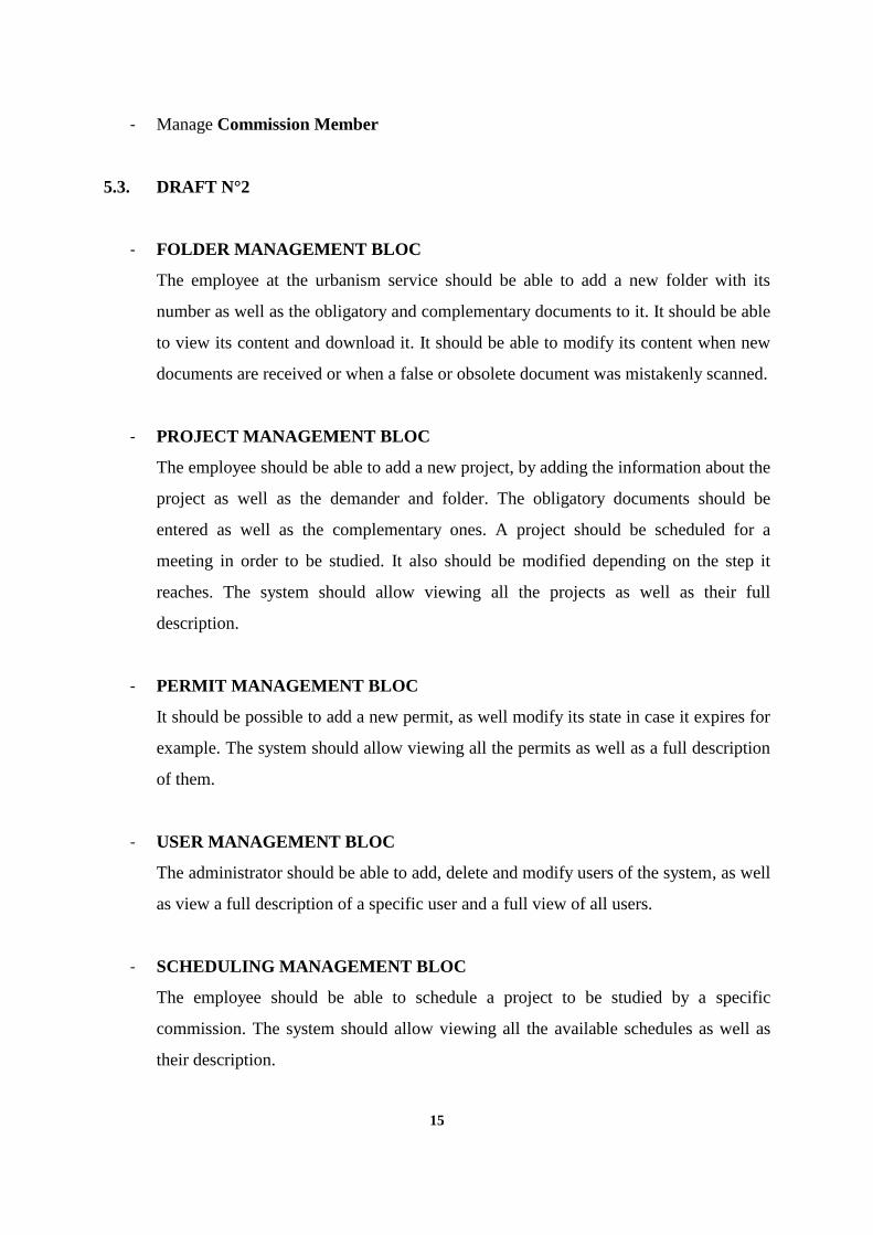
- FOLDER MANAGEMENT BLOC
The employee at the urbanism service should be able to add a new folder with its
number as well as the obligatory and complementary documents to it. It should be able
to view its content and download it. It should be able to modify its content when new
documents are received or when a false or obsolete document was mistakenly scanned.
- PROJECT MANAGEMENT BLOC
The employee should be able to add a new project, by adding the information about the
project as well as the demander and folder. The obligatory documents should be
entered as well as the complementary ones. A project should be scheduled for a
meeting in order to be studied. It also should be modified depending on the step it
reaches. The system should allow viewing all the projects as well as their full
description.
- PERMIT MANAGEMENT BLOC
It should be possible to add a new permit, as well modify its state in case it expires for
example. The system should allow viewing all the permits as well as a full description
of them.
- USER MANAGEMENT BLOC
The administrator should be able to add, delete and modify users of the system, as well
as view a full description of a specific user and a full view of all users.
- SCHEDULING MANAGEMENT BLOC
The employee should be able to schedule a project to be studied by a specific
commission. The system should allow viewing all the available schedules as well as
their description.

16
- COMMISSION MANAGEMENT BLOC
The system should allow adding, deleting, modifying a commission as well as viewing
a full description of its members.
- TAXATION MANAGEMENT BLOC
The system should allow calculating taxes related to a specific project, as well viewing
all the calculated taxes and a tax for a specific project’s description.
- DOCUMENT MANAGEMENT BLOC
The system should allow adding, deleting and modifying a document. It should also
allow viewing a specific document’s content as well as a description of all the
documents whiting a folder.
- MEETING MANAGEMENT BLOC
The system should allow adding individual inputs by different commission members
involved in a meeting and generating a common input that is either favorable or
unfavorable. It should allow viewing all decisions made in different meetings with a
full description as well as a full description for a specific decision.
- RECEIPT MANAGEMENT BLOC
The system should allow adding and printing different types of receipts, as well
viewing all receipts and their full description.
- AUTHENTICATION MANAGEMENT BLOC
The system should allow logging in and logging out using two credentials, depending
on the user type.
- STEP MANAGEMENT BLOC
The administrator should be able to add, modify and delete a step. The system should
allow viewing all the available steps with their descriptions as well as a full description
of a specific step.

17
- STATUS MANAGEMENT BLOC
The administrator should be able to add, modify and delete a status. The system should
allow viewing all the available statuses with their descriptions as well as a full
description of a specific status.
- SERVICE MANAGEMENT BLOC
The system should allow adding, deleting and modifying a service. It should allow
adding an employee to a service as well as assigning a head to it. It should allow
viewing all the available services with their full description and the full description of
a specific service with its employees.
- TRACEABILITY MANAGEMENT BLOC
The system should keep track of all the operations performed. It should automatically
add an entry specifying what was done by who and when. It should allow viewing all
the traces and their descriptions. It should also allow searching them by keyword.
- CITIZEN MANAGEMENT BLOC
The system should allow users of type citizen to view their profiles, their projects, and
their folders description and to view their documents as well search with a keyword.
- EMPLOYEE MANAGEMENT BLOC
The system should allow users of type employee to view their profiles, the ongoing
projects and their folders description, to view documents as well as to search with a
keyword, and move a project to its next step.
- TECHNICIAN MANAGEMENT BLOC
The system should allow users of type technician to view their profiles, the projects in
their control zones, as well their folders description and to view their documents as
well search with a keyword.
- ARCHITECT MANAGEMENT BLOC

18
The system should allow users of type architect to view their profiles, their projects,
and their folders description and to view their documents as well search with a
keyword.
- PRESIDENT MANAGEMENT BLOC
The system should allow users of type president to view their profiles, all projects, and
all folders description and to view all documents as well search with a keyword. It
should allow the president to approve or reject projects that are in that step.
- COMMISSION MEMBER MANAGEMENT BLOC
The system should allow users of type commission member to view their profiles, the
projects, and the folders description assigned to them for study and to view their
documents. It should allow them to enter an individual input on a specific project.
5.4. STABLE VERSION
5.4.1. FUNCTIONAL REQUIREMENTS
- FUNCTION MANAGE FOLDER
Sub Function Add new folder
Sub Function Modify folder
Sub Function View all folders description
Sub Function View specific folders description and content
Sub Function Add a document to a folder
Sub Function Search a document
- FUNCTION MANAGE PROJECT
Sub Function Add new project
Sub Function Modify project’s step
Sub Function Modify project’s status.
Sub Function View All projects description

19
Sub Function View specific projects description
Sub Function Add citizen to project
Sub Function Add folder to project
Sub Function Search project
- FUNCTION MANAGE PERMIT
Sub Function Add new permit
Sub Function Modify permit’s state
Sub Function View all permits description
Sub Function View a specific permit’s description
Sub Function Search a permit
- FUNCTION MANAGE USER
Sub Function Add new user
Sub Function Modify user
Sub Function Delete user
Sub Function View all users description
Sub Function View a specific user’s description
Sub Function Search a user
- FUNCTION MANAGE SCHEDULING
Sub Function Add new schedule
Sub Function Modify schedule
Sub Function Delete schedule
Sub Function View all schedules description
Sub Function View a specific schedule’s description
Sub Function Search a schedule
- FUNCTION MANAGE COMMISSION
Sub Function Add new commission
Sub Function Modify commission
20
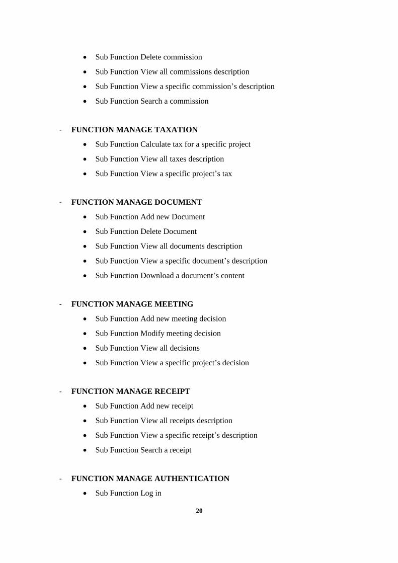
Sub Function Delete commission
Sub Function View all commissions description
Sub Function View a specific commission’s description
Sub Function Search a commission
- FUNCTION MANAGE TAXATION
Sub Function Calculate tax for a specific project
Sub Function View all taxes description
Sub Function View a specific project’s tax
- FUNCTION MANAGE DOCUMENT
Sub Function Add new Document
Sub Function Delete Document
Sub Function View all documents description
Sub Function View a specific document’s description
Sub Function Download a document’s content
- FUNCTION MANAGE MEETING
Sub Function Add new meeting decision
Sub Function Modify meeting decision
Sub Function View all decisions
Sub Function View a specific project’s decision
- FUNCTION MANAGE RECEIPT
Sub Function Add new receipt
Sub Function View all receipts description
Sub Function View a specific receipt’s description
Sub Function Search a receipt
- FUNCTION MANAGE AUTHENTICATION
Sub Function Log in

21
Sub Function Log out
- FUNCTION MANAGE STEP
Sub Function Add new step
Sub Function Modify step
Sub Function View all steps description
Sub Function View a specific step’s description
- FUNCTION MANAGE STATUS
Sub Function Add new status
Sub Function Modify status
Sub Function View all statuses description
Sub Function View a specific status’s description
- FUNCTION MANAGE SERVICE
Sub Function Add new service
Sub Function Modify service
Sub Function Delete service
Sub Function Add employee to service
Sub Function Assign a head to service
Sub Function Delete employee from service
Sub Function View all services description
Sub Function View a specific service’s employees
- FUNCTION MANAGE TRACEABILITY
Sub Function Automatically add new history
Sub Function View all history
Sub Function Search for history
- FUNCTION MANAGE CITIZEN
Sub Function Authenticate

22
Sub Function View profile
Sub Function View all projects
Sub Function View a specific project
Sub Function View all folders
Sub Function View a specific folder’s content
Sub Function View all documents
Sub Function Download a specific document’s content
Sub Function Search a project
Sub Function Search a folder
Sub Function Log out
- FUNCTION MANAGE EMPLOYEE
Sub Function Authenticate
Sub Function Add new project
o Sub-Sub Function Add project’s information
o Sub-Sub Function Add citizen’s information
o Sub-Sub Function Add folder’s documents
Sub Function Schedule a project
Sub Function View all projects description
Sub Function View a specific project’s description
Sub Function View all folders description
Sub Function View a specific folder’s description and content
Sub Function Download a document
Sub Function Download a receipt
Sub Function Notify users
Sub Function View all commissions
Sub Function View a specific commission’s description
Sub Function View all taxes
Sub Function View a specific project’s tax
Sub Function View all permits
Sub Function View a specific permit’s description

23
Sub Function Log out
- FUNCTION MANAGE TECHNICIAN
Sub Function Authenticate
Sub Function View profile
Sub Function View all projects
Sub Function View a specific project
Sub Function View all folders
Sub Function View a specific folder’s content
Sub Function View all documents
Sub Function Download a specific document’s content
Sub Function Search a project
Sub Function Search a folder
Sub Function Log out
- FUNCTION MANAGE ARCHITECT
Sub Function Authenticate
Sub Function View profile
Sub Function View all projects
Sub Function View a specific project
Sub Function View all folders
Sub Function View a specific folder’s content
Sub Function View all documents
Sub Function Download a specific document’s content
Sub Function Search a project
Sub Function Search a folder
Sub Function Log out
- FUNCTION MANAGE PRESIDENT
Sub Function Authenticate
Sub Function View all projects description

24
Sub Function View a specific project’s description
Sub Function View all folders description
Sub Function View a specific folder’s description and content
Sub Function Download a document
Sub Function Download a receipt
Sub Function View all commissions
Sub Function View a specific commission’s description
Sub Function View all taxes
Sub Function View a specific project’s tax
Sub Function View all permits
Sub Function View a specific permit’s description
Sub Function Validate a specific project
Sub Function Reject a specific project with a justifying note
Sub Function Log out
- FUNCTION MANAGE COMMISSION MEMBER
Sub Function Authenticate
Sub Function View all scheduled meetings
Sub Function View a specific scheduled meeting’s description
Sub Function View all projects description
Sub Function View a specific project’s description
Sub Function View all folders description
Sub Function View a specific folder’s description and content
Sub Function Download a document
Sub Function Add individual input
Sub Function Log out
5.4.2. NON-FUNCTIONAL REQUIREMENTS
- The system should be in both Arabic and French.
- The interface must be simple and easy to use.

25
- The system should be web based and accessible through a browser.

26
6 WORKFLOW ACTIVITY DIAGRAM
Figure 1 Workflow Activity Diagram
27
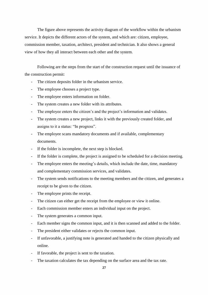
The figure above represents the activity diagram of the workflow within the urbanism
service. It depicts the different actors of the system, and which are: citizen, employee,
commission member, taxation, architect, president and technician. It also shows a general
view of how they all interact between each other and the system.
Following are the steps from the start of the construction request until the issuance of
the construction permit:
- The citizen deposits folder in the urbanism service.
- The employee chooses a project type.
- The employee enters information on folder.
- The system creates a new folder with its attributes.
- The employee enters the citizen’s and the project’s information and validates.
- The system creates a new project, links it with the previously created folder, and
assigns to it a status: “In progress”.
- The employee scans mandatory documents and if available, complementary
documents.
- If the folder is incomplete, the next step is blocked.
- If the folder is complete, the project is assigned to be scheduled for a decision meeting.
- The employee enters the meeting’s details, which include the date, time, mandatory
and complementary commission services, and validates.
- The system sends notifications to the meeting members and the citizen, and generates a
receipt to be given to the citizen.
- The employee prints the receipt.
- The citizen can either get the receipt from the employee or view it online.
- Each commission member enters an individual input on the project.
- The system generates a common input.
- Each member signs the common input, and it is then scanned and added to the folder.
- The president either validates or rejects the common input.
- If unfavorable, a justifying note is generated and handed to the citizen physically and
online.
- If favorable, the project is sent to the taxation.
- The taxation calculates the tax depending on the surface area and the tax rate.

28
- The payment permit and the public domain occupation documents are generated.
- The employee prints both and hands them to the citizen.
- The citizen pays and brings them both signed, with a receipt.
- All documents are scanned.
- The system informs the architect and the architect signs all the folder’s documents.
- The system generates the construction permit.
- The president signs the construction permit.
- The employee scans the construction permit.
- The citizen can get it from the employee and view it online and print it.
29
7 USERS VS SYSTEM ACTIVITY DIAGRAMS
7.1 Citizen Vs System
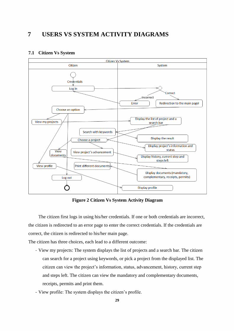
Figure 2 Citizen Vs System Activity Diagram
The citizen first logs in using his/her credentials. If one or both credentials are incorrect,
the citizen is redirected to an error page to enter the correct credentials. If the credentials are
correct, the citizen is redirected to his/her main page.
The citizen has three choices, each lead to a different outcome:
- View my projects: The system displays the list of projects and a search bar. The citizen
can search for a project using keywords, or pick a project from the displayed list. The
citizen can view the project’s information, status, advancement, history, current step
and steps left. The citizen can view the mandatory and complementary documents,
receipts, permits and print them.
- View profile: The system displays the citizen’s profile.

30
- Log out.
7.2 Employee Vs System
Figure 3 Employee Vs System
The employee first logs in using his/her credentials. If one or both credentials are
incorrect, the employee is redirected to an error page to enter the correct credentials. If the
credentials are correct, the employee is redirected to his/her main page.
The employee has five choices, each lead to a different outcome:
- Enter new project’s details: The employee enters the project’s and citizen’s information
and links it to a previously created folder.
- Choose ongoing project: The employee can either validate a project, so that the system
moves it to the next step. He/she can print a document from a project, such as a permit
or a receipt. He/she can modify a project’s details.
- View profile: The system displays the employee’s profile.

31
- Search: The employee can search for a project using keywords.
- Log out.
7.3 Commission Vs System
Figure 4 Commission Vs System
The commission member first logs in using his/her credentials. If one or both credentials
are incorrect, the commission member is redirected to an error page to enter the correct
credentials. If the credentials are correct, the commission member is redirected to his/her main
page.
The commission member has three choices, each lead to a different outcome:
- Choose a scheduling: The system displays the project’s information. The member enters
his/her individual input and validates.
- View profile: The system displays the commission member’s profile.
- Log out.

32
7.4 Taxation Vs System
Figure 5 Taxation Vs System
The taxation employee first logs in using his/her credentials. If one or both credentials
are incorrect, the taxation employee is redirected to an error page to enter the correct
credentials. If the credentials are correct, the taxation employee is redirected to his/her main
page.
The taxation employee has three choices, each lead to a different outcome:
- View projects to be taxed: The system displays the list of projects and a search bar. The
employee can choose a project and calculate the taxes. The employee can search a
project using keywords.
- View profile: The system displays the taxation employee’s profile.
- Log out.

33
7.5 Architect Vs System
Figure 6 Architect Vs System
The architect first logs in using his/her credentials. If one or both credentials are
incorrect, the architect is redirected to an error page to enter the correct credentials. If the
credentials are correct, the architect is redirected to his/her main page.
The architect has four choices, each lead to a different outcome:
- View my projects: The system displays the list of projects and a search bar. The architect
can choose a project and view its information and status. He/she can also search for a
project using keywords.
- Create project: The architect enters the project’s and citizen’s information then validates.
The system add the projects with an ID to the database.
- View profile: The system displays the architect’s profile.
- Log out.

34
7.6 President Vs System
Figure 7 President Vs System
The president first logs in using his/her credentials. If one or both credentials are
incorrect, the president is redirected to an error page to enter the correct credentials. If the
credentials are correct, the president is redirected to his/her main page.
The president has four choices, each lead to a different outcome:
- View projects that need a signature: The system displays a list of projects and a search
bar. The president can choose a project and display its information and status. He/she
can then decide whether to sign it or not. The president can also search for a project
using keywords.
- View projects’ information, advancement and folder content: The system displays a list
of projects and a search bar. The president can choose a project and display its
information and status. The president can also search for a project using keywords.
- View profile: The system displays the president’s profile.

35
- Log out.
7.7 Technician Vs System
Figure 8 Technician Vs System
The technician first logs in using his/her credentials. If one or both credentials are
incorrect, the technician is redirected to an error page to enter the correct credentials. If the
credentials are correct, the technician is redirected to his/her main page.
The technician has three choices, each lead to a different outcome:
- View projects in my control zone: The system displays the list of projects and a search
bar. The technician can search for a project using keywords, or pick a project from the
displayed list. The technician can view the project’s information and status.
- View profile: The system displays the citizen’s profile.
- Log out.

36
7.8 Admin Vs System
Figure 9 Admin Vs System
The administrator first logs in using his/her credentials. If one or both credentials are
incorrect, the administrator is redirected to an error page to enter the correct credentials. If the
credentials are correct, the administrator is redirected to his/her main page.
The administrator has three choices, each lead to a different outcome:
- Create account/profile, modify or delete: The administrator enters the details and
validates, or deletes. The system updates the database.
- Create, modify or delete a service: The administrator can enter the details of a service,
assign a director and add employees. He/she can also delete it. The system updates the
database.
- Log out.

37
8 DATA MODELLING
8.1. CONCEPTUAL DATA MODEL
8.1.1. Procedure
The conceptual data model is a high level representation of the data used in the
business. It is described as a high level representation in the sense that it does not involve
technical details related to the implementation. Its purpose is to give a global and clear view of
the different entities of the business, as well the relationships between each one of them.
In order to obtain the different entities, the relationships between them and the
generation of the Entity Relation Diagram (ERD), the MERISE methodology was used. The
first step was the data gathering. Two main approaches were used: The deductive approach
and the inductive approach.
The deductive approach or top-down approach moves from the general to the
particular. In this case, it consisted of conducting interviews with the employees in Sefrou, in
order to get the information on how the business works, and analyze it to get the specific data.
The interviews were a set of questions that aimed at achieving the elicitation of the ambiguous
and sometimes contradictory information collected, in order to obtain concise, precise and
complete data after analyzing the information. The purpose was to understand the
relationships between the different possible entities. For example, the employee would say
they work with folders, which is general, and with directed questions we conclude that a folder
has an ID, a set of documents, and belongs to a specific citizen.
The inductive approach or bottom-up approach moves from the particular and specific
to the general. This approach first involves gathering documents and other evidence from the
business or organization and extracting the data that is fields without meaning. After that, all
these meaningless fields are organized in a “dictionary” and the main anomalies which are:
synonymy, redundancy and homonymy are getting rid of. Synonymy means that two or more
38
fields have different names but have the same purpose (example: first name and prénom).
Redundancy means that two or more fields have the same name and the same purpose
(example: first name and first name). Homonymy means that two or more fields have the same
name but different purposes (example: first name on a document might concern the citizen
and first name on another document might concern the architect). The following step was to
gather those fields and derive any possible entities from them. The data was derived from a set
of documents in Arabic that contained the urbanism’s “Official Journal” that contains general
texts describing the different rules governing several cases’ procedures, as well as the
documents they use for issuing receipts, permits, taxation, commission decisions, demands
etc.
8.1.2. Results
Identification and Description of the Entities
There are 19 entities:
- Architect: This entity represents the architects of the project. There are three types: the
building architect, the specialized architect and the topographic architect. Its attributes
are: Title, a First Name and a Last Name.
- Building: This entity represents the building that is involved in the project. Depending
on the type of the project, the attributes of this entity either get a value or remain null.
Its attributes are: Basement, Ground Floor, First Floor, Second Floor, Mezzanine and
Balconies.
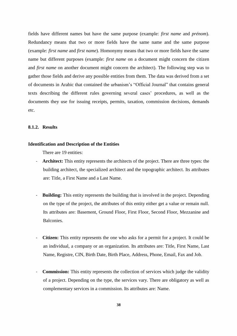
- Citizen: This entity represents the one who asks for a permit for a project. It could be
an individual, a company or an organization. Its attributes are: Title, First Name, Last
Name, Registre, CIN, Birth Date, Birth Place, Address, Phone, Email, Fax and Job.
- Commission: This entity represents the collection of services which judge the validity
of a project. Depending on the type, the services vary. There are obligatory as well as
complementary services in a commission. Its attributes are: Name.
39
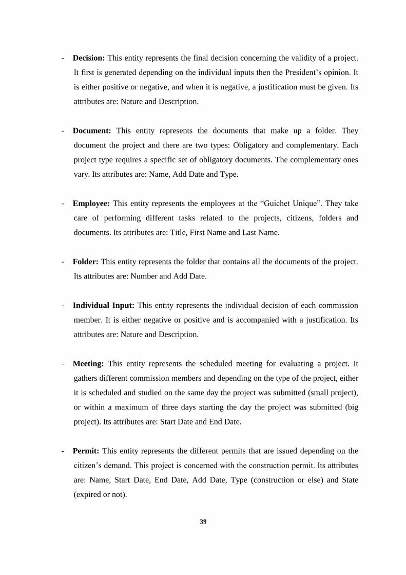
- Decision: This entity represents the final decision concerning the validity of a project.
It first is generated depending on the individual inputs then the President’s opinion. It
is either positive or negative, and when it is negative, a justification must be given. Its
attributes are: Nature and Description.
- Document: This entity represents the documents that make up a folder. They
document the project and there are two types: Obligatory and complementary. Each
project type requires a specific set of obligatory documents. The complementary ones
vary. Its attributes are: Name, Add Date and Type.
- Employee: This entity represents the employees at the “Guichet Unique”. They take
care of performing different tasks related to the projects, citizens, folders and
documents. Its attributes are: Title, First Name and Last Name.
- Folder: This entity represents the folder that contains all the documents of the project.
Its attributes are: Number and Add Date.
- Individual Input: This entity represents the individual decision of each commission
member. It is either negative or positive and is accompanied with a justification. Its
attributes are: Nature and Description.
- Meeting: This entity represents the scheduled meeting for evaluating a project. It
gathers different commission members and depending on the type of the project, either
it is scheduled and studied on the same day the project was submitted (small project),
or within a maximum of three days starting the day the project was submitted (big
project). Its attributes are: Start Date and End Date.
- Permit: This entity represents the different permits that are issued depending on the
citizen’s demand. This project is concerned with the construction permit. Its attributes
are: Name, Start Date, End Date, Add Date, Type (construction or else) and State
(expired or not).
40
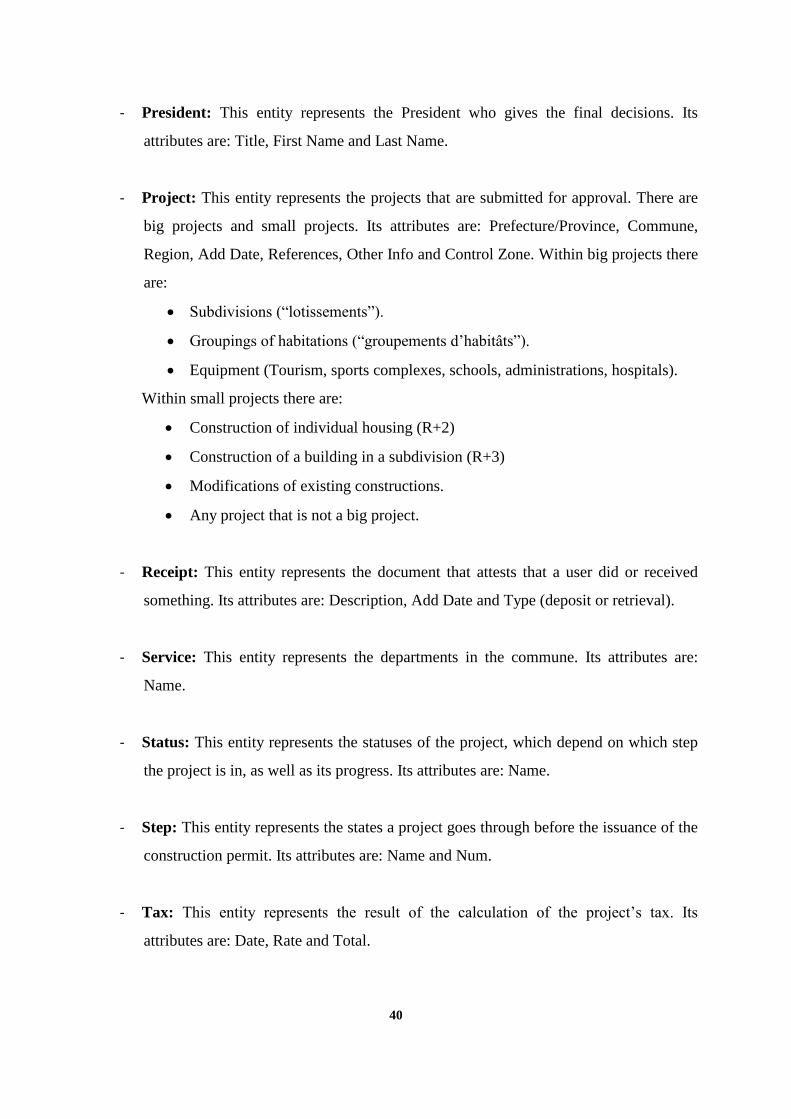
- President: This entity represents the President who gives the final decisions. Its
attributes are: Title, First Name and Last Name.
- Project: This entity represents the projects that are submitted for approval. There are
big projects and small projects. Its attributes are: Prefecture/Province, Commune,
Region, Add Date, References, Other Info and Control Zone. Within big projects there
are:
Subdivisions (“lotissements”).
Groupings of habitations (“groupements d’habitâts”).
Equipment (Tourism, sports complexes, schools, administrations, hospitals).
Within small projects there are:
Construction of individual housing (R+2)
Construction of a building in a subdivision (R+3)
Modifications of existing constructions.
Any project that is not a big project.
- Receipt: This entity represents the document that attests that a user did or received
something. Its attributes are: Description, Add Date and Type (deposit or retrieval).
- Service: This entity represents the departments in the commune. Its attributes are:
Name.
- Status: This entity represents the statuses of the project, which depend on which step
the project is in, as well as its progress. Its attributes are: Name.
- Step: This entity represents the states a project goes through before the issuance of the
construction permit. Its attributes are: Name and Num.
- Tax: This entity represents the result of the calculation of the project’s tax. Its
attributes are: Date, Rate and Total.
41
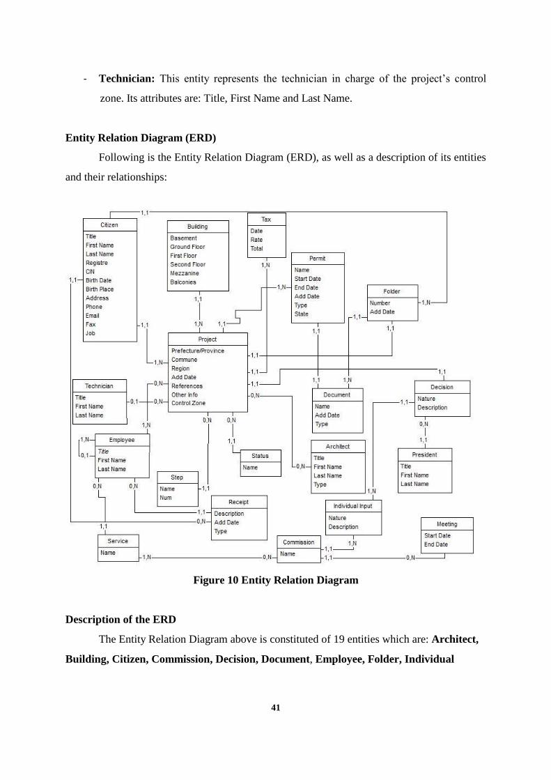
- Technician: This entity represents the technician in charge of the project’s control
zone. Its attributes are: Title, First Name and Last Name.
Entity Relation Diagram (ERD)
Following is the Entity Relation Diagram (ERD), as well as a description of its entities
and their relationships:
Figure 10 Entity Relation Diagram
Description of the ERD
The Entity Relation Diagram above is constituted of 19 entities which are: Architect,
Building, Citizen, Commission, Decision, Document, Employee, Folder, Individual

42
Input, Meeting, Permit, President, Project, Receipt, Service, Status, Step, Tax and
Technician. We have 23 relations:
- Project and Building: Project involves Building and Building is contained in Project.
One Project could involve One Building and One Building can be contained in One
Project.
- Tax and Project: Tax is calculated from Project and Project has Tax. One Tax is
calculated for One Project and One Project can have One Tax.
- Project and Folder: Project has Folder and Folder is for Project. One Project could
involve One Folder and One Folder can be contained in One Project.
- Document and Folder: Document is contained in Folder and Folder contains
Document. Many Documents can be contained in One Folder and One Folder can
contain Many Documents.
- Project and Step: Project reaches Step and Step can be reached by Project. Many
Projects can reach One Step and One Step can be reached by Many Projects.
- Project and Status: Project has Status and Status describes Project. Many Projects
have One Status and One Status can describe Many Projects.
- Project and Architect: Project has Architect and Architect has Project. Many
Projects have Many Architects and Many Architects have Many Projects.
- Decision and President: Decision is made by President and President makes
Decision. Many Decisions are made by One President and One President makes
Many Decisions.

43
- Project and Decision: Project is concerned with Decision and Decision is made on
Project. One Project is concerned with One Decision and One Decision is made on
One Project.
- Project and Technician: Project has Technician and Technician has Project. Many
Projects have One Technician and One Technician has Many Projects.
- Employee and Project: Employee follows Project and Project is followed by
Employee. One Employee follows Many Projects and Many Projects are followed by
One Employee.
- Employee and Receipt: Employee gives Receipt and Receipt is given by Employee.
One Employee gives Many Receipts and Many Receipts are given by One Employee.
- Receipt and Citizen: Receipt is given to Citizen and Citizen gets Receipt. Many
Receipts are given to One Citizen and One Citizen receives Many Receipts.
- Employee and Service: Employee belongs to Service and Service includes Employee.
Many Employees belong to One Service and One Service includes Many Employees.
- Service and Commission: Service is included in Commission and Commission
includes Service. Many Services are included in Many Commissions and Many
Commissions include Many Services.
- Individual Input and Decision: Individual Input affects Decision and Decision is
affected by Individual Input. Many Individual Inputs affect One Decision and One
Decision is affected by Many Individual Inputs.
- Meeting and Commission: Meeting includes Commission and Commission is
involved in Meeting. Many Meetings include One Commission and One Commission
is involved in Many Meetings.

44
- Permit and Project: Permit is given to Project and Project is given Permit. Many
Permits can be given to One Project and One Project can be given Many Permits.
- Permit and Document: Permit is represented by Document and Document represents
Permit. One Permit is represented by One Document and One Document represents
One Permit.
- Individual Input and Commission: Individual Input is given by Commission and
Commission gives Individual Input. Many Individual Inputs are given by One
Commission and One Commission gives Many Individual Inputs.
- Folder and Citizen: Folder belongs to Citizen and Citizen has Folder. Many Folders
belong to One Citizen and One Citizen has Many Folders.
- Employee and Employee: Employee is the superior of Employee and Employee is
under Employee. One Employee is the superior of Many Employees and Many
Employees are under One Employee.
- Project and Citizen: Project belongs to Citizen and Citizen has Project. Many
Projects belong to One Citizen and One Citizen has Many Projects.
8.2. PHYSICAL DATA MODEL
8.2.1. Procedure
The physical data model is the representation of how the database is to be
implemented. Unlike the conceptual data model, it takes into consideration the technical side
of the data. It shows how the tables are structured, the names of the columns, their types, the
constraints if any (example: unique), the primary key, the foreign keys, the relationships
between tables (one to one, one to many) and the bridge tables in case of many to many
relationships.

45
The following Enhanced Entity Relation Diagram was obtained by converting the
entities present in the conceptual data model into tables, converting the relationships between
entities into foreign keys, converting entities’ attributes into columns, assigning data types to
them according to the technical requirements, and updating it considering any constraints.
This diagram is accompanied by a description of the tables and relationships.
8.2.1. Enhanced Entity Relation Diagram

46
Figure 11 Enhanced Entity Relation Diagram

47
- Division: This represents the entity Service. It has three columns:
Id: Primary key. BIGINT (20).
Name: VARCHAR(255). This represents the name of the division. It depends
on the commune’s divisions.
Head_id: Foreign key. BIGINT(20). This represents the head of a division,
which is a User of type Employee or President. It links this table with the
table User using a One-To-One relationship.
- Receipttype: This represents the entity Receipt Type. It has two columns:
Id: Primary Key. BIGINT(20).
Type: VARCHAR(255). This represents the name of the type, which is either
Deposit or Retrieval.
- Com_Serv: This is a bridge table between Commission and Division. It has two
columns:
Com_Id: Foreign key. BIGINT(20). This links this table to the table
Commission by a Many-To-One relationship.
Serv_Id: Foreign key. BIGINT(20). This links this table to the table Division
by a Many-To-One relationship.
- Notificationtype: This represents the entity Notification Type. It has two columns:
Id: Primary Key. BIGINT(20).
Type: VARCHAR(255). This represents the name of the type.
- Commission: This represents the entity Commission. It has two columns:
Id: Primary Key. BIGINT(20).
Name: VARCHAR(255). This represents the name of the commission. It
reflects the type of the project to be judged.
- Tax: This represents the entity Tax. It has ten columns:

48
Id: Primary Key. BIGINT(20).
Rate: DOUBLE. This represents the tax rate.
addDate: DATETIME. This represents the date and time the tax was
generated.
Total: DOUBLE. This represents the total surface area.
Proj_Id: Foreign key. BIGINT(20). This represents the project for which the
tax is being calculated. It links this table with the table Project using a Many-
To-One relationship
- Projecttype: This represents the entity Project Type. It has two columns:
Id: Primary Key. BIGINT(20).
Type: VARCHAR(255). This represents the name of the type. In the case of a
big project, this can be “Lotissement”, “Groupement d’Habitat”,”
Equipements”.
- Project: This represents the entity Project. It has twenty-nine columns:
TYPE: VARCHAR(25). This represents the types of the Project, and which
are BIG or SMALL.
Id: Primary key. BIGINT(20).
Address: VARCHAR(255). This represents the address of the building to be
constructed.
Commune: VARCHAR(255). This represents the commune under which the
project is to be registered.
depositDate: VARCHAR(255). This represents the date the project was
deposited.
otherInfo: VARCHAR(255). This represents any additional information not
present in any other field.
prefOrProv: VARCHAR(255). This represents the prefecture or the province
to which the project belongs.
Refs: VARCHAR(255). This represents the project’s references.
49
Region: VARCHAR(255). This represents the region the project is to construct
in.
Step: Foreign key. BIGINT(20). This represents the step in which the project
is. It links this table with the table Step using a Many-To-One relationship.
Subject: VARCHAR(255). This represents the subject of the project.
delayDecMax: INT(11). This represents the number of maximum days before
a decision on the project is made.
delayProgMax: INT(11). This represents the number of maximum days before
a meeting to judge a project is made.
infoDoc: LONGBLOB. This represents a document that describes the type of
the project.
infoTxt: VARCHAR(255). This represents a text that references the real life
document used to extract the type of the project’s attributes.
Archm_Id: Foreign key. BIGINT(20). This represents the architect of the
project. It links this table with the table User using a One-To-One relationship.
Archs_Id: Foreign key. BIGINT(20). This represents the specialized architect
of the project. It links this table with the table User using a One-To-One
relationship.
Archt_Id: Foreign key. BIGINT(20). This represents the topographic architect
of the project. It links this table with the table User using a One-To-One
relationship.
Decision_Id: Foreign key. BIGINT(20). This represents the decision about the
project’s viability. It links this table with the table Decision using a One-To-
One relationship.
Demander_Id: Foreign key. BIGINT(20). This represents the demander
(citizen) of the project, the one who wants the construction permit. It links this
table with the table User using a One-To-One relationship.
Folder_Id: Foreign key. BIGINT(20). This represents the folder of the project.
It links this table with the table Folder using a One-To-One relationship.
Status_Id: Foreign key. BIGINT(20). This represents the status of the project.
It links this table with the table Status using a Many-To-One relationship.

50
Type_Id: Foreign key. BIGINT(20). This represents the type of the type of
project. It is different from the column “TYPE”. It links this table with the
table Projecttype using a Many-To-One relationship.
Balconies: DOUBLE. This represents the total surface of all the balconies.
Basement: DOUBLE. This represents the total surface of the basement.
firstFloor: DOUBLE. This represents the total surface of the first floor.
groundFloor: DOUBLE. This represents the total surface of the ground floor.
Mezzanine: DOUBLE. This represents the total surface of the mezzanine.
secondFloor: DOUBLE. This represents the total surface of the second floor.
- Usertype: This represents the entity User Type. It has two columns:
Id: Primary Key. BIGINT(20).
Type: VARCHAR(255). This represents the name of the type. It can be either
Citizen, Employee, ArchitectM, ArchitectS, ArchitectT, President, Technician,
Commission(member), Taxation or Administrator.
- Folder: This represents the entity Folder. It has five columns:
Id: Primary Key. BIGINT(20).
addDate: DATETIME. This represents the date and time the folder was added
to the system.
Num: VARCHAR(255). This represents the identifier number of the folder.
Project_Id: Foreign key. BIGINT(20). This represents the project to which the
folder belongs. It links this table with the table Project using a One-To-One
relationship.
User_Id: Foreign key. BIGINT(20). This represents the user to which the
folder belong. It links this table with the table User using a Many-To-One
relationship.
- Step: This represents the entity Step. It has four columns:
Num: Primary key. INT(11).
51
Name: VARCHAR(255). This represents the name of the step. There are six
steps.
State: INT(11). This represents whether the step was completed.
Proj_Id: Foreign key. BIGINT(20). This represents the project that is at that
step. It links this table with the table Project using a One-To-One relationship.
- Notification: This represents the entity Notification. It has six columns:
Id: Primary key. BIGINT(20).
addDate: DATETIME. This represents the date and the time the notification is
sent.
Text: VARCHAR(255). This represents the actual message in the notification.
Receiver_Id: Foreign key. BIGINT(20). This represents the receiver to which
the notification is sent. It links this table with the table User using a Many-To-
One relationship.
Sender_Id: Foreign key. BIGINT(20). This represents the sender by whom the
notification is sent. It links this table with the table User using a Many-To-
One relationship.
Type_Id: Foreign key. BIGINT(20). This represents the type of the
notification. It links this table with the table Notificationtype using a Many-
To-One relationship.
- Document: This represents the entity Document. It has eight columns:
TYPE: VARCHAR(25). This represents the types of the Document, and
which are many and depend on the commune.
Id: Primary key. BIGINT(20).
addDate: DATETIME. This represents the date and time the document is
added to the system.
Document: LONGBLOB. This represents the actual document, either a PDF or
an image or else.
Name: VARCHAR(255). This represents the name of the document.
Info: VARCHAR(255). This represents the info on the document.

52
Folder_Id: Foreign key. BIGINT(20). This represents the folder to which the
document belongs. It links this table with the table Folder using a Many-To-
One relationship.
Type_Id: Foreign key. BIGINT(20). This represents the type of the document,
whether it is Obligatory or Complementary. It links this table with the table
Documenttype using a Many-To-One relationship.
- Receipt: This represents the entity Receipt. It has five columns:
Id: Primary key. BIGINT(20).
addDate: DATETIME. This represents the date and the time the receipt was
sent.
Text: VARCHAR(255). This represents the actual content of the receipt.
Receiver_Id: Foreign key. BIGINT(20). This represents the receiver of the
receipt. It links this table with the table User using a Many-To-One
relationship.
Type_Id: Foreign key. BIGINT(20). This represents the type of the receipt. It
links this table with the table Receipttype using a Many-To-One relationship.
- History: This represents the entity History. It has six columns:
Id: Primary key. BIGINT(20).
addDate: DATETIME. This represents the date and time the system generates
the history.
Folder_Id: Foreign key. BIGINT(20). This represents the folder recorded in
the history. It links this table with the table Folder using a Many-To-One
relationship.
Proj_Id: Foreign key. BIGINT(20). This represents the project recorded in the
history. It links this table with the table Project using a Many-To-One
relationship.
Step_Id: Foreign key. BIGINT(20). This represents the step recorded in the
history. It links this table with the table Step using a Many-To-One
relationship.

53
User_Id: Foreign key. BIGINT(20). This represents the user recorded in the
history. It links this table with the table User using a Many-To-One
relationship..
- Documenttype: This represents the entity Document Type. It has two columns:
Id: Primary Key. BIGINT(20).
Type: VARCHAR(255). This represents the name of the type. It can be either
Obligatory and Complementary.
- Indivinput: This represents the Individual Inputs which represent the commission
members’ opinion on a given project. It has seven columns:
Id: Primary Key. BIGINT(20).
Comment: VARCHAR (255).
Result: BIT(1). This represent whether the individual input was negative or
positive (0 or 1).
Decision_Id: Foreign key. BIGINT(20). This represents the decision this
individual input along with other individual inputs led to. It links this table
with the table Decision using a Many-To-One relationship.
Meeting_Id: Foreign key. BIGINT(20). This represents the meeting that led to
this individual input. It links this table with the table Meeting using a Many-
To-One relationship.
Proj_Id: Foreign key. BIGINT(20). This represents the project to which the
individual input belongs. It links this table with the table Project using a
Many-To-One relationship.
User_Id: Foreign key. BIGINT(20). This represents the user that writes the
individual input. It links this table with the table User using a Many-To-One
relationship.
- Meeting: This represents the entity Meeting. It has six columns:
Id: Primary Key. BIGINT(20).
endDate: DATETIME. This represents the end date and time of the meeting.

54
startDate: DATETIME. This represents the start date and time of the meeting.
Decision_Id: Foreign key. BIGINT(20). This represents the decision that is
generated from the meeting. It links this table with the table Decision using a
One-To-One relationship.
Project_Id: Foreign key. BIGINT(20). This represents the project the meeting
is held for. It links this table with the table Project using a Many-To-One
relationship.
Schedule_Id: Foreign key. BIGINT(20). This represents the schedule that
organized the meeting. It links this table with the table Schedule using a One-
To-One relationship.
- Permittype: This represents the entity Permit Type. It has two columns:
Id: Primary Key. BIGINT(20).
Type: VARCHAR(255). This represents the name of the type.
- Status: This represents the entity Status. It has two columns:
Num: Primary key. INT(11).
Status: VARCHAR (255). This represents the name of the status.
- User: This represents the entity User. It has nineteen columns:
DTYPE: This represents the type of the user, which could be Citizen,
Employee, ArchitectM, ArchitectS, ArchitectT, President, Technician,
Commission(member), Taxation or Administrator. It links this table with the
table Usertype using a Many-To-One relationship.
Id: Primary Key. BIGINT(20).
Address: VARCHAR (255). This represents the address of the user.
birthdate: VARCHAR (255). This represents the birth date of the user.
birthPlace: VARCHAR (255). This represents the birth place of the user.
CIN: VARCHAR (255). This represents the national ID card number of the
user.
Email: VARCHAR (255). This represents the email of the user.

55
Fax: VARCHAR (255). This represents the fax number of the user.
Fname: VARCHAR (255). This represents the first name of the user.
Job: VARCHAR (255). This represents the job of the user.
Lname: VARCHAR (255). This represents the last name of the user.
Password: VARCHAR (255). This represents the password of the user.
Phone: VARCHAR (255). This represents the phone number of the user.
Registre: VARCHAR (255). This represents the register of the user.
Title: VARCHAR (255). This represents the title of the user (Mr. Mrs. Miss
etc).
Username: VARCHAR (255). This represents the username of the user.
Serv_Id: Foreign key. BIGINT(20). This represents the division the user works
for. It links this table with the table Division using a Many-To-One
relationship.
- Permit: This represents the entity Permit. It has eight columns:
Id: Primary Key. BIGINT(20).
addDate: DATETIME. This is the date the permit is added.
endDate: DATETIME. This is the date the permit expires.
startDate: DATETIME. This is the date the permit starts to be valid.
Document_Id: Foreign key. BIGINT(20). This represents the document form
of the permit. It links this table with the table Document using a One-To-One
relationship.
Proj_Id: Foreign key. BIGINT(20). This represents the project to which the
permit is issued. It links this table with the table Project using a Many-To-
One relationship.
Type_Id: Foreign key. BIGINT(20). This represents the type of the permit. It
links this table with the table Permittype using a Many-To-One relationship.
User_Id: Foreign key. BIGINT(20). This represents the user to whom the
permit is issued. It links this table with the table User using a Many-To-One
relationship.

56
- Decision: This represents the Decision concerning a given project, that is based on the
commission members individual inputs, as well the president’s opinion. It has six
columns:
Id: Primary Key. BIGINT(20).
Comment: VARCHAR (255). This represents the text decision, whether it is
favorable or unfavorable.
Result: BIT(1). This represents the nature of the decision. Positive or negative
(0 or 1).
Validated: BIT(1). This represents whether the president validated the result
from the members (0 or 1).
Meeting_Id: Foreign key. BIGINT(20). This represents the meeting that led to
the individual inputs that led to the decision. It links this table with the table
Meeting using a One-To-One relationship.
Project_Id: Foreign key. BIGINT(20). This represents the project that the
decision belongs to. It links this table with the table Project using a One-To-
One relationship.

57
9 DESIGN
9.1. SYSTEM ARCHITECTURE
9.1.1. Description
The architecture of this system is an N-Layered Architecture. An N-Layered
Architecture is what Enterprise Applications follow. It is mainly organized into multiple
layers, each responsible for a specific task. In general, it is composed of a Presentation
Layer, a Middle Layer and a Data Layer.
The Presentation Layer sits between the end users and the application. Through the
browser, they access it and interact with it. It consists of the views, the graphical user interface
and the dispatching servlet. It captures the input of the users, forwards it to the application for
processing, then if available, the application sends the output to this layer that displays it to the
users. The forwarding of data is possible through the Data Binding Components (for example,
field names with variable names) and the Object Representations of data present in this layer.
The Middle Layer, also called the Business Layer, sits between the first and the third
layer. They both communicate through this layer, and not directly with each other. It consists
of the Business Logic that follows the business rules and the business constraints, as well as
Data Access Components that allow the communication with the third layer. The end user is
not able to communicate directly with this layer, and should go through the presentation layer
in order to send or receive data through the browser thanks to a protocol.
The Data Layer is the third layer and it communicates with the middle layer. That
communication is allowed by an API (a database connectivity) present in the middle layer.
The data layer is typically a server that stores data (for example, MySQL), in the form of
databases. Those databases are a set of tables with columns and relationships (one-to-one,
one-to-many, many-to-many through bridge tables), in case of a relational database (which is
the case most of the time).

58
9.1.2. Advantages
The N-Layered Architecture has many advantages from which are the following:
- Easier Maintenance: Due to its layered structure, it is easier and less time consuming
to maintain. For example, if one layer needs enhancements or tune-ins, there is no need
to go through all the other layers in order to change or update it. Layers are
independent from each other but communicate with each other.
- Enhanced Security: It is less likely to suffer from security attacks due to the
separation of tasks between the layers, as well as restricting the possible threats
(malicious end-users) to have access to the middle or data layer, since they can only
interact with the presentation layer. It would require much more effort and time for a
hacker to bypass those restrictions.
- Enhanced Fault Tolerance: If one part of a layer goes down, the application does not
necessarily crash as well. Only the functionalities related to that part are disabled. Due
to it being modular, although one module goes down, the other modules can still be
operational.
- Enhanced Reusability: Its modular nature allows the different functionalities and
code to be reused in other applications. For example, the login is a standard module.
There is no need to reinvent the wheel when the application is modular.
9.2. TECHNOLOGY ENABLERS
9.2.1. IDE (Integrated Development Environment)
- Eclipse: It is written in Java and allows the development of Java applications as well
as others. It supports plug-ins that can greatly extend its features.

59
9.2.2. Web Container
- Tomcat: It is a free HTTP (HyperText Transfer Protocol) web container that belongs
to the Apache Software Foundation, and that was written in the Java language. It
executes within a Java Virtual Machine (JVM). It manages servlets and JSP using a
compiler called Jasper that compiles JSP into servlets, allowing dynamic web content
(getting input from the end-user for processing, and displaying the output to the end-
user).
9.2.3. Presentation and Web Layer
- HTML: It stands for HyperText Markup Language and is a language that allows
creating pages accessible on the internet using markup. It means that it uses tags to
render the content of the page (for example, the text font).
- Bootstrap: It is a very popular front-end (HTML/CSS/JS) framework for formatting
web pages content. It is free (open source) can be integrated in many development
environments.
- JavaScript: It is a dynamic and interpreted programming language. It allows the
creation of dynamic content (client-side script) for the end-user to interact with (for
example, a button that when it is clicked displays the time real-time).
- JSP: It stands for JavaServer Pages, and is used along with HTML and JavaScript to
generate dynamic web pages. It also plays the role of a servlet during execution-time,
captures the end-user input to be processed in the business layer and displays output.
- Spring MVC: It stands for Spring Model-View-Controller and is a framework that is
designed around what is called a “DispatcherServlet”, which dispatches requests to the
appropriate handlers. The DispatcherServlet receives a request with a URI-pattern. It
consults its handler mapping to select the controller which bean name is the URI-

60
pattern. It dispatches the request to the selected controller that returns to the
DispatcherServlet an object of type ModelandView that holds the logical name of the
view to display. The DispatcherServlet finds the view thanks to the
InternalResourceViewResolver, then forwards the request to it.
9.2.4. Business and DAO (Data Access Object) Layer
- Spring IOC: It stands for Spring Inversion of Control. It is a container that manages
dependencies injection (JPA, Hibernate, JDBC…), and which links implementation
classes to their interface classes. It uses 3 key elements which are: the XML
configuration that links the implementations to their interfaces, the classes that are
beans and that possess getters and setters for the fields to be injected, and the XML file
applicationContext.xml in which the injection is made. IOC uses annotations for
simplification.
- JPA: The Java Persistence API allows Object Relational Mapping, which means that it
maps the Java classes (entities) to tables in a database and vice-versa. A database can
be created out of Java classes and vice-versa. It relies on annotations that specify that a
class in an Entity (@Entity), as well as the relationships between them (@OneToOne),
and an instantiation of the EntityManager class which, as its name implies, manages
the entities and CRUD operations in the database.
- Hibernate: It is an implementation of JPA, since JPA is only a standard that sets the
rules to be followed to achieve Object Relational Mapping. JPA is the theory and
Hibernate is the practice.
- JDBC: It stands for Java DataBase Connectivity, and it is an API that enables
connecting and interacting with the database.

61
9.2.5. Data Layer
- MySQL: It is a database management system. Its purpose is to create, retrieve, update,
delete and manage data in a database.
9.3. ENHANCED SYSTEM ARCHITECTURE
Figure 12 Enhanced System Architecture
62
10 IMPLEMENTATION
The system is still under construction and so far is structured as follows:
Main xml files for configuration and dependency injection:
- applicationContext.xml
- persistence.xml
- servlet-context.xml
- web.xml
- log4j.xml
- pom.xml
Middle Layer packages and classes under org.projet.urbanisme:
- Entities:
Administrator.java
ArchitectM.java
ArchitectS.java
ArchitectT.java
Citizen.java
ComMember.java
Commission.java
Decision.java
Division.java
Document.java
DocumentType.java
Employee.java
Folder.java
History.java
IndivInput.java
Meeting.java
Notification.java
NotificationType.java
63
Permit.java
PermitType.java
President.java
Project.java
ProjectBig.java
ProjectSmall.java
ProjectType.java
Status.java
Step.java
Tax.java
Taxation.java
Technician.java
User.java
UserType.java
- Metier:
IUrbanMetier.java (Interface)
UrbanMetierImpl.java (Its implementation)
- DAO:
IUrbanDao.java (Interface)
UrbanDaoImpl.java (Its implementation)
- Models:
CitForm.java
ComForm.java
EmpForm.java
ProgForm.java
ProjectFrom.java
ServForm.java
UrbanForm.java
UserForm.java
- Controllers:
UrbanController.java

64
Presentation and Web Layer:
Under this part the JSP and/or html views are found, as well as any CSS style sheets or images
to be used in the views, as well the spring configuration files that allow mapping those
resources and enabling the communication between views, models and controllers.

65
11 MAIN CHALLENGES AND LESSONS LEARNED
The main challenges encountered during this capstone project are the following:
- Very little to inexistent knowledge about the urbanism service
- Data documents in Arabic
- General tiredness
- Average mastery of some of the technology enablers
- Heavy course load
- Overwhelming stress
- Intermittent lack of confidence
- Lack of time
- Average time management planning.
The main lessons learned during this capstone project are the following:
- A better and deeper knowledge about the urbanism service in Morocco
- A better mastery of the technology enablers
- A clearer idea on better time management planning
- A clearer idea on the prospects for the future
- A better endurance for future big projects

66
12 CONCLUSION
This final report describes the work done in this capstone project. It reports the
methodology used, which is a mix of primary and secondary research. It also contains the
STEEPLE analysis. This project has a great impact on the societal and ethical components. It
has a moderate impact on the environmental, legal and economic aspects. It has a negligible
impact on the technological aspect and an inexistent impact on the political component.
For the requirements engineering step, it includes the requirements specification,
which consists of both the functional and non-functional requirements, and includes several
activity diagrams which purpose is to enhance the understanding of the system to be
implemented, as well as their descriptions. The workflow diagram gives a high level view of
the different steps from the start of a construction request, until the issuance of the permit. It
also shows the interactions between all the actors during that process. The users vs system
diagrams show the individual interactions of each type of user with the system.
For the data modelling step, it contains the conceptual data model and the procedure
followed in order to obtain it, in addition to the physical data model in the form of an
enhanced entity relation diagram as well as the steps to produce it. For the design step, it
includes a description of the conceptual system architecture followed, as well as its
advantages, a description of the numerous technology enablers, as well as the enhanced
system architecture that is more logical and that is obtained by adapting the conceptual system
architecture to the technology enablers.
For the implementation step, the progress is reported and the main components of the
system so far are underlined. Many of the functionalities are still being developed and more
changes are to come in the updated final report version.

67
13 APPENDIX