scavenging with a laptop robot - citeseer
TRANSCRIPT

Scavenging with a Laptop Robot
Alan Davidson, Julian Mason, Susanna Ricco, Ben Tribelhorn, and Zachary DoddsHarvey Mudd College Computer Science Department
1250 N. Dartmouth AvenueClaremont, CA 91711
adavidso, jmm, sricco, btribelh, [email protected]
Abstract
This paper overviews the hardware and software com-ponents of a robot whose computational engine usesonly commodity laptop computers. Web cameras,sonar, and an inexpensive laser-pointer-based rangerprovide sensing. By shifting emphasis from engineer-ing precision to computational heft, the robot succeededat several tasks in the 2005 AAAI scavenger hunt. As aresult, this “robot-as-computer-peripheral” design con-firms that capable, low-overhead robots are within theprice range of a large group of educators and enthusi-asts.
IntroductionWe designed and implemented a robot to participate in theAAAI 2005 Robotic Scavenger Hunt Competition. TheScavenger Hunt is a showcase for robotics researchers to ex-hibit the abilities of their robots to find and identify objectsin a dynamic environment.
Our goal was to demonstrate that a low-cost, sensor-limited robot could be competitive against well-equippedconventional robots. Our focus on computer vision and soft-ware processing led us to write all of our own software, in-cluding drivers for the motors.
The following two sections highlight the platform’s phys-ical resources, including both stepper and servo motors,along with two cameras and six home-brewed rangers. Wethen outline the software structure that coordinates thesesubsystems, with a focus on the navigation and visual pro-cessing. We conclude with several of the challenges andsuccesses of working with our robot.
HardwareOur entry was based on an Evolution Robotics ER1 (Evo2002). The standard ER1 provides a differential-drive plat-form and a web camera. The robot’s computational power isprovided by a laptop which rests on the back of the chassis.We extended our ER1 to use five Devantech SRF04 sonarsand a second web camera, and have removed the IR sensors.Since the web cameras’ combined bandwidth requirementsexceeded a single USB bus, we mounted a second laptop
Copyright c© 2005, American Association for Artificial Intelli-gence (www.aaai.org). All rights reserved.
as shown in Figure 1. We also designed and built a laserrangefinder from two Maxx MX-400 servo motors, a laserpointer, and a camera. The laptop communicates with themotors and sonar rangers through a Pontech SV203 servocontroller board and our own custom interface circuit.
Figure 1: The laptop-controlled scavenging robot built atopan Evolution ER1. The sensor suite points toward the typi-cal direction of travel, and onlookers can follow the robot’sreasoning by watching the screens from behind. Both cus-tom and commercial interface circuits mediate between thetwo sides.
We fashioned a makeshift gripper using a front-mountedstrip of duct tape, which could reliably grab and carry abeach ball simply by colliding with it. Two rulers mountedon additional servo motors could detach the ball when therobot arrived at its destination.
This design led to a remarkably inexpensive platform: theentire machine cost approximately $600. The laptops, ofcourse, are considerably more expensive, but it’s importantto note that those two computers are not dedicated to runningthe ER1. Indeed, they are now in use for much more typicaltasks. For example, the team gave its presentation duringthe AAAI robotics workshop on one of them. Their roleis analogous to that of a laptop mounted atop a Pioneer orcommunicating via wireless with an AIBO. Such support
computers are not typically quoted in the platforms’ costs.
Range SensingThe five sonar units mounted around the front half of therobot act as primary proximity sensors – basically virtualcollision detectors. When a sonar detects an obstacle withinabout 35 cm, it triggers a “bump.”
The other range sensor is a custom laser rangefinder madefrom a laser pointer, two servo motors, and a camera. Theservos enable the laser to pan and tilt. The camera’s expo-sure is adjusted in software to a level so low that only verybright features such as the laser dot are visible. Because weperform a short horizontal sweep of the laser, only a small,known subset of the observing camera image can detect thedot. Thus, other bright features such as lights and floor re-flections are easy to ignore.
We calculate the distance to a surface by intersecting thevector from the camera center to the surface (extracted fromthe camera pixel of the laser dot) and the vector made by thelaser pointer (via the kinematics of the pan/tilt mechanism).Typically, noise and/or modeling error prevents these tworays from intersecting. We take the least-squares solution tofind the point that minimizes the distance to both rays simul-taneously. At ranges up to a meter our system is accurate toroughly two centimeters, and at ranges up to four meters itis accurate within twenty centimeters. Beyond this, the laserdot becomes too faint to be identified by our camera.
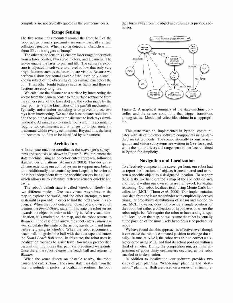
ArchitectureA finite state machine coordinates the scavenger’s subsys-tems and subtasks as shown in Figure 2. We implement thestate machine using an object-oriented approach, followingstandard design patterns (Adamczyk 2003). This design fa-cilitates extending our control system to support new behav-iors. Additionally, our control system keeps the behavior ofthe robot independent from the specific sensors being used,which allows us to substitute different sensors quickly andeasily.
The robot’s default state is called Wander. Wander hastwo different modes. One uses virtual waypoints on themap to explore the world, and the other attempts to travelas straight as possible in order to find the next arrow in a se-quence. When the robot detects an object of a known color,it enters the Found Object state. In this state the robot servostowards the object in order to identify it. After visual iden-tification, it is marked on the map, and the robot returns toWander. In the case of an arrow, the robot enters Follow Ar-row, calculates the angle of the arrow, travels to it, and turnsbefore returning to Wander. When the robot encounters abeach ball, it “grabs” the ball with the duct tape and entersthe Found Beach Ball state. In this state, the robot uses itslocalization routines to assist travel towards a prespecifieddestination. It chooses this path via predefined waypoints.Once there, the robot releases the beach ball and returns toWander.
When the sonar detects an obstacle nearby, the robotpauses and enters Panic. The Panic state uses data from thelaser rangefinder to perform a localization routine. The robot
then turns away from the object and resumes its previous be-havior.
Figure 2: A graphical summary of the state-machine con-troller and the sensor conditions that trigger transitionsamong states. Music and voice files chime in as appropri-ate.
This state machine, implemented in Python, communi-cates with all of the other software components using stan-dard socket protocols. The computationally expensive nav-igation and vision subsystems are written in C++ for speed,while the motor drivers and range-sensor interface remainedin Python for simplicity.
Navigation and LocalizationTo effectively compete in the scavenger hunt, our robot hadto report the locations of objects it encountered and to re-turn a specific object to a designated location. To supportthese tasks, we hand-crafted a map of the competition areaand used it within our own software framework for spatialreasoning. Our robot localizes itself using Monte Carlo Lo-calization (MCL) (Thrun et al. 2000). Our implementationuses data from the laser rangefinder with empirically derivedtriangular probability distributions of sensor and motion er-ror. MCL, however, does not provide a single position forthe robot, but rather a collection of hypotheses of where therobot might be. We require the robot to have a single, spe-cific location on the map, so we assume the robot is actuallyat the position of the most likely hypothesis (the probabilitymode).
We have found that this approach is effective, even thoughit can cause the robot’s estimated position to change drasti-cally. In runs at AAAI, the robot was able to correct a six-meter error using MCL and find its actual position within athird of a meter. During the competition run, a similar ad-justment of about thirty centimeters occurred as the robottraveled to its destination.
In addition to localization, our software provides twokinds of path planning: “wandering” planning and “desti-nation” planning. Both are based on a series of virtual, pre-

specified waypoints placed throughout the map, as shownin Figure 3. For simplicity, we create enough waypoints tohave a line-of-sight from every point on the map to a way-point. Each waypoint stores the heading to two neighboringwaypoints, one for each type of planning.
To wander, the robot asks the navigation software for di-rections to the nearest visible waypoint. The robot then fol-lows this bearing until it is within a predefined distance ofthe next waypoint. Once there, it gets the heading towardsthe next waypoint, and continues this pattern. If the robot en-counters an obstacle along this path, it updates its MCL par-ticle filter. As this might move the robot’s estimated positionby a large amount, the robot requests new instructions to the(possibly changed) nearest waypoint. When the robot en-counters an object, it goes into the Found Object state. Thisresults in object-dependent behavior. For instance, when theobject is an arrow, the robot follows the arrow and returns toWander, ignoring waypoints.
The robot also relies on waypoints to deliver the beachball. Instead of following the “wandering” headings, therobot follows the “destination” headings, traveling as before.In this mode, the robot does not stop to identify other objectsit encounters, though it still localizes itself when it finds anobstacle.
Figure 3: In this map snapshot, the pentagonal robot haswandered from the destination waypoint (the Jerusalemcross at right) towards a second waypoint (the cross at left).When obstacles are detected, a localization update occurs.The red dots represent the particle filter’s pose hypothe-ses with the robot placed at the most likely. Observed ob-jects, e.g., the empty circle representing the beach ball, aremapped relative to the current maximum-likelihood pose.
Visual Object RecognitionWe use an exclusively vision-based system for identifyingscavenger hunt objects. One of the robot’s cameras is an-gled downwards to better view nearby objects on the floor.To recognize a particular item, our software applies the se-quence of image-processing routines detailed in Figure 5.
Each color of interest is defined by thresholds in bothRGB and HSV space. For convenience, our software allowsthe user to change these thresholds in real time by selecting
Figure 4: A raw image and the results of segmentation, con-nected components, and shape processing: best-fit ellipsessurround both the arrow and the yellow bag.
a region in the video window. These color definitions canbe read from and saved to a file. This interface made quickwork of the frequent and important task of calibrating fordifferent lighting conditions.
After the image is segmented with these color definitions,a connected-components routine extracts the largest contigu-ous region of the most abundant color and passes it to severalshape filters.
Shape analysis consists first of PCA-based (i.e.,coordinate-free) ellipse-fitting (Jolliffe 1986), which esti-mates the major and minor diameters and orientation of theregion as shown in Figure 4. Using these statistics and thearea (raw pixel count) of the component, the program cal-culates the object’s roundness (Russ 1998) as the ratio of itsarea to that of a circle of the same diameter:
Roundness =4 ·Area
π · (Max Diameter)2
For simplicity, we assume that the maximum diameter ofan object is the diameter of the major axis of the associated
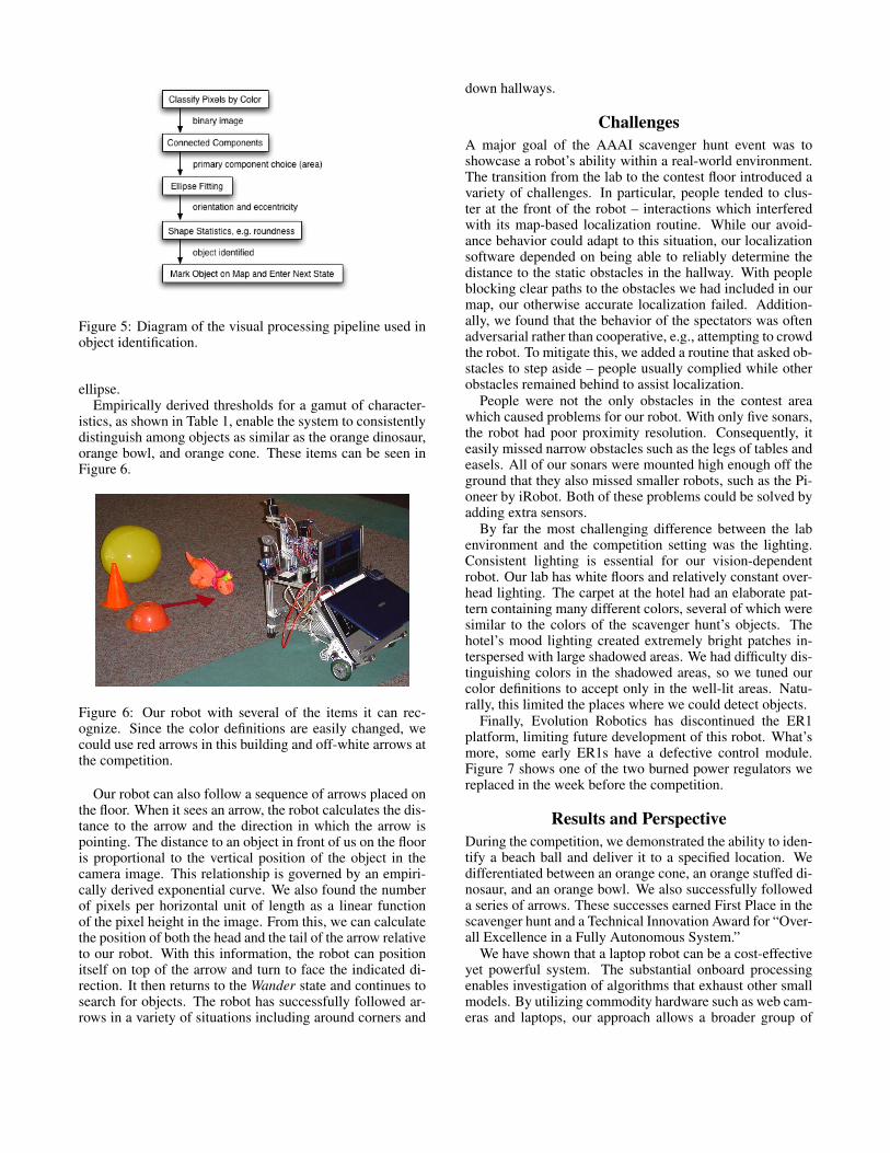
Figure 5: Diagram of the visual processing pipeline used inobject identification.
ellipse.Empirically derived thresholds for a gamut of character-
istics, as shown in Table 1, enable the system to consistentlydistinguish among objects as similar as the orange dinosaur,orange bowl, and orange cone. These items can be seen inFigure 6.
Figure 6: Our robot with several of the items it can rec-ognize. Since the color definitions are easily changed, wecould use red arrows in this building and off-white arrows atthe competition.
Our robot can also follow a sequence of arrows placed onthe floor. When it sees an arrow, the robot calculates the dis-tance to the arrow and the direction in which the arrow ispointing. The distance to an object in front of us on the flooris proportional to the vertical position of the object in thecamera image. This relationship is governed by an empiri-cally derived exponential curve. We also found the numberof pixels per horizontal unit of length as a linear functionof the pixel height in the image. From this, we can calculatethe position of both the head and the tail of the arrow relativeto our robot. With this information, the robot can positionitself on top of the arrow and turn to face the indicated di-rection. It then returns to the Wander state and continues tosearch for objects. The robot has successfully followed ar-rows in a variety of situations including around corners and
down hallways.
ChallengesA major goal of the AAAI scavenger hunt event was toshowcase a robot’s ability within a real-world environment.The transition from the lab to the contest floor introduced avariety of challenges. In particular, people tended to clus-ter at the front of the robot – interactions which interferedwith its map-based localization routine. While our avoid-ance behavior could adapt to this situation, our localizationsoftware depended on being able to reliably determine thedistance to the static obstacles in the hallway. With peopleblocking clear paths to the obstacles we had included in ourmap, our otherwise accurate localization failed. Addition-ally, we found that the behavior of the spectators was oftenadversarial rather than cooperative, e.g., attempting to crowdthe robot. To mitigate this, we added a routine that asked ob-stacles to step aside – people usually complied while otherobstacles remained behind to assist localization.
People were not the only obstacles in the contest areawhich caused problems for our robot. With only five sonars,the robot had poor proximity resolution. Consequently, iteasily missed narrow obstacles such as the legs of tables andeasels. All of our sonars were mounted high enough off theground that they also missed smaller robots, such as the Pi-oneer by iRobot. Both of these problems could be solved byadding extra sensors.
By far the most challenging difference between the labenvironment and the competition setting was the lighting.Consistent lighting is essential for our vision-dependentrobot. Our lab has white floors and relatively constant over-head lighting. The carpet at the hotel had an elaborate pat-tern containing many different colors, several of which weresimilar to the colors of the scavenger hunt’s objects. Thehotel’s mood lighting created extremely bright patches in-terspersed with large shadowed areas. We had difficulty dis-tinguishing colors in the shadowed areas, so we tuned ourcolor definitions to accept only in the well-lit areas. Natu-rally, this limited the places where we could detect objects.
Finally, Evolution Robotics has discontinued the ER1platform, limiting future development of this robot. What’smore, some early ER1s have a defective control module.Figure 7 shows one of the two burned power regulators wereplaced in the week before the competition.
Results and PerspectiveDuring the competition, we demonstrated the ability to iden-tify a beach ball and deliver it to a specified location. Wedifferentiated between an orange cone, an orange stuffed di-nosaur, and an orange bowl. We also successfully followeda series of arrows. These successes earned First Place in thescavenger hunt and a Technical Innovation Award for “Over-all Excellence in a Fully Autonomous System.”
We have shown that a laptop robot can be a cost-effectiveyet powerful system. The substantial onboard processingenables investigation of algorithms that exhaust other smallmodels. By utilizing commodity hardware such as web cam-eras and laptops, our approach allows a broader group of

Object Red Green Blue Hue Saturation Value Additional ConstraintsArrow 91 – 127 32 – 57 0 – 22 0.25 – 0.52 0.79 – 1.00 0.36 – 0.50 0.1 ≤ Roundness (R) ≤ 0.5Beach Ball 148 – 253 1 – 94 0 – 72 0.01 – 0.23 0.69 – 1.00 0.56 – 0.99 Pixel Count ≥ 2500Bowl 98 – 183 97 – 182 0 – 4 -0.66 – 1.00 0.98 – 1.00 0.38 – 0.72 |Angle| < 72◦ and R ≥ 0.35Cone 98 – 183 97 – 182 0 – 4 -0.66 – 1.00 0.98 – 1.00 0.38 – 0.72 |Angle| ≥ 72◦Dinosaur 98 – 183 97 – 182 0 – 4 -0.66 – 1.00 0.98 – 1.00 0.38 – 0.72 |Angle| < 72◦ and R < 0.35
Table 1: Several of the visual characteristics and their admissible ranges used by the vision system to identify scavenger huntobjects. The color values listed are those from the conference, though they change significantly based on lighting conditions.These values are for off-white arrows, yellow beach balls, and orange bowls, cones, and dinosaurs. Note that the bowl, cone,and dinosaur all use the same color definition, and are distinguished solely by shape.
Figure 7: One of the power regulators within EvolutionRobotics’ early Robot Control Modules looking a bit worsefor wear. . .
educators and enthusiasts to explore the field of robotics.
Future WorkFuture work at Harvey Mudd College will focus on improv-ing robots’ spatial-reasoning algorithms by incorporating vi-sion. In particular, there is ongoing research in three dimen-sional mapping (Wnuk, Dang, & Dodds 2004), using vi-sual data to extend the capabilities of MCL, and improvingodometry using an optical flow approach (Campbell, Suk-thankar, & Nourbakhsh 2004).
For additional resources including the scav-enger hunt robot’s source code, please visithttp://www.cs.hmc.edu/∼dodds/AAAIsh.
ReferencesAdamczyk, P. 2003. The anthology of the finite state ma-chine design patterns. In Proceedings of the Pattern Lan-guages of Programs Conference (PLoP).Campbell, J.; Sukthankar, R.; and Nourbakhsh, I. 2004.Visual odometry using commodity optical flow. Proceed-ings of the American Association of Artificial Intelligence(AAAI).Evolution Robotics. 2002. http://www.evolution.com.Horn, B. K. P., and Schunck, B. G. 1992. Determiningoptical flow. Shape Recovery 389–407.
Intel Corporation. 2000. Open Source Computer VisionLibrary: Reference Manual.Jolliffe, I. T. 1986. Principal Component Analysis.Springer.Lucas, B. D., and Kanade, T. 1981. An iterative imageregistration technique with an application to stereo vision.In Proceedings of the 7th International Joint Conferenceon Artificial Intelligence (IJCAI ’81), 674–679.Performance Motion Devices, Inc. 2002. Pilot Motion Pro-cessor: Programmer’s Reference.Russ, J. C. 1998. The Image Processing Handbook. CRCPress, Boca Raton, FL.Shi, J., and Tomasi, C. 1994. Good features to track. InIEEE Conference on Computer Vision and Pattern Recog-nition (CVPR’94).Thrun, S.; Fox, D.; Burgard, W.; and Dellaert, F. 2000. Ro-bust monte carlo localization for mobile robots. ArtificialIntelligence 128(1-2):99–141.Wnuk, K.; Dang, F.; and Dodds, Z. 2004. Dense 3d map-ping with monocular vision. In Proceedings of the 2nd In-ternational Conference on Autonomous Robots and Agents(ICARA ’04).Yau Lam Yiu. 2004. http://www.cs.ust.hk/∼yiu.