scada system for remote control and monitoring of grid
TRANSCRIPT
SCADA System for Remote Control and Monitoringof Grid Connected Inverters
by
c© Sarinda Lahiru Jayasinghe
A thesis submitted to the School of Gradate Stud-ies in partial fulfillment of the requirements for thedegree of Master of Engineering.
Faculty of Engineering and Applied Science
Memorial University of Newfoundland
May, 2018
St. John’s, Newfoundland and Labrador, Canada
Abstract
This thesis presents a development of a supervisory control and data acquisition(SCADA) system for remote control and monitoring of grid-connected inverters. Sincethe number of battery energy storages connected to the grid is increasing the numberof inverters connected to the power system is also rapidly growing. Utilities needto have the ability to monitor and control those inverters connected to the grid tomaintain the stability of the network, to improve the quality of the power suppliedand to stabilize the energy prices. After recognizing the requirement for a low-costSCADA system for grid-tied inverters, essential features that needs to be embeddedin the system have been identified by analyzing SCADA systems in the Wind EnergyInstitute Canada (WEICAN). Based on available options to fulfill the requirementselected SCADA systems were tested during the research. Based on the test resultsan Internet of Things (IoT) based server has been kept as the core of the developedSCADA system, and a SCADA development has been carried out to improve thesystem to deliver features identified. A requirement was recognized to embed an au-tomatic control algorithm to the SCADA system for optimal control of the inverterto maximize the economic benefits out of it by considering the energy price variationand the renewable energy variation through a specific period. Results illustrate thatthe developed SCADA system has been able to deliver features identified during theresearch and the wind prediction algorithm has been able to maximize the economicbenefits.
ii
Table of Contents
Title page i
Abstract ii
Table of Contents iii
List of Tables vii
List of Figures viii
List of Symbols x
List of Abbreviations xi
1 Introduction and Literature Survey 11.1 Background . . . . . . . . . . . . . . . . . . . . . . . . . . . . . . . . . 4
1.1.1 Low-cost SCADA system . . . . . . . . . . . . . . . . . . . . . . 51.1.2 IoT based SCADA systems . . . . . . . . . . . . . . . . . . . . . 81.1.3 Security of SCADA systems . . . . . . . . . . . . . . . . . . . . 101.1.4 Operation scheduling for Battery energy storage . . . . . . . . . 11
1.2 Problem statement . . . . . . . . . . . . . . . . . . . . . . . . . . . . . 131.2.1 Problem I: Features of a SCADA for an energy storage (ES) . . 131.2.2 Problem II: High Cost of SCADA . . . . . . . . . . . . . . . . . 151.2.3 Problem III: Monitoring of an energy storage . . . . . . . . . . . 151.2.4 Problem IV: Controlling of an energy storage . . . . . . . . . . 15
1.3 Objectives and Expected Contributions . . . . . . . . . . . . . . . . . . 151.4 Thesis Overview . . . . . . . . . . . . . . . . . . . . . . . . . . . . . . . 17
1.4.1 Chapter 1: . . . . . . . . . . . . . . . . . . . . . . . . . . . . . . 17
iii
1.4.2 Chapter 2 . . . . . . . . . . . . . . . . . . . . . . . . . . . . . . 171.4.3 Chapter 3 . . . . . . . . . . . . . . . . . . . . . . . . . . . . . . 171.4.4 Chapter 4 . . . . . . . . . . . . . . . . . . . . . . . . . . . . . . 181.4.5 Chapter 5 . . . . . . . . . . . . . . . . . . . . . . . . . . . . . . 181.4.6 Chapter 6 . . . . . . . . . . . . . . . . . . . . . . . . . . . . . . 18
2 SCADA systems used at Wind Energy Institute of Canada: appli-cation, issues, cost and limitations 192.1 Introduction . . . . . . . . . . . . . . . . . . . . . . . . . . . . . . . . . 20
2.1.1 Introduction to SCADA systems used in WEICAN . . . . . . . 202.2 Features of SCADA systems . . . . . . . . . . . . . . . . . . . . . . . . 24
2.2.1 Graphical User Interfaces (GUI) . . . . . . . . . . . . . . . . . . 242.2.2 Alarming . . . . . . . . . . . . . . . . . . . . . . . . . . . . . . 242.2.3 Reporting . . . . . . . . . . . . . . . . . . . . . . . . . . . . . . 27
2.3 Data Logging / Data Redundancy . . . . . . . . . . . . . . . . . . . . . 272.3.1 Data Operations . . . . . . . . . . . . . . . . . . . . . . . . . . 282.3.2 Networking/ Protocols . . . . . . . . . . . . . . . . . . . . . . . 28
2.4 Costs Associated with SCADA . . . . . . . . . . . . . . . . . . . . . . . 302.5 Controlling . . . . . . . . . . . . . . . . . . . . . . . . . . . . . . . . . 302.6 Security . . . . . . . . . . . . . . . . . . . . . . . . . . . . . . . . . . . 302.7 Issues with existing SCADA . . . . . . . . . . . . . . . . . . . . . . . . 302.8 Conclusion . . . . . . . . . . . . . . . . . . . . . . . . . . . . . . . . . . 31
3 IoT Hardware-Based Low Resource and Limited Storage SCADASystems 333.1 Introduction . . . . . . . . . . . . . . . . . . . . . . . . . . . . . . . . . 333.2 Background . . . . . . . . . . . . . . . . . . . . . . . . . . . . . . . . . 343.3 Low Cost Client Side Options . . . . . . . . . . . . . . . . . . . . . . . 35
3.3.1 12E based client . . . . . . . . . . . . . . . . . . . . . . . . . . . 353.3.2 Arduino and Wi-Fi shield based client . . . . . . . . . . . . . . 373.3.3 Raspberry Pi based client . . . . . . . . . . . . . . . . . . . . . 37
3.4 SCADA Server Options . . . . . . . . . . . . . . . . . . . . . . . . . . . 373.4.1 RPI server with local data storage . . . . . . . . . . . . . . . . . 393.4.2 Open Source SCADA software . . . . . . . . . . . . . . . . . . . 393.4.3 IoT service provider . . . . . . . . . . . . . . . . . . . . . . . . 40
iv
3.4.4 Private IOT server . . . . . . . . . . . . . . . . . . . . . . . . . 423.5 Comparison . . . . . . . . . . . . . . . . . . . . . . . . . . . . . . . . . 443.6 Conclusion and Future Works . . . . . . . . . . . . . . . . . . . . . . . 47
4 SCADA system Based on Private thingspeak Sever 484.1 Introduction . . . . . . . . . . . . . . . . . . . . . . . . . . . . . . . . . 484.2 Background . . . . . . . . . . . . . . . . . . . . . . . . . . . . . . . . . 50
4.2.1 SCADA systems for Monitoring and Control . . . . . . . . . . . 504.2.2 Low-cost SCADA for controlling of energy storage . . . . . . . . 51
4.3 Methodology . . . . . . . . . . . . . . . . . . . . . . . . . . . . . . . . 514.3.1 Description of the SCADA . . . . . . . . . . . . . . . . . . . . . 51
4.4 Key Features of the Developed SCADA . . . . . . . . . . . . . . . . . . 584.4.1 Monitoring . . . . . . . . . . . . . . . . . . . . . . . . . . . . . 584.4.2 Controlling . . . . . . . . . . . . . . . . . . . . . . . . . . . . . 604.4.3 Reporting and alerting . . . . . . . . . . . . . . . . . . . . . . . 61
4.5 Testing . . . . . . . . . . . . . . . . . . . . . . . . . . . . . . . . . . . . 614.6 Results and Comparison . . . . . . . . . . . . . . . . . . . . . . . . . . 63
4.6.1 Cloud assisted IoT SCADA Vs. Developed SCADA (Securityfeatures) . . . . . . . . . . . . . . . . . . . . . . . . . . . . . . . 64
4.6.2 Commercial SCADA vs. Developed SCADA . . . . . . . . . . . 654.7 Conclusion . . . . . . . . . . . . . . . . . . . . . . . . . . . . . . . . . . 65
5 Control Strategies for Remote Control of a Grid Tie Inverter andIts implementation using Low-Cost SCADA system 685.1 Introduction . . . . . . . . . . . . . . . . . . . . . . . . . . . . . . . . . 685.2 Problem Statement . . . . . . . . . . . . . . . . . . . . . . . . . . . . . 70
5.2.1 Problem formulation . . . . . . . . . . . . . . . . . . . . . . . . 705.3 Methodology . . . . . . . . . . . . . . . . . . . . . . . . . . . . . . . . 755.4 Results and Validation . . . . . . . . . . . . . . . . . . . . . . . . . . . 795.5 Conclusion and future works . . . . . . . . . . . . . . . . . . . . . . . . 84
6 Summary and Recommendations 866.1 Summary . . . . . . . . . . . . . . . . . . . . . . . . . . . . . . . . . . 87
6.1.1 Research Summary Based on Objective 1 . . . . . . . . . . . . . 876.1.2 Research Summary Based on Objective 2 . . . . . . . . . . . . . 876.1.3 Research Summary Based on Objective 3 . . . . . . . . . . . . . 87
v
6.1.4 Research Summary Based on Objective 4 . . . . . . . . . . . . . 886.2 Significant Contributions . . . . . . . . . . . . . . . . . . . . . . . . . . 886.3 Directions for Future Work . . . . . . . . . . . . . . . . . . . . . . . . . 896.4 List of Publications . . . . . . . . . . . . . . . . . . . . . . . . . . . . . 89
Bibliography 91
A Protocol developed in UNB 95
B Appendix B: Code for Inverter SCADA 97
vi
List of Tables
2.1 Costs Associated with SCADA in CAD [30] . . . . . . . . . . . . 30
3.1 Comparison of client side . . . . . . . . . . . . . . . . . . . . . . . . 443.2 Comparison of private IoT servers . . . . . . . . . . . . . . . . . . 453.3 Comparison of Server Side . . . . . . . . . . . . . . . . . . . . . . . 46
4.1 Comparison of Invert SCADA with VTscada . . . . . . . . . . . 66
5.1 Input data for the algorithm . . . . . . . . . . . . . . . . . . . . . 825.2 Input data for the algorithm . . . . . . . . . . . . . . . . . . . . . 83
vii
List of Figures
1.1 Overview of a SCADA . . . . . . . . . . . . . . . . . . . . . . . . . . . 141.2 Overview of the proposed system . . . . . . . . . . . . . . . . . . . . . 16
2.1 Single Line Diagram for the Wind park [29] . . . . . . . . . . . . . . . 212.2 Data Topology [30] . . . . . . . . . . . . . . . . . . . . . . . . . . . . . 222.3 Control and Monitoring of the Wind Farm . . . . . . . . . . . . . . . . 222.4 VTScada Interface . . . . . . . . . . . . . . . . . . . . . . . . . . . . . 252.5 PureWave Storage Management System interface . . . . . . . . . . . . 252.6 Moventas drive train condition monitoring web interface . . . . . . . . 262.7 Implementation of reports . . . . . . . . . . . . . . . . . . . . . . . . . 27
3.1 Client Side . . . . . . . . . . . . . . . . . . . . . . . . . . . . . . . . . . 363.2 Server Side . . . . . . . . . . . . . . . . . . . . . . . . . . . . . . . . . 383.3 Remote desktop with local data storage . . . . . . . . . . . . . . . . . . 393.4 Data flow diagram for UBIDOTs based approach . . . . . . . . . . . . 413.5 Block diagram for private Blynk server . . . . . . . . . . . . . . . . . . 433.6 Block diagram for private thingspeak serverr . . . . . . . . . . . . . . 44
4.1 Scope of the SCADA . . . . . . . . . . . . . . . . . . . . . . . . . . . . 524.2 Block diagram for the Inverter SCADA . . . . . . . . . . . . . . . . . . 534.3 Block diagram for python script . . . . . . . . . . . . . . . . . . . . . . 564.4 GUI for the Inverter SCADA developed in python . . . . . . . . . . . . 574.5 Thingspeak interface . . . . . . . . . . . . . . . . . . . . . . . . . . . . 594.6 Inverter Developed by the UNB . . . . . . . . . . . . . . . . . . . . . . 624.7 Testing the SCADA with the Inverter . . . . . . . . . . . . . . . . . . . 63
5.1 Model considered with wind turbines and an energy storage . . . . . . 715.2 Proposed architecture . . . . . . . . . . . . . . . . . . . . . . . . . . . . 75
viii
5.3 Block diagram for the algorithm . . . . . . . . . . . . . . . . . . . . . . 765.4 Price graph (CAD) . . . . . . . . . . . . . . . . . . . . . . . . . . . . . 805.5 Wind speed graph (ms−1) . . . . . . . . . . . . . . . . . . . . . . . . . 805.6 Wind power generated graph (kW) . . . . . . . . . . . . . . . . . . . . 805.7 Actual power at common coupling point graph (kW) . . . . . . . . . . 815.8 Optimum power output (Pt) generated by the algorithm (kW) . . . . . 815.9 Operating schedule generated by the algorithm . . . . . . . . . . . . . . 815.10 Optimum power flow to the BESS . . . . . . . . . . . . . . . . . . . . . 82
ix
List of Symbols
Bt Electricity selling or purchasing price at time “t”Pt Power at Common coupling point at time “t”Pwt Wind power generation for time “t”Pdis Discharging power of BESS at time “t”Pch Charging power of BESS at time “t”
Ploads Loads on the system at time “t”PEt Net power delivered to the BESS at time “t”LBp Lower bound for power Pt
UBp Upper bound for power Pt
LBEP Lower bound for power PET
UBEP Upper bound for power PET
Pcutoff Cutoff power for the wind turbinePrated Rated power for the wind turbine
Et Energy at time “t”LBE Lower bound for EnergyUPE Upper bound for EnergyηES
Round cycle efficiency for the BESSηe Self discharging efficiency
PF Power factorPr Real Power
Papp Apparent power∆t Time difference between two iterations
x
List of Abbreviations
SCADA Supervisory Control and Data AcquisitionES Energy Storage
BESS Battery Energy Storage SystemWEICAN Wind Energy Institute Canada
RPI Raspberry PiIoT Internet of ThingsGUI Graphical User InterfaceDC Direct Current
GSM Global System for Mobile communicationRTC Real Time ClockLCD Liquid Crystal DisplayPIC Peripheral Interface ControllerAT ATtention command set
RTU Remote Terminal UnitPLC Programmable Logic Controller
GPRS General Packet Radio ServicePV Photovoltaic
AVR Alf and Vegard’s RISC processorIC Integrated-Circuit
EEPROM Electrically Erasable Programmable Read-Only MemoryDAQ Data Acquisition
WSAN Wireless Sensor and Actuator NetworksCI Critical Infrastructure
WoPeD Workflow Petri Net DesignerMTU Master Terminal UnitGA Genetic AlgorithmEP Evolutionary Programming
PSO Particle Swarm OptimizationNSERC Natural Sciences and Engineering Research Council
GUI Graphical User InterfaceHMI Human Machine Interface
UART Universal Asynchronous Receiver-Transmitter
xi
Chapter 1
Introduction and Literature Survey
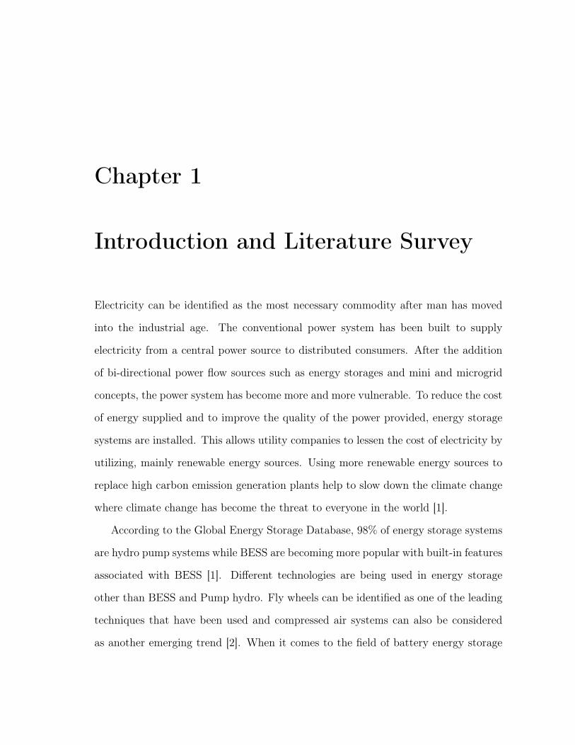
Electricity can be identified as the most necessary commodity after man has moved
into the industrial age. The conventional power system has been built to supply
electricity from a central power source to distributed consumers. After the addition
of bi-directional power flow sources such as energy storages and mini and microgrid
concepts, the power system has become more and more vulnerable. To reduce the cost
of energy supplied and to improve the quality of the power provided, energy storage
systems are installed. This allows utility companies to lessen the cost of electricity by
utilizing, mainly renewable energy sources. Using more renewable energy sources to
replace high carbon emission generation plants help to slow down the climate change
where climate change has become the threat to everyone in the world [1].
According to the Global Energy Storage Database, 98% of energy storage systems
are hydro pump systems while BESS are becoming more popular with built-in features
associated with BESS [1]. Different technologies are being used in energy storage
other than BESS and Pump hydro. Fly wheels can be identified as one of the leading
techniques that have been used and compressed air systems can also be considered
as another emerging trend [2]. When it comes to the field of battery energy storage
2
systems (BESS), developmental work which is carried out to use decentralized BESS
in households as well as near to each distribution transformers [2]. And it is essential
to develop appropriate power converters especially made to be used with BESS and
other energy storages.
There are many advantages of integrating energy storage devices to the power
systems. Not only it enables to reduce carbon emission, but also it will improve the
quality of the electricity supplied by enhancing the reliability of the power supplied
[2]. It will also reduce the cost of the energy supplied by peak shaving and optimizing
the power generation. Those are some of the advantages which users will be benefited
by integrating energy storage systems into the power system. From the utility side,
energy storage has been recognized as the second technology with the most significant
potential as a future revenue source for utilities [2].
There are many barriers when integrating energy storage into the existing power
system. This includes the sizing of the energy storage, how to select the optimum size
of the energy storage, where to install the energy storage, how to operate the energy
storage to maximize the profit are few barriers out of them [2].
The interoperability of energy storage with other elements in the smart grid is an-
other challenge [2]. Specifically, when integrating different technologies to the existing
grid, there will be problems with protocols, hardware mismatches, etc. Many issues
need to be solved before integrating energy storage systems to the current network.
Most importantly just adding an energy storage into the system would not add any
benefit to the system and it has to be optimally controlled to get the maximum ben-
efit out of it. Since the workforce is not cheap energy storage must be monitored and
controlled remotely [2].
In most of the cases, power converters are being utilized to integrate energy storage
systems in the power system, and here inverters are used to inject inverted DC power
3
to the grid. DC power generated by Solar, Wind or any other renewable source of
energy or stored in a battery or any other energy storage device will be fed into the
grid. In present day scenario power injected by small-scale power producers are not
controlled or monitored by the utility, but it will become a requirement for the utility
when the capacity exceeds the stability limits.
Since there is an emerging market for BESS and other energy storage systems
other than pump hydro storage systems required to control and monitoring of power
converters (inverters) will also become a requirement.
There are many types of power converters (inverters) that can be found in the
market while high-end high-cost inverters are coming with embedded SCADA systems
and low-cost with the same efficiency inverters might not come with such sophisticated
features [3]. Usually, most of the expensive inverters like SMA provide embedded
SCADA systems. But most of the lower end inverters and small inverters do not offer
SCADA system. Therefore, there is a scarcity of open source low-cost SCADA for
inverters. For example, SMA sunny boy 10kW inverter costs around CAD 4000.00 [4]
and the maximum efficiency is 98% and a low-cost inverter can be found from Alibaba
at CAD 1000.00 with the same efficiency [5].
After identification of critical features of a SCADA, this research is being con-
ducted to identify the best available open source system so that it is available to be
used under an open source license with the lowest cost that can be used for remote
monitoring and control. Ultimately, to develop a SCADA system for monitoring and
control of a grid-connected inverter.
Many technologies are being utilized to satisfy the above purpose such as Labview
based systems, Simulink based systems, open source software based systems and dedi-
cated SCADA software [3]. But there are many disadvantages attached to each system
which is discussed in the later parts of this chapter. Therefore in this research, the
4
state-of-art technology, Internet of Things (IoT) based architecture has been selected
to develop the SCADA. Following problems are addressed in the thesis,
• Scarcity of user-friendly and secure SCADA systems that can easily integrate
with inverters.
• Optimum controlling of a battery energy storage.
1.1 Background
SCADA is not a novel field. Before the transistor comes into the picture, old telephone
wire based systems were emerging in the field of SCADA system. By the end of the
1950s, Westinghouse and North Electric Company developed the first SCADA called
Visicode [3]. Then it gradually developed after the invention of the transistor which
led to high power computers, minicomputers, microprocessors, etc. A SCADA has
three main parts, Master Terminal Unit (MTU), Remote Terminal Units (RTUs) and
Human Machine Interface (HMI).
Many SCADA systems are developed in the world for monitoring and controlling
purposes. Although this topic covers a vast area, in this literature survey, low cost and
open source options are mainly discussed. There are four primary objectives of this
literature survey. The first is to review low-cost conventional SCADA technologies.
Secondly, to evaluate IoT based technologies. Security of SCADA assessed systems
as the third objective, and finally, to control the battery bank, optimum operating
scheduling methods are being reviewed.
A. M. Gurilo et al. [6] present a SCADA for a wireless sensor and actuator net-
works for monitoring of critical infrastructure in a cost-effective way with eliminating
problems associated with typical SCADA. Problems that happen due to the lack of
deployment flexibility of the sensors that feed it with monitoring data . Authors
5
have given a solution using a gateway and a web services approach for a web-based
SCADA which can be accessed through the Internet. They have also presented a real
scenario using an open source SCADA called MANGO physically applying to monitor
an electrical grid. They have identified several characteristics in a SCADA,
• Dynamism: nodes are flexible and mobile, and that has to be easily added and
removed through less wiring.
• Retrofit: addition of new technology or features to older systems
• Ease of installation: sensor should not need a separate energy source.
• Redundancy: reliability is one of the one of the key feature that needs to be
added into SCADA system.
Additionally, they have defined some challenges associated with developing a
SCADA system as,
• Real-time communications
• Management support
• Security
1.1.1 Low-cost SCADA system
Low-cost hardware
PIC microcontroller based system: Y. P. Zhang et al. [7] presents a SCADA
system with low-cost elements such as PIC18F4620 microcontroller, GSM modem,
Ethernet controller, RTC board, digital thermometer and an LCD. In the proposed
solution remote commands and monitoring are enabled by using two solutions: 1)
6
GSM/3G Short Message Service (SMS) / phone calling or 2) the web page hosted by
the PIC microcontroller. AT commands are used to control the GSM modem .
Although PIC microcontrollers are lower in costs, it is much difficult to handle
pic microcontroller compared to an Arduino. And it is also challenging to interface
devices to PIC compared to Arduino.
ESP8266 based system: Design of a remote control plug using ESP8266 module
is presented by Y. P. Zhang et .al. [8] Since the concept behind IoT is to connect
every sensor and actuator to the internet through an IP address, this project can be
treated as a start.
Though remote controlling of a plug is not a new concept, this design can be treated
as a vital solution with an application of ESP8266 and home appliances plugged in
smart plug, as people can control devices anytime anywhere. WIFI module is essential
to the whole IoT services because existing approaches mainly deal with aspects and
issues related to connectivity and communication .
ESP12E can be considered as one of the emerging trends due to the IoT architec-
ture and low-cost nature of ESP8266. However, this paper narrow down the applica-
bility of ESP8266 for a home application where it has a vast span of the application
domain. This device can be used as a server itself as well as a client.
Arduino Based systems A SCADA system to visualize and monitor the status
of a critical infrastructure system has been presented in [9]. This potential has given
rise to the concept of a web-based controlling to allow end users to access and color
recognition is used. The proposed system in this paper is developed using Arduino
microcontroller board.
Although Arduino and web-based systems are much more superior compared to
PIC based systems, novel Arduino plus IoT based systems play much more superior
7
role compared to the web-based system [8].
Low-cost server
Labview and Simulink based implementations S. G. Hegde et. al. [10] intro-
duce a low-cost SCADA which behaves as a Remote Terminal Unit (RTU) and helps
in gathering the data from the PLC . In their approach, they have following steps,
• The remote terminal unit will collect data from a series of PLCs and make a
database of the received data.
• This data is then sent to a server with the help of Zigbee. The necessary factors
are also shared with the help of a Bluetooth module.
• It is done using Labview with including low-cost hardware devices such as the
ZigBee, Bluetooth, GSM/GPRS module and an LCD.
A. Soetedjo et al. [11] present a data acquisition systems which are technologically
advanced to monitor the wind speed, solar irradiation, and PV temperature based on
a low-cost AVR microcontroller. This project is also a one of the example for a
low-cost SCADA system which uses a low-cost PV module other than an expensive
pyranometer. When analyzing used software and hardware,
• The integrated-circuit (IC) temperature sensor LM35 and a cup-type anemome-
ter are used to measure the temperature and the wind speed respectively,
• Labview is used to develop the control algorithm,
• Instead of a desktop computer they have used a microcontroller to store data in
a serial EEPROM,
8
• Modbus is used as the protocol for communication between DAQ and other
devices.
They also present a framework of Intranet-SCADA using LabVIEW based data
acquisition and management. It describes a configuration of RTU to access and trans-
mit real-time data over the Intranet or Internet. Labview based program is developed
to control the water level in a reservoir. In this paper, cost of LabView not being taken
into account. Though it is straightforward to implement Labview based systems are
expensive compared to other low-cost approaches.
Using Open source SCADA software Grilo A. M et. al. [6] present, a web-
based SCADA software called Mango is used. A SCADA system using WSANs to
visualize and monitor the status of a CI system has been presented. Some of the
common challenges existing in these systems: real-time, management and security
are addressed in the paper [6].
The main drawback of using a standard SCADA software is that those only com-
municates using several protocols, and it is difficult to customize the protocol without
a specific training on the system [12].
1.1.2 IoT based SCADA systems
An agent-based distributed SCADA system is presented by B. T. Sergi et al. [13] and it
is a proposal to integrate Public Key Infrastructure (PKI) functionalities, concerning
on distributed features, into Industrial Control Systems (ICS).
To implement several agents are defined such as interface agent, agent controller,
instrument agent, process agent and host agent. Since it has agent-based architecture,
it can also be considered as a multi-agent based SCADA that having a lot of features.
Additionally, they have shown how a Public Key Infrastructure could be built with
9
distributed elements to be used within a distributed control system. Plus, in the
end, the discussion of security threats because of Multi-Agent system for a SCADA
is briefly discussed.
C. Felipe et al. [14] introduce a wireless communication system related sensor
concept that deals with temperature variations during the scaled industrial process.
There is access to these sensors from anywhere since these sensors are used IoT tech-
nology. The PLC executes according to the set points of temperature sensors, and
this PLC can be contact or control via a graphical programming platform using which
sensor data has been collected into a cloud. This system uses a SCADA to monitor
the system. Also, the system communicates by forming of Petri nets which acts ac-
cording to discrete events and the software used to model that communication system
is WoPeD software.
Thingspeak based SCADA
Due to open source nature of the thingspeak server, many research are now being
conducted using the thingspeak server.
In their project work author uses the IoT thingspeak web server which is an open
API service that can be used with sensors to monitor the sensed data at cloud level
and amalgamated [15]. A unique feature of getting the sensed data to the MATLAB
R2016a utilizing a channel ID and read API key that is assigned by services and able
to track data value at particular intervals. This project uses an Arduino UNO board,
ESP8266 Wi-Fi Module that helps to process and transfer the sensed data to the
thingspeak cloud. The main drawback of using thingspeak.com server is that it
only allows user to upload data at very low frequency, where the user can supply data
for each 15 S. But when the same server is installed locally it will enable the user to
upload data at any frequency [15].
10
1.1.3 Security of SCADA systems
Z. Bonnie et al. [16] present the differences between SCADA systems and standard
IT systems and also discussed how to identify the danger engaged with the SCADA
and how to protect SCADA. This paper has presented set of security property goals
as well.
Also, this article describes the way of identifying possible cyber-attacks like cyber-
induced cyber-physical attacks on SCADA and how to measure and safeguard SCADA
system from such attacks by measuring the impact on SCADA. Moreover, this gives
a comparison between SCADA and traditional IT networks. Authors have set several
security goals or features that should be included in a SCADA system,
• Security property goal
– Timeliness - the time-criticality of the control systems
– Availability - equipment within the system should be ready for use when
is needed
– Integrity - data within a SCADA system being genuine and intact without
unauthorized intervention.
– Confidentiality - unauthorized person should not have any access to infor-
mation.
– Graceful Degradation - Isolation of attacked without being spreading.
• Trust model - the underlying physical security is provided. Notably, the SCADA
server or Master Terminal Unit (MTU) is physically secure, i.e., we assume
there is no direct physical tempering on the server where the central control and
estimation algorithms reside [16].
11
• Threat Model - threats to sensor networks and to conventional IT systems are
also threats to SCADA system.
Hasan et al. [17] give an overview of Trust systems used for SCADA system which
includes fire-walling and network intrusion detection functionalities. Also, TRUST
system can monitor incoming and outgoing traffic as well. However, to lowering
both capital and operational costs, only the essential nodes have been connected to
the system, and those nodes are called TRUST nodes. From the point of network
topology, this paper has discussed forming the trust network also has achieved to
build up a method to protect SCADA while connecting a minimal number of nodes.
In that case, to distribute the nodes and to measure the geographical dispersion,
network segmentation approach and the minimum spanning tree (MST) methods has
been used.
1.1.4 Operation scheduling for Battery energy storage
Many types of research have addressed scheduling problem, and considerable effort
has been dedicated.
Conventional approaches
D.K. Maly et al. [18] present a dynamic programming algorithm for the optimal
charge/discharge scheduling of BESS. The algorithm safeguards the minimization of
the electricity bill for a given battery capacity and also reduces stress on the battery
and prolonging battery life. It shows that the optimal charging curve is expressively
different from the curve conventionally published for BESS.
Chin H. Lo et al. [19] show an algorithm combining multi-pass dynamic pro-
gramming (MPDP) with a time-shift technique which has been developed for two
12
purposes: economic dispatch of BESS and finding optimal BESS power and energy
capacities in a power system. A comparison between DYNASTORE and modified
MPDP approaches had been made with a reasonable discrepancy.
Mohammad S. H. et al. [20] used Lagrange Relaxation (LR) to address the same
optimization problem. The mathematical model discussed is based on the load curve
of a typical power utility shows that the introduction of stored energy in the system
reduces the need for an excessive generation to meet peak load demand. Additionally
it shows that the storage operation accomplishes dynamic operating cost savings by
letting the total sparing of a spinning reserve unit when the load variation between
peak and off-peak levels is less than 25 percent.
AI-based approach
Recently AI-based algorithms such as Genetic Algorithm (GA), Evolutionary pro-
gramming (EA), and Particle Swarm Optimization (PSO) have been used to address
the problem.
Thai D. H. C. et al. [21] use Evolutionary Programming (EP) to minimize the cost
of operating a power system with multiple distributed energy storage resources. The
evolutionary technique syndicates the advantages of both dynamic and evolutionary
programming by evolving piecewise linear convex cost-to-go functions (i.e., the storage
content value curves). Evolutionary programming is shown to be suitable for both
decentralized computing and market applications. Case studies demonstrate that the
technique is robust and efficient for this type of scheduling problem.
Lance C. C. F. et al. [22] suggest a fuzzy and genetic algorithm combined approach.
Two algorithms have been developed. One was based on a Pure Genetic Algorithm
(PGA) approach, and the other was based on a combined Fuzzy-logic and Genetic
Algorithm (FGA) approach. Regarding efficiency and charge-discharge cycles, the
13
FGA method is capable of providing improved results.
Tsung-Ying L. et al. [23] suggest a particle swarm optimization (PSO) based
approach. The new algorithm is named as multipass iteration particle swarm opti-
mization (MIPSO) while preparing the algorithm the effects of wind speed uncertainty
and load are considered.
1.2 Problem statement
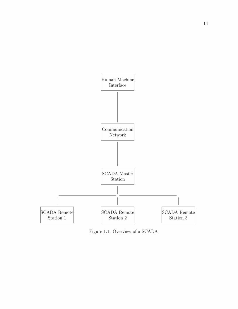
Supervisory controlling and data acquisition, is vital for any devices connected with
a power system. There is an increasing demand for low-cost SCADA systems in
the field of smart grids. Figure 1.1 illustrates a typical arrangement of a SCADA;
it contains few remote stations which connected to a master station, and human-
machine interfacing is done through a communication network, typically through the
Internet.
1.2.1 Problem I: Features of a SCADA for an energy storage
(ES)
Although a broader dedication is put toward SCADA systems by the research com-
munity, features expected from a SCADA system are different from system to system.
Although energy storage is not a new field, requirement of monitoring and control
of ES is not necessary till it contributes a significant amount to the supply and de-
mand of power. Therefore there is a requirement to recognize and document expected
features from a SCADA uses for monitoring and control of an ES.
14
Human MachineInterface
CommunicationNetwork
SCADA MasterStation
SCADA RemoteStation 1
SCADA RemoteStation 2
SCADA RemoteStation 3
Figure 1.1: Overview of a SCADA
15
1.2.2 Problem II: High Cost of SCADA
There are some low cost, open source SCADA systems available. There is a require-
ment to conduct a study to identify suitability of those systems for monitoring and
control of ES.
1.2.3 Problem III: Monitoring of an energy storage
Energy storage systems are essentially be monitored to identify the power flow through
the ES as well as for maintenance purposes. Therefore, based on the adapted system,
SCADA needs to be developed with following features for the inverter developed at
the University of New Brunswick [24],
• Communicate using protocol described in the Appendix A
• Upload data in each second
• Low cost with an upper limit of CAD 500.00.
1.2.4 Problem IV: Controlling of an energy storage
Controlling is an essential feature that needs to be embedded in a SCADA system.
From the literature survey, it can be identified that there is a gap for an optimum con-
trolling of an inverter connected to an energy storage to maximize the profit. Energy
storage works as a load as well a source to the power system, therefore controlling
needs to be done while considering trending price data as well as load data.
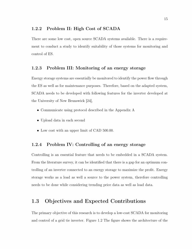
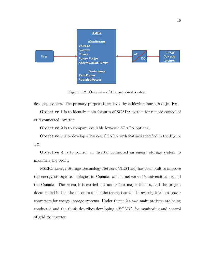
1.3 Objectives and Expected Contributions
The primary objective of this research is to develop a low-cost SCADA for monitoring
and control of a grid tie inverter. Figure 1.2 The figure shows the architecture of the
16
Figure 1.2: Overview of the proposed system
designed system. The primary purpose is achieved by achieving four sub-objectives.
Objective 1 is to identify main features of SCADA system for remote control of
grid-connected inverter.
Objective 2 is to compare available low-cost SCADA options.
Objective 3 is to develop a low cost SCADA with features specified in the Figure
1.2.
Objective 4 is to control an inverter connected an energy storage system to
maximize the profit.
NSERC Energy Storage Technology Network (NESTnet) has been built to improve
the energy storage technologies in Canada, and it networks 15 universities around
the Canada. The research is carried out under four major themes, and the project
documented in this thesis comes under the theme two which investigate about power
converters for energy storage systems. Under theme 2.4 two main projects are being
conducted and the thesis describes developing a SCADA for monitoring and control
of grid tie inverter.
17
1.4 Thesis Overview
1.4.1 Chapter 1:
This chapter mainly gives an overview of the thesis where section 1.4 of the chapter
one gives a brief overview to the research. Section 1.1 gives thorough literature review
and identifies the problem. At the end of the chapter, the author defines objectives
of the research.
1.4.2 Chapter 2
As a part of the research, the author has visited WEICAN to study deferent SCADA
systems. Chapter 2 presents a review on SCADA systems used in WEICAN, their
applications, issues, costs, and limitations.
1.4.3 Chapter 3
This chapter demonstrates a study to compare IoT hardware-based low resource and
limited storage SCADA systems to achieve the objective 2. To achieve this objective
from the client side, an interface between an inverter and the SCADA has been devel-
oped. Three low-cost options are being tested and tabulated the chapter comparing
inherent advantages and disadvantages. For the server side, four different methods are
being tested and compared regarding security, ease of installation, ease of using and
ease of integrating new components. Content presented in this chapter have been pre-
sented at CCECE2017 [12] and part of the work have been presented at NECEC2016
[25].
18
1.4.4 Chapter 4
Chapter 4 presents the development of a low-cost SCADA system to achieve the
objective 3. This chapter describes a development of an IoT based open SCADA for
monitoring and controlling of inverters using an open source thingspeak local server
and Python. The usage of open source software reduces the cost while keeping the
security and the reliability at a higher level [16]. The python based program allows the
user to obtain data from the serial port and posts data on the thingspeak server and
the user is allowed to view and upload data from the server. A graphical user interface
(GUI) has been developed to interact with the SCADA system, and it shows current
data values and allows the user to set the controlling variables. Work demonstrated
in this chapter has been presented in NESTNet [26] conference as a poster.
1.4.5 Chapter 5
Control strategies for remote control of a grid tie converter which connects an en-
ergy storage and the power network are demonstrated in chapter 5. it also shows the
implementation of the suggested control strategy in low-cost SCADA system devel-
oped in chapter 4. Work presented in this chapter has been accepted to present at
NECEC2017 [28].
1.4.6 Chapter 6
Chapter 6 shows the conclusion of the thesis and recommendations for future direc-
tions.

Chapter 2
SCADA systems used at Wind
Energy Institute of Canada:
application, issues, cost and
limitations
This chapter presents a detailed review of SCADA systems used in WEIcan for moni-
toring and controlling of wind turbines as well as battery energy storage and inverter
associated. The primary objective of this chapter is to identify main features of a
typical commercial SCADA system by evaluating SCADA systems used in WEICAN,
Prince Edward Island (PEI). Other than identifying main features, this chapter also
evaluates issues that users faced after using conventional SCADA systems. Other
than features and problems, costs of the system and limitations in different systems
are also documented. While preparing the chapter, the author has visited the Wind
Energy Institute Canada (WEICAN) at the PEI and surveyed for two weeks.
20
2.1 Introduction
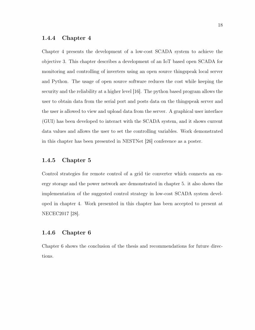
The WEICAN is a non-profitable organization formed in 1981. WEICAN facilitates
researchers to test their wind turbines on their site, and they run standard tests
to check the viability of the design. WEICAN is one of the best places to observe
different types of wind turbines at a single location. Apart from that, the research
institute also own a 10 MW wind park with five 2 MW wind turbines integrated
with a battery energy storage. Figure 2.1 illustrates the single line diagram of the
wind park. Because of their setup and the arrangement, WEICAN can be identified
as the best place to observe different SCADA systems at a single site. WEICAN
uses data acquisition systems to collect data for various wind turbines that they are
testing. Monitoring and the control of the wind park are done using a central SCADA.
For monitoring of the wind turbine blade conditions, monitoring, and control of the
battery energy storage, monitoring of the wind turbine generator condition are done
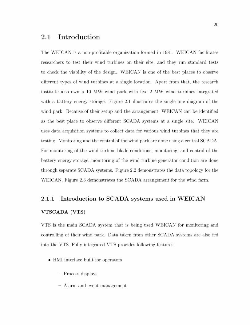
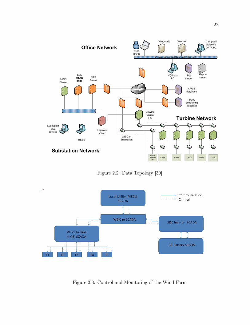
through separate SCADA systems. Figure 2.2 demonstrates the data topology for the
WEICAN. Figure 2.3 demonstrates the SCADA arrangement for the wind farm.
2.1.1 Introduction to SCADA systems used in WEICAN
VTSCADA (VTS)
VTS is the main SCADA system that is being used WEICAN for monitoring and
controlling of their wind park. Data taken from other SCADA systems are also fed
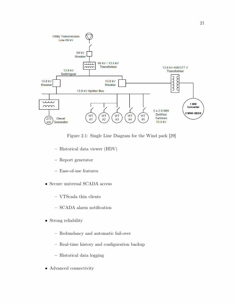
into the VTS. Fully integrated VTS provides following features,
• HMI interface built for operators
– Process displays
– Alarm and event management
21
Figure 2.1: Single Line Diagram for the Wind park [29]
– Historical data viewer (HDV)
– Report generator
– Ease-of-use features
• Secure universal SCADA access
– VTScada thin clients
– SCADA alarm notification
• Strong reliability
– Redundancy and automatic fail-over
– Real-time history and configuration backup
– Historical data logging
• Advanced connectivity
22
INTERNET
DeWind Scada
IPC
CMaS CMaS CMaS CMaS CMaSBlade
conditioning
CMaSdatabase
Blade conditioingdatabase
WEICanSubstation
Kepware server
SEL RTAC 3530
SubstationSEL
devices
BESS
VTS ServerMECL
Server
VQ Data PC
Campbell ScientificDATA PC
Report server
END USER
Windmatic Wesnet
SQL server
Communication (Fiber and Ethernet)
Figure 2.2: Data Topology [30]
Figure 2.3: Control and Monitoring of the Wind Farm
23
– ODBC server
– OPC client / server
– Web services
– Modem management
– Polling management
Engineering Operating System (EOS)
EOS comes with the DeWind wind turbines. In this institute, VTScada provides the
upper-level control capabilities, and the EOS is working the lower level controller. It
is also designed for data acquisition. EOS is coming with following components
• EOS Control: Software, and hardware for the management and control of the
wind energy plants and communication links, as well as for handling local data
backups.
Campbell Scientific
Campbell Scientific has a vast range of products for data logging and SCADA systems.
In the institute they are using these systems for data acquisition process on a wind
turbine that are tested.
ION Data Acquisition
ION meter is an energy meter produced by Schneider Electric, and it keeps data about
power consumption. The user can import data from the meter using ION software.
24
IMC Data acquisition system
This data acquisition system supposes to get data from five turbines, met mast, and
strain gauges. It sends data to the central SCADA system.
CMAS Condition Management System
This system supposes to monitor gearbox condition. It also monitors other drive train
components in a wind turbine.
2.2 Features of SCADA systems
This section demonstrates how HMI is implemented analyzing few of SCADA systems.
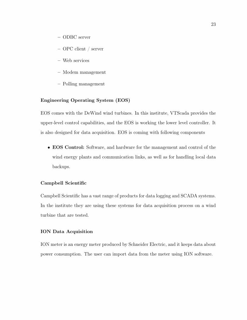
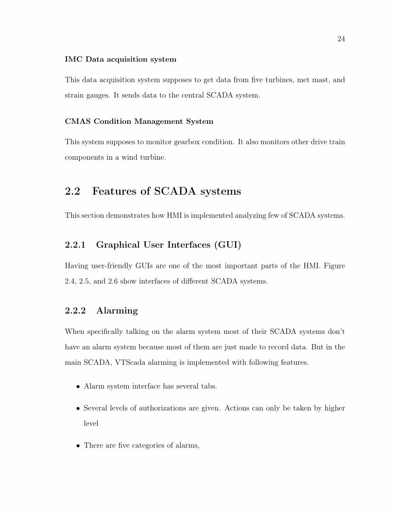
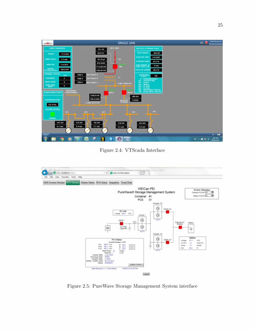
2.2.1 Graphical User Interfaces (GUI)
Having user-friendly GUIs are one of the most important parts of the HMI. Figure
2.4, 2.5, and 2.6 show interfaces of different SCADA systems.
2.2.2 Alarming
When specifically talking on the alarm system most of their SCADA systems don’t
have an alarm system because most of them are just made to record data. But in the
main SCADA, VTScada alarming is implemented with following features.
• Alarm system interface has several tabs.
• Several levels of authorizations are given. Actions can only be taken by higher
level
• There are five categories of alarms,
25
Figure 2.4: VTScada Interface
Figure 2.5: PureWave Storage Management System interface
26
Figure 2.6: Moventas drive train condition monitoring web interface
1. Event
2. Critical
3. High
4. Warning
5. Notice
• In critical and above the system automatically sends a text message or email to
the responsible person. If someone acknowledges an alarm, his or her name will
be recorded in the system.
Implementing an alarm
Alarming events are needed to be entered to the SCADA following steps.
1. Tag (data point) must be created
2. An alarm Tag is made associated to the tag created in the first step
27
Figure 2.7: Implementation of reports
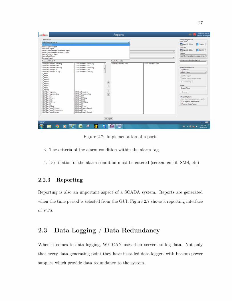
3. The criteria of the alarm condition within the alarm tag
4. Destination of the alarm condition must be entered (screen, email, SMS, etc)
2.2.3 Reporting
Reporting is also an important aspect of a SCADA system. Reports are generated
when the time period is selected from the GUI. Figure 2.7 shows a reporting interface
of VTS.
2.3 Data Logging / Data Redundancy
When it comes to data logging, WEICAN uses their servers to log data. Not only
that every data generating point they have installed data loggers with backup power
supplies which provide data redundancy to the system.
28
All SCADAs are written in such a way that when the network is broken data
logging parts are done in their storage, and it will be communicated to others such
as VTS when the system is fixed. This case is same in the power failure too. For this
kind of a scenario, where the network got failed due to power failures in routers and
other network equipment and data loggers near to data originating points log data
(these apparatus are provided with backup UPS system which can operate for 4- 5
hours).
2.3.1 Data Operations
Most analysis is done using Excel (for example to generate a power curve we developed
a spreadsheet with many macros to create a power curve according to IEC 61400-12-
1 Power Performance Measurements of Electricity Producing Wind Turbines) [30].
They also import data into other software such as Windographer and WindPro to do
analysis and generate reports. Sometimes students/visitors use MATLAB and their
software. On average it can estimate about 1 hour per week will be used for data
transferring from data loggers. About data sampling, representative data sampling is
1 Hz, storage backup is done daily/weekly when the project is active, storage backup
is manually backup every month to external hard drive.
2.3.2 Networking/ Protocols
In WEICAN, they use fiber optic, Ethernet, and WIFI (only in T5 for the blade
conditioning system, between nacelle and hub) for networking.
TCP/IP
• Transmission Control Protocol (TCP) and the Internet Protocol (IP) are net-
working protocols.

29
DNP3
• Distributed Network Protocol (DNP3) utilized between components in process
automation systems. Utilities such as electric and water companies are using
this protocol.
• Uses for communication between wind turbine and the SCADA and also for com-
munication between Maritime Electric Company, Limited (MECL) and SCADA
Modbus
• Modbus is a serial communications protocol [30].
• Communication between battery energy storage system and the SCADA
IMC/Canbus
• (T5 MET mast) Inter-Module Communication (IMC) protocol is a message-
oriented protocol. This protocol is mainly used for real time applications.
EtherCAT
• EtherCAT is a highly Ethernet network protocol.
SEL Fast messaging
• The SEL Fast Messaging protocol allows the SEL-3530 RTAC to communicate
directly to SEL relays and communications processors.
• Uses for communication between substation devices and the SCADA
30
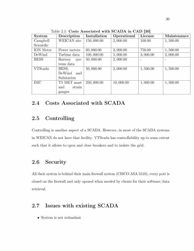
Table 2.1: Costs Associated with SCADA in CAD [30]System Description Installation Operational License MaintenanceCampbellScientific
WEICAN site 150, 000.00 2, 000.00 100.00 1, 500.00
ION Meter Power meters 60, 000.00 2, 000.00 750.00 1, 500.00DeWind Turbine data 100, 000.00 5, 000.00 3, 000.00 2, 000.00BESS Battery sys-
tems data50, 000.00 2, 000.00 - -
VTScada BESS,DeWind andSubstation
50, 000.00 2, 000.00 1, 500.00 1, 500.00
IMC T5 MET mastand straingauges
250, 000.00 10, 000.00 1, 000.00 1, 500.00
2.4 Costs Associated with SCADA
2.5 Controlling
Controlling is another aspect of a SCADA. However, in most of the SCADA systems
in WEICAN do not have that facility. VTScada has controllability up to some extent
such that it allows to open and close breakers and to isolate the grid.
2.6 Security
All their system is behind their main firewall system (CISCO ASA 5510), every port is
closed on the firewall and only opened when needed by clients for their software/data
retrieval.
2.7 Issues with existing SCADA
• System is not redundant
31
• To improve the reliability, they replace computers every three years
• Data backup is manually done
• Each system has vulnerability if it’s main computer crashes and needs to be
replaced. Not having redundancy, but they are very technical and can get a
replacement system very quickly and replace.
2.8 Conclusion
From the analysis of different SCADA systems in WEICAN, following main features
have been identified,
Monitoring
• Allows to monitor system in real time
• Allows the user to view historic data in different intervals
• Allows to generate reports based on past data
• Alarms the user in predefined events
Control
• Let the user to control the device through a GUI
• Automatic controlling is given at possible scenarios
Security Security of the inverter is improved through different approaches,
• Adding different authorization levels
32
• Using a firewall
• Using locally installed servers for all operations
Redundancy: Data redundancy is achieved by two different methods,
• Adding redundant data storages
• Adding data storage near to the remote SCADA stations.
Identification of these features are vital to the rest of the thesis. When selecting a
low-cost SCADA system these features were kept as evaluation criteria. Additionally,
while developing a SCADA system in chapter 4, these features were embedded into
the system.
Chapter 3
IoT Hardware-Based Low Resource
and Limited Storage SCADA Systems
3.1 Introduction
This chapter presents low-cost hardware based, moderate resource and limited storage
SCADA systems that can fulfill the primary objective of the research. This study is
being conducted to identify the best available technology that utilized for remote
monitoring and control of energy storage. A testbed is developed with an inverter
and DC voltage sensor and a DC current sensor with a relay to disconnect from the
DC side. This chapter consists of two main parts. In the first part, available options
for the client side is discussed by the author. In the second part, options for the server
part are documented, and at the end of the chapter, both client and the server parts
are being compared.
34
3.2 Background
From the economical perspective cost of the system can be identified as one of the most
critical factors. As a part of the research, a survey has been carried out in WEICAN
to find out more details about commercially available SCADA systems [30].
In the research institute, VTscada is used for monitoring controlling of wind tur-
bines and battery energy storage system. The initial cost of the system for 1,000 I/O
tag Development Runtime package is about CAD 5,595.00 [32]. For maintenance and
emergency support 20% annual fee is charged for the initial price. In this chapter that
cost is being taken as the baseline. And security can be recognized as one of the most
critical factors to be considered in smart grids. IEC 62351 defines cybersecurity for
communication protocols. However, the security of the developed system is not tested
following this IEC 62351. Instead, going through someone else‘s server and having
open ports or not are considered [31].
In most of the literature, LabVIEW based monitoring and control methods are
being used [33]. M.N. Ashraf et al. [33] presents a framework of Intranet-SCADA us-
ing LabVIEW based data acquisition and management. Additionally, it describes the
configuration of remote terminal units to access and transmit real-time data over the
Intranet or Internet[33]. The main disadvantage of this method is to use LabVIEW,
because of its costs.S. Anam et al. [11] provide a good overview of the evolution
of SCADA technologies along with highlighting the security challenges of critical in-
frastructure (CI), also provides the existing best practices and recommendations for
improving and maintaining security. Additionally, it offers a reasonable explanation
on IoT based SCADA system. A review IoT based monitoring and control systems
have far more superior qualities such as natural maintain and easy to integrate [34].
Connecting the inverter to the SCADA can be recognized as the critical part of this
35
research. There are some ways to connect where in most of the literature for low-cost
SCADA systems PIC based data acquisition systems are used [7]. The main drawback
of PIC based systems is that, unlike Arduino based systems, it is more difficult to
connect to new peripherals.
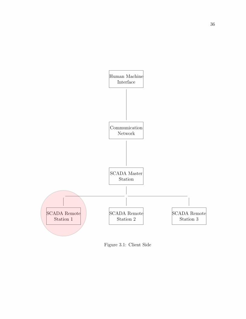
3.3 Low Cost Client Side Options
As shown in the Figure 3.1 in this section, options for remote SCADA stations are
considered. Three main client platforms are used, namely ESP12E DEVKIT V2 based
client, Arduino and Wi-Fi shield based client and Raspberry Pi based client (RPI).
3.3.1 12E based client
ESP-12E is a UART-Wi-Fi module, with very modest prices in the trade and ultra-
low power consumption technology, designed especially for mobile devices and IoT
applications [8]. User’s physical device can be connected to a Wi-Fi wireless network,
Internet or intranet communication with networking capabilities. ESP12E can be
programmed with Arduino IDE. It can directly work as a Server itself or connect to
WiFi and send data to remotely located server with little cost and high processing
speed about 80 MHz (160 MHz maximum) where Arduino Mega has only (16 MHz).
This module has 4 Mb flash memory as well. But there are few drawbacks such as
it has just one Analog input because of that a multiplexer is used to overcome this
issue (SN 74LS151N). The major drawback is its low WiFi range. The total cost of
the client side is CAD 15.00 [35].
36
Human MachineInterface
CommunicationNetwork
SCADA MasterStation
SCADA RemoteStation 1
SCADA RemoteStation 2
SCADA RemoteStation 3
Figure 3.1: Client Side
37
3.3.2 Arduino and Wi-Fi shield based client
In this case, Arduino UNO is used along with an Arduino WiFi shield. All draw-
backs mentioned with the ESP12E are resolved with this. However, system reliability
depends on individual reliabilities as a system the reliability would be lower than indi-
vidual components. Major drawback comparing to ESP12E is the cost of the system
where the Arduino UNO will cost about CAD 40.00 [35] and WIFI shield cost CAD
130.00 [35] where the total cost is about ten times (10X) than ESP12E.
3.3.3 Raspberry Pi based client
Raspberry Pi 3 is also an excellent option which is cheaper and reliable. But the
cost is again fifteen times more than ESP system when we include keyboard, mouse,
monitor, and power. As a part of the project, RPI 2 is tested with WI-FI adapter and
Ethernet where Arduino MEGA is working as the primary analog reader and data
transmitted to the RPI over SPI. In their paper A. D. Deshmukh et al. [36] use RPI
based system for monitoring purpose.
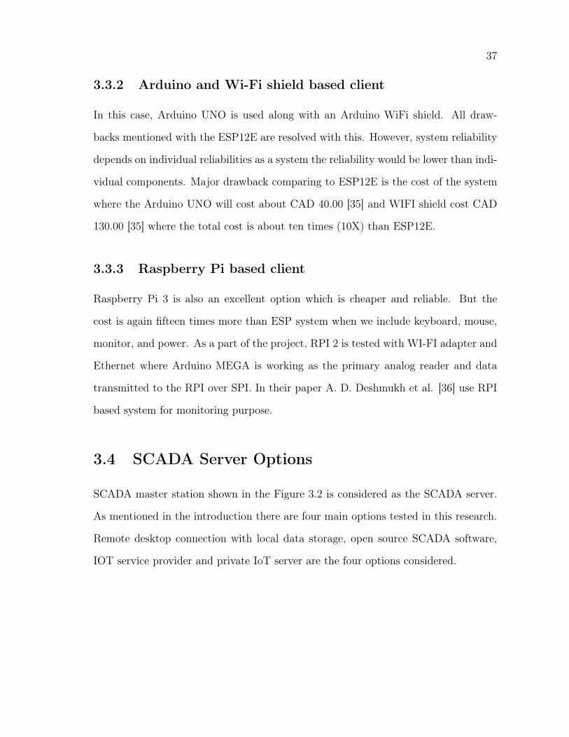
3.4 SCADA Server Options
SCADA master station shown in the Figure 3.2 is considered as the SCADA server.
As mentioned in the introduction there are four main options tested in this research.
Remote desktop connection with local data storage, open source SCADA software,
IOT service provider and private IoT server are the four options considered.
38
Human MachineInterface
CommunicationNetwork
SCADA MasterStation
SCADA RemoteStation 1
SCADA RemoteStation 2
SCADA RemoteStation 3
Figure 3.2: Server Side
39
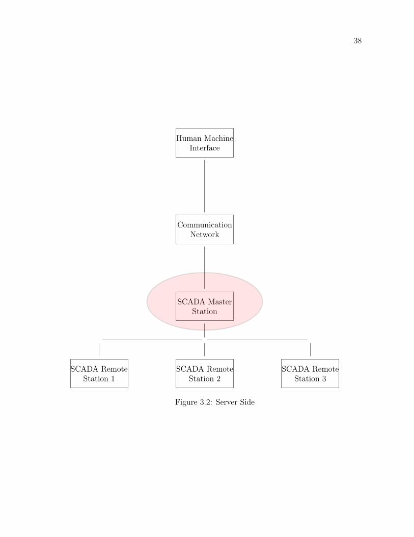
Figure 3.3: Remote desktop with local data storage
3.4.1 RPI server with local data storage
This is the first and the easiest option out of four server-side options that are being
discussed in this section. In this method, remote desktop software like TeamViewer,
VNC, and Chrome Remote desktop has been used to access the client side com-
puter. However, security wise this option treated as the last out of four main options.
Another drawback is that this approach needs high bandwidth for remote desktop
communications. Figure 3.3 shows block diagram for this method.
3.4.2 Open Source SCADA software
Use an existing open source SCADA has been used to develop a suitable SCADA using
it. RapidScada, PV browser, Mango are several examples of open SCADA systems.
M. S. Almas et al. [37] show how to use SCADA BR for monitoring and limitations
such as it takes only two points per second (maximum resolution) when plotting the
data
For this research, Rapid SCADA has been tested. It is good to be used with
standard protocols like Modbus and OPC, but for developmental purposes, it is not

40
flexible. Especially, when it is used with proposed clients like Arduino, ESP12E, and
RPI, it takes more time to implement protocols. Security of this system can be quickly
improved by closing all ports and use inside the intranet. Unlike remote computer-
based system, since data stored inside the intranet, there is no need to open ports in
this method. Therefore, when it comes to security concerns, this option shows highly
secured.
3.4.3 IoT service provider
For last few years, internet connected many often referred as internet of things. In
IoT based SCADA systems with sensors and actuators, communications based on a
separate IP address each connected to a cloud. Most importantly this decentralized
approach allows sensors and actuators to communicate with each other and take their
own decisions and it provides autonomy to devices. When it comes to a broader
picture, IoT also allows centralized data management for larger networks wherein
conventional SCADA systems central data handling is complicated. SCADA systems
which are not capable of communicating together makes the involvement of a lot of hu-
man effort to collect data from one SCADA and feed some of those data to somewhere
else. IoT helps to eliminate this problem entirely where all sensors can feed their data
to the cloud, and the cloud platform does all the calculations like machine learning,
trend calculations, etc. Devices connected to power systems need such sophisticated
SCADA than anything else because of the complexity. Conventional SCADA has
been used for remote controlling and monitoring of an inverter with above-described
drawbacks.
41
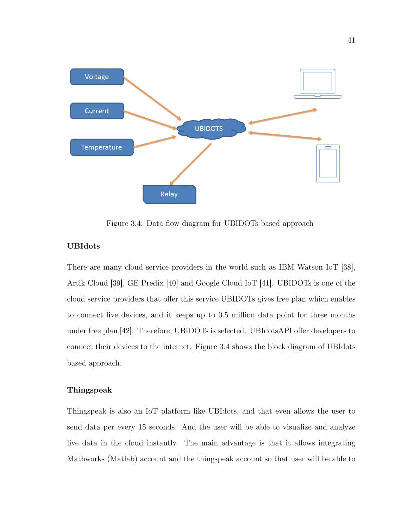
Figure 3.4: Data flow diagram for UBIDOTs based approach
UBIdots
There are many cloud service providers in the world such as IBM Watson IoT [38],
Artik Cloud [39], GE Predix [40] and Google Cloud IoT [41]. UBIDOTs is one of the
cloud service providers that offer this service.UBIDOTs gives free plan which enables
to connect five devices, and it keeps up to 0.5 million data point for three months
under free plan [42]. Therefore, UBIDOTs is selected. UBIdotsAPI offer developers to
connect their devices to the internet. Figure 3.4 shows the block diagram of UBIdots
based approach.
Thingspeak
Thingspeak is also an IoT platform like UBIdots, and that even allows the user to
send data per every 15 seconds. And the user will be able to visualize and analyze
live data in the cloud instantly. The main advantage is that it allows integrating
Mathworks (Matlab) account and the thingspeak account so that user will be able to
42
use features such as machine learning platform from Matlab [43].
Blynk
Blynk is a platform that allows the user to control their Arduino, Raspberry Pi,
ESP12E boards using a mobile phone app. Both Android and iPhone users can use
the Blink app. Implementing this method is easy. However, this is also going through
a third party server. Therefore, data security and privacy will become an issue [44].
3.4.4 Private IOT server
Though it is easy to implement above methods, it will be unsecured to use someone
else‘s IoT cloud or a server. Therefore, in this fourth and final approach, open source
private IoT servers are tested.
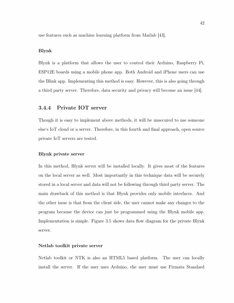
Blynk private server
In this method, Blynk server will be installed locally. It gives most of the features
on the local server as well. Most importantly in this technique data will be securely
stored in a local server and data will not be following through third party server. The
main drawback of this method is that Blynk provides only mobile interfaces. And
the other issue is that from the client side, the user cannot make any changes to the
program because the device can just be programmed using the Blynk mobile app.
Implementation is simple. Figure 3.5 shows data flow diagram for the private Blynk
server.
Netlab toolkit private server
Netlab toolkit or NTK is also an HTML5 based platform. The user can locally
install the server. If the user uses Arduino, the user must use Firmata Standard
43
Figure 3.5: Block diagram for private Blynk server
program. But unlike Blynk, the user can use other pins after allocating data I/O pins
accordingly. The main drawback of this system is that they do not have any method
to store data. The user must use a separate database (that part has not been tested as
a part of the chapter because it is out of the scope). Communication is done through
the serial protocol, and that can be recognized as the other main drawback of this
system.
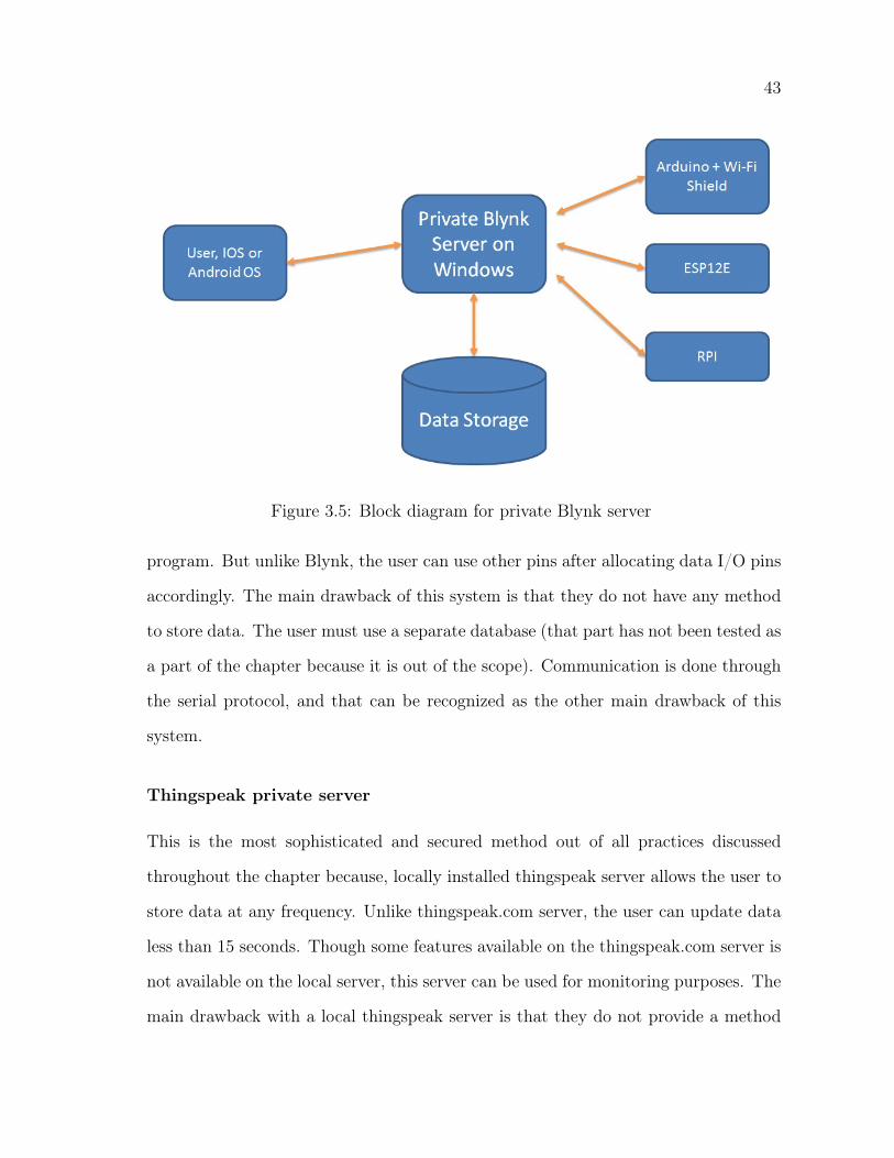
Thingspeak private server
This is the most sophisticated and secured method out of all practices discussed
throughout the chapter because, locally installed thingspeak server allows the user to
store data at any frequency. Unlike thingspeak.com server, the user can update data
less than 15 seconds. Though some features available on the thingspeak.com server is
not available on the local server, this server can be used for monitoring purposes. The
main drawback with a local thingspeak server is that they do not provide a method
44
Figure 3.6: Block diagram for private thingspeak serverr
to control equipment with the local server. The user needs to develop a separate
program to control devices, for example to on/off the inverter. Figure 3.6 shows data
flow diagram for the thingspeak private server based approach.
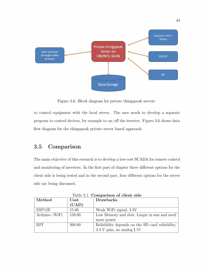
3.5 Comparison
The main objective of this research is to develop a low-cost SCADA for remote control
and monitoring of inverters. In the first part of chapter three different options for the
client side is being tested and in the second part, four different options for the server
side are being discussed.
Table 3.1: Comparison of client sideMethod Cost
(CAD)Drawbacks
ESP12E 15.00 Weak WiFi signal, 3.3VArduino+WiFi 150.00 Low Memory and slow, Larger in size and need
more powerRPI 200.00 Reliability depends on the SD card reliability,
3.3 V pins, no analog I/O
45
client side: From the client side, the main requirement would be to have low-cost
equipment because some equipment will be proportional to number of inverters that
will increase the cost of the client side with the number of inverters in the population.
The reliability of the component is also important. The comparison which has done
based on those two factors shown in the table 3.1.
server side Server-side is crucial for a SCADA system. The main idea of the server
side is to log data and visualize data when requested by an authorized user. Therefore,
the server should be competent enough to store data securely. In addition to that,
the other main objective of the server side is to convey the command sent by the user
to the client.
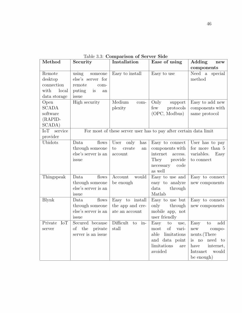
In table 3.3, four available approaches for the server side are being compared and
tabulated concerning security, ease of installation, ease of using and ease of adding
new components. In this case, security will become the primary concern because
sensitive data flows might be flowing. Therefore, going through third party server is
not a good option to be considered.
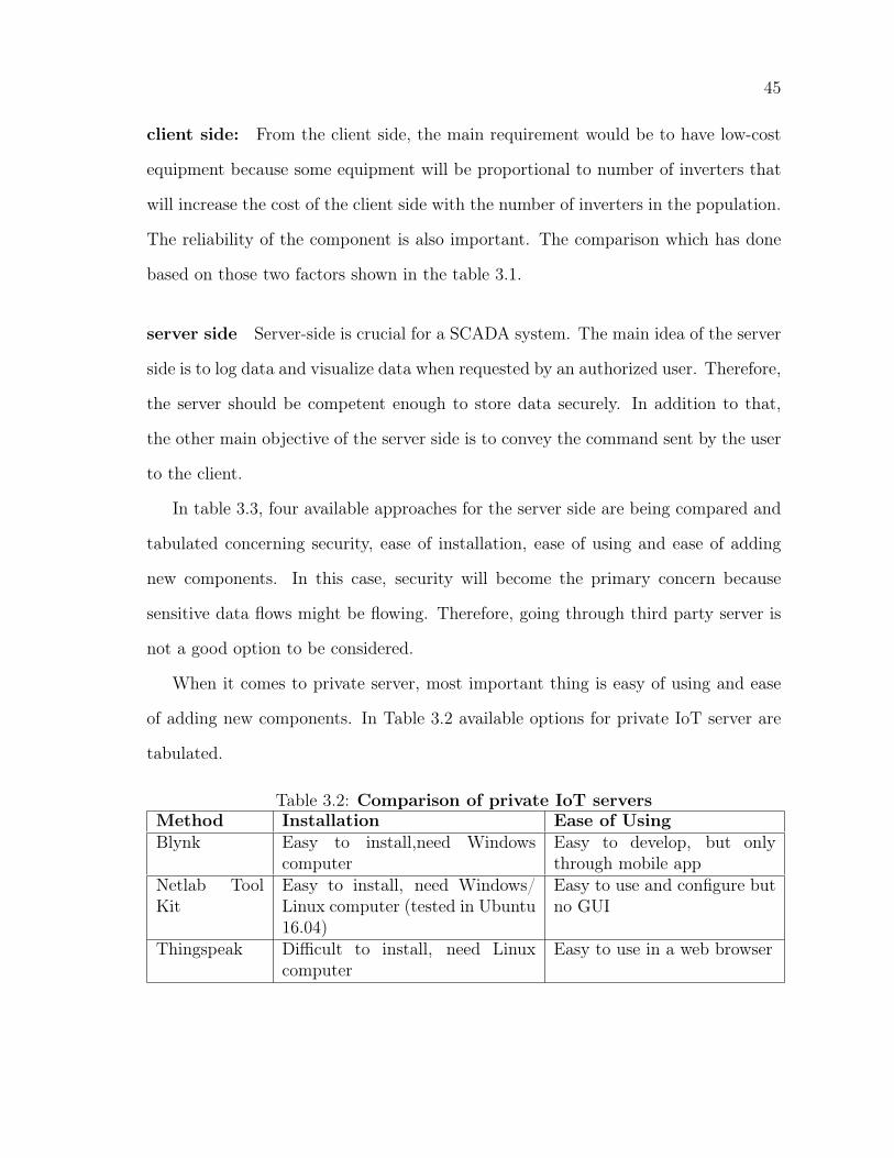
When it comes to private server, most important thing is easy of using and ease
of adding new components. In Table 3.2 available options for private IoT server are
tabulated.
Table 3.2: Comparison of private IoT serversMethod Installation Ease of UsingBlynk Easy to install,need Windows
computerEasy to develop, but onlythrough mobile app
Netlab ToolKit
Easy to install, need Windows/Linux computer (tested in Ubuntu16.04)
Easy to use and configure butno GUI
Thingspeak Difficult to install, need Linuxcomputer
Easy to use in a web browser
46
Table 3.3: Comparison of Server SideMethod Security Installation Ease of using Adding new
componentsRemotedesktopconnectionwith localdata storage
using someoneelse’s server forremote com-puting is anissue
Easy to install Easy to use Need a specialmethod
OpenSCADAsoftware(RAPID-SCADA)
High security Medium com-plexity
Only supportfew protocols(OPC, Modbus)
Easy to add newcomponents withsame protocol
IoT serviceprovider
For most of these server user has to pay after certain data limit
Ubidots Data flowsthrough someoneelse’s server is anissue
User only hasto create anaccount
Easy to connectcomponents withinternet access.They providenecessary codeas well
User has to payfor more than 5variables. Easyto connect
Thingspeak Data flowsthrough someoneelse’s server is anissue
Account wouldbe enough
Easy to use andeasy to analyzedata throughMatlab
Easy to connectnew components
Blynk Data flowsthrough someoneelse’s server is anissue
Easy to installthe app and cre-ate an account
Easy to use butonly throughmobile app, notuser friendly
Easy to connectnew components
Private IoTserver
Secured becauseof the privateserver is an issue
Difficult to in-stall
Easy to use,most of vari-able limitationsand data pointlimitations areavoided
Easy to addnew compo-nents.(Thereis no need tohave internet,Intranet wouldbe enough)
47
3.6 Conclusion and Future Works
There are some options available when developing a SCADA system for an inverter.
The primary objective of this chapter is to find out the best possible method among all
available techniques. Mainly chapter has two parts as client and server. Three main
approaches are being tested for the client side and, advantages and disadvantages of
each system are discussed. Considering all advantages and disadvantages ESP12E
based system can be recognized as the best option for a client which will gather data
and feed into a server. As the next stop, four significant approaches being tested
to identify the best approach. At the end of the chapter, all methods are compared
regarding security, ease of installation, ease of using and ease of integrating new
components. Considering all facts thingspeak based local server has been identified
as the best available option for the server side. Though ESP12E based client and
thingspeak based server are selected, there are some inherent drawbacks attached
with both systems. As future works developments can be carried out to improve
reliability and security plus improve controllability using a thingspeak local server.
Chapter 4
SCADA system Based on Private
thingspeak Sever
4.1 Introduction
The primary objective of this chapter is to demonstrate the development of a low-cost
open source SCADA system with sophisticated features adopted from commercial
SCADA systems for power converters. Work presented in this chapter was presented
at NESTnet annual conference [26].
As a part of the research, a survey has been carried out regarding SCADA software
that is being used in WEICAN to find out more details about commercially available
SCADA systems that can be used for monitoring and control of inverters. In the
research institute, VTscada is used for monitoring controlling of wind turbines and
battery energy storage system. Considering the cost of the system the Initial cost of
the system includes 1,000 I/O tag Development Runtime package is about 5,595.00
CAD. And for maintenance and emergency support 20% [32] of the annual fee is
charged from the initial price. The following features are being offered:
49
• It allows users to log data for monitoring purposes
• Sends email alerts for defined incidents
• Views data in time intervals
• It gives trending data
• Generates reports
• Allows sending control parameters
This chapter discusses IoT based approach to achieve the primary objective of
a conventional SCADA system that is to communicate with sensors and actuators
and with the Internet with a separate IP address when compared to a cloud. This
approach is designed based on IoT architecture as cloud assisted SCADA systems.
Most importantly, the decentralized approach in IoT architecture allows sensors
and actuators to communicate with each other and take their own decisions, and
it provides autonomy to devices. When it comes to the macro picture, IoT also
allows centralized data management for larger networks wherein conventional SCADA
systems central data handling is complicated. In research facilities like WEIcan [30],
they use several SCADA systems which cannot communicate together, and that needs
the involvement of a lot of human effort to collect data from one SCADA and feed
some of those data to somewhere else. IoT helps to eliminate this problem entirely
where all sensors can feed their data to the cloud, and the cloud platform does all
the calculations like machine learning, trend calculations, etc. Or else the thingspeak
server can act as a facilitator for other SCADA system using communication between
each other.

50
4.2 Background
4.2.1 SCADA systems for Monitoring and Control
Security of SCADA systems
Security of a conventional SCADA In the field of security of SCADA systems
B. Zhu et al. [16] present the differences between SCADA systems and standard IT
systems and also discuss how to identify the danger engaged with the SCADA and
how to protect SCADA. To do so, this article presented set of security property goals
as well [16]. Also, this article described a way of identifying possible cyber-attacks like
cyber-induced cyber-physical attacks on SCADA and how to measure and safeguard
SCADA system from such attacks by measuring the impact on SCADA. Moreover,
this gives a comparison between SCADA and traditional IT networks, how the attacks
affect such systems using methods like attack categorization and comparing important
feature and commonalities of such attacks. The Authors have set several security goals
or feature that should be included in a SCADA system,
Security of IoT SCADA systems: In their work on the security of cloud assisted
SCADA systems A. Sajid et al. [45] highlight the security challenges that the indus-
trial SCADA systems face in an IoT-cloud environment, and present attributes to be
taken into consideration in IoT SCADA systems.
• Data integrity and privacy
• Data logging
• Ownership
• Authorization and encryption
51
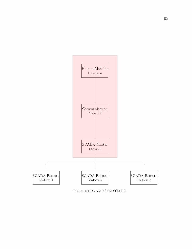
The requirement of a low-cost SCADA system for monitoring and controlling of
power converters is identified as the main problem which is addressed in this chapter.
Based on the results from the chapter 3, there is a requirement to develop a local
cloud assisted SCADA system. Figure 4.1 defines the scope of this chapter.
4.2.2 Low-cost SCADA for controlling of energy storage
DC/AC power converters used in energy storage systems necessarily need to be con-
trolled and monitored. Though there are many SCADA systems available in the
market, the cost of the system has become a barrier. Results from the research which
has been carried out to compare different SCADA systems and low-cost open source
SCADA options available for remote controlling and monitoring of inverters are pub-
lished in CCECE 2017 [12]. As the conclusion of that paper thingspeak based local
server that is being installed in a Ubuntu 16.04 has been identified as the best avail-
able solution for the problem. This chapter describes the developmental work that
has been done to use the server for monitoring and controlling of an inverter while
providing all the features of the commercially available software.
4.3 Methodology
4.3.1 Description of the SCADA
As illustrated in Figure 4.2, the server is installed in a X86 computer with Ubuntu
16.04. The developed SCADA mainly contains the following functions,
• Communication with the inverter
• Data logging
• Presenting data to the user
52
Human MachineInterface
CommunicationNetwork
SCADA MasterStation
SCADA RemoteStation 1
SCADA RemoteStation 2
SCADA RemoteStation 3
Figure 4.1: Scope of the SCADA

53
Figure 4.2: Block diagram for the Inverter SCADA
• Send email alerts at critical conditions
To achieve those decried functionalities three principal components are used.
Python Script
This python based script which is shown in the Appendix B is written to get data
from the serial interface and write data on the local server and update those values on
the GUI. For this application, a specially developed protocol has been used, and the
same algorithm can be used with any other specific protocol as well. Figure 4.2 shows
the block diagram for the algorithm and algorithm 1 shows the main algorithm. The
following libraries are being used in the development.
• serial: library has been used for serial communication between the inverter and
the server computer.
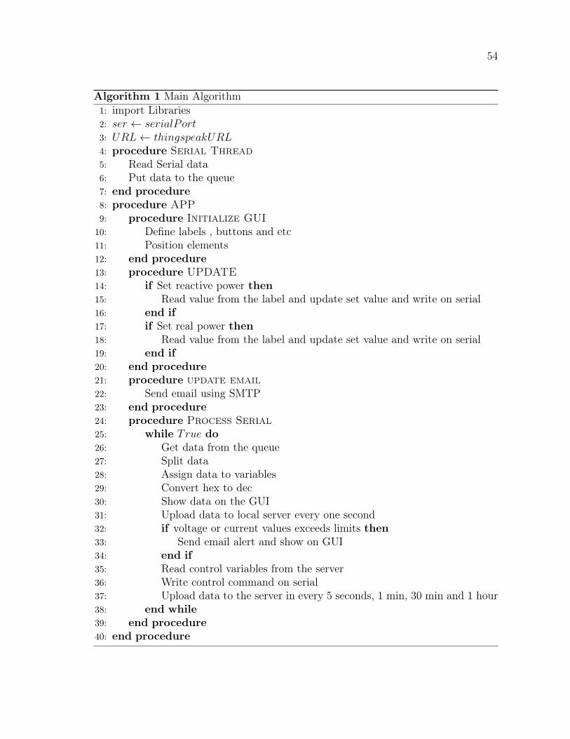
54
Algorithm 1 Main Algorithm1: import Libraries2: ser ← serialPort3: URL← thingspeakURL4: procedure Serial Thread5: Read Serial data6: Put data to the queue7: end procedure8: procedure APP9: procedure Initialize GUI
10: Define labels , buttons and etc11: Position elements12: end procedure13: procedure UPDATE14: if Set reactive power then15: Read value from the label and update set value and write on serial16: end if17: if Set real power then18: Read value from the label and update set value and write on serial19: end if20: end procedure21: procedure update email22: Send email using SMTP23: end procedure24: procedure Process Serial25: while True do26: Get data from the queue27: Split data28: Assign data to variables29: Convert hex to dec30: Show data on the GUI31: Upload data to local server every one second32: if voltage or current values exceeds limits then33: Send email alert and show on GUI34: end if35: Read control variables from the server36: Write control command on serial37: Upload data to the server in every 5 seconds, 1 min, 30 min and 1 hour38: end while39: end procedure40: end procedure
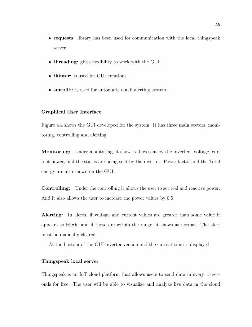
55
• requests: library has been used for communication with the local thingspeak
server.
• threading: gives flexibility to work with the GUI.
• tkinter: is used for GUI creations.
• smtplib: is used for automatic email alerting system.
Graphical User Interface
Figure 4.4 shows the GUI developed for the system. It has three main sectors, moni-
toring, controlling and alerting.
Monitoring: Under monitoring, it shows values sent by the inverter. Voltage, cur-
rent power, and the status are being sent by the inverter. Power factor and the Total
energy are also shown on the GUI.
Controlling: Under the controlling it allows the user to set real and reactive power.
And it also allows the user to increase the power values by 0.5.
Alerting: In alerts, if voltage and current values are greater than some value it
appears as High, and if those are within the range, it shows as normal. The alert
must be manually cleared.
At the bottom of the GUI inverter version and the current time is displayed.
Thingspeak local server
Thingspeak is an IoT cloud platform that allows users to send data in every 15 sec-
onds for free. The user will be able to visualize and analyze live data in the cloud
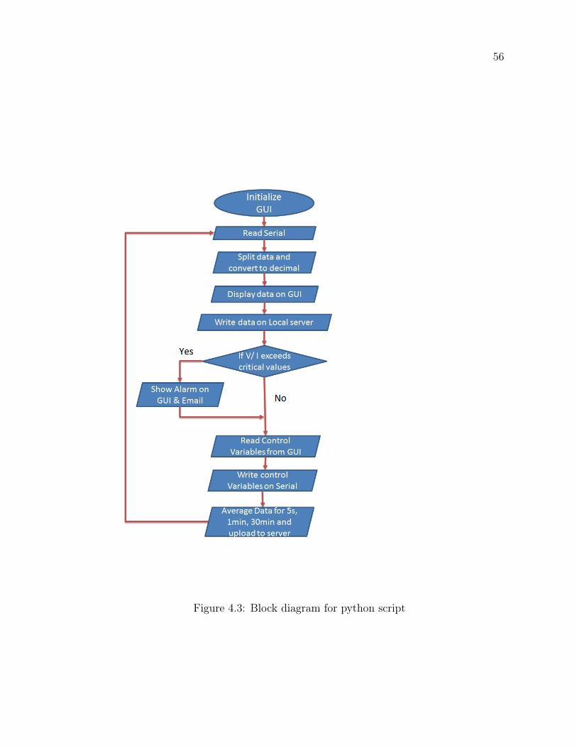
56
Figure 4.3: Block diagram for python script
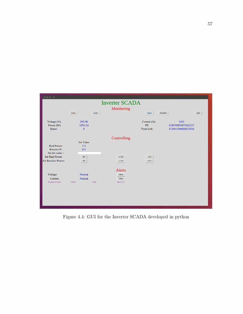
57
Figure 4.4: GUI for the Inverter SCADA developed in python
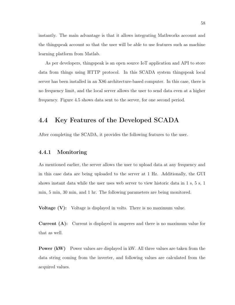
58
instantly. The main advantage is that it allows integrating Mathworks account and
the thingspeak account so that the user will be able to use features such as machine
learning platform from Matlab.
As per developers, thingspeak is an open source IoT application and API to store
data from things using HTTP protocol. In this SCADA system thingspeak local
server has been installed in an X86 architecture-based computer. In this case, there is
no frequency limit, and the local server allows the user to send data even at a higher
frequency. Figure 4.5 shows data sent to the server, for one second period.
4.4 Key Features of the Developed SCADA
After completing the SCADA, it provides the following features to the user.
4.4.1 Monitoring
As mentioned earlier, the server allows the user to upload data at any frequency and
in this case data are being uploaded to the server at 1 Hz. Additionally, the GUI
shows instant data while the user uses web server to view historic data in 1 s, 5 s, 1
min, 5 min, 30 min, and 1 hr. The following parameters are being monitored.
Voltage (V): Voltage is displayed in volts. There is no maximum value.
Current (A): Current is displayed in amperes and there is no maximum value for
that as well.
Power (kW) Power values are displayed in kW. All three values are taken from the
data string coming from the inverter, and following values are calculated from the
acquired values.
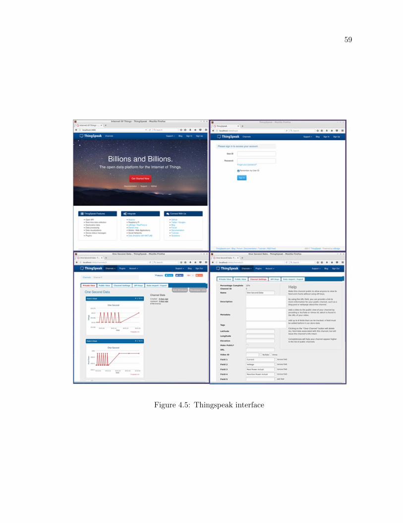
59
Figure 4.5: Thingspeak interface
60
Power Factor: Power factor is calculated using basic power factor equations 4.1
and 4.2.
PF : Power factor
Pr : Real Power
Papp : Apparent power
V Voltage
I : Current
PF =Preal
PApparent
(4.1)
PApparent = V × I (4.2)
Energy (kWh) Energy is displayed in kWh and is calculated using the equation
4.3. The energy displayed is the accumulated energy from the last restart of the in-
verter and value is shown in kWh.
Et : Energy at time “t”
Pt : Power at time “t”
∆t Time interval between two successful power readings
En = En−1 + Pt∆t (4.3)
4.4.2 Controlling
Control access has only been given through the server computer due to security rea-
sons. The person who can log into the server computer using an authorized username
61
and password will only be able to update controlling parameters. The authorized
person will be able to set real power, and reactive power values and that person will
also be able to increase or decrease the set value by 0.5 for smooth operation.
4.4.3 Reporting and alerting
The user will be able to download data at 1 sec, 5 sec, 1 min, 30 min and 1-hour
interval data sets while it is advisable to download lower frequency data reports such
as 1 hour and 30 min due to the high sizes of files. When it comes to alarming and
altering, the main program monitors data values and if current values are higher than
a specific value and it sends an email alert to the user mentioning that the current
value is high. The same logic is applied for the voltage as well. One hour data is kept
public so that everyone on the local area network can view 1-hour data. However,
only an authorized person will be able to see other data levels.
4.5 Testing
As mentioned in the introduction this research is being funded by the NSERC Energy
Storage Network fund. Under the theme 2 with the objective of development of power
converters for Energy Storage systems, the project 2.4 which is conduced in the MUN
is to develop low cost SCADA system for power converter developed in the University
of New Brunswick (UNB).
At the end of the development of the system, it has been tested with the inverter
developed in UNB Sustainable Power Research Lab. They are using a DSP2407A
board for communication purposes with the inverter and that has a RS232 port for
UART communication. The inverter side of the developed communication channel
has been connected to the serial port. Data string sent by the inverter according the
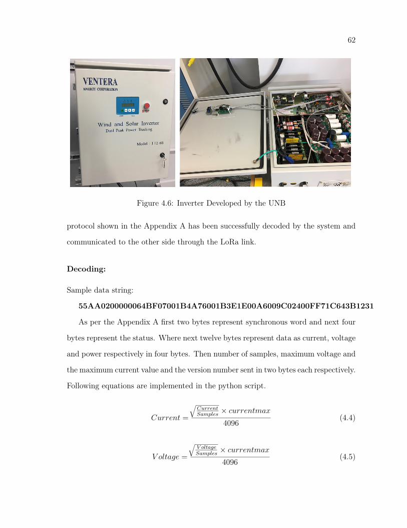
62
Figure 4.6: Inverter Developed by the UNB
protocol shown in the Appendix A has been successfully decoded by the system and
communicated to the other side through the LoRa link.
Decoding:
Sample data string:
55AA0200000064BF07001B4A76001B3E1E00A6009C02400FF71C643B1231
As per the Appendix A first two bytes represent synchronous word and next four
bytes represent the status. Where next twelve bytes represent data as current, voltage
and power respectively in four bytes. Then number of samples, maximum voltage and
the maximum current value and the version number sent in two bytes each respectively.
Following equations are implemented in the python script.
Current =
√CurrentSamples
× currentmax4096
(4.4)
V oltage =
√V oltageSamples
× currentmax4096
(4.5)
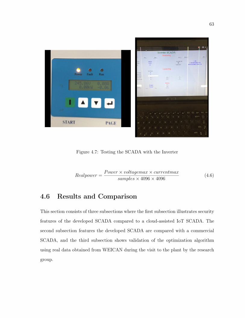
63
Figure 4.7: Testing the SCADA with the Inverter
Realpower =Power × voltagemax× currentmax
samples× 4096× 4096(4.6)
4.6 Results and Comparison
This section consists of three subsections where the first subsection illustrates security
features of the developed SCADA compared to a cloud-assisted IoT SCADA. The
second subsection features the developed SCADA are compared with a commercial
SCADA, and the third subsection shows validation of the optimization algorithm
using real data obtained from WEICAN during the visit to the plant by the research
group.
64
4.6.1 Cloud assisted IoT SCADA Vs. Developed SCADA (Se-
curity features)
As illustrated by A. Sajid et al. [45] there are few security issues in cloud supported
IoT SCADA systems when a third party provides the cloud service. However, in the
developed system the cloud is locally installed. The following subsection compares
the designed system with a cloud-assisted SCADA.
Data Logging: As mentioned in the [45], security risk related to data logging is
high due to logging data in a cloud than logging data locally. This issue has been
overcome in the developed Inverter SCADA by locally installing the IoT server.
Ownership: As per the paper when third-party cloud service provider comes into
the picture ownership of data can become a problem. That ownership issue has also
been overcome by using a local server.
Authentication and encryption: Another issue that has been identified is lack
of authentication and encryption. In the developed SCADA system authentication
has been assured by username and a password for the IoT server for monitoring
purposes. To control the inverter, the user needs to login into the server computer
using a separate username and password. Monitoring server and controlling parts
are made of two isolated systems, and it has increased the security of the SCADA
rather than providing controlling through the same server. Another problem that is
emphasized is lack of encryption where an attacker gets the IP address it makes super
easier for an attacker to hack into the system. Since this system runs on a local server
after closing all ports using a firewall, it will be difficult for attackers to hack into the
system.
The developed SCADA is much more secure than a cloud-assisted IoT based sys-
tem because, in the improved system the server is locally installed and it provides
65
hierarchical authentication for controlling.
4.6.2 Commercial SCADA vs. Developed SCADA
After developing the SCADA, it has been able to communicate with the inverter (in
this case Arduino Uno has been used as a replacement for the inverter with 9600bps),
and all claimed features are being tested and achieved in the laboratory environment.
To bench mark the developed SCADA, it is compared with commercially available
software that has been used by WEICAN for their monitoring and controlling of
their wind farm and the BESS. Table 4.1 illustrates the comparison. Although it
is compared with VTSCADA the proposed SCADA is not a replacement for the
VTSCADA system. Additionally, proposed system does not have costs associated
with any operator panels, alarm hardware and distributed control elements that are
part of the VTSCADA system installed on site. During the comparison it is assumed
that the developed this SCADA system is provided free to the end user. It is also
assumed that the implementation of the proposed system on the side is done for free
at 0 installation cost, and thereâĂŹs an expert user at site to attend to the system
when needed at zero cost.
4.7 Conclusion
This chapter documents the development of a SCADA using an open source Things-
peak local server for monitoring and controlling of inverters. The main features offered
by the SCADA system are discussed. It also shows that the security of the system
is higher compared to a cloud-assisted IoT based SCADA due to some reasons. Fea-
tures of the developed system are compared with a conventional SCADA system used
in WEICAN and identified that other than the low cost the developed system has
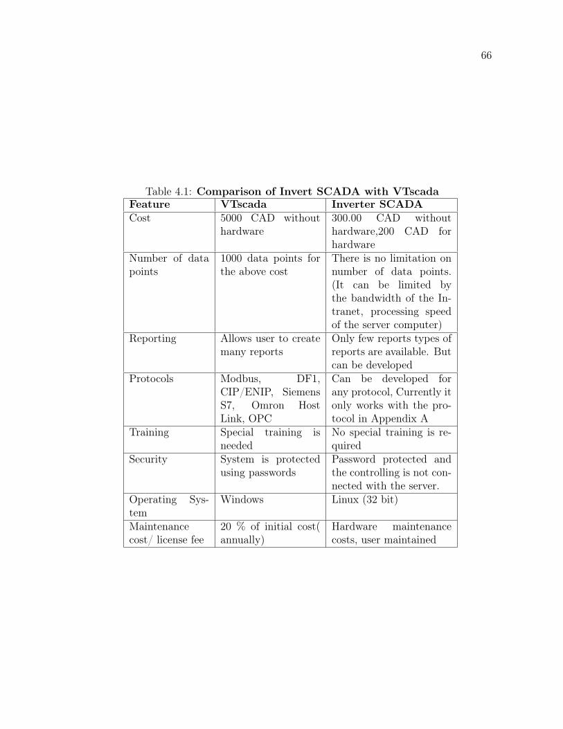
66
Table 4.1: Comparison of Invert SCADA with VTscadaFeature VTscada Inverter SCADACost 5000 CAD without
hardware300.00 CAD withouthardware,200 CAD forhardware
Number of datapoints
1000 data points forthe above cost
There is no limitation onnumber of data points.(It can be limited bythe bandwidth of the In-tranet, processing speedof the server computer)
Reporting Allows user to createmany reports
Only few reports types ofreports are available. Butcan be developed
Protocols Modbus, DF1,CIP/ENIP, SiemensS7, Omron HostLink, OPC
Can be developed forany protocol, Currently itonly works with the pro-tocol in Appendix A
Training Special training isneeded
No special training is re-quired
Security System is protectedusing passwords
Password protected andthe controlling is not con-nected with the server.
Operating Sys-tem
Windows Linux (32 bit)
Maintenancecost/ license fee
20 % of initial cost(annually)
Hardware maintenancecosts, user maintained
67
some superior features compared with the commercial SCADA. Finally, the devel-
oped SCADA has been tested with using a real Inverter developed in the UNB.
Chapter 5
Control Strategies for Remote
Control of a Grid Tie Inverter and Its
implementation using Low-Cost
SCADA system
5.1 Introduction
The primary objective of this chapter is to develop an algorithm to maximize the
profit generated by a battery energy storage which is connected to a wind turbine and
to implement the algorithm on a cloud assisted IoT server to automate the dispatching
of the battery energy storage. Linear programming based algorithm is developed to
maximize the revenue. Accuweather API based novel approach is used to implement
the algorithm in a Python based program and uploaded data to a local thingpseak
server so that the inverter can obtain data for controlling as well as to convey to the
dispatching center.
69
Predictive wind farming is an emerging topic with the increasing population of
wind farms and a grid. It is possible to improve the quality of the power exported
by a wind farm by integrating an energy storage system. According to the Global
Wind Report, installed wind capacity in 2015 is 432.9 GW around the globe and it
is expected to become 792.1 GW by 2020 [1]. Energy storage systems are becoming
increasingly popular as a result of cost reduction and improvements in technologies.
At the present, the term, energy storage is more often used and many researches are
being conducted to develop new methodologies. Many technologies are being used for
energy storages where pump hydro dominates as technology. Due to mass production
and developments in battery cell technologies BESS are emerging as a promising
technology with number of advantages over other storage methods. When BESS
installed in a wind farm it will be costly if the BESS is charged when wind turbines
are not producing energy. Study has been carried out by Wind Energy Institute
Canada situated in Prince Edward Island (WEICAN PEI) using their existing Wind
park and the battery energy storage. From the study it shows that when wind power
does not exist it is more profitable to use stored energy in BESS for auxiliary power
needs. Therefore, depending on the wind availability in the next few hours State of
Charge (SoC) of the BESS has to be decided.
Therefore, optimum operation scheduling of energy storage system is most im-
portant in an economic perspective because most of the energy storages like battery
energy storage systems have a specific number of cycles. In order to get the maximum
profit out of it, energy storage needs to be optimally controlled while using each cycle
to maximize the profit.
The chapter is organized as follows, Section 5.2 defines the problem with clear
boundaries. In section 5.4 the algorithm is validated with using actual data from
70
WEICAN. Finally, in section 5.5, the chapter is concluded with future recommenda-
tions.
5.2 Problem Statement
Although much literature can be found on optimum controlling of BESS using different
approaches, there is a gap in the BESS controlling field for optimization based on wind
availability for future hours.
5.2.1 Problem formulation
To formulate the problem, wind turbine arrangement in WEICAN is considered. Lay-
out for the WEICAN with 5 wind turbines and Figure 5.1 illustrates a configuration
of a wind park which has five 2 MW turbines and a battery bank with 1 MW/ 2
MWh. An objective of the algorithm developed is to achieve the minimum cost of
generation and to get maximum profit when wind speed is available for a week.
In order to maximize the profit, objective function can be modeled as follows,
Bt Electricity selling or purchasing price at time “t”
Pt Power at Common coupling point at time “t”
ObjectiveFunction =72∑n=1
BtPt (5.1)
Power at the common coupling point (CCP) is given by the Pt and the equation 5.2
shows the power calculation. Power consumed for ancillary activities are represented
by the PLoads.
Pwt Wind power generation for time “t”
Pdis Discharging power of BESS at time “t”
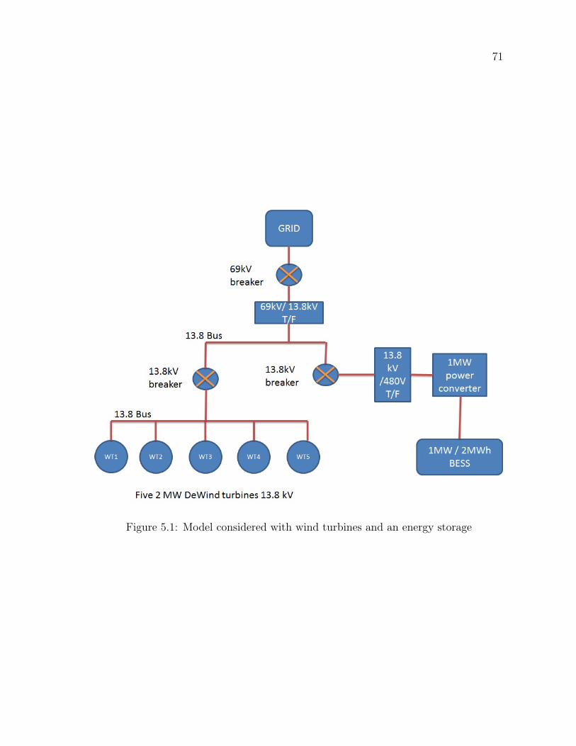
71
Figure 5.1: Model considered with wind turbines and an energy storage
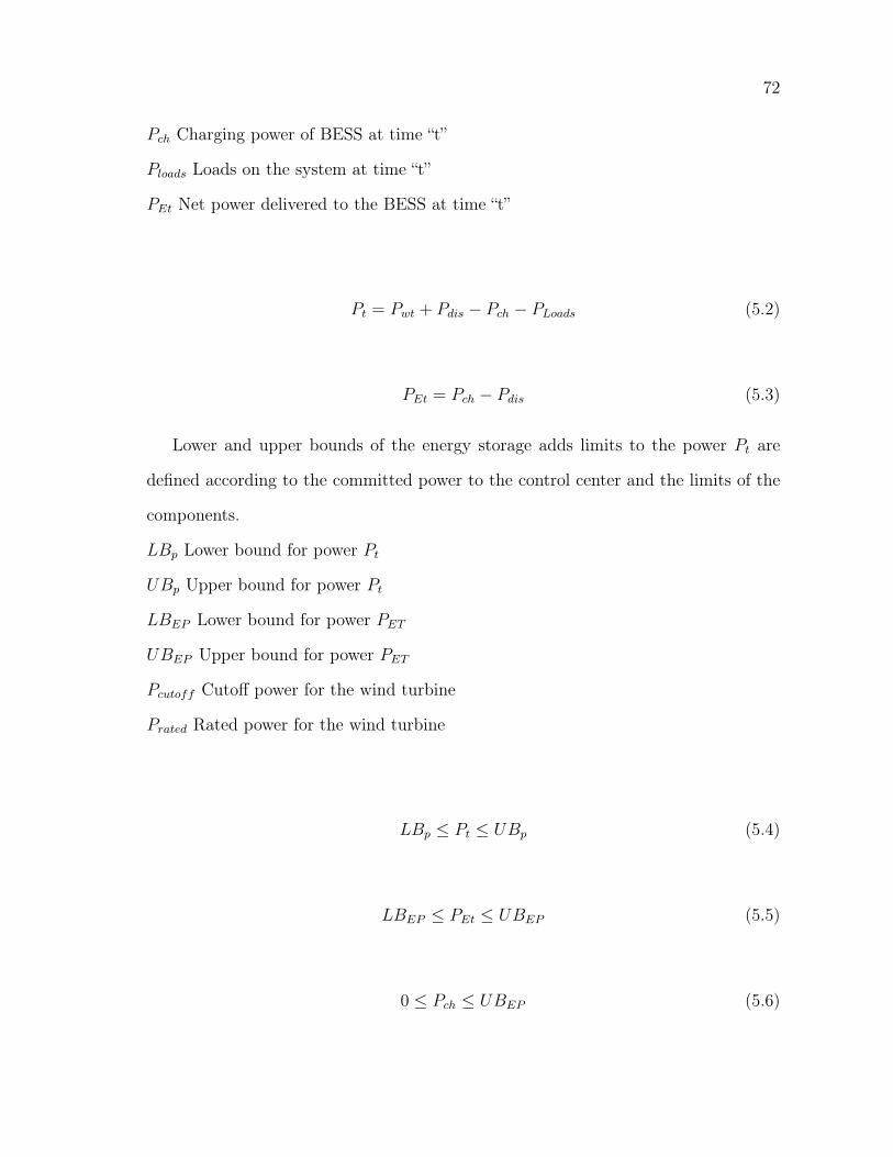
72
Pch Charging power of BESS at time “t”
Ploads Loads on the system at time “t”
PEt Net power delivered to the BESS at time “t”
Pt = Pwt + Pdis − Pch − PLoads (5.2)
PEt = Pch − Pdis (5.3)
Lower and upper bounds of the energy storage adds limits to the power Pt are
defined according to the committed power to the control center and the limits of the
components.
LBp Lower bound for power Pt
UBp Upper bound for power Pt
LBEP Lower bound for power PET
UBEP Upper bound for power PET
Pcutoff Cutoff power for the wind turbine
Prated Rated power for the wind turbine
LBp ≤ Pt ≤ UBp (5.4)
LBEP ≤ PEt ≤ UBEP (5.5)
0 ≤ Pch ≤ UBEP (5.6)
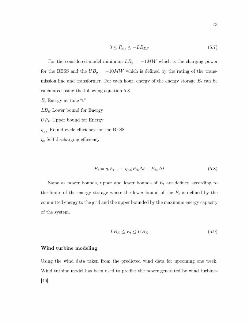
73
0 ≤ Pdis ≤ −LBEP (5.7)
For the considered model minimum LBp = −1MW which is the charging power
for the BESS and the UBp = +10MW which is defined by the rating of the trans-
mission line and transformer. For each hour, energy of the energy storage Et can be
calculated using the following equation 5.8.
Et Energy at time “t”
LBE Lower bound for Energy
UPE Upper bound for Energy
ηES
Round cycle efficiency for the BESS
ηe Self discharging efficiency
Et = ηeEt−1 + ηESPch∆t− Pdis∆t (5.8)
Same as power bounds, upper and lower bounds of Et are defined according to
the limits of the energy storage where the lower bound of the Et is defined by the
committed energy to the grid and the upper bounded by the maximum energy capacity
of the system.
LBE ≤ Et ≤ UBE (5.9)
Wind turbine modeling
Using the wind data taken from the predicted wind data for upcoming one week.
Wind turbine model has been used to predict the power generated by wind turbines
[46].
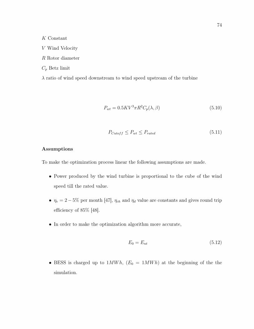
74
K Constant
V Wind Velocity
R Rotor diameter
Cp Betz limit
λ ratio of wind speed downstream to wind speed upstream of the turbine
Pwt = 0.5KV 3πR2Cp(λ, β) (5.10)
PCutoff ≤ Pwt ≤ Prated (5.11)
Assumptions
To make the optimization process linear the following assumptions are made.
• Power produced by the wind turbine is proportional to the cube of the wind
speed till the rated value.
• ηe = 2− 5% per month [47], ηch and ηd value are constants and gives round trip
efficiency of 85% [48].
• In order to make the optimization algorithm more accurate,
E0 = Ent (5.12)
• BESS is charged up to 1MWh, (E0 = 1MWh) at the beginning of the the
simulation.
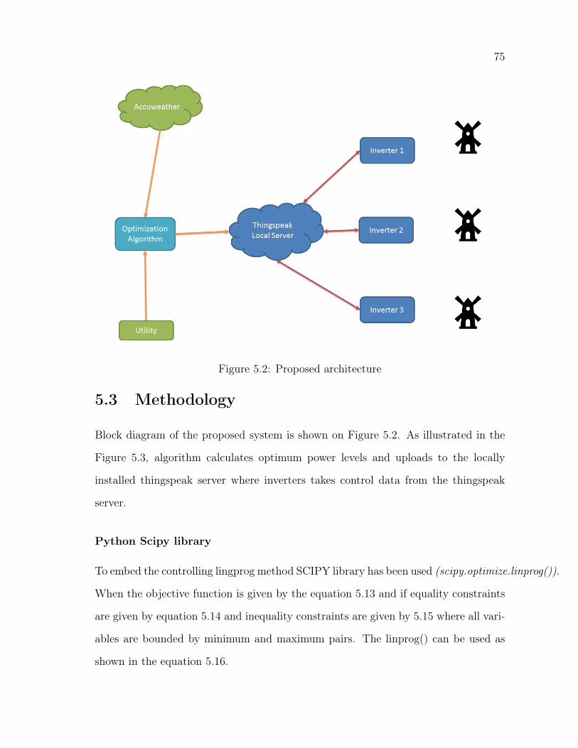
75
Figure 5.2: Proposed architecture
5.3 Methodology
Block diagram of the proposed system is shown on Figure 5.2. As illustrated in the
Figure 5.3, algorithm calculates optimum power levels and uploads to the locally
installed thingspeak server where inverters takes control data from the thingspeak
server.
Python Scipy library
To embed the controlling lingprog method SCIPY library has been used (scipy.optimize.linprog()).
When the objective function is given by the equation 5.13 and if equality constraints
are given by equation 5.14 and inequality constraints are given by 5.15 where all vari-
ables are bounded by minimum and maximum pairs. The linprog() can be used as
shown in the equation 5.16.
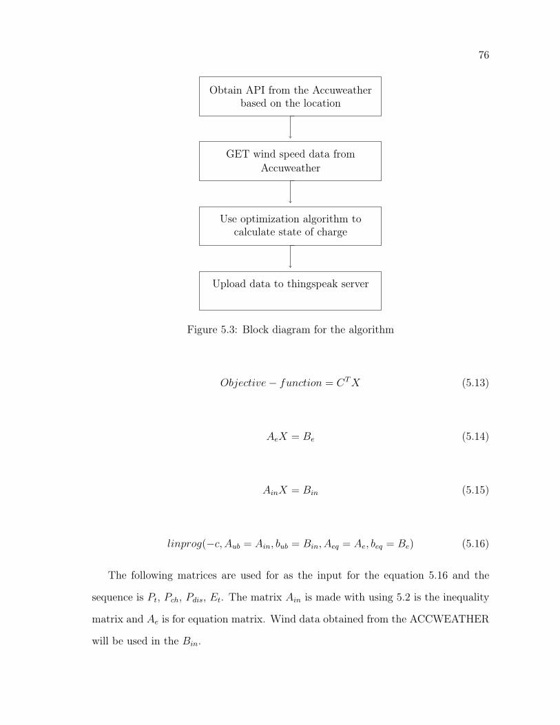
76
Obtain API from the Accuweatherbased on the location
GET wind speed data fromAccuweather
Use optimization algorithm tocalculate state of charge
Upload data to thingspeak server
Figure 5.3: Block diagram for the algorithm
Objective− function = CTX (5.13)
AeX = Be (5.14)
AinX = Bin (5.15)
linprog(−c, Aub = Ain, bub = Bin, Aeq = Ae, beq = Be) (5.16)
The following matrices are used for as the input for the equation 5.16 and the
sequence is Pt, Pch, Pdis, Et. The matrix Ain is made with using 5.2 is the inequality
matrix and Ae is for equation matrix. Wind data obtained from the ACCWEATHER
will be used in the Bin.
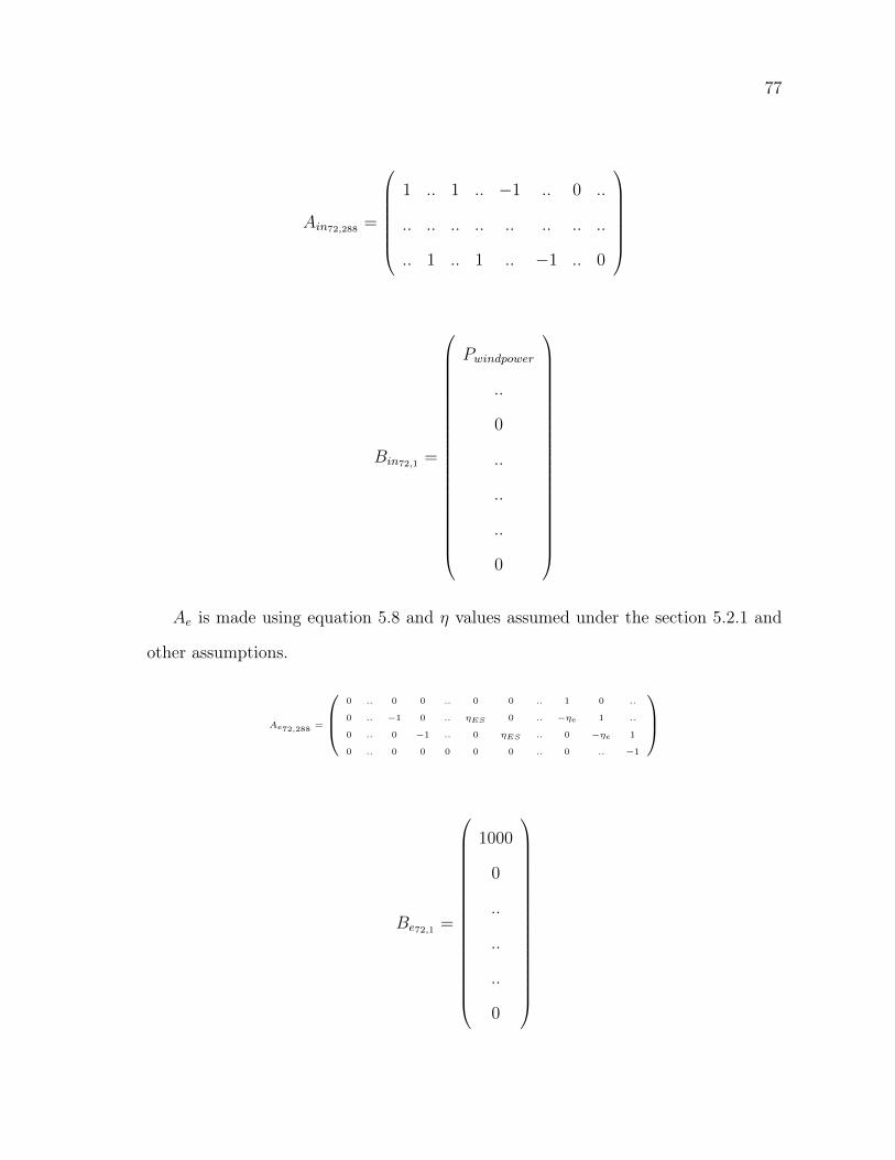
77
Ain72,288 =
1 .. 1 .. −1 .. 0 ..
.. .. .. .. .. .. .. ..
.. 1 .. 1 .. −1 .. 0
Bin72,1 =
Pwindpower
..
0
..
..
..
0
Ae is made using equation 5.8 and η values assumed under the section 5.2.1 and
other assumptions.
Ae72,288 =
0 .. 0 0 .. 0 0 .. 1 0 ..
0 .. −1 0 .. ηES 0 .. −ηe 1 ..
0 .. 0 −1 .. 0 ηES .. 0 −ηe 1
0 .. 0 0 0 0 0 .. 0 .. −1
Be72,1 =
1000
0
..
..
..
0
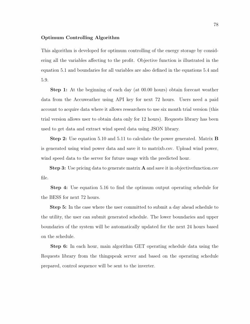
78
Optimum Controlling Algorithm
This algorithm is developed for optimum controlling of the energy storage by consid-
ering all the variables affecting to the profit. Objective function is illustrated in the
equation 5.1 and boundaries for all variables are also defined in the equations 5.4 and
5.9.
Step 1: At the beginning of each day (at 00.00 hours) obtain forecast weather
data from the Accuweather using API key for next 72 hours. Users need a paid
account to acquire data where it allows researchers to use six month trial version (this
trial version allows user to obtain data only for 12 hours). Requests library has been
used to get data and extract wind speed data using JSON library.
Step 2: Use equation 5.10 and 5.11 to calculate the power generated. Matrix B
is generated using wind power data and save it to matrixb.csv. Upload wind power,
wind speed data to the server for future usage with the predicted hour.
Step 3: Use pricing data to generate matrixA and save it in objectivefunction.csv
file.
Step 4: Use equation 5.16 to find the optimum output operating schedule for
the BESS for next 72 hours.
Step 5: In the case where the user committed to submit a day ahead schedule to
the utility, the user can submit generated schedule. The lower boundaries and upper
boundaries of the system will be automatically updated for the next 24 hours based
on the schedule.
Step 6: In each hour, main algorithm GET operating schedule data using the
Requests library from the thingspeak server and based on the operating schedule
prepared, control sequence will be sent to the inverter.
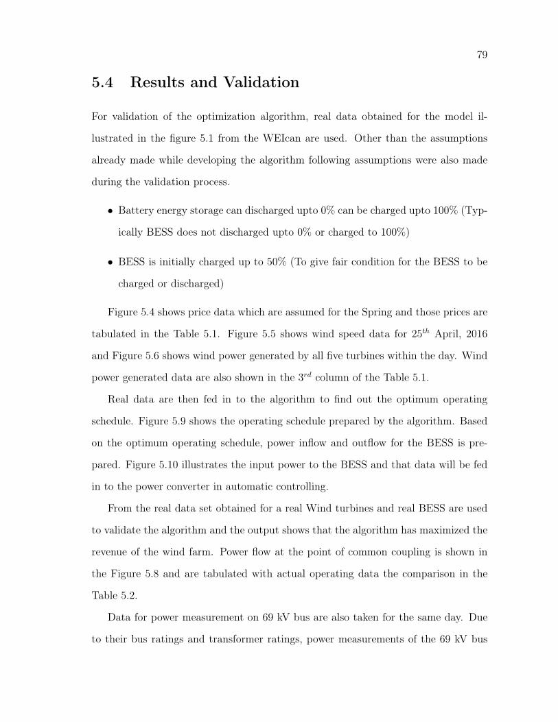
79
5.4 Results and Validation
For validation of the optimization algorithm, real data obtained for the model il-
lustrated in the figure 5.1 from the WEIcan are used. Other than the assumptions
already made while developing the algorithm following assumptions were also made
during the validation process.
• Battery energy storage can discharged upto 0% can be charged upto 100% (Typ-
ically BESS does not discharged upto 0% or charged to 100%)
• BESS is initially charged up to 50% (To give fair condition for the BESS to be
charged or discharged)
Figure 5.4 shows price data which are assumed for the Spring and those prices are
tabulated in the Table 5.1. Figure 5.5 shows wind speed data for 25th April, 2016
and Figure 5.6 shows wind power generated by all five turbines within the day. Wind
power generated data are also shown in the 3rd column of the Table 5.1.
Real data are then fed in to the algorithm to find out the optimum operating
schedule. Figure 5.9 shows the operating schedule prepared by the algorithm. Based
on the optimum operating schedule, power inflow and outflow for the BESS is pre-
pared. Figure 5.10 illustrates the input power to the BESS and that data will be fed
in to the power converter in automatic controlling.
From the real data set obtained for a real Wind turbines and real BESS are used
to validate the algorithm and the output shows that the algorithm has maximized the
revenue of the wind farm. Power flow at the point of common coupling is shown in
the Figure 5.8 and are tabulated with actual operating data the comparison in the
Table 5.2.
Data for power measurement on 69 kV bus are also taken for the same day. Due
to their bus ratings and transformer ratings, power measurements of the 69 kV bus
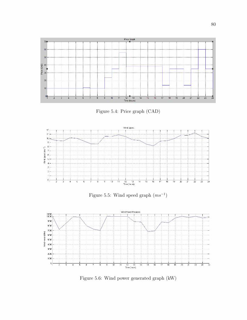
80
Figure 5.4: Price graph (CAD)
Figure 5.5: Wind speed graph (ms−1)
Figure 5.6: Wind power generated graph (kW)
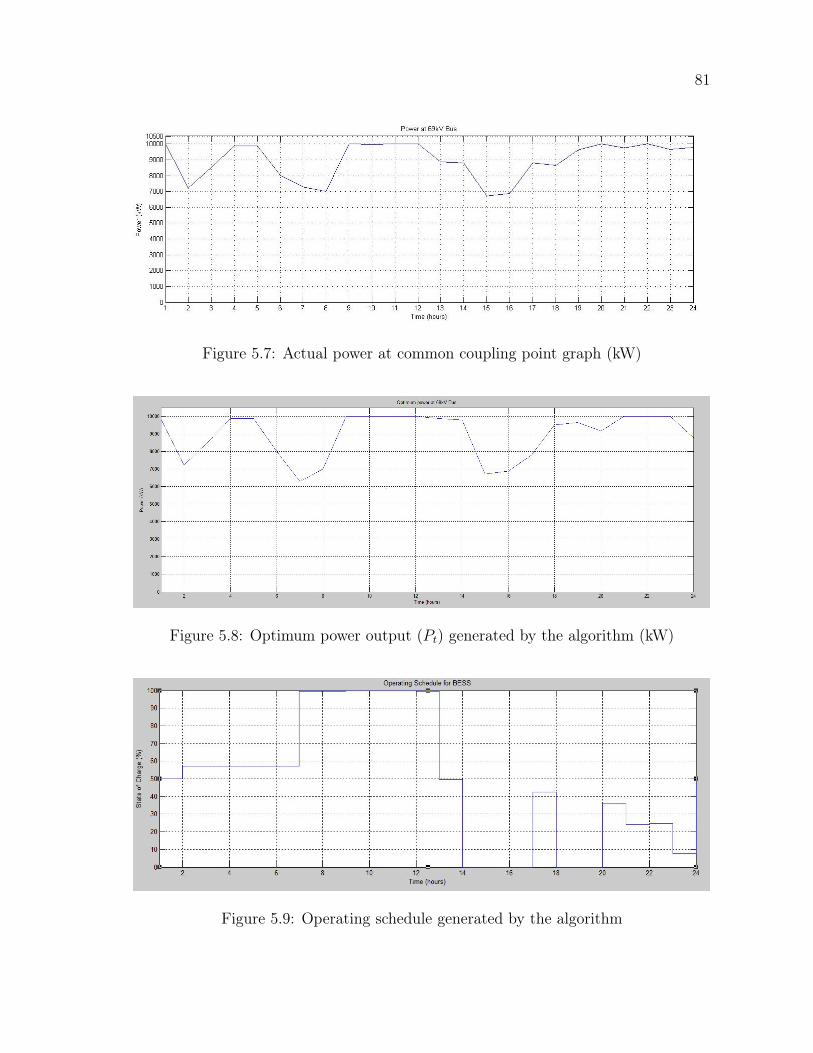
81
Figure 5.7: Actual power at common coupling point graph (kW)
Figure 5.8: Optimum power output (Pt) generated by the algorithm (kW)
Figure 5.9: Operating schedule generated by the algorithm
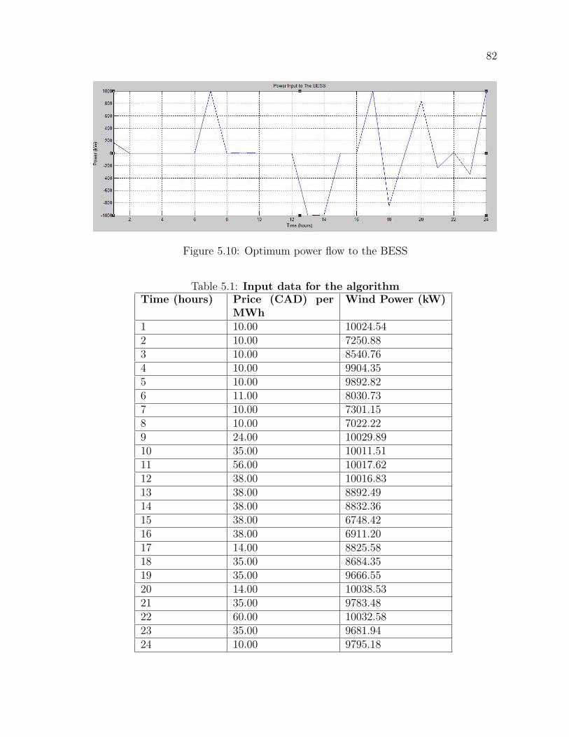
82
Figure 5.10: Optimum power flow to the BESS
Table 5.1: Input data for the algorithmTime (hours) Price (CAD) per
MWhWind Power (kW)
1 10.00 10024.542 10.00 7250.883 10.00 8540.764 10.00 9904.355 10.00 9892.826 11.00 8030.737 10.00 7301.158 10.00 7022.229 24.00 10029.8910 35.00 10011.5111 56.00 10017.6212 38.00 10016.8313 38.00 8892.4914 38.00 8832.3615 38.00 6748.4216 38.00 6911.2017 14.00 8825.5818 35.00 8684.3519 35.00 9666.5520 14.00 10038.5321 35.00 9783.4822 60.00 10032.5823 35.00 9681.9424 10.00 9795.18
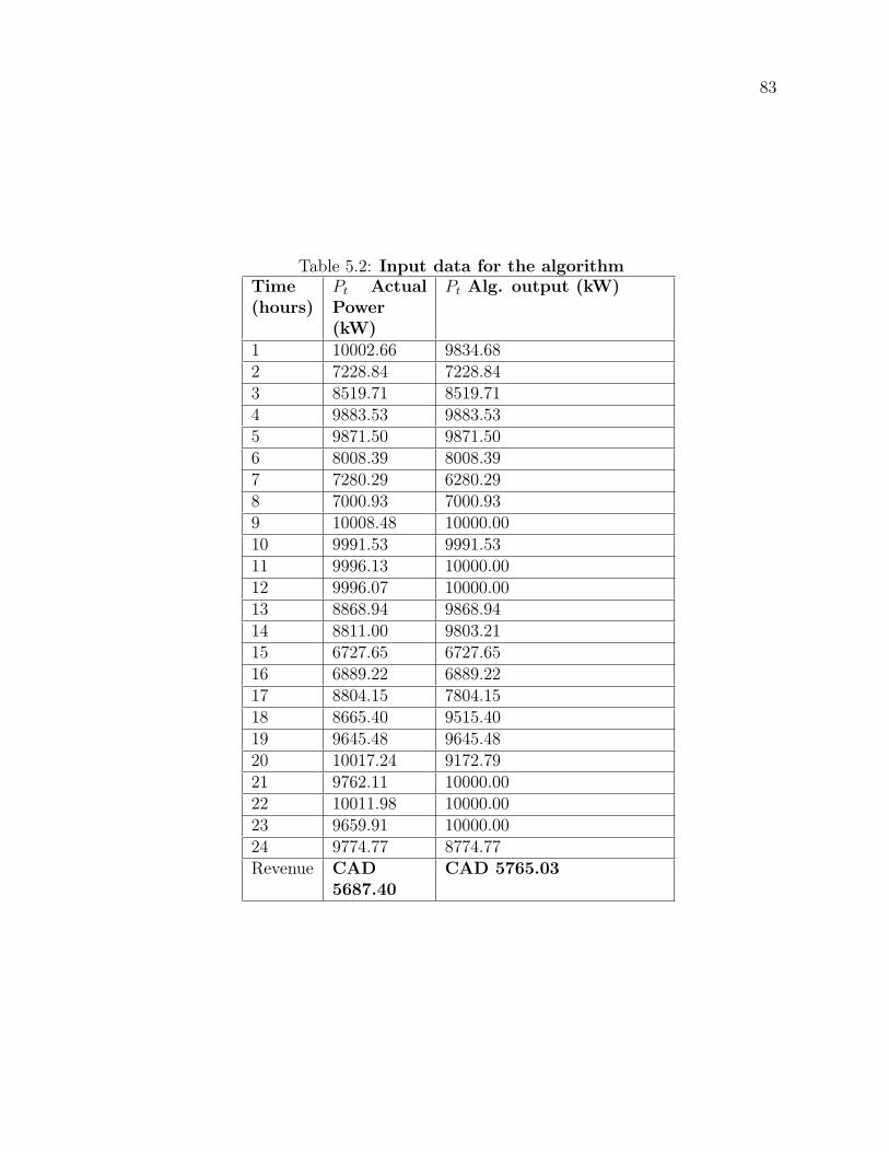
83
Table 5.2: Input data for the algorithmTime(hours)
Pt ActualPower(kW)
Pt Alg. output (kW)
1 10002.66 9834.682 7228.84 7228.843 8519.71 8519.714 9883.53 9883.535 9871.50 9871.506 8008.39 8008.397 7280.29 6280.298 7000.93 7000.939 10008.48 10000.0010 9991.53 9991.5311 9996.13 10000.0012 9996.07 10000.0013 8868.94 9868.9414 8811.00 9803.2115 6727.65 6727.6516 6889.22 6889.2217 8804.15 7804.1518 8665.40 9515.4019 9645.48 9645.4820 10017.24 9172.7921 9762.11 10000.0022 10011.98 10000.0023 9659.91 10000.0024 9774.77 8774.77Revenue CAD
5687.40CAD 5765.03
84
was similar to the wind power changes. That means the control strategy actually
followed does not use the battery bank to improve profits. As illustrated in Table 5.2
new algorithm optimize the output of the system by storing energy in the low price
periods to sell in the high demand periods. In the row one and seven of Table 5.2
algorithm sells less than the actual power because then power can be sold at later
hour with high prices. As per the assumption, the battery is initially charged to 1
MWh, and it can get 1 MWh energy. Therefore, at the 7th hour, it will keep 1000
kwh to sell at the 13th hour which has a higher price. The Same thing is happening
in the 17th hour and the 18th hour as well.
Observing row eleven to twenty four, it can concludes that the algorithm has been
able to maximize the profit by selling power at high price regions by storing from low
pricing regions.
In the last row of the Table 5.2 illustrates the revenue generated by each method
that was calculated using the pricing data shown in the second column of Table 5.1. It
shows that revenue generated with the operating schedule produced by the algorithm
is higher than the actual revenue generated where it could have been increased by
adding a revenue optimization algorithm. Figure 5.9 shows the operating schedule
prepared by the algorithm, it show the set value of State of Charge for the battery.
It does not reflect the actual behavior of the BESS.
5.5 Conclusion and future works
This chapter presents a novel implementation of optimal control algorithm for a bat-
tery energy storage system connected with a wind turbine and to a grid. Python
based program has been developed using Accuweather API to gather wind data and
to optimize the revenue and a locally installed thingspeak server has been used for
85
data storage . Performance of the algorithm has been verified using real wind data
obtained from the WEICAN. Results shows that the algorithm has been able to in-
crease the profit by changing the operation schedule considering the wind availability
for next twenty four hours. As a future work, control algorithm will be improved to
use minimize the electricity bill for households by training a neural network to predict
the load pattern for the house and optimally control the BESS.
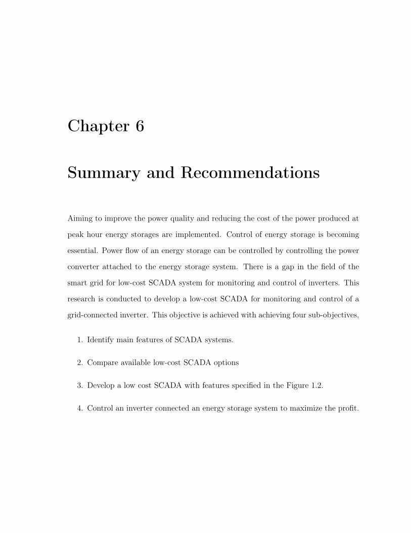
Chapter 6
Summary and Recommendations
Aiming to improve the power quality and reducing the cost of the power produced at
peak hour energy storages are implemented. Control of energy storage is becoming
essential. Power flow of an energy storage can be controlled by controlling the power
converter attached to the energy storage system. There is a gap in the field of the
smart grid for low-cost SCADA system for monitoring and control of inverters. This
research is conducted to develop a low-cost SCADA for monitoring and control of a
grid-connected inverter. This objective is achieved with achieving four sub-objectives,
1. Identify main features of SCADA systems.
2. Compare available low-cost SCADA options
3. Develop a low cost SCADA with features specified in the Figure 1.2.
4. Control an inverter connected an energy storage system to maximize the profit.
87
6.1 Summary
6.1.1 Research Summary Based on Objective 1
Although a sincere dedication has been given to the field of SCADA by the research
community, features of the SCADA system varies with the system that is monitored by
the SCADA. Therefore, initially, research has been conducted to recognize elements of
a SCADA system. Based on that features needs to be embedded in a SCADA system
that would be used for monitoring control of a SCADA system have been recognized
and documented.
6.1.2 Research Summary Based on Objective 2
Based on features recognized under the objective one, few SCADA systems were
selected and tested to verify their suitability for the application. Based on the results
of the tests local thingspeak based local cloud assisted SCADA has been identified as
the most suitable technology to fulfill the objective.
6.1.3 Research Summary Based on Objective 3
Then, a SCADA has been developed using the open source Thingspeak local server
for monitoring and controlling of inverters. The usage of open source software reduces
the cost while keeping the security and the reliability at a higher level. The python
based program allows the user to obtain data from the serial port and posts data
on the thingspeak server and the user is allowed to view and upload data from the
server. A graphical user interface has been developed to interact with the SCADA
system, and it shows current data values and allows the user to set the controlling
variables. During the field testing the developed python-based program has been able
88
to communicate successfully with an inverter and post data to the server.
6.1.4 Research Summary Based on Objective 4
Finally, the thesis developed a linear programming based controlling strategy designed
for a SCADA system to control a grid-connected inverter which is used to interface a
battery energy storage with the grid. To control the inverter, a predictive wind speed
algorithm is proposed where parameters are being automatically set by the linear
programming based optimization algorithm that can be embedded into the SCADA
system utilized for the inverter. The algorithm intends to take pricing data from
the utility and obtain wind speed data from the Accuweather to generate operating
schedule for the battery bank to maximize the revenue. Real data collected from
the Wind Energy Institute Canada (WEIcan) are used to validate the controlling
algorithm, and the results emphasize that the algorithm has produced the optimum
operating schedule while maximizing the profit.
6.2 Significant Contributions
As a summary, this thesis has made following key contributions in the field of SCADA
systems by fulfilling all of the outlined research objectives,
1. Recognized and documented core features that needs to be embedded in a
SCADA which are used for monitoring and control of an inverter.
2. Developed a low cost open source SCADA for monitoring and control of a grid
connected inverter.
3. Developed an optimization algorithm to maximize the profit generated by an
energy storage.
89
6.3 Directions for Future Work
• The primary objective of the research is to develop a low-cost SCADA system.
The implemented SCADA server consumes around 52VA which is high and
not suitable for small-scale energy storages. Therefore, the server needs to be
installed in a low power consumption computer and test it.
• The developed system communicates only with the given protocol. Therefore,
the system needs to be improved with more protocols. Since the AI filed and
machine learning is enhancing AI bot can be attached to the SCADA.
• Optimum usage of home energy storage control algorithm will be improved to
use to minimize the electricity bill for households by training a neural network
to predict the load pattern for the house and optimally control the BESS.
6.4 List of Publications
All the contributions in the thesis are published in the following technical papers and
posters:
Journal Articles
1. Sarinda Jayasinghe, Tariq Iqbal and George K Mann, An Internet of Things
based open SCADA for Monitoring and Controlling of Inverters, prepared for
submission.
Peer-reviewed Conference Articles
2. Jayasinghe L. Sarinda, Tariq Iqbal, George Mann, Low-cost and open source
SCADA options for remote control and monitoring of inverters, presented at
CCECE 2017, Windsor ON Canada.
90
Abstract-reviewed Conference Articles
3. Sarinda Jayasinghe, Tariq Iqbal, George Mann, Optimum Control of a Grid
Connected Battery Energy Storage, accepted to present at 26th IEEE NECEC
conference 2017.
4. Sarinda Jayasinghe, Tariq Iqbal, George Mann, IoT based low cost SCADA
system for an inverter, presented at 25th IEEE NECEC conference 2016.
Poster presentations
5. S.L. Jayasinghe, T. Iqbal and G. Mann, Internet of Things (IoT) based open
SCADA for Monitoring and Controlling of Inverters, Poster session presented
at: NESTNet Technical Conference. 1st Annual conference. 21-22 July, 2017;
Toronto, ON.
Bibliography
[1] E. Chemali, M. Preindl, P. Malysz and A. Emadi, "Electrochemical and Elec-trostatic Energy Storage and Management Systems for Electric Drive Vehicles:State-of-the-Art Review and Future Trends," in IEEE Journal of Emerging andSelected Topics in Power Electronics, vol. 4, no. 3, pp. 1117-1134, Sept. 2016.
[2] https://www.ryerson.ca/nestnet/themes/
[3] Ujvarosi, Alexandru. "EVOLUTION OF SCADA SYSTEMS." Bulletin of theTransilvania University of Brasov. Engineering Sciences. Series I 9.1 (2016): 63.
[4] https://www.gogreensolar.com/products/sma-sb-10000tlus-10-sunny-boy-grid-tie-inverter-10000w-with-dc-disconnect
[5] https : //www.alibaba.com/product− detail/SAJ − 10kw − 3− phase− 380V −on60643486889.html?
[6] A. M. Grilo, J. Chen, M. DÃŋaz, D. Garrido and A. Casaca,. 2014. "An In-tegrated WSAN and SCADA System for Monitoring a Critical Infrastructure."(IEEE TRANSACTIONS ON INDUSTRIAL INFORMATICS) 10 (3).
[7] Andreescu, E. H. Gurban and G. D. 2011. "SCADA element solutions using Eth-ernet and mobile phone network." 2011 IEEE 9th International Symposium onIntelligent Systems and Informatics. 303-308.
[8] P. Zhang, T. Liu, Z. X. Yang, Y. Mou, Y. H. Wei and D. Chen,. 2015. "Design ofremote control plug." 2015 IEEE International Conference on Applied Supercon-ductivity and Electromagnetic Devices (ASEMD). 29-30.
[9] S. Sanap, R. Nawale, S. Kapse, A. Kale and M. Korade,. 2015. "Exact virtualiza-tion of Industrial Environment on Web Using SCADA with Artificial Intelligence."Green Computing and Internet of Things (ICGCIoT), 2015 International Confer-ence on, Noida. 99-103.
[10] S. G. Hegde, S. R. Desai, D. R. Gajanan, S. B. Kowligi and Sachin RC. ndustrialInstrumentation and Control (ICIC). "Implementation of SCADA in industriesusing wireless technologies." 2015. Pune.
92
[11] A. Soetedjo, Y. I. Nakhoda and D. Suryadi,. 2013. "Development of data acquisi-tion system for hybrid power plant." QiR (Quality in Research), 2013 InternationalConference on, Yogyakarta, 2013. 197-201.
[12] J. L. Sarinda, T. Iqbal and G. Mann, "Low-cost and open source SCADA optionsfor remote control and monitoring of inverters," 2017 IEEE 30th Canadian Con-ference on Electrical and Computer Engineering (CCECE), Windsor, ON, 2017,pp. 1-4.
[13] Sergi Blanch-Torn, Fernando Cores, Ramiro Moreno Chiral. 2015. "Agent-basedPKI for Distributed Control System." World Congress on Industrial Control Sys-tems Security (WCICSS-2015). 28-35.
[14] Felipe. C, Yeison. C, Leonardo. R,. 2014. "Wireless Sensor System Accordingto the Concept of IoT -Internet of Things." 2014 International Conference onComputational Science and Computational Intelligence.
[15] Pasha, Sharmad. 2016. "Thingspeak Based Sensing and Monitoring System forIoT with Matlab Analysis." International Journal of New Technology and Research(IJNTR) 19-23.
[16] Bonnie Zhu, Anthony Joseph, Shankar Sastry. 2011. "A Taxonomy of CyberAttacks on SCADA Systems." 2011 IEEE International Conferences on Internetof Things, and Cyber, Physical and Social Computing.
[17] Hasan, M., and H. T. Mouftah. 2016. "Optimal Trust System Placement in SmartGrid SCADA Networks." (IEEE Access) PP (99).
[18] D.K. Maly, K.S. Kwan. 1995. "Optimal battery energy storage system (BESS)charge scheduling with dynamic programming." IEE Proceedings - Science, Mea-surement and Technology.
[19] Chin H. Lo, Max D. Anderson. 1999. "Economic dispatch and optimal sizing ofbattery energy storage systems in utility load-leveling operations." IEEE Trans-actions on Energy Conversion.
[20] M. S. Habibi. 2001. "Model for impact of storage on spinning reserve requirementsand distributed generation." Proceedings of the 33rd Southeastern Symposium onSystem Theory 161-165.
[21] Kaye, Thai Doan Hoang Cau and R. J. 2001. "Multiple distributed energy storagescheduling using constructive evolutionary programming." PICA 2001. InnovativeComputing for Power - Electric Energy Meets the Market. 22nd IEEE PowerEngineering Society. International Conference on Power Industry Computer Ap-plications. Sydney. 402-407.
93
[22] L. C. C. Fung. 2000. "Combined fuzzy-logic and genetic algorithm technique forthe scheduling of remote area power system." IEEE Power Engineering SocietyWinter Meeting. 1069-1074.
[23] T. Y. Lee. 2007. "Operating Schedule of Battery Energy Storage System in aTime-of-Use Rate Industrial User With Wind Turbine Generators: A MultipassIteration Particle Swarm Optimization Approach." 774-782.
[24] Shuang Xu, Riming Shao and Liuchen Chang, "Single-phase voltage source in-verter with voltage-boosting and power decoupling capabilities," 2017 IEEE 8thInternational Symposium on Power Electronics for Distributed Generation Sys-tems (PEDG), Florianopolis, 2017, pp. 1-8.
[25] Sarinda Jayasinghe, Tariq Iqbal, George Mann, "IoT based low cost SCADAsystem for an inverter", presented at 25th IEEE NECEC conference 2016.
[26] S. L. Jayasinghe, T. Iqbal and G. Mann, "Internet of Things (IoT) based opensource SCADA for Monitoring and Controlling of Inverters," Poster session pre-sented at: NESTNet Technical Conference. 1st Annual conference. 21-22 July,2017; Toronto, ON.
[27] Sarinda Jayasinghe, Tariq Iqbal and George K Mann, An Internet of Thingsbased open SCADA for Monitoring and Controlling of Inverters, submitted withIEEE Access 2017.
[28] Sarinda Jayasinghe, Tariq Iqbal, George Mann, Optimum Control of a Grid Con-nected Battery Energy Storage, accepted to present at 26th IEEE NECEC con-ference 2017.
[29] D. Watson, C. Hastie and M. Rodgers, "Comparing Different Regulation Of-ferings from a Battery in a Wind RnD Park," in IEEE Transactions on PowerSystems, vol. PP, no. 99, pp. 1-1. doi: 10.1109/TPWRS.2017.2747517
[30] Gerald Giroux, Data Topology, Wind Energy Institute of Canada
[31] 2007. Core IEC Standards. 05 15. Accessed 2016.http://www.iec.ch/smartgrid/standards/.
[32] https://www.trihedral.com/scada-software-pricing
[33] M. N. Ashraf, S. A. B. Khalid, M. S. Ahmed and A. Munir,. 2009. "Implemen-tation of Intranet-SCADA Using LabVIEW Based Data Acquisition and Man-agement." Computing, Engineering and Information, 2009. ICC ’09. InternationalConference on, Fullerton, CA. IEEE. 244-249.
94
[34] ANAM. S, HAIDER. A, KASHIF. S. 2016. "Cloud-Assisted IoT-Based SCADASystems Security: A Review of the State of the Art and Future Challenges."(SPECIAL SECTION ON THE PLETHORA OF RESEARCH IN INTERNETOF THINGS (IoT)).
[35] https://www.adafruit.com/product/2491
[36] A. D. Deshmukh, U. B. Shinde. 2016. "A low cost environment monitoring systemusing raspberry Pi and arduino with Zigbee." 2016 International Conference onInventive Computation Technologies (ICICT). Coimbatore, India. 1-6.
[37] M. S. Almas, L. Vanfretti, S. LÃÿvlund and J. O. Gjerde, "Open source SCADAimplementation and PMU integration for power system monitoring and controlapplications," 2014 IEEE PES General Meeting | Conference and Exposition, Na-tional Harbor, MD, 2014, pp. 1-5.
[38] https://www.ibm.com/watson/
[39] https://artik.cloud/
[40] https://www.ge.com/digital/predix
[41] https://cloud.google.com/iot-core/
[42] n.d. UBIDOTS. http://ubidots.com/.
[43] n.d. thingspeak.https://thingspeak.com/.
[44] n.d. Blynk.http://www.blynk.cc/.
[45] A. Sajid, H. Abbas and K. Saleem, "Cloud-Assisted IoT-Based SCADA SystemsSecurity: A Review of the State of the Art and Future Challenges," in IEEEAccess, vol. 4, no. , pp. 1375-1384, 2016. doi: 10.1109/ACCESS.2016.2549047
[46] Wagner HJ. Introduction to wind energy systems. In EPJ Web of Conferences2013 (Vol. 54, p. 01011). EDP Sciences.
[47] Divya, K. C., and Jacob ßstergaard. "Battery energy storage technology forpower systemsâĂŤAn overview." Electric Power Systems Research 79.4 (2009):511-520.
[48] Durathon DC System Technical Specifications âĂŤ MWh Series,
Appendix A
Protocol developed in UNB
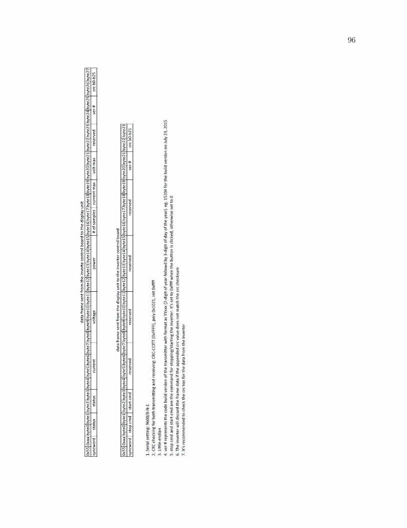
96
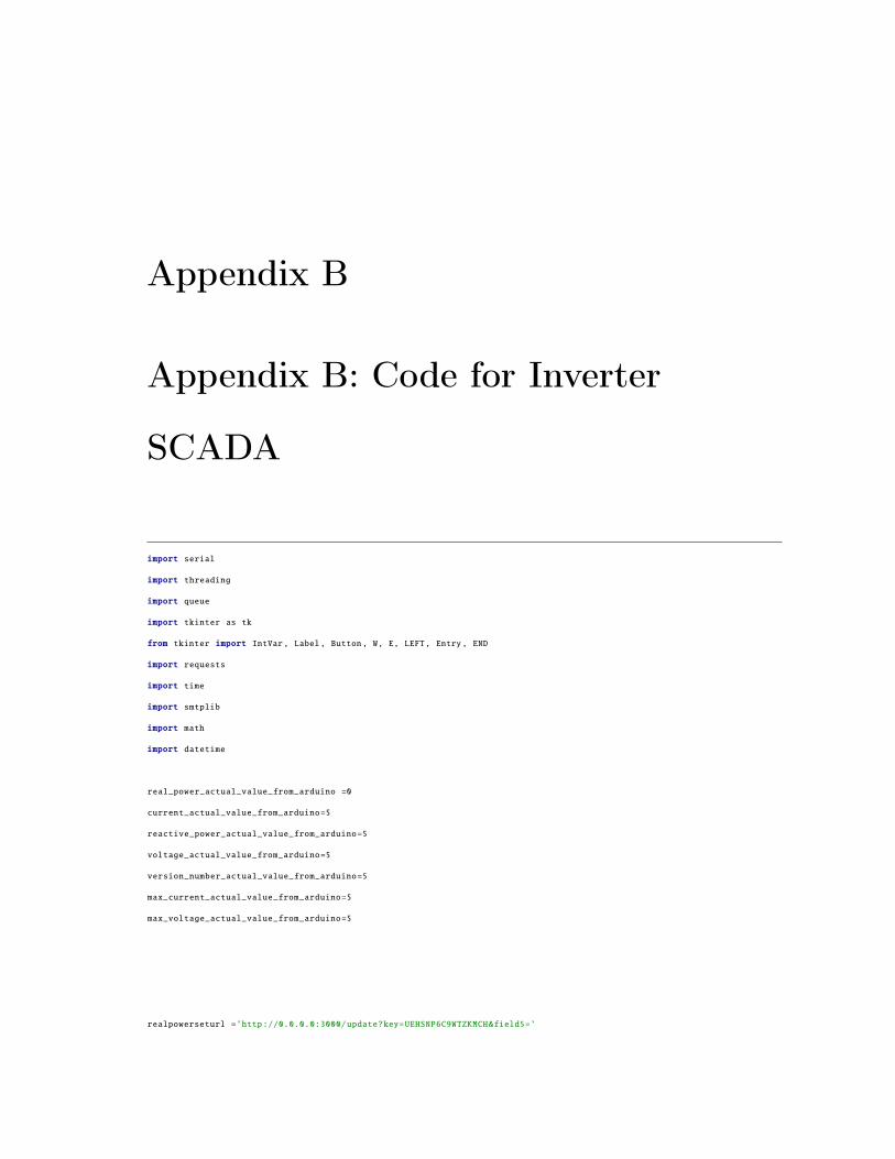
Appendix B
Appendix B: Code for Inverter
SCADA
import serial
import threading
import queue
import tkinter as tk
from tkinter import IntVar, Label, Button, W, E, LEFT, Entry, END
import requests
import time
import smtplib
import math
import datetime
real_power_actual_value_from_arduino =0
current_actual_value_from_arduino=5
reactive_power_actual_value_from_arduino=5
voltage_actual_value_from_arduino=5
version_number_actual_value_from_arduino=5
max_current_actual_value_from_arduino=5
max_voltage_actual_value_from_arduino=5
realpowerseturl =’http://0.0.0.0:3000/update?key=UEHSNP6C9WTZKMCH&field5=’
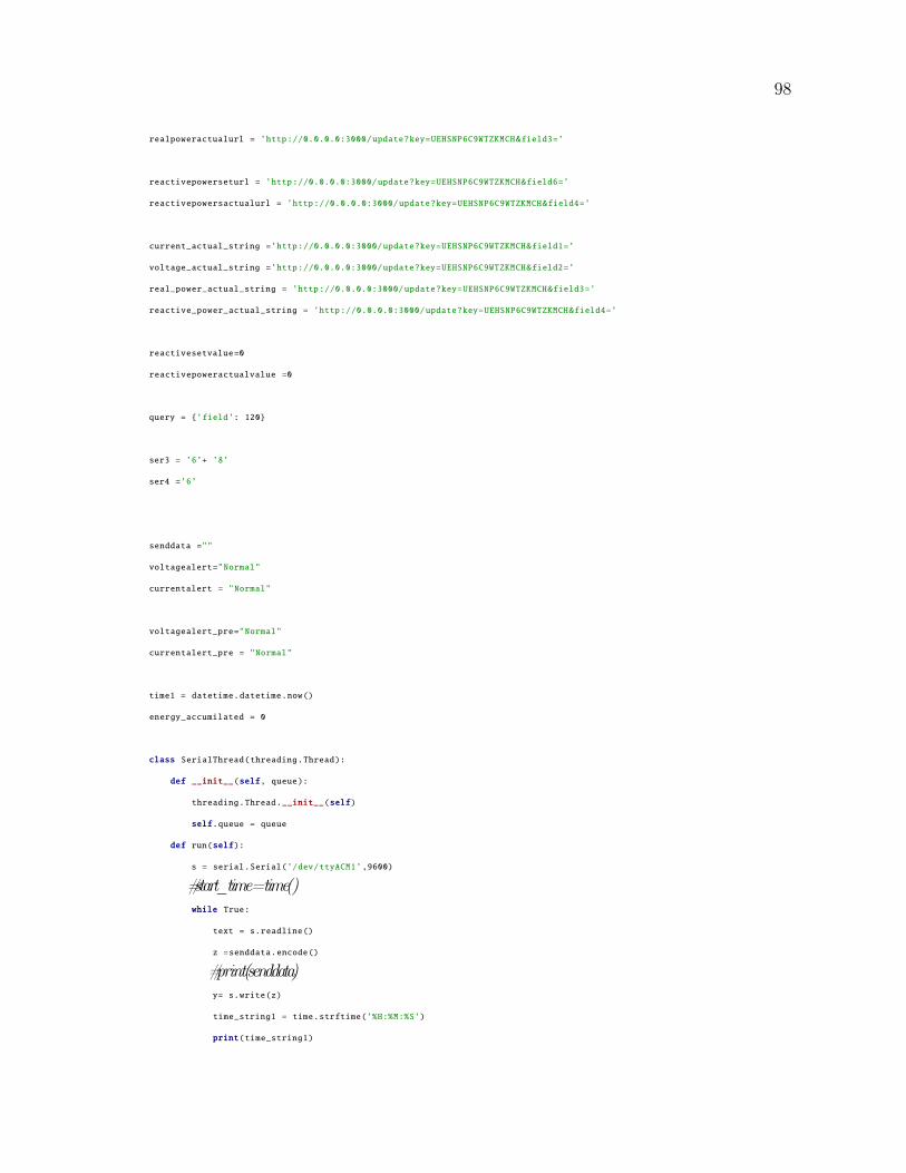
98
realpoweractualurl = ’http://0.0.0.0:3000/update?key=UEHSNP6C9WTZKMCH&field3=’
reactivepowerseturl = ’http://0.0.0.0:3000/update?key=UEHSNP6C9WTZKMCH&field6=’
reactivepowersactualurl = ’http://0.0.0.0:3000/update?key=UEHSNP6C9WTZKMCH&field4=’
current_actual_string =’http://0.0.0.0:3000/update?key=UEHSNP6C9WTZKMCH&field1=’
voltage_actual_string =’http://0.0.0.0:3000/update?key=UEHSNP6C9WTZKMCH&field2=’
real_power_actual_string = ’http://0.0.0.0:3000/update?key=UEHSNP6C9WTZKMCH&field3=’
reactive_power_actual_string = ’http://0.0.0.0:3000/update?key=UEHSNP6C9WTZKMCH&field4=’
reactivesetvalue=0
reactivepoweractualvalue =0
query = {’field’: 120}
ser3 = ’6’+ ’8’
ser4 =’6’
senddata =""
voltagealert="Normal"
currentalert = "Normal"
voltagealert_pre="Normal"
currentalert_pre = "Normal"
time1 = datetime.datetime.now()
energy_accumilated = 0
class SerialThread(threading.Thread):
def __init__(self, queue):
threading.Thread.__init__(self)
self.queue = queue
def run(self):
s = serial.Serial(’/dev/ttyACM1’,9600)
#start_time=time()while True:
text = s.readline()
z =senddata.encode()
#print(senddata)y= s.write(z)
time_string1 = time.strftime(’%H:%M:%S’)
print(time_string1)
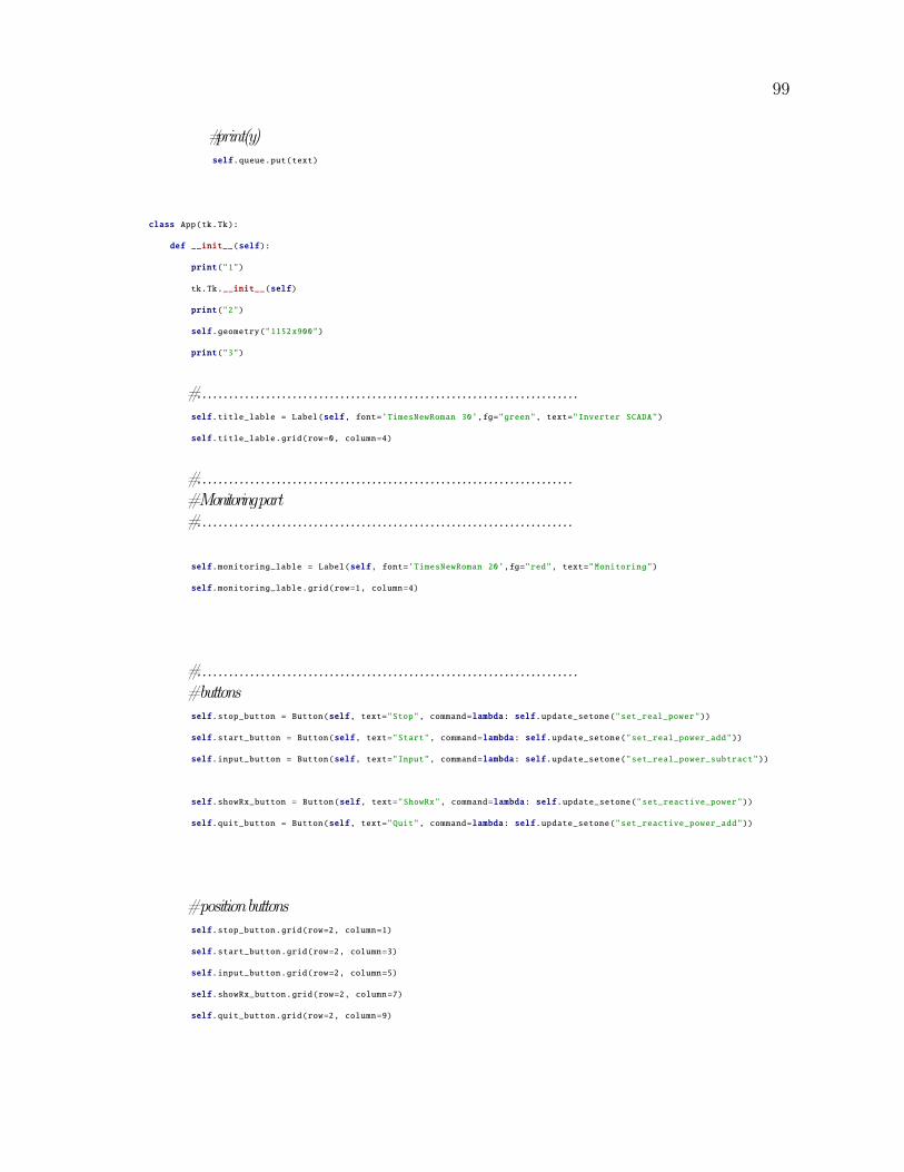
99
#print(y)self.queue.put(text)
class App(tk.Tk):
def __init__(self):
print("1")
tk.Tk.__init__(self)
print("2")
self.geometry("1152x900")
print("3")
#........................................................................self.title_lable = Label(self, font=’TimesNewRoman 30’,fg="green", text="Inverter SCADA")
self.title_lable.grid(row=0, column=4)
#.......................................................................#Monitoringpart#.......................................................................
self.monitoring_lable = Label(self, font=’TimesNewRoman 20’,fg="red", text="Monitoring")
self.monitoring_lable.grid(row=1, column=4)
#........................................................................#buttonsself.stop_button = Button(self, text="Stop", command=lambda: self.update_setone("set_real_power"))
self.start_button = Button(self, text="Start", command=lambda: self.update_setone("set_real_power_add"))
self.input_button = Button(self, text="Input", command=lambda: self.update_setone("set_real_power_subtract"))
self.showRx_button = Button(self, text="ShowRx", command=lambda: self.update_setone("set_reactive_power"))
self.quit_button = Button(self, text="Quit", command=lambda: self.update_setone("set_reactive_power_add"))
#positionbuttonsself.stop_button.grid(row=2, column=1)
self.start_button.grid(row=2, column=3)
self.input_button.grid(row=2, column=5)
self.showRx_button.grid(row=2, column=7)
self.quit_button.grid(row=2, column=9)
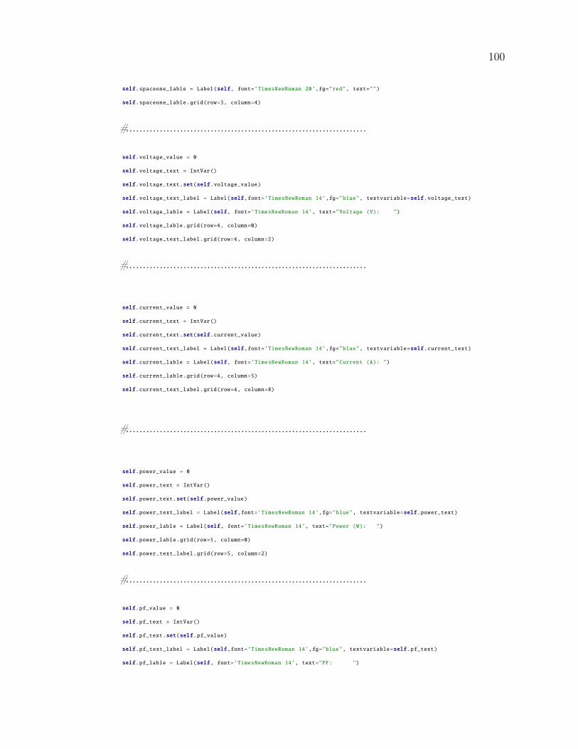
100
self.spaceone_lable = Label(self, font=’TimesNewRoman 20’,fg="red", text="")
self.spaceone_lable.grid(row=3, column=4)
#.......................................................................
self.voltage_value = 0
self.voltage_text = IntVar()
self.voltage_text.set(self.voltage_value)
self.voltage_text_label = Label(self,font=’TimesNewRoman 14’,fg="blue", textvariable=self.voltage_text)
self.voltage_lable = Label(self, font=’TimesNewRoman 14’, text="Voltage (V): ")
self.voltage_lable.grid(row=4, column=0)
self.voltage_text_label.grid(row=4, column=2)
#.......................................................................
self.current_value = 0
self.current_text = IntVar()
self.current_text.set(self.current_value)
self.current_text_label = Label(self,font=’TimesNewRoman 14’,fg="blue", textvariable=self.current_text)
self.current_lable = Label(self, font=’TimesNewRoman 14’, text="Current (A): ")
self.current_lable.grid(row=4, column=5)
self.current_text_label.grid(row=4, column=8)
#.......................................................................
self.power_value = 0
self.power_text = IntVar()
self.power_text.set(self.power_value)
self.power_text_label = Label(self,font=’TimesNewRoman 14’,fg="blue", textvariable=self.power_text)
self.power_lable = Label(self, font=’TimesNewRoman 14’, text="Power (W): ")
self.power_lable.grid(row=5, column=0)
self.power_text_label.grid(row=5, column=2)
#.......................................................................
self.pf_value = 0
self.pf_text = IntVar()
self.pf_text.set(self.pf_value)
self.pf_text_label = Label(self,font=’TimesNewRoman 14’,fg="blue", textvariable=self.pf_text)
self.pf_lable = Label(self, font=’TimesNewRoman 14’, text="PF: ")

101
self.pf_lable.grid(row=5, column=5)
self.pf_text_label.grid(row=5, column=8)
#.......................................................................
self.status_value = 0
self.status_text = IntVar()
self.status_text.set(self.status_value)
self.status_text_label = Label(self,font=’TimesNewRoman 14’,fg="blue", textvariable=self.status_text)
self.status_lable = Label(self, font=’TimesNewRoman 14’, text="Status: ")
self.status_lable.grid(row=6, column=0)
self.status_text_label.grid(row=6, column=2)
#.......................................................................
self.totlakwh_value = 0
self.totlakwh_text = IntVar()
self.totlakwh_text.set(self.totlakwh_value)
self.totlakwh_text_label = Label(self,font=’TimesNewRoman 14’,fg="blue", textvariable=self.totlakwh_text)
self.totlakwh_lable = Label(self, font=’TimesNewRoman 14’, text="Total kwh: ")
self.totlakwh_lable.grid(row=6, column=5)
self.totlakwh_text_label.grid(row=6, column=8)
#.......................................................................#controllingpart#.......................................................................
self.reactive_power_lable = Label(self, font=’TimesNewRoman 20’,fg="red", text="")
self.reactive_power_lable.grid(row=12, column=4)
self.reactive_power_lable = Label(self, font=’TimesNewRoman 20’,fg="red", text="Controlling")
self.reactive_power_lable.grid(row=13, column=4)
#........................................................................
self.reactive_power_lable = Label(self, font=’TimesNewRoman 14’,fg="black", text="Set Value")
self.reactive_power_lable.grid(row=15, column=2)
#........................................................................
self.reactive_power_set_value = 0
self.reactive_power_set_value_text = IntVar()
self.reactive_power_set_value_text.set(self.reactive_power_set_value)
self.reactive_power_set_value_text_label = Label(self,font=’TimesNewRoman 14’,fg="blue", textvariable=self.reactive_power_set_value_text)
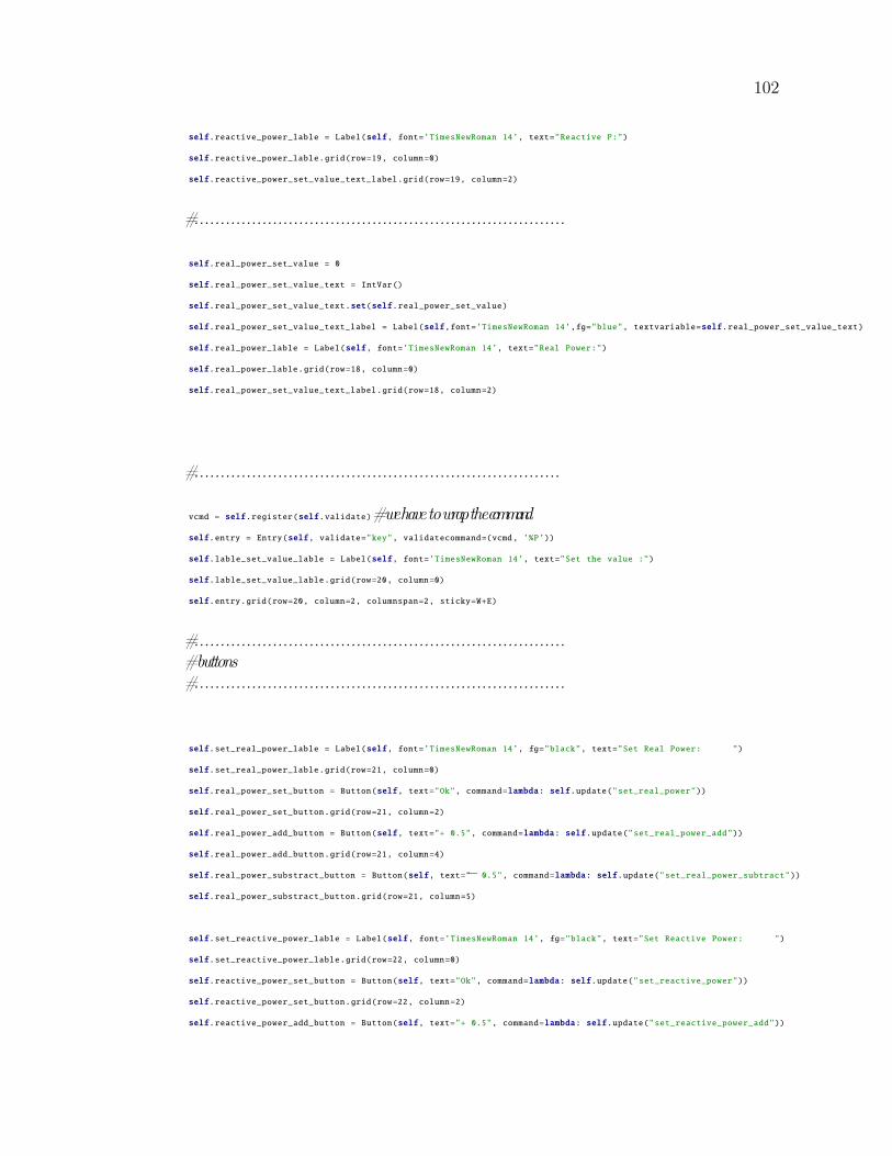
102
self.reactive_power_lable = Label(self, font=’TimesNewRoman 14’, text="Reactive P:")
self.reactive_power_lable.grid(row=19, column=0)
self.reactive_power_set_value_text_label.grid(row=19, column=2)
#.......................................................................
self.real_power_set_value = 0
self.real_power_set_value_text = IntVar()
self.real_power_set_value_text.set(self.real_power_set_value)
self.real_power_set_value_text_label = Label(self,font=’TimesNewRoman 14’,fg="blue", textvariable=self.real_power_set_value_text)
self.real_power_lable = Label(self, font=’TimesNewRoman 14’, text="Real Power:")
self.real_power_lable.grid(row=18, column=0)
self.real_power_set_value_text_label.grid(row=18, column=2)
#......................................................................
vcmd = self.register(self.validate)#wehavetowrapthecommandself.entry = Entry(self, validate="key", validatecommand=(vcmd, ’%P’))
self.lable_set_value_lable = Label(self, font=’TimesNewRoman 14’, text="Set the value :")
self.lable_set_value_lable.grid(row=20, column=0)
self.entry.grid(row=20, column=2, columnspan=2, sticky=W+E)
#.......................................................................#buttons#.......................................................................
self.set_real_power_lable = Label(self, font=’TimesNewRoman 14’, fg="black", text="Set Real Power: ")
self.set_real_power_lable.grid(row=21, column=0)
self.real_power_set_button = Button(self, text="Ok", command=lambda: self.update("set_real_power"))
self.real_power_set_button.grid(row=21, column=2)
self.real_power_add_button = Button(self, text="+ 0.5", command=lambda: self.update("set_real_power_add"))
self.real_power_add_button.grid(row=21, column=4)
self.real_power_substract_button = Button(self, text="− 0.5", command=lambda: self.update("set_real_power_subtract"))
self.real_power_substract_button.grid(row=21, column=5)
self.set_reactive_power_lable = Label(self, font=’TimesNewRoman 14’, fg="black", text="Set Reactive Power: ")
self.set_reactive_power_lable.grid(row=22, column=0)
self.reactive_power_set_button = Button(self, text="Ok", command=lambda: self.update("set_reactive_power"))
self.reactive_power_set_button.grid(row=22, column=2)
self.reactive_power_add_button = Button(self, text="+ 0.5", command=lambda: self.update("set_reactive_power_add"))
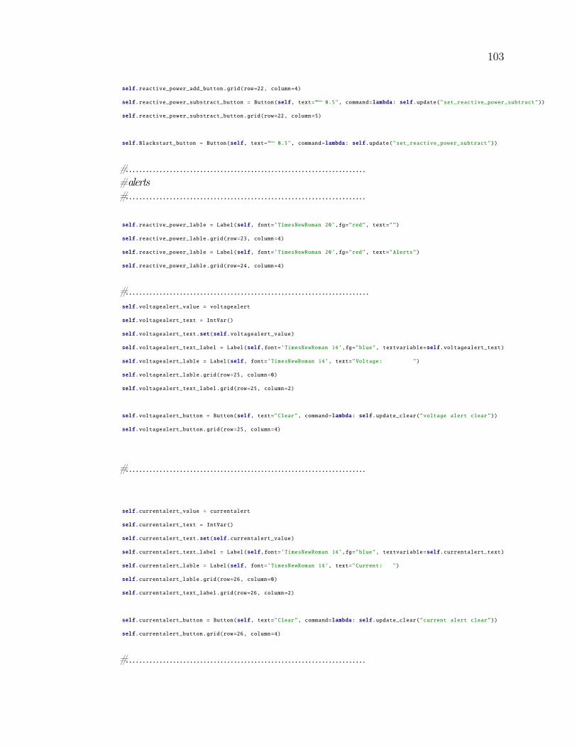
103
self.reactive_power_add_button.grid(row=22, column=4)
self.reactive_power_substract_button = Button(self, text="− 0.5", command=lambda: self.update("set_reactive_power_subtract"))
self.reactive_power_substract_button.grid(row=22, column=5)
self.Blackstart_button = Button(self, text="− 0.5", command=lambda: self.update("set_reactive_power_subtract"))
#.......................................................................#alerts#.......................................................................
self.reactive_power_lable = Label(self, font=’TimesNewRoman 20’,fg="red", text="")
self.reactive_power_lable.grid(row=23, column=4)
self.reactive_power_lable = Label(self, font=’TimesNewRoman 20’,fg="red", text="Alerts")
self.reactive_power_lable.grid(row=24, column=4)
#........................................................................self.voltagealert_value = voltagealert
self.voltagealert_text = IntVar()
self.voltagealert_text.set(self.voltagealert_value)
self.voltagealert_text_label = Label(self,font=’TimesNewRoman 14’,fg="blue", textvariable=self.voltagealert_text)
self.voltagealert_lable = Label(self, font=’TimesNewRoman 14’, text="Voltage: ")
self.voltagealert_lable.grid(row=25, column=0)
self.voltagealert_text_label.grid(row=25, column=2)
self.voltagealert_button = Button(self, text="Clear", command=lambda: self.update_clear("voltage alert clear"))
self.voltagealert_button.grid(row=25, column=4)
#.......................................................................
self.currentalert_value = currentalert
self.currentalert_text = IntVar()
self.currentalert_text.set(self.currentalert_value)
self.currentalert_text_label = Label(self,font=’TimesNewRoman 14’,fg="blue", textvariable=self.currentalert_text)
self.currentalert_lable = Label(self, font=’TimesNewRoman 14’, text="Current: ")
self.currentalert_lable.grid(row=26, column=0)
self.currentalert_text_label.grid(row=26, column=2)
self.currentalert_button = Button(self, text="Clear", command=lambda: self.update_clear("current alert clear"))
self.currentalert_button.grid(row=26, column=4)
#.......................................................................
104
#details of theinverter#.......................................................................
self.version_value = 0
self.version_text = IntVar()
self.version_text.set(self.version_value)
self.version_text_label = Label(self,font=’TimesNewRoman 10’,fg="purple", textvariable=self.version_text)
self.version_lable = Label(self, font=’TimesNewRoman 10’, fg="purple", text="Inverter Version: ")
self.version_lable.grid(row=35, column=0)
self.version_text_label.grid(row=35, column=1)
#........................................................................
self.time_value = 0
self.time_text = IntVar()
self.time_text.set(self.time_value)
self.time_text_label = Label(self,font=’TimesNewRoman 10’,fg="purple", textvariable=self.time_text)
self.time_lable = Label(self, font=’TimesNewRoman 10’, fg="purple", text="Time: ")
self.time_lable.grid(row=35, column=3)
self.time_text_label.grid(row=35, column=4)
#........................................................................
print("7")
self.queue = queue.Queue()
print("8")
thread = SerialThread(self.queue)
print("9")
thread.start()
print("10")
self.process_serial()
print("11")
def update(self, method):
if not self.entered_number ==0:
if method == "set_real_power":
self.real_power_set_value = self.entered_number
elif method == "set_reactive_power":
self.reactive_power_set_value = self.entered_number
elif method == "set_real_power_add":
self.real_power_set_value+=0.5
elif method == "set_real_power_subtract":
105
self.real_power_set_value−=0.5elif method == "set_reactive_power_add":
self.reactive_power_set_value+=0.5
elif method == "set_reactive_power_subtract":
self.reactive_power_set_value−=0.5
self.real_power_set_value_text.set(self.real_power_set_value)
self.reactive_power_set_value_text.set(self.reactive_power_set_value)
ser6 = str(self.real_power_set_value)
url = realpowerseturl+ser6
r = requests.post(url, data=query)
print (r.text)
ser7 = str(self.reactive_power_set_value)
url2 = reactivepowerseturl +ser7
s = requests.post(url2, data=query)
print (s.text)
self.entry.delete(0, END)
def update_setone(self, method):
print(method)
def update_email(self, method):
print(method)
server = smtplib.SMTP(’smtp.gmail.com’, 587)
server.starttls()
server.login("[email protected]", "Lab1234%")
msg = method
server.sendmail("[email protected]", "[email protected]", msg)
server.quit()
def update_clear(self, method):
print(method)
global voltagealert
106
global currentalert
global voltagealert_pre
global currentalert_pre
if method == "voltage alert clear":
voltagealert="Normal"
self.voltagealert_text.set(voltagealert)
voltagealert_pre =voltagealert
if method == "current alert clear":
currentalert = "Normal"
self.currentalert_text.set(currentalert)
currentalert_pre =currentalert
def validate(self, new_text):
if not new_text:#the field is beingclearedself.entered_number= 0
return True
try:
self.entered_number = int(new_text)
return True
except ValueError:
return False
def process_serial(self):
while self.queue.qsize():
try:
x = self.queue.get()
ser1 =x.upper()
#ser2=list(ser1)print (ser1)
if(chr(ser1[0])==’5’):
if len(ser1)>55:
ser_1 = chr(ser1[0])+chr(ser1[1])
ser_2 = chr(ser1[2])+chr(ser1[3])
ser_byt0 = chr(ser1[4])+chr(ser1[5])
ser_byt1 = chr(ser1[6])+chr(ser1[7])
ser_byt2 = chr(ser1[8])+chr(ser1[9])
107
ser_byt3 = chr(ser1[10])+chr(ser1[11])
ser_byt4 = chr(ser1[12])+chr(ser1[13])
ser_byt5 = chr(ser1[14])+chr(ser1[15])
ser_byt6 = chr(ser1[16])+chr(ser1[17])
ser_byt7 = chr(ser1[18])+chr(ser1[19])
ser_byt8 = chr(ser1[20])+chr(ser1[21])
ser_byt9 = chr(ser1[22])+chr(ser1[23])
ser_byt10 = chr(ser1[24])+chr(ser1[25])
ser_byt11 = chr(ser1[26])+chr(ser1[27])
ser_byt12 = chr(ser1[28])+chr(ser1[29])
ser_byt13 = chr(ser1[30])+chr(ser1[31])
ser_byt14 = chr(ser1[32])+chr(ser1[33])
ser_byt15 = chr(ser1[34])+chr(ser1[35])
ser_byt16 = chr(ser1[36])+chr(ser1[37])
ser_byt17 = chr(ser1[38])+chr(ser1[39])
ser_byt18 = chr(ser1[40])+chr(ser1[41])
ser_byt19 = chr(ser1[42])+chr(ser1[43])
ser_byt20 = chr(ser1[44])+chr(ser1[45])
ser_byt21 = chr(ser1[46])+chr(ser1[47])
ser_byt22 = chr(ser1[48])+chr(ser1[49])
ser_byt23 = chr(ser1[50])+chr(ser1[51])
ser_byt24 = chr(ser1[52])+chr(ser1[53])
ser_byt25 = chr(ser1[54])+chr(ser1[55])
number_of_samples=ser_byt17+ser_byt16
number_of_samples_dec= int(number_of_samples , 16)
max_current =ser_byt19+ser_byt18
max_current_dec =int(max_current , 16)
max_voltage = ser_byt21+ser_byt20
max_voltage_dec = int(max_voltage , 16)
print (ser1)
real_current = ser_byt7+ser_byt6+ser_byt5+ser_byt4
real_current_dec1 = int(real_current ,16)
sqrt_for_max_C = math.sqrt(real_current_dec1/number_of_samples_dec)∗max_current_decreal_current_dec2 = sqrt_for_max_C/4096
108
real_current_dec = round(real_current_dec2 ,2)
ser_real_current = str(real_current_dec)
url_real_current = current_actual_string +ser_real_current
s_real_current = requests.post(url_real_current , data=query)
print (s_real_current.text)
self.current_text.set(ser_real_current)#updateongui
global voltagealert
global currentalert
global voltagealert_pre
global currentalert_pre
#set alert if current is greaterthan300if real_current_dec >300:
currentalert="High"
if currentalert_pre =="Normal":
self.currentalert_text.set(currentalert)#updateonguicurrentalert_pre="High"
self.update_email("Your inverter current is high")
print("current is high")
real_voltage = ser_byt11+ser_byt10+ser_byt9+ser_byt8
real_voltage_dec1= int(real_voltage ,16)
sqrt_for_max_V = math.sqrt(real_voltage_dec1/number_of_samples_dec)∗max_voltage_decreal_voltage_dec2 = sqrt_for_max_V/4096
real_voltage_dec = round(real_voltage_dec2 ,2)
ser_real_voltage = str(real_voltage_dec)
url_real_voltage = voltage_actual_string +ser_real_voltage
s_real_voltage = requests.post(url_real_voltage , data=query)
print (s_real_voltage.text)
self.voltage_text.set(ser_real_voltage)#updateongui
if real_voltage_dec >250:
voltagealert="High"
if voltagealert_pre =="Normal":
self.voltagealert_text.set(voltagealert)#updateonguivoltagealert_pre="High"
109
self.update_email("Your inverter voltage is high")
print("voltage is high")
real_power_actual_value = ser_byt15+ser_byt14+ser_byt13+ser_byt12
real_power_actual_value_dec1= int(real_power_actual_value , 16)
#real_power_actual_value_dec2=(real_power_actual_value_dec1∗max_voltage_dec∗max_current_dec)/(number_of_samples_dec)#16777216real_power_actual_value_dec2 = (real_power_actual_value_dec1∗max_voltage_dec∗max_current_dec)/(number_of_samples_dec∗16777216)real_power_actual_value_dec = round(real_power_actual_value_dec2 ,2)
ser_real_power_power = str(real_power_actual_value_dec)
real_power_actual_value_from_arduino = ser_real_power_power
#real_power_actual_value_from_arduino=10url_real_power_actual = real_power_actual_string + ser_real_power_power
s_real_power_actual = requests.post(url_real_power_actual , data=query)
print (s_real_power_actual.text)
ser_real_power_power = str(real_power_actual_value_dec)
self.power_text.set(ser_real_power_power)#updateongui
apperentpower= real_voltage_dec∗real_current_decpf = real_power_actual_value_dec/apperentpower
self.pf_text.set(str(pf))#updateongui
version_number =ser_byt25+ser_byt24
version_number_dec = int(version_number , 16)
self.version_text.set(str(version_number_dec))#updateongui
time2 = datetime.datetime.now()
elapsedTime = time2− time1
print(elapsedTime.total_seconds())
duration = elapsedTime.total_seconds()
time1 = datetime.datetime.now()
energy_acc = real_power_actual_value_dec∗duration/3600000global energy_accumilated
110
energy_accumilated = energy_accumilated + energy_acc
self.totlakwh_text.set(str(energy_accumilated))
print (real_current_dec)
print (real_voltage_dec)
print (real_power_actual_value)
print (number_of_samples_dec)
print (max_voltage_dec)
print (max_current_dec)
print (version_number_dec)
time_string = time.strftime(’%H:%M:%S’)
self.time_text.set(time_string)#updateongui
global time1
except queue.Empty:
pass
self.after(100, self.process_serial)
app = App()
app.mainloop()