action.net scada action.net training · the ssc is popularly called hmi or scada scada (supervisory...
TRANSCRIPT

SCLN 212, Bloco D, Sala 101
Brasília – DF | CEP: 70.865-540
+55 61 3340-8486
[email protected] www.spinegenhria.com.br
Action.NET Scada
Action.Net – Training
Version an-2014.2.50
Training Course
0070.01 February 2017
SCLN 212, Bloco D, Sala 101
Brasília – DF | CEP: 70.865-540
+55 61 3340-8486
[email protected] www.spinegenhria.com.br
Summary
Introduction The Course ..................................................................................................................................................... 6
Structuring of the Tutorial ............................................................................................................................................ 6
Course Evaluation ............................................................................................................................................................ 8
References ......................................................................................................................................................................... 8
Terminology ....................................................................................................................................................................... 8
Used Symbols ................................................................................................................................................................... 8
Technical Support ............................................................................................................................................................ 9
Revision of Tutorial ......................................................................................................................................................... 9
Spin Course ........................................................................................................................................................................ 9
1. Action˳NET: Technical Characteristics ..................................................................................................................... 10
Supervisory Systems .................................................................................................................................................... 10
Product Description ....................................................................................................................................................... 10
Action˳NET Family of Products ................................................................................................................................. 11
General Characteristics of the Product .................................................................................................................... 11
Innovative Features of the Product .......................................................................................................................... 12
Real-time Database ................................................................................................................................................. 12
˳NET Languages and Scripts ................................................................................................................................. 13
Alarms and Security ................................................................................................................................................. 13
Trend and Historians ................................................................................................................................................ 13
DataSet ........................................................................................................................................................................ 14
Reports ........................................................................................................................................................................ 14
Client Screens ............................................................................................................................................................ 14
Runtime Objects ........................................................................................................................................................ 15
Module Isolation ........................................................................................................................................................ 15
Runtime Tools and Diagnostics ............................................................................................................................ 15
Deployment and Testing of Project ..................................................................................................................... 15
Installation ...................................................................................................................................................................... 15
Exercise 1-1: Planning Supervision System ...................................................................................................... 16
2. Action˳NET: Operational Characteristics ................................................................................................................. 17
User Interface (UI) Action.NET ................................................................................................................................... 17
Starting Action˳NET ................................................................................................................................................. 17

SCLN 212, Bloco D, Sala 101
Brasília – DF | CEP: 70.865-540
+55 61 3340-8486
[email protected] www.spinegenhria.com.br
Project Management ................................................................................................................................................ 17
Defining the location of the project ..................................................................................................................... 17
Select Demo Project ................................................................................................................................................ 18
Localization Tools..................................................................................................................................................... 18
Modules Action˳NET ..................................................................................................................................................... 19
Main Menu Items ....................................................................................................................................................... 19
Action˳NET Tools ........................................................................................................................................................... 22
Edit Menu .................................................................................................................................................................... 22
Draw Menu .................................................................................................................................................................. 28
Run Menu..................................................................................................................................................................... 31
Info Menu ..................................................................................................................................................................... 38
Exercise 2-1: Design Supervision System .......................................................................................................... 42
3. Editing the Application ................................................................................................................................................. 44
Issue of Application ....................................................................................................................................................... 44
EDIT>Tags ........................................................................................................................................................................ 45
EDIT>Tags>Objects .................................................................................................................................................. 45
EDIT>Tags>Templates ............................................................................................................................................ 47
EDIT>Tags> Assets .................................................................................................................................................. 48
EDIT>Tags> Historian .............................................................................................................................................. 50
EDIT>Tags> Historian Tables ................................................................................................................................ 51
Exercise 3-1: Process Variables ............................................................................................................................ 51
Edit> Security .................................................................................................................................................................. 52
Edit> Security> Users .............................................................................................................................................. 52
Edit> Security> Permissions .................................................................................................................................. 53
Edit> Security> Polices ............................................................................................................................................ 54
Edit> Devices> ................................................................................................................................................................ 55
Edit>Devices>Channels ........................................................................................................................................... 55
Edit> Devices> Nodes .............................................................................................................................................. 57
Edit> Devices>Points ............................................................................................................................................... 58
Edit> Devices> Access Typer ................................................................................................................................. 59
Edit> Alarms .................................................................................................................................................................... 60
Edit> Alarms> Groups .............................................................................................................................................. 60
Edit> Alarms> Items................................................................................................................................................. 62
Edit>Datasets ................................................................................................................................................................. 64

SCLN 212, Bloco D, Sala 101
Brasília – DF | CEP: 70.865-540
+55 61 3340-8486
[email protected] www.spinegenhria.com.br
Edit> Datasets> DBs ................................................................................................................................................ 64
Edit> Datasets> Tables ........................................................................................................................................... 65
Edit> Datasets> Queries ......................................................................................................................................... 66
Edit> Scripts .................................................................................................................................................................... 66
Edit> Scripts >Tasks ................................................................................................................................................ 66
Edit> Scripts Classes ............................................................................................................................................... 67
Edit> Scripts> Code Editor...................................................................................................................................... 68
Edit> Scripts> Expressions ..................................................................................................................................... 70
Edit > Displays ................................................................................................................................................................ 72
Edit > Displays > Displays ...................................................................................................................................... 72
Edit > Displays > Layouts ....................................................................................................................................... 74
Edit > Displays > Resources ................................................................................................................................... 76
Exercise 3-3: Editing Supervision System .......................................................................................................... 77
4. Design the Application .................................................................................................................................................. 78
Design of the Application. ........................................................................................................................................... 78
Draw > Drawing .............................................................................................................................................................. 78
Editing Procedure ...................................................................................................................................................... 78
Overview of the Vertical Toolbar .......................................................................................................................... 78
Horizontal toolbar ..................................................................................................................................................... 80
Draw > CodeBehind .................................................................................................................................................. 81
Draw > Symbol ........................................................................................................................................................... 82
Exercise 4-1: Design of the Supervisory System ............................................................................................. 85
5. Running the Application ............................................................................................................................................... 86
Application Execution ................................................................................................................................................... 86
Run > Build ....................................................................................................................................................................... 86
Run > Build > Messages .......................................................................................................................................... 86
Run > Build > History ............................................................................................................................................... 87
Run > Build > References ........................................................................................................................................ 88
Run > Test ........................................................................................................................................................................ 88
Run > Startup .................................................................................................................................................................. 89
Run > Publish .................................................................................................................................................................. 90
Run > UseCount .............................................................................................................................................................. 91
Run > Dictionaries .......................................................................................................................................................... 91
Run > Dictionaries > Localization ......................................................................................................................... 92

SCLN 212, Bloco D, Sala 101
Brasília – DF | CEP: 70.865-540
+55 61 3340-8486
[email protected] www.spinegenhria.com.br
Run > Dictionaries > EnumarationSets ............................................................................................................... 93
Run > Dictionaries > Categories ............................................................................................................................ 93
Run > Extensions ........................................................................................................................................................... 94
Exercise 5-1: Implementation of the System of Supervision........................................................................ 95
6. Application Information ................................................................................................................................................ 96
Project Information’s .................................................................................................................................................... 96
Info> Project> Version ............................................................................................................................................. 96
Info> Project> Settings ............................................................................................................................................ 97
Info> Project> Redundancy .................................................................................................................................... 98
Track Project Changes .................................................................................................................................................. 99
Notes Shared between developers .......................................................................................................................... 99
License Information .....................................................................................................................................................100

6
Introduction The Course
This course is designed to teach the use of Spin Action˳NET - the ultimate solution for monitoring
and data acquisition systems and control-exploring basic features, as well as data acquisition
features, graphical interface, reports, access to external databases and scripts so that the
student can specify and configure operator interfaces for applications that require graphics
capabilities differentiated.
The objectives of this course are:
To make known the basic functionalities of Action˳NET with regard to typical applications,
models, resources, and communication installation.
Present and use the Action˳NET tool for the development of applications of Human
Machine Interface (HMI) as well as Supervisory Control And Data Acquisition (SCADA),
exploring its main features, such as data acquisition functions, graphical interface,
reports, access to external databases and scripts.
This course is intended for customers of Tatsoft, potential users, technical professionals and
engineers in related areas.
The design of the course is designed to enhance the direct teaching, using that provide integration
between theory and practice and promote capacity building and knowledge management and the
continuous self-development.
Resources associated contain elements of high quality instruction and are sufficiently
comprehensible, attractive and dynamic.
Structuring of the Tutorial
The document also includes considerations for installation, electrical connections and basic
settings. It is divided into chapters on a standardized structure. The structure is laid out below:
Some chapters contain Exercises whose implementation will allow students to consolidate the
concepts covered in the Tutorial, applying them in problem situations. The goal is that students
solve the tasks proposed in a relatively independent mode from the guidelines set by the instructor.
Another learning strategic design of the course is the research on Product Documentation, allowing
students to become familiar with access to a collection of manuals, application notes, technical
characteristics, etc.
Course Overview
The tutorial is divided into chapters, covering the topics listed below:
Chapter 1: Technical Characteristics

7
Topics covered:
Product description
Product features
Innovative Features
Chapter 2: Operational Characteristics
Topics covered:
Starting Action˳NET
Managing Projects
Accessing the Tools
Exercises
Chapter 3: Editing the Application
Topics covered:
Tags
Security and Alarms
Devices, Data Sets, and Scripts
Displays and Reports
Exercises
Chapter 4: Designing the application
Topics covered:
Static Objects
Dynamic Objects
Symbols and Colors
Exercises
Chapter 5: Execution of Application
Topics covered:
Build, Test and Startup
Runtime Features
Project Information
Exercises
Chapter 6: Application Information
Topics covered:
Project Information
Version Information
Runtime Objects
Exercises
Chapter 7: Applications
Topics covered:
References and Applications

8
Targeted Exercises
Scripting Language Quick Reference
Proposed Exercises
Selected Case Study
Evaluation
Closure
Course Evaluation
The continuing assessment is a common practice adopted by the instructor in the course. In this
way, the following evaluation strategies are considered: student development follow-up
(frequency, participation, attitude, interest and knowledge construction) during the course by
technical support and resolution of proposed tasks via self-assessment characterized by
Exercises, research on documentation and applications
References
User manuals and technical characteristics, as well as Tutorials related products obtained in Spin
site http://spinengenharia.com.br/en/.
Terminology
The following expressions can be employed in the text of the Tutorial.
PLC: Programmable Logic Controller - equipment consisting of a CPU, input/output modules and
power supply.
CPU: Central Processing Unit - the main module of PLC, which performs the data processing.
Used Symbols
The symbols used throughout this manual have the following meanings:
a) • This marker indicates a list of items or topics
b) small caps indicate key names, for example, ENTER
c) key1 + key2 is used for keys to be pressed simultaneously. For example, pressing the Ctrl
key and End key simultaneously is indicated as Ctrl + End.
d) Key1, Key2 is used for keys to be pressed sequentially. For example, the message "Type
ALT, F10" means that the Alt key must be pressed and released and then the F10 key
pressed and released.
e) LARGE caps indicate names of files and directories.
f) Italics indicates words and characters that are typed on the keyboard or viewed on the
screen. For example, if you are prompted to enter FACAO, these characters must be typed
exactly as they appear in the manual.
g) BOLD is used for names of commands or options, or to emphasize important parts of the
text.

9
Technical Support
If Action˳NET is already installed, it is advisable to provide the following information before you
contact us:
Product Family and Model.
Serial number of license
In some circumstances it may expedite the
resolution if a copy of the project is made
available for the technical support team
Email: [email protected]
Revision of Tutorial
The reference code, the revision and the date of the present document are indicated on the cover.
The change of the revision could mean changes in the functional specification or improvements in
the same. Following the amendments corresponding to each revision of this:
Spin Course
Spin conducts training courses typically every other month as needed. Likewise, our distribution
channel partners either conduct or host training classes as well. On-site training is an option and
are intended to be in accordance with the requests and needs of customers. The courses, which
deal with the Action˳NET product line, are intended to introduce concepts of industrial automation
and empower participants to develop applications for process control.
Fig. Product Specification

10
1. Action˳NET: Technical Characteristics
Supervisory Systems
The supervision and control system (SCS) is a fundamental part of almost any process automation
system. The SCS came up with the basic function of providing a user-friendly interface (generally
graphics) with the process operators, allowing them to perform the following functions:
Monitor real-time process variables (temperature, pressure, level, amongst others)
Diagnose failures or improper conditions through alarms and events
Diagnose failures or improper conditions through alarms and events;
Adjust process parameters (setpoints)
Send commands to the system.
The SSC is popularly called HMI or SCADA
SCADA (Supervisory Control and Data Acquisition): strictly speaking, a SCADA system is made not
only by the SSC, but also by the instrumentation, PLCs and all communication infrastructure used
in automation and control systems. However, it is common to define the supervisory software as
SCADA. This is usually located in the control room, running on a PC platform. HMI (Human Machine
Interface): is often required for an interface located on the factory floor for the operator to have
local access to process information. These vary from small alphanumeric device interfaces to
colorful interfaces, with membrane or fabric panel touch-screens. It is important to stress that the
supervisory software has no function to perform real-time control, such as a Programmable Logic
Controller (PLC).
Product Description
Spin Action˳NET is the ultimate solution for monitoring and data acquisition systems and control.
Spin's reputation is associated with excellence in automation systems, offering superior
performance, state-of-the-art technology and features such as redundancy, online changes, hot
swap, high connectivity and other advanced features. This vast experience in industrial automation
systems formed the basis for the development of SCADA/HMI software. Spin Action˳NET meets
high performance requirements, expanded connectivity capabilities, graphical user interfaces
extremely rich and powerful and advanced data acquisition mechanisms in real-time. The selection
of drivers embedded in the software, distributed engineering capacity, redundancy, the OPC
support and Add-ons such as support for iPad/Apple iPhone guarantee the user a new and unique
experience with Action˳NET. Created on Microsoft Windows Presentation Foundation (WPF),
Action˳NET technology allows the user to obtain better results with the current graphics cards,
resulting in exceptionally performing applications. Seamless integration of software as a service
with local facilities, for example, allows the Action˳NET offer the convenient concept of Distributed
Engineering, enabling application developers to collaborate simultaneously during development,
using internet browsers.
Spin Action˳NET also includes the standard features found in the product range, such as interaction
with database servers (SQL, PI, Oracle, Sybase, Informix, and others), custom network buses, a
module of event notification and easy-to-use alarm server, a registry and reporting component, a
historian Server Advanced management capabilities of business logic, as well as support for local
and remote clients running on computers, web, tablets and smartphones.
11
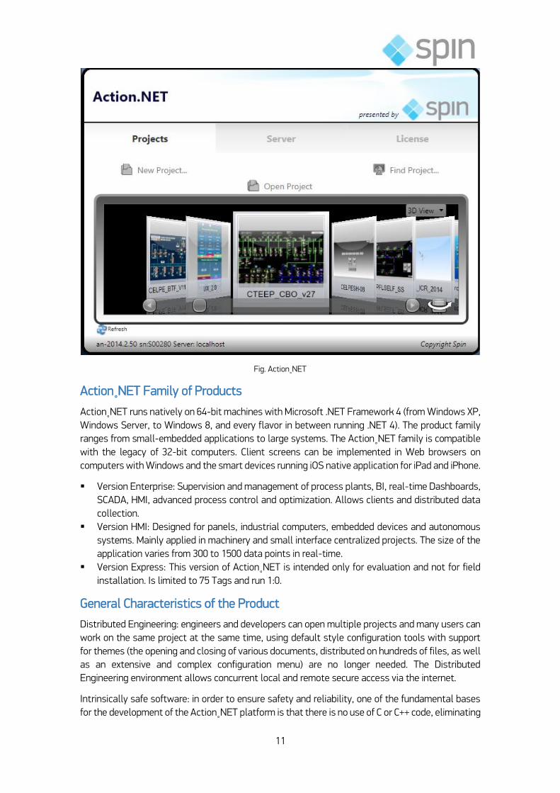
Fig. Action˳NET
Action˳NET Family of Products
Action˳NET runs natively on 64-bit machines with Microsoft .NET Framework 4 (from Windows XP,
Windows Server, to Windows 8, and every flavor in between running .NET 4). The product family
ranges from small-embedded applications to large systems. The Action˳NET family is compatible
with the legacy of 32-bit computers. Client screens can be implemented in Web browsers on
computers with Windows and the smart devices running iOS native application for iPad and iPhone.
Version Enterprise: Supervision and management of process plants, BI, real-time Dashboards,
SCADA, HMI, advanced process control and optimization. Allows clients and distributed data
collection.
Version HMI: Designed for panels, industrial computers, embedded devices and autonomous
systems. Mainly applied in machinery and small interface centralized projects. The size of the
application varies from 300 to 1500 data points in real-time.
Version Express: This version of Action˳NET is intended only for evaluation and not for field
installation. Is limited to 75 Tags and run 1:0.
General Characteristics of the Product
Distributed Engineering: engineers and developers can open multiple projects and many users can
work on the same project at the same time, using default style configuration tools with support
for themes (the opening and closing of various documents, distributed on hundreds of files, as well
as an extensive and complex configuration menu) are no longer needed. The Distributed
Engineering environment allows concurrent local and remote secure access via the internet.
Intrinsically safe software: in order to ensure safety and reliability, one of the fundamental bases
for the development of the Action˳NET platform is that there is no use of C or C++ code, eliminating

12
the risk of problems with pointer and/or memory exceptions. Each task execution and process,
either internally or created to be executed in the context of Action˳NET, is executed in its own
space allocated and protected with internal exception control, isolation of memory, multitasking
and synchronization control in real time. The software development methodology employed with
VBA, VBScript, and mathematics/proprietary logic, where potential problems can only be detected
at run time is eliminated and replaced by compiled .NET languages with complete script validation
before the deployment of runtime with internal protection, which gives higher performance, greater
operational stability and security.
Mechanism Top Chart: charts on Action˳NET are of type Windows Presentation Foundation (WPF)
with full support for XAML. This allows integration with geospatial maps and 3D models. 3D models
can be presented directly, as well as dynamic data-bound with answers associates and behaviors
based on events and values in real-time.
A powerful WPF graphic Editor is included in Action˳NET. Customers depend on XBAP web
(browser-based applications and Silverlight) so that there is no requirement for the installation of
any ActiveX type external component. In addition to the support that allows web pages to be
presented in smartphones, Action˳NET supports graphics and reports from the Apple iPad and
iPhone.
Maintenance capabilities, and advanced diagnostic test: the system allows the exchange of project
versions, allowing the applications in test mode to run side by side on the same server, with
applications in production mode for validation and quality assurance, including the analysis of
usage statistics and reporting PLCU runtime modules and networks provided. Hot-standby options
for internal redundancy, alternative sites of operation and disaster recovery are also incorporated.
Servers and .NET Extensions Incorporated: in addition to the embedded modules for real-time
database, SQL and external ERP connections, server alarms and events, and historian server
reporting, Action˳NET fully accesses the Microsoft .NET Framework, allowing advanced
customization and extensibility, without adding any kind of third party application or external tool.
Action˳NET was designed from a "green field" and was created entirely without using any legacy
code, and is a 100% managed code application that allows users to use and harness the full
potential of Microsoft .NET Framework today, as in the future.
Action˳NET has a configuration interface created entirely from the Microsoft Windows
Presentation Foundation (WPF) Graphics and fully supports software such as the service "SaaS"
(deployment combined with local facilities), allowing users of Action˳NET to access and
collaborate on the development of projects throughout the world with just an internet browser.
Innovative Features of the Product
The Action˳NET supports the following data types in real-time: Digital (Boolean), analog (integer,
Double, and Decimal), text message, data table, counter, timer and date and time variables. In
addition, the user can define their own data types with various levels of inherence, Reference Tags
and three-dimensional arrays.
Real-time Database
The database ensures real-time, without the need for any additional programming, data
synchronization across multiple processes on the server and multiple client stations. A wide range
of built-in properties, such as data quality, time stamp, and State lock value block, enable and
simplify the creation of applications

13
˳NET Languages and Scripts
Action˳NET is a SCADA system that supports the Microsoft ˳NET languages in complete
integration with the Microsoft .NET Framework. The logical design and scripts can be written in C#
or VB.NET and an embedded language converter enables you to dynamically switch the code
created between languages. In the Action˳NET environment, the user can compile, perform the
cross-reference objects and directly access (using Intellisense) ˳ NET classes and objects of design,
including alarms, reporting and communication nodes. The .NET languages provide a more efficient
environment when compared to VBA or VBScript, which are interpreted and not compiled
languages. These technologies add many programming errors that are perceived only when
executing a VBA project or VBScript in real-time, resulting often in consequences and unwanted
results. The managed environment of the Microsoft ˳NET Framework supports locating and
recovering the exceptions, thus providing a highly reliable environment to run the system and
applications.
Alarms and Security
You can set multiple alarm levels for each point or tag and a whole range of behaviors, such as
alarm logging, display, etc. which are pre-defined for ease of configuration. The security system
can set access levels for each screen object. Alarm and security conditions are automatically
replicated in redundant applications. Alarm tools, events and safety provide all the functionality
required to create applications compatible with the FDA-CFR Part 21.
Trend and Historians
Action˳NET allows you to create historian archives in external databases such as Microsoft SQL
Server or Oracle, or even use the Spin embedded SQL database. It allows saving data based on
data change or group triggers and has an exclusive option to time range that prevents logging data
with a time stamp less than a predefined value, allowing the creation of more compact databases.
Access to a server of OSIsoft's PI is also possible.
The time stamp feature can use a value supplied directly from the remote I/O, instead of that of
the computer, ensuring greater accuracy in the event. The organization of the samples allows you
to include or remove Tags to log without losing compatibility with the latest data. A complete trend
chart object is also provided for viewing online and historical data.
Devices and Networks
Action˳NET is provided with an OPC driver for gathering information from remote devices. In
addition to OPC, Action˳NET also supports integrated communication protocol drivers to directly
access protection relays, concentrators, PLCs, remote I/O systems, fieldbus standards, unique and
multiple loops, scanners, barcode readers, RFID devices and digital displays.
The device configuration tool can import OPC server’s databases, text files or CSV. If the device is
compatible, it automatically implements multitasking systems in TCP/IP networks. The address
syntax follows the naming convention of the remote device, making the configuration and
maintenance much easier. In addition, a complete set of performance and diagnostic tools is
included

14
DataSet
The data collection module included in Action˳NET provides an interface for easy real-time data
exchange with external databases, XML, CSV or text files, as well as access to tables and SQL
queries.
For the most popular databases and data sources (Microsoft SQL Server, Oracle, Microsoft Access,
CSV files, PI, Firebird, Informix, and Excel), Action˳NET provides predefined settings that reduce
configuration management to a mouse click. Any database that supports ODBC, ADO.NET or OLE-
DB can also be accessed. A database engine Tatsoft DB SQL embedded is supplied as local
database option for the application.
The data collected via data sets can be mapped dynamically in real time for points/Tags and can
be used in scripts or reports or even presented on screens using a powerful visual data grid object
Reports
Action˳NET supports web services, XML and other data exchange interfaces aiming to provide data
for the external reporting tools. In contrast with other packages, where reports are necessarily
created in another tool, Action˳NET has its own internal Report Editor.
The Report Editor allows the inclusion of dynamic text, graphic symbol and dynamic graphics,
DataSet and query results in a complete and easy-to-use editor. Reports can be saved in HTML,
text or XPS and easily presented in remote clients.
Client Screens
The Action˳NET graphic editor uses WPF technology from Microsoft to enable the creation of rich
user interfaces with real-time mapping of values and Tags of the process: a rich, powerful and
complete set of dynamic animations is also included.
The screens are saved internally by using XAML, which provides resolution independence, isolation
of code and easy extensibility. A library of symbols, where the symbols can also maintain a dynamic
link with the library, speeds up the process of creation of synoptics. All client technologies support
redundant server scenarios.
Three types of remote clients are supported:
Visualizer Clients: runs as a desktop application and allows the locking of Windows task
switcher (keys "CTRL-ALT-DEL" and "ALT-TAB"). This is ideal for operators/intranet users with
security demands;
Smart Clients: uses Smart Client .NET technology from Microsoft and installs on remote clients
with a single click and without administrator requirements. The application is updated
automatically on remote clients, when it is updated on the server. Action˳NET uses the full
potential of remote computer and still retains the advantages of a centralized installation;
XBAP Partial Trust Clients: client screens can be used directly from web browsers without the
need for installation of any software (including ActiveX controls). The partial trust security
ensures that the client displays are run in a completely isolated environment. As with the
Smart Clients, when the application is updated on the server, it is automatically updated on
the clients.

15
Runtime Objects
More advanced than most systems, where it is necessary to create Tags or variables for all the
built-in properties and logic to customize projects, Action˳NET allows applications to directly
access all runtime objects created in the project.
This means that temporary user-created Tags are not required to manage the status of the PLC
nodes, the total number of alarms in a group or of the number of rows in a DataSet. Now you can
access the runtime objects (representing a network node), a group of alarms or data sets and
display the necessary information as well as take action directly through their properties.
Module Isolation
For better performance, security and reliability, the highest CPU consuming modules such as
Scripts, datasets, devices (Communication Drivers), reports and screens, are run in their own
processes or in the area of application in its own thread, regardless of the database server in real-
time.
In addition to the benefits described above, Action˳NET architecture also allows the distribution of
the data acquisition application, or any CPU intensive application on different computers in a
distributed environment, thus providing greater flexibility to implement various redundant
scenarios and consequent simplification of field maintenance.
Runtime Tools and Diagnostics
The Property Watch monitoring tool allows you to check and simulate values in all modules and
objects, as well as start and stop all the modules individually.
The Trace Window tool automatically generates system messages about important events at run
time and can be easily extended to emit specific messages related to script events, data changes
of Tags/points or user actions.
The Module Information tool is a tool for performance and advanced profiling that provides inside
information for the entire runtime environment.
Deployment and Testing of Project
Before you run an application or project, the user can use the exclusive "test mode" which performs
the same in a secure testing environment. In "test mode", there are no commands sent to remote
controllers (only read commands are sent). Alarms and historians save data in temporary files and
external databases in real time are accessed in read-only mode.
After successfully completing the test, the user needs to execute the "StartUp" option to get the
full functionality. When the project or application is ready to be deployed in the field, the user must
use the "publish" feature to configure the redundancy options (if applicable) and to create a copy
of the read-only project for field installation.
Installation
To run the Action˳NET software installation is necessary to perform the download of the
installation file from the site http://spinengenharia.com.br/en/. Then close all programs running on
your PC, double-click the installation file, and then click next.

16
The license agreement screen that appears must be read carefully. If the license terms are
accepted, select the radio button to continue installation. In the next installation screen click Next
to proceed.
During installation, you will see another screen, which should be read carefully. This agreement is
about the Advosol OPC core components. If the license terms are accepted, the check box must be
selected to continue the installation. The next installation screen, click Next to continue.
At this point, the installation of the Advosol OPC core components begins. Please wait while the
necessary files are installed on the PC. This may take several minutes depending on the
configuration of the PC.
Upon completion of the installation of the Advosol OPC core components the installation of the
Action˳NET starts. Please wait while the necessary files are installed on the PC. This may take
several minutes depending on the configuration of the PC.
After the “installation is complete” screen appears, click “Finish” to complete the procedure.
Action˳NET is installed and ready to use. To run the shortcut, click the shortcut "Action˳NET"
created during the installation, on the Start Menu.
Exercise 1-1: Planning Supervision System
Steps X Planning Activities
The steps that make up the planning of a system of supervision can be summarized in the table
shown below.
Check with the instructor and colleagues about these steps versus Activities in the context of
Action˳NET.
17
2. Action˳NET: Operational Characteristics
User Interface (UI) Action.NET
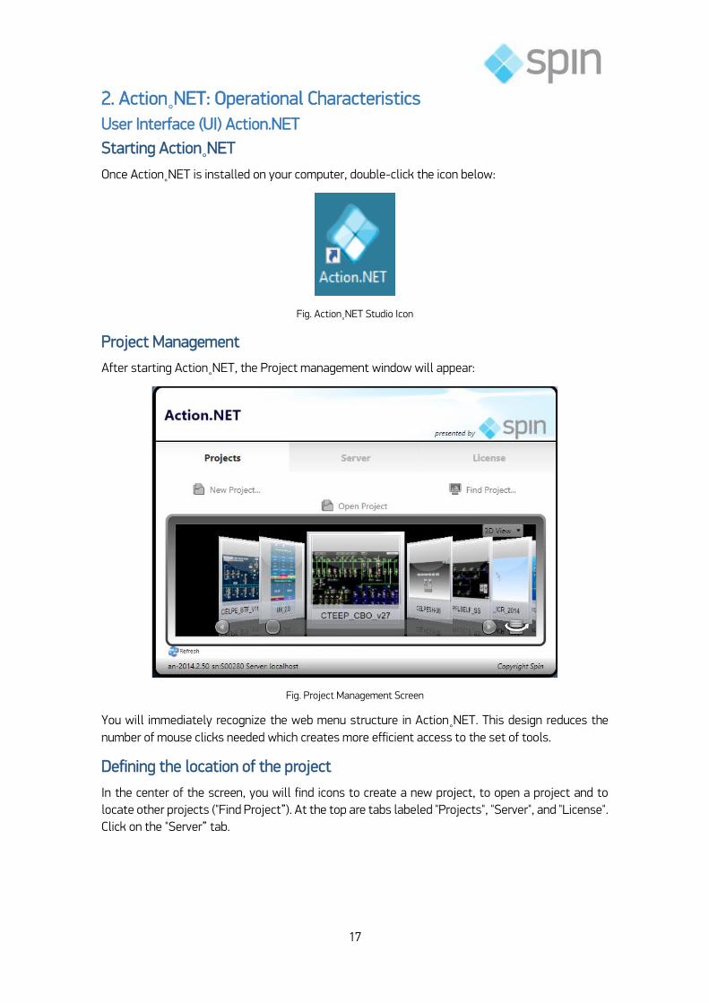
Starting Action˳NET
Once Action˳NET is installed on your computer, double-click the icon below:
Fig. Action˳NET Studio Icon
Project Management
After starting Action˳NET, the Project management window will appear:
Fig. Project Management Screen
You will immediately recognize the web menu structure in Action˳NET. This design reduces the
number of mouse clicks needed which creates more efficient access to the set of tools.
Defining the location of the project
In the center of the screen, you will find icons to create a new project, to open a project and to
locate other projects ("Find Project”). At the top are tabs labeled "Projects", "Server", and "License".
Click on the "Server” tab.

18
Fig. Server Tab
You will see three options: LocalHost, Remote, and Cloud. Click the first to specify whether your
project will run locally, on the second if the project is run from a web server, or if your project is
located on the Spin or your cloud server, and specify the relevant information.
Select Demo Project
From the projects tab in the Project Editor, move the scroll bar, and double-click the Demo project.
This will take you to the project editing tools.
Localization Tools
The configuration UI operates as a front-end web page where you can easily navigate to the forms
and fill them out. The date is automatically saved to the back-end, without having to
open/save/close the menus

19
Fig. Localization tools
Modules Action˳NET
Main Menu Items
Menu Edit
To configure the basic elements of your project from the main menu click on "Edit.
Main Menu
Submenu: the
content of the
submenu changes
when you select
new item from
main menu.
Desktop
Recent itens Desktop guides Quick links

20
Fig. Icons Menu Edit
Draw Menu
To configure dynamic graphical displays click the "Draw" icon from the main menu. The Appearance
attributes dictate the style of the brush to draw the object on the screen, including its color. The
"Fill" option allows you to specify colors, gradients or other objects with which can fill the chart.
Screen settings dictate their attributes. The screens can be configured as PopUps, dialogues or
normal screens. With any graphical object, you can present a variety of colors and patterns,
borders, titles, and more. A special feature is that you can specify a transition animation between
the screens, in the same way as in PowerPoint.
Fig. Draw Menu

21
Run Menu
The Run environment allows access to all parameters of the project. The following functionalities
are included:
Prepare a project to be executed and saved in the build history.
Test the project before you publish it for use on the server.
Specify which diagnostic tools and modules will be used in the execution of the project.
Publish the project to enable your final installation. Updates the revision numbers of the
published project.
Count the number of Tags used in the project. Provide cross-reference to objects in the project.
Customize your project for the use of other languages in the alarm messages and on-screen
text.
Imports/export data from OPC servers, ControlLogix, OSIsoft PI Servers already created, any
configuration table or entire projects.
Fig. Run Menu
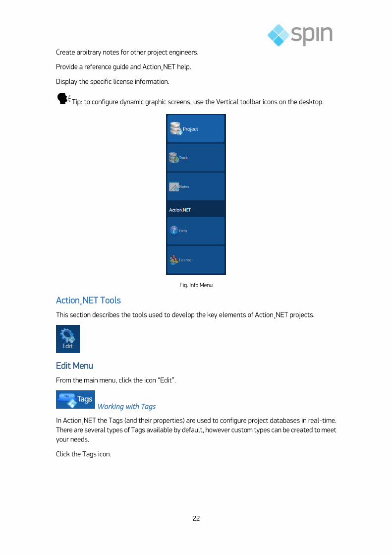
Info Menu
The following features are available in the Info menu:
Provides access to current project details: product version and design, location, local language and
license information.
Locates information related to the release number of the project and changes in the same.
22
Create arbitrary notes for other project engineers.
Provide a reference guide and Action˳NET help.
Display the specific license information.
Tip: to configure dynamic graphic screens, use the Vertical toolbar icons on the desktop.
Fig. Info Menu
Action˳NET Tools
This section describes the tools used to develop the key elements of Action˳NET projects.
Edit Menu
From the main menu, click the icon “Edit”.
Working with Tags
In Action˳NET the Tags (and their properties) are used to configure project databases in real-time.
There are several types of Tags available by default, however custom types can be created to meet
your needs.
Click the Tags icon.

23
Fig. Tags
With the "objects" tab selected click on the top line of the table to define a new Tag. Double-click
any other line to edit an existing Tag.
The type tab is used to create custom Tags, such as PID, for example.
The Historian tab is where you define parameters for data collection Tags.
Security
In Action˳NET, security is used to determine which users will have access to the various project
components. This includes the ability to change values of Tags, opening screens, generate Reports
and other options.
The Ids Administrator levels and guests have embedded meanings. The Administrator is the only
user who can delete or block other users and you can set passwords for the interfaces to databases
(DB). Guest users are used to login anonymous users and do not have passwords assigned to them.
Fig. Security
User sessions can be controlled so that the logout is performed automatically as the inactivity,
duration of the system or both.

24
Alarm conditions online are automatically replicated in redundant applications.
Along with the alarm and event features, Security tools provide the tools needed to create
applications compatible with FDA- CFR 21 Part 11.
Devices
Action˳NET supports embedded communication protocol drivers for direct access to relays, PLCs,
concentrators, etc. OPC is also supported, although in most cases it is not necessary. If you need
an interface with a device with a published protocol, Spin can provide a built-in driver for your
device. A protocol driver toolkit is also available so that you can create your own add-on driver.
Click the Devices icon... The device configuration tool can import OPC servers database, CSV or text
files. If the device is compatible, it automatically will implement a multitasking system in TCP/IP
networks or in serial scenarios. The address syntax follows the Convention of the name of the
remote device, which makes the configuration and maintenance much easier. Included is a
complete set of performance and diagnostic tools.
Fig. Devices
The Channels tab is where you specify the name of the Protocol being used, as well as its
connectivity options. The Nodes tab is where you the address of a device. The Points tab is where
you set the values for acquisition of data from field devices and map them to the values of the
Tags. The Access Types tab allows you to specify whether the device will be Written, read-only or
both, and is where you can create custom Access types.
Alarms
The Action˳NET alarms system provides tremendous flexibility in managing alarms on your system.
You can set multiple alarm levels for each point/tag, plus a wide range of behaviors, such as
logging, recognition, and others, which are designed to simplify the configuration. Alarm conditions

25
are automatically replicated on redundant servers to ensure that there is no loss of alarm in the
case of possible computer failure. Alarm and Event tools are part of the necessary tools to create
applications compatible with the FDA-CFR 21 Part 11.
Click the Alarms icon.
Fig. Alarms
Using alarm Groups you can assign common parameters for alarms, for example, if
acknowledgement should be required for the alarms, or if you want a sound to be emitted. You
have complete control over the colors for various alarm conditions – which makes it possible to
meet corporate standards.
Datasets
The module included in the Action˳NET Dataset provides a user-friendly interface for real-time
data exchange with external database, XML, CSV or text files, as well as access to SQL queries
and tables. For databases and most common data sources (Microsoft SQL Server, Oracle, Microsoft
Access, CSV files, PI, Firebird, Informix, and Excel), Action˳NET provides pre-defined settings that
reduce configuration to a single click of mouse. Any database that supports ODBC, ADO.NET or
OLE-DB can be accessed. A Spin DB SQL embedded Database Engine is also provided as a local
database for your application. Click the Datasets icon.

26
Fig. Datasets
The data collected with the datasets can be dynamically mapped to points/real-time and Tags can
be used in scripts or reports or be presented on screens with the use of a powerful Visual data grid
Object.
Fig. Data Grid Object
The data grid object supports several display themes.
Scripts
Action˳NET supports all Microsoft .NET languages in complete integration with the Microsoft .NET
Framework. Within the Action˳NET framework architecture you can compile, perform cross-
reference with the objects and directly access the .NET classes (using the Intellisense
functionality) and its objects of design, including Alarms, reporting and Communication nodes. Click
the Script icon.
Fig. Scripts

27
The .NET languages provide an environment more powerful when compared to VBA or VBScript,
mainly because they are interpreted and not compiled. In this way many errors can only be
identified when running your project VBA or VBScript in real-time often with bad results and
undesirable consequences. The managed environment of the Microsoft .NET Framework supports
locate and retrieve exceptions, thus providing a highly reliable environment for
applications/systems at runtime. Project Scripts and business logic can be written in C# or VB.NET
and a built-in language converter enables you to replace the code created dynamically between
languages.
Displays
Few products include a fully integrated WPF (Windows Presentation Foundation) graphical editor.
Action˳NET goes beyond this, offering a WPF model, integrated and empowered to provide a
product configuration environment created with WPF and XAML tools. This enables users to exploit
the full potential of video cards available today and also get an excellent experience for application
development speed and efficiency.
Click the Displays icon.
Fig. Displays
Action˳NET is a complete, integrated tool for creating business intelligence applications, real-time
dashboards and advanced graphical data visualization. Embedded objects to data grids, alarms,
trends, XPS reports Viewer provide a "quick-start" for the development of the project.
Reports
Action˳NET supports Web-Services, XML and other data exchange interfaces to provide data for
the external reporting tools. Unlike other packages where the reports are necessarily created in
another tool, Action˳NET has its own built-in Reports Editor.
The report Editor allows the inclusion of dynamic text, graphic symbols, graphics, dynamic datasets
and query results, in an editor of rich functionality and easy to use. Reports can be saved in HTML,
PDF, Text or XPS formats and are easily presented in remote clients and web screens.

28
Fig. Reports
Action˳NET includes a tracking object native browser for viewing reports without the need to leave
for a third party program to view the previously generated reports.
Draw Menu
The Draw environment provides build tools to compile your application screens. From the main
menu, click on the Draw icon.
Working with Displays
In Action˳NET, the Draw environment provides a vertical toolbar on the left side of the desktop
and a horizontal bar on the bottom. By clicking on any of the vertical toolbar icons, you can select
the type of object to add to the display. The horizontal toolbar provides various tools to align,
Combine, Merge, rotate and other manipulations of object.
Vertical toolbar
Selection tool
Click once on the object to select it. CTRL key + mouse click allows selection of multiple objects at
the same time, as well as groups of objects. Hold down the CTRL key while you click each object.
To toggle the display between the multiple selected objects use SHIFT + mouse click.
Click an open area of the screen and select a group of elements, highlighting the desired elements
while holding down the left mouse button.
Double-click an object to open the "Dynamics" window, which provides the settings for the
properties of the dynamic object.
Direct selection tool
Use this tool to select an object within a group (and modify its properties). Click once on the object
to select it.
You can also add, remove, and modify the points in a polyline through the direct selection tool.

29
To move the point, select it with a single click and press the left mouse button. Drag the point to
your new position.
Double-click an item to add a new point adjacent to the selected point.
Click the right mouse button at one point to delete the selected point.
Hand Tool
Use the hand tool to modify the view window. Click once on the screen and, while holding down the
left mouse button, change the display to the desired position.
Create Rectangle
Enables the creation of a Rectangle object.
Create Ellipse
Enables the creation of an Ellipse object.
Create Polygon
Enables the creation of a Polygon object.
Create Polyline
Enables the creation of a Polyline object.
Create Button
Enables the creation of a Button object.
Create a Text Output
Enables the creation of a text to output (text on the screen to send a message, for example).
Create a text box
Enables the creation of a text box (text on the screen to display the value of a tag, for example).
Create check box
Click in this box represented by figure to access the tools in the horizontal menu pop out. Once
the tool is selected from this menu, it becomes the standard tool for this block in the vertical bar.
These options allow you to create objects such as Radio-Button, ComboBox, ListBox,
PasswordBox, DatePicker or DateTimeTextBox.:
Open Symbol library
Click the box represented by using graphical development tools; you can create symbols for use in
the project. The library comes with a large set of symbols, such as substations bays, switches,
switchgears, meters, gauges, buttons, sliders and other.
Just as an example, below one utility substation library, with all bays used in utility.

30
Fig. Symbol Library of Substation Bays
Insert Image
Action˳NET has an Image library. With this option, it is possible to import images or select them
from a library.
Advanced control object
Click this object to access the tools in a horizontal menu pop out. This tool can be used to create
objects such as Web Browser, PageSelector, ReportViewer, XPSViewer, CircularPanel, Calculator
or WPF Components .
Create Alarm Window
It is possible to create and position the alarm window. Double-click on the icon to open it and
perform the necessary settings.
Create Trend Window
Position the trend window and double-click the icon to open the configuration window
Create DataGrid Window
Used to display and interact with data from data sources and most common databases such as
Microsoft SQL Server, Oracle, Microsoft Access, CSV files, PI, Firebird, Informix, and Excel. Can be
accessed at any database that supports ODBC, OLE-DB or ADO.NET.

31
Horizontal toolbar
This bar provides the necessary tools to manipulate objects on the screen. The bar offers the
following functions
Grid definition
Zoom
Group
Union
Intersect
Delete
Exclusive-Or
Align left
Align Horizontal Center
Align right
Top alignment
Align vertical center
Bottom alignment
Move forward
Move backwards
Resize width
Resize height
Horizontal spacing
Vertical spacing
Flip horizontal
Flip vertical
Block element
Unlock element (using direct selection tool to select the locked object)
Unlock all elements
Fig. Horizontal Toolbar
Once you compile your graphical screen, changes are being saved automatically in the background.
It is not necessary to click any button type and rescue. This occurs so that your work is protected
against possible losses on modifications
Run Menu
The Run environment provides access to all the functionality of project implementation.
From the main menu, click the Run icon.

32
Execution of projects in the Action˳NET
Click the Compile icon:
The Build functionality recompiles all screens and scripts for final verification before implementing
a project for the production.
This feature provides complete application logic verification at the time of preparation to final
production, but is not required during development since all modifications in the project are being
compiled automatically and transparently in the background while editing.
Fig. Project Building - Messages
Selecting Build presents three information tables:
1) The messages show the current status of each script and screen potential related errors or
warnings in logic.
2) The history shows how many times a full build in the project was executed.
33
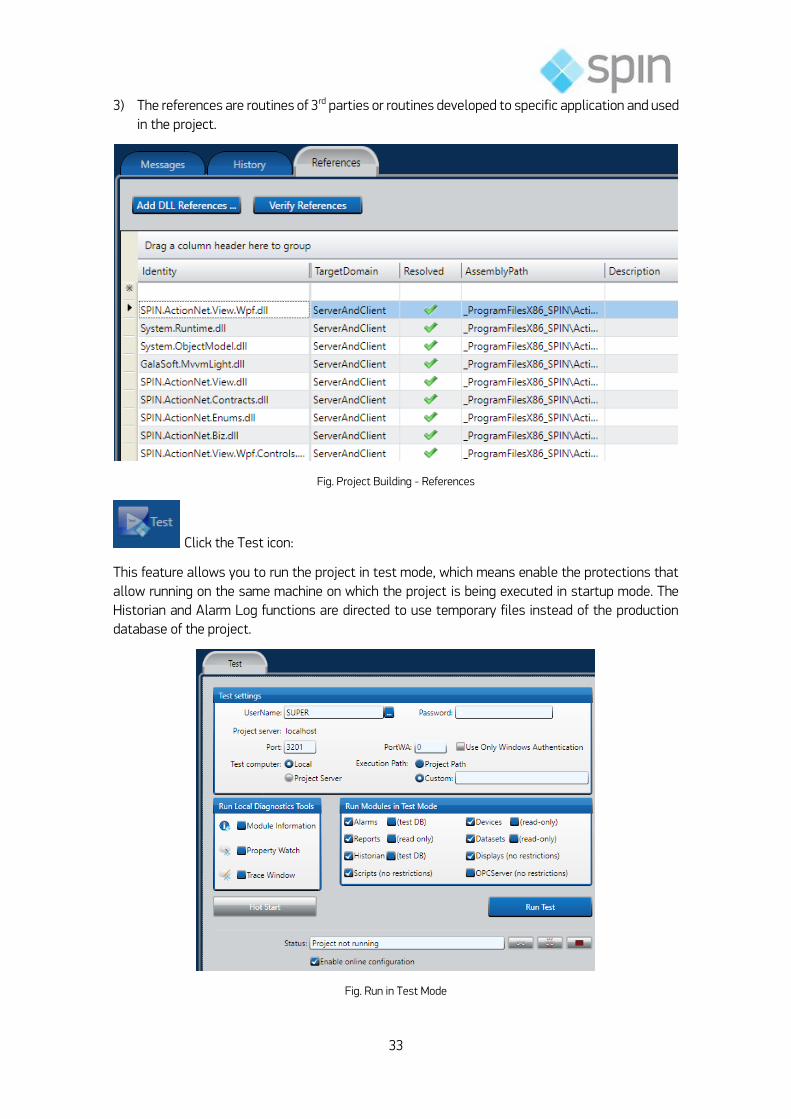
3) The references are routines of 3rd parties or routines developed to specific application and used
in the project.
Fig. Project Building - References
Click the Test icon:
This feature allows you to run the project in test mode, which means enable the protections that
allow running on the same machine on which the project is being executed in startup mode. The
Historian and Alarm Log functions are directed to use temporary files instead of the production
database of the project.
Fig. Run in Test Mode

34
Optionally you can enable diagnostic tools to assist in solving problems, also you can choose to
disable any of the modules of the Action˳NET during the test.
Click the Startup icon:
Starup is where you configure how your project will run in production mode. This will enable log
functions and alarm historian to use databases, as defined in the project, instead of temporary files
used in Test mode.
Fig. Run the project Start Up
Optionally, you can enable diagnostic tools to aid you in resolving any problems, just as if you can
also choose to disable any of the modules Action˳NET o during the test. The Online Setup checkbox
allows settings to be made online. When the project is running, and this option is enabled, all
changes made will be displayed while the project is being executed.
The Online Configuration checkbox allows you to establish on-line configuration. When the Project
is running you can attach to the execution, which means modifications to the project we be shown
in the running project when made.
Click the Publish icon:

35
This feature creates a protected read-only version, suitable for implementation in the field. Running
the Publish command will create a new project file (with extension "teng") with the selected version
number.
The published projects (extensions of "teng") are similar to the current project (".proj” extension)
and can only be opened in read-only mode. This provides you with a safe backup version of
published applications.
Fig. Publication of the Project
The published projects (Tproj Extension file) are similar to projects no published (Tproj Extension
file) but can only be opened in read only mode. This feature allows you to have a secure version of
applications.
Click on UseCount icon:
This area consists of three tabs in the form of read-only reports with information about the use of
the design objects.
This information is updated during execution of BUILD and also for the changes that are being
made in the project.

36
Fig. UseCount – Cross Reference
Use Count - It is a list that shows each of the design objects and the number of times it is
referenced.
Cross Reference - Displays the existing objects in the project, with their names, which are
referenced in the table, having the handle table and the table on which they are defined.
Unused objects - Shows a list with the names of objects defined and were defined in the
module, but which are not referenced in any other part of the project
Click on Dictionaries icon:
This area consists of four tabs with different kinds of dictionaries.
Fig. Dictionaries - Localization
1) Localization: using localization tables users can develop applications that can be localized in
several languages, that is, all messages in the application will be available in more than one
language.

37
When creating applications with location, the user must define the dictionary in Script
"ClientStartUp" (setting the property: @ Client.Dictionary) and should also provide the option
on a screen to select your language. Observe that property location of objects must be
selected for the function to work properly.
2) Enumeration Sets: This tab option allow creating several tables with the association:
“number – descriptions text”. Therefore, you can, for example, associate the status of
switchgears with its description: 0 = Taken out, 1 = Opened, 2 = Closed, 3 = Error.
3) Units: Tables of engineer units that can be associated to tags.
4) Categories: On each project, you can create 64 categories. They will be used, for example, to
Lean Automation methodology. See description forward.
Fig. Categories been used on Tags> objects
Click on Extensions icon:
Extension is one area of routines to import/export information’s from external modules. The default
application already has several extension routines and the user can develop a new ones.
The figure below presents some import routines available in Action˳NET:

38
Fig. Extensions - Import
a) ActionView: Import one project from the SCADA ActionView;
b) Deploy: Generate, automatically, Alarms, events, Historian and I/O points of a substation
project, based on the Utility culture;
c)
d) CSV File: Creates Tag Templates according the CSV file;
e) SinapWise: Import dozens of components from one ADMS/FLISR program. Used to Self-
Healing solution;
f) Project/Component: Import other Action.NET project or components of the project (exported
using export option);
g) Contrologix: Creates the Tag Names, Tag Templates and does the mapping of the PLC
addresses, all according to the information available at the L5K file;
h) OPC: Creates the Tag Names, Tag Templates and does the mapping of the OPC Client
addresses, all according to the information available by browsing to the OPC server;
i) XML: Creates the Tag Names, Tag Templates according the data structure of the XML file, it
also creates the Edit-Datasets-Files configuration to read that file;
j) ˳NET: Creates Tag Templates that matches the selected .NET classes;
k) IEC61850: Creates the Tag Names, Tag Templates and does the mapping of the OPC Client
addresses, all according to the information available by browsing to the IEC61850 over one
SCL file or the IED;
Info Menu
Info environment allows access to current project configuration details.
From the main menu, click the Info icon.
Click the Project icon:
This option presents the design information’s.

39
Action˳NET helps you collect and store information about your project. To manage the versions of
the projects (development, installation, commissioning or maintenance) is important to make sure
that you know which versions of the software, license, and other project settings and information.
Fig. Menu Info
The Project Guide presents the information and allows these to be modified, if necessary. Some of
these fields are also available during execution.
Redundancy
On redundancy folder, if you define two servers (primary and secondary), the software,
automatically defines all shortcuts necessary to run the application and the MMI clients.
Fig. Info Section - Redundancy Folder
Click the Track icon:

40
A key feature in Action˳NET is the ability to track changes in the configuration of the project. This
helps to check the project settings in their various stages of development and implementation.
This is important because you need to know to check which version of the project is being used to
develop enhancements and work through Diagnostics.
Fig. Project Tracking
Action˳NET tracks changes in all aspects of the project. The table names are indicated where
changes have occurred. A double-click on any line of the table displays the Publisher that
originated the change.
The guide provides information related to these changes. Tells you what to change, the specific
module where it took place, the compilation of the specific project in which it occurred, as well as
the date of the change and any arbitrary comments made by the user.
The Releases tab provides information related to the publication date of the design, the author and
the build number of the project at the time of publication.
Click the Notes icon:
Often during the development and implementation of a project, developers need to leave notes for
themselves or for other people who cooperate in the project. In Action˳NET, this can be done using
the Utility Notes.

41
Fig. Notes
The notes are created as a "Post-It" and can be seen by all members of the creative team of the
project. The notes are displayed on your desktop during editing of the project.
Click the Help icon:
Action˳NET includes on Spin Site a comprehensive reference guide for a description of the
development tools. Use the index or search using keywords online.
The site is:
http://www.spinengenharia.com.br/help/an-2014-en/ActionNETUG/ActionNET_-
_Users_Guide_Manual/ActionNETUGCover/ActionNETUGCover.htm
Fig. Help Reference Guide
Click the License icon:
The License tab displays information about the current Action˳NET license. This information is
required if you need technical support, as well will be useful at the time of performing the revision
update.

42
The current tab provides specific information about how many licensed users are currently
available for the engineering mode and runtime.
Fig. Current Project License Information
Exercise 2-1: Design Supervision System
Carefully read the application proposal and reflect about the same with the instructor and
classmates. As a result, create a project in the Action˳NET environment by configuring it to suit
the application. FOLLOW INSTRUCTOR GUIDELINES.
The process to be automated consists of one small substation with one line bay of 134 kV, a
transformer and two bays of feed, according the draw below.
Fig. Exercise – Substation scheme

43
Process Specifications
Aqui deve ser colocada as informações do bay de linha, do transformador e dos bays de
alimentadores.

44
3. Editing the Application
:
Fig. Options of the Engineering module
Each supervisory system manages a certain number of objects also called entities that describe
the controlled process variables and the usual elements of the control. The configuration of a
supervisory activity comprises usually two steps:
a) Define each process variable in the database.
b) Define synoptic, graphics and reports.
In the system there are simple variables, primitive and composed, the latter formed from the first.
In this context, the variable name gets its name from Tag.
The objective of this chapter is to explore the process of editing an application in Action˳NET.
Issue of Application
The following figure illustrates the Edit option whose settings we will explore in the following.
Fig. Menu Edit

45
EDIT>Tags
A "Tag", in the context of a project configuration refers to a process variable. Use the Tags (and
their predefined properties) to set up a database in real-time. The types of Tags available can be
extended and new types can be created.
The following figure shows the tabs of the Tags option.
Fig. Objects (Tags)
EDIT>Tags>Objects
The main settings tab-related Objects are shown in the following figure.
Fig. Edit> Tags> Objects
Name Type Array Parameter StartValue Retentive Description Category
Tag ID Type of variable
Dimension in case of vector
Tag parameters depending on the type
Initial value of tag
Configures the retention of values on shutdown
Detailed description of the Tag
Categories associated with tags (may be several)

46
Fig. Edit> Tags> Objects: RowsCut, Copy, Paste, Delete and Edit
Notes:
On each table, there are several column items, but the system, by default, always shows the
most used (important). If you click the right button of the mouse over the column, the system
shows all items, with a Ѵ on the left side of the presented items.
The types of Tags are Digital, AnalogInt, AnalogDecimal, AnalogDouble, Text, Timer, Counter,
Reference, Date Time, Data Table and User Types. On substation application, usually the
template is the bay type, defied in templates.
In the column Parameters is configured the dead band of the Tags and the Tags tuned Analog
Timer and Counter.
If the column Array is empty, the Tag is not of type Array. Any other value "N" features a Tag
Array (positions 0 to N). For example, if N = 5, a Tag with 6 elements is created (Tag [0] to [Tag
5]).
The options column value retention Retentive are: None (non-retentive), ValueOnly (saves the
value of the Tag) and Properties (saves all properties of Tag).
See, in the product documentation the others types available like: min, max,
unit, format, etc.

47
EDIT>Tags>Templates
Tag templates let you create new tag types that can have multiple attributes.
In Electrical application, we use templates to create bays type, like line, transformers, feeds, transfer, capacitors bank, auxiliary services, etc.
Observe that you can, in one template definition, use a template type and do this in several levels (template of template, of template…).
To create a tag template:
1) Go to Edit >Tags > Templates.
2) Click New.
Create New Tag Template dialog shows.
3) In the New type Name field, enter a name for the tag type. In the Description, enter a description of the tag. Click OK.
The Templates tab displays with the name of the new template at the top of the tab.
4) Click the insertion row to create a new attribute for this tag template.
5) Enter or select information, as needed.
Fig. Edit> Tags> Templates
Column Description
Name Enter a name for the attribute. The system lets you know if the name is not valid.
Type Select the type of variable. Select one of Built-in Tag types or one of the previously defined tag templates,

48
Parameters If available, configure the parameters. The parameters vary based on the tag type.
Array If you need an array, set last array index. For example, if you enter 5, the system creates a tag with six elements (0 to 5).
Description Enter a description of the attribute.
[Other columns]
The Columns on Template Members have the same usage of the columns at EditTagsObjects.
EDIT>Tags> Assets
If you have the Enterprise version of Action˳NET, assets let you configure additional metadata for
your project. For example, you can organize objects in your project, such as tags, devices, and
alarms, into a hierarchy. This lets you group tags that are related to each other. The hierarchy may
reflect such things as, areas of your manufacturing floor or the location of your machinery.
Fig. Edit> Tags> Assets
To create assets:
1) Go to Edit >Tags > Assets.
2) Right-click the project name and select New Level.
3) Enter a name for the level.

49
4) Right-click the new level and select Insert Asset.
The Select Object window displays, with all objects, by type, on the left side.
5) Select the object type from the left side and the object you want from the right side.
6) Click OK.
The object becomes a child of the selected level.
7) Continue adding child or sibling levels and inserting assets, as needed.
If needed, right-click a level to rename or delete, or right-click an asset to delete it.
8) On the Objects tab, for new or existing tags, select the new level in the Level column
The assets can be used as an attribute of the tag objects. When you double click the level attribute,
it shows
Fig. Edit> Objects In Level you associate the asset level of this tag
As example, in a substation, you can have the following levels:
System
o Regional
Substation
line 1 bay
Line 2 Bay
Transformer 1 bay
Transformer 2 bay
Bar 1
Bar 2
Feeder 1
Switch 1
Circuit breaker
o Protections switch breaker
o Measures switch breaker
Switch 2
Switch 3
Feeder 2
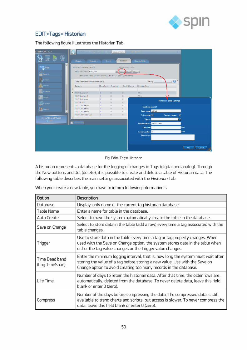
50
EDIT>Tags> Historian
The following figure illustrates the Historian Tab
Fig. Edit> Tags>Historian
A historian represents a database for the logging of changes in Tags (digital and analog). Through
the New buttons and Del (delete), it is possible to create and delete a table of Historian data. The
following table describes the main settings associated with the Historian Tab.
When you create a new table, you have to inform following information’s
Option Description
Database Display-only name of the current tag historian database.
Table Name Enter a name for table in the database.
Auto Create Select to have the system automatically create the table in the database.
Save on Change Select to store data in the table (add a row) every time a tag associated with the table changes.
Trigger Use to store data in the table every time a tag or tag property changes. When used with the Save on Change option, the system stores data in the table when either the tag value changes or the Trigger value changes.
Time Dead band (Log TimeSpan)
Enter the minimum logging interval, that is, how long the system must wait after storing the value of a tag before storing a new value. Use with the Save on Change option to avoid creating too many records in the database.
Life Time Number of days to retain the historian data. After that time, the older rows are, automatically, deleted from the database. To never delete data, leave this field blank or enter 0 (zero).
Compress Number of the days before compressing the data. The compressed data is still available to trend charts and scripts, but access is slower. To never compress the data, leave this field blank or enter 0 (zero).

51
Each historian table has information´s of a group of tags with the same historian characteristics.
You can create as many table as necessary. Each table register will be one tag with the parameters:
Column Description
Name Enter a tag name or click ... to select a tag.
Dead Band When using the Save on Change option in the historian table, the Dead Band is how much the value must change (in EngUnits) for the system to store the value in the historian.
Deviation When using the Time Dead Band option in the historian table, the Deviation is how much the value must change (in EngUnits) for the system to store the value in the historian. This value overrides the Time Dead band logging interval.
RateOfChange
When using the Time Dead Band option in the historian table, the RateOfChange is how much the value must change (in EngUnits) by second, for the system to store the value in the historian. This value overrides the Time Dead band logging interval
Historian Table Select the table that has the settings you want to use for when to save and how long to retain this tag’s value.
EDIT>Tags> Historian Tables
By default, the tag historian database has one table configured. The table settings control when
tag values are written to the historian and how long the values stay in the historian. If you want
some tags to have different settings, you should configure additional tables with the settings you
need and assign tags to the appropriate table.
The table configuration is independent of the Database selected to store the information, as
described in “Historian Database Provider”.
If you want some tags to have different settings, such as the logging interval, you should configure
additional tables with the settings you need and assign tags to the appropriate table. You can also
edit the settings of the default table.
In general, do not store more data than you need. Storing a large amount of data slows the recovery
of that data. You should use triggers and dead bands that are as large as possible, to ensure you
have the information you need, without overloading the system.
Fig. Edit> Tags>Historian Tables
Exercise 3-1: Process Variables
From the exercise 2-1, create two-historian tables:

52
1) A table that store voltage and current of each bay every 5 minutes:
a. line 134 kV and line 13.8 kV;
b. Feeder 1
c. Feeder 2
2) A table that store all changes of circuit breakers, switches, and protections;
Edit> Security
By default, the system logs you in as the Guest user when you start Action˳NET. The Guest user
does not need to enter a user name or password. If you want to secure access to your projects, you
can add users and configure passwords and other settings for each user. The following items can
be configured to adjust the system security:
Adding and Editing Users
Configuring Permissions
Configuring Policies
Real time Inserting / Removing Users.
Fig. Edit> Security>Users
Edit> Security> Users
To add security to your installation of Action˳NET, you can add and edit users. Action˳NET comes
with the following user names configured by default:
Administrator—Built-in user that controls the Security System. No password is configured by
default. You should set a password for this user.
Guest—Used by default to access Action˳NET and when you log off as another user. No
password is configured by default.
User—Use as a generic user. No password is configured by default.
The Administrator-level and Guest-level user IDs have built-in attributes. The Administrator is the
only user who can delete or block users and the only user who can define passwords for Database
DB interfaces. Guest Users are used for anonymous login users, and do not have passwords
assigned to them.
Do not create other users with those names, neither change the row ID of those users, as the
system is hard-coded to assume those users exit with the pre-defined IDs.
You can create as many users as you want.
Column Description
Name Enter a user name. The system lets you know if the name is not valid.

53
Permissions Select the permission group to use for this user. See “Configuring Permissions”.
Password Enter a password for the user. The system lets you know if the password is not valid. You can configure password requirements. See “Configuring Policies”.
Password Hint Enter information that can help you remember the user’s password.
Policy Select the policy settings to use for this user. See “Configuring Policies”
Blocked Select to block the user’s access and flag the user as deleted, without deleting the user. You may want to use this for users who are no longer with your company.
Deleted Select to block the user’s access and flag the user as deleted, without deleting the user. You may want to use this for users who are no longer with your company.
Profile Enter the user’s email address, phone number, and full name
Edit> Security> Permissions
You can configure which functions users can access when editing the project and when using the
runtime. You set permissions using Groups.
Action˳NET comes with a few predefined groups that you can use, or you can create your own.
Fig. Edit> Security>Permissions

54
Column Description
Name Enter a name for the group. The system lets you know if the name is not valid.
Edit Select the functions users in the group can access when editing a project.
Run Select the functions users in the group can access when using the runtime.
Description Enter a description for the group.
The permission groups you create are available for use on the Users tab.
EditSecurityPermissions.Run ‐ Disable Windows applications switch
One option on the Run permissions is to disable to Switch Applications. If disabled, the following
actions/keys will be inhibited for that use:
Access to the Start button and the Task Toolbar.
Windows Logo button
Ctrl + Alt + Del
Ctrl + ESC
Alt + Tab
lt + F4
Windows Logo + L
Attention:
To allow disabling the keyboard short cuts to switch applications, the file
DisableTaskSwitchProtection.bat must be run from the installation directory, in-order to install the
keyboard driver necessary to implement this feature.
Edit> Security> Polices
You can configure settings that you can apply to users. Action˳NET comes with a few predefined
policies that you can use, or you can create your own.
Fig. Edit> Security>Policies
When you click on each line-column with the left button of the mouse, the Action˳NET presents
you the field options. The exception is on description that you fill it up with a description text of the
policy.

55
Column Description
Name Enter a name for the policy. The system lets you know if the name is not valid
Identification Select the password rules for both editing a project and accessing the runtime.
Esign For runtime only. Select to enable a timeout for the runtime login. Enter the timeout period in minutes.
Session For runtime only. Use to enable a timeout for the runtime session. Select what will cause an automatic logoff, and then enter the appropriate values for Inactivity Minutes and Duration Hours. This setting only logs the user off. The application continues to run.
Description Enter a description for the policy.
The policies you create are available for use on the Users tab.
If needed, right-click a row to cut, copy, paste, or delete the row.
Edit> Devices>
This option lets you configure the communication protocols and the form of data acquisition
device(s) connection(s). The following figure shows the tabs of the option Devices.
Fig. Devices Options
Edit>Devices>Channels
The main settings for the Channels tab are shown in the following figure:
Fig. Edit> Devices > Channels
This tab allows configuration of the communication channels and protocols (network physical
layer).
The Protocol can be selected from the drop-down list available in the field Installed
Protocols as shown in the following figure.

56
Fig. Edit> Protocols selection
Note: There is a specific manual for each protocol
A new channel can be created via Create New Channel button as shown below.
Fig. Creating New Channels

57
The following table describes the main settings associated with the Channels tab.
When you click with the left button of the mouse on any channel field, Action˳NET will presents
the field options in the context, like the following figure.
Fig. Channels fields in context
Edit> Devices> Nodes
Nodes in Action˳NET are the devices (Relays, Power meters, PLCs, UTRs, etc.) on the network that
you communicate with. You can also import settings from an OPC server or from other data source.
The main settings tab-related Nodes are shown in the following figure.
Fig. Edit>Devices>Nodes

58
The following table describes the settings associated with the Nodes tab.
Notes:
1) If a reserve station is set and an error occurs on the primary station communication, the system
automatically will try to communicate with the station recently.
2) For Modbus Protocol:
For a Serial interface, the Slave ID is the device slave address on the Modbus network.
Valid addresses are 1-247
For a MultiSerial interface, select the number of the ComPort and enter the Slave ID the
device slave address on the Modbus network. Valid addresses are 1-247.
For a TCPIP interface:
o IP—Identification of the slave device address.
o Port—TCP port where the slave device is connected (default is 502).
o Slave ID—Device slave address on Modbus network. Valid addresses are 1-247.
3) For OPC interfaces:
Service URL—defines the location of the OPC server.
You must configure the DCOM settings to access an external OPC server. Contact
support for assistance.
Refresh Rate—Server refresh rate.
AllTemsSameGroup— Adds all items in a single group OPC. In this way, only one
connection is created with OPC server.
WaitAfterConnect—Time to communicate after the application is running.
Edit> Devices>Points
This selection defines values for the field data acquisition and mappings of Tags. The main settings
associated with the Points tab are shown in the following figure.
Fig. Edit>Devices>Points

59
As you can see on the figure above, when you click in a field, Action˳NET show you a window with
the possible options. On the example above, the type AIF (internal indications) of a DNP 3 protocol.
The following table describes the settings associated with the Points tab.
Notes:
1) The DataType allowed are: Native (protocol-specific), Bit, Byte, Char, Short, Integer, Long,
Dword, ULong, BCD, LBCD, Single, Real, ASCII, Unicode, OPCDateTime, Timer, Counter and
Control.
2) The Modifiers allowed are: Bit, ByteSwap, WordSwap, and Stringlength Array.
3) The scale conversion options are: Scaling, TagMin, DeviceMin and DeviceMax, Tagmax.
Edit> Devices> Access Typer
This section defines the characteristics of the types of common access points on the devices. The
standard access types are: ReadWrite, Write and Read. Custom types of access can be created via
Create New button under Access Types tab.
The following figure illustrates this selection.
Fig. Edit>Devices>Access Types
Column Description
Read
ReadPolling Select when you want to enable read polling.
ReadPollingRate Enter how often to retrieve the address value.
ReadTrigger Enter an object property to tell the system when to read the value.
ReadOnStartup When selected, the system reads the value on startup.

60
ReadStatus Enter an object property to receive the status of the read communication
ReadCompleted Enter an object property to receive an indication that the reading is completed. The value will change between 0 and 1 every time a reading was completed.
Write
WriteEventEnable Select to enable writing of values to the PLC.
WriteEvent Select when to write the value.
WriteTrigger Enter an object property to tell the system when to write the value.
WriteStatus Enter an object property to receive the status of the write communication.
WriteCompleted Enter an object property to receive an indication that the writing is completed. The value will change between 0 and 1 every time a writing was completed.
Settings
AcceptUnsolicited When selected, the system accepts values from the PLC, even if the polling time has not yet elapsed.
UseStaticBlocks Select when you want to use the block command field
BlockCommand Enter a definition for each block that will be created. Check the driver documentation to see if the specific drive uses this filed and the valid values.
Description Enter a description for the access type.
[Other columns] For definitions of other columns that are available in many tables, see Manual.
Edit> Alarms
This option performs the setting of alarm parameters. The following figure shows the tabs
available in the Alarms option.
Fig. Edit>Alarms
Edit> Alarms> Groups
This section defines the behavior of the common alarms to a group of alarms. The main settings
associated with the Groups tab are shown in the above figure.
The following table describes the settings associated with the Groups tab.

61
Column Description
Name Enter a name for the alarm group. The system lets you know if the name is not valid
AckRequired If required, the alarm stays in the alarm list until someone acknowledges the alarm by double-clicking it in the application.
Sound Select the sound that will play when the alarm occurs.
Show Select List for the alarm to display in the alarm window in the application
LogEvents
Select when you want the alarm to be logged to the alarm historian:
None—Alarms are not logged.
Active—Log when alarm is active.
ActiveAck—Log when the alarm is active and acknowledged.
ActiveNorm—Log when the alarm returns to normal.
All—Log all of the above conditions.
Colors
Select the colors you want to use for each state:
Active—Configured alarm is in the alarm state.
Normalized—Configured alarm was in the alarm state, but is no longer in the alarm state and still needs to be acknowledged.
Acknowledged—Configured alarm has been acknowledged, but still is in the alarm state.
AckTimeout Defines a timeout to ack the alarm. If the alarm is not acknowledged after the specified time, the alarm becomes active again
AutoAckTime If the alarm is not acknowledged after the specified time, the system acknowledges the alarm.
Description Enter a description of this alarm group.
Notes:
1) Alarm groups "Warning", "Critical" and "SystemEvents" are built-in and cannot be deleted,
however their names and settings can be changed.
2) Logging options (LogEvents) alarms are: None (no logging), Active (logs when the alarm is
active), ActiveAck (logs when the alarm has been acknowledged), ActiveNorm (logs when the
event is normalized) and All (logs all situations described earlier).
Audit Trail
In the alarms group tab, you can also set the Audit Trail clicking on Settings button. To enable
event logging, select the Enable option. On the left side of the Windows.

62
Fig. Audit Trail
Edit> Alarms> Items
This selection allows you to set Tags to generate alarms under certain conditions. The main
settings tab-related Items are shown in the following figure.
Fig. Edit>Alarms
The following table describes the settings associated with the Items tab.
Column Description
TagName Enter a tag name or click ... to select a tag
Condition
Select the condition you want to use for this alarm event. For DeviationMinor or DeviationMajor, specify a limit, and then use the Setpoint column to set a value or a tag to compare for the deviation.
Limit Enter a value for the alarm limit that corresponds to the condition you selected.
Group Select an alarm group that controls what happens when an alarm occurs.

63
Priority
Enter a priority value that controls where the alarm displays in the list. The higher the number the higher the priority. You can use the same priority for more than one alarm event. Enter 0 (zero) for alarms to be at the end of the list.
Message Enter the text that displays in the alarm list.
Note:
The message body can contain values of Tags when alarms are generated. To do so, add
the name of the Tag in the message using the notation of XAML connection as shown in
the following example:
Value of the Tag = {TagName.Value}.
In order to visualize alarms and events, you can use the built-in object on the displays or
reports.
EditAlarmsItems.Condition
Evaluation condition to generate alarms.
Hi: Tag >= limit
HiHi: Tag >= limit (when acknowledged automatically acknowledges Hi alarm to same Tag)
Lo: Tag <= limit
LoLo: Tag <= limit (when acknowledged automatically acknowledges Lo alarm to same Tag)
RateOfChange: Tag rate of change >= limit
DeviationMinor: Absolute value (tag - Setpoint) > limit (Setpoint defined in the Setpoint column)
DeviationMajor: Absolute value (tag - Setpoint) > limit (Setpoint defined in the Setpoint column)
Equal: Tag = limit
GreaterThan: Tag > limit
GreaterEqual: Tag >= limit
LessThan: Tag < limit
LessEqual: Tag <= limit
Changed: Tag value changed
ChangedUp: Tag value increased
ChangedDown: Tag value decreased
NotEqual: Tag different from limit

64
Edit>Datasets
This option manages access to files and system database. The following figure shows the tabs
available in the option DataSets.
Fig. Edit>Datasets
Edit> Datasets> DBs
Through the DBs tab, you can perform the configuration of the database. The provider may be
selected from a drop-down list available in the field Available Providers. A new connection to a
database can be created via Create New button.
Fig. Datasets providers
The following table describes the settings associated with the DBs tab:
Column Description
Name Enter a name for the database configuration. The system lets you know if the name is not valid.
Provider Select the database provider.
Database If options display here, select the database type.
ConnectionString Enter the information needed to connect to the database.
LogonName Enter a valid login name for the database.
LogonPassword Enter the password that corresponds to the database login.

65
Description Enter a description for the database.
Notes:
1) Default providers for databases are: Odbc Data Provider, OleDb DataProvider, SqlClient Data
Provider, Microsoft SQL Server Compact Data Provider and Spin tDB 4 (direct connection).
2) The list of available databases is created dynamically and is based on the selected provider.
The most common options are: Microsoft Access Database, Microsoft Excel Database, ODBC
using DSN, FILEDSN and SQL Server Database.
3) The LogonPassword field (password to LOGIN) can only be accessed by the administrator (user
ID = 2).
Edit> Datasets> Tables
The Tables tab allows you to configure access to tables in the database previously defined.
The main Tables tab related settings are shown in the following figure
Fig. Edit>Datasets>Tables
The following table describes the settings associated with the Tables tab.
Column Description
Name Enter a name for the table configuration. The system lets you know if the name is not valid.
DB Select the database configuration.
TableName Select the table name.
WhereCondition Specify parameters to filter the data using SQL syntax.
Access Select the access permissions for the table.
Mapping Click ... to select the tags that you want to populate with data from the first row of the table with data from specific columns.
Description Enter a description for the table configuration.
Notes:
The operations permitted on the item Access are: Read, Insert, ReadWrite and
Unrestricted.
In the context of item Mapping, when you run the commands Next and Select the first row
in the selected result is applied to the Tag. On the other hand, the Update command causes
the contents of the Tag to be written in the line.

66
Edit> Datasets> Queries
The Queries tab lets you configure access to rows in the database previously defined. The main
settings tab for Queries are shown in the following figure.
Fig. Edit>Datasets>Queries
The following table describes the settings associated with the Queries Tabs
Column Description
Name Enter a name for the query. The system lets you know if the name is not valid.
DB Select the database configuration.
SqlStatement Enter the query using SQL syntax.
Mapping Click ... to select the tags that you want to populate with data from the query with data from specific columns.
Description Enter a description for the table configuration.
Edit> Scripts
Edit> Scripts >Tasks
Script Tasks are run from the firing (Trigger) process or event in time set in the Interval. To edit a
Script, select it in the list and go to the CodeEditor. The main settings associated with the Tasks
tab are shown in the following figure:
Fig. Edit>Scripts> Tasks
The following table describes the main settings associated with the Tasks tab:
Column Description
Name Enter a name for the task. The system lets you know if the name is not valid.

67
Code Read-only. This defaults to the language selected when you created the project. From the Code Editor tab, you can change the code language. To change the project default, go to Info > Settings.
Trigger Enter or select the event (tag or object) that triggers the task execution. The task executes when the value of the object changes.
Period Enter how often the task should execute.
Domain
Select where the script executes:
Client—Task executes on each client system. These are tasks that apply locally (on the user’s computer), for example, report generation.
Server—Task executes on the server system. These tasks apply across the application, that is, globally.
InitialState
Select the tasks’ s initial state:
Enable—Task is ready to run.
Disabled—Task is not ready to run. Let us you enable the task under specific conditions.
BuildStatus
Read-only. Status of the task code from the continuous compiling process.
Green check mark—Task runs without errors.
Red X—Task has warnings or errors. Double-click to go to the warning or error. Warnings are information only. Errors will prevent the code from running, but only that specific task. The rest of the application will run.
BuildErrors Read-only. Displays any errors encountered during the last build.
Description Enter a description of this task.
Note:
There are four preconfigured tasks. They are: ServerStartup (is performed when the project starts
running; it runs on the server machine where the file TServer.exe is), ServerShutdown (runs at
shutdown; also on the server), ClientStartup (runs on each client machine when the client module
starts to run via TVisualizer.exe file), ClientShutdown (runs on each client machine when the
display module is closed).
Edit> Scripts Classes
Through this tab, the user can access or implement Classes under the Scripts. The concept of class,
in the context of Object-Oriented Programming (OOP) consists of an abstraction that describes the
behavior common to a set of real-world entities. In addition, the object is the basic unit of object
orientation, both for the modeling and implementation of the solution of a problem. An object
encapsulates the behavior and the properties or attributes of a real-world object. Every object is
called an instance of a class.
The main settings tab for Classes are shown in the following figure:

68
Fig. Edit>Scripts> Classes
The following table describes the main Classes tab related settings.
Column Description
Name Enter a name for the class. The system lets you know if the name is not valid.
Code Read-only. This defaults to the language selected when you created the project. From the Code Editor tab, you can change the code language. To change the project default, go to Info > Settings.
Domain
Select where the class executes:
Client—Class executes on each client system. These are Classes that apply locally (on the user’s computer), for example, report generation.
Server—Class executes on the server system. These classes apply across the application, that is, globally.
BuildStatus
Read-only. Status of the class code from constant compiling process.
Green check mark—Class runs without errors.
Red X—Class has warnings or errors. Double-click to go to the warning or error. Warnings are information only. Errors will prevent the code from running, but only that specific class. The rest of the application will run.
BuildErrors Read-only. Displays any errors encountered during the last build.
Description Enter a description of this class.
Notes:
There are two preconfigured classes. They are: ServerMain (library of methods available for all
tasks from the server) and ClientMain (library of methods available for all Scripts, including Scripts
to Display).
Edit> Scripts> Code Editor
In this tab, you can edit the task code and user classes. The programming language options are:
VB.NET and CSharp (C#). For details of the syntax and programming reference, see the language
specific documentation.
The Platform .NET Framework
The .NET Framework also known as .NET is an initiative by Microsoft, which aims to a single
platform for development and implementation of systems and applications. Any generated code
for .NET can be run on any device that has a framework of such a platform. With idea similar to the

69
Java platform, the programmer stops writing code for a specific device or system, and going on to
write for the .NET platform.
The .NET platform runs on a Common Language Runtime-CLR (language-independent execution
environment) interacting with a set of Unified Libraries (framework). This CLR is able to run multiple
programming languages, interacting with each other as if they were a single language. Examples
of supported languages: C#, C++, Java and Pascal.
The .NET platform is based on one of the principles used in Java technology (Jit-JIT Compiler), the
programs developed for it are double-compiled, a distribution (generating a code that is known as
"bytecodes") and another on implementation.
A program is written in any of the programming languages available for the platform and
developer-generated source code is then compiled by the chosen language by generating an
intermediate code in a language called MSIL (Microsoft Intermediate Language).
This new source code generates a file in low-level Assembly language, according to the type of
project:
EXE - Executable Files, Programs;
DLL - Library of functions;
ASPX - Web Page;
ASMX - Web Service.
At the time of implementation of the program, it is compiled again, this time by the JIT compiler,
in accordance with the use of the program.
It is also possible, through specific tools, "precompile" code to prevent the JIT during execution.
More information on: http://www.microsoft.com/net.
Source: http://pt.wikipedia.org/wiki/Microsoft_.NET
The .NET Framework is essential to run several programs that were developed with the use of this
technology from Microsoft. In addition to security, the technology provides platform independence,
with some applications running on Linux, for example. For this software to run correctly, they
require several components that were used by the programmer and must be installed at the time
of execution
The following figure shows the code for the ClientMain class mentioned earlier.

70
Fig. ClientMain Class
Edit> Scripts> Expressions
In several places in Action.NET, you can use expression, using the same syntax described here, to
determine a value or to configure a condition.
Expression are just plain VB.NET expression, such as arithmetic expression or calls to script.class
methods from the project. Intellisense only shows tags and application objects, but the expression
are compiled using the standard VB.Net compiler, so what you would write in the code editor,
should be accepted in expression as well.
Fig. Edit>Scripts> Expressions
Action.NET implements some automated replacements, such as == to =, so the syntax of an
expression is also very close the C# statement, but with no need to add the “;” on the end.
In this way, both VB.NET and C# programmers are able to use seamless the expression fields.
In expression, you do not need to put @ before that tag names. You need the @ in the code editor
to differentiate project tags from .NET variables. However, expression do not have local .NET
variables, so you use the project object directly.
For arithmetic operands, you can use the standard operands as described in the .NET
documentation.

71
To allow single-line evaluations, the .NET language has the IIF command, which currently is used
only with IF. The IF command has three parameters. For example:
IF (A, B, C)
The first parameter is a condition. That method will return B if condition A is true, and it returns C
if the condition is false.
Example: If (tag.A = 1, "True", "False") will return a string according the value of tag.A.
In this .NET method, all three parameters are evaluated independent of the condition. For instance,
if you have IF (tag.A = 1, script.class.client.Func1(), script.class.client.Func2()), both Func1 and
Func2 will always be executed. Only the return value will be different based on the value of tag.A.
The IF or IIF method needs to evaluate the parameters before calling the method. There are many
scenarios where you want to execute only the function according the value.
For that scenario, Action.NET has a method called TIF, which has that behavior.
Therefore, you use the expression:
TIF (tag.A = 1, script.class.client.Func1(), script.class.client.Func2())
Only the Func1() or Func2() will be executed, according the value of Tag.A
The TIF method is defined in the class library that is automatically exposed for expression that are
in the toolkit function library.
The following table describes the main Expressions tab related settings
Column Description
Object Select an existing tag or object.
Expression Enter the expression. The expression can be basic mathematical expression, use a class, or a conditional expression.
Domain
Select where the expression executes:
Client—Expression executes on each client system. These are expressions that apply locally (on the user’s computer), for example, report generation.
Server—Expression executes on the server system. These expressions apply across the application, that is, globally.
Execution
Select when the expression executes:
OnChange—The expression executes when the value of any tag in the expression changes.
TriggerOrPeriod—The expression executes when the trigger event occurs or when the interval set in the Period elapses.
ChangeOrStartup—The expression executes when the value of any tag in the expression changes or at startup.
Trigger Enter or select the tag or object that triggers the expression execution. The expression executes when the value of the object changes.
DisableCondition Enter or select the tag or object that disables the expression execution.
BuildStatus Read-only. Set after you click Verify.
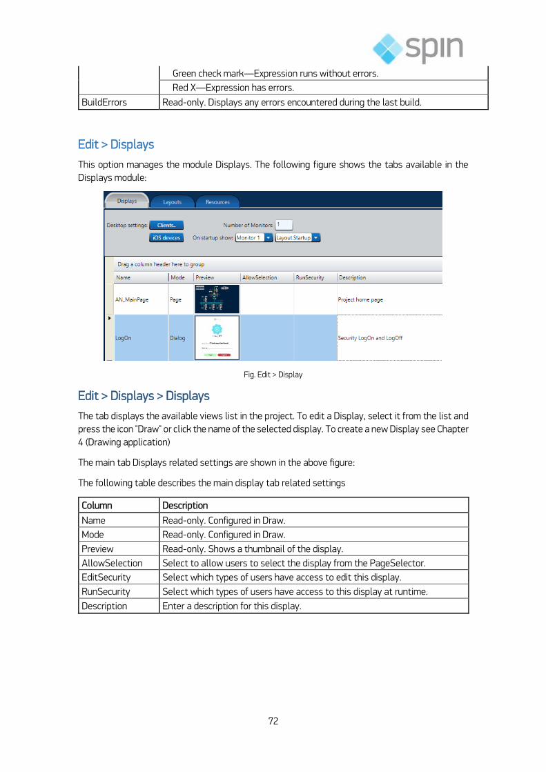
72
Green check mark—Expression runs without errors.
Red X—Expression has errors.
BuildErrors Read-only. Displays any errors encountered during the last build.
Edit > Displays
This option manages the module Displays. The following figure shows the tabs available in the
Displays module:
Fig. Edit > Display
Edit > Displays > Displays
The tab displays the available views list in the project. To edit a Display, select it from the list and
press the icon "Draw" or click the name of the selected display. To create a new Display see Chapter
4 (Drawing application)
The main tab Displays related settings are shown in the above figure:
The following table describes the main display tab related settings
Column Description
Name Read-only. Configured in Draw.
Mode Read-only. Configured in Draw.
Preview Read-only. Shows a thumbnail of the display.
AllowSelection Select to allow users to select the display from the PageSelector.
EditSecurity Select which types of users have access to edit this display.
RunSecurity Select which types of users have access to this display at runtime.
Description Enter a description for this display.

73
Notes:
1) The operating mode includes the following options: Page (is the default mode; when a page is
opened it automatically closes the last page in the current layout), Dialog (opens as a dialog
box, disabling commands on all other open Displays) and Popup (opens as a Popup above the
other Displays and is closed with the opening of another Display).
2) AllowSelection is a function used by the designer to remove selection of pages, test, or other
Displays from the control of the operator, ensuring that the removed items are available only
to specific contexts of application.
The Client Button describes the clients behavior, That is, when you open a client
application, how will work de display. When you click the button, it is opened the
windows below:
Fig. Client Options
The following table describes the main client windows settings:
Column Description
Maximize When Open
Select to maximize the client window to fit the monitor.
Stretch Select how the layout stretches when clients use the application:
When you click over the field
RunSecurity the side Windows is
open asking which clients groups can
open this window.

74
None—Layout does not resize; it displays the exact size you configured for the layout. We recommend selecting the Scrollbar option.
Fill—Layout resizes to completely fill the available space on the client’s monitor, without regard to the layout’s aspect ratio.
Uniform—Layout resizes proportionally to the client’s monitor size, maintaining the layout’s aspect ratio.
UniformToFill—Layout resizes to both maintain the aspect ratio and to completely fill the available space on the client’s monitor. This can result in cutting off some parts of the layout.
Scrollbar Select to have a scrollbar display in the client window.
Title Enter a title for the client window.
MinimizeBox Select to display the standard minimize button.
MaximizeBox Select to display the standard maximize button.
CloseBox Select to display the standard close button.
ResizeBox Select to display the standard resize handle.
Menus
Select which menus display:
File
Tools
Security
Mouse Cursor Visible
Select the mouse pointer to be visible.
OnScreen KeyPad Select to display a numeric keypad.
Disable Web Comments
Select to prohibit application users from sending commands to the PLC.
When Mouse Is Over Command Areas
Select what displays:
Show object edges—
Cursor—Select the type of cursor.
Verify Tag Quality on Client Displays
On undefined quality show—Select option and character to show when PLC determines the data quality is undefined.
On OPC Bad quality show—Select option and character to show when OPC server determines data quality is bad.
Share Logged User at Same Computer
Users can run multiple instances of the application on the same computer. The user may need to log in as a different user from time to time. Select this option to automatically change the logged in user in all running instances of the application on the same computer.
Edit > Displays > Layouts
This tab allows the adjustment of the Layout of Displays.
Layouts are areas (Dock Panels) that define the arrangement of the Displays during the execution.
The last Display listed in Layout is one that will change when executing the command. The other
Displays in the Layout that remain open normally contain information such as navigation menus,
alarm lines and global application information.

75
The project can have only one Layout or the same can be changed dynamically by using the
appropriate command.
Click the New button to create a new Layout. See the following figure:
Fig. New Layout
Click on the + and – buttons to add or delete pages in the list of Layouts and click the arrows to
navigate up or down on the pages. See the detail in the following figure:
Page dimensions and background color can be set by using the commands shown in the following
figure:
The main settings tab related to Layouts are shown in the following figure:
Fig. Page settings

76
Fig. Tab Layout
The following table describes the main settings associated with the Layouts tab:
Column Description
Page Display name used in this
Docking Sets the anchor position for the Display (left, top, right and bottom). Defines the horizontal alignment (left, Center, or right)
Horizontal Align Defines the horizontal alignment (left, Center, or right)
VerticalAlign Sets the vertical alignment (top, Center or bottom)
Note:
The anchor position can be changed by clicking once in the table field and selecting the desired
position.
Edit > Displays > Resources
The tab Resources lists the project images.

77
Used to insert an external image file from your computer into the project configuration, like an icon,
wallpaper, object, or background image. You can manage the imported images at Edit-Displays-
Resources. After the image is imported, you no longer need the original file. Images can be used
are color brush to any drawing object, even be used as “color” or the ColorFill dynamic attributes.
Fig. Import Images
An additional benefit of the resource table is that when an image is replaced in the resource
dictionary, but its name does not change, all references to that image are automatically updated.
Exercise 3-3: Editing Supervision System
Montar exercício baseado no nosso demo.

78
4. Design the Application
This chapter discusses the step Displays drawings and symbols within the supervisory system
design with the Action˳NET
Design of the Application.
Drawn
The design of the application is performed on the menu Draw (to draw). The following figure shows
that menu tabs.
Fig. Draw Menu
Draw > Drawing
The vertical toolbar available in the Drawing (Drawing) allows you to select a component for use
in the application. The selection tool (arrow) present at the top of this bar can be used to move,
group, or change the size of components.
Editing Procedure
1) To add a component to the application proceed as indicated in the following:
2) Select the component via single-click. It will be highlighted.
3) Position the cursor on the area of the screen, then click and hold the left mouse button.
4) At the same time, drag the cursor on the screen area.
5) Release the left mouse button to finish creating the component.
6) Right-click to move on the the next component, or continue adding more of the same type of
component.
7) Click the component with the left mouse button to select it.
8) Then click with the right mouse button to open a context menu, which performs specific actions
of the selected component.
Tip: to select multiple components use Shift + [left mouse button] in the desired items.
Overview of the Vertical Toolbar
The following table describes the functions of the vertical toolbar icons.

79
Notes:
1) An XPS document (XML Paper Specification) is a document format that you can use to view,
save, share, digitally sign, and protect your document's content. The XPS document is like an
electronic sheet of paper: you cannot change the content on a sheet of paper after printing,
and you cannot edit the contents of an XPS document after you save it in the XPS format. In
this version of Windows, you can create an XPS document in any program of printing, but may
only display, sign, and set permissions for XPS documents in the XPS Viewer. (Source:
http://windows.microsoft.com)

80
2) The Microsoft Windows Presentation Foundation (WPF) provides an integrated platform for
building highly comprehensive and visually differentiated applications. Windows Presentation
Foundation is a next-generation presentation subsystem that unifies a complete set of output
services: user interface, creating drawings and 2D and 3D images, printing and document-
based processing, speech, and audio and video services. Windows Presentation Foundation
also introduces a new declarative programming model code-named "XAML", which enables
user interfaces to be specified as a hierarchy of objects with properties and logic. XAML
separates the UI design of the code in an orderly manner, allowing graphic designers to create
attractive user interfaces and refined and that developer’s focus on application logic. This
collaborative model of application development enables developers and designers to work
efficiently and integrated. Moreover, the creation and the XAML usage is simpler for the tools,
and the XAML can be compiled into an application alongside classes written in any CLS-
compliant language, such as Visual Basic and c #. (Source: http://msdn.microsoft.com)
3) The trend chart plots a graph of trend data of a given variable, typically analog, in function of
time. The user must define two things:
Which variables are sampled by the system synchronously with a clock and how often
For each graph, which of the registered variables should be displayed simultaneously on
the same screen
Sampling periods ranging typically from 100 ms to 1 second should be chosen according to the
actual speed of the process. It is normal to choose a time period for each type of the variable
(temperature, level, pressure, etc.). The data is typically stored in a circular buffer of size B bytes.
The total period of storage of data will depend on the sample period and b. The selection of the
desired Display for viewing can be done using the check box shown in the following figure:
Fig. Display Selection
Horizontal toolbar
The horizontal toolbar contains commands to combine, combine, align and lock the component (s)
selected. The following figure illustrates this bar.

81
Fig. Horizontal Toolbar
Complementary Study
See, in the product's documentation, the functionality associated with the horizontal toolbar, Draw
menu describing them.
Draw > CodeBehind
The CodeBehind tab (associated code) defines the functions linked to each Display. See the
following figure:
Fig. Code Associated With Draw
These functions can be performed when opening or closing, or when the Display is open depending
on how it has configured your code. The associated code can be used to define commands and
mouse input via methods to be run under a specific Display.
Available methods:
DisplayOpening: executed when the screen opens.
DisplayIsOpen: called on a regular interval while the screen is open.
DisplayClosing: executed when the screen is closed.
DialogOnOK: dialogue-type screens use this method, which is called when the OK button is
pressed. If the method returns TRUE, the dialog is closed; if it returns FALSE the dialog remains
open. This method is typically used to ensure data validation in dialog (which prompts the user
to correct incorrect entries before closing the dialog).
Tip: you can add your own variables and .NET methods on this page.

82
Draw > Symbol
This tab, as shown in the following figure, lists the symbols of the application with its dynamic
properties and drawing.
Fig. Draw> Symbol
To create a symbol, select an object in the drawing area, right-click the mouse and run the
command Make new symbol, as shown in the following figure:
Fig. Create a Symbol

83
Tip: to simplify the use of symbols in other fabrics and applications, you can define LABELS
on dynamic properties where a Tag is expected.
You can also create and save your symbols. See an example in the following figure.
Fig. Create a new Symbol and save in a library
Using Lean Automation, you create a library of all substations equipment’s and IEDs.
The Settings Object(s) Selection(s)
The menu bar on the left includes the settings of the object(s) selected, as shown below.
Fig. Left menu associated to a circuit Breaker symbol

84
The following table describes the settings in the menu bar to the right.
(*)The dynamics of the symbol can be associated with one of the profiles shown in the following
figure, which can be accessed via Menu Dynamics and Configure button.
Fig. Dynamics of the symbol
The following table details these dynamic profiles for the symbol.
Dynamic description
Action Performs actions triggered by the user interface
Shine Changes the appearance of the object dynamically
Hyperlink Opens a hyperlink
Security Defines the permissions of the object in the running
Bargraph Associate de object to a bar graph (0-100%)
LineColor Colorize the line around the object
Visibility Changes the visibility and opacity of the object dynamically
MoveDrag Moves the object dynamically
Scale Changes the size of the object dynamically
Rotate Rotates the object dynamically
Skew Deform the object dynamically

85
Exercise 4-1: Design of the Supervisory System
Definir exercícios associados ao demo

86
5. Running the Application
The runtime (Run) provides access to all the resources of project implementation.
Application Execution
The following modules are available: Build, Test, Startup and Publish). In addition, the following
tools are included: UseCount, Localization and Extensions. The following figure shows the options
in the run-time environment:
Fig. Run Menu
Run > Build
Run > Build > Messages
Displays the current status of the project under build.
Before publishing a new version and after successive modifications in the project, execute a build
to create a new label for the project. Select the option “Pack database after build” (Stack the
database after compilation) to reorganize and optimize all database tables. This will improve the
performance during execution. The Build button. (Compile ...) starts the build process. The following
figure shows the tab Messages to build.

87
Fig. Run Menu
The following table describes the main settings related to Messages tab.
Run > Build > History
The following figure shows the tab History of compilation.
Fig. Run> Build > History
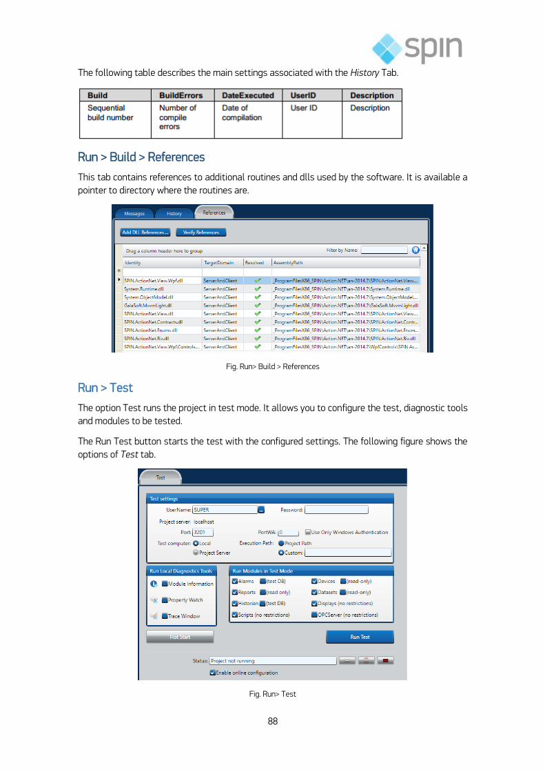
88
The following table describes the main settings associated with the History Tab.
Run > Build > References
This tab contains references to additional routines and dlls used by the software. It is available a
pointer to directory where the routines are.
Fig. Run> Build > References
Run > Test
The option Test runs the project in test mode. It allows you to configure the test, diagnostic tools
and modules to be tested.
The Run Test button starts the test with the configured settings. The following figure shows the
options of Test tab.
Fig. Run> Test

89
Select the Online configuration option enabled to establish an online configuration before starting
the project. If the same were started without this option checked, it would only be applied on the
next run.
In test mode, click the button to link to a project in execution. This will allow you to change
the project in execution.
The button allows you to disconnect from the project in execution.
The button terminates execution.
The username selected must have permissions of startup and shutdown of the application.
In the Test settings, you can set the user name and password. In addition, the server and here pops
up the window where the project will be executed.
The project can run on a local or remote server. In this case, the destination is specified in the
option Execution Path. The syntax of the custom option is
c:\\<path>\ name_of_file.com and with maximum 2048 characters.
Diagnostic Tools Place of Execution
In the Run box Site Diagnostics Tools the following tools can be selected: Module Information,
Property Watch and Trace Window.
Modules Run in Test Mode
In the Run box Modules in Test Mode you can select the modules Run in test mode. All Tags
(alarms and historians) are saved in temporary files. In addition, no command or value are sent to
the process. The values associated with devices and datasets are read-only. The Scripts and
Displays OPC Server are run without restrictions. In the case of reports, no file is saved.
Run > Startup
The Startup option runs the project in full execution mode. It allows you to configure the startup,
diagnostic tools and modules to be initialized.
The button Run Startup starts the execution of the project with the configured settings.

90
Fig. Run> StartUp
The settings indicated in the boxes that make up this module are similar to those previously
analyzed test modules.
Run > Publish
The Publish option publishes the project for the purposes of completion of the installation. When
this command is executed, a new project file (with the extension "teng") is created with the version
number selected. The syntax is: <Name_of_Project>-vN.N.teng. The following figure shows the
options of Publish tab.
Fig. Run> Publish
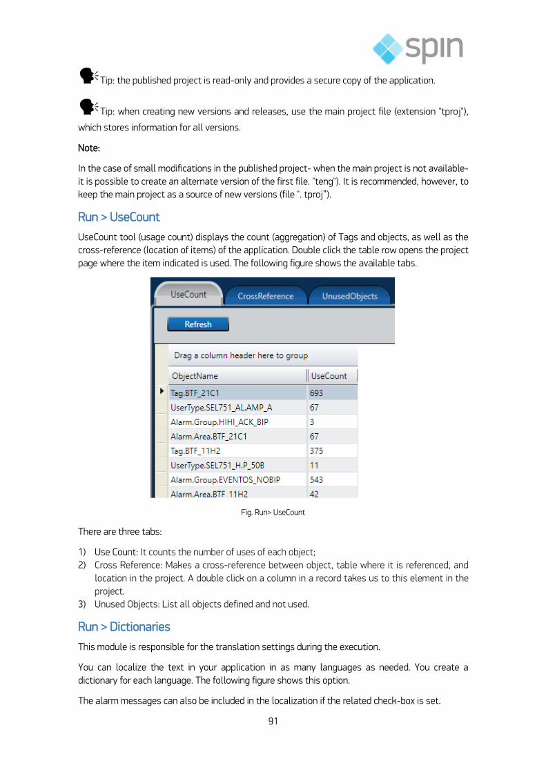
91
Tip: the published project is read-only and provides a secure copy of the application.
Tip: when creating new versions and releases, use the main project file (extension "tproj"),
which stores information for all versions.
Note:
In the case of small modifications in the published project- when the main project is not available-
it is possible to create an alternate version of the first file. "teng"). It is recommended, however, to
keep the main project as a source of new versions (file ". tproj”).
Run > UseCount
UseCount tool (usage count) displays the count (aggregation) of Tags and objects, as well as the
cross-reference (location of items) of the application. Double click the table row opens the project
page where the item indicated is used. The following figure shows the available tabs.
Fig. Run> UseCount
There are three tabs:
1) Use Count: It counts the number of uses of each object;
2) Cross Reference: Makes a cross-reference between object, table where it is referenced, and
location in the project. A double click on a column in a record takes us to this element in the
project.
3) Unused Objects: List all objects defined and not used.
Run > Dictionaries
This module is responsible for the translation settings during the execution.
You can localize the text in your application in as many languages as needed. You create a
dictionary for each language. The following figure shows this option.
The alarm messages can also be included in the localization if the related check-box is set.

92
On Info-Project-Settings, you can also define the default Culture Information that the application
is using and the runtime property Client.CultureInfo allows you to change it during runtime. Some
display controls may get the Culture Info directly from the Operating System, so the correct
procedure is to have both the Operating System setting and the project settings with the target
culture to run the application.
Fig. Run> Dictionaries
Run > Dictionaries > Localization
There are several tables, one for each language to be translated from the original language.
The user interface messages on the screens of the application can be changed dynamically. This
table defines the dictionaries to be used. The next figure show a bilingual project.
Fig. Bilingual project
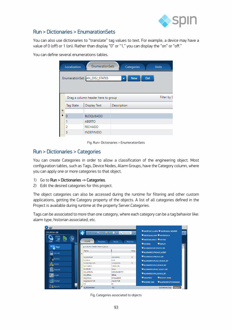
93
Run > Dictionaries > EnumarationSets
You can also use dictionaries to “translate” tag values to text. For example, a device may have a
value of 0 (off) or 1 (on). Rather than display “0” or “1,” you can display the “on” or “off.”
You can define several enumerations tables.
Fig. Run> Dictionaries > EnumerationSets
Run > Dictionaries > Categories
You can create Categories in order to allow a classification of the engineering object. Most
configuration tables, such as Tags, Device Nodes, Alarm Groups, have the Category column, where
you can apply one or more categories to that object.
1) Go to Run > Dictionaries -> Categories.
2) Edit the desired categories for this project.
The object categories can also be accessed during the runtime for filtering and other custom
applications, getting the Category property of the objects. A list of all categories defined in the
Project is available during runtime at the property Server.Categories.
Tags can be associated to more than one category, where each category can be a tag behavior like:
alarm type, historian associated, etc.
Fig. Categories associated to objects

94
Run > Extensions
The module Extensions performs some tools and "Add-ons".
It can be used to import data from a Known source or export data from this project to a particular
destination.
The extensions are developed by Spin or also by the user; do make easier a data manipulation that
will be repeated several times.
Fig. Run > Extensions
As an example, below a window opened when you double click Import IEC61850. The routine ask
by the IP of an IEC61850 IED or an SCD file. When the right information is read, an IEC6150 browser
is opened to import tags from the defined origin.
Fig. Run Import IEC61850

95
Some of the import Tools available are:
Import Action.NET Projects: Add the components of the selected project into the current
project.
Import Rockwell ControlLogix: Creates the Tag Names, Tag Templates and does the mapping
of the PLC addresses, all according to the information available at the L5K file.
Import OPC server configuration: Creates the Tag Names, Tag Templates and does the
mapping of the OPC Client addresses, all according to the information available by browsing to
the OPC server
Import from OSIsoft PI System: When connecting with PI System Historian Servers, it
automatically creates the link with the PI Tags, elements and attributes from PI AF servers.
When connecting with PI AF, it automatically brings the definition of all templates and asset
elements in the selected database, as well as the mapping to communicate with server.
The Import PI wizard will only show on licensed installations with the PI Connection module
enabled.
Importing XML tag templates: Creates the Tag Names, Tag Templates according the data
structure of the XML file, it also creates the Edit-Datasets-Files configuration to read that file
Importing .NET classes from a DLL: Creates Tag Templates that matches the selected .NET
classes.
Exercise 5-1: Implementation of the System of Supervision
Definir exercícios conforme Demo
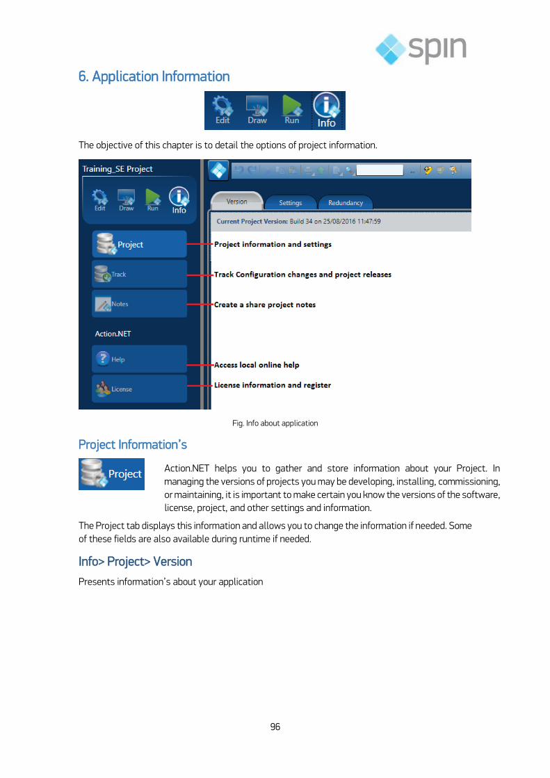
96
6. Application Information
The objective of this chapter is to detail the options of project information.
Fig. Info about application
Project Information’s
The Project tab displays this information and allows you to change the information if needed. Some
of these fields are also available during runtime if needed.
Info> Project> Version
Presents information’s about your application
Action.NET helps you to gather and store information about your Project. In
managing the versions of projects you may be developing, installing, commissioning,
or maintaining, it is important to make certain you know the versions of the software,
license, project, and other settings and information.

97
Fig. Info> Project> Version
Info> Project> Settings
Presents the selected options of the version, as you can see in next figure.
Fig. Info> Project> Settings

98
Info> Project> Redundancy
You can configure application redundancy by configuring two computers as servers. One computer
will be the primary, and the other will be the secondary or hot standby. If the primary computer or
connection to the computer fails, the system automatically fails over to the secondary computer.
Fig. Info> Project> Redundancy
The command line are generated automatically and users should copy it and paste in the servers
and clients, respectively.
Column Description
Primary Server IP and Port
Enter the IP address and port of the primary server.
Secondary Server IP and Port
Enter the IP address and port of the secondary server, if any.
On Primary Startup Select the option you want.
Historian Replication
Select how to handle historian replication.
Connection Timeout
Connection timeout time, in seconds, to switch to secondary server.
Server Command Line
Read-only field populated based on the fields above. Click Copy to Clipboard to copy the command for use.

99
Track Project Changes
and working through diagnostics
Action.NET tracks changes to every aspect of the project configuration. Table names displayed,
and indication is made where changes have occurred. Double-clicking on any line in the table brings
you to the editor which generated in the change.
The Changes tab provides information regarding the specific module where changes occurred, the
specific change that was made, the specific project build in which the change occurred, as well as
the date of the change and any arbitrary comments made by the user. The Releases tab provides
information regarding the date of when a project was published, who published it, and the project
build number when published.
Fig. Info> Track> Tables
The changes tracked are:
Tables: Show the tables changes since the project beginning;
Changes: show the object changes, like tags, symbols, scripts, displays, etc.
Releases: track releases changes.
Notes Shared between developers
Within Action.NET, that can be done by using the Notes utility
A key feature in Action.NET is the ability to track changes in the project
configuration. This helps in verifying project configurations in various stages of
development and implementation. This is important because you need to be able to
verify which version of a project you are using when developing enhancements
Many times during the development and implementation of a project, developers
need to be able to leave notes for themselves, or for others collaborating on the
project.

100
Fig. Info> Notes
Notes created are of a "Post-It"-type, and are viewable by all Project design team members. Notes
are visible on the desktop when editing the Project.
License Information
This information will be helpful if you contact us for technical support, and when it is time to update
to a new revision.
Fig. Info> Licensing
The License tab presents information regarding the currently installed license for
Action.NET.