sbc features and principles
TRANSCRIPT

Quidway SessionEngine2000 Series
Feature Description Contents
Issue 02 (2007-06-30) Huawei Technologies Proprietary i
Contents
2 Features and Principles ........................................................................................................2-1


Quidway SessionEngine2000 Series
Feature Description Figures
Issue 02 (2007-06-30) Huawei Technologies Proprietary iii
Figures
Figure 2-1 Networking of adopting default route...............................................................................................2-7
Figure 2-2 Networking adopting a VRRP virtual router.....................................................................................2-8
Figure 2-3 Typical networking of SE2000 backup .............................................................................................2-9
Figure 2-4 SE2000 backup state.......................................................................................................................2-10
Figure 2-5 Hierarchical protocol relation between VRRP management group and backup groups .................2-11
Figure 2-6 Data channel for transferring VGMP packets .................................................................................2-13
Figure 2-7 Relation between VRRP management group and backup group ....................................................2-14
Figure 2-8 Networking diagram of the SE2000 in master/backup mode .........................................................2-15
Figure 2-9 Data path in master/backup mode...................................................................................................2-16
Figure 2-10 Hierarchical protocol relation between VRRP backup group, VRRP management group and HRP
...........................................................................................................................................................................2-17
Figure 2-11 Register flow.................................................................................................................................2-19
Figure 2-12 Call flow .......................................................................................................................................2-20
Figure 2-13 Media processing flow..................................................................................................................2-21
Figure 2-14 Typical networking application of the SE2000.............................................................................2-22
Figure 2-15 Communication between the SE2000 and Softx3000...................................................................2-23
Figure 2-16 Typical networking in single domain mode ..................................................................................2-24
Figure 2-17 Typical networking in multi-domain mode...................................................................................2-25
Figure 2-18 IP addresses related to the SE2000 ...............................................................................................2-25
Figure 2-19 Ports related to the SE2000...........................................................................................................2-27
Figure 2-20 Typical signaling stream and media stream of the SE2000 media stream bypass process............2-28
Figure 2-21 Networking diagram of address overlapping ................................................................................2-30
Figure 2-22 Networking model of the UDP tunnel ..........................................................................................2-32
Figure 2-23 UDP tunnel header........................................................................................................................2-33
Figure 2-24 UDP tunnel packet structure .........................................................................................................2-33
Figure 2-25 Schematic diagram of signaling and media stream direction when the SBC function is disabled on
the SDD.............................................................................................................................................................2-35
Figures
Quidway SessionEngine2000 Series
Feature Description
iv Huawei Technologies Proprietary Issue 02 (2007-06-30)
Figure 2-26 Schematic diagram of signaling and media stream direction when the SBC function is enabled on
the SDD.............................................................................................................................................................2-36
Figure 2-27 Networking diagram of SDD hot-system hot backup ...................................................................2-37
Figure 2-28 Networking diagram of signaling and media stream in the C-BGF feature..................................2-38

Quidway SessionEngine2000 Series
Feature Description Tables
Issue 02 (2007-06-30) Huawei Technologies Proprietary v
Tables
Table 2-1 Device state in master/backup mode ................................................................................................2-15


Quidway SessionEngine2000 Series
Feature Description 2 Features and Principles
Issue 02 (2007-06-30) Huawei Technologies Proprietary 2-1
2 Features and Principles About This Chapter
The following table shows the contents of this chapter.
Section Description
2.1 Attack Defense This section describes attack defense.
2.2 Dual-System Hot Backup This section describes the dual-system hot backup.
Error! Reference source not
found.Error! Reference
source not found.
This section describes dual-homing.
2.3 Full Proxy of NAT This section describes the full proxy of NAT traversal.
2.4 Address Overlapping This section describes the address overlapping.
2.5 UDP Tunnel This section describes the UDP tunnel.
2.6 Large Capacity This section describes the large capacity.
2.7 C-BGF This section describes the C-BGF.
2 Features and Principles
Quidway SessionEngine2000 Series
Feature Description
2-2 Huawei Technologies Proprietary Issue 02 (2007-06-30)
2.1 Attack Defense
The network attacks intrude or destroy network servers or hosts to steal sensitive data on the
servers or interrupt server services. Certain network attacks even directly destroy network
devices. In the event of a network attack, the service becomes abnormal or even stops
functioning.
The attack defense of the SE2000 can detect various types of network attacks and take the
measures to protect internal networks from malicious attacks. As a result, the SE2000 can
ensure that the internal networks and systems run normally.
2.1.1 Types of Network Attacks
Network attacks can be classified into the following three types:
� DoS attack
� Scanning and snooping attack
� Defective packet attack
DoS Attack
The Denial of Service (DoS) attack attacks a system by sending a large number of data
packets. As a result, the system cannot receive requests from valid users or the host is
suspended and cannot work normally.
The DoS attacks include:
� SYN Flood
� Fraggle
� ICMP
� UDP Flood
The DoS attack differs from other types of attacks. In the DoS attack, attackers prevent valid
users from accessing resources or routers. In other types of attacks, attackers search for
ingresses of internal networks.
Scanning and Snooping Attack
The scanning and snooping attack detects a potential target by identifying an existing system
in the network by means of ping scanning (including ICMP and TCP). Through TCP and UDP
port scanning, the attacker detects the running system and monitors its services and then gets
a general idea of its service type. The attacker also traces the potential security defect of the
system so as to prepare for the further intrusion.
Defective Packet Attack
The defective packet attack sends a defective IP packet to the destination system so that the
system crashes when it processes the IP packet. The defective packet attacks include Ping of
Death and Teardrop.

Quidway SessionEngine2000 Series
Feature Description 2 Features and Principles
Issue 02 (2007-06-30) Huawei Technologies Proprietary 2-3
2.1.2 Typical Network Attacks
Signaling Attack
The signaling attack attacks a system by sending a large number of SIP, MGCP and H.323
signaling.
In case of a Flood attack, the SE2000 discards packets once a fault occurs. In case of a
signaling attack, the SE2000 classifies the signaling into different priority queues according to
the user registration and user access statistics. The users with a higher priority enjoy more and
higher-level services, and the users with a lower priority enjoy less and lower-level services.
Thus, the SE2000 can protect itself and the Softx3000 as well as provide services for valid
users.
On the SE2000, the unregistered users have a lower priority and the registered users have a
higher priority. The users who are prone to attack have a lower priority and the normal users
have a higher priority.
Fraggle Attack
The Fraggle attack is similar to the Smurf attack, but the Fraggle attack attacks a network by
sending a UDP packet instead of an ICMP packet. After receiving the UDP packets, both the
UDP port 7 (ECHO) and 19 (Chargen) respond to the packets. The port 7 responds with the
packet which is the same as the received packet, while the port 19 generates a character string.
Thus, a large number of response packets are generated and returned to the source host and as
a result, the source host crashes.
The attacker sends UDP packets to the subnet broadcast address. The source addresses of
these UDP packets are the IP addresses of the attacked host or network. Port numbers of hosts
in the subnet are 7 or 19. The Fraggle attack causes each system to respond to the attacked
host and then a large number of packets are sent; as a result, the network is congested or the
attacked host crashes. If the Fraggle attack is disabled in the subnet, the system generates an
ICMP unreachable message that continues to occupy the bandwidth. If the source port of the
attacked host is "Chargen" and the port of the target host in the subnet is "ECHO", response
packets are generated continuously. The Fraggle attack, thus, becomes more harmful to the
attacked host.
Land Attack
The Land attack configures both the source address and the destination address of a TCP SYN
packet as the IP address of the attack target. Thus, the target sends the SYN-ACK message
and sends back the ACK message to the target itself, forming a null connection. All the null
connections exist until timeout. Different targets have different responses to the Land attack.
For instance, many UNIX hosts will crash while the Windows NT hosts slow down.
Ping of Death Attack and Extra-Large-ICMP Packet Attack
The extra-large-ICMP packet attack attacks a network system by sending large-sized ICMP
packets.
The Ping of Death attack is a particular case in the extra-large-ICMP packet attack. The field
length of an IP packet is 16 bits and the maximum length of an IP packet is 65535. If the data
length of an ICMP request packet is greater than 65507, the entire length of the ICMP packet
(ICMP data + IP header 20 + ICMP header 8) will be greater than 65535. Upon receiving such
a packet, the routers or systems may crash, die or reboot.

2 Features and Principles
Quidway SessionEngine2000 Series
Feature Description
2-4 Huawei Technologies Proprietary Issue 02 (2007-06-30)
WinNuke Attack
The WinNuke attack causes a NetBIOS fragment overlap by sending an Out-Of-Band (OOB)
data packet to the NetBIOS port (139) of the specific target that is installed with the Windows
system. The WinNuke attack causes the target host status to be Down. Besides, an IGMP
fragment packet can also cause the target host to be Down. This is because the IGMP packet
cannot be fragmented and few systems can resist the attack caused by an IGMP fragment
packet. If a host receives an IGMP fragment packet, it means that the host is under a WinNuke
attack.
SYN Flood Attack
The TCP/IP protocol stacks permit only a restricted number of TCP connections due to the
limited resources. The SYN Flood attacker takes advantage of the situation to forge a SYN
packet with a fake source address or a non-existent address and initiates a connection to the
server. The server, therefore, will not receive any ACK packet for its SYN-ACK response
packet and semi-connection forms. A large number of such semi-connections will exhaust the
network resources. As a result, valid users cannot access the network until the
semi-connections time out. The SYN Flood attack also takes effect in the applications whose
connection number is not limited to consume system resources such as the memory.
ICMP and UDP Flood Attack
The ICMP and UDP Flood attack sends a large number of ICMP messages (such as ping) and
UDP packets to the specific target to seek response in a short time. The target system is
therefore unable to process valid packets normally.
IP Spoofing Attack
To get an access authority, an intruder generates a packet with a fake source address. This fake
source address allows an unauthorized client to access the system by applying the IP
authentication even in the root authority. This may destroy the system even though the
response packet does not reach the system. This is known as the IP Spoofing attack.
Address/Port Scanning Attack
Address/port scanning attack detects the target address and port via scanning tools. The attack
traces the active system and connects to the target network to receive responses from the
system and the port. The system and the port are used by the host to provide services.
ICMP Redirect and ICMP Unreachable Packet Attack
Normally, the network device sends the ICMP redirect packets to the hosts in the same subnet
to request the hosts to change their routes. The malicious attacker, however, may send a fraud
redirect packet to the host in another network to change the host's routing table and to disturb
the host's normal IP packets forwarding.
On receiving the ICMP packets that cannot reach the network (the code is 0) or the host (the
code is 1), some systems consider the subsequent packets sent to this destination to be still
unreachable. The system then disconnects the destination and the host.
Route Record, Source Route and Timestamp Attack
The following three IP packet options are used to test or debug the network.

Quidway SessionEngine2000 Series
Feature Description 2 Features and Principles
Issue 02 (2007-06-30) Huawei Technologies Proprietary 2-5
� Route-Record records the routers through which the packets pass before arriving at the
destination.
� Source-Route shows a route that goes across the Internet specified by the source host.
� Timestamp records the time and the date when the router processes data.
They, however, may be used to probe the architecture of the Intranet viciously.
Teardrop Attack
The More Fragment (MF) bit, Offset field and Length field in an IP packet show which
segment of the original packet is contained in this fragment. Some systems running TCP/IP
crash when they receive a bogus segment containing an overlap offset. The Teardrop attack
makes use of the flaw of some systems that do not find the validity of fragment information to
attack the system.
IP Fragment Packet Attack
Some fields in the IP packet are related to fragmentation, such as Don't Fragment (DF) bit,
More Fragment (MF) bit, Fragment Offset and Length.
If the following problems occur and they are not given proper handling, the device is affected
and even breaks down.
� DF bit and MF bit are set at the same time or fragment offset is not 0.
� DF bit is 0 but fragment offset + length > 65535.
In addition, the device must directly discard the fragment packet, whose destination address is
the same as the device address, because such a packet burdens buffer and reassembly of the
destination device.
Smurf Attack
The simple Smurf attack attacks a network by sending an ICMP request to the broadcast
address of the target network. All the hosts in the network respond to the request and thus the
network is congested.
The advanced Smurf attack attacks the target host by setting the source address of the ICMP
request packet as the address of the target host to crash the host finally. The attack takes effect
when so many attack packets are sent out over a long period that the network is congested.
Theoretically, the more hosts are in the network, the more obvious the effect is. Another new
form of the Smurf attack is Fraggle attack.
Tracert Packet Attack
By tracing the paths of a returned ICMP timeout packet with Time to Live (TTL) value being
0 and ICMP port-unreachable packet, the Tracert attack can pry into the architecture of the
network.
2.1.3 Monitor Technologies in Attack Defense
In the attack defense, you can check whether the network is suffering from the attack
according to the abnormal data detected on the SE2000.
The data to be detected includes:
� CPU utilization of the SE2000

2 Features and Principles
Quidway SessionEngine2000 Series
Feature Description
2-6 Huawei Technologies Proprietary Issue 02 (2007-06-30)
� Traffic that passes the SE2000
When the CPU utilization of the SE2000 exceeds the upper limit, an alarm about abnormal
CPU utilization is raised. When the CPU utilization restores its normal state, an alarm about
normal CPU utilization is raised.
When the traffic that passes the SE2000 exceeds the upper limit, an alarm about abnormal
traffic is raised. When the traffic reduces to less than the value of "the threshold x the security
coefficient", an alarm about normal traffic is raised.
2.1.4 Call Admission Control
Call Admission Control (CAC) is mainly used to limit:
� Total number of registered users
� Number of the concurrent calls
� User register rate
� Call rate
The total number of registered users and the number of the concurrent calls are limited for all
users who pass the SE2000. The limit on register rate and call is applied to specific users.
When the connection rate of a user is too fast, its connection is limited.
In abnormal conditions, the CAC can protect the SE2000 and Softx3000, and provide services
for normal users.
2.1.5 Session-based CAR
Committed Access Rate (CAR) is used to control the traffic of packets. The SE2300 classifies
the packets according to pre-set matching rules. For the packets without traffic control, the
SE2000 forwards them directly. For the packets with traffic control, the SE2300 limits its
bandwidth according to pre-set rules of traffic control.
Based on the session-based CAR technology, users can get various bandwidths of media
stream and Differentiated Services CodePoint (DSCP) value. A maximum of 16 CAR levels
can be pre-set, with different bandwidths and DSCP values at each level.
The matching policy between end users and CAR levels are listed below:
� If the registered user on the SE2300 is a caller, you should match the called number first
(for MGCP and H.248 users, you must match domain name first), and then match the
calling number.
� If the registered user on the SE2300 is a callee, you must match only the called number.
After the matching succeeds, the user can obtain bandwidth and DSCP value of the
corresponding level.
If session-based CAR technology is adopted, we can allocate network resources more flexibly,
guarantee the quality of service, and prevent bandwidth embezzlement at the same time.

Quidway SessionEngine2000 Series
Feature Description 2 Features and Principles
Issue 02 (2007-06-30) Huawei Technologies Proprietary 2-7
2.2 Dual-System Hot Backup
2.2.1 Stand-alone Default Route
Usually, each host on an internal network is configured with a default route to the next hop,
which is the IP address of the egress router; that is, 10.100.10.1 as shown in Figure 2-1. Each
host on the internal network that wants to access external networks will send packets to the
egress Router A, which forwards these packets. In this way, internal hosts can communicate
with external networks.
Figure 2-1 Networking of adopting default route
Server
PC
Internal network
RouterA
10.100.10.1
10.100.10.0/24
Internet
In default route mode, there is only one router at the egress of the internal network. When the
Router A fails, all hosts (whose default next hop is Router A) on the internal network will fail
to communicate with external networks. Therefore, communication is unreliable in the default
route mode.
2.2.2 VRRP Overview
Virtual Router Redundancy Protocol (VRRP) addresses the communication problem in
default route mode.
As a type of redundant backup protocol, VRRP applies to a LAN that supports multicast or
broadcast, such as Ethernet. It organizes several devices on a LAN together into a virtual
device, named a backup group. In a backup group, only one device is in active state, which is
named Master. Others devices are in monitoring state and are ready to take over traffic at any
time based on the priority, and these inactive devices are named Backups.
In the VRRP backup group, each member has a priority value in the range of 1 to 255. The
VRRP determines the state of members based on their priorities. The member with the highest
priority becomes the Master.
Figure 2-2 shows a backup group composed of three routers.

2 Features and Principles
Quidway SessionEngine2000 Series
Feature Description
2-8 Huawei Technologies Proprietary Issue 02 (2007-06-30)
Figure 2-2 Networking adopting a VRRP virtual router
10.100.10.2
RouterA
Master
RouterB
Backup
RouterC
Backup
Internet
Server
PC
Internal network
10.100.10.0/24
10.100.10.3
10.100.10.4
Backup group
Virtual IP Address
10.100.10.1
Routers A, B and C make up of a backup group (act as a virtual router), whose virtual IP
address is 10.100.10.1. Router A is the Master with the IP address 10.100.10.2. Routers B and
C are Backups with addresses 10.100.10.3 and 10.100.10.4 respectively. In VRRP only
Master device can forward the packet that takes virtual IP address as the next hop.
All hosts on the internal network just know the virtual IP address 10.100.10.1, instead of the
IP address of the Master or Backup. Therefore, each host configures its default route as the
virtual IP address. All hosts on the internal network thus can communicate with external
networks through this backup group.
The VRRP module on the master router monitors the state of communication interface and
sends notification packets to the backup routers in multicast mode.
When the master router fails (such as interface or link faults), the VRRP notification packets
would not be sent as usual.
When the backup routers do not receive any VRRP notification packet in a specific interval,
the backup router with the highest priority will change its state from the VRRP state to the
master state, based on the VRRP protocol. In this way, the services running on the previous
master router will continue to run on the new master router. As a result, the VRRP enables
communication to be uninterrupted, and ensures reliability.
2.2.3 Disadvantages of Traditional VRRP on the SE2000
In the current networking application, users have requirement for higher network reliability.
Users require that communication should be uninterrupted particularly in the following cases:
� At some important service ingress
� At access points of terminals traversing NGN network
As a session border controller, the SE2000 is usually located between enterprise networks and
the NGN network to provide signaling proxy and media proxy services.
If only one SE2000 connects the enterprise network and the NGN, the network may be
interrupted due to single point failure, though the SE2000 is very reliable.
In this case, redundancy backup mechanism is developed to improve the stability and
reliability of the entire system.

Quidway SessionEngine2000 Series
Feature Description 2 Features and Principles
Issue 02 (2007-06-30) Huawei Technologies Proprietary 2-9
One side of the SE2000 is connected with enterprise networks or Customer Premises Network
(CPN), and the other side is connected with NGN network. The route redundancy backup is
fulfilled by two SE2000s. One acts as the master device, while the other acts as the backup
device. Interfaces on the master device and the backup device are connected with networks
separately.
Typical Networking of SE2000 Backup
Based on the traditional VRRP, each network needs a VRRP group to monitor the working
state of interfaces connected with the network. The interfaces connected with each network on
SE2000 form a backup group (the virtual router) and each group is assigned with a virtual IP
address, as shown in Figure 2-3.
Figure 2-3 Typical networking of SE2000 backup
SE2000-A
10.100.20.0/24
Master
SE2000-BBackup
10.100.10.0/24NGN
network
Enterprise
network 2
Enterprise
network 1
Backup group 3
Virtual IP Address
202.38.10.1
Backup group 1
Virtual IP Address
10.110.10.1
Backup group 2
Virtual IP Address
10.110.20.1
SoftX3000
SE2000 A is the master device and SE2000 B is the backup device.
� Interfaces connected with enterprise network 1 on the master and backup devices
compose backup group 1. Its virtual IP address is 10.100.10.1.
� Interfaces connected with enterprise network 2 on the master and the backup device
compose backup group 2. Its virtual IP address is 10.100.20.1.
� Interfaces connected with the NGN on the master and backup devices compose backup
group 3. Its virtual IP address is 202.38.10.1.
State Requirements for SE2000 Backup
The SE2000 dynamically maintains a state entry for each session between the audio and video
terminals. Only the subsequent packets that match the session entries can pass through the
SE2000. Therefore, the inbound path and the outbound path of the same session must be
consistent, as shown in Figure 2-4.

2 Features and Principles
Quidway SessionEngine2000 Series
Feature Description
2-10 Huawei Technologies Proprietary Issue 02 (2007-06-30)
Figure 2-4 SE2000 backup state
SE2000-A
Master
SE2000-BBackup
(2)
(3)
(4)(5)
(6)
(7)
(9)
IAD
SoftX3000
IAD
(1)
(8)
Other terminalActual connection
Packet traffic
Enterprise network 1
Enterprise network 2
Session entry
NGN
network
If an audio or video terminal in enterprise network 1 accesses one terminal in another
enterprise network or CPN, a packet is sent along the path (1)-(2)-(3)-(4) as shown in Figure
2-4.
When the signaling flow or media stream passes SE2000 A, a dynamic session entry is
generated. When the signaling flow or media stream returns from terminals in other enterprise
networks along the path (5)-(6)-(7)-(8), it can match with the session entry and successfully
reach the host. In this case, VRRP state of both the SE2000 is consistent.
If the session entries on SE2000 A differ from those on SE2000 B, the returned signaling flow
or media stream might be sent along the path (5)-(9). In this case, it may not match session
entries on SE2000 B and hence is discarded. As a result, the communication is interrupted. In
other words, if the VRRP state is consistent, the state of interfaces connected with various
networks on the SE2000 is identical, that is, all the interfaces are either in master state or in
backup state.
In addition, one side of the SE2000 is connected with enterprise networks and the other side is
connected with the NGN network. Interfaces on the SE2000 connected with each network
make up of a backup group.
Based on the traditional VRRP mechanism, VRRP in each backup group works in an
independent state. Therefore, the state of VRRP on each interface on the same SE2000 cannot
keep consistent. That is, the traditional VRRP cannot achieve a state that is consistent with the
SE2000.
2.2.4 VGMP Overview
In this case, Huawei develops a protocol based on VRRP, named VRRP Group Management
Protocol (VGMP).
VGMP implements centralized management over VRRP state of each backup group in it,
covering:
� State consistency management
� Preemption management
� Channel management

Quidway SessionEngine2000 Series
Feature Description 2 Features and Principles
Issue 02 (2007-06-30) Huawei Technologies Proprietary 2-11
Introduction to VRRP Management Group
VRRP management group is introduced in the SE2000 to manage many backup groups,
including:
� State consistency management
� Preemption management
� Channel management
A VRRP management group is a logical collection of several backup groups that meet some
backup requirement. It performs centralized management over each backup group so that
VRRP backup groups can communicate with each other.
Based on backup requirements, a backup group can be added into the VRRP management
group. The VRRP management group, however, cannot manage such backup groups that are
not added into it.
Hierarchical Protocol Relation Between VRRP Management Groups and Backup Groups
The hierarchical protocol relation between VRRP management groups and backup groups is
shown in Figure 2-5.
Figure 2-5 Hierarchical protocol relation between VRRP management group and backup groups
VRRP backup group
VRRP management group
Interface
VGMP
packet
TraditionalVRRP packet
A VRRP management group functions as a logical layer over VRRP backup groups. The
VRRP management group exchanges information between each other through VGMP packets.
VRRP backup groups interact with interfaces through traditional VRRP packets.
VRRP backup groups report their own states to the VRRP management group. The VRRP
backup groups are managed by the VRRP management group. When there is an error on a
certain interface or link in a certain backup group, the backup group state changes. As a result,
the state of VRRP management group changes.
In addition, some VRRP backup groups can run without need of being added into VRRP
management group. The master state of these backup groups that are not joined might be
inconsistent with that in the management group. To prevent this, you must configure higher
priorities for backup groups in VRRP management group.
Functions of VRRP Management Group � State consistency management

2 Features and Principles
Quidway SessionEngine2000 Series
Feature Description
2-12 Huawei Technologies Proprietary Issue 02 (2007-06-30)
After VRRP group management is enabled, each backup group needs to notify the
change of state to its VRRP management group. If the VRRP management group rejects
to switch between the master or backup VRRP state, states of the SE2000s in this backup
group cannot change.
In the traditional VRRP, the VRRP cannot remain independent. In the VRRP
management group, state consistency management makes it possible. The VRRP
management group determines whether to switch master or backup state of each device
in it so that the state of each VRRP backup group can be consistent.
Besides sending notification packets to the Backup based on the traditional VRRP
mechanism, the Master can also send Hello messages to the Backup. Then the Backup
sends back the notification packets after receiving Hello messages. In this way, the
Master and Backup can perform state communication between each other.
� Preemption management
When a backup group is added into a VRRP management group and the VRRP
management group has been enabled, preempt behavior is determined by the VRRP
management group instead of the preemption configured on SE2000. In other words,
whether a SE2000 performs preemption depends on the VRRP management group even
though its priority is higher than that of the current Master.
When communication between VRRP backup groups is interrupted, but the VGMP can
still normally communicate, the state consistency can still be assured. In this case, no
state switch occurs.
When the Master and the Backup fail to communicate between each other, no VGMP
packet can be transmitted. That is, all data channels are interrupted. In this case, the
Backup will automatically switch to the master state.
Therefore, two master devices are available on the network when the network
communication recovers and they send notification packets to each other. In this case,
the VRRP management group determines the master based on the priority. For instance,
if the priority of the original Master is lower, the VRRP management group designates
the original Backup the new Master.
� Channel management
Channel management can provide reliable channels to transfer:
− VGMP packets
− Relevant packets carrying VGMP
− VRRP state packets
A VRRP management group includes many data channels. You can configure them along
with traffic flow channels on a physical link or configure a single traffic flow on a
physical link. Moreover, you can configure whether the data channel state will affect the
state of each VRRP in the VRRP management group.
Figure 2-6 shows the relation between service channels and data channels.

Quidway SessionEngine2000 Series
Feature Description 2 Features and Principles
Issue 02 (2007-06-30) Huawei Technologies Proprietary 2-13
Figure 2-6 Data channel for transferring VGMP packets
A1
A2 A4
A3
B2
B1 B4
B3
A1-S-B
1
A2-S-B2
A4-H-B4
A3-S-B3
Hub
SoftX3000
SE2000-AMaster
SE2000-BBackup
NGN
network
Enterprise
network 1
Enterprise
network 2
A1、 A2、 A3 are interfaces of EudemonA
B1、 B2、 B3 are interfaces of EudemonB
S represents LAN Switch
Actual connection
Data channel
Interfaces connected with each network on the Master can act as starting points of the
data channels and ending points are on the Backup. Data channels thus traverse switches
in LAN between start point and end point.
In Figure 2-6, A and B stand for interfaces, S refers to LAN Switch, and A1-S-B1,
A2-S-B2 and A3-S-B3 are data channels.
As far as the link bandwidth is concerned, you can directly connect the Master with the
Backup (multiple lines are allowed) in certain cases, to prevent VRRP state information
from disturbing the traffic flow transmission. As a result, you can set up a data channel
named A4-H-B4 between the Master and the Backup. H refers to hub.
Relation Between VRRP Management Group, Backup Group and Interface
Each network is configured with a VRRP backup group. At least one VRRP management
group is defined for each SE2000 to manage the backup groups connected with various
networks to achieve the consistency of VRRP states.
The relation between VRRP management group and backup group is shown in Figure 2-7.

2 Features and Principles
Quidway SessionEngine2000 Series
Feature Description
2-14 Huawei Technologies Proprietary Issue 02 (2007-06-30)
Figure 2-7 Relation between VRRP management group and backup group
A1
A2
A3
B2
B1
B3
SoftX3000
SE2000-AMaster
SE2000-BBackup
A1、 A2、 A3 are interfaces of EudemonA
B1、 B2、 B3 are interfaces of EudemonB
Actual connection
Traffic
Enterprise
network 2
Enterprise
network 1
Backup group 2
Backup group 1Management group 1
Management group 1
NGN
network
Backup group 3
In the redundancy backup mechanism of the SE2000, the relation between interfaces, backup
group and management group is described as below:
� Relation between interfaces on two SE2000
Connections between interfaces and networks on two SE2000 must be identical,
including:
− Interface slot
− Type
− Number
− Relevant configurations (except IP address)
For example, interface A1 on SE2000 A must be identical with interface B1 on SE2000
B. Both should be Ethernet interfaces, both should be numbered as 1/0/0 and both should
belong to backup group1, and so on.
� Relation between VRRP backup groups on two SE2000
Backup group numbers as well as the components on two SE2000 must be completely
the same.
For instance, interface A1 on SE2000 A should belong to backup group1. Interface A2 on
SE2000 A should belong to backup group2. Interface A3 on SE2000 A should belong to
backup group3. Similarly, interfaces B1, B2 and B3 on SE2000 B should belong to
backup groups 1, 2 and 3 respectively.
� Relation between VRRP management groups on two SE2000s
Management group number as well as components on two SE2000s must be completely
the same.
For instance, SE2000 A should include management groups 1, 2 and 3. SE2000 B should
also include management groups 1, 2 and 3.
� Relation between interfaces, backup groups and management groups on a SE2000
On an SE2000 (such as SE2000 A), a physical interface can associate with multiple
VRRP backup groups. A backup group can associate with multiple physical interfaces

Quidway SessionEngine2000 Series
Feature Description 2 Features and Principles
Issue 02 (2007-06-30) Huawei Technologies Proprietary 2-15
and multiple virtual IP addresses. A VRRP management group can contain multiple
backup groups but the same backup group cannot belong to different VRRP management
groups.
2.2.5 Backup Mode Classification
Interfaces, backup groups and management groups can work with each other so that two
SE2000s can fulfill master/backup mode.
Based on VGMP mechanism, you can carry out backup for two SE2000s. Each SE2000 is
configured with a VRRP management group with the same number but different priorities, as
shown in Figure 2-8.
Figure 2-8 Networking diagram of the SE2000 in master/backup mode
A1
A2
A3
B2
B1
B3
SoftX3000
SE2000-AMaster
SE2000-BBackup
Enterprise
network 2
network 1Enterprise
A1 、 A2 、 A3 are interfaces of EudemonA
B1 、 B2 、 B3 are interfaces of EudemonB
Actual connection
Traffic
NGN
network
Backup group 3
Backup group 1
Backup group 2
VRRP management group 1 on SE2000 A contains backup groups 1, 2 and 3 with level 1
priority. VRRP management group 1 on SE2000 B also contains backup groups 1, 2 and 3 but
with level 2 priority. Since level 1 priority is higher than level 2 priority, SE2000 A behaves as
the Master and SE2000 B behaves as the Backup.
Table 2-1 Device state in master/backup mode
Management group1 SE2300
Component Priority State Session volume
A Backup groups
1, 2 and 3
Level 1 Master Whole
B Backup groups
1, 2 and 3
Level 2 Backup 0

2 Features and Principles
Quidway SessionEngine2000 Series
Feature Description
2-16 Huawei Technologies Proprietary Issue 02 (2007-06-30)
Hosts send service data to interfaces A1, A2 and A3 on SE2000 A (Master). All sessions are
transferred through SE2000 A while SE2000 B (Backup) does not transfer any data.
When the Master or its links fails, its state will change. The Backup will become the Master
and transfer all the session data.
2.2.6 HRP
HRP Application
The SE2000 maintains the state information on a session entry for audio or video session
connection, as shown in Figure 2-9.
Figure 2-9 Data path in master/backup mode
SE2000-A
Master
SE2000-BBackup
(2)
(3)
(4)(5)
(6)
(7)
IAD
SoftX3000
IAD
(1)
(8)
Enterprise
network 1
Enterprise
network 2Actual connection
Traffic path
Session entries
Other terminal
NGN
network
In master/backup mode, if SE2000 A is the Master, it takes up all the data transmission task
and many dynamic session entries are set up on it. SE2000 B is the Backup device and no data
passes through it.
When errors occur on SE2000 A or on the associated links, SE2000 B becomes the Master
and begins to transfer data. If there is no backup session entry, user registration information
and configuration command on SE2000 B before the state switch, all the sessions that have
passed through SE2000 A are disconnected as a result of mismatch. Services then are
interrupted.
To enable the Backup to smoothly take over traffic from the Master when the Master breaks
down, backup configuration commands and session entries, user registration information
between the Master and the Backup are necessary.
Huawei Redundancy Protocol (HRP) is developed to address this issue. HRP is transmitted
over VGMP packets on data channels in VRRP management group.
Master/Backup
SE2000s are grouped into Masters and Backups. The device that sends configuration backup
contents is the Master. The device that receives configuration backup contents is the Backup.
Only the SE2000 with the master state in the VRRP management group can become a Master.

Quidway SessionEngine2000 Series
Feature Description 2 Features and Principles
Issue 02 (2007-06-30) Huawei Technologies Proprietary 2-17
To ensure the stability of the Master, the Master remains fixed unless it fails or quits the
VRRP backup group.
Configuration Command and State Information Backup
The dual-system hot backup of the SE2000 supports:
� Configuration commands backup
� User registration information backup
� Session state information backup
The information that needs to be backed up includes:
� User registration information on SIP/MGCP/H.323
� MGCP session entries
In dual-system hot backup of SE2000, information is backed up from the Master to the
Backup.
2.2.7 Hierarchy Relation Between VRRP Backup Group, VRRP Management Group and HRP
The hierarchical protocol relation between VRRP backup group, VRRP management group
and HRP is shown in Figure 2-10.
Figure 2-10 Hierarchical protocol relation between VRRP backup group, VRRP management
group and HRP
VRRP backup group
VRRP management group
HRP module
HRP packet
VGMP packet
When the status of the VRRP management group changes, the system notifies the HRP and
the Master or the Backup of the change in states. In this way, configuration commands, user
registration information and session state information between two SE2000s can be backed up
in time. The HRP state affects the VRRP management group state. In other words, VRRP
adjusts its priorities and the change in VRRP state based on the result of HRP state switch.
When the state of the VRRP backup group changes, the VRRP management group determines
whether to change its own state and then determines the states of HRP and the Master or the
Backup.

2 Features and Principles
Quidway SessionEngine2000 Series
Feature Description
2-18 Huawei Technologies Proprietary Issue 02 (2007-06-30)
2.3 Full Proxy of NAT Traversal
2.3.1 Definitions of Signaling Proxy and Media Proxy
Signaling Proxy
A signaling proxy device is essentially a special type of gateway, which divides the call
process into the following two parts:
� Call from a voice/video terminal located in a private network or a Customer Premises
Network (CPN) to the proxy
� Call from the proxy to the call control center on a public network
The proxy solves the network address translation (NAT) traversal problem and security
problem by relaying calls.
Media Proxy
A media proxy device is essentially the proxy of Real-time Transport Protocol (RTP) or RTP
Control Protocol (RTCP) multimedia stream. All the voice/video terminals in a private
network or a CPN converge on a media proxy. This media proxy is used to forward the media
stream to the called voice/video terminal.
The media proxy performs policy management and control over the media stream. The media
proxy, thus, solves the problem of the NAT traversal and QoS assurance.
2.3.2 Implementation of Signaling Proxy and Media Proxy on the SE2000
The SE2000 is usually located at the edge or on the convergence layer of an IP network. All
the session signaling and media streams converge on the SE2000 and both the signaling proxy
and the media proxy take effect on the SE2000. Moreover, it can provide proxy services for
multiple Softx3000s.
The SE2000 supports the following signaling proxy and media proxy:
� Resolution and forwarding of SIP signaling packets
� Resolution and forwarding of MGCP signaling packets
� Resolution and forwarding of H.248 signaling packets
� Resolution and forwarding of H.323 signaling packets
� Resolution and forwarding of iDo signaling packets
� Resolution and forwarding of U-Path signaling packets
� Voice/video media stream proxy
The SE2000 can support the above functions without need of modifying the existing network
topology and configuration.
2.3.3 Basic Workflow
Taking the SE2000 networking at the convergence layer in MANs as an example, this section
describes the basic workflow of full proxy (Suppose SIP is adopted).
The following three flows are involved:

Quidway SessionEngine2000 Series
Feature Description 2 Features and Principles
Issue 02 (2007-06-30) Huawei Technologies Proprietary 2-19
� User register flow
� Call flow
� Media processing flow
As the NGN user considers the SE2000 as a signaling proxy device and a media proxy device, you
should configure the Softx3000 address as the client address of the SE2000 on the user terminal or IAD.
Register Flow
Figure 2-11 shows the deployment of the SE2000 at the convergence layer in MANs. The
serial numbers register request and register response flows are shown in opposite directions.
Figure 2-11 Register flow
SoftX3000
SE2000 SE2000
(1)
NAT/Firewall NAT/Firewall
SoftX3000
2
1
3IP backbone network
Enterprise
network 2
Enterprise
network 1
Calling side Called side
1. A calling user or a called user sends a register request (the source address in the packet
header and the address in the payload are the private network address or the port of the
terminal).
2. Receiving the register request, the NAT device assigns a public network address or port,
translates the source address in the register packet header. The NAT device then
forwards the packet to the SE2000.
3. Receiving the register packet, the SE2000 assigns a public network signaling address or
port. The SE2000 then translates the addresses both in the packet header and the payload,
records the mapping relationship of the addresses. After recording the mapping, the
SE2000 initiates a register request to the SoftX3000.
4. The SoftX3000 identifies the user and sends the response packet to the SE2000 if the ID
authentication succeeds.
5. After receiving the response packet, the SE2000 modifies the addresses in the packet
header and the payload based on the address mapping and then forwards the response
packet to the user side.
6. After receiving the response packet, the NAT or firewall device translates the destination
address in the packet and forwards the packet to the end user. Thereby, the register flow
is complete.
2 Features and Principles
Quidway SessionEngine2000 Series
Feature Description
2-20 Huawei Technologies Proprietary Issue 02 (2007-06-30)
7. The SE2000 sends UDP packets to the NAT or firewall device regularly to refresh the
NAT entries. In this way, it can maintain the validity of address translation on the NAT
or firewall.
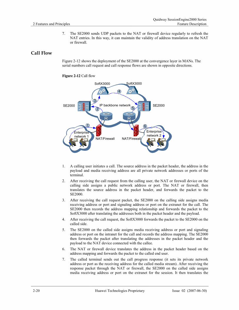
Call Flow
Figure 2-12 shows the deployment of the SE2000 at the convergence layer in MANs. The
serial numbers call request and call response flows are shown in opposite directions.
Figure 2-12 Call flow
SoftX3000
SE2000 SE2000
(1)
NAT/Firewall NAT/Firewall
SoftX3000
2
1
3
4
5
6
IP backbone network
Enterprise
network 1
Enterprise
network 2
1. A calling user initiates a call. The source address in the packet header, the address in the
payload and media receiving address are all private network addresses or ports of the
terminal.
2. After receiving the call request from the calling user, the NAT or firewall device on the
calling side assigns a public network address or port. The NAT or firewall, then
translates the source address in the packet header, and forwards the packet to the
SE2000.
3. After receiving the call request packet, the SE2000 on the calling side assigns media
receiving address or port and signaling address or port on the extranet for the call. The
SE2000 then records the address mapping relationship and forwards the packet to the
SoftX3000 after translating the addresses both in the packet header and the payload.
4. After receiving the call request, the SoftX3000 forwards the packet to the SE2000 on the
called side.
5. The SE2000 on the called side assigns media receiving address or port and signaling
address or port on the intranet for the call and records the address mapping. The SE2000
then forwards the packet after translating the addresses in the packet header and the
payload to the NAT device connected with the callee.
6. The NAT or firewall device translates the address in the packet header based on the
address mapping and forwards the packet to the called end user.
7. The called terminal sends out the call progress response (it sets its private network
address or port as the receiving address for the called media stream). After receiving the
response packet through the NAT or firewall, the SE2000 on the called side assigns
media receiving address or port on the extranet for the session. It then translates the

Quidway SessionEngine2000 Series
Feature Description 2 Features and Principles
Issue 02 (2007-06-30) Huawei Technologies Proprietary 2-21
addresses in the packet header and the payload, and forwards the packet to the
SoftX3000.
8. The SoftX3000 forwards the packet to the SE2000 on the calling side. After receiving it,
the SE2000 assigns media receiving address or port on the intranet for the session. It then
translates the addresses in the packet header and the payload, and then forwards the
packet to the calling terminal.
9. The called terminal sends out the call success response with similar flow to the call
progress response (ACK response from the calling terminal is also omitted here for the
same reason).
10. After the call succeeds, media stream begins to interact between the calling and called
terminals. Before the interaction begins, the SE2000 media proxy is complete. For
details, see Media Processing Flow.
11. After the session is finished, the calling or called side initiates a call termination request.
The other side responds to the request through the SE2000. With this, the entire call flow
ends.
Media Processing Flow
Figure 2-13 shows the deployment of the SE2000 at the convergence layer in MANs. Media
processing flow is shown in Figure 2-13.
Figure 2-13 Media processing flow
SoftX3000
SE2000 SE2000
(1)
NAT/Firewall NAT/Firewall
SoftX3000
IP backbone network
Enterprise
network 1
Enterprise
network 2
Calling side Called side
The SE2000 has sensed the related description about media stream through the processing of
the call signaling processing and generates the description on control policy for the media
stream (such as RTP address or port translation, bandwidth and flow direction) before
transmitting the RTP packet.
The SE2000 performs the following functions for the received RTP stream based on the media
stream control policy:
� Security check
� QoS assurance
� NAT processing

2 Features and Principles
Quidway SessionEngine2000 Series
Feature Description
2-22 Huawei Technologies Proprietary Issue 02 (2007-06-30)
It learns the source address after NAT, translates media destination address, and then forwards
the media stream.
There is no user register flow in the SE2000 networking because it does not directly interact with users.
Other flows are similar to the above description.
2.3.4 Typical Networking Application of the SE2000
For example, there is an organization whose intranet contains multiple IAD devices that
support various signaling protocols, OpenEye, U-Path terminals, telephone terminals and
video terminals. The intranet is connected with the Internet through a firewall (with NAT
function) and a router.
To implement the Next Generation Network (NGN) voice/video services on the original
network, the ISP only needs to add a SE2000 at the egress of the NAT device instead of
modifying the network topology, as shown in Figure 2-14.
Figure 2-14 Typical networking application of the SE2000
SoftX3000
NAT/
Firewall
IAD
Router
SE2000
PC
Internal
networkIP backbonenetwork
Telephone
Connecting with the NAT device and the egress router, the SE2000 is transparently added into
the original network without need of modifying the network topology. The SE2000 provides
the signaling proxy and the media proxy in this NGN application.
When the SE2000 is deployed between a terminal device and the SoftX switch, the proxy of
the SE2000 is the same regardless of the kind of signaling, such as SIP, MGCP, iDo, U-Path,
H.323 or H.248, is processed.
The following section introduces the communication process when the SE2000 provides
SIP/MGCP/H.323 signaling proxy, as shown in Figure 2-15.

Quidway SessionEngine2000 Series
Feature Description 2 Features and Principles
Issue 02 (2007-06-30) Huawei Technologies Proprietary 2-23
Figure 2-15 Communication between the SE2000 and Softx3000
SoftX3000
IAD
SE2000
RTP RTP RTP
SE2000OpenEye OpenEye
SIP/MGCP/H.323
SIP/MGCP/H.323
telephone
H.323
telephoneH.323
Other termial
Signaling Proxy
The SE2000 can be regarded as a Softx3000 system for NGN users because all the register
and call messages are first sent to the SE2000. The messages are forwarded to the Softx3000
system (such as the SoftX3000 of Huawei) after signaling processing through the SE2000.
The SE2000 can also be regarded as a client of the Softx3000 system because the Softx3000
system first sends the response message to the SE2000. The SE2000 then forwards the
message to the end user after signaling processing.
The SE2000 can obtain information such as session address change and bandwidth
requirements by analyzing and processing the signaling. Based on the session status, it
determines whether to allow the media stream to pass through. Thus, it can protect the
network and prevent bandwidth embezzlement.
Media Proxy
All the media streams between intranets and extranets are processed and forwarded through
the SE2000. The SE2000 first checks the validity of a packet, and then defines a media stream
forwarding policy (such as the firewall, QoS and NAT policy) based on the result of signaling
processing.
Regardless of the networking scheme that is applied, the SE2000 can correctly forward the
media stream with the QoS assurance and security control by specifying the destination
address and port for the RTP stream of intranet or extranet users.
The common data stream, such as the one related to the intranet PC in Figure 2-14, is directly forwarded
through the NAT device to the router. This data stream need not pass through the SE2000.
The SE2000 processes and forwards all the call packets and media streams in the specific
direction. It translates the addresses between different networks by re-specifying the
destination address and port for the RTP stream of intranet or extranet users. In this way, the
NAT traversal is carried out.

2 Features and Principles
Quidway SessionEngine2000 Series
Feature Description
2-24 Huawei Technologies Proprietary Issue 02 (2007-06-30)
Different from NAT Application Level Gateway (ALG), the SE2000 applies full proxy mode to
directionally transmit the media stream instead of translating the IP address in the media stream.
Thus, it ensures the system performance and transmission speed of the device.
2.3.5 Classification of Application Modes
Generally, Intranet users access the Internet through the NAT, while home or office users can
access the Internet directly.
Two application modes involved are as follows:
� Single domain mode
� Multi-domain mode
Single Domain Mode
When the SE2000 on the internal network side is not connected with any NAT device, it
works in single domain mode. The single domain mode can be used at home or in the office.
Figure 2-16 shows the typical networking in single domain mode.
Figure 2-16 Typical networking in single domain mode
SoftX3000
IAD
Router
SE2000
PC
IAD
IP network IP backbone
network
Telephone
In the single domain mode, you can access the Internet only by connecting the terminal
telephones or the IAD devices of video terminals to the SE2000.
Multi-Domain Mode
When the SE2000 on the internal network side is connected with a NAT device or with a NAT
device and an IAD simultaneously, it works in the multi-domain mode. The multi-domain
mode can be used in the enterprise after translation.
Figure 2-17 shows the typical networking in multi-domain mode.

Quidway SessionEngine2000 Series
Feature Description 2 Features and Principles
Issue 02 (2007-06-30) Huawei Technologies Proprietary 2-25
Figure 2-17 Typical networking in multi-domain mode
SoftX3000
IAD
Router
SE2000
PC
IAD
NAT/Firewall
Internal
network
IP backbonenetwork
Telephone
In the multi-domain mode, the SE2000 should connect with both the NAT device and the
egress router. It sends a UDP packet to the NAT device regularly to refresh the NAT entries.
Thus, it maintains the address translation relationship.
2.3.6 IP Addresses Related to the SE2000
When the SE2000 operates in the network, the following three important IP addresses are
involved:
� Client Address
� ServerAddress
� SoftXAddress
The IP addresses related to the SE2000 are shown in Figure 2-18.
Figure 2-18 IP addresses related to the SE2000
SoftX3000
IAD
Router
SE2000
PC
NAT/Firewall
ClientAddress ServerAddress
SoftXAddress
Internal
network
IP backbone
network
Telephone
ClientAddress
The SE2000 connects with the Client (such as NAT or IAD device) through an interface and
the address of this interface is called ClientAddress. One or more such interfaces can exist on
a SE2000. Signaling and media stream can have different client addresses.

2 Features and Principles
Quidway SessionEngine2000 Series
Feature Description
2-26 Huawei Technologies Proprietary Issue 02 (2007-06-30)
ServerAddress
The SE2000 connects with the SoftX switch through an interface and the address of this
interface is known as ServerAddress. One or more such interfaces can exist. Signaling and
media stream can have different server addresses.
SoftXAddress
SoftXAddress is the IP address of the SoftX switch connected with the SE2000. The SE2000
can provide proxy services for multiple Softx3000s.
The Client interface and the Server interface of the SE2000 can be identical or different.
If the same physical interface is used, multiple logical sub-interfaces should be configured on this
interface. Some of the logical sub-interfaces are used as the Client interfaces while the others are used as
the Server interfaces. The ClientAddress and the ServerAddress, therefore, have separate IP addresses
even though both use the same physical interface.
For the same ClientAddress, it is recommended to set the same ServerAddress for signaling address map
and media stream address map.
The SE2000 Client interface receives the register and call messages, which are sent to the
SoftX switch through the SE2000 Server interface after signaling processing.
The SE2000 Client interface also receives the client RTP media streams, which are sent to the
called SE2000 or terminal through the SE2000 Server interface after packet processing.
In this way, ClientAddress, ServerAddress and SoftXAddress form the basic interaction path
between the user and the NGN system.
2.3.7 Communication Ports Related to the SE2000
As we know, multiple NAT and IAD devices are attached to the SE2000 and multiple voice or
video terminals are attached to the IADs. The SE2000 should distinguish the session requests
from different users so that each message can be correctly sent back to the terminal. The
triplet address mapping of ClientAddress, ServerAddress and SoftXAddress is not suitable
here because there are not enough IP addresses for sessions and the expected expansion in the
number of users.
However, the multi-port mapping makes it possible to send each message to the terminal
correctly. It maps various sessions to the same server address but with different port numbers.
Therefore, only one ServerAddress is enough.
In addition, well-known ports and dynamic ports must be configured on the SE2000, as
shown in Figure 2-19.

Quidway SessionEngine2000 Series
Feature Description 2 Features and Principles
Issue 02 (2007-06-30) Huawei Technologies Proprietary 2-27
Figure 2-19 Ports related to the SE2000
SoftX3000
IAD
Router
SE2000
PC
NAT/Firewall
Telephone
Internal
network
IP backbone
network
SIP/MGCP/H.323
well-known port
SIP/MGCP/H.323
well-known port
SIP/MGCP/H.323
well-known port
The SE2000 receives the register and call messages through the Client well-known port. After
the signaling processing and selecting a dynamic port of some signaling protocol, it sends the
messages to the well-known port of the SoftX switch through the Server dynamic port.
Similarly, the SE2000 receives the RTP media stream through the Client well-known port.
After the packet processing and selecting a dynamic port of some media stream, the SE2000
sends the media stream to the called SE2000 or terminal through the SE2000 dynamic port.
Client-oriented Well-Known Port on the SE2000
The client-oriented well-known port refers to the well-known port that the SE2000 provides
for the client. Client terminals initiate session connections to the SE2000 through these
well-known ports.
Softx3000-oriented Dynamic Port on the SE2000
The ports include the port ranges used by:
� SIP
� MGCP
� H.323
� iDo
� U-Path
� H.248
� RTP media stream
The port number is automatically assigned by the system. You can specify the port range for
such ports.
Well-Known Port on the Softx3000
The well-known port refers to the communications port on the Softx3000, through which the
SE2000 initiates session connections to the Softx3000. Ensure that the port information on the
SE2000 is identical with that on the Softx3000.
As shown in Figure 2-18 and Figure 2-19, a sextuple composes a complete interaction path
between the user and the NGN system. Such a sextuple includes ClientAddress, well-known

2 Features and Principles
Quidway SessionEngine2000 Series
Feature Description
2-28 Huawei Technologies Proprietary Issue 02 (2007-06-30)
port on the SE2000, ServerAddress, dynamic port on the SE2000, SoftXAddress and
well-known port on the Softswitch.
Configure the IP address of the call entity on the IAD as the ClientAddress of the SE2000.
For the related IAD configuration, refer to "Typical Example for Configuring Signaling Proxy and
Media Proxy" in this chapter.
2.3.8 Media Stream Bypass
If the SE2000 serves as the proxy for all media streams, the two problems that may occur are
as follows:
� It demands the SE2000 device for much higher forwarding performances. The more the
users, the higher the demand for forwarding performance of the SE2000.
� The SE2000 serves as the proxy for all media streams, so media streams occupy a lot of
network bandwidth especially in video applications.
The media stream bypass is required. That is, the media streams are transmitted over IP
networks connected with terminals rather than pass the SE2000, as shown in Figure 2-20.
Figure 2-20 Typical signaling stream and media stream of the SE2000 media stream bypass
process
SE2000Server
Media stream
Signaling stream
IP network IP network
2.3.9 User Roaming Restriction
To control the registration of users, you can permit or deny the registration of users on a
certain network segment. You can bind the IP address with user information on the SE2000.
Based on the binding rules, the SE2000 can determine whether to permit or deny the
registration of a user.

Quidway SessionEngine2000 Series
Feature Description 2 Features and Principles
Issue 02 (2007-06-30) Huawei Technologies Proprietary 2-29
2.4 Address Overlapping
2.4.1 Overview of Address Mapping
With the development of MultiProtocol Label Switching (MPLS) and Virtual Private Network
(VPN), the SE2000, which acts as the key equipment enabling the enterprise users to access
the NGN, is required to meet new requirements.
The IP addresses of users in different VPN or private networks may be the same. The SE2000
as an access device needs to interconnect the VPN or private network and serves as the proxy
for terminal users in the VPN or private network. Therefore, the SE2000 should support the
address mapping and thus it can serve as the proxy for the terminals with the same IP address.
By supporting the address overlapping feature, the SE2000 implements the multi-instance
function. Users in the private networks where addresses overlap can access each other without
network address translation (NAT). Besides, the address overlapping feature allows the
signaling and media streams to traverse the specified VPNs. In this case, the SE2000 acts as a
convergent point of multiple networks. It transmits the signaling, media, and management
packets to the corresponding networks.
2.4.2 Principle of Address Overlapping
The address mapping feature distinguishes the users whose addresses overlap through
isolating interfaces or sub-interfaces into different VPN instances. The IP addresses of users in
different VPNs can be the same. Each VPN has its own routing table and ARP entries. An
SE2000 can be regarded as multiple virtual devices. The interfaces in different VPNs must be
separated by virtual LAN (VLAN). Thus the link layer is separated when the packets are
transmitted between the SE2000 and other devices.
While receiving the packets, the SE2000 tags VLAN IDs on the packets according to the
VPNs to which the interfaces belong. Then the packets are routed and the ARP addressing is
performed based on the VPN IDs. The SE2000 supports address overlapping on the terminal
side or the server side.
2.4.3 Address Overlapping Processing Flow
As a proxy, the SE2300 can be accessed by the users of multiple VPNs. Each VPN has its
own address scheme, and the IP addresses of users in different VPNs may be the same. As
shown in Figure 2-21, the SE2000 is connected to a LAN switch. The diagram shows a
sample of the SE2000 networking. You can deploy the SE2000 according to the actual
networking.

2 Features and Principles
Quidway SessionEngine2000 Series
Feature Description
2-30 Huawei Technologies Proprietary Issue 02 (2007-06-30)
Figure 2-21 Networking diagram of address overlapping
SoftX3000
SE2000
Service
VPN
IADMS
IP
backbone
network
VPN 2VPN 1
192.168.216.1/16
192.168.216.2/16
192.168.216.2/16
Lanswitch
Management
VPN
PE
192.168.216.1/16
Private Network Address Overlapping
The provider edge (PE) tags VLAN IDs, which vary with the VPNs, on the packets and then
sends the packets to the SE2000 through the LAN switch. After receiving the register packets
sent from the terminal, the SE2000 records the IP address, port number and VLAN ID of the
terminal user, by which the SE2000 identifies the terminal.
The Softx3000 sends the register response packets to the SE2000. Then, the SE2000 tags
VLAN IDs on the packets and forwards the packets to the PE. The PE forwards the packets to
the corresponding VPN according to the VLAN IDs, and thus the terminal is registered
successfully. The succeeding call flow is similar.
Softx3000 or IADMS Address Overlapping
The IP addresses on the different Softx3000s or Integrated Access Device Management
System (IADMS) servers may be the same. The Softx3000s or IADMS servers do not send
packets to the SE2000, so the SE200 cannot obtain the VLAN IDs from packets and therefore

Quidway SessionEngine2000 Series
Feature Description 2 Features and Principles
Issue 02 (2007-06-30) Huawei Technologies Proprietary 2-31
it does not know the VPNs to which the Softx3000 or IADMS server belong. In this case, you
should know the VLAN IDs allocated by the PE to the Softx3000 or IADMS server, and then
configure the VLAN IDs on the SE2000. Thus the SE2000 tags the VLAN IDs on the register
packets sent to the Softx3000 and then forwards the packets to the PE. The PE forwards the
packets to the corresponding VPN according to the VLAN IDs. When the SE2000 receives
the packets from the Softx3000, the processing flow is similar.
2.5 UDP Tunnel
2.5.1 Overview of the UDP Tunnel
The firewall and the NAT device are usually deployed at the border of the private network and
the public network. By default, a session can be actively established from the private network
to the public network, but it cannot be done in the reverse direction. Therefore, some NGN
terminals cannot properly develop the services because they cannot actively establish sessions.
For example, in the H.323 terminal, Q.931 signaling and H.245 signaling employ the TCP
protocol, which is directive. Therefore, signaling packets cannot traverse NAT devices from
the public network to the private network to establish TCP connections.
To solve the problem, the SE2000 supports the UDP tunnel that can traverse the NAT device.
First of all, you need to configure the UDP tunnel client in the private network, and
meanwhile configure the UDP tunnel server in the public network. Then you need to establish
a UDP tunnel between the UDP tunnel client and the UDP tunnel server. In this way, the
network topology does not need changing or the terminal does not need configuring afresh.
Even if the sending ports of RTP packets are not consistent with the receiving ports, RTP
packets can still be transmitted through the UDP tunnel. The SE2000 is a learning-oriented
device, which cannot send packets to the receiving port on the terminal in the private network
by traversing the NAT device. The voice or video, however, is directive: one direction is
"speak"; the other direction is "listen". The SE2000 can learn the IP address of the sending
port on the terminal in the private network after NAT translation, but cannot learn the IP
address of the receiving port on the terminal in the private network after NAT translation. In
the "listen" direction, packets are not sent. Most packets on the application layer can traverse
NAT devices through the UDP tunnel.
The SE2000 can serve as both the UDP tunnel server and the UDP tunnel client.
2.5.2 Networking Model
The UDP tunnel client is deployed between the terminal and the firewall/NAT device in the
private network. The SE2000-1 serves as the UDP tunnel client; the SE200-2 serves as the
UDP tunnel server. After the UDP tunnel function is enabled, packets based on all protocols
are processed by the UDP tunnel by default.
Since a fault occurs when H.323 packets traverse the NAT device, H.323 packets are
processed by the UDP tunnel but packets based on other protocols are not processed by the
UDP tunnel. Transported based on TCP, Q.931 and H.245 packets are processed by the UDP
tunnel by default. (Registration, Admission, Status) RAS is based on UDP. The RAS
well-known port number should be configured to the UDP tunnel port number. You can
configure two IP addresses for two mapping groups respectively on the downstream interfaces
of the SE2000-2. H.323 packets use one of the mapping groups. The networking model of the
UDP tunnel is shown in Figure 2-22.

2 Features and Principles
Quidway SessionEngine2000 Series
Feature Description
2-32 Huawei Technologies Proprietary Issue 02 (2007-06-30)
Figure 2-22 Networking model of the UDP tunnel
UDP tunnel
SE2000-2
Terminal
Softx3000
NAT/Firewall
Internal
network
IP
backbone
network
Signaling
Media streamSE2000-1
UDP Tunnel Client
UDP Tunnel Server
(H.323)
Terminal
(SIP)
2.5.3 UDP Tunnel Processing Procedure
If the terminal fails to serve as the UDP tunnel client, another device should be deployed in
the network to serve as the UDP tunnel client. The terminal is registered with the UDP tunnel
client. For the terminal, the UDP tunnel client serves as the Softx3000; for the UDP client, the
UDP tunnel server serves as the Softx3000. The UDP tunnel is established between the UDP
tunnel client and the UDP tunnel server.
While receiving packets from the terminal, the UDP tunnel client checks whether packets
meet the requirements of being processed by the UDP tunnel according to the configuration.
If the requirements are met, the UDP tunnel header with the length of 12 bytes is added to
packets. The structure of the UDP tunnel header is shown in Figure 2-23.
The meaning of the fields of the UDP tunnel header is as follows:
� Source port (two bytes): for the UDP tunnel client, it indicates the port number bound
with the UDP tunnel client; for the UDP tunnel server, it indicates the port number of the
UDP tunnel server configured on the UDP tunnel client.
� Destination port (two bytes): for the UDP tunnel client, it indicates the port number of
the UDP tunnel server configured on the UDP tunnel client; for the UDP tunnel server, it
indicates the port number bound with the UDP tunnel client.
� Length of UDP tunnel packet (two bytes): indicates the length of the UDP tunnel packet.
It consists of the UDP tunnel packet header and user data.
� Checksum (two bytes): indicates the Cyclic Redundancy Check (CRC) checksum of the UDP
tunnel packet.
� Type of the UDP tunnel (one byte): indicates the type of the UDP tunnel. The field is not
used for the time being, but instead it is reserved for expanding the packet header.
� Payload protocol (one byte): indicates the protocol that is run to transport the packet
without adding the UDP tunnel header. The protocol is TCP or UDP.
� Tunnel fragment information (two bytes): indicates the fragment information about the
tunnel packet.

Quidway SessionEngine2000 Series
Feature Description 2 Features and Principles
Issue 02 (2007-06-30) Huawei Technologies Proprietary 2-33
Figure 2-23 UDP tunnel header
Source port
(2 bytes)
Destination
port
(2 bytes)
Length of the
UDP tunnel
packet(2 bytes)
Checksum
(2 bytes)
Type of UDP
tunnel packet
(1byte)
Payload
protocol
(1 byte)
Tunnel fragment
information
(2 bytes)
The UDP tunnel packet is generated through inserting a UDP tunnel header between the IP
header and TCP/UDP header. After passing through the firewall or the NAT device, the UDP
tunnel packet header is changed. The structure of the UDP tunnel packet is shown in Figure
2-24. On receiving a packet, the UDP tunnel server checks whether the packet is a UDP
tunnel packet. If so, the UDP tunnel server removes the UDP tunnel header and then sends the
packet to the Softx3000.
Figure 2-24 UDP tunnel packet structure
Eth
header
IP
header
UDP tunnel
header (12 bytes)Original TCP/UDP
headerData
On receiving a packet returned from the Softx3000, the UDP tunnel server checks whether the
packet is a UDP tunnel packet. If so, the UDP tunnel server inserts a UDP tunnel header after
the IP header. Thus, a UDP tunnel packet is generated. On receiving a packet returned from
the NAT device, the UDP tunnel client checks whether the packet is a UDP tunnel packet. If
so, the UDP tunnel client removes the UDP tunnel header and then sends the packet to the
terminal.
2.6 Large Capacity
2.6.1 Overview of Large Capacity
As a signaling proxy and media proxy device, the SE2000 is targeted for solving problems in
NGN, such as NAT traversal, QoS, and security. Located at the edge of networks, the SE2000
facilitates the access of enterprise users to NGN. For the NGN users, the SE2000 acts as the
Softx3000. Currently, to support large capacity networks, the carriers usually deploy multiple
SE2000s in the networks. As a result, the carrier must configure multiple server addresses for
numbers of terminal users and the workload on maintenance increases tremendously. This
hinders the development of new users.
To solve the problem, a signaling dispatching device (SDD) is required. The SDD acts as a
uniform external interface of a group of SE2000s. All the signaling messages destined for the
SE2000s are sent to the SDD first, and then the SDD dispatches the messages to the
corresponding SE2000 according to the configured policies.
Before dispatching the messages to the SE2000, the SDD checks the capacity of the SE2000.
If the capacity is insufficient, the SDD can discard the messages or send the messages to other
SE2000s. The SDD can forward the succeeding signaling messages to the same SE2000. The
media streams are not sent to the SDD, and instead they are routed to the SE2000s directly.
The SE2300 can serve as the SDD by means of software upgrade; the SE2200 cannot serve as
the SDD.

2 Features and Principles
Quidway SessionEngine2000 Series
Feature Description
2-34 Huawei Technologies Proprietary Issue 02 (2007-06-30)
2.6.2 Networking Model
When the large capacity network is established initially, one SE2000-1 is adequate because
the user quantity is small. (The capacity of one SE2300 is 50000 users; the capacity of one
SE2200 is 10000 users.) As the number of users increases, one SE2000-2 can be added. The
carrier configures signaling dispatching policies on the SDD and then dispatches some of the
signaling messages to the SE2000-2 according to the policies. The advertised client address is
not changed. If the number of users increases continuously, the carrier can add the SE2000-3,
the SE2000-4, and so on. The carrier only needs to modify or add policies on the SDD to
expand the capacity. The capacity expansion is transparent to users, so the configuration on
the terminals is not changed.
The SDD can serve as the SBC. When there are not too many users, the SBC function can be
enabled on the SDD.
Disabling the SBC Function on the SDD
When the SBC function is disabled on the SDD, the SDD is responsible for only dispatching
signaling. The direction of signaling and media stream in the networking is shown in Figure
2-25.
Signaling direction (from the UE to the Softx3000):
UE�NAT�Lanswitch1�SDD�Lanswitch2�SE2000-1�Lanswitch2� Lanswitch1�Softx3000
Signaling direction from the Softsx3000 to the UE is reverse to the above mentioned
direction.
Media stream direction (from the UE to the SE2000-1):
UE�NAT�Lanswitch1�Lanswitch2�SE2000-1
Media stream direction from the SE2000-1 to the UE is reverse to the above mentioned
direction, but media streams do not pass through the SDD or the Softx3000.
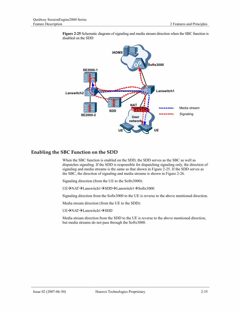
Quidway SessionEngine2000 Series
Feature Description 2 Features and Principles
Issue 02 (2007-06-30) Huawei Technologies Proprietary 2-35
Figure 2-25 Schematic diagram of signaling and media stream direction when the SBC function is
disabled on the SDD
Lanswitch1
SE2000-1
SE2000-2
SDD
用用用用 用用用用户户户户
NAT
Softx3000
IADMS
Signaling
UE
Lanswitch2
User
network
Media stream
UE
Enabling the SBC Function on the SDD
When the SBC function is enabled on the SDD, the SDD serves as the SBC as well as
dispatches signaling. If the SDD is responsible for dispatching signaling only, the direction of
signaling and media streams is the same as that shown in Figure 2-25. If the SDD serves as
the SBC, the direction of signaling and media streams is shown in Figure 2-26.
Signaling direction (from the UE to the Softx3000):
UE�NAT�Lanswitch1�SDD�Lanswitch1�Softx3000
Signaling direction from the Softx3000 to the UE is reverse to the above mentioned direction.
Media stream direction (from the UE to the SDD):
UE�NAT�Lanswitch1�SDD
Media stream direction from the SDD to the UE is reverse to the above mentioned direction,
but media streams do not pass through the Softx3000.

2 Features and Principles
Quidway SessionEngine2000 Series
Feature Description
2-36 Huawei Technologies Proprietary Issue 02 (2007-06-30)
Figure 2-26 Schematic diagram of signaling and media stream direction when the SBC function is
enabled on the SDD
Lanswitch1
SE2000-1
SE2000-2
SDD
User
network
NAT
Softx3000
IADMS
Media stream
Signaling
UE
Lanswitch2
UE
2.6.3 Overview of SDD Dual-System Hot Backup
All the signaling messages are sent to the SDD, so the SDD must be highly reliable. SDD
dual-system hot backup is required to reduce the single point failure.
The networking diagram of SDD dual-system hot backup is shown in Figure 2-27.
The priority of the SDD-1 is higher than that of the SDD-2, so normally the SDD-1 in active
state and the SDD-2 is in standby state. All signaling messages are dispatched to the SDD-1.
The backup entries added to the SDD dual-system hot backup are the resource status table and
the signaling session table.
The SDD supports real-time backup. After receiving the register information from the SBC,
the SDD-1 updates the information in the resource status table and then backs up the resource
status table to the SDD-2. Meanwhile, the SDD-1 backs up the updated signaling session table
to the SDD-2 at intervals.
The SDD also supports manual and automatic batch backup. Manual batch backup is
triggered by the command line; automatic batch backup is automatically triggered when the
master/backup switchover occurs. During batch backup, the SDD-1 backs up all entries (the
resource status table and the signaling session table) to the SDD-2.

Quidway SessionEngine2000 Series
Feature Description 2 Features and Principles
Issue 02 (2007-06-30) Huawei Technologies Proprietary 2-37
Figure 2-27 Networking diagram of SDD hot-system hot backup
Lan
switch1
SE2000-1
SE2000-2
SDD-1
User
network
NAT
Softx3000
IADMS
UE
Lan
switch2
SDD-2
UE
2.7 C-BGF
2.7.1 Overview of C-BGF
The SE2300 supports the C-BGF feature; the SE2200 does not support this feature.
In IMS network, the SE2300 serves as the Core Border Gateway (C-BGF). The SE2300
forwards the SIP signaling packets after NAT to the Proxy-Call Session Control Function
(P-CSCF). In this way, SIP signaling implements NAT through the SE2300.
The SE2300 interacts with the P-CSCF through the SBCI interface to apply for, modify or
release the media resources. Media proxy is thus implemented.
The SE2300 interacts with the Session Policy Decision Function (SPDF) through the Ia
interface to apply for, modify or release resource reservation, as well as release resources in
exceptional cases. QoS control of fixed network terminal access is thus implemented. The
SPDF issues QoS orders to the SE2300 and the SE2300 enforces the task.
In IMS network, the SE2300 supports precise detect of no media stream. The SE2300 sets the
aging time for the RTP session of each user. After both call parties are disconnected, the
SE2300 can precisely detect that no media stream passes through. If no media stream passes
through within the aging time of the RTP session defined by the SE2300, the SE2300 actively
reports the exceptional information about media streams to the P-CSCF through sending the
Common Open Policy Service (COPS) message so that the P-CSCF deletes the session
related to signaling in time.

2 Features and Principles
Quidway SessionEngine2000 Series
Feature Description
2-38 Huawei Technologies Proprietary Issue 02 (2007-06-30)
In IMS network, the SE2300 implements COPS master/backup link switchover, real-time
backup and batch backup of media proxy and session through dual-system hot backup of the
COPS service. When the master SE2300 fails, the backup SE2300 takes over services. Thus,
services are not interrupted, and the demand for reliability of the carrier-level device is met.
2.7.2 Networking Model
Serving as the C-BGF, the SE2300 is located between the terminal and the P-CSCF or the
SPDF. The SE2300 implements the functions of signaling NAT, media stream and QoS
control of fixed network terminal access. The SE2300 interacts with the P-CSCF and the
SPDF through COPS. The terminal interacts with the P-CSCF through Session Initiation
Protocol (SIP). Media streams do not pass through the P-CSCF or the SPDF.
The networking diagram of signaling and media stream in the C-BGF feature is shown in
Figure 2-28.
Figure 2-28 Networking diagram of signaling and media stream in the C-BGF feature
P-CSCF SPDF
BRAS
UE-1 UE-2
BRAS
SE2300
SIP signaling
Media stream
COPS signaling
2.7.3 Implementation Principle of the C-BGF
Signaling NAT
In IMS network, SIP signaling, which is exchanged between the terminal in the private
network and the P-CSCF in the public network, can implement NAT through the SE2300.
When the terminal registers, the P-CSCF delivers the signaling NAT mapping update
messages through the SBCI interface. The P-CSCF thus requests the SE2300 to update the
aging time of the NAT entry as the temporary mapping time of NAT. Meanwhile, the P-CSCF
requests the SE2300 to create the Hello entry and send Hello messages regularly. Thus, the
NAT entry of SIP signaling of the NAT device or the firewall, which is deployed between the
SE2300 and the terminal, can keep alive.

Quidway SessionEngine2000 Series
Feature Description 2 Features and Principles
Issue 02 (2007-06-30) Huawei Technologies Proprietary 2-39
The SE2300 returns the register address of the terminal in the response message to the
P-CSCF. After the terminal registers successfully, the P-CSCF delivers the signaling NAT
mapping update message to request the SE2300 to update the aging time of the NAT entry as
the reregister time of the terminal. When the terminal deregisters, the P-CSCF delivers the
signaling NAT mapping deletion message to the SE2300. The SE2300 then deletes the
signaling NAT entry and the Hello entry.
Media Proxy
In IMS network, the SE2300 interacts with the P-CSCF through the SBCI interface and the
COPS protocol to create, update, query and release the media mapping. Media proxy is thus
implemented.
When the user initiates the call request, the P-CSCF delivers the message in request for
creating the media mapping to the SE2300. The request message contains the media address
and port number of the terminal. After allocating the media address and port number on the
access device side ( the media client side of the BGF mapping group) and on the network side
(the media server side of the BGF mapping group), the SE2300 notifies the P-CSCF and then
the P-CSCF changes the SDP information in the SIP message to the port on the SE2300.
When the P-CSCF obtains the media address and port number of the peer, it delivers the
request message for updating the media stream to the SE2300. The request message contains
the media address and port number of the terminal and the media address and port number of
the peer. The SE2300 then updates the media mapping information and creates the temporary
session table RTP. When the RTP packets are sent from the terminal to the SE2300, the
SE2300 learns the entire session after matching the temporary session entry of RTP based on
the destination address, port number and protocol type. Then the SE2300 forwards media
streams according to the source address, the source port number, the destination address, the
destination port number and the protocol number.
During the call, the SE2300 checks whether the session entry exists regularly; the P-CSCF
delivers the message in request for querying the media mapping regularly. If the session entry
of the SE2300 ages, the aged media mapping information is contained in the response
message.
When the call ends, the P-CSCF delivers the message for deleting the media mapping to the
SE2300. The SE2300 then deletes the media mapping information and the session entry.
QoS Control of Fixed Network Terminal Access
The SE2300 is the sole gate control of user media stream in the fixed network access. In
service request, users apply for a small amount of bandwidth and Access Resource Admission
Control (ARAC) accepts their QoS bandwidth reservation request. In practice, however, users
intend to occupy more bandwidth. The SE2300 can avoid this situation by acting as the gate
control. Even if two user terminals are connected with the SE2300 through the same
Broadband Remote Access Server (BRAS), media steams between the two user terminals
must pass through the SE2300. Thus, media streams are under the control of the SE2300.
When users request services, the SE2300 allocates port numbers under the command of the
P-CSCF and interacts with the SPDF. On receiving the service request message from the
SPDF, the SE2300 searches the call control block (CCB) and the QoS resource status table
according to the flow direction of the media stream contained in the request message and IP
quintuple or triplet (destination address, destination port number and protocol number). Then
the SE2300 judges whether the current resources are adequate.
If the resources are adequate, the P-CSCF changes the SDP information in the SIP message to
the port number of the SE2300 and enables media streams to pass through the SE2300.

2 Features and Principles
Quidway SessionEngine2000 Series
Feature Description
2-40 Huawei Technologies Proprietary Issue 02 (2007-06-30)
Through the Ia interface and running the COPS protocol, the SE2300 sends the policy
installation success or failure message. If the QoS policy is installed successfully and the
status of the gate control is "open", the SE2300 delivers the bandwidth reservation value and
updates the QoS resource status table. If the QoS policy is installed unsuccessfully, the
SE2300 does not reserve the bandwidth.
At the request of QoS control, the SE2300 modifies the reserved resources:
� Adds media streams.
� Modifies the bandwidth of some media streams.
� Modifies the status of media streams.
� Modifies IP quintuple, that is, the source address the source port number, the destination
address, the destination port number and the protocol number.
During an offer and answer process, if the current resources in the access network are
inadequate, the SE2300 fails to modify the resources, such as increase the bandwidth of media
streams or add new media streams. As a result, the SE2300 is still in resource reservation state
instead of releasing the reserved resources.
When receiving the gate control message from the SPDF, the SE2300 configures the session
status to invalid, if the gate control status is "close". The SE2300 configures the session status
to valid, if the gate control status is "open"; in this case, the gate control is enabled and media
streams can be forwarded.
When receiving the message from the SPDF in request for deleting services, the SE2300
sends the QoS policy installation success or failure message to the SPDF. If the QoS policy is
installed successfully, the SE2300 releases QoS resources and updates the QoS resource status
table; if not, the SE2300 does not release QoS resources.
VLAN Address Overlapping
The IP addresses of users in different VPNs can be the same. Serving as the C-BGF, the
SE2300 supports the VLAN address overlapping in IMS. The private networks where IP
addresses overlap can be connected with the SE2300. The SE2300 distinguishes users in
VPNs or private networks through different VLAN IDs and IP addresses.
When the terminal initiates the register request, the P-CSCF delivers the message for updating
the signaling NAT mapping through the SBCI interface. The SE2300 then returns the register
address of the terminal in the response message. If multiple VLANs exist, the register address
of the terminal contains the VLAN ID. After receiving the response packet, the P-CSCF stores
the register address and VLAN ID of the terminal.
When the terminal initiates the call request, the P-CSCF delivers the message in request for
creating the media mapping to the SE2300. The message contains the register address and
VLAN ID of the terminal. The SE2300 then matches the mapping group according to ACL
rules and allocates the media address and port number according to the terminal address and
VLAN ID.
Exception Processing
If the SPDF fails, the SE2300 releases media resources and the P-CSCF releases all signaling
resources. All CCB and session entries are deleted and the resource status table is updated.
If the P-CSCF fails, the SPDF requests the SE2300 to release resources. Meanwhile, CCB and
session entries are deleted and the resource status table is updated.

Quidway SessionEngine2000 Series
Feature Description 2 Features and Principles
Issue 02 (2007-06-30) Huawei Technologies Proprietary 2-41
If the SE2300 fails and thereby all media streams passing through it are interrupted, the
SE2300 sends the service deletion message to the SPDF. Thus, the supported services on the
SE2300 are the same as those on the SPDF. The SPDF informs the P-CSCF of releasing the
calls related to signaling. Meanwhile, CCB and session entries are deleted and the resource
status table is updated.