sba installation and maintenance manual - audiocodes · sba installation and maintenance manual ....
TRANSCRIPT

Version 6.8 April 2016
Document #: LTRT-39164
SBA Installation and Maintenance Manual
Mediant 800B SBA for Microsoft Lync Server
Microsoft® Lync™ Server
Survivable Branch Appliance
Mediant™ 800B SBA


Installation & Maintenance Manual Contents
Version 6.8 3 Microsoft Lync Server
Table of Contents 1 Introduction ....................................................................................................... 15
2 Verifying Package Contents ............................................................................. 19
Hardware Description .............................................................................................21
3 Front Panel ........................................................................................................ 23
3.1 Ports and Buttons ................................................................................................. 23 3.2 LEDs Description .................................................................................................. 25
3.2.1 LAN Interface LEDs .................................................................................................25 3.2.2 FXS LEDs ................................................................................................................25 3.2.3 FXO LEDs ................................................................................................................25 3.2.4 BRI LEDs .................................................................................................................26 3.2.5 E1/T1 LEDs .............................................................................................................26 3.2.6 Operational Status LEDs .........................................................................................27 3.2.7 Power LEDs .............................................................................................................27
4 Rear Panel .......................................................................................................... 29
Setting up the Mediant 800B PSTN Gateway ........................................................31
5 Cabling the Mediant 800B PSTN Gateway ...................................................... 33
5.1 Grounding the Device ........................................................................................... 33 5.2 Connecting to LAN ............................................................................................... 34 5.3 Analog Devices .................................................................................................... 36
5.3.1 Connecting the FXS Interfaces ................................................................................36 5.3.2 Connecting the FXO Interfaces ...............................................................................37 5.3.3 Connecting the FXS Analog Lifeline ........................................................................38
5.4 ISDN BRI Interfaces ............................................................................................. 39 5.4.1 Connecting to BRI Lines ..........................................................................................39 5.4.2 Connecting the PSTN Fallback for BRI Lines .........................................................40
5.5 Connecting to ISDN PRI (E1/T1) Trunks .............................................................. 41 5.6 Connecting to a Computer for Serial Communication ........................................... 42 5.7 Powering up the Device ........................................................................................ 43
6 Preparing PSTN Network Connectivity ........................................................... 45
6.1 Initial Access to the PSTN Gateway ..................................................................... 45 6.2 Changing OAMP Interface .................................................................................... 46 6.3 Configuring Physical Ethernet Ports ..................................................................... 48
Preparing SBA at DataCenter .................................................................................51
7 Adding the SBA Device to the Active Directory ............................................. 53
8 Defining the Branch Office Topology using Topology Builder ..................... 55
8.1 Defining the Branch Office .................................................................................... 56 8.2 Publishing the Topology ....................................................................................... 65
Setting up the SBA Management Interface ...........................................................67

Installation & Maintenance Manual 4 Document #: LTRT-39164
Mediant 800B SBA
9 Initially Connecting to the SBA Management Interface ................................. 69
9.1 Initially Connecting to the SBA Using the Internal NIC .......................................... 69 9.2 Initially Connecting to the SBA Using an External NIC .......................................... 71
10 Installing and Configuring the SBA ................................................................. 73
10.1 Step 1: Define IP Settings..................................................................................... 75 10.2 Step 2: Change Computer Name.......................................................................... 79 10.3 Step 3: Change Admin Password ......................................................................... 82 10.4 Step 4: Set Date and Time ................................................................................... 84 10.5 Step 5: Join to a Domain ...................................................................................... 87 10.6 Step 6: Device Preparation ................................................................................... 90 10.7 Step 7: Cs Database Installation........................................................................... 93 10.8 Step 8: Backup ..................................................................................................... 95 10.9 Step 9: Enable Replication ................................................................................... 97 10.10 Step 10: Activate Lync .......................................................................................... 99 10.11 Step 11: Lync Certificate .................................................................................... 101 10.12 Step 12: Start Lync Services .............................................................................. 107 10.13 Step 13: Configure Gateway and Test Calls ....................................................... 109 10.14 Step 14: Test Lync Calls ..................................................................................... 112
10.14.1 Test Prerequisites ..................................................................................................112 10.14.2 Running the Lync Call Test ...................................................................................113
10.15 Step 15: Apply Security ...................................................................................... 115 10.15.1 Apply No Policy ......................................................................................................115 10.15.2 Apply Default Security Template ...........................................................................117 10.15.3 Apply User-Defined Security Template .................................................................120
10.16 Step 16: (Optional) Remote Control .................................................................... 123 10.17 Step 17 (Optional) SNMP Setup ......................................................................... 125 10.18 Step 18: Completing SBA Setup ......................................................................... 130 10.19 Monitoring and Maintenance Actions .................................................................. 131
10.19.1 Viewing General SBA Status in the Home Page ...................................................131 10.19.2 Starting and Stopping SBA Services .....................................................................132 10.19.3 Viewing Logged Events .........................................................................................134 10.19.4 Logging Out ...........................................................................................................134
Configuring the PSTN Gateway ............................................................................135
11 Configuring the PSTN Gateway ..................................................................... 137
11.1 Configuring the Mediation Server ....................................................................... 138 11.2 Restricting Communication to Mediation Server Only ......................................... 142 11.3 Configuring the SIP Transport Type ................................................................... 143
11.3.1 Configuring TLS .....................................................................................................143 11.3.1.1 Step 1: Enable TLS and Define TLS Port ..............................................143 11.3.1.2 Step 2: Configure the NTP Server .........................................................144 11.3.1.3 Step 3: Configure the DNS Server .........................................................145 11.3.1.4 Step 4: Configure the Gateway Name ...................................................146 11.3.1.5 Step 5: Configure a Certificate ...............................................................147
11.3.2 Configuring TCP Transport Type ...........................................................................153 11.4 Configuring Secure Real-Time Transport Protocol ............................................. 154 11.5 Configuring Voice Coders (with Silence Suppression) ........................................ 155 11.6 Configuring Comfort Noise and Gain Control ...................................................... 156

Installation & Maintenance Manual Contents
Version 6.8 5 Microsoft Lync Server
11.7 Configuring Early Media ..................................................................................... 158 11.8 Configuring FXS Ports and PSTN Trunks ........................................................... 161
11.8.1 Enabling FXS Ports and PSTN Trunks ..................................................................161 11.8.1.1 Configuring the Channel Select Method ................................................162
11.8.2 Configuring IP-to-Trunk Group Routing .................................................................163 11.8.3 Configuring the Trunk ............................................................................................164 11.8.4 Configuring the TDM Bus ......................................................................................166
11.9 Configuring Normalization Rules for E.164 Format for PBX/PSTN Connectivity . 167 11.9.1 Number Normalization Examples ..........................................................................171
11.9.1.1 Modifying E.164 Numbers to PBX / PSTN Format for Outbound Calls .171 11.9.1.2 Modifying PBX, Local, and National Calls to E.164 Format for Inbound Calls 173
11.10 Configuring SRTP Behavior upon Rekey Mode .................................................. 174 11.11 Configuring FXS Port Transfer Behavior ............................................................. 175
Upgrading the SBA Components .........................................................................177
12 Upgrading MSFT and CU System Components ........................................... 179
13 Upgrading the Management Interface ........................................................... 183
14 Upgrading using the SBA ProConnect .......................................................... 187
Upgrading and Recovering the SBA Image .........................................................189
15 Upgrade and Recovery - Introduction ........................................................... 191
16 Prerequisites ................................................................................................... 193
17 Preparing SBA Upgrade and Recovery ......................................................... 195
17.1 Defining Manual or Automatic Start .................................................................... 195 17.2 Running the Process Immediately or Upon User Confirmation ........................... 196 17.3 Checking Disk before Image Burn ...................................................................... 196 17.4 Creating Disk Partitions ...................................................................................... 197 17.5 Enabling SBA Image Burn on Primary Partition .................................................. 197 17.6 Defining Exit Operation upon Process Completion ............................................. 198 17.7 Defining Network Parameters ............................................................................. 199 17.8 Defining the SBA Image File Name .................................................................... 199 17.9 Defining the SBA Image File Source .................................................................. 200
17.9.1 Defining the FTP ....................................................................................................200 17.9.2 Defining the Local Network ....................................................................................201 17.9.3 Defining the Disk On Key.......................................................................................201 17.9.4 Defining the Recovery Partition .............................................................................201
17.10 Defining the MAC Address Prefix ....................................................................... 202
18 SBA Upgrade and Recovery ........................................................................... 203
18.1 Acquiring an IP Address ..................................................................................... 205
Appendices ............................................................................................................209
A SBA Security Default Template ...................................................................... 211
A.1 Server Roles....................................................................................................... 211

Installation & Maintenance Manual 6 Document #: LTRT-39164
Mediant 800B SBA
A.2 Client Features ................................................................................................... 213 A.3 Administration and Other Options ....................................................................... 214 A.4 Services ............................................................................................................. 215 A.5 Windows Update Policy ...................................................................................... 234 A.6 Firewall Rules ..................................................................................................... 234
A.6.1 Default SBA Internal Firewall Rules ......................................................................234 A.6.2 SBA Network Firewall Settings ..............................................................................252
B Running Anti-Virus Software ......................................................................... 255

Installation & Maintenance Manual Contents
Version 6.8 7 Microsoft Lync Server
List of Figures Figure 1-1: SBA Home Page (Additional AudioCodes Applications Link) New SBA Image ..................16 Figure 1-2: SBA Home Page (Additional AudioCodes Applications Link) SBA Upgrade ......................16 Figure 1-3: Typical Branch Office Deployments .....................................................................................17 Figure 1-4: Summary of Steps for Installing and Configuring SBA ........................................................18 Figure 3-1: Mediant 800B Front Panel ...................................................................................................23 Figure 4-1: Rear Panel ...........................................................................................................................29 Figure 5-1: Grounding the Device ..........................................................................................................33 Figure 5-2: LAN Port-Pair Groups and Web Interface String Names ....................................................34 Figure 5-3: Connecting the LAN Ports ...................................................................................................35 Figure 5-4: RJ-11 Connector Pinouts for FXS Interface ........................................................................36 Figure 5-5: Connecting FXS Interfaces ..................................................................................................36 Figure 5-6: RJ-11 Connector Pinouts for FXO Interface ........................................................................37 Figure 5-7: Connecting FXO Interfaces ..................................................................................................37 Figure 5-8: RJ-11 Connector Pinouts for FXS Lifeline ...........................................................................38 Figure 5-9: Cabling FXS Lifeline ............................................................................................................38 Figure 5-10: RJ-45 Connector Pinouts for BRI Ports .............................................................................39 Figure 5-11: Cabling BRI Ports ..............................................................................................................39 Figure 5-12: Cabling (Ports 1 and 2) PSTN Fallback .............................................................................40 Figure 5-13: RJ-48c Connector Pinouts for E1/T1 .................................................................................41 Figure 5-14: Cabling E1/T1 Ports ...........................................................................................................41 Figure 5-15: Orderable RS-232 Cable Adapter ......................................................................................42 Figure 5-16: Cabling Serial Interface (RJ-45) on Mediant 800B ............................................................43 Figure 5-17: Connecting to the Power Supply........................................................................................44 Figure 6-1: Initial Access to the PSTN Gateway ....................................................................................45 Figure 6-2: Login Screen ........................................................................................................................46 Figure 6-3: IP Settings Screen ...............................................................................................................47 Figure 6-4: Maintenance Actions: Reset Gateway .................................................................................47 Figure 6-5: Physical Ports Settings ........................................................................................................48 Figure 7-1: New Object – Computer Dialog Box ....................................................................................53 Figure 7-2: RTCUniversalReadOnlyAdmins ...........................................................................................54 Figure 8-1: Menu Path to Topology Builder Program Lync 2013 ...........................................................56 Figure 8-2: Menu Path to Topology Builder Program Lync 2010 ...........................................................57 Figure 8-3: Topology Builder Lync 2013 ................................................................................................57 Figure 8-4: Topology Builder Lync 2010 ................................................................................................58 Figure 8-5: Lync Server 2013 Topology Builder .....................................................................................58 Figure 8-6: Lync Server 2010 Topology Builder .....................................................................................59 Figure 8-7: Identify the Site ....................................................................................................................60 Figure 8-8: Specify Site Details ..............................................................................................................60 Figure 8-9: New Branch Site Successfully Defined ................................................................................61 Figure 8-10: Define the Survivable Branch Appliance FQDN ................................................................61 Figure 8-11: Select the Front End Pool ..................................................................................................62 Figure 8-12: Select an Edge Server .......................................................................................................62 Figure 8-13: Define the PSTN Gateway-Lync 2013 ...............................................................................63 Figure 8-14: Define the PSTN Gateway-Lync 2010 ..............................................................................63 Figure 8-15: Publish Topology Selection ................................................................................................65 Figure 8-16: Publish the Topology .........................................................................................................65 Figure 8-17: Publish Wizard Complete ...................................................................................................66 Figure 9-1: Connecting to Internal NIC Default IP ..................................................................................70 Figure 9-2: Welcome to SBA Screen .....................................................................................................70 Figure 9-3: Determining NIC...................................................................................................................71 Figure 9-4: Welcome to SBA Screen .....................................................................................................72 Figure 9-5: SBA Home Screen ...............................................................................................................72 Figure 10-1: Setup Tab Displaying Tasks ..............................................................................................74 Figure 10-2: Set IP Configuration Page .................................................................................................75 Figure 10-3: OSN SBA Server ...............................................................................................................76 Figure 10-4: IP Settings – Login Again ...................................................................................................76 Figure 10-5: IP Settings - Complete .......................................................................................................78

Installation & Maintenance Manual 8 Document #: LTRT-39164
Mediant 800B SBA
Figure 10-6: Change Computer Name Screen.......................................................................................79 Figure 10-7: Reboot Computer after Computer Name Change .............................................................80 Figure 10-8: Server Re-booting ..............................................................................................................80 Figure 10-9: Login Screen ......................................................................................................................81 Figure 10-10: Change Computer Name – Completed Successfully ......................................................81 Figure 10-11: Change Admin Password Screen ....................................................................................82 Figure 10-12: Change Admin Password – Applied Changes .................................................................82 Figure 10-13: Change Admin Password – Completed Successfully ......................................................83 Figure 10-14: Set Date and Time Screen ...............................................................................................84 Figure 10-15: Set Date and Time - Time Zone.......................................................................................84 Figure 10-16: Set Date and Time – Notification Message .....................................................................85 Figure 10-17: Set Date and Time – Applied Changes ...........................................................................85 Figure 10-18: Set Date and Time - Completed Successfully .................................................................86 Figure 10-19: Join to a Domain Screen ..................................................................................................87 Figure 10-20: Domain Details .................................................................................................................87 Figure 10-21: Join to a Domain – Reboot Message Box .......................................................................88 Figure 10-22: Server Rebooting .............................................................................................................88 Figure 10-23: Welcome to SBA ..............................................................................................................89 Figure 10-24: Join to a Domain - Completed Successfully ....................................................................89 Figure 10-25: Device Preparation Screen ..............................................................................................90 Figure 10-26: Device Preparation - Started ............................................................................................91 Figure 10-27: Device Preparation – All Components Installed ..............................................................91 Figure 10-28: Device Preparation – Reboot Message Box ....................................................................92 Figure 10-29: Device Preparation – Completed Successfully ................................................................92 Figure 10-30: Cs Database installation Screen ......................................................................................93 Figure 10-31: Cs Database Installation – Applied Successfully .............................................................94 Figure 10-32: Cs Database–Completed Successfully ............................................................................94 Figure 10-33: Backup Screen .................................................................................................................95 Figure 10-34: Backup – Applied Successfully ........................................................................................95 Figure 10-35: Backup – Completed Successfully ..................................................................................96 Figure 10-36: Enable Replication Screen ...............................................................................................97 Figure 10-37: Enable Replication – Applied Successfully ......................................................................97 Figure 10-38: Enable Replication – Completed Successfully ................................................................98 Figure 10-39: Activate Lync Screen .......................................................................................................99 Figure 10-40: Activate Lync – Applied Successfully ..............................................................................99 Figure 10-41: Activate Lync – Completed Successfully .......................................................................100 Figure 10-42: Lync Certificate Screen ..................................................................................................101 Figure 10-43: Request Certificate ........................................................................................................102 Figure 10-44: Lync Certificate – Detailed Log ......................................................................................103 Figure 10-45: Lync Certificate – Download Enrolled Certificate ...........................................................103 Figure 10-46: Lync Certificate – Download Enrolled Certificate ...........................................................104 Figure 10-47: Lync Certificate – File Download ...................................................................................104 Figure 10-48: Lync Certificate – File Upload ........................................................................................105 Figure 10-49: Lync Certificate – Detail Log ..........................................................................................105 Figure 10-50: Lync Certificate – Complete ...........................................................................................106 Figure 10-51: Start Lync Services Screen ............................................................................................107 Figure 10-52: Lync Services Started ....................................................................................................107 Figure 10-53: Start Lync Services – Completed Successfully .............................................................108 Figure 10-54: Gateway and Endpoint Configuration ............................................................................109 Figure 10-55: Enabling Telnet ..............................................................................................................110 Figure 10-56: Test Call in Progress ......................................................................................................111 Figure 10-57: Test Call Succeeded ......................................................................................................111 Figure 10-58: Gateway Configuration Completed Successfully ...........................................................112 Figure 10-59: Lync Test Call Screen ....................................................................................................113 Figure 10-60: Lync Test Call – Logged Call Test Result ......................................................................113 Figure 10-61: Lync Test Call Completed Successfully .........................................................................114 Figure 10-62: Apply Security-No Policy ................................................................................................115 Figure 10-63: Confirmation-Security Policy Setup Skipped .................................................................116 Figure 10-64: Apply Security Policy- Use Default Template ................................................................117

Installation & Maintenance Manual Contents
Version 6.8 9 Microsoft Lync Server
Figure 10-65: System Logout-Default Security Template Applied .......................................................118 Figure 10-66: System Logout-Security Template .................................................................................118 Figure 10-67: Security Template Successfully Applied ........................................................................119 Figure 10-68: Apply Security Policy- Upload a Security Template.......................................................120 Figure 10-69: Apply Security Policy- Browse to Security Template .....................................................120 Figure 10-70: System Logout-Custom Security Template Applied ......................................................121 Figure 10-71: System Logout-Security Template .................................................................................121 Figure 10-72: Custom Security Template Successfully Applied ..........................................................122 Figure 10-73: Remote Control ..............................................................................................................123 Figure 10-74: Remote Desktop Disabled and Remote Powershell Enabled .......................................124 Figure 10-75: SNMP Setup Screen ......................................................................................................125 Figure 10-76: SNMP Setup-Restart Confirmation ................................................................................126 Figure 10-77: SNMP Setup after Restart .............................................................................................126 Figure 10-78: SNMP Service Started ...................................................................................................127 Figure 10-79: SNMP Service Confirmation ..........................................................................................127 Figure 10-80: SNMP Service is not Installed ........................................................................................128 Figure 10-81: SNMP Service Install Confirmation ................................................................................128 Figure 10-82: SNMP Setup ..................................................................................................................129 Figure 10-83: Complete Setup Screen .................................................................................................130 Figure 10-84: Complete Setup – Setup Completed .............................................................................130 Figure 10-85: Complete Setup – Completed Successfully ...................................................................131 Figure 10-86: Home Page ....................................................................................................................132 Figure 10-87: Start and Stop Service Page ..........................................................................................133 Figure 10-88: Logs Screen Displaying Logged Events ........................................................................134 Figure 10-89: Detailed Log Display ......................................................................................................134 Figure 11-1: Proxy & Registration Page ...............................................................................................138 Figure 11-2: Proxy Sets Table Page ....................................................................................................139 Figure 11-3: Reasons for Alternative Routing Page .............................................................................140 Figure 11-4: SIP General Parameters Page ........................................................................................141 Figure 11-5: Advanced Parameters Page ............................................................................................142 Figure 11-6: SIP General Parameters Page ........................................................................................143 Figure 11-7: Application Settings Page ................................................................................................144 Figure 11-8: DNS Server Settings ........................................................................................................145 Figure 11-9: Proxy & Registration Page ...............................................................................................146 Figure 11-10: Configuring TLS version 1.0 ..........................................................................................147 Figure 11-11: Certificate Signing Request – Creating CSR .................................................................148 Figure 11-12: Microsoft Certificate Services Web Page ......................................................................148 Figure 11-13: Request a Certificate Page ............................................................................................149 Figure 11-14: Advanced Certificate Request Page ..............................................................................149 Figure 11-15: Submit a Certificate Request or Renewal Request Page ..............................................150 Figure 11-16: Certificate Issued Page ..................................................................................................150 Figure 11-17: Download a CA Certificate, Certificate Chain, or CRL Page .........................................151 Figure 11-18: Upload Device Certificate Files from your Computer Group .........................................151 Figure 11-19: Importing Root Certificate into Trusted Certificates Store .............................................152 Figure 11-20: SIP General Parameters Page ......................................................................................153 Figure 11-21: Media Security Page ......................................................................................................154 Figure 11-22: Coders Table Page ........................................................................................................155 Figure 11-23: RTP/RTCP Settings Page ..............................................................................................156 Figure 11-24: IPMedia Settings Page ..................................................................................................157 Figure 11-25: SIP General Parameters Page (1) .................................................................................158 Figure 11-26: SIP General Parameters Page (2) .................................................................................159 Figure 11-27: Advanced Parameters Page ..........................................................................................160 Figure 11-28: Trunk Group Table Page ...............................................................................................161 Figure 11-29: Trunk Group Setting Page .............................................................................................162 Figure 11-30: Inbound IP Routing Table Page .....................................................................................163 Figure 11-31: Trunk Settings Page ......................................................................................................164 Figure 11-32: TDM Bus Settings Page .................................................................................................166 Figure 11-33: Number Manipulation Table - Add Dialog Box ...............................................................167 Figure 11-34: Destination Phone Number Manipulation Table for IPTel Calls .................................172

Installation & Maintenance Manual 10 Document #: LTRT-39164
Mediant 800B SBA
Figure 11-35: Destination Phone Number Manipulation Table for TelIP Calls .................................173 Figure 11-36: AdminPage.....................................................................................................................174 Figure 11-37: Enable Call Transfer Using Re-invites ...........................................................................175 11-38: IP Media Settings ......................................................................................................................176 Figure 12-1: Tools System Update Menu .............................................................................................179 Figure 12-2:System Update Screen .....................................................................................................180 Figure 12-3: System Update Message-Microsoft System Components ..............................................180 Figure 12-4: Login Screen after Automatic Log Out .............................................................................181 Figure 13-1: Tools System Update Menu .............................................................................................183 Figure 13-2:System Update Screen .....................................................................................................184 Figure 13-3: System Update Message-SBA Management Interface Version ......................................184 Figure 13-4: Login Screen after Automatic Log Out .............................................................................185 Figure 15-1: Summary of Steps for SBA Upgrade and Recovery ........................................................191 Figure 16-1: Upgrade and Recovery USB Dongle ...............................................................................193 Figure 18-1: Plugging OSN Server Accessories ..................................................................................204 Figure 18-2: Online Monitoring Using VGA ..........................................................................................204 Figure 18-3: Determining NIC - Internal ...............................................................................................205 Figure 18-4: Connecting Accessories - Internal NIC ............................................................................206 Figure 18-5: Connecting Accessories - External NIC ...........................................................................206 Figure 18-6: Welcome to SBA Screen .................................................................................................207 Figure 18-7: SBA Home Screen ...........................................................................................................207
Installation & Maintenance Manual Contents
Version 6.8 11 Microsoft Lync Server
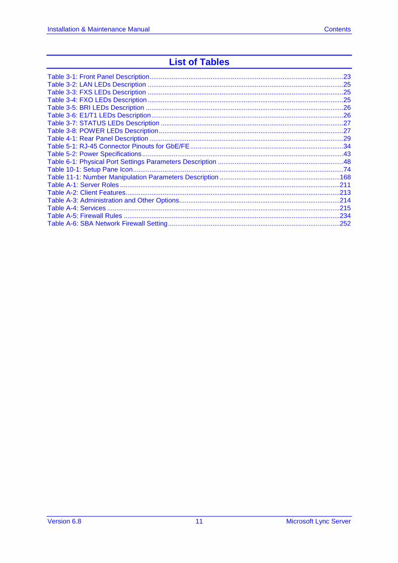
List of Tables Table 3-1: Front Panel Description .........................................................................................................23 Table 3-2: LAN LEDs Description ..........................................................................................................25 Table 3-3: FXS LEDs Description ..........................................................................................................25 Table 3-4: FXO LEDs Description ..........................................................................................................25 Table 3-5: BRI LEDs Description ...........................................................................................................26 Table 3-6: E1/T1 LEDs Description ........................................................................................................26 Table 3-7: STATUS LEDs Description ...................................................................................................27 Table 3-8: POWER LEDs Description ....................................................................................................27 Table 4-1: Rear Panel Description .........................................................................................................29 Table 5-1: RJ-45 Connector Pinouts for GbE/FE ...................................................................................34 Table 5-2: Power Specifications .............................................................................................................43 Table 6-1: Physical Port Settings Parameters Description ....................................................................48 Table 10-1: Setup Pane Icon ..................................................................................................................74 Table 11-1: Number Manipulation Parameters Description .................................................................168 Table A-1: Server Roles .......................................................................................................................211 Table A-2: Client Features....................................................................................................................213 Table A-3: Administration and Other Options.......................................................................................214 Table A-4: Services ..............................................................................................................................215 Table A-5: Firewall Rules .....................................................................................................................234 Table A-6: SBA Network Firewall Setting .............................................................................................252

Installation & Maintenance Manual 12 Document #: LTRT-39164
Mediant 800B SBA
This page is left intentionally blank.

Installation & Maintenance Manual Notices
Version 6.8 13 Microsoft Lync Server
Notice This document describes how to install and configure the Mediant 800B Survivable Branch Appliance (SBA), located at the remote branch office and deployed in the Microsoft Lync Server 2010 or Microsoft Lync Server 2013 environment. Information contained in this document is believed to be accurate and reliable at the time of printing. However, due to ongoing product improvements and revisions, AudioCodes cannot guarantee the accuracy of printed material after the Date Published nor can it accept responsibility for errors or omissions. Updates to this document and other documents, as well as software files can be viewed by registered customers at http://www.audiocodes.com/downloads.
© Copyright 2016 AudioCodes Ltd. All rights reserved. This document is subject to change without notice.
Date Published: April-27-2016
Trademarks AudioCodes, AC, HD VoIP, HD VoIP Sounds Better, IPmedia, Mediant, MediaPack, What’s Inside Matters, OSN, SmartTAP, VMAS, VoIPerfect, VoIPerfectHD, Your Gateway To VoIP, 3GX, VocaNOM and CloudBond 365 are trademarks or registered trademarks of AudioCodes Limited All other products or trademarks are property of their respective owners. Product specifications are subject to change without notice.
WEEE EU Directive Pursuant to the WEEE EU Directive, electronic and electrical waste must not be disposed of with unsorted waste. Please contact your local recycling authority for disposal of this product.
Customer Support Customer technical support and services are provided by AudioCodes or by an authorized AudioCodes Service Partner. For more information on how to buy technical support for AudioCodes products and for contact information, please visit our Web site at www.audiocodes.com/support.
Documentation Feedback AudioCodes continually strives to produce high quality documentation. If you have any comments (suggestions or errors) regarding this document, please fill out the Documentation Feedback form on our Web site at http://www.audiocodes.com/downloads. Your valuable feedback is highly appreciated.
Abbreviations and Terminology Each abbreviation, unless widely used, is spelled out in full when first used.

Installation & Maintenance Manual 14 Document #: LTRT-39164
Mediant 800B SBA
Related Documentation
Manual Name
Mediant 800B SBA Quick Guide

Installation & Maintenance Manual 1. Introduction
Version 6.8 15 Microsoft Lync Server
1 Introduction This document provides step-by-step instructions on installing and configuring the Survivable Branch Appliance (SBA) application running on AudioCodes Mediant 800B OSN, located at the remote branch office and deployed in the Microsoft Lync Server 2013 or 2010 environments. The Mediant 800B SBA includes an OSN Server platform with Windows Server 2008 R2 operating system and Mediation Server software installation (MSI), and a PSTN gateway, all in a single appliance chassis. In the Lync Server environment, given the centralized deployment model, Unified Communication (UC) users in a remote site are dependent on the servers in the enterprise's data center (typically at headquarters) for their communication, and hence are vulnerable to losing communication capabilities when the WAN is unavailable. Given the always-available expectation for voice, it is imperative that the UC solution continues to provide the ability for branch users to make and receive calls when the WAN from the branch to the primary data center is unavailable. To provide voice services to branch users during a WAN outage, a branch office survivability solution–the Survivable Branch Appliance (SBA) application–is hosted on the OSN Server platform running on AudioCodes Mediant 800B SBA located at the branch office. During a WAN connectivity failure, Mediant 800B SBA maintains call connectivity among Microsoft users located at the branch office–Lync Server clients (for example, Microsoft Lync clients) and devices (for example, IP phones)–and between these users and the public switched telephone network (PSTN). The AudioCodes Mediant 800B gateway can also provide the Lync Server environment with a connection to Analog Devices. The Analog devices are connected to the Mediant 800B Foreign eXchange Station (FXS) port interfaces. This document provides also instructions on how to configure the gateway to use its internal FXS port as Analog Devices.
Note: The new SBA image includes the Fax Server and Auto-Attendant IVR applications with full functionality including a ninety day trial license period for each application. For information on how to install these applications and how to activate the license, refer to the document Fax Server and Auto Attendant IVR Installation Guide (click the link on the SBA Home Page to open this document, see Figure 1-1). For full purchase information, contact your AudioCodes representative.

Installation & Maintenance Manual 16 Document #: LTRT-39164
Mediant 800B SBA
Figure 1-1: SBA Home Page (Additional AudioCodes Applications Link) New SBA Image
Figure 1-2: SBA Home Page (Additional AudioCodes Applications Link) SBA Upgrade

Installation & Maintenance Manual 1. Introduction
Version 6.8 17 Microsoft Lync Server
The figure below illustrates typical SBA branch office deployment scenarios.
Figure 1-3: Typical Branch Office Deployments

Installation & Maintenance Manual 18 Document #: LTRT-39164
Mediant 800B SBA
A summary of the steps required to setup the SBA environment is shown in the figure below:
Figure 1-4: Summary of Steps for Installing and Configuring SBA

Installation & Maintenance Manual 2. Verifying Package Contents
Version 6.8 19 Microsoft Lync Server
2 Verifying Package Contents Ensure that your Mediant 800B SBA package is shipped with the following items: Four anti-slide bumpers for desktop mounting 19-inch rack mounting kit (two flanges and six screws) One AC power cable USB tool for SBA software upgrade and recovery procedure (one for Lync Server
2010 and another for Lync Server 2013) Microsoft Windows 2008 R2 license document (envelope) E1/T1 splitter cable adapter for T1 WAN interface (customer ordered item) Check, retain and process any documents. If any items are missing or damaged, please contact your AudioCodes sales representative.

Installation & Maintenance Manual 20 Document #: LTRT-39164
Mediant 800B SBA
This page is left intentionally blank.

Part I Hardware Description This part provides a hardware description overview of the Mediant 800B SBA device. The Mediant 800B SBA is resident on the Mediant 800B Gateway and E-SBC chassis. The chassis' panels are described as follows: Front Panel - see Section 3 on page 23 Rear Panel - see Section 4 on page 29


Installation & Maintenance Manual 3. Front Panel
Version 6.8 23 Microsoft Lync Server
3 Front Panel The front panel provides the telephony port interfaces, various networking ports, reset pinhole button, and LEDs.
3.1 Ports and Buttons The device's front panel is shown in the figure below and described in the subsequent table.
Figure 3-1: Mediant 800B Front Panel
Note: The figure above is used only as an example. The number and type of port interfaces depends on the ordered model.
Table 3-1: Front Panel Description
Item # Label Description
1 USB/WWAN USB port, used for various functionalities such as saving debug captures to a USB storage device. The number of ports depends on chassis version: • Mediant 800B: 2 USB ports • Mediant 800: 1 USB port
2 RS-232 RS-232 port for serial communication. The type of port connector depends on chassis version: • Mediant 800B: RJ-45 • Mediant 800: 12-pin female LX40-12P Hirose connector
3 POWER / STATUS
LEDs indicating the status of the power and reboot/initialization. For more information, see Section 3.2 on page 25.
Installation & Maintenance Manual 24 Document #: LTRT-39164
Mediant 800B SBA
Item # Label Description
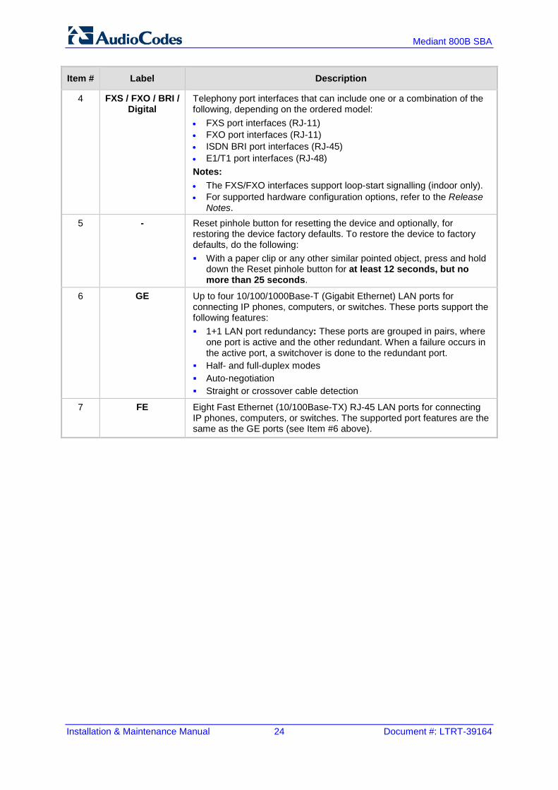
4 FXS / FXO / BRI / Digital
Telephony port interfaces that can include one or a combination of the following, depending on the ordered model: • FXS port interfaces (RJ-11) • FXO port interfaces (RJ-11) • ISDN BRI port interfaces (RJ-45) • E1/T1 port interfaces (RJ-48) Notes: • The FXS/FXO interfaces support loop-start signalling (indoor only). • For supported hardware configuration options, refer to the Release
Notes. 5 - Reset pinhole button for resetting the device and optionally, for
restoring the device factory defaults. To restore the device to factory defaults, do the following: With a paper clip or any other similar pointed object, press and hold
down the Reset pinhole button for at least 12 seconds, but no more than 25 seconds.
6 GE Up to four 10/100/1000Base-T (Gigabit Ethernet) LAN ports for connecting IP phones, computers, or switches. These ports support the following features: 1+1 LAN port redundancy: These ports are grouped in pairs, where
one port is active and the other redundant. When a failure occurs in the active port, a switchover is done to the redundant port.
Half- and full-duplex modes Auto-negotiation Straight or crossover cable detection
7 FE Eight Fast Ethernet (10/100Base-TX) RJ-45 LAN ports for connecting IP phones, computers, or switches. The supported port features are the same as the GE ports (see Item #6 above).

Installation & Maintenance Manual 3. Front Panel
Version 6.8 25 Microsoft Lync Server
3.2 LEDs Description The front panel provides various LEDs depending on the device's hardware configuration (e.g., the available telephony interfaces). These LEDs are described in the subsequent subsections.
3.2.1 LAN Interface LEDs Each LAN port provides a LED (located on its left) for indicating LAN operating status, as described in the table below.
Table 3-2: LAN LEDs Description
LED Color
LED State
Description
Green On Ethernet link established.
Flashing Data is being received or transmitted.
- Off No Ethernet link.
3.2.2 FXS LEDs Each FXS port provides a LED for indicating operating status, as described in the table below.
Table 3-3: FXS LEDs Description
LED Color
LED State
Description
Green On Phone is off-hooked.
Flashing Rings the extension line.
Red On Error - malfunction in line or out of service due to Serial Peripheral Interface (SPI) failure.
- Off Phone is on hook.
- Off No power received by the device.
3.2.3 FXO LEDs Each FXO port provides a LED for indicating operating status, as described in the table below.
Table 3-4: FXO LEDs Description
LED Color
LED State
Description
Green On FXO line is off-hooked toward the PBX.
Flashing Ring signal detected from the PBX.

Installation & Maintenance Manual 26 Document #: LTRT-39164
Mediant 800B SBA
LED Color
LED State
Description
Red On Error - malfunction in line or out of service due to Serial Peripheral Interface (SPI) failure.
- Off Line is on hook.
- Off No power received by the device.
3.2.4 BRI LEDs Each BRI port provides a LED for indicating operating status, as described in the table below:
Table 3-5: BRI LEDs Description
Color State Description
Green On Physical layer (Layer 1) is synchronized (normal operation).
Red On Physical layer (Layer 1) is not synchronized.
- Off Trunk is not active.
3.2.5 E1/T1 LEDs Each trunk port provides a LED for indicating operating status, as described in the table below:
Table 3-6: E1/T1 LEDs Description
Color State Description
Green On Trunk is synchronized (normal operation).
Red On Loss due to any of the following signals: LOS - Loss of Signal LOF - Loss of Frame AIS - Alarm Indication Signal (the Blue Alarm) RAI - Remote Alarm Indication (the Yellow Alarm)
- Off Failure / disruption in the AC power supply or the power is currently not being supplied to the device through the AC power supply entry.

Installation & Maintenance Manual 3. Front Panel
Version 6.8 27 Microsoft Lync Server
3.2.6 Operational Status LEDs The STATUS LED indicates the operating status, as described in the table below.
Table 3-7: STATUS LEDs Description
LED Color
LED State Description
Green On The device is operational and in Stanalone mode (not in High Availability / HA mode)
Flashing The device is rebooting.
Slow Flash HA mode - LED on Active device
Slow/Fast Flash
HA mode - LED on Redundant device
Red On Boot failure.
3.2.7 Power LEDs The POWER LED indicates the operating status, as described in the table below.
Table 3-8: POWER LEDs Description
LED Color
LED State
Description
Green On Power is received by the device.
- Off No power received by the device.

Installation & Maintenance Manual 28 Document #: LTRT-39164
Mediant 800B SBA
This page is left intentionally blank.

Installation & Maintenance Manual 4. Rear Panel
Version 6.8 29 Microsoft Lync Server
4 Rear Panel The device's rear panel is shown in the figure below and described in the subsequent table.
Figure 4-1: Rear Panel
Note: The figure above is used only as an example. Depending on your ordered hardware configuration, the Open Network Solution (OSN) server may provide one or two GE ports.
Table 4-1: Rear Panel Description
Item # Label Description
1 OSN USB Three USB ports (Standard-A type) for connecting computer peripherals (e.g., mouse and keyboard). These are used when implementing the OSN. Note: These ports are available only if the device is equipped with the OSN server (customer ordered).
2 OSN VGA 15-Pin DB-type female VGA port for connecting to a monitor (screen). This port is used when implementing the OSN.
3 - Reset button for resetting the OSN server.
4 GE 1 GE 2
Up to two 10/100/1000Base-T Ethernet ports (RJ-45) (depending on the ordered hardware configuration) for connecting directly to the OSN server.
5
Protective earthing screw.
6 100-240V~1.5A 50-60Hz
3-Prong AC power supply entry.

Installation & Maintenance Manual 30 Document #: LTRT-39164
Mediant 800B SBA
This page is intentionally left blank.
Part II Setting up the Mediant 800B PSTN Gateway This part describes how to cable the Mediant 800B PSTN gateway and how to connect it to the IP network.


Installation & Maintenance Manual 5. Cabling the Mediant 800B PSTN Gateway
Version 6.8 33 Microsoft Lync Server
5 Cabling the Mediant 800B PSTN Gateway This section describes how to connect the Mediant 800B PSTN Gateway: Grounding the Device – see Section 5.1 on page 33 Connecting to the LAN – see Section 5.2 on page 34 Connecting to FXS interfaces – see Section 5.3 on page 36 Connecting to BRI lines – see Section 5.4 on page 39 Connecting to ISDN PRI (E1/T1) Trunks – see Section 5.5 on page 41 Connecting the RS-232 Serial Interface to a Computer – see Section 5.6 on page 42. Powering Up the Device – see Section 5.7 on page 43.
5.1 Grounding the Device The device must be connected to earth (grounded) using an equipment-earthing conductor.
Protective Earthing The equipment is classified as Class I EN60950 and UL60950 and must be earthed at all times. For Finland: "Laite on liltettava suojamaadoituskoskettimilla varustettuun pistorasiaan." For Norway: "Apparatet rna tilkoples jordet stikkontakt." For Sweden: "Apparaten skall anslutas till jordat uttag."
To ground the device:
1. Connect an electrically earthed strap of 16 AWG wire (minimum) to the chassis' grounding screw (located on the rear panel), using the supplied washer.
Figure 5-1: Grounding the Device
2. Connect the other end of the strap to a protective earthing. This should be in accordance with the regulations enforced in the country of installation.

Installation & Maintenance Manual 34 Document #: LTRT-39164
Mediant 800B SBA
5.2 Connecting to LAN The device provides up to four 10/100/1000Base-T (Gigabit Ethernet) RJ-45 ports and up to eight 10/100Base-TX (Fast Ethernet) RJ-45 ports for connection to the LAN. These LAN ports can operate in pairs (groups) to provide LAN port 1+1 redundancy. In each pair, one port serves as the active LAN port while the other as standby. When the active port fails, the device switches to the standby LAN port.
Note: The type and number of Ethernet ports depends on ordered hardware configuration.
The figure below shows the LAN port-pair groups and the name of the ports and groups as displayed in the Web interface for configuring the port groups and assigning them to IP network interfaces (refer to the User's Manual for more information):
Figure 5-2: LAN Port-Pair Groups and Web Interface String Names
These ports support half- and full-duplex modes, auto-negotiation, and straight or crossover cable detection. The RJ-45 connector pinouts are described in the table below:
Table 5-1: RJ-45 Connector Pinouts for GbE/FE
Pin Signal Name
1 Ethernet signal pair (10/100/1000Base-T)
2
3 Ethernet signal pair (10/100/1000Base-T)
6
4 Ethernet signal pair (1000Base-T)
5
7 Ethernet signal pair (1000Base-T)
8
Shield Chassis ground

Installation & Maintenance Manual 5. Cabling the Mediant 800B PSTN Gateway
Version 6.8 35 Microsoft Lync Server
To connect the device to the LAN:
1. Connect one end of a straight-through RJ-45 Cat 5e or Cat 6 cable to the RJ-45 port labeled GE (for Gigabit Ethernet ports) and/or FE (for Fast Ethernet ports).
Figure 5-3: Connecting the LAN Ports
2. Connect the other end of the cable to the Gigabit Ethernet network (for the GE ports) and/or Fast Ethernet network (for the FE ports).
3. For 1+1 LAN protection, repeat steps 1 and 2 for the standby port, but connect it to another network (in the same subnet).
Note: If you are implementing the LAN port-pair redundancy, ensure that the two ports making up a pair are each connected to a different network (in the same subnet).

Installation & Maintenance Manual 36 Document #: LTRT-39164
Mediant 800B SBA
5.3 Analog Devices This section describes how to connect the device to analog equipment.
5.3.1 Connecting the FXS Interfaces The procedure below describes how to cable the device's FXS interfaces.
Warnings: • The device is an INDOOR unit and therefore, must be installed only indoors. • FXS port interface cabling must be routed only indoors and must not exit the building. • Make sure that the FXS ports are connected to the appropriate, external devices;
otherwise, damage to the device may occur. • FXS ports are considered TNV-2.
Notes: • FXS interfaces are a customer-ordered item. • FXS is the interface replacing the Exchange (i.e., the CO or the PBX) and connects
to analog telephones, dial-up modems, and fax machines. The FXS is designed to supply line voltage and ringing current to these telephone devices. An FXS VoIP device interfaces between the analog telephone devices and the Internet.
The RJ-11 connector pinouts used for this connection are shown in the figure below:
Figure 5-4: RJ-11 Connector Pinouts for FXS Interface
To connect the FXS interfaces:
1. Connect one end of an RJ-11 cable to the FXS port (labeled FXS).
Figure 5-5: Connecting FXS Interfaces
2. Connect the other end of the cable to the required telephone interface (e.g., fax machine, dial-up modem, and analog POTS telephone).

Installation & Maintenance Manual 5. Cabling the Mediant 800B PSTN Gateway
Version 6.8 37 Microsoft Lync Server
5.3.2 Connecting the FXO Interfaces The procedure below describes how to cable the device's FXO interfaces.
Warnings: • To protect against electrical shock and fire, use a minimum 26-AWG wire to connect
FXO ports to the PSTN. • Ensure that the FXO ports are connected to the appropriate, external devices;
otherwise, damage to the device may occur. • FXO ports are considered TNV-3.
Notes:
• FXO interfaces are a customer-ordered item. • FXO is the interface replacing the analog telephone and connects to a Public
Switched Telephone Network (PSTN) line from the Central Office (CO) or to a Private Branch Exchange (PBX). The FXO is designed to receive line voltage and ringing current, supplied from the CO or the PBX (similar to an analog telephone). An FXO VoIP device interfaces between the CO/PBX line and the Internet.
The RJ-11 connector pinouts used for this connection are shown in the figure below:
Figure 5-6: RJ-11 Connector Pinouts for FXO Interface
To connect the FXO interfaces:
3. Connect one end of an RJ-11 cable to the FXO port (labeled FXO).
Figure 5-7: Connecting FXO Interfaces
4. Connect the other end of the cable to the required telephone interface: (e.g., telephone exchange analog lines or PBX extensions).

Installation & Maintenance Manual 38 Document #: LTRT-39164
Mediant 800B SBA
5.3.3 Connecting the FXS Analog Lifeline The device's analog Lifeline phone feature redirects IP calls to the PSTN upon a power outage or loss of IP network connectivity, thereby guaranteeing call continuity. The Lifeline is provided by FXS Port # 1. This port connects to the analog POTS phone and the PSTN / PBX using a splitter cable. The Lifeline splitter connects pins 1 and 4 to another source of an FXS port, and pins 2 and 3 to the POTS phone.
Notes:
• Analog Lifeline cabling is applicable only if the device is ordered with FXS interfaces. • The number of supported Lifelines depends on the device’s hardware configuration.
For the combined FXS/FXO configuration, one Lifeline is available; for the 12-FXS configuration, up to three Lifelines are available.
• The scenario upon which the Lifeline is activated is configured by the LifeLineType ini file parameter. For more information, refer to the User's Manual.
The RJ-11 connector pinouts are shown in the figure below.
Figure 5-8: RJ-11 Connector Pinouts for FXS Lifeline
To cable the FXS Lifeline:
1. Connect the Lifeline Splitter (supplied) to FXS Port 1. 2. On the Lifeline splitter cable, do the following:
a. Connect the analog telephone to Port A. b. Connect an analog PSTN line to Port B.
Figure 5-9: Cabling FXS Lifeline

Installation & Maintenance Manual 5. Cabling the Mediant 800B PSTN Gateway
Version 6.8 39 Microsoft Lync Server
5.4 ISDN BRI Interfaces This section describes how to cable the BRI interfaces.
5.4.1 Connecting to BRI Lines The device provides up to four BRI S/T ports. These ports connect to ISDN terminal equipment such as ISDN telephones. Each BRI port can be configured either as termination equipment/user side (TE) or network termination/network side (NT). Up to eight terminal equipment (TE) devices can be connected per BRI S/T port, using an ISDN S-bus that provides eight ISDN ports. When configured as NT, the BRI port drives a nominal voltage of 38 V with limited current supply of up to 100 mA.
Note: BRI interfaces are a customer-ordered item.
The connector pinouts for the BRI port when configured as TE or NT are shown below:
Figure 5-10: RJ-45 Connector Pinouts for BRI Ports
Warning: To protect against electrical shock and fire, use a 26 AWG min wire to connect the BRI ports to the PSTN.
To connect the BRI ports:
1. Connect the BRI cable to the device's BRI RJ-45 port. 2. Connect the other end of the cable to your ISDN telephone or PBX/PSTN switch.
Figure 5-11: Cabling BRI Ports

Installation & Maintenance Manual 40 Document #: LTRT-39164
Mediant 800B SBA
5.4.2 Connecting the PSTN Fallback for BRI Lines The device supports a PSTN Fallback feature for BRI lines, whereby if a power outage or IP connectivity problem (e.g., no ping) occurs, IP calls are re-routed to the PSTN. This guarantees call continuity. PSTN Fallback is supported if the device houses one or more BRI modules, where each BRI module provides two or four spans. In the event of a PSTN fallback, the BRI module's metallic relay switch automatically connects line Port 1 (I) to Port 2 (II) of the BRI module. For example, if a PBX trunk is connected to Port 1 and the PSTN network is connected to Port 2, when PSTN Fallback is activated, calls from the PBX are routed directly to the PSTN through Port 2.
To connect the BRI line interfaces for 1+1 PSTN Fallback:
1. Connect line 1 to a PBX. 2. On the same BRI module, connect line 2 to the PSTN.
Figure 5-12: Cabling (Ports 1 and 2) PSTN Fallback
Notes:
• PSTN Fallback is supported only on BRI interfaces. • PSTN Fallback is supported only between ports on the same BRI module. • The scenarios that trigger PSTN Fallback (i.e., power outage and/or IP network loss)
are configured by the TrunkLifeLineType parameter. For more information, see the User's Manual.
• This PSTN Fallback feature has no relation to the PSTN Fallback Software Upgrade Key.
Installation & Maintenance Manual 5. Cabling the Mediant 800B PSTN Gateway
Version 6.8 41 Microsoft Lync Server
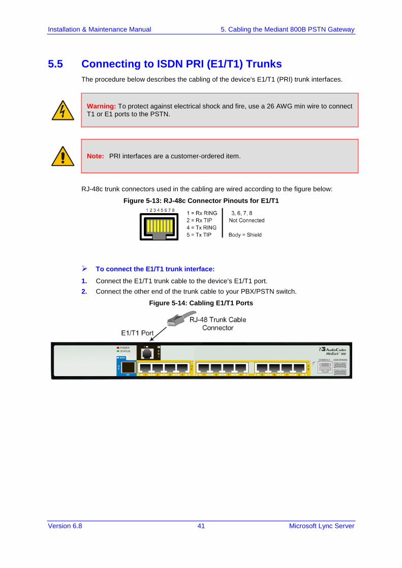
5.5 Connecting to ISDN PRI (E1/T1) Trunks The procedure below describes the cabling of the device's E1/T1 (PRI) trunk interfaces.
Warning: To protect against electrical shock and fire, use a 26 AWG min wire to connect T1 or E1 ports to the PSTN.
Note: PRI interfaces are a customer-ordered item.
RJ-48c trunk connectors used in the cabling are wired according to the figure below:
Figure 5-13: RJ-48c Connector Pinouts for E1/T1
To connect the E1/T1 trunk interface:
1. Connect the E1/T1 trunk cable to the device’s E1/T1 port. 2. Connect the other end of the trunk cable to your PBX/PSTN switch.
Figure 5-14: Cabling E1/T1 Ports

Installation & Maintenance Manual 42 Document #: LTRT-39164
Mediant 800B SBA
5.6 Connecting to a Computer for Serial Communication The device provides an RS-232 serial interface port on its front panel for serial communication with a PC. Mediant 800B:
• Port Type: RJ-45 • Cable: RJ-45 to DB-9
Figure 5-15: Orderable RS-232 Cable Adapter

Installation & Maintenance Manual 5. Cabling the Mediant 800B PSTN Gateway
Version 6.8 43 Microsoft Lync Server
To connect the device's serial interface to a computer:
Mediant 800B: a. Connect the RJ-45 cable connector to the device's serial port, labeled
CONSOLE. b. Connect the other end of the cable to the COM1 or COM2 RS-232
communication port on your PC.
Figure 5-16: Cabling Serial Interface (RJ-45) on Mediant 800B
5.7 Powering up the Device The device receives power from a standard alternating current (AC) electrical outlet. The connection is made using the supplied AC power cord.
Table 5-2: Power Specifications
Physical Specification Value
Input Voltage Single universal AC power supply 100 to 240V
AC Input Frequency 50 to 60 Hz
AC Input Current 1.5A
Warnings:
• The device must be connected to a socket-outlet providing a protective earthing connection.
• Use only the AC power cord that is supplied with the device. • For replacing the power fuse, refer to the Mediant 800 Gateway and E-SBC
Hardware Installation and Maintenance Manual.
To connect the device to the power supply:
1. Connect the line socket of the AC power cord (supplied) to the device's AC power socket (labeled 100-240V 1.5A ~50-60 Hz), located on the rear panel.

Installation & Maintenance Manual 44 Document #: LTRT-39164
Mediant 800B SBA
Figure 5-17: Connecting to the Power Supply
2. Connect the plug at the other end of the AC power cord to a standard electrical outlet. Once you have cabled and powered-up the device, the POWER LED on the front panel lights up green. For a description of this LED, see Section 3.2.7 on page 27.

Installation & Maintenance Manual 6. Preparing PSTN Network Connectivity
Version 6.8 45 Microsoft Lync Server
6 Preparing PSTN Network Connectivity The Mediant 800B SBA includes an embedded Web server (Web interface), providing a user-friendly graphical user interface (GUI) for configuring PSTN gateway-related functionality (PSTN Gateway). The IP address used for accessing this Web interface must be changed to suit the networking scheme in which your Mediant 800B SBA is deployed. Before you can configure the PSTN Gateway, you need to first access it with the default VoIP / Management LAN IP address, as described in Section 6.1 below.
6.1 Initial Access to the PSTN Gateway Before you can configure the PSTN Gateway, you need to access its Web interface using the default VoIP / Management LAN IP address, as described in below.
To initially access the PSTN Gateway:
1. Connect Port 1 (left-most LAN port) located on the front panel directly to the network interface of your computer, using a straight-through Ethernet cable.
Figure 6-1: Initial Access to the PSTN Gateway
2. Change your computer’s IP address so that it is on the same subnet as the default IP address of the Mediant 800B PSTN Gateway (i.e., 192.168.0.2).
3. Open a standard Web browser, and then in the URL address field, enter the Mediant 800B PSTN Gateway default VoIP / Management LAN IP address.

Installation & Maintenance Manual 46 Document #: LTRT-39164
Mediant 800B SBA
4. The following login screen appears, prompting you to log in with your login credentials:
Figure 6-2: Login Screen
5. Log in with the default, case-sensitive user name (“Admin”) and password (“Admin”), and then click OK; the Web interface appears, displaying the Home page.
6. Change your OAMP interface as described in the next section.
6.2 Changing OAMP Interface Once you have accessed your device using the default IP address, you can change your management interface (OAMP) to suit your network environment. Maintain the same cable connection that you used when you initially accessed the device.
To change the OAMP Interface:
1. Modify the device's physical Ethernet port-pair (group) that you wish to assign to the OAMP interface in the Physical Ports Settings page (Configuration tab > VoIP menu > Network > Physical Ports Settings). For more information, see Section 6.3 on page 48.
2. Change the PSTN Gateway's default IP address to correspond with your network addressing scheme and configure the physical LAN port-pair in the Multiple Interface Table page (Configuration tab > VoIP menu > Network > IP Settings), as shown below:
Installation & Maintenance Manual 6. Preparing PSTN Network Connectivity
Version 6.8 47 Microsoft Lync Server
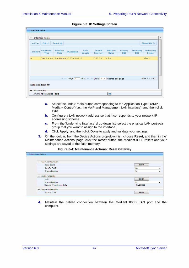
Figure 6-3: IP Settings Screen
a. Select the 'Index' radio button corresponding to the Application Type OAMP + Media + Control"(i.e., the VoIP and Management LAN interface), and then click Edit.
b. Configure a LAN network address so that it corresponds to your network IP addressing scheme.
c. From the 'Underlying Interface' drop-down list, select the physical LAN port-pair group that you want to assign to the interface.
d. Click Apply, and then click Done to apply and validate your settings. 3. On the toolbar, from the Device Actions drop-down list, choose Reset, and then in the‘
Maintenance Actions’ page, click the Reset button; the Mediant 800B resets and your settings are saved to the flash memory.
Figure 6-4: Maintenance Actions: Reset Gateway
4. Maintain the cabled connection between the Mediant 800B LAN port and the computer.

Installation & Maintenance Manual 48 Document #: LTRT-39164
Mediant 800B SBA
6.3 Configuring Physical Ethernet Ports The device's physical Ethernet ports are grouped into pairs (termed Group Members), where each group consists of an active port and a standby port. This provides Ethernet port redundancy within a group, whereby if an active port is disconnected the device switches over to the standby port. These port groups can be assigned to IP network interfaces in the Multiple Interface table. This enables physical separation of network interfaces, providing a higher level of segregation of sub-networks. Equipment connected to different physical ports is not accessible to one another. The only connection between them can be established by cross connecting them with media streams (a VoIP calls). For each Ethernet port, you can configure the speed, duplex mode, native VLAN (PVID), and provide a brief description. Up to six port-pair redundancy groups are supported.
To configure the physical Ethernet ports:
1. Open the Physical Ports Settings page (Configuration tab > VoIP menu > Network submenu > Physical Ports Settings).
Figure 6-5: Physical Ports Settings
2. Select the 'Index' radio button corresponding to the port that you want to configure. 3. Click the Edit button. 4. Configure the ports (see the table below for a description of the parameters). 5. Click Apply.
Table 6-1: Physical Port Settings Parameters Description
Parameter Description
Port (Read-only) Displays the port number. The string values displayed on the Web page represent the physical ports, as shown below:
Mode (Read-only field) Displays the mode of the port: [0] Disable [1] Enable (default)

Installation & Maintenance Manual 6. Preparing PSTN Network Connectivity
Version 6.8 49 Microsoft Lync Server
Parameter Description
Native VLAN
Defines the Native VLAN or PVID of the port. Incoming packets without a VLAN ID are tagged with this VLAN. For outgoing packets, if the VLAN ID as defined in the Multiple Interface table is the same as the Native VLAN ID, the device sends the packet without a VLAN; otherwise, the VLAN ID as defined in the Multiple Interface table takes precedence. The valid value range is 1 to 4096. The default is 1.
Speed & Duplex
Defines the speed and duplex mode of the port. [0] 10BaseT Half Duplex [1] 10BaseT Full Duplex [2] 100BaseT Half Duplex [3] 100BaseT Full Duplex [4] Auto Negotiation (default) [6] 1000BaseT Half Duplex [7] 1000BaseT Full Duplex
Description
Defines an arbitrary description of the port.
Group Member
(Read-only field) Displays the group to which the port belongs.
Group Status
(Read-only) Displays the status of the port: "Active" - the active port "Redundant" - the standby (redundant) port

Installation & Maintenance Manual 50 Document #: LTRT-39164
Mediant 800B SBA
This page is intentionally left blank.

Part III Preparing SBA at DataCenter Prior to installing and configuring the SBA at the branch office you must perform the following at the datacenter (typically, located at headquarters): Add the SBA Device to the Active Directory (AD). See Chapter 7 on page 53. Create a user account on the AD belonging to the RTCUniversalSBATechnicians
group. This user performs the SBA deployment (Domain Admin account can also perform SBA deployment, by default). See Chapter 7 on page 53.
Add (publish) the SBA Device to your topology. See Chapter 8 on page 55.

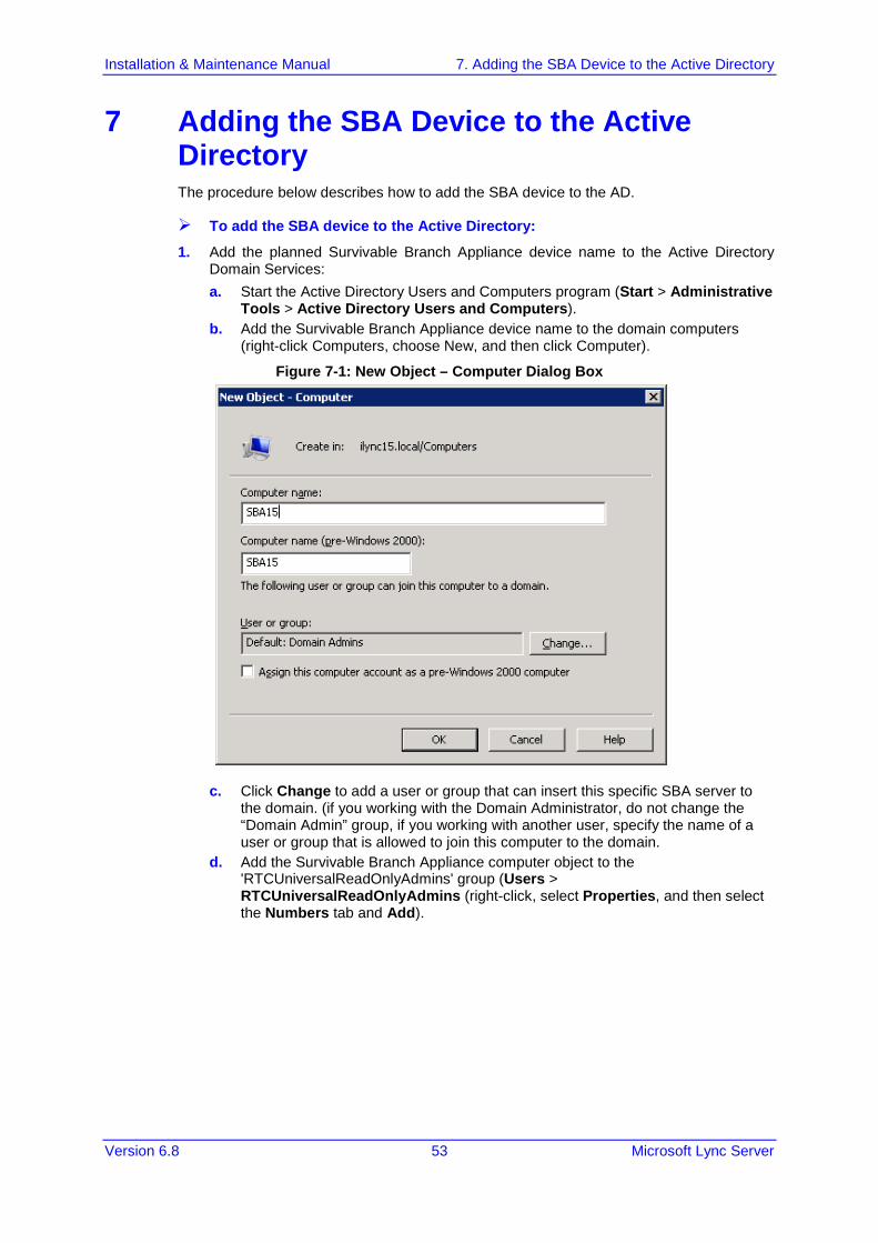
Installation & Maintenance Manual 7. Adding the SBA Device to the Active Directory
Version 6.8 53 Microsoft Lync Server
7 Adding the SBA Device to the Active Directory The procedure below describes how to add the SBA device to the AD.
To add the SBA device to the Active Directory:
1. Add the planned Survivable Branch Appliance device name to the Active Directory Domain Services: a. Start the Active Directory Users and Computers program (Start > Administrative
Tools > Active Directory Users and Computers). b. Add the Survivable Branch Appliance device name to the domain computers
(right-click Computers, choose New, and then click Computer).
Figure 7-1: New Object – Computer Dialog Box
c. Click Change to add a user or group that can insert this specific SBA server to the domain. (if you working with the Domain Administrator, do not change the “Domain Admin” group, if you working with another user, specify the name of a user or group that is allowed to join this computer to the domain.
d. Add the Survivable Branch Appliance computer object to the 'RTCUniversalReadOnlyAdmins' group (Users > RTCUniversalReadOnlyAdmins (right-click, select Properties, and then select the Numbers tab and Add).

Installation & Maintenance Manual 54 Document #: LTRT-39164
Mediant 800B SBA
Figure 7-2: RTCUniversalReadOnlyAdmins
e. Start the ADSI Edit program (Start > Administrative Tools > ADSI Edit). f. Right-click the Survivable Branch Appliance computer name (that you created in
Step 'b' above), and then choose Properties. g. In the Attributes list, set servicePrincipalName to "HOST/<SBA FQDN>", where
SBA FQDN is the FQDN of your Survivable Branch Appliance (e.g., HOST/SBA15.iLync15.local).
2. Create a user account on Active Directory Services belonging to the RTCUniversalSBATechnicians group. This user performs the Survivable Branch Appliance deployment.

Installation & Maintenance Manual 8. Defining the Branch Office Topology using Topology Builder
Version 6.8 55 Microsoft Lync Server
8 Defining the Branch Office Topology using Topology Builder This section describes how to add the Survivable Branch Appliance to your topology, using Lync Server 2013 Topology Builder. This configuration includes the following main steps: Defining the branch office – see Section 8.1 on page 56. Publishing the topology – see Section 8.2 on page 65.
Note: The procedure described in this section is relevant for both Lync 2010 and Lync 2013. Where relevant different screen examples are shown for each deployment.

Installation & Maintenance Manual 56 Document #: LTRT-39164
Mediant 800B SBA
8.1 Defining the Branch Office The procedure below describes how to create and define the branch office.
To create branch sites:
1. Start the Lync Server 2013 Topology Builder program: a. (Start menu > All Programs > Microsoft Lync Server 2013, Lync Server
Topology Builder) or
b. (Start menu > All Programs > Microsoft Lync Server 2010, Lync Server Topology Builder), as shown in the examples below:
Figure 8-1: Menu Path to Topology Builder Program Lync 2013

Installation & Maintenance Manual 8. Defining the Branch Office Topology using Topology Builder
Version 6.8 57 Microsoft Lync Server
Figure 8-2: Menu Path to Topology Builder Program Lync 2010
The Topology Builder opens as shown in the examples below:
Figure 8-3: Topology Builder Lync 2013

Installation & Maintenance Manual 58 Document #: LTRT-39164
Mediant 800B SBA
Figure 8-4: Topology Builder Lync 2010
2. Select the Download Topology from existing deployment option (assuming your Lync Server 2013 or Lync Server 2010 deployment already has a topology), and then click OK; a dialog box opens, prompting you to save the existing topology file.
3. Save the topology; the following example screens appears:
Figure 8-5: Lync Server 2013 Topology Builder

Installation & Maintenance Manual 8. Defining the Branch Office Topology using Topology Builder
Version 6.8 59 Microsoft Lync Server
Figure 8-6: Lync Server 2010 Topology Builder
4. From the Topology Builder console tree, do one of the following: • If you used the Planning tool to design your Enterprise Voice topology, expand
the Branch sites node, and then expand the name of the branch site you specified in the tool. To modify each section of the branch office, right-click the branch site, and then from the shortcut menu, choose Edit Properties.
• If you did not use the Planning tool, right-click the Branch sites node, and then from the shortcut menu, choose New Branch Site; the following dialog box appears:

Installation & Maintenance Manual 60 Document #: LTRT-39164
Mediant 800B SBA
Figure 8-7: Identify the Site
5. In the dialog box, do the following: a. In the ‘Name’ field, type the name of the branch site. Only this field is required,
the other fields are optional. b. In the ‘Description’ field, type a meaningful description of the branch site. c. Click Next; the following dialog box appears:
Figure 8-8: Specify Site Details

Installation & Maintenance Manual 8. Defining the Branch Office Topology using Topology Builder
Version 6.8 61 Microsoft Lync Server
6. In the dialog box, do the following: a. In the ‘City’ field, type the name of the city in which the branch site is located. b. In the ‘State/Province’ field, type the name of the state or region in which the
branch site is located. c. In the ‘Country/Region Code’ field, type the two-digit calling code for the country
in which the branch site is located. d. Click Next; the following dialog box appears:
Figure 8-9: New Branch Site Successfully Defined
7. Select the check box 'Open the New Survivable Branch Appliance Wizard when this wizard closes', and then click Finish; the following dialog box appears:
Figure 8-10: Define the Survivable Branch Appliance FQDN

Installation & Maintenance Manual 62 Document #: LTRT-39164
Mediant 800B SBA
8. In the ‘FQDN’ field, type the FQDN of the SBA, and then click Next.
Note: The Survivable Branch Appliance FQDN that you configured in the ‘FQDN’ field must be the same as the FQDN that you configured using the ADSI Edit program in Chapter 7 on page 53.
The following dialog box appears:
Figure 8-11: Select the Front End Pool
9. From the ‘Front End pool’ drop-down list, select the Front End pool to be used with this SBA, and then click Next; the following dialog box appears:
Figure 8-12: Select an Edge Server

Installation & Maintenance Manual 8. Defining the Branch Office Topology using Topology Builder
Version 6.8 63 Microsoft Lync Server
10. From the ‘Edge pool’ drop-down list, select the Edge pool to be used with this SBA (optional), and then click Next; the following dialog box example screens appear:
Figure 8-13: Define the PSTN Gateway-Lync 2013
Figure 8-14: Define the PSTN Gateway-Lync 2010

Installation & Maintenance Manual 64 Document #: LTRT-39164
Mediant 800B SBA
11. Do the following: a. In the ‘Gateway FQDN or IP Address’ field, type the PSTN Gateway FQDN or IP
address on which the Mediation Server component of the SBA is running. This is the IP address as configured for the PSTN Gateway. If you are using FQDN, ensure that your DNS server is configured to resolve the FQDN into this IP address.
b. In the ‘Listening port for IP/PSTN Gateway’ field, type the Gateway listening port. This must be the same port as configured in the PSTN Gateway, as described in Section 11.3 on page 143.
c. Under the SIP Transport Protocol group, select the SIP Transport Protocol option. This must be the same transport type as configured in the PSTN Gateway, as described in Section 11.3 on page 143.
Note: For call security, it is highly recommended that you deploy a Survivable Branch Appliance using TLS.
d. Click Finish.

Installation & Maintenance Manual 8. Defining the Branch Office Topology using Topology Builder
Version 6.8 65 Microsoft Lync Server
8.2 Publishing the Topology Once you have defined the Branch Office (as described in the previous section), you need to publish this new topology, as described below.
To publish the topology:
1. Right-click the root of the Lync Server 2013 node, and then choose Publish Topology.
Figure 8-15: Publish Topology Selection
The following screen appears:
Figure 8-16: Publish the Topology

Installation & Maintenance Manual 66 Document #: LTRT-39164
Mediant 800B SBA
2. Click Next; the following screen appears:
Figure 8-17: Publish Wizard Complete
3. Verify that all steps display the 'Success' status, and then click Finish.

4
Part IV Setting up the SBA Management Interface This part describes how to connect to the SBA Management interface, and to install and configure the SBA.


Installation & Maintenance Manual 9. Initially Connecting to the SBA Management Interface
Version 6.8 69 Microsoft Lync Server
9 Initially Connecting to the SBA Management Interface The SBA Web-based, graphical user interface (GUI) tool is used for installing and configuring the SBA application running on the Mediant 800B SBA OSN server.
Note: The SBA Management Interface is supported from Internet Explorer 9 and later (Compatibility disabled), Firefox, and Google Chrome.
You can initially connect the SBA to the network using one of the following methods: Using the internal NIC: the SBA is connected to the network through the
gateway/SBC Ethernet port and the devices internal switch. See below. If this option is used, only a single network cable is required (for connecting to the gateway/SBC Ethernet port).
Using the external NIC: the SBA is connected to the network through the GE port on the OSN server. See Section 0 9.2 If this option is used, two network cables are required; one for connecting to the OSN server GE port and the other for connecting to the gateway/SBC application GE port.
9.1 Initially Connecting to the SBA Using the Internal NIC When you initially connect to the SBA using the internal NIC, the network cable should be connected to one of the gateway/SBC GE ports on the device's front panel; this port connects to the device's internal switch, which then connects to the OSN module. The SBA Management interface is initially accessed using the pre-configured factory default IP address of the internal NIC (192.168.0.20/16). You can then change this default IP address using the SBA Management interface to suit your network environment.
Note: This option can be used to initially connect to the SBA server. However, once you are connected to the SBA server, it is recommended to subsequently connect to SBA using an external NIC. This is because when the internal NIC option is used and the gateway/SBC is reset through the device's Web server, then the SBA network connection is lost.
To initially connect to the SBA using the internal NIC:
1. Connect Port 1 (left-most LAN port) located on the front panel directly to the network interface of your computer, using a straight-through Ethernet cable.
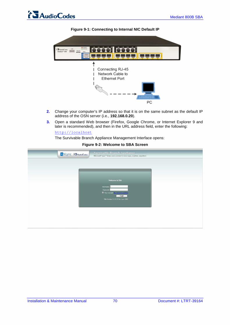
Installation & Maintenance Manual 70 Document #: LTRT-39164
Mediant 800B SBA
Figure 9-1: Connecting to Internal NIC Default IP
2. Change your computer’s IP address so that it is on the same subnet as the default IP address of the OSN server (i.e., 192.168.0.20).
3. Open a standard Web browser (Firefox, Google Chrome, or Internet Explorer 9 and later is recommended), and then in the URL address field, enter the following: http://localhost
The Survivable Branch Appliance Management Interface opens:
Figure 9-2: Welcome to SBA Screen

Installation & Maintenance Manual 9. Initially Connecting to the SBA Management Interface
Version 6.8 71 Microsoft Lync Server
9.2 Initially Connecting to the SBA Using an External NIC When you initially connect to the SBA using the external NIC, the network cable should be connected to one of the GE ports on the OSN module. When this option is used, there is no pre-configured factory default IP address, and therefore the network address must be acquired using DHCP or assigned with a static IP address.
To initially connect to the SBA using the external NIC:
1. Connect one of the OSN server's Ethernet ports (GE1 or GE2) directly to the network using a straight-through Ethernet cable.
2. Plug in the OSN server accessories: a. Connect computer peripherals (e.g., mouse and keyboard) to the USB ports
(Standard-A type) labeled USB. b. Connect the Upgrade and Recovery USB dongle to one of the USB ports, labeled
USB. c. Connect a monitor using a 15-Pin D-type male connector to the VGA female port,
labeled VGA (this VGA cable is not supplied).
Figure 9-3: Determining NIC
3. Determine the NIC used for the Ethernet LAN port, by removing the network cable from the Ethernet port and viewing on the monitor that the NIC (ID) has changed to "Disconnected". This is the NIC corresponding to the external LAN port.
4. Reconnect the network cable. 5. Do one of the following:
• If you have a DHCP server in your network, note the IP address assigned to the Ethernet LAN port .
• If you are not using a DHCP server, then assign a static IP address to the NIC of the Ethernet LAN port.
6. Open a standard Web browser (Firefox, Google Chrome, or Internet Explorer 9 and later is recommended), and then in the URL address field, enter the IP address that you determined above.

Installation & Maintenance Manual 72 Document #: LTRT-39164
Mediant 800B SBA
The Survivable Branch Appliance Management Interface opens:
Figure 9-4: Welcome to SBA Screen
7. Log in with the default username ("Administrator") and password ("Pass123"), Select the “Yes, I accept the term and condition” checkbox and then click Login; the Home screen appears:
Figure 9-5: SBA Home Screen
8. Change the default IP address of the SBA Management Interface to suit your network environment (see Section 10.1 on page 75).

Installation & Maintenance Manual 10. Installing and Configuring the SBA
Version 6.8 73 Microsoft Lync Server
10 Installing and Configuring the SBA Once you are logged in to the SBA Management Interface, you can start configuring SBA, as described in this section. The SBA configuration is done in the Setup tab. For the configuration to be successful, it is imperative that all Setup options are performed correctly and in sequence (according to their order of appearance in the graphical user interface / GUI): 1. Define IP Settings - See Section 10.1 on page 75. 2. Change Computer Name - See Section 10.2 on page 79. 3. Change Admin Password - See Section 10.3 on page 82. 4. Set Date and Time - See Section 10.4 on page 84. 5. Join to a Domain - See Section 10.5 on page 87. 6. Device Preparation - See Section 10.6 on page 90. 7. Cs Database Installation - See Section 10.7 on page 93. 8. Backup - See Section 10.8 on page 95. 9. Enable Replication - See Section 10.9 on page 97. 10. Activate Lync - See Section 10.10 on page 99. 11. Lync Certificate - See Section 10.11 on page 101. 12. Start Lync Services - See Section 10.12 on page 107. 13. Configure Gateway and Test Calls - See Section 10.13 on page 109. 14. Test Lync Calls - See Section 10.14 on page 112. 15. Apply Security - See Section 10.15 on page 115. 16. (Optional) Remote Control - See Section 10.16 on page 123. 17. (Optional) SNMP - See Section 10.17 on page 125. 18. Complete Configuration - See Section 10.18 on page 130. If a task fails, ensure you correct it before performing additional tasks. When a task is configured successfully, a check mark (green) appears alongside the option.
Note: Initially, the Setup menu displays only the first few options (until you Join to a Domain). The remaining options appear only after you successfully Join to the Active Directory Domain.

Installation & Maintenance Manual 74 Document #: LTRT-39164
Mediant 800B SBA
Figure 10-1: Setup Tab Displaying Tasks
In each of the configuration menu screens, the current CPU of the OSN module is displayed in the background. In the Setup pane, a list of all the configurable items is displayed.
Table 10-1: Setup Pane Icon
Setup Pane Icon
Description
Indicates a successfully configured item.
Indicates an item that has not yet been configured.
Indicates an item whose configuration has failed.

Installation & Maintenance Manual 10. Installing and Configuring the SBA
Version 6.8 75 Microsoft Lync Server
10.1 Step 1: Define IP Settings The IP Settings option defines the IP address and domain name server (DNS).
To set the IP address and DNS:
1. Select the Setup tab, and then select the 'IP Settings' check box; a screen similar to the following is displayed:
Figure 10-2: Set IP Configuration Page
2. Clear the 'Enable / Disable NIC' check box for those interfaces that you are not using. 3. From the drop-down list, select one of the following NIC interface options:
• GE1 – Corresponds to one of the GE physical ports on the Mediant 800B rear panel.
• GE2 – Corresponds to one of the GE physical ports on the Mediant 800B rear panel.
• Internal –Internal port that connects to the gateway LAN port on the front panel.
Note: The assignment of the physical ports (Port 1 and Port 2) to the GE1 and GE2 NICs is random.

Installation & Maintenance Manual 76 Document #: LTRT-39164
Mediant 800B SBA
The following screen shows an example of the configured Ethernet ports on the OSN Windows server. In this example, the disabled internal NIC is labeled "Local Area Connection", the disconnected external NIC is labeled "Local Area Connection 2", the disconnected internal NIC is labeled "Local Area Connection 3" and the connected external NIC is labeled "Local Area Connection 4". Note that whenever you connect or disconnect a network cable from one of the interfaces, the status changes.
Figure 10-3: OSN SBA Server
4. Select the "Use following IP" option. 5. Confirm/change the IP address. 6. Confirm/change the IP mask. 7. Confirm/change the default IP gateway. 8. Select the "Use the following DNS address" option. 9. Enter the details of the DNS server. 10. Click Apply. If the IP address has changed and you have logged in as local host, you
will not be required to login again.
Figure 10-4: IP Settings – Login Again

Installation & Maintenance Manual 10. Installing and Configuring the SBA
Version 6.8 77 Microsoft Lync Server
11. Click OK. A new login screen appears. 12. Enter the Username, Password and then click Login.
Notes:
• The system logs in with the new IP address. • Every time you change the NIC interface option, click Apply for the change to take
effect.

Installation & Maintenance Manual 78 Document #: LTRT-39164
Mediant 800B SBA
A green check mark is displayed next to the 'IP Settings' option under the Setup tab, as shown in the figure below.
Figure 10-5: IP Settings - Complete

Installation & Maintenance Manual 10. Installing and Configuring the SBA
Version 6.8 79 Microsoft Lync Server
10.2 Step 2: Change Computer Name The Change Computer Name option defines the computer name of the SBA.
Note:
• This procedure requires you to reboot the SBA server to successfully apply the configuration. However, if you forget to do so, the server automatically reboots after a session timeout. When this occurs, the login screen appears with the following popup message: "The SBA server needs to be rebooted. Please insert your credentials and click Login. The server is then rebooted". After the server reboots, the following message appears: "The SBA server has been rebooted automatically". You can then login to the SBA Management Interface.
• Once you join to the domain, this configuration option is only available when you login as a local user (not a Domain user).
To change the computer name of the SBA server:
1. Select the Setup tab, and then select the 'Change Computer Name' check box; the following screen appears:
Figure 10-6: Change Computer Name Screen
2. In the 'Computer Name' field, enter the computer name.
Note: The Computer Name must be the same as that used for the SBA in the Microsoft Active Directory (AD) and Topology during the pre-configuration steps performed at the datacenter (see Chapter 0 on page 50 and Chapter 8 on page 55).
3. Click Apply; the ''Operation Completed Successfully''message appears on the bottom
of the screen. A message also appears to advise that a re-boot is necessary for the setting to take effect:

Installation & Maintenance Manual 80 Document #: LTRT-39164
Mediant 800B SBA
Figure 10-7: Reboot Computer after Computer Name Change
4. Click Reboot; the SBA server reboots and the following screen is displayed:
Figure 10-8: Server Re-booting
Note: The re-boot process takes approximately five minutes.
When the SBA completes its reboot, the Welcome to SBA screen appears again.

Installation & Maintenance Manual 10. Installing and Configuring the SBA
Version 6.8 81 Microsoft Lync Server
Figure 10-9: Login Screen
5. Enter your username and password and then click Login to log in once again to the SBA Management Interface; the Setup tab appears, displaying a green check mark next to the 'Change Computer Name' option, as shown in the figure below.
Figure 10-10: Change Computer Name – Completed Successfully

Installation & Maintenance Manual 82 Document #: LTRT-39164
Mediant 800B SBA
10.3 Step 3: Change Admin Password The Change Admin Password option resets the local Administrator password.
To change the Administrator password:
1. Select the Setup tab, and then select the 'Change Admin Password' check box; the following screen is displayed:
Figure 10-11: Change Admin Password Screen
2. In the 'Current Password' field, enter the current password. 3. In the 'New Password’ field', enter a new password, and then in the 'Password
Confirm' field, enter the new password again. 4. Click Apply; the following screen appears:
Figure 10-12: Change Admin Password – Applied Changes

Installation & Maintenance Manual 10. Installing and Configuring the SBA
Version 6.8 83 Microsoft Lync Server
5. Click Next to proceed to the next setup task; a green check mark appears next to the 'Change Admin Password' option under the Setup tab, as shown in the figure below.
Figure 10-13: Change Admin Password – Completed Successfully

Installation & Maintenance Manual 84 Document #: LTRT-39164
Mediant 800B SBA
10.4 Step 4: Set Date and Time The Set Date and Time option resets the date and time zone.
To set the date and time:
1. Select the Setup tab, and then select the 'Set Date and Time' check box; the following screen is displayed:
Figure 10-14: Set Date and Time Screen
2. Select the Time Zone tab; the following screen appears:
Figure 10-15: Set Date and Time - Time Zone
3. From the drop-down list, select the appropriate time zone.

Installation & Maintenance Manual 10. Installing and Configuring the SBA
Version 6.8 85 Microsoft Lync Server
4. Select the Date tab, and then define the date and time. 5. Click Apply; the “Operation Completed Successfully” message appears on the bottom
of the screen. 6. Click Apply; a notification message box appears:
Figure 10-16: Set Date and Time – Notification Message
7. Click OK; the following confirmation screen appears:
Figure 10-17: Set Date and Time – Applied Changes
.
8. Click Next to proceed to the next setup task. A green check mark appears next to to the 'Set Date and Time' option under the Setup tab, as shown in the figure below.

Installation & Maintenance Manual 86 Document #: LTRT-39164
Mediant 800B SBA
Figure 10-18: Set Date and Time - Completed Successfully

Installation & Maintenance Manual 10. Installing and Configuring the SBA
Version 6.8 87 Microsoft Lync Server
10.5 Step 5: Join to a Domain The Join to Domain option enables you to join the SBA application to a domain.
Note: This procedure requires you to reboot the SBA server to successfully apply the configuration. However, if you forget to do so, the server automatically reboots after a session timeout. When this occurs, the login screen appears with the following popup message: "The SBA server needs to be rebooted. Please insert your credentials and click Login. The server will then be rebooted". After the server reboots, the following message appears: "The SBA server has been rebooted automatically". You can then login to the SBA Management Interface.
To join the SBA application to a domain:
1. Select the Setup tab, and then select the 'Join to a Domain' check box; the following screen appears:
Figure 10-19: Join to a Domain Screen
Figure 10-20: Domain Details

Installation & Maintenance Manual 88 Document #: LTRT-39164
Mediant 800B SBA
2. In the ‘Domain Name’ field, enter the domain name. 3. In the ‘User’ and ‘Password’ fields, enter the user and password of an account that
has permission to join the SBA to the domain as configured in Chapter 9 on page 69. 4. In the ‘Group name’ field, ensure that the RTCUniversalSBATechnicians value is
selected. 5. Click Apply; a message box appears requesting you to confirm reboot:
Figure 10-21: Join to a Domain – Reboot Message Box
6. Click OK and then click Reboot to reboot the OSN server.
Figure 10-22: Server Rebooting

Installation & Maintenance Manual 10. Installing and Configuring the SBA
Version 6.8 89 Microsoft Lync Server
7. When the reboot completes, the Welcome to SBA login screen appears, now displaying a Domain user check box (which is selected by default):
Figure 10-23: Welcome to SBA
8. Log in with the Domain user username and password, and then click Login; a green check mark is displayed next to the 'Join to a Domain' option under the Setup tab, as shown in the figure below. In addition, the Setup tab now displays the remaining menu configuration options.
Figure 10-24: Join to a Domain - Completed Successfully

Installation & Maintenance Manual 90 Document #: LTRT-39164
Mediant 800B SBA
10.6 Step 6: Device Preparation The Device Preparation menu option completes the SQL preparation and installs the Lync Server 2013 components.
Note: This procedure requires you to reboot the SBA server to successfully apply the configuration. However, if you forget to do so, the server automatically reboots after a session timeout. When this occurs, the login screen appears with the following popup message: "The SBA server needs to be rebooted. Please insert your credentials and click Login. The server will then be rebooted". After the server reboots, the following message appears: "The SBA server has been rebooted automatically". You can then login to the SBA Management Interface.
To prepare the device:
1. Select the Setup tab, and then select the 'Device Preparation' check box; the following screen appears:
Figure 10-25: Device Preparation Screen
2. Click Apply; the SQL installation begins, and the following screens appear in sequence as the SQL installation progresses. You can view a detailed log after each installation phase, by clicking the Detailed Log link.
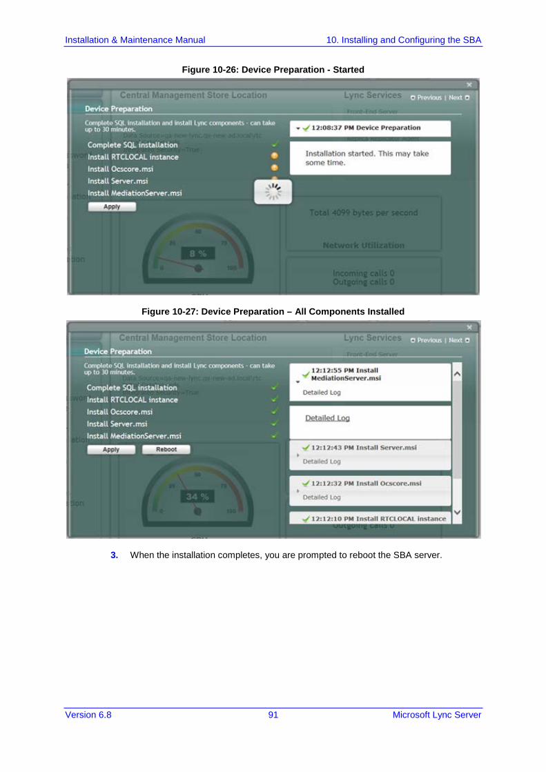
Installation & Maintenance Manual 10. Installing and Configuring the SBA
Version 6.8 91 Microsoft Lync Server
Figure 10-26: Device Preparation - Started
Figure 10-27: Device Preparation – All Components Installed
3. When the installation completes, you are prompted to reboot the SBA server.

Installation & Maintenance Manual 92 Document #: LTRT-39164
Mediant 800B SBA
Figure 10-28: Device Preparation – Reboot Message Box
4. Click OK, and then do one of the following: • If all steps have been completed successfully, click Reboot. • If you wish to review some of the steps, refer to the Detailed Log for corrective
information, rectify the problem, and then click Apply to install the remaining components.
When you relogin to the SBA, a green check mark appears next to the 'Device Preparation' option under the Setup tab, as shown in the figure below.
Figure 10-29: Device Preparation – Completed Successfully

Installation & Maintenance Manual 10. Installing and Configuring the SBA
Version 6.8 93 Microsoft Lync Server
10.7 Step 7: Cs Database Installation The Cs Database installation option installs CsDatabase for Lyss and registrar.
Note: This step is not relevant for Microsoft Lync Server 2010 deployments.
To install the CsDatabase:
1. Select the Setup tab, and then select the 'Cs Database installation' check box; the following screen appears:
Figure 10-30: Cs Database installation Screen

Installation & Maintenance Manual 94 Document #: LTRT-39164
Mediant 800B SBA
2. Click Apply; the following screen appears:
Figure 10-31: Cs Database Installation – Applied Successfully
A green check mark appears next to the 'Cs Database' option under the Setup tab, as shown in the figure below.
Figure 10-32: Cs Database–Completed Successfully

Installation & Maintenance Manual 10. Installing and Configuring the SBA
Version 6.8 95 Microsoft Lync Server
10.8 Step 8: Backup The Backup option creates a backup copy of the Central Management Server on the SBA server.
To create a backup of the Central Management Server:
1. Select the Setup tab, and then select the 'Backup' check box; the following screen appears:
Figure 10-33: Backup Screen
2. Click Apply; the following screen appears:
Figure 10-34: Backup – Applied Successfully

Installation & Maintenance Manual 96 Document #: LTRT-39164
Mediant 800B SBA
A green check mark appears next to the 'Backup' option under the Setup tab, as shown in the figure below.
Figure 10-35: Backup – Completed Successfully

Installation & Maintenance Manual 10. Installing and Configuring the SBA
Version 6.8 97 Microsoft Lync Server
10.9 Step 9: Enable Replication The 'Enable Replication' option enables the replication process with the Central Management Server. The actual replication is executed after all Lync services have been enabled (after Step 12 has been completed - see Section 10.12 on page 107).
To enable replication:
1. Select the Setup tab, and then select the 'Enable Replication' check box; the following screen appears:
Figure 10-36: Enable Replication Screen
2. Click Apply; the following screen appears:
Figure 10-37: Enable Replication – Applied Successfully
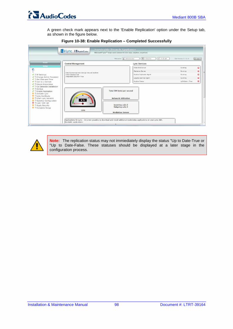
Installation & Maintenance Manual 98 Document #: LTRT-39164
Mediant 800B SBA
A green check mark appears next to the 'Enable Replication' option under the Setup tab, as shown in the figure below.
Figure 10-38: Enable Replication – Completed Successfully
Note: The replication status may not immiediately display the status "Up to Date-True or "Up to Date-False. These statuses should be displayed at a later stage in the configuration process.

Installation & Maintenance Manual 10. Installing and Configuring the SBA
Version 6.8 99 Microsoft Lync Server
10.10 Step 10: Activate Lync The Activate Lync option activates the SBA server machine to run a Lync server 2013 service role. Installing the required software does not automatically cause the SBA server machine to adopt a new service role; instead, it must be activated before it actually begins to function in its new role.
To activate Lync:
1. Select the Setup tab, and then select the 'Activate Lync' check box; the following screen appears:
Figure 10-39: Activate Lync Screen
2. Click Apply; the following screen appears:
Figure 10-40: Activate Lync – Applied Successfully

Installation & Maintenance Manual 100 Document #: LTRT-39164
Mediant 800B SBA
A green check mark appears next to the 'Activate Lync' option under the Setup tab, as shown in the figure below.
Figure 10-41: Activate Lync – Completed Successfully

Installation & Maintenance Manual 10. Installing and Configuring the SBA
Version 6.8 101 Microsoft Lync Server
10.11 Step 11: Lync Certificate The 'Lync Certificate' option installs a certificate from the domain’s certificate authority. This certificate is used to secure the connection between the SBA server and the Central Management Server.
To install a Certificate:
Select the Setup tab, and then select the 'Lync Certificate' check box; the following screen appears:
Figure 10-42: Lync Certificate Screen
Certificates can be installed either by importing an existing certificate or requesting a new certificate.
To import an existing certificate:
1. Select the Import Certification radio button. 2. Click Browse to select the File to Upload. 3. Enter the Password (optional) of the certificates. 4. Click Apply.

Installation & Maintenance Manual 102 Document #: LTRT-39164
Mediant 800B SBA
To request a new certificate:
1. Select the Request Certificate radio button.
Figure 10-43: Request Certificate
2. Requesting a certificate supports Auto-enrollment. Enter all fields. Those fields beginning with a CA prefix are mandatory. The correct Certificate Authority (CA), User and Password must also be supplied. The CA field contains the <CA FQDN>\<CA Name> (e.g., CA.Lync.local\CA-DC-Lync-CA).

Installation & Maintenance Manual 10. Installing and Configuring the SBA
Version 6.8 103 Microsoft Lync Server
Figure 10-44: Lync Certificate – Detailed Log
3. If the CA field is not entered, the system creates an enrollment certificate, which can be downloaded.
Figure 10-45: Lync Certificate – Download Enrolled Certificate
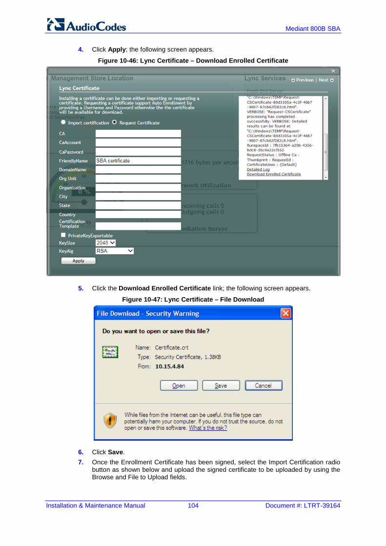
Installation & Maintenance Manual 104 Document #: LTRT-39164
Mediant 800B SBA
4. Click Apply; the following screen appears.
Figure 10-46: Lync Certificate – Download Enrolled Certificate
5. Click the Download Enrolled Certificate link; the following screen appears.
Figure 10-47: Lync Certificate – File Download
6. Click Save. 7. Once the Enrollment Certificate has been signed, select the Import Certification radio
button as shown below and upload the signed certificate to be uploaded by using the Browse and File to Upload fields.

Installation & Maintenance Manual 10. Installing and Configuring the SBA
Version 6.8 105 Microsoft Lync Server
Figure 10-48: Lync Certificate – File Upload
8. Click Apply; the following screen appears:
Figure 10-49: Lync Certificate – Detail Log
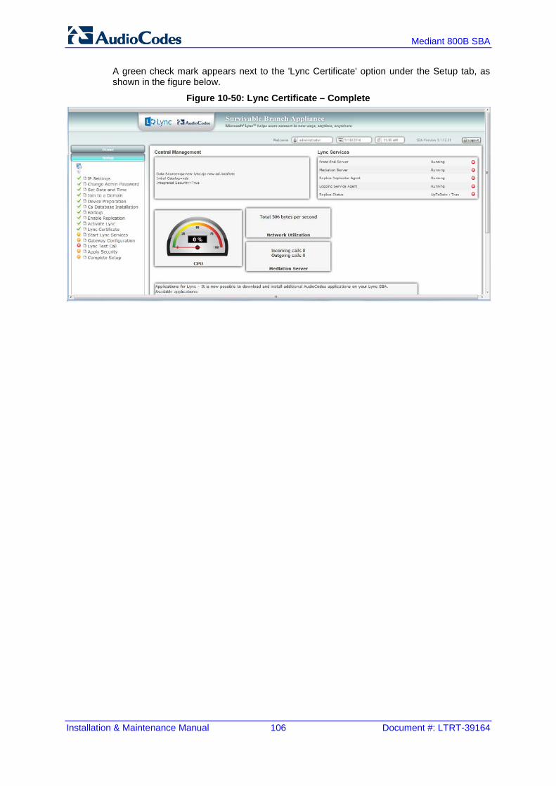
Installation & Maintenance Manual 106 Document #: LTRT-39164
Mediant 800B SBA
A green check mark appears next to the 'Lync Certificate' option under the Setup tab, as shown in the figure below.
Figure 10-50: Lync Certificate – Complete

Installation & Maintenance Manual 10. Installing and Configuring the SBA
Version 6.8 107 Microsoft Lync Server
10.12 Step 12: Start Lync Services The Start Lync Services option enables you to start a Lync Server 2013 (formerly, termed Communications Server) component that runs as a Windows service.
To start Lync services:
1. Select the Setup tab and then select the Start Lync Services check box; the following screen is displayed:
Figure 10-51: Start Lync Services Screen
2. Click Apply to start the services as per the Lync configuration settings; the following screen is displayed:
Figure 10-52: Lync Services Started

Installation & Maintenance Manual 108 Document #: LTRT-39164
Mediant 800B SBA
A green check mark appears next to the 'Start Lync Services' option under the Setup tab, and in the Lync Services information pane all of the Lync Services are shown as "Running" as shown in the figure below.
Figure 10-53: Start Lync Services – Completed Successfully
Note: The Lync Services and Replication Status take time to update and therefore will not immiediately be displayed as running.

Installation & Maintenance Manual 10. Installing and Configuring the SBA
Version 6.8 109 Microsoft Lync Server
10.13 Step 13: Configure Gateway and Test Calls The Gateway Configuration option enables you to connect to the Web-based interface of the PSTN Gateway functionality of the Mediant 800B SBA in order to configure the gateway for testing calls to the PSTN.
Note: Before testing gateway calls:
• Ensure that you have connected the PSTN gateway as described in Chapter 5 on page 33.
• Ensure that you have configured PSTN call routing (for more information, refer to the Mediant 800B MSBR User's Manual).
To configure the gateway and run test calls:
1. Select the Setup tab, and then select the 'Gateway Configuration' check box; the following screen appears:
Figure 10-54: Gateway and Endpoint Configuration
2. In the ‘Gateway’ field, enter the IP address or DNS name of the Mediant 800B. 3. In the 'Phone Number' field, enter the endpoint phone number for which you wish to
test the call. 4. In the ‘DTMF’ field, enter any DTMF string. This DTMF string will be heard when the
user picks up the phone handset (optional). 5. If you changed the Web/Telnet login username and password of the PSTN Gateway,
then enter their values in the ‘Username’ and ‘Password’ fields respectively; otherwise, leave the fields as is.
6. Click Connect; the login screen for the gateway's Embedded HTTP/S-based Web server is displayed.

Installation & Maintenance Manual 110 Document #: LTRT-39164
Mediant 800B SBA
7. Establish a telnet session (enable Telnet on the PSTN Gateway): a. Open the Telnet/SSH Settings page (Configuration tab > System menu >
Management > Telnet/SSH Settings). b. From the ‘Embedded Telnet Server’ drop-down list, select Enable Unsecured. c. In the ‘Telnet Server TCP Port’ field, ensure that the port used for Telnet is '23'
(default).
Figure 10-55: Enabling Telnet
8. Configure PSTN call routing (for more information, refer to the Mediant 800B MSBR User's Manual).

Installation & Maintenance Manual 10. Installing and Configuring the SBA
Version 6.8 111 Microsoft Lync Server
9. In the SBA Management Interface, click Test Call; the test call in progress is displayed:
Figure 10-56: Test Call in Progress
a. When the call has been successfully tested. b. If the phone does not ring, an error message is displayed and the call test fails. If
the phone rings, lift the handset and confirm that you can hear the DTMFs. The following screen appears when you answer the phone:
Figure 10-57: Test Call Succeeded
Note: It is recommended to disable Telnet after making the test call.

Installation & Maintenance Manual 112 Document #: LTRT-39164
Mediant 800B SBA
A green check marks appear next to the 'Gateway Configuration' (and Gateway test call) option under the Setup tab, as shown in the figure below.
Figure 10-58: Gateway Configuration Completed Successfully
10.14 Step 14: Test Lync Calls The Lync Test Call option allows you to test a PSTN call initiated by the Lync Server 2013.
10.14.1 Test Prerequisites Before running the Lync Test Call, the following prerequisites must be met : The gateway call has been successfully tested as described above in Section 10.13
on page 109. Test users have been created in the Lync Server 2013 and are voice-enabled. VoIP Outbound Routing configuration has been setup and the correct policies
assigned to the test users (for more information, refer to the Mediant 800B MSBR User's Manual).
Built-in-users for HealthMonitoring have been configured using the following commands: New-CsHealthMonitoringConfiguration -Identity <XdsGlobalRelativeIdentity> -FirstTestUserSipUri <String> -SecondTestUserSipUri <String>
Where:
• Identity the FQDN of the pool where the health monitoring configuration settings are to be assigned (i.e., SBA FQDN).
• FirstTestUserSipUri is the SIP address of the first test user to be configured for use by this collection of health monitoring settings. Note that the SIP address must include the sip: prefix, for example: -FirstTestUserSipUri sip:[email protected]
• SecondTestUserSipUri is the SIP address of the second test user to be configured for use by this collection of health monitoring settings. Note that the SIP address must include the sip: prefix, for example: -SecondTestUserSipUri sip:[email protected]

Installation & Maintenance Manual 10. Installing and Configuring the SBA
Version 6.8 113 Microsoft Lync Server
10.14.2 Running the Lync Call Test The procedure for running the Lync test call is described below.
To run the Lync test call:
1. Select the Setup tab, and then select the Lync Test Call option; the Lync Test Call screen is displayed:
Figure 10-59: Lync Test Call Screen
2. In the ‘Dial Check Phone Number’ field, enter the PSTN phone number to dial. 3. Click Apply to start the test call. If the test is successful, the phone of the PSTN user rings and when the handset is lifted, the DTMF tones are heard. If the phone does not ring, an error message is displayed on the screen. The screen displays logged details of the call:
Figure 10-60: Lync Test Call – Logged Call Test Result

Installation & Maintenance Manual 114 Document #: LTRT-39164
Mediant 800B SBA
A green check mark appears next to the 'Lync Test Call' option under the Setup tab, as shown in the figure below.
Figure 10-61: Lync Test Call Completed Successfully

Installation & Maintenance Manual 10. Installing and Configuring the SBA
Version 6.8 115 Microsoft Lync Server
10.15 Step 15: Apply Security You can apply a security template to the device. This template configures the security for various SBA services. For example, firewall policy, registries and OS audit policy. You can apply one of the following security policies: No Policy-use a default hardening setup (no security template is loaded to the SBA
device) as was the case until this release. Use default template-Load an AudioCodes built default security template to the SBA
device. Upload a security template-Load an administrator-defined template to the SBA device.
Note: Once a template is loaded, you cannot perform rollback using the SBA GUI. To rollback the security settings, see the Microsoft document at: http://technet.microsoft.com/en-us/library/cc733088.aspx.
10.15.1 Apply No Policy This procedure describes how to configure the 'No Policy' security option on the SBA device. When this option is configured, a default hardening setup is implemented and no security template is loaded to the SBA device.
To implement the No Policy option:
1. Select the Setup tab, and then click the Apply Security option; the following screen is displayed:
Figure 10-62: Apply Security-No Policy

Installation & Maintenance Manual 116 Document #: LTRT-39164
Mediant 800B SBA
2. Select the 'No Policy-skip action' check box option, and then click Apply; the following screen is displayed:
Figure 10-63: Confirmation-Security Policy Setup Skipped

Installation & Maintenance Manual 10. Installing and Configuring the SBA
Version 6.8 117 Microsoft Lync Server
10.15.2 Apply Default Security Template This procedure describes how to apply the default security template.
To apply the default security template:
1. Select the Setup tab, and then click the Apply Security option; the following screen is displayed:
Figure 10-64: Apply Security Policy- Use Default Template

Installation & Maintenance Manual 118 Document #: LTRT-39164
Mediant 800B SBA
2. Select the 'Use default template' check box, and then click Apply; the SBA automatically logs out:
Figure 10-65: System Logout-Default Security Template Applied
3. Click OK for the system to log out while running the security template;the following screen appears:
Figure 10-66: System Logout-Security Template
4. After a few minutes the security setup completes, and the SBA login screen appears.

Installation & Maintenance Manual 10. Installing and Configuring the SBA
Version 6.8 119 Microsoft Lync Server
5. Login and then select the Setup tab. A green check mark appears next to the 'Apply Security' option, as shown in the figure below.
Figure 10-67: Security Template Successfully Applied

Installation & Maintenance Manual 120 Document #: LTRT-39164
Mediant 800B SBA
10.15.3 Apply User-Defined Security Template This procedure describes how to apply a user-defined security template.
To apply a user-defined security template:
1. Select the Setup tab, and then select the 'Apply Security' check box, the following screen is displayed:
Figure 10-68: Apply Security Policy- Upload a Security Template
2. Select the 'Upload a security template' check box; the following screen appears:
Figure 10-69: Apply Security Policy- Browse to Security Template

Installation & Maintenance Manual 10. Installing and Configuring the SBA
Version 6.8 121 Microsoft Lync Server
3. Browse to a custom security template to upload and run, and then click Apply; the SBA automatically logs out:
Figure 10-70: System Logout-Custom Security Template Applied
4. Click OK for the system to log out while running security template; the following
screen appears:
Figure 10-71: System Logout-Security Template
After a few minutes the security setup completes, and the SBA login screen appears. 5. Login and then select the Setup tab.

Installation & Maintenance Manual 122 Document #: LTRT-39164
Mediant 800B SBA
A green check mark appears next to the 'Apply Security' option, as shown in the figure below.
Figure 10-72: Custom Security Template Successfully Applied

Installation & Maintenance Manual 10. Installing and Configuring the SBA
Version 6.8 123 Microsoft Lync Server
10.16 Step 16: (Optional) Remote Control This section describes how to enable or disable the RDP (Remote Desktop Protocol) and the Remote Windows Powershell on the SBA device. Remote Power Shell - The Remote PowerShell is by default enabled. Note that for previous versions (prior to version 1.1.12.0), the Remote PowerShell was by default disabled, and could only be enabled by configuring the parameter 'PSRemoting = Force' in the PowerShell. RDP (Remote Desktop Protocol): The RDP is enabled by default for all SBA versions.
Note: If you are using the SBA Pro to upgrade the SBA, then you must enable the Remote Windows Powershell.
To enable/disable remote controls:
1. Select the Tools tab, and then select the 'Remote Control' checkbox. The Remote Control screen is displayed:
Figure 10-73: Remote Control
2. Select the 'Enable Remote Desktop' check box to enable the Remote Desktop on the SBA.
3. Select the 'Enable Remote Powershell' check box to enable the Remote Powershell on the SBA.
4. Click Apply.

Installation & Maintenance Manual 124 Document #: LTRT-39164
Mediant 800B SBA
The following screen is displayed after disabling the Remote Desktop and enabling the Remote Powershell:
Figure 10-74: Remote Desktop Disabled and Remote Powershell Enabled
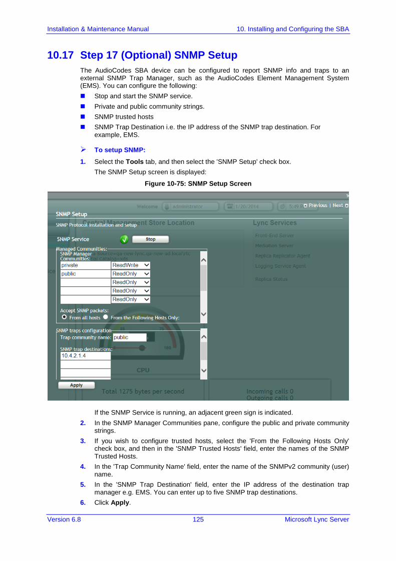
Installation & Maintenance Manual 10. Installing and Configuring the SBA
Version 6.8 125 Microsoft Lync Server
10.17 Step 17 (Optional) SNMP Setup The AudioCodes SBA device can be configured to report SNMP info and traps to an external SNMP Trap Manager, such as the AudioCodes Element Management System (EMS). You can configure the following: Stop and start the SNMP service. Private and public community strings. SNMP trusted hosts SNMP Trap Destination i.e. the IP address of the SNMP trap destination. For
example, EMS.
To setup SNMP:
1. Select the Tools tab, and then select the 'SNMP Setup' check box. The SNMP Setup screen is displayed:
Figure 10-75: SNMP Setup Screen
If the SNMP Service is running, an adjacent green sign is indicated. 2. In the SNMP Manager Communities pane, configure the public and private community
strings. 3. If you wish to configure trusted hosts, select the 'From the Following Hosts Only'
check box, and then in the 'SNMP Trusted Hosts' field, enter the names of the SNMP Trusted Hosts.
4. In the 'Trap Community Name' field, enter the name of the SNMPv2 community (user) name.
5. In the 'SNMP Trap Destination' field, enter the IP address of the destination trap manager e.g. EMS. You can enter up to five SNMP trap destinations.
6. Click Apply.

Installation & Maintenance Manual 126 Document #: LTRT-39164
Mediant 800B SBA
The following screen is displayed:
Figure 10-76: SNMP Setup-Restart Confirmation
7. Click OK, and then click Restart.
The following screen is displayed:
Figure 10-77: SNMP Setup after Restart

Installation & Maintenance Manual 10. Installing and Configuring the SBA
Version 6.8 127 Microsoft Lync Server
If the SNMP service is stopped, the following screen is displayed:
Figure 10-78: SNMP Service Started
8. Click Start to start the SNMP service.
The following screen is displayed:
Figure 10-79: SNMP Service Confirmation

Installation & Maintenance Manual 128 Document #: LTRT-39164
Mediant 800B SBA
If SNMP service is not installed, the following screen is displayed:
Figure 10-80: SNMP Service is not Installed
9. Click Install to install the SNMP service; the following screen is displayed:
Figure 10-81: SNMP Service Install Confirmation

Installation & Maintenance Manual 10. Installing and Configuring the SBA
Version 6.8 129 Microsoft Lync Server
10. Click the Tools tab, and then select the 'SNMP Setup' check box ;the following screen is displayed:
Figure 10-82: SNMP Setup

Installation & Maintenance Manual 130 Document #: LTRT-39164
Mediant 800B SBA
10.18 Step 18: Completing SBA Setup Once you have completed all configurations as described in the previous sections, you need to perform the procedure described below to complete the SBA setup.
To complete SBA setup:
1. Log in to the SBA Web wizard (if not logged in already). 2. Select the Setup tab, and then select the 'Complete Setup' checkbox; the Complete
Setup screen appears:
Figure 10-83: Complete Setup Screen
3. Click Complete; the following screen appears, indicating that the SBA setup is complete:
Figure 10-84: Complete Setup – Setup Completed

Installation & Maintenance Manual 10. Installing and Configuring the SBA
Version 6.8 131 Microsoft Lync Server
A green check mark appears next to the 'Complete Setup' option under the Setup tab, as shown in the figure below.
Figure 10-85: Complete Setup – Completed Successfully
10.19 Monitoring and Maintenance Actions This chapter describes basic SBA maintenance activities.
10.19.1 Viewing General SBA Status in the Home Page The general operating status of the SBA can be viewed in the Home page. This page displays the following: Central management store location SBA services status (stopped or running) CPU and network usages Number of incoming and outgoing calls

Installation & Maintenance Manual 132 Document #: LTRT-39164
Mediant 800B SBA
Figure 10-86: Home Page
Note: The components' statuses shown in the Home Page are also shown in the EMS GUI when the SBA is connected to the EMS. For more information, refer to the EMS User's manual.
10.19.2 Starting and Stopping SBA Services You can stop and start SBA services as described in the procedure below.
To start and stop services:
1. Select the Tools menu tab, and then select the 'Start or Stop Service' check box; the Start and Stop Service page appears:

Installation & Maintenance Manual 10. Installing and Configuring the SBA
Version 6.8 133 Microsoft Lync Server
Figure 10-87: Start and Stop Service Page
2. Stop or Start the following services: • Front-End Server • Mediation Server • Replica Replicator Agent • Logging Service Agent
3. Select one of the following actions as required: • Start All: Starts the services on the SBA • Stop All: Stops the services on the SBA • Restart Server: Restarts the server • Shutdown Server: Shuts down the server

Installation & Maintenance Manual 134 Document #: LTRT-39164
Mediant 800B SBA
10.19.3 Viewing Logged Events The procedure below describes how to view and handle logged events.
To view and handle logged events:
1. Select the Logs tab; the Logs screen appears displaying logged events:
Figure 10-88: Logs Screen Displaying Logged Events
2. To view details of a logged event, select the event.
Figure 10-89: Detailed Log Display
3. To clear the displayed log, click the Clear Logs button. To export the logged events, click the Export Logs.
10.19.4 Logging Out The procedure below describes how to log out the SBA Management Interface.
To log out the SBA Web wizard:
Click the Logout button in the top right-hand corner of the screen.

4
Part V Configuring the PSTN Gateway This part provides step-by-step procedures for configuring the PSTN Gateway functionality of the Mediant 800B SBA located at the branch office. The configuration is done through the embedded Web server (Web interface) of the Mediant 800B PSTN Gateway.


Installation & Maintenance Manual 11. Configuring the PSTN Gateway
Version 6.8 137 Microsoft Lync Server
11 Configuring the PSTN Gateway This section provides step-by-step procedures for configuring the PSTN Gateway functionality of the Mediant 800B SBA located at the branch office. The configuration is done through the embedded Web server (Web interface) of the PSTN Gateway.
Note: Before configuring the PSTN Gateway, ensure the following:
• The PSTN Gateway is running latest GA 6.80A SIP firmware Version. • The PSTN Gateway must be installed with the following Feature Keys:
√ MSFT - enables working with Microsoft Lync √ IPSEC, MediaEncryption, StrongEncryption, and EncryptControlProtocol - enable
working with TLS √ Before beginning to configure the E-SBC, select the Full option in the Web
interface to display the full Navigation tree:
√ When the E-SBC is reset, the Web interface reverts to Basic display.

Installation & Maintenance Manual 138 Document #: LTRT-39164
Mediant 800B SBA
11.1 Configuring the Mediation Server The procedure below describes how to configure the address (IP address or FQDN) of the Mediation Server through which the PSTN Gateway communicates with Lync. The PSTN Gateway forwards all telephone calls (PBX/PSTN and analog devices) to the Mediation Server using this configured address. The address is configured in the PSTN Gateway as a proxy server. In other words, the Mediation Server acts as a proxy server (without registration) for the PSTN Gateway. If you have more than one Mediation Server in the cluster, proxy redundancy functionality can also be configured. If the Mediation Server running on the Mediant 800B SBA is unavailable (i.e., a SIP 503 is received in response to an INVITE), then the PSTN Gateway re-sends the INVITE to the next Mediation Server (located at the datacenter).
To configure the Mediation Server:
1. Open the Proxy & Registration page (Configuration tab > VoIP menu > SIP Definitions > Proxy & Registration).
Figure 11-1: Proxy & Registration Page
a. From the 'Use Default Proxy' drop-down list, select Yes to enable the Mediation Server to serve as a proxy server.
b. From the 'Redundancy Mode' drop-down list, select Homing. If the SBA application fails and the PSTN Gateway switches over to the Mediation Server at the datacenter, then when the SBA application resumes functionality again, the PSTN Gateway switches back to the Mediation Service on the SBA application.
c. From the 'Redundant Routing Mode' drop-down list, select Proxy. This setting ensures that if a SIP 5xx message is received in response to an INVITE message sent to the primary proxy (i.e., Mediation Server on the Mediant 800B SBA), the PSTN Gateway re-sends it to the redundant proxy (i.e., Mediation Server at the datacenter). To configure alternative routing upon receipt of a SIP 503 response (as required by Lync), see Step 3 on page 140.
d. Click Submit.
1a
1b
1c

Installation & Maintenance Manual 11. Configuring the PSTN Gateway
Version 6.8 139 Microsoft Lync Server
2. Click the Proxy Set Table button to open the 'Proxy Sets Table' page:
Figure 11-2: Proxy Sets Table Page
a. In the 'Proxy Address' fields, configure two proxy servers for redundancy. If the SBA application fails (at the branch office), the PSTN Gateway switches over to the Mediation Server located at the datacenter.
♦ Index 1: IP address or FQDN of the Mediation Server running on the Mediant 800B SBA (configured in Section 11.3.1.4 on page 146).
♦ Index 2: IP address or FQDN of the Mediation Server running at the datacenter.
Note: If you configured the Mediation Server address as an FQDN, ensure that you configure the DNS server (see Section 11.3.1.2 on page 145).
b. In the 'Transport Type' drop-down list, select the Transport Type (TLS or TCP) for
these proxies. For more information on TLS and TCP Transport Type configuration, see Section 11.3 on page 143.
c. From the 'Enable Proxy Keep Alive' drop-down list, select Using Options to discover whether a particular Mediation Server in the cluster is available.
d. From the 'Is Proxy Hot Swap' drop-down list, select Yes. If there is no response from the first Mediation Server after a user-defined number of retransmissions, the INVITE message is sent to the redundant Mediation Server. The number of retransmissions is configured by the Number of RTX Before Hot-Swap parameter in the 'Proxy & Registration' page (see Step 1 on page 138).
e. Click Submit to apply your settings.
2a 2b
2c
2d

Installation & Maintenance Manual 140 Document #: LTRT-39164
Mediant 800B SBA
3. When the PSTN Gateway receives a SIP 503 response from the Mediation Server in response to an INVITE, it re-sends the INVITE to the redundant Mediation Server (located at the datacenter). To achieve this, you need to configure the receipt of a SIP 503 response as a reason for IP alternative routing: a. Open the 'Reasons for Alternative Routing' page (Configuration tab > VoIP
menu > GW and IP to IP > Routing > Alternative Routing Reasons).
Figure 11-3: Reasons for Alternative Routing Page
b. Under the Tel to IP Reasons group, from the 'Reason 1' drop-down list, select 503.
c. Click Submit. d. Open the 'SIP General Parameters' page (Configuration tab > VoIP menu > SIP
Definitions > General Parameters).
3b
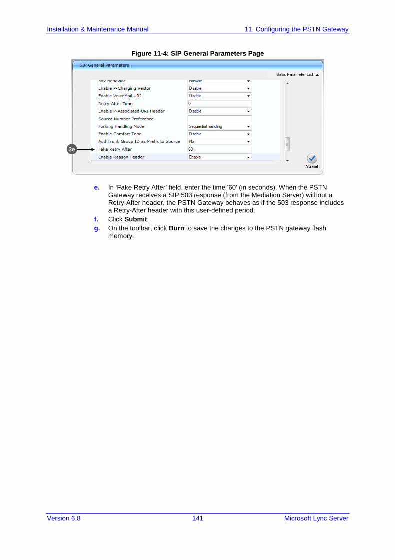
Installation & Maintenance Manual 11. Configuring the PSTN Gateway
Version 6.8 141 Microsoft Lync Server
Figure 11-4: SIP General Parameters Page
e. In ‘Fake Retry After’ field, enter the time '60' (in seconds). When the PSTN Gateway receives a SIP 503 response (from the Mediation Server) without a Retry-After header, the PSTN Gateway behaves as if the 503 response includes a Retry-After header with this user-defined period.
f. Click Submit. g. On the toolbar, click Burn to save the changes to the PSTN gateway flash
memory.
3e

Installation & Maintenance Manual 142 Document #: LTRT-39164
Mediant 800B SBA
11.2 Restricting Communication to Mediation Server Only The procedure below describes how to restrict IP communication, by allowing communication only between the PSTN Gateway and the Mediation Server. This ensures that the PSTN Gateway accepts and sends SIP calls only from and to the Mediation Server (as required by Microsoft). This is done by enabling the IP Security feature and then defining the allowed (“administrative” list) IP addresses (or FQDNs) in the Proxy Set table.
To allow IP communication only between the PSTN Gateway and Mediation Server:
1. Open the Advanced Parameters page (Configuration tab > VoIP menu > SIP Definitions > Advanced Parameters).
Figure 11-5: Advanced Parameters Page
2. From the ‘IP Security’ drop-down list, select Secure Incoming calls to enable the security feature to accept and send SIP calls only from and to user-defined IP addresses or FQDN (i.e., Mediation server) configured in the ‘Proxy Set table’ (see Step 1).
3. Click Submit to apply your settings. 4. On the toolbar, click Burn to save the changes to the Enhanced gateway flash
memory.
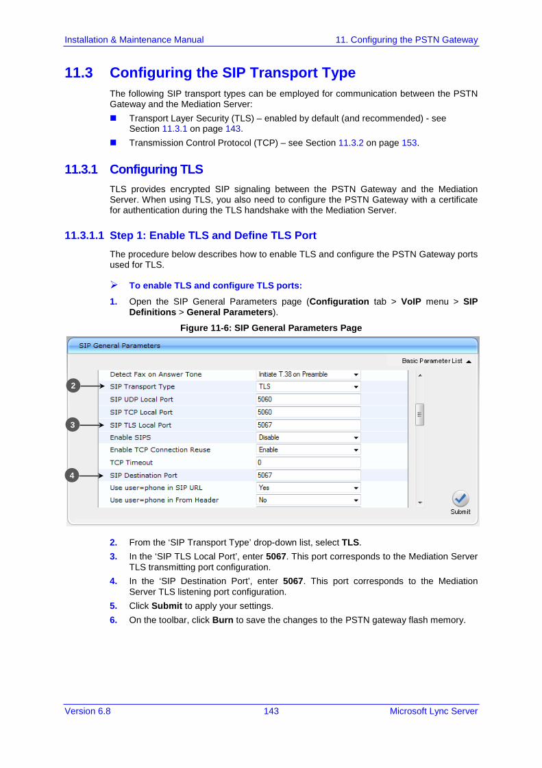
Installation & Maintenance Manual 11. Configuring the PSTN Gateway
Version 6.8 143 Microsoft Lync Server
11.3 Configuring the SIP Transport Type The following SIP transport types can be employed for communication between the PSTN Gateway and the Mediation Server: Transport Layer Security (TLS) – enabled by default (and recommended) - see
Section 11.3.1 on page 143. Transmission Control Protocol (TCP) – see Section 11.3.2 on page 153.
11.3.1 Configuring TLS TLS provides encrypted SIP signaling between the PSTN Gateway and the Mediation Server. When using TLS, you also need to configure the PSTN Gateway with a certificate for authentication during the TLS handshake with the Mediation Server.
11.3.1.1 Step 1: Enable TLS and Define TLS Port The procedure below describes how to enable TLS and configure the PSTN Gateway ports used for TLS.
To enable TLS and configure TLS ports:
1. Open the SIP General Parameters page (Configuration tab > VoIP menu > SIP Definitions > General Parameters).
Figure 11-6: SIP General Parameters Page
2. From the ‘SIP Transport Type’ drop-down list, select TLS. 3. In the ‘SIP TLS Local Port’, enter 5067. This port corresponds to the Mediation Server
TLS transmitting port configuration. 4. In the ‘SIP Destination Port’, enter 5067. This port corresponds to the Mediation
Server TLS listening port configuration. 5. Click Submit to apply your settings. 6. On the toolbar, click Burn to save the changes to the PSTN gateway flash memory.
2
3
4

Installation & Maintenance Manual 144 Document #: LTRT-39164
Mediant 800B SBA
11.3.1.2 Step 2: Configure the NTP Server The procedure below describes how to configure the Network Time Protocol (NTP) server. This is important for maintaining the correct time and date on the PSTN Gateway, by synchronizing it with a third-party NTP server. This ensures that the PSTN Gateway has the same date and time as the Certification Authority (CA), discussed later in Section 11.3.1 on page 143.
To configure the NTP server:
1. Open the Application Settings page (Configuration tab > System menu > Application Settings).
Figure 11-7: Application Settings Page
2. In the 'NTP Server Address (IP or FQDN) ' field, enter the IP address of the NTP
server. 3. Click Submit to apply your changes. 4. On the toolbar, click Burn to save the changes to the PSTN gateway flash memory.
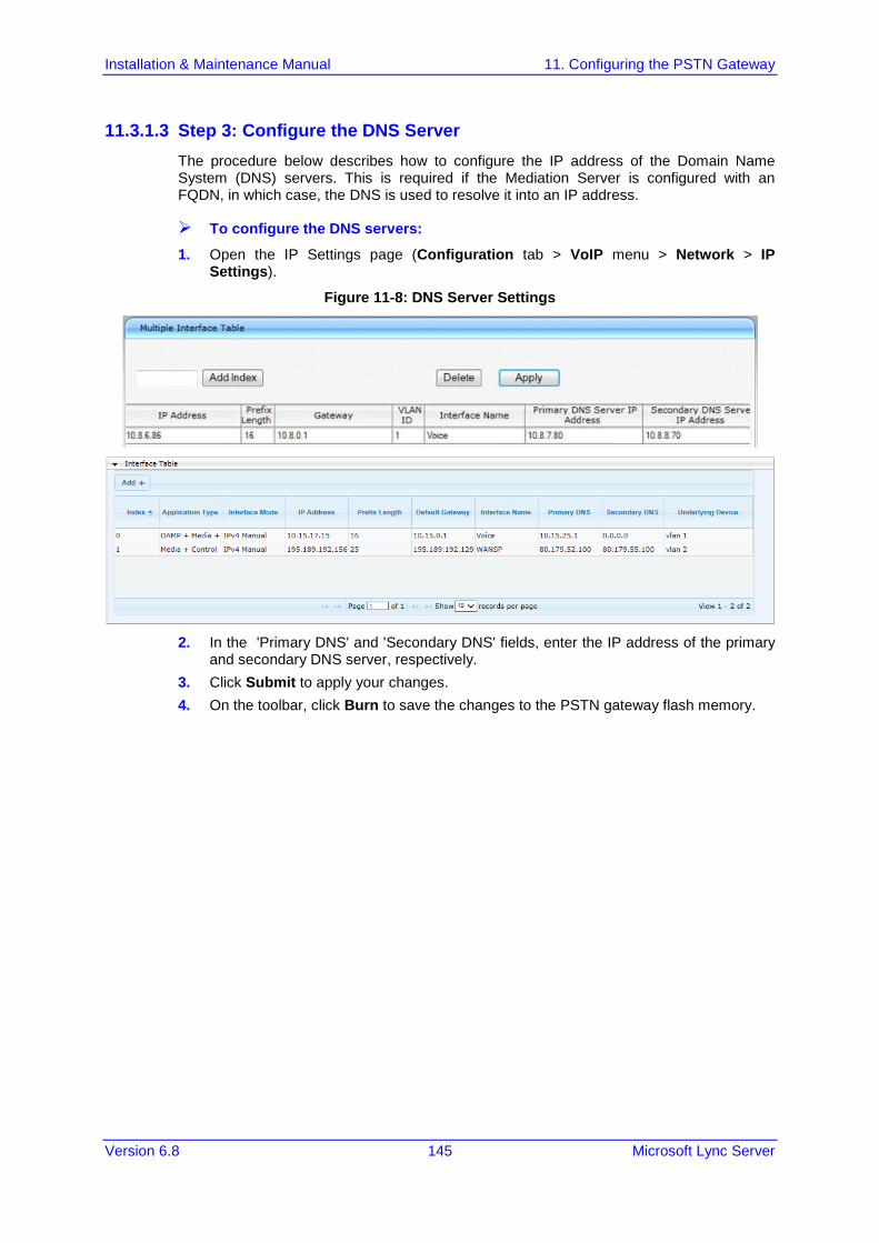
Installation & Maintenance Manual 11. Configuring the PSTN Gateway
Version 6.8 145 Microsoft Lync Server
11.3.1.3 Step 3: Configure the DNS Server The procedure below describes how to configure the IP address of the Domain Name System (DNS) servers. This is required if the Mediation Server is configured with an FQDN, in which case, the DNS is used to resolve it into an IP address.
To configure the DNS servers:
1. Open the IP Settings page (Configuration tab > VoIP menu > Network > IP Settings).
Figure 11-8: DNS Server Settings
2. In the 'Primary DNS' and 'Secondary DNS' fields, enter the IP address of the primary
and secondary DNS server, respectively. 3. Click Submit to apply your changes. 4. On the toolbar, click Burn to save the changes to the PSTN gateway flash memory.

Installation & Maintenance Manual 146 Document #: LTRT-39164
Mediant 800B SBA
11.3.1.4 Step 4: Configure the Gateway Name The procedure below describes how to configure the host name for the PSTN Gateway. This appears as the URI host name in the SIP From header in INVITE messages sent by the PSTN Gateway to the Mediation Server. This allows the Mediation Server to identify the PSTN Gateway (if required), when using certificates for TLS (see below).
To configure the SIP gateway name:
1. Open the Proxy & Registration page (Configuration tab > VoIP menu > SIP Definitions > Proxy & Registration).
Figure 11-9: Proxy & Registration Page
2. In the 'Gateway Name' field, assign a unique FQDN name to the PSTN Gateway
within the domain, for example,'gw.lync2013.com'.This name is identical to the name that is configured in the Lync Topology Builder (see Section 8.1 on page 56).
3. Click Submit to apply your settings. 4. On the toolbar, click Burn to save the changes to the PSTN gateway flash memory.

Installation & Maintenance Manual 11. Configuring the PSTN Gateway
Version 6.8 147 Microsoft Lync Server
11.3.1.5 Step 5: Configure a Certificate This step describes how to exchange a certificate with Microsoft Certificate Authority (CA). The certificate is used by the E-SBC to authenticate the connection with Lync Server 2013. The procedure involves the following main steps: a. Configuring TLS b. Generating a Certificate Signing Request (CSR). c. Requesting Device Certificate from CA. d. Obtaining Trusted Root Certificate from CA.
To configure the TLS version 1.0:
1. Open the TLS Contexts page (Configuration tab > VoIP menu > Security > General Security Settings). In the ‘TLS Version’ field, choose the ‘TLS 1.0 only’ from the drop-down list. Use TLS version 1.0 only. AudioCodes recommends implementing only TLS to avoid flaws in SSL
Figure 11-10: Configuring TLS version 1.0
2. Click Submit. 3. Open the TLS Contexts page (Configuration tab > System menu > TLS Contexts). 4. In the TLS Contexts table, select the required TLS Context index row, and then click
the Context Certificates button, located at the bottom of the TLS Contexts page; the Context Certificates page appears.
5. Under the Certificate Signing Request group, do the following: h. In the 'Subject Name [CN]' field, enter the E-SBC FQDN name
(e.g., ITSP-GW.ilync15.local). i. Fill in the rest of the request fields according to your security provider's
instructions. 6. Click the Create CSR button; a textual certificate signing request is displayed in the
area below the button:

Installation & Maintenance Manual 148 Document #: LTRT-39164
Mediant 800B SBA
Figure 11-11: Certificate Signing Request – Creating CSR
Note: The value entered in this field must be identical to the gateway name configured in the Topology Builder for Lync Server 2013 (see Chapter 8 on page 55).
7. Copy the CSR from the line "----BEGIN CERTIFICATE" to "END CERTIFICATE
REQUEST----" to a text file (such as Notepad), and then save it to a folder on your computer with the file name, certreq.txt.
8. Open a Web browser and navigate to the Microsoft Certificates Services Web site at http://<certificate server>/CertSrv.
Figure 11-12: Microsoft Certificate Services Web Page
9. Click Request a certificate.

Installation & Maintenance Manual 11. Configuring the PSTN Gateway
Version 6.8 149 Microsoft Lync Server
Figure 11-13: Request a Certificate Page
10. Click advanced certificate request, and then click Next. Figure 11-14: Advanced Certificate Request Page
11. Click Submit a certificate request ..., and then click Next.

Installation & Maintenance Manual 150 Document #: LTRT-39164
Mediant 800B SBA
Figure 11-15: Submit a Certificate Request or Renewal Request Page
12. Open the certreq.txt file that you created and saved above, and then copy its contents to the 'Saved Request' field.
13. From the 'Certificate Template' drop-down list, select Web Server. 14. Click Submit.
Figure 11-16: Certificate Issued Page
15. Select the Base 64 encoded option for encoding, and then click Download certificate.
16. Save the file as gateway.cer to a folder on your computer. 17. Click the Home button or navigate to the certificate server at http://<Certificate
Server>/CertSrv. 18. Click Download a CA certificate, certificate chain, or CRL.

Installation & Maintenance Manual 11. Configuring the PSTN Gateway
Version 6.8 151 Microsoft Lync Server
Figure 11-17: Download a CA Certificate, Certificate Chain, or CRL Page
19. Under the 'Encoding method' group, select the Base 64 option for encoding. 20. Click Download CA certificate. 21. Save the file as certroot.cer to a folder on your computer. 22. In the E-SBC's Web interface, return to the TLS Contexts page and do the following:
a. Scroll down to the Upload certificates files from your computer group, click the Browse button corresponding to the 'Send Device Certificate...' field, navigate to the gateway.cer certificate file that you saved on your computer above , and then click Send File to upload the certificate to the E-SBC.
Figure 11-18: Upload Device Certificate Files from your Computer Group
b. In the E-SBC's Web interface, return to the TLS Contexts page. c. In the TLS Contexts table, select the required TLS Context index row, and then
click the TLS Context Trusted-Roots Certificates button, located at the bottom of the TLS Contexts page; the Trusted Certificates page appears.
d. Click the Import button, and then select the certificate file to load.
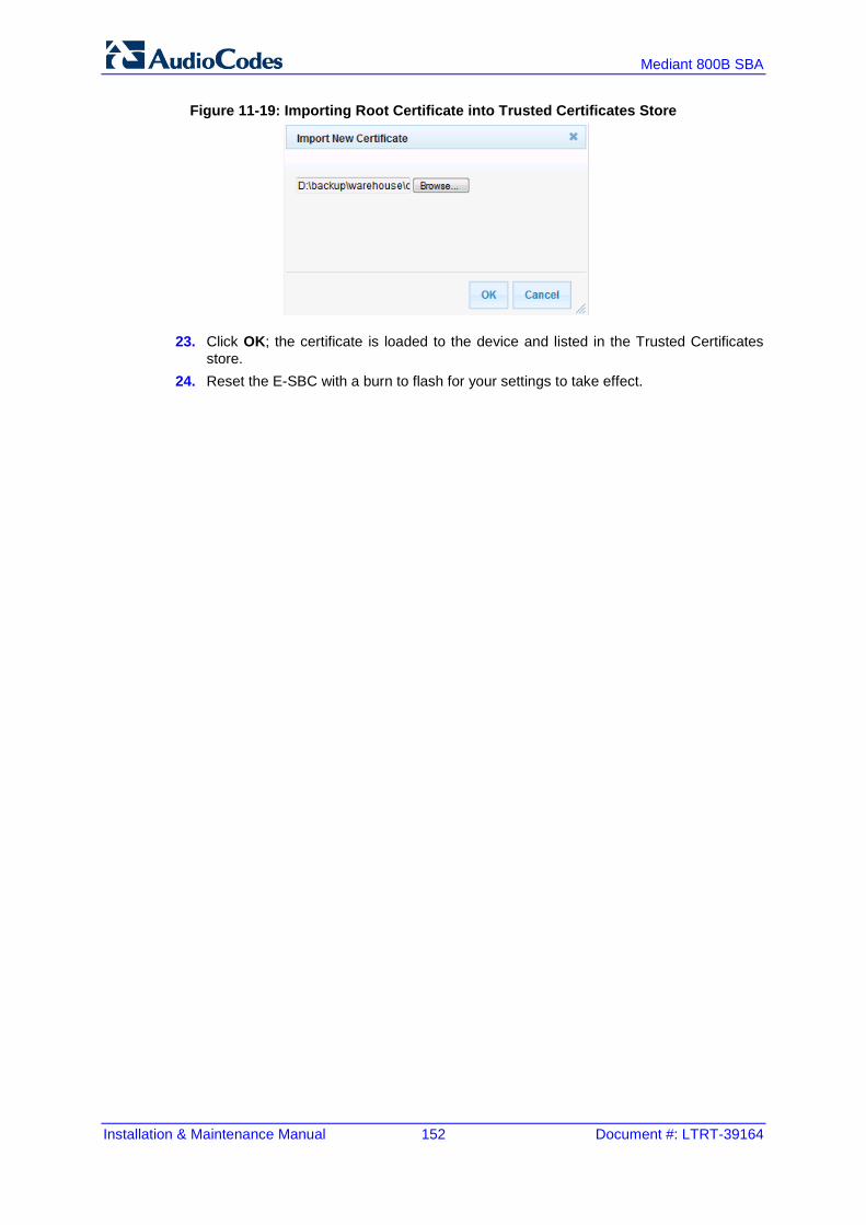
Installation & Maintenance Manual 152 Document #: LTRT-39164
Mediant 800B SBA
Figure 11-19: Importing Root Certificate into Trusted Certificates Store
23. Click OK; the certificate is loaded to the device and listed in the Trusted Certificates store.
24. Reset the E-SBC with a burn to flash for your settings to take effect.

Installation & Maintenance Manual 11. Configuring the PSTN Gateway
Version 6.8 153 Microsoft Lync Server
11.3.2 Configuring TCP Transport Type TCP provides unencrypted SIP signaling between the PSTN Gateway and Mediation Server. The procedure below describes how to configure the SIP TCP transport type.
Note: Microsoft does not recommend implementing TCP for the SIP transport type between the PSTN Gateway and the Mediation Server.
To set SIP transport type to TCP:
1. Open the SIP General Parameters page (Configuration tab > VoIP menu > SIP Definitions > General Parameters).
Figure 11-20: SIP General Parameters Page
2. From the 'SIP Transport Type' drop-down list, select TCP. 3. In the 'SIP TCP Local Port' field, enter the same Gateway listening TCP port number
as was configured on the Topology Builder for the gateway. 4. Click Submit to apply your changes. 5. On the toolbar, click Burn to save the changes to the PSTN gateway flash memory.
2
3

Installation & Maintenance Manual 154 Document #: LTRT-39164
Mediant 800B SBA
11.4 Configuring Secure Real-Time Transport Protocol If you configure TLS as the SIP transport type between the PSTN Gateway and Mediation Server, you must enable Secure RTP (SRTP) encryption and set its mode of operation to one of the following (and that which matches the SRTP supported at the Mediation Server): Preferable (default): The PSTN Gateway initiates encrypted calls. However, if
negotiation of the cipher suite fails, an unencrypted call is established. Incoming calls that don't include encryption information are accepted. This option is not supported by the Mediation server.
Mandatory: The PSTN Gateway initiates encrypted calls, but if negotiation of the cipher suite fails, the call is terminated. Incoming calls that don't include encryption information are rejected.
Preferable - Single Media: The PSTN Gateway sends SDP with a single media ('m=') line only (e.g., m=audio 6000 RTP/AVP 8 0 101) with RTP/AVP and crypto keys. The remote SIP user agent (UA) can respond with SRTP or RTP parameters: • If the Mediation Server does not support SRTP, it uses RTP and ignores the
crypto lines. • If the PSTN Gateway receives an SDP offer with a single media, it responds with
SRTP (RTP/SAVP) if the Media Security parameter is set to ‘Enable’. If SRTP is not supported (i.e., ‘Media Security’ is set to ‘Disabled’), it responds with RTP.
To configure SRTP:
1. Open the Media Security page (Configuration tab > VoIP menu > Media > Media Security).
Figure 11-21: Media Security Page
2. From the 'Media Security' drop-down list, select Enable to enable SRTP. 3. From the 'Media Security Behavior' drop-down list, select one of the following:
• Mandatory: To force Media Security, usually used when the Mediation Server is configured to Encryption "Required".
• Preferable-Single media: To prefer Media Security but support RTP as well, usually used when the Mediation Server is configured to Encryption "Optional".
2 3
4
5

Installation & Maintenance Manual 11. Configuring the PSTN Gateway
Version 6.8 155 Microsoft Lync Server
4. In the 'Master Key Identifier (MKI) Size' field, enter 1. This configures the size (in bytes) of the MKI in SRTP Tx packets.
5. From the 'Enable Symmetric MKI Negotiation' drop-down list, select Enable. 6. Click Submit to apply your changes. 7. On the toolbar, click Burn to save the changes to the PSTN gateway flash memory. 8. On the toolbar, from the Device Actions drop-down list, choose Reset, and then in the‘
Maintenance Actions’ page, click the Reset button; the Mediant 800B resets and your settings are saved to the flash memory.
11.5 Configuring Voice Coders (with Silence Suppression) The PSTN Gateway communicates with the Mediation Server using either the G.711 A-law or G.711 µ-law (Mu-Law) voice coder. In addition, silence suppression can be enabled per coder, which is recommended for improving the performance of the Mediation Server. The procedure below shows how you can change the default coder.
To configure the voice coder and silence suppression:
1. Open the Coders page (Configuration tab > VoIP menu > Coders and Profiles > Coders).
Figure 11-22: Coders Table Page
2. From the 'Coder Name' drop-down list, select the required coder. 3. From the 'Silence Suppression' drop-down list, select Enable. 4. Click Submit. 5. On the toolbar, click Burn to save the changes to the PSTN gateway flash memory.

Installation & Maintenance Manual 156 Document #: LTRT-39164
Mediant 800B SBA
11.6 Configuring Comfort Noise and Gain Control The Lync network provides high voice quality by implementing suppression of typing noise during calls and improved generation of “comfort noise,” which reduces hissing and smoothens over the discontinuous flow of audio packets. You may need to configure the PSTN Gateway to match these voice quality features, by enabling silence suppression, comfort noise generation, automatic gain control (AGC), and echo canceller (enabled by default).
Note: Silence suppression is configured per coder type, as described in Section 11.5 on page 155.
To configure voice quality:
1. Open the RTP/RTCP Settings page (Configuration tab > VoIP menu > Media > RTP/RTCP Settings).
Figure 11-23: RTP/RTCP Settings Page
2. From the ‘Enable RFC 3389 CN payload Type’ drop-down list, verify Enable 3. From the ‘Comfort Noise Generation Negotiation’ drop-down list, select Enable. 4. Click Submit. 5. On the toolbar, click Burn to save the changes to the PSTN gateway flash memory. 6. Open the 'IPMedia Settings' page (Configuration tab > VoIP menu > Media >
IPMedia Settings).
2
3

Installation & Maintenance Manual 11. Configuring the PSTN Gateway
Version 6.8 157 Microsoft Lync Server
Figure 11-24: IPMedia Settings Page
7. From the ‘IPMedia Detectors’ drop-down list, select Enable. This parameter requires a PSTN Gateway reset (see Step 8 below).
8. From the ‘Enable AGC’ drop-down list, select Enable. 9. Click Submit to apply your changes. 10. On the toolbar, click Burn to save the changes to the PSTN gateway flash memory. 11. On the toolbar, from the Device Actions drop-down list, choose Reset, and then in the‘
Maintenance Actions’ page, click the Reset button; the Mediant 800B resets and your settings are saved to the flash memory.
7
8

Installation & Maintenance Manual 158 Document #: LTRT-39164
Mediant 800B SBA
11.7 Configuring Early Media Early media refers to audio and video that is exchanged before a call is accepted by the recipient. Early media generated by the caller includes voice commands or dual-tone multi frequency (DTMF) tones to activate interactive voice response (IVR) systems. Early media generated by the call recipient include ringback tones, announcements, and requests for input. Enhanced early media support in Lync enables a caller to hear a ringback tone generated by the call recipient’s mobile phone. This is also the case in team-call scenarios, where a call is routed to two team members, one of whom has configured simultaneous ringing for his or her mobile phone. According to Lync requirements, AudioCodes PSTN Gateway must send a SIP 183 with SDP immediately after it receives an INVITE. The RTP packets however, will not be sent until the PSTN Gateway receives an ISDN Progress, Alerting and Progress Indicator or Connect message. For example, if the PSTN Gateway receives ISDN Progress, it starts sending RTP packets according to initial negotiation, but there is no need to re-send the 183 response. You may need to configure the PSTN Gateway's early media feature to support Lync 2013 enhanced early media feature.
To configure the Early Media feature:
1. Open the SIP General Parameters page (Configuration tab > VoIP > SIP Definitions > SIP General Parameters).
Figure 11-25: SIP General Parameters Page (1)
2. From the ‘Enable Early Media’ drop-down list, select Enable. 3. From the ‘Play Ringback Tone to Tel’ drop-down list, select Play Local Until Remote
Media Arrive. If a SIP 180 response is received and the voice channel is already open (due to a previous 183 early media response or due to an SDP in the current 180 response), the PSTN Gateway plays a local ringback tone if there are no prior received RTP packets. The PSTN Gateway stops playing the local ringback tone as soon as it starts receiving RTP packets. At this stage, if the PSTN Gateway receives additional 18x responses, it does not resume playing the local ringback tone.

Installation & Maintenance Manual 11. Configuring the PSTN Gateway
Version 6.8 159 Microsoft Lync Server
4. From the ‘Forking Handling Mode’ drop-down list, select Sequential handling. The PSTN Gateway opens a voice stream toward the first 18x SIP response that includes an SDP and disregards any 18x response with an SDP received thereafter.
Figure 11-26: SIP General Parameters Page (2)
5. Click Submit to apply your changes. 6. Open the Advanced Parameters page (Configuration tab > VoIP menu > SIP
Definitions > Advanced Parameters).

Installation & Maintenance Manual 160 Document #: LTRT-39164
Mediant 800B SBA
Figure 11-27: Advanced Parameters Page
7. From the ‘Enable Early 183’ drop-down list, select Enable. 8. Click Submit to apply your changes. 9. On the toolbar, click Burn to save the changes to the PSTN gateway flash memory.
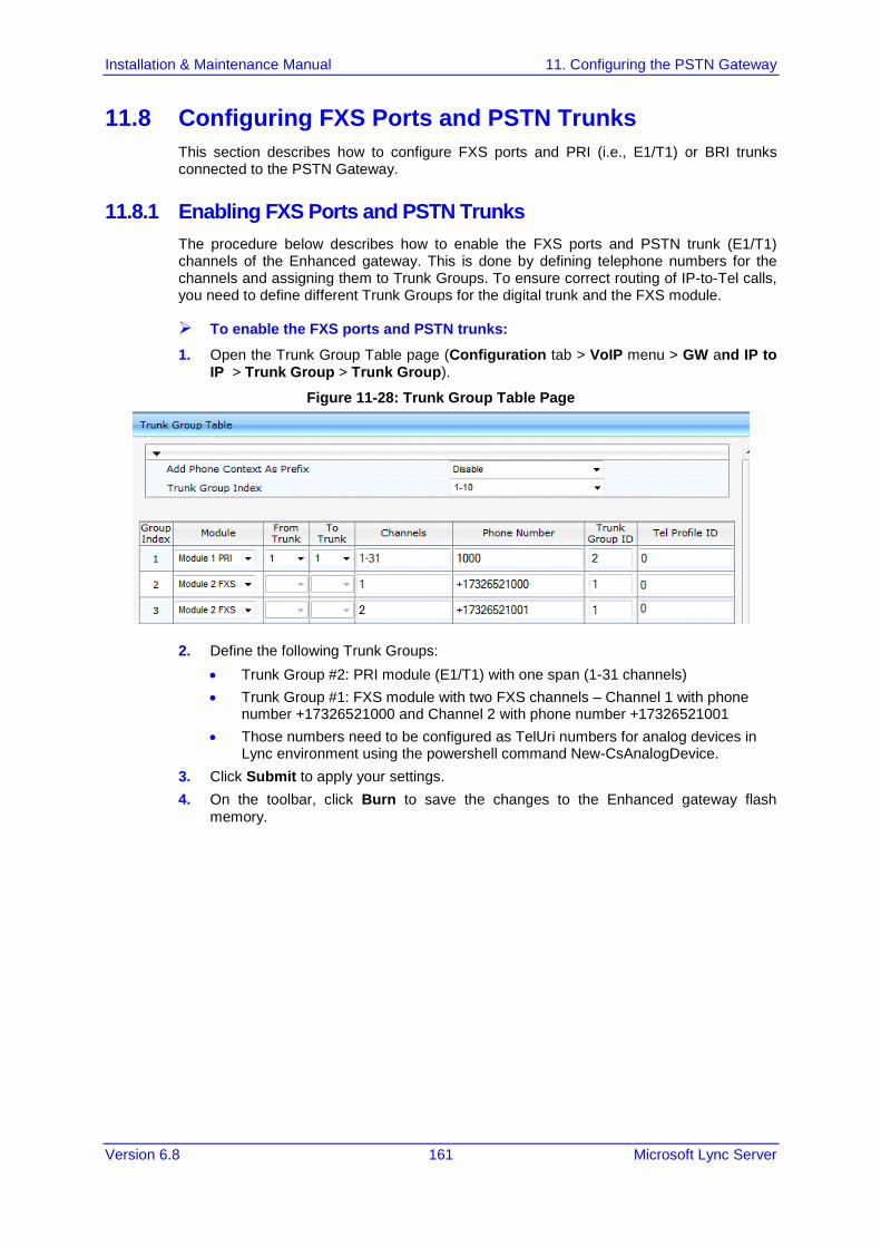
Installation & Maintenance Manual 11. Configuring the PSTN Gateway
Version 6.8 161 Microsoft Lync Server
11.8 Configuring FXS Ports and PSTN Trunks This section describes how to configure FXS ports and PRI (i.e., E1/T1) or BRI trunks connected to the PSTN Gateway.
11.8.1 Enabling FXS Ports and PSTN Trunks The procedure below describes how to enable the FXS ports and PSTN trunk (E1/T1) channels of the Enhanced gateway. This is done by defining telephone numbers for the channels and assigning them to Trunk Groups. To ensure correct routing of IP-to-Tel calls, you need to define different Trunk Groups for the digital trunk and the FXS module.
To enable the FXS ports and PSTN trunks:
1. Open the Trunk Group Table page (Configuration tab > VoIP menu > GW and IP to IP > Trunk Group > Trunk Group).
Figure 11-28: Trunk Group Table Page
2. Define the following Trunk Groups: • Trunk Group #2: PRI module (E1/T1) with one span (1-31 channels) • Trunk Group #1: FXS module with two FXS channels – Channel 1 with phone
number +17326521000 and Channel 2 with phone number +17326521001 • Those numbers need to be configured as TelUri numbers for analog devices in
Lync environment using the powershell command New-CsAnalogDevice. 3. Click Submit to apply your settings. 4. On the toolbar, click Burn to save the changes to the Enhanced gateway flash
memory.

Installation & Maintenance Manual 162 Document #: LTRT-39164
Mediant 800B SBA
11.8.1.1 Configuring the Channel Select Method Once you have enabled the PSTN trunk and FXS ports, and assigned them to Trunk Groups, you need to configure the method for which IP-to-Tel calls are assigned to channels within each Trunk Group.
To configure the channel select method for each Trunk Group:
1. Open the Trunk Group Settings page (Configuration tab > VoIP menu > GW and IP to IP > Trunk Group > Trunk Group Settings).
Figure 11-29: Trunk Group Setting Page
2. For the FXS ports (i.e., Trunk Group #1), from the ‘Channel Select Mode’ drop-down list, select By Dest Phone Number. This setting sends the call to a specific FXS user according to the called (destination) number.
3. For the PSTN trunk (i.e., Trunk Group #2), from the ‘Channel Select Mode’ drop-down select Cyclic Ascending. This setting sends the call to the next available channel, in ascending cyclic order.
4. Click Submit to apply your settings. 5. On the toolbar, click Burn to save the changes to the Enhanced gateway flash
memory.
2
3

Installation & Maintenance Manual 11. Configuring the PSTN Gateway
Version 6.8 163 Microsoft Lync Server
11.8.2 Configuring IP-to-Trunk Group Routing The procedure below describes how to configure an IP-to-Trunk Group routing rule, whereby all calls to +17326521000 and +17326521001 from the Mediation Server need to be route to Trunk Group 1 (the internal FXS ports) all other calls from Mediation server need to be route to Trunk Group 2 (the PRI trunk)
To configure an IP-to-Trunk Group routing rule:
1. Open the Inbound IP Routing Table page (Configuration tab > VoIP menu > GW and IP to IP > Routing > IP to Trunk Group Routing).
Figure 11-30: Inbound IP Routing Table Page
2. In the first table entry row, enter the +1732652100[0-1] in the ‘Dest. Phone Prefix’. 3. In the ‘Trunk Group ID’ field, enter the Trunk Group to where the calls must be routed
(Trunk Group ID 1). 4. In the second table entry row, enter asterisk sign (*) in the ‘Dest. Phone Prefix’. 5. In the ‘Trunk Group ID’ field, enter the Trunk Group to where the calls must be routed
(Trunk Group ID 2). 6. Click Submit to apply your changes. 7. On the toolbar, click Burn to save the changes to the PSTN gateway flash memory.

Installation & Maintenance Manual 164 Document #: LTRT-39164
Mediant 800B SBA
11.8.3 Configuring the Trunk The procedure below describes basic configuration of the physical trunk.
To configure the physical trunk:
1. Open the Trunk Settings page (Configuration tab > VoIP menu > PSTN > Trunk Settings).
Figure 11-31: Trunk Settings Page
2. On the top of the page, a bar with trunk number icons displays the status of each trunk: • Grey - disabled • Green - active • Yellow - RAI alarm • Red - LOS / LOF alarm • Blue - AIS alarm • Orange - D-channel alarm (ISDN only) Select the Trunk that you want to configure, by clicking the desired trunk number icon.
3. If the trunk is new, configure the trunk as required. If the trunk was previously configured, click the Stop Trunk button to de-activate the trunk.
4a
4b
4c
4d
4e

Installation & Maintenance Manual 11. Configuring the PSTN Gateway
Version 6.8 165 Microsoft Lync Server
4. Basic trunk configuration: a. From the ‘Protocol Type’ drop-down list, select the required trunk protocol.
Notes:
• If the ‘Protocol Type’ field displays 'NONE' (i.e., no protocol type selected) and no other trunks have been configured, after selecting a PRI protocol type, you must reset the PSTN Gateway.
• All PRI trunks of the PSTN Gateway must be of the same line type - E1 or T1. However, different variants of the same line type can be configured on different trunks, for example, E1 Euro ISDN and E1 CAS (subject to the constraints in the Release Notes).
• BRI trunks can operate with E1 or T1 trunks. • If the trunk can’t be stopped because it provides the clock (assuming the PSTN
Gateway is synchronized with the E1/T1 clock), assign a different E1/T1 trunk to provide the clock or enable ‘TDM Bus PSTN Auto Clock’ in the 'TDM Bus Settings' page (see Section 11.8.4 on page 166).
• To delete a previously configured trunk, set the Protocol Type parameter to 'None'.
b. From the ‘Clock Master’ drop-down list, select the trunk's clock source:
♦ Recovered: Clock source is recovered from the trunk ♦ Generated: Clock source is provided by the internal TDM bus clock
source (according to the TDM Bus Clock Source parameter – see Section 11.8.4 on page 166)
c. From the ‘Line Code’ drop-down list, select the line code: ♦ B8ZS: (bipolar 8-zero substitution) for T1 trunks only ♦ HDB3: (high-density bipolar 3) for E1 trunks only ♦ AMI: (for E1 and T1)
d. From the ‘Framing Method’ drop-down list, select the required framing method. For E1 trunks always select Extended Super Frame.
e. To configure whether the trunk connected to the PBX is User or Network side for QSIG, from the 'ISDN Termination' drop-down list, select User side or Network side.
5. Continue configuring the trunk according to your requirements.
6. When you have completed configuration, click the Apply Trunk Settings button to apply the changes to the selected trunk.
7. On the toolbar, click Burn to save the changes to the PSTN gateway flash memory.

Installation & Maintenance Manual 166 Document #: LTRT-39164
Mediant 800B SBA
11.8.4 Configuring the TDM Bus The procedure below describes how to configure the TDM bus of the PSTN Gateway.
To configure the TDM bus:
1. Open the TDM Bus Settings page (Configuration tab > VoIP menu > TDM > TDM Bus Settings).
Figure 11-32: TDM Bus Settings Page
2. Configure the TDM bus parameters according to your deployment requirements. Below is a description of some of the main TDM parameters: • PCM Law Select: defines the type of PCM companding law in the input/output
TDM bus. Typically, A-Law is used for E1 and Mu-Law for T1/J1. • TDM Bus Clock Source: defines the clock source to which the PSTN Gateway
synchronizes - generate clock from local source (Internal) or recover clock from PSTN line (Network).
• TDM Bus Local Reference: defines the physical trunk ID from which the PSTN Gateway recovers (receives) its clock synchronization when the TDM Bus Clock Source is configured to recover the clock from the PSTN line.
3. Click Submit to apply your changes. 4. On the toolbar, click Burn to save the changes to the PSTN gateway flash memory. 5. On the toolbar, from the Device Actions drop-down list, choose Reset, and then in the‘
Maintenance Actions’ page, click the Reset button; the Mediant 800B resets and your settings are saved to the flash memory.
2
2
2

Installation & Maintenance Manual 11. Configuring the PSTN Gateway
Version 6.8 167 Microsoft Lync Server
11.9 Configuring Normalization Rules for E.164 Format for PBX/PSTN Connectivity Lync 2013 implements the standard E.164 format, while the PBX or PSTN implements other number formats for dialing. If the PSTN Gateway is connected to a PBX or directly to the PSTN, the PSTN Gateway may need to perform number manipulations for the called and/or calling number to match the PBX or PSTN dialing rules or to match Lync 2013 E.164 format. Therefore, the PSTN Gateway must be configured with manipulation rules to translate (i.e., normalize) numbers dialed in standard E.164 format to various formats, and vice versa. Manipulation needs to be done for outbound calls (i.e., calls received from Lync clients through Lync 2013) and inbound calls (i.e., calls destined to Lync clients). Number manipulation (and mapping of NPI/TON to SIP messages) rules are configured in the following Manipulation tables: For Tel-to-IP calls:
• Destination Phone Number Manipulation Table for Tel-to-IP Calls • Source Phone Number Manipulation Table for Tel-to-IP Calls
For IP-to-Tel calls: • Destination Phone Number Manipulation Table for IP-to-Tel Calls • Source Phone Number Manipulation Table for IP-to-Tel Calls
Number manipulation configuration examples are provided for inbound and outbound calls in Section 11.9.1 on page 171.
To configure number manipulation rules:
1. Open the required number Manipulation table (Configuration tab > VoIP menu > GW and IP to IP > Manipulations ); the relevant Manipulation table page is displayed
2. Click the Add button; the following dialog box appears:
Figure 11-33: Number Manipulation Table - Add Dialog Box
3. Click the Rule tab, and then configure the matching characteristics. For a description of the parameters, see the table below.

Installation & Maintenance Manual 168 Document #: LTRT-39164
Mediant 800B SBA
4. Click the Action tab, and then configure the manipulation operation. For a description of the parameters, see the table below.
5. Configure manipulation rules as required. 6. Click Submit to apply your changes. 7. On the toolbar, click Burn to save the settings to the PSTN Gateway; the PSTN
Gateway resets, saving the settings to flash memory.
Table 11-1: Number Manipulation Parameters Description
Parameter Description
Matching Characteristics (Rule)
Destination Prefix
Defines the destination (called) telephone number prefix and/or suffix. You can use special notations for denoting the prefix. For example, [100-199](100,101,105) denotes a number that starts with 100 to 199 and ends with 100, 101 or 105. You can also use the $ sign to denote calls without a called number.
Source Prefix
Defines the source (calling) telephone number prefix and/or suffix. You can use special notations for denoting the prefix. For example, [100-199](100,101,105) denotes a number that starts with 100 to 199 and ends with 100, 101 or 105. You can also use the $ sign to denote calls without a calling number.
Source IP Address
Defines the source IP address of the caller. This is obtained from the Contact header in the INVITE message. Notes: This parameter is applicable only to the number manipulation tables
for IP-to-Tel calls. The source IP address can include the 'x' wildcard to represent
single digits. For example: 10.8.8.xx represents all IP addresses between 10.8.8.10 to 10.8.8.99.
The source IP address can include the asterisk (*) wildcard to represent any number between 0 and 255. For example, 10.8.8.* represents all IP addresses between 10.8.8.0 and 10.8.8.255.
Source Host Prefix
Defines the URI host name prefix of the incoming SIP INVITE message in the From header. Notes: This parameter is applicable only to the number manipulation tables
for IP-to-Tel calls. The asterisk (*) wildcard can be used to denote any prefix. If the P-Asserted-Identity header is present in the incoming INVITE
message, then the value of this parameter is compared to the P-Asserted-Identity URI host name (instead of the From header).
Destination Host Prefix
Defines the Request-URI host name prefix of the incoming SIP INVITE message. Notes: This parameter is applicable only to the number manipulation tables
for IP-to-Tel calls. The asterisk (*) wildcard can be used to denote any prefix.

Installation & Maintenance Manual 11. Configuring the PSTN Gateway
Version 6.8 169 Microsoft Lync Server
Parameter Description
Source Trunk Group
Defines the source Trunk Group ID for Tel-to-IP calls. To denote all Trunk Groups, leave this field empty. Notes: The value -1 indicates that this field is ignored in the rule. This parameter is applicable only to the number manipulation tables
for Tel-to-IP calls. For IP-to-IP call routing, this parameter is not required (i.e., leave
the field empty).
Source IP Group
Defines the IP Group from where the IP call originated. Typically, the IP Group of an incoming INVITE is determined or classified using the Inbound IP Routing Table. If not used (i.e., any IP Group), leave the field empty. Notes: The value -1 indicates that this field is ignored. This parameter is applicable only to the number manipulation tables
for Tel-to-IP calls. If this Source IP Group has a Serving IP Group, then all calls from
this Source IP Group are sent to the Serving IP Group. In this scenario, this table is used only if the PreferRouteTable parameter is set to 1.
Destination IP Group
Defines the IP Group to where the call is sent. Notes: The value -1 indicates that this field is ignored. This parameter is applicable only to the Destination Phone Number
Manipulation Table for Tel -> IP Calls.
Operation (Action)
Stripped Digits From Left
Defines the number of digits to remove from the left of the telephone number prefix. For example, if you enter 3 and the phone number is 5551234, the new phone number is 1234.
Stripped Digits From Right
Defines the number of digits to remove from the right of the telephone number prefix. For example, if you enter 3 and the phone number is 5551234, the new phone number is 5551.
Prefix to Add
Defines the number or string that you want added to the front of the telephone number. For example, if you enter 9 and the phone number is 1234, the new number is 91234.
Suffix to Add
Defines the number or string that you want added to the end of the telephone number. For example, if you enter 00 and the phone number is 1234, the new number is 123400.
Number of Digits to Leave
Defines the number of digits that you want to keep from the right of the phone number. For example, if you enter 4 and the phone number is 00165751234, then the new number is 1234.

Installation & Maintenance Manual 170 Document #: LTRT-39164
Mediant 800B SBA
Parameter Description
NPI
Defines the Numbering Plan Indicator (NPI). [0] Unknown (default) [9] Private [1] E.164 Public [-1] Not Configured = value received from PSTN/IP is used Notes: This parameter is applicable only to number manipulation tables for
IP-to-Tel calls. NPI can be used in the SIP Remote-Party-ID header by using the
EnableRPIHeader and AddTON2RPI parameters. .
TON
Defines the Type of Number (TON). If you selected 'Unknown' for the NPI, you can select Unknown [0]. If you selected 'Private' for the NPI, you can select Unknown [0],
Level 2 Regional [1], Level 1 Regional [2], PISN Specific [3] or Level 0 Regional (Local) [4].
If you selected 'E.164 Public' for the NPI, you can select Unknown [0], International [1], National [2], Network Specific [3], Subscriber [4] or Abbreviated [6].
The default is 'Unknown'. Notes: This parameter is applicable only to number manipulation tables for
IP-to-Tel calls. TON can be used in the SIP Remote-Party-ID header by using the
EnableRPIHeader and AddTON2RPI parameters. .
Presentation
Enables Caller ID. Not Configured = Privacy is determined according to the Caller ID
table. [0] Allowed = Sends Caller ID information when a call is made using
these destination/source prefixes. [1] Restricted = Restricts Caller ID information for these prefixes. Notes: This field is applicable only to number manipulation tables for source
phone number manipulation. If this field is set to Restricted and the 'Asserted Identity Mode'
(AssertedIdMode) parameter is set to P-Asserted, the From header in the INVITE message includes the following: From: 'anonymous' <sip: [email protected]> and 'privacy: id' header.

Installation & Maintenance Manual 11. Configuring the PSTN Gateway
Version 6.8 171 Microsoft Lync Server
11.9.1 Number Normalization Examples Two examples are provided below for number normalization. The examples are based on the following assumptions: PBX with prefix (local) number 333 4-digit extension numbers that begin with the digit 1 (i.e., 1xxx) National area code is 206 Country code is 1
11.9.1.1 Modifying E.164 Numbers to PBX / PSTN Format for Outbound Calls Outbound calls refer to calls made by Lync clients to a PBX / PSTN number. Each index entry is described below: 1. Local Calls within PBX: The caller dials only the last four digits (e.g., 1212). Lync
translates (normalizes) the phone number into an E.164 number format: +12063331212 (where +1 is the country code, 206 the local area code, and 333 the PBX prefix number). The Manipulation table is configured to send only the last four digits to the PBX (i.e., 1212).
2. National Calls to the Same Area Code: The caller dials 9 for an external line, and then dials a 7-digit telephone number (e.g., 9-555-4321). Lync translates (normalizes) the phone number into an E.164 number format: +12065554321 (where +1 is the country code, 206 the local area code, 5554321 the phone number). The Manipulation table is configured to remove (strip) the first five digits and add 9 as a prefix to the remaining number. Therefore, the PSTN Gateway sends the number 95554321 to the PBX, and then the PBX sends the number 5554321 to the PSTN.
3. National Calls to a Different Area Code: The caller dials 9 for an external line, the out-of-area code, and then a 7-digit telephone number (e.g., 9-503-331-1425). Lync translates (normalizes) the phone number into an E.164 number format: +15033311425 (where +1 is the international code, 503 the out-of area code, 3311425 the phone number). The Manipulation table is configured to remove (strip) the first two digits (i.e., +1), add then add 9 as a prefix to the remaining number. Therefore, the PSTN Gateway sends the number 95033311425 to the PBX, and then the PBX sends the number 5033311425 to the PSTN.
4. Dialing International Calls: The caller dials 9 for an external line, the access code for international calls (e.g., 011 for the US), the country code (e.g., +44 for the UK), the area code (e.g., 1483), and then a 6-digit telephone number (e.g., 829827). Lync translates (normalizes) the phone number into an E.164 number format: +441483829827 (where +44 is the country code, 1483 the area code, 829827 the phone number). The Manipulation table is configured to remove the first digit (e.g., +), and add the external line digit (e.g., 9) and the access code for international calls (e.g., 011 for the US) as the prefix. Therefore, the PSTN Gateway sends the number 9011441483829827 to the PBX and the PBX, in turn, sends the number 011441483829827 to the PSTN.

Installation & Maintenance Manual 172 Document #: LTRT-39164
Mediant 800B SBA
The configuration of the above scenarios is shown in Figure 11-34.
Figure 11-34: Destination Phone Number Manipulation Table for IPTel Calls

Installation & Maintenance Manual 11. Configuring the PSTN Gateway
Version 6.8 173 Microsoft Lync Server
11.9.1.2 Modifying PBX, Local, and National Calls to E.164 Format for Inbound Calls Inbound calls refer to calls received by Lync clients from the PBX / PSTN. Each entry is described as follows: 1. Local Calls from the PBX / PSTN: The PBX user only dials a 4-digit extension number
of the Lync client (e.g., 1220). The Manipulation table is configured to normalize the number into E.164 format and adds the prefix +1206333 to the extension number. Therefore, the PSTN Gateway sends the number +12063331220 to Lync, which relays the call to the Lync client.
2. National Calls with the Same Area Code: The PSTN user dials a 7-digit phone number (e.g., 333-1220), which is received by the PSTN Gateway. The Manipulation table is configured to normalize the number into E.164 format and adds the prefix +1206 to the number. Therefore, the PSTN Gateway sends the number +12063331220 to Lync, which relays the call to the Lync client.
3. National Calls from a Different Area Code: The PSTN user dials the national area code and then a 7-digit phone number (e.g., 206-333-1220), which is received by the PSTN Gateway. The Manipulation table is configured to normalize the number into E.164 format and adds the prefix +1 to the number. Therefore, the PSTN Gateway sends the number +12063331220 to Lync, which relays the call to the Lync client.
Note: Whether the area code is received by the PSTN gateway depends on the country's PSTN numbering rules.
4. International Calls: The PSTN international (overseas) caller dials the international
access and country code (e.g., 001 for the US), the national area code, and then a 7-digit phone number (e.g., 206-333-1220), which is received by the PSTN Gateway. The Manipulation table is configured to normalize the number into E.164 format, by removing the first two digits (e.g., 00) and adding the prefix plus sign (+). Therefore, the PSTN Gateway sends the number +12063331220 to Lync, which relays the call to the Lync client.
Note: Whether the area code is received by the PSTN gateway depends on the country's PSTN numbering rules.
The configuration of the above scenarios is shown in the figure below:
Figure 11-35: Destination Phone Number Manipulation Table for TelIP Calls

Installation & Maintenance Manual 174 Document #: LTRT-39164
Mediant 800B SBA
11.10 Configuring SRTP Behavior upon Rekey Mode To configure the SRTP behavior upon rekey mode:
1. Open the Admin page by appending the case-sensitive suffix ‘AdminPage’ to the SBC’s IP address in your Web browser's URL field (e.g., http://10.15.9.101/AdminPage).
Figure 11-36: AdminPage
2. In the left menu, click ini Parameters. 3. In the ‘Parameter Name’ field, enter "RESETSRTPSTATEUPONREKEY". 4. In the 'Enter Value' field, enter 1. 5. Click the Apply New Value button.

Installation & Maintenance Manual 11. Configuring the PSTN Gateway
Version 6.8 175 Microsoft Lync Server
11.11 Configuring FXS Port Transfer Behavior Since the Mediation server does not support receiving SIP Refer messages, you must configure the Enhanced gateway FXS port to send INVITE messages (in the event when call transfer is initiated from the FXS port).
Note: For this feature to work, an MPM module is required, and media channels should be configured according to the number of FXS ports (see below).
To configure the FXS port transfer feature using the re-invites parameter:
1. Open the Advanced Parameters page (Configuration tab > VoIP menu > SIP Definitions > Advanced Parameters).
Figure 11-37: Enable Call Transfer Using Re-invites
2. From the 'Call Transfer using re-INVITEs' drop-down list, select Enable. 3. In the 'Number of Media Channels' field, enter the number of media channels; two
media channels for each FXS port.

Installation & Maintenance Manual 176 Document #: LTRT-39164
Mediant 800B SBA
11-38: IP Media Settings
4. Click Submit.

Part VI Upgrading the SBA Components This part describes how to upgrade the SBA components.


Installation & Maintenance Manual 12. Upgrading MSFT and CU System Components
Version 6.8 179 Microsoft Lync Server
12 Upgrading MSFT and CU System Components This section describes how to update system components using the SBA interface. The following components can be updated: Microsoft system components CU updates The 'LyncServerUpdateInstaller.exe' provided by Microsoft installs all of the required Microsoft installation component files in a single action.
To update system components:
1. Login to the SBA Management Interface. 2. In the SBA Management Interface, select the Tools tab, and then select the 'System
Update' check box; the following screen is displayed:
Figure 12-1: Tools System Update Menu

Installation & Maintenance Manual 180 Document #: LTRT-39164
Mediant 800B SBA
The System Update screen is displayed:
Figure 12-2:System Update Screen
The currently installed Microsoft components are listed in the Installed Components pane.
3. In the ‘File to upload’ field, click Browse to select the 'LyncServerUpdateInstaller.exe' file to upload, and then click Apply. The following screen is displayed:
Figure 12-3: System Update Message-Microsoft System Components
A time-stamp of the time that you commenced the System Update is displayed in the right-hand pane.

Installation & Maintenance Manual 12. Upgrading MSFT and CU System Components
Version 6.8 181 Microsoft Lync Server
Wait a few minutes for the update to apply. At the end of the process, the System Logs out automatically and the login screen is displayed:
Figure 12-4: Login Screen after Automatic Log Out
4. Enter your login and password details, and if the Terms and Conditions checkbox is displayed, select it and then click Login.
5. Selec the Tools tab, and then select the 'System Update' check box. 6. Verify that the new components and respective version numbers are displayed in the
Installed Components pane.

Installation & Maintenance Manual 182 Document #: LTRT-39164
Mediant 800B SBA
This page is left intentionally blank.

Installation & Maintenance Manual 13. Upgrading the Management Interface
Version 6.8 183 Microsoft Lync Server
13 Upgrading the Management Interface This section describes how to update the SBA Management Interface.
To update the SBA Management Interface:
1. Login to the SBA Management Interface. 2. Select the Tools tab, and then select the 'System Update' check box.
Figure 13-1: Tools System Update Menu

Installation & Maintenance Manual 184 Document #: LTRT-39164
Mediant 800B SBA
The System Update screen is displayed:
Figure 13-2:System Update Screen
3. In the ‘File to upload’ field, click Browse to select the file to upload and then click Apply; the following screen is displayed:
Figure 13-3: System Update Message-SBA Management Interface Version
A time-stamp of the time that you commenced the System Update is displayed in the right-hand pane.

Installation & Maintenance Manual 13. Upgrading the Management Interface
Version 6.8 185 Microsoft Lync Server
Wait a few minutes for the update to apply. At the end of the process, the System Logs out automatically and the login screen is displayed.
Figure 13-4: Login Screen after Automatic Log Out
4. In the Login screen, verify that the new SBA version number is displayed. 5. Enter your login and password details, and if the Terms and Conditions checkbox is
displayed, select it and then click Login. 6. Ensure that the new SBA Management Interface version number is displayed in the
SBA Home Page.

Installation & Maintenance Manual 186 Document #: LTRT-39164
Mediant 800B SBA
This page is intentionally left blank.

Installation & Maintenance Manual 14. Upgrading using the SBA ProConnect
Version 6.8 187 Microsoft Lync Server
14 Upgrading using the SBA ProConnect A customer with large SBA deployments might have difficulties updating their SBA manually. Consequently, for better servicing of such deployments, AudioCodes now offers a new application 'SBA ProConnect', which is a Web Management tool for the purposes of easily installing Microsoft Cumulative Updates (CU) and for upgrading Microsoft Lync Server from a central location to the SBA devices.
Note: For more information, refer to the SBA ProConnect User's Manual and contact your AudioCodes representative.

Installation & Maintenance Manual 188 Document #: LTRT-39164
Mediant 800B SBA
This page is left intentionally blank.

4
Part VII Upgrading and Recovering the SBA Image This part describes how to upgrade the Survivable Branch Appliance (SBA) software application and how to recover it (in case of failure).


Installation & Maintenance Manual 15. Upgrade and Recovery - Introduction
Version 6.8 191 Microsoft Lync Server
15 Upgrade and Recovery - Introduction This chapter provides step-by-step instructions on how to upgrade the Survivable Branch Appliance (SBA) software application and how to recover it (in case of failure). The SBA is hosted on the Mediant 800B OSN server platform, which is deployed at the remote branch office in the Microsoft Lync Server 2013 environment. Upon a WAN outage, the Mediant 800B SBA maintains call continuity among Microsoft Lync clients and devices within the branch office, and provides PSTN termination (if implemented) for these clients. The SBA Upgrade and Recovery procedure is done using AudioCodes SBA Upgrade and Recovery USB dongle which contains a later version of the SBA image file. The Upgrade and Recovery USB dongle also provides a text-based file (RecoveryUtil.ini) that allows you to customize the upgrade and recovery process. The SBA Upgrade and Recovery procedural steps can be summarized as follows:
Figure 15-1: Summary of Steps for SBA Upgrade and Recovery
Prerequisites
Customizing SBA Upgrade and Recovery Process
Initializing SBA Upgrade and Recovery
Connecting to the Management Interface
Complete Survivable Branch Office Setup
Booting OSN Server from USB dongle
Starting SBA Upgrade and Recovery
Add the SBA device to the Active Directory

Installation & Maintenance Manual 192 Document #: LTRT-39164
Mediant 800B SBA
This page is left intentionally blank.

Installation & Maintenance Manual 16. Prerequisites
Version 6.8 193 Microsoft Lync Server
16 Prerequisites Before you can begin the SBA upgrade and recovery, do the following: Ensure that you have received the Upgrade and Recovery USB dongle in your SBA kit
(from AudioCodes).
Figure 16-1: Upgrade and Recovery USB Dongle
Set the location of the SBA image file that you want to burn to the OSN server to one of the following: • SBA Upgrade and Recovery USB dongle • FTP server • Local network • Recovery Partition (drive D:\) on the OSN hard disk
If you have recently obtained a later SBA image file version, it is recommended to copy it to the Upgrade and Recovery USB Dongle (prior to performing the SBA upgrade and recovery), and then delete the old image from the Upgrade and Recovery USB dongle (the old image resides in the root folder with the file extension, *.wim).
Notes:
• The Upgrade and Recovery USB dongle is supplied with an image of the SBA upgrade and recovery.
• When using the recovery partition of the OSN server as the location for the SBA image file, you must disable the partitions and disable disk formatting capabilities, using the RecoveryUtil.ini file (see Section 17.4 on page 197).
• You can also download the SBA image file from AudioCodes Web site at http://www.audiocodes.com/sba or obtain a DVD from AudioCodes with the new version.

Installation & Maintenance Manual 194 Document #: LTRT-39164
Mediant 800B SBA
This page is left intentionally blank.

Installation & Maintenance Manual 17. Preparing SBA Upgrade and Recovery
Version 6.8 195 Microsoft Lync Server
17 Preparing SBA Upgrade and Recovery The RecoveryUtil.ini file is a text-based file that is located in the root directory on the supplied Upgrade and Recovery USB dongle. This file contains parameters for defining various options relating to the SBA upgrade and recovery process. The RecoveryUtil.ini file is supplied with recommended configuration settings. However, you can modify them to suit your requirements.
Warning: Before plugging the USB dongle into the PC, ensure that the PC boot priority from USB is disabled or it’s set to the last priority. This setting is crucial. If your PC is set to boot from the USB before it attempts to boot from the HDMX, then if your PC restarts while the USB dongle is plugged in, your PC boots from the USB dongle, thereby reformatting your PC and damaging your PC operating system.
The procedure below describes how to modify the RecoveryUtil.ini file.
To modify the RecoveryUtil.ini file:
1. Plug the Upgrade and Recovery USB dongle into a USB port on the PC. 2. Open (using a text-based editor such as Notepad) the RecoveryUtil.ini file located on
the Upgrade and Recovery USB dongle. 3. Perform the required modifications, as described in the subsequent subsections. 4. Save and close the file. 5. Remove the Upgrade and Recovery USB dongle from the PC.
17.1 Defining Manual or Automatic Start You can configure the SBA upgrade and recovery to start manually or automatically, by using the RecoveryStartType parameter: Manually (recommended and default): To start the SBA upgrade and recovery
manually, set the RecoveryStartType parameter to 1, as shown below: [Execution] RecoveryStartType= 1
With this setting, you need to run the upgrade and recovery utility script manually from the DOS shell command line (using a serial communication console, i.e. HyperTerminal).
Automatic: To start the SBA upgrade and recovery automatically, set the RecoveryStartType parameter to 0, as shown below: [Execution] RecoveryStartType= 0
With this setting, the SBA upgrade and recovery process runs automatically when Windows Pre-installation Environment starts. This setting should be used in scenarios where you cannot connect the serial console to Mediant 800B. In addition, it is highly recommended to set the parameter OnExit to 2 (see Section 17.6 on page 198) so that the Mediant 800B OSN server shuts down when the procedure completes.

Installation & Maintenance Manual 196 Document #: LTRT-39164
Mediant 800B SBA
17.2 Running the Process Immediately or Upon User Confirmation You can configure the SBA upgrade and recovery to start automatically (immediately) or only upon user confirmation, by using the Automatic parameter. Upon Confirmation: To start the SBA upgrade and recovery only after user
confirmation, set the Automatic parameter to 0, as shown below: [Execution] Automatic= 0
Once the process starts, you are prompted (through the console) to confirm the SBA upgrade and recovery.
Automatic (recommended and default): To start the SBA upgrade and recovery automatically (without confirmation), set the Automatic parameter to 1, as shown below: [Execution] Automatic= 1
With this setting, the SBA upgrade and recovery starts immediately after the OSN server boots from the Upgrade and Recovery USB dongle.
17.3 Checking Disk before Image Burn You can configure the SBA upgrade and recovery to check the disk before burning the SBA image to the OSN server, using the CheckDisk parameter. The result of this disk check is logged to the RecoveryLog.txt file, located on the Upgrade and Recovery USB dongle. Enable disk check (recommended and default): To enable disk checking before
burning the image, set the CheckDisk parameter to 0, as shown below: [Execution] CheckDisk=0
Disable disk check: To disable disk checking before burning the image, set the CheckDisk parameter to 1, as shown below: [Execution] CheckDisk=1

Installation & Maintenance Manual 17. Preparing SBA Upgrade and Recovery
Version 6.8 197 Microsoft Lync Server
17.4 Creating Disk Partitions You can configure the SBA upgrade and recovery to create disk partitions on the OSN server, using the DiskPartitions parameter. To enable disk partitions (recommended and default): set the DiskPartitions parameter
to 1, as shown below: [Execution] DiskPartitions=1
Notes:
• The SBA is shipped with an image on the recovery partition (D:\ drive on the OSN hard disk). If the parameter DiskPartitions is set to 1, then this image is deleted. Therefore, before partitioning, it is recommended to backup the file to an external storage.
• If the parameter DiskPartitions is set to 1, then the image location can’t be the recovery partition.
With this setting, you must also set the following:
• Partition Size: Set the main partition size in Megabytes: [DiskPartitions] MainPartitionSize=100000
Notes:
• The recommended main partition size is ''100000'' (i.e., ''100'' Gigabytes). • Ensure that the secondary partition is at least 10 GB, as it is used to hold SBA image
file, which is downloaded through FTP.
• Format Partitions: Format disk partitions into main (C:\) and secondary (D:\) partitions, by setting the FormatPartitions parameter to 1, as shown below. (If set to 0, disk partitions are not formatted). [DiskPartitions] FormatPartitions=1
To disable creation of disk partitions: set the DiskPartitions parameter to 0, as shown below: [Execution] DiskPartitions=0
17.5 Enabling SBA Image Burn on Primary Partition You can configure the SBA upgrade and recovery to burn the SBA image on the main partition, using the RecoverImange parameter. To enable image burn on primary partitions (recommended and default): Set the
RecoverImange parameter to 1, as shown below: [Execution] RecoverImange =1
To disable image burn on primary partitions: Set the RecoverImange parameter to 0, as shown below: [Execution] RecoverImange =0

Installation & Maintenance Manual 198 Document #: LTRT-39164
Mediant 800B SBA
17.6 Defining Exit Operation upon Process Completion You can configure the SBA upgrade and recovery to perform a specific operation upon the completion of the process, using the OnExit parameter. Start command prompt: Set the OnExit parameter to 0 to start the command prompt
upon process completion: [Execution] OnExit = 0
Reboot OSN server: Set the OnExit parameter to 1 to reboot the OSN server upon process completion: [Execution] OnExit = 1
Shut down OSN server: Set the OnExit parameter to 2 to shut down the OSN server upon process completion: [Execution] OnExit = 2
Notes: The recommendation for this configuration is as follows:
• If you are monitoring the procedure by connecting a monitor or serial console, it’s recommended to set OnExit to 0. This setting displays log messages on the console, indicating the progress of the SBA upgrade and recovery process.
• If the process is performing automatically without monitoring through a monitor or serial console, you must set OnExit to 2. In this case, at the end of the upgrade and recovery process, the OSN server shuts down.

Installation & Maintenance Manual 17. Preparing SBA Upgrade and Recovery
Version 6.8 199 Microsoft Lync Server
17.7 Defining Network Parameters You can configure the network parameters for the SBA upgrade and recovery process, using the parameters under the [NetworkCardConfiguration] section in the *.ini file.
Note: These network settings are used only for communication between the OSN and an FTP server or a local network for downloading the image file, as described in Section 17.9 on page 200. The IP address of the OSN LAN port is assigned only after initialization (by a DHCP server or manually), as described in Section 18.1 on page 205.
Use DHCP for obtaining IP address (recommended and default): Set the EnableDhcp
to 1, as shown below: [NetworkCardConfiguration] EnableDhcp=1
This is only applicable if you have a DHCP server in your network.
Manually (Static) define IP address: Set the EnableDhcp to 0, as shown below: [NetworkCardConfiguration] EnableDhcp=0
When set for static IP address, configure the static network address, as shown below:
• IpAddress: Defines the static IP address: [NetworkCardConfiguration] IpAddress=10.21.22.55
• SubnetMask: Defines the subnet: [NetworkCardConfiguration] SubnetMask=255.255.0.0
• DefaultGateway: Defines the default gateway: [NetworkCardConfiguration] DefaultGateway=10.21.0.1
• DnsServers: Defines the domain name server (DNS): [NetworkCardConfiguration] DnsServers=10.1.1.11
17.8 Defining the SBA Image File Name You can configure the SBA image file name for the SBA upgrade and recovery, using the Filename parameter. [WIM Filename] Filename
Note: By default, the name of the image file is SBA_OSN_1_1_11_40.wim.

Installation & Maintenance Manual 200 Document #: LTRT-39164
Mediant 800B SBA
17.9 Defining the SBA Image File Source You can configure the source (location) from where the image file can be obtained for the SBA upgrade and recovery process, using the Source parameter: FTP: Set Source to 1, as shown below:
[ImageSource] Source = 1
If the image file is located on an FTP server, then see Section 17.9.1 on page 200 to define the FTP server address and login credentials.
Local network: Set Source to 2, as shown below: [ImageSource] Source = 2
If the image file is located on the local network, then see Section 17.9.2 on page 201 to define the network path (URI) to where the file is located and the logon username and password.
SBA Recovery Upgrade and Recovery USB dongle (recommended and default): Set Source to 3, as shown below: [ImageSource] Source = 3
If the image file is located on the Upgrade and Recovery USB dongle, then see Section 17.9.3 on page 201 to define the directory path to where the image file is located.
Recovery partition: Set Source to 4, as shown below: [ImageSource] Source = 4
If the image file is located on the recovery partition, then see Section 17.9.4 on page 201 to define the directory path to where the file is located.
Note: For sources 1, 2, and 3, the image is also copied to the recovery (second) partition for future use.
17.9.1 Defining the FTP If the image file is located on an FTP server (i.e., [ImageSource] Source = 1, as defined in Section 17.9 on page 200), then you need to define the FTP server address and login credentials: [FtpSettings] Site: Defines the IP address or FQDN of the FTP server (FTP server
can be in the local network or on the Internet): [FtpSettings] Site=10.13.4.115
[FtpSettings] User: Defines the FTP login user name: [FtpSettings] User=Admin
[FtpSettings] Password: Defines the FTP login password: [FtpSettings] Password=1234
Note: The image file must be located on the root of the FTP server.

Installation & Maintenance Manual 17. Preparing SBA Upgrade and Recovery
Version 6.8 201 Microsoft Lync Server
17.9.2 Defining the Local Network If the image file is located on a local network (i.e., [ImageSource] Source = 2, as defined in Section 17.9 on page 200), then you need to define the network path (URI) to where the file is located and the access username and password. [LocalNetworkSettings] Path: Defines the network URI:
[LocalNetworkSettings] Path=\\192.168.1.4\images
[LocalNetworkSettings] User: Defines the login user name: [LocalNetworkSettings] User=audiocodes\john.smith
[LocalNetworkSettings] Password: Defines the password: [LocalNetworkSettings] Password=1234
17.9.3 Defining the Disk On Key If the SBA image file is located on the Upgrade and Recovery USB dongle (i.e., [ImageSource] Source = 3, as defined in Section 17.9 on page 200), then you must define the directory path to where the image file is located. This is defined using the [DOKsettings] DirectoryPath parameter. The path must be set without the volume (for example, "\recovery\"). The application searches for this directory in all drives. For the USB root directory, set this parameter to "\" (default and recommended), as shown below: [DOKsettings] DirectoryPath=\
17.9.4 Defining the Recovery Partition If the SBA image file is located on the recovery partition (i.e., [ImageSource] Source = 4), then you need to define the directory path to where the file is located. This is defined using the [RecoveryPartition] DirectoryPath parameter. The path must be defined without the volume (for example, "\recovery\"). The application searches all the drives for this directory. For recovery partition root, set this parameter to "\" (recommended and default): [RecoveryPartition] DirectoryPath=\

Installation & Maintenance Manual 202 Document #: LTRT-39164
Mediant 800B SBA
17.10 Defining the MAC Address Prefix You can configure the MAC address (prefix or full address) of the Mediant 800B for which the SBA upgrade and recovery process can run, using the MacPrefix parameter. This prevents accidental running of the SBA upgrade and recovery on your PC. If not configured, the procedure runs on any system. [User Confirm] MacPrefix=00-45-B1-22-49-B1
You can define several MAC addresses by suffixing the MacPrefix parameter with an index number for each MAC address, as shown in the example below: [User Confirm] MacPrefix=01034E MacPrefix1=0 MacPrefix7=01-03-5C MacPrefix3=01-03
The default MAC addresses set in the file include the following: MacPrefix=00-80-82 MacPrefix1=00-40-9E MacPrefix2=00-0B-AB

Installation & Maintenance Manual 18. SBA Upgrade and Recovery
Version 6.8 203 Microsoft Lync Server
18 SBA Upgrade and Recovery After you have customized the SBA upgrade and recovery process, using the RecoveryUtil.ini file (see Chapter 17), you can start the process.
Notes: When the process completes, you can view the results of the SBA upgrade and recovery process in the log file, RecoveryLog.txt located on the Upgrade and Recovery USB dongle.
Warnings: Before proceeding, note the following:
• Contact your AudioCodes representative to verify if there are any required updates to the OSN's BIOS.
• Enter the OSN server's BIOS setup and set the highest boot priority to the USB dongle and not the HDMX.
To upgrade and recovery the SBA:
1. Open (using a text editor such as Notepad) the RecoveryUtil.ini file and then do the following: • Set the 'RecoveryStartType' parameter to 0, in order to start the process
automatically when Windows PE starts. • Set the 'OnExit' parameter to 2 so that the OSN server shuts down upon SBA
upgrade and recovery completion. [Execution] RecoveryStartType= 0 [Execution] OnExit = 2
2. Save and close the RecoveryUtil.ini file. 3. Plug in the OSN Server Accessories:
a. Connect computer peripherals (e.g., mouse and keyboard) to the USB ports (Standard-A type) labeled USB.
b. Connect the Upgrade and Recovery USB dongle to one of the USB ports, labeled USB.
c. Connect a monitor using a 15-Pin D-type male connector to the VGA female port, labeled VGA (this VGA cable is not supplied).

Installation & Maintenance Manual 204 Document #: LTRT-39164
Mediant 800B SBA
Figure 18-1: Plugging OSN Server Accessories
4. Power off and then power on the Mediant 800B to reboot the OSN server; the SBA Upgrade and Recovery process starts and logged messages are displayed on the VGA monitor. Insert a sharp-pointed object (such as a drawing pin) into the Reset pinhole and then extract it after a second; the OSN server performs a reset. When the process completes, the following logged messages are displayed on the VGA monitor:
Figure 18-2: Online Monitoring Using VGA
5. Remove the Upgrade and Recovery USB dongle from the USB port on the USB hub. 6. Power off and then power on the Mediant 800B to reboot the OSN server again; the
initialization process starts.

Installation & Maintenance Manual 18. SBA Upgrade and Recovery
Version 6.8 205 Microsoft Lync Server
Notes:
• This step may take a while (about 10 minutes). While the Mediant 800B is rebooting, DO NOT power off the Mediant 800B.
• During initialization, the OSN server restarts twice.
7. Determine the NIC that is assigned to the required Ethernet port and the
corresponding IP address, and then use this IP address to connect to the SBA (see Section 18.1).
18.1 Acquiring an IP Address Once the OSN server has successfully rebooted, you need to identify the NIC corresponding to the Ethernet port. All Network Interface Cards (NIC) are assigned IP addresses by your enterprise's DHCP server (if it exists). If you are not using a DHCP server, you can assign a static IP address to this NIC.
Note: If the SBA was recovered or upgraded using the AudioCodes Upgrade and Recovery Upgrade and Recovery USB dongle, the IP address of the OSN server is received from the DHCP server and therefore, the default IP address is no longer applicable.
To acquire an IP address:
1. Do one of the following: • If you are connecting to the network through the internal NIC:
a. Connect the first Ethernet port on the front panel of the device directly to the network using a straight-through Ethernet cable:
Figure 18-3: Determining NIC - Internal
b. Plug in the OSN server accessories: ♦ Connect computer peripherals (e.g., mouse and keyboard) to the USB
ports (Standard-A type) labeled USB. ♦ Connect the Upgrade and Recovery USB dongle to one of the USB
ports, labeled USB. ♦ Connect a monitor using a 15-Pin D-type male connector to the VGA
female port, labeled VGA (this VGA cable is not supplied).
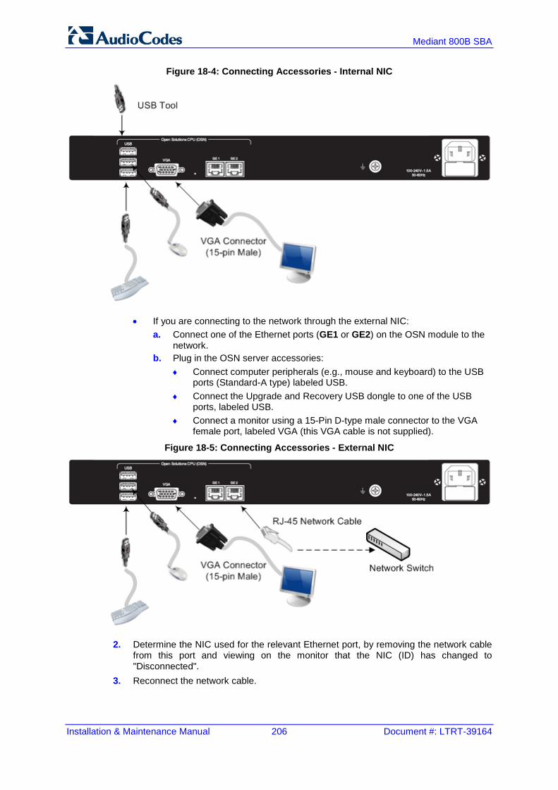
Installation & Maintenance Manual 206 Document #: LTRT-39164
Mediant 800B SBA
Figure 18-4: Connecting Accessories - Internal NIC
• If you are connecting to the network through the external NIC: a. Connect one of the Ethernet ports (GE1 or GE2) on the OSN module to the
network. b. Plug in the OSN server accessories:
♦ Connect computer peripherals (e.g., mouse and keyboard) to the USB ports (Standard-A type) labeled USB.
♦ Connect the Upgrade and Recovery USB dongle to one of the USB ports, labeled USB.
♦ Connect a monitor using a 15-Pin D-type male connector to the VGA female port, labeled VGA (this VGA cable is not supplied).
Figure 18-5: Connecting Accessories - External NIC
2. Determine the NIC used for the relevant Ethernet port, by removing the network cable from this port and viewing on the monitor that the NIC (ID) has changed to "Disconnected".
3. Reconnect the network cable.

Installation & Maintenance Manual 18. SBA Upgrade and Recovery
Version 6.8 207 Microsoft Lync Server
4. Do one of the following: • If you have a DHCP server in your network, note the IP address assigned to the
relevant Ethernet LAN port. • If you are not using a DHCP server, then assign a static IP address to the NIC of
the Ethernet LAN port. 5. Open a standard Web browser (Firefox, Google Chrome, or Internet Explorer 9 and
later is recommended), and then in the URL address field, enter the IP address that you determined above. The Survivable Branch Appliance Management Interface opens:
Figure 18-6: Welcome to SBA Screen
6. Log in with the default username ("Administrator") and password ("Pass123"), Select the “Yes, I accept the term and condition” checkbox and then click Login; the Home screen appears:
Figure 18-7: SBA Home Screen

Installation & Maintenance Manual 208 Document #: LTRT-39164
Mediant 800B SBA
7. Change the default IP address of the SBA Management Interface to suit your network environment (see Section 10.1 on page 75).

4
Part VIII Appendices


Installation & Maintenance Manual A. SBA Security Default Template
Version 6.8 211 Microsoft Lync Server
A SBA Security Default Template This appendix describes the AudioCodes provided default SBA security template (configured in Section 10.15.2 on page 117). The Microsoft SCW security configuration database utility was used to prepare this template. This utility contains information on the following: Server roles. See Section A.1 on page 211. Client features. See Section A.2 on page 213. Administration and other options. See Section A.3 on page 214. Services. See Section A.4 on page 215. Firewall rules. See Section A.5 on page 234.
A.1 Server Roles Each server role can be in one the following possible status: Installed and enabled Installed and disabled Not installed and disabled The following list details the server roles which must be installed and enabled on the SBA. The SCW uses the server role information to enable services and open ports in the local firewall.
Table A-1: Server Roles
Server Role Description
Application Server – Application Server Foundation
Application Server Foundation provides technologies for deploying and managing .NET Framework 3.0 applications. These technologies include Windows Presentation Foundation (WPF), Windows Communication Foundation (WCF), and Windows Workflow Foundation (WF). Application Server Foundation provides the means for delivering managed-code applications with seamless user experiences, secure communication, and the ability to model a range of business processes.
Application Server – Message Queuing Activation
Message Queuing Activation supports process activation through Message Queuing. Applications that use Message Queuing Activation can start and stop dynamically in response to work items that arrive over the network through Message Queuing.
Application Server – Named Pipes Activation
Named Pipes Activation supports process activation through named pipes. Applications that use Named Pipes Activation can start and stop dynamically in response to work items that arrive over the network through named pipes.
Application Server – TCP Activation
TCP Activation supports process activation through TCP. Applications that use TCP Activation can start and stop dynamically in response to work items that arrive over the network through TCP.
ASP.NET State Service The ASP.NET state service stores session state out of process from ASP.NET applications. It ensures that session state is preserved if an ASP.NET application is restarted and also makes session state available to multiple ASP.NET applications running in a Web farm.
Distributed Transactions The middle-tier application server can coordinate or participate in distributed transactions.
File Server A file server shares and stores files for users or applications.
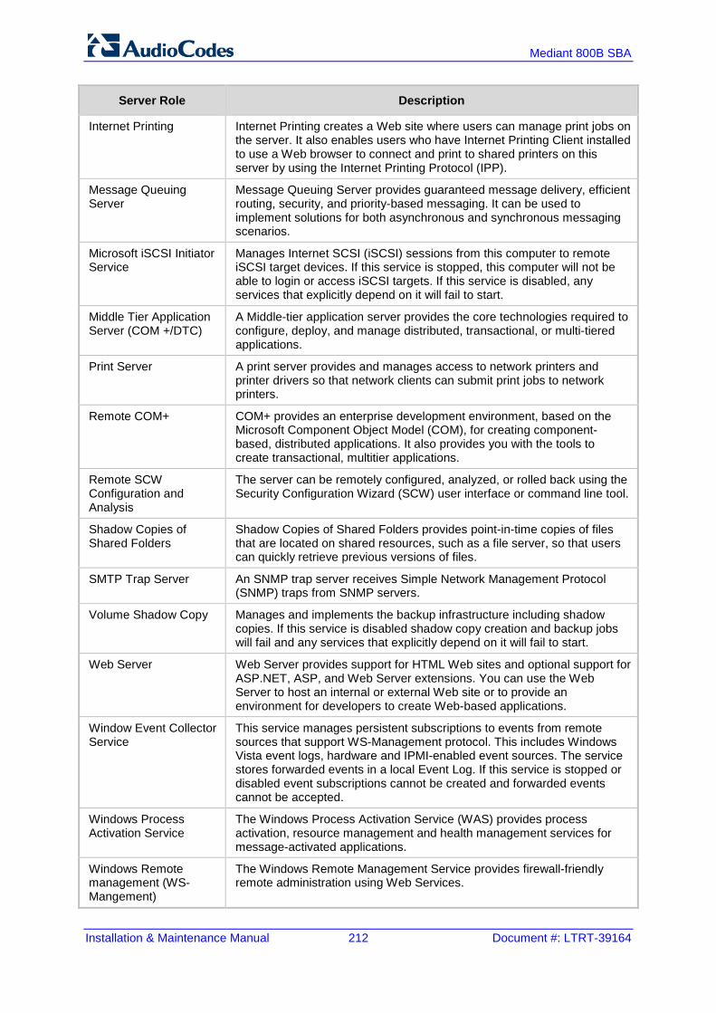
Installation & Maintenance Manual 212 Document #: LTRT-39164
Mediant 800B SBA
Server Role Description
Internet Printing Internet Printing creates a Web site where users can manage print jobs on the server. It also enables users who have Internet Printing Client installed to use a Web browser to connect and print to shared printers on this server by using the Internet Printing Protocol (IPP).
Message Queuing Server
Message Queuing Server provides guaranteed message delivery, efficient routing, security, and priority-based messaging. It can be used to implement solutions for both asynchronous and synchronous messaging scenarios.
Microsoft iSCSI Initiator Service
Manages Internet SCSI (iSCSI) sessions from this computer to remote iSCSI target devices. If this service is stopped, this computer will not be able to login or access iSCSI targets. If this service is disabled, any services that explicitly depend on it will fail to start.
Middle Tier Application Server (COM +/DTC)
A Middle-tier application server provides the core technologies required to configure, deploy, and manage distributed, transactional, or multi-tiered applications.
Print Server A print server provides and manages access to network printers and printer drivers so that network clients can submit print jobs to network printers.
Remote COM+ COM+ provides an enterprise development environment, based on the Microsoft Component Object Model (COM), for creating component-based, distributed applications. It also provides you with the tools to create transactional, multitier applications.
Remote SCW Configuration and Analysis
The server can be remotely configured, analyzed, or rolled back using the Security Configuration Wizard (SCW) user interface or command line tool.
Shadow Copies of Shared Folders
Shadow Copies of Shared Folders provides point-in-time copies of files that are located on shared resources, such as a file server, so that users can quickly retrieve previous versions of files.
SMTP Trap Server An SNMP trap server receives Simple Network Management Protocol (SNMP) traps from SNMP servers.
Volume Shadow Copy Manages and implements the backup infrastructure including shadow copies. If this service is disabled shadow copy creation and backup jobs will fail and any services that explicitly depend on it will fail to start.
Web Server Web Server provides support for HTML Web sites and optional support for ASP.NET, ASP, and Web Server extensions. You can use the Web Server to host an internal or external Web site or to provide an environment for developers to create Web-based applications.
Window Event Collector Service
This service manages persistent subscriptions to events from remote sources that support WS-Management protocol. This includes Windows Vista event logs, hardware and IPMI-enabled event sources. The service stores forwarded events in a local Event Log. If this service is stopped or disabled event subscriptions cannot be created and forwarded events cannot be accepted.
Windows Process Activation Service
The Windows Process Activation Service (WAS) provides process activation, resource management and health management services for message-activated applications.
Windows Remote management (WS-Mangement)
The Windows Remote Management Service provides firewall-friendly remote administration using Web Services.

Installation & Maintenance Manual A. SBA Security Default Template
Version 6.8 213 Microsoft Lync Server
A.2 Client Features Servers also act as clients to other servers. Each client feature can be in one the following possible status: Installed and enabled Installed and disabled Not installed and disabled The following list details only the client features that must be installed and enabled on the SBA.
Table A-2: Client Features
Client Feature Description
Background Intelligent Transfer Service (BITS) Transfers files in the background using idle network bandwidth.
DNS Client DNS clients, also known as resolvers, use the DNS (Domain Name System) protocol to send queries to DNS Servers to lookup the DNS name of a computer and retrieve information associated with the computer, such as its IP address or other services it provides. This process is called name resolution.
Domain Member A domain member is a computer that is joined to an Active Directory domain.
Microsoft Networking Client Creates and maintains client network connections to remote servers using the SMB protocol.
Time Synchronization The server regularly contacts a Network Time Protocol (NTP) server in order to accurately maintain its clock.
WINS Client A Windows Internet Name Service (WINS) client locates objects on a network using the NetBIOS Name Service (NBNS) protocol.

Installation & Maintenance Manual 214 Document #: LTRT-39164
Mediant 800B SBA
A.3 Administration and Other Options Each entry can be in one the following possible statuses: Installed and enabled Installed and disabled Not installed and disabled The following list details only the administration and other options that must be installed and enabled.
Table A-3: Administration and Other Options
Administration & Other Options Description
.NET Framework 3.0 Microsoft .NET Framework 3.0 combines the power of the .NET Framework 2.0 APIs with new technologies for building applications that offer appealing user interfaces, protect your customers’ personal identity information, enable seamless and secure communication, and provide the ability to model a range of business processes.
Local Application Installation Programs can be added, removed, or repaired on the server using the Windows Installer Service.
Message Queuing Multicasting Support Message Queuing Multicasting Support enables the queuing and sending of multicast messages to a multicast IP address.
Microsoft Fibre Channel Platform Registration Service
Registers the platform with all available Fibre Channel fabrics, and maintains the registrations.
Remote Desktop Services printer redirection Remote Desktop Services users can redirect print jobs to their local printers.
Smart Card Manages access to smart cards read by this computer.

Installation & Maintenance Manual A. SBA Security Default Template
Version 6.8 215 Microsoft Lync Server
A.4 Services The SBA device doesn’t require all of the default services. The services that are not required were disabled. Only the required services are enabled (either automatic or manual). The following list details the services that are enabled during startup – manually or automatically.
Table A-4: Services
Service Description Startup Default
Active Directory Certificate Services
Issues, manages, and removes X.509 certificates for applications such as S/MIME and SSL. If the service is stopped, certificates will not be issued. If this service is disabled, any services that explicitly depend on it will fail to start.
Automatic
Active Directory Domain Services
AD DS Domain Controller service. If this service is stopped, users will be unable to log on to the network. If this service is disabled, any services that explicitly depend on it will fail to start.
Automatic
AD FS Web Agent Authentication Service
The AD FS Web Agent Authentication Service validates incoming tokens and cookies.
Automatic
AdRmsLoggingService Sends logging messages to the logging database when logging is enabled for the Active Directory Rights Management Services role. If this service is disabled or stopped when logging is enabled, logging messages will be stored in local message queues and sent to the logging database when the service is started.
Automatic
Application Experience Processes application compatibility cache requests for applications as they are launched
Automatic
Application Host Helper Service Provides administrative services for IIS, for example configuration history and Application Pool account mapping. If this service is stopped, configuration history and locking down files or directories with Application Pool specific Access Control Entries will not work.
Automatic
Application Identity Determines and verifies the identity of an application. Disabling this service will prevent AppLocker from being enforced.
Manual
Application Information Facilitates the running of interactive applications with additional administrative privileges. If this service is stopped, users will be unable to launch applications with the additional administrative privileges they may require to perform desired user tasks.
Manual
Application Layer Gateway Service
Provides support for 3rd party protocol plug-ins for Internet Connection Sharing
Manual

Installation & Maintenance Manual 216 Document #: LTRT-39164
Mediant 800B SBA
Service Description Startup Default
Application Management Processes installation, removal, and enumeration requests for software deployed through the Group Policy. If this service is stopped, users will be unable to install, remove, or enumerate software deployed through the Group Policy. If this service is disabled, any services that explicitly depend on it will fail to start.
Manual
ASP.NET State Service Provides support for out-of-process session states for ASP.NET. If this service is stopped, out-of-process requests will not be processed. If this service is disabled, any services that explicitly depend on it will fail to start.
Automatic
AudioEndpointBuilder Manages audio devices for the Windows Audio service. If this service is stopped, audio devices and effects will not function properly. If this service is disabled, any services that explicitly depend on it will fail to start.
Manual
Audiosrv Manages audio for Windows-based programs. If this service is stopped, audio devices and effects will not function properly. If this service is disabled, any services that explicitly depend on it will fail to start.
Manual
Background Intelligent Transfer Service
Transfers files in the background using idle network bandwidth. If the service is disabled, then any applications that depend on BITS, such as Windows Update or MSN Explorer, will be unable to automatically download programs and other information.
Automatic
Base Filtering Engine The Base Filtering Engine (BFE) is a service that manages firewall and Internet Protocol security (IPsec) policies and implements user mode filtering. Stopping or disabling the BFE service will significantly reduce the security of the system. It will also result in unpredictable behavior in IPsec management and firewall applications.
Automatic
Block Level Backup Engine Service
Engine to perform block level backup and recovery of data.
Manual
BOAService _ Automatic
Certificate Propagation Copies user certificates and root certificates from smart cards into the current user's certificate store, detects when a smart card is inserted into a smart card reader, and, if required, installs the smart card Plug and Play minidriver.
Automatic
Client for NFS Enables this computer to access files on NFS shares.
Automatic
clr_optimization_v2.0.50727_I64 clr_optimization_v2.0.50727_I64 Manual

Installation & Maintenance Manual A. SBA Security Default Template
Version 6.8 217 Microsoft Lync Server
Service Description Startup Default
Cluster Service Enables servers to work together as a cluster to keep server-based applications highly available, regardless of individual component failures. If this service is stopped, clustering will be unavailable. If this service is disabled, any services that explicitly depend on it will fail to start.
Automatic
CNG Key Isolation The CNG key isolation service is hosted in the LSA process. The service provides key process isolation to private keys and associated cryptographic operations as required by the Common Criteria. The service stores and uses long-lived keys in a secure process complying with Common Criteria requirements.
Manual
COM+ Event System Supports System Event Notification Service (SENS), which provides automatic distribution of events to subscribing Component Object Model (COM) components. If the service is stopped, SENS will close and will not be able to provide logon and logoff notifications. If this service is disabled, any services that explicitly depend on it will fail to start.
Automatic
COM+ System Application Manages the configuration and tracking of Component Object Model (COM)+-based components. If the service is stopped, most COM+-based components will not function properly. If this service is disabled, any services that explicitly depend on it will fail to start.
Manual
Computer Browser Maintains an updated list of computers on the network and supplies this list to computers designated as browsers. If this service is stopped, this list will not be updated or maintained. If this service is disabled, any services that explicitly depend on it will fail to start.
Automatic
Credential Manager Provides secure storage and retrieval of credentials to users, applications and security service packages.
Manual
Cryptographic Services Provides four management services: Catalog Database Service, which confirms the signatures of Windows files and allows new programs to be installed; Protected Root Service, which adds and removes Trusted Root Certification Authority certificates from this computer; Automatic Root Certificate Update Service, which retrieves root certificates from Windows Update and enable scenarios such as SSL; and Key Service, which helps enroll this computer for certificates. If this service is stopped, these management services will not function properly. If this service is disabled, any services that explicitly depend on it will fail to start.
Automatic

Installation & Maintenance Manual 218 Document #: LTRT-39164
Mediant 800B SBA
Service Description Startup Default
DCOM Server Process Launcher
The DCOMLAUNCH service launches COM and DCOM servers in response to object activation requests. If this service is stopped or disabled, programs using COM or DCOM will not function properly. It is strongly recommended that you have the DCOMLAUNCH service up and running.
Automatic
Desktop Window Manager Session Manager
Provides Desktop Window Manager startup and maintenance services
Automatic
DFS Namespace Integrates disparate file shares into a single, logical namespace and manages these logical volumes.
Automatic
DFS Replication Replicates files among multiple PCs keeping them in sync. On the client, it is used to roam folders between PCs and on the server, it is used to provide high availability and local access across a wide area network (WAN). If the service is stopped, file replication does not occur, and the files on the server become out-of-date. If the service is disabled, any services that explicitly depend on it will not start.
Automatic
DHCP Client Registers and updates IP addresses and DNS records for this computer. If this service is stopped, this computer will not receive dynamic IP addresses and DNS updates. If this service is disabled, any services that explicitly depend on it will fail to start.
Automatic
DHCP Server Performs TCP/IP configuration for DHCP clients, including dynamic assignments of IP addresses, specification of the WINS and DNS servers, and connection-specific DNS names. If this service is stopped, the DHCP server will not perform TCP/IP configuration for clients. If this service is disabled, any services that explicitly depend on it will fail to start.
Automatic
Diagnostic Policy Service The Diagnostic Policy Service enables problem detection, troubleshooting and resolution for Windows components. If this service is stopped, diagnostics will no longer function.
Automatic
Diagnostic Service Host The Diagnostic Service Host is used by the Diagnostic Policy Service to host diagnostics that need to run in a Local Service context. If this service is stopped, any diagnostics that depend on it will no longer function.
Manual
Diagnostic System Host The Diagnostic System Host is used by the Diagnostic Policy Service to host diagnostics that need to run in a Local System context. If this service is stopped, any diagnostics that depend on it will no longer function.
Manual
Disk Defragmenter Provides Disk Defragmentation Capabilities. Manual
Distributed Link Tracking Client Maintains links between NTFS files within a computer or across computers in a network.
Automatic

Installation & Maintenance Manual A. SBA Security Default Template
Version 6.8 219 Microsoft Lync Server
Service Description Startup Default
Distributed Transaction Coordinator
Coordinates transactions that span multiple resource managers, such as databases, message queues, and file systems. If this service is stopped, these transactions will fail. If this service is disabled, any services that explicitly depend on it will fail to start.
Automatic
DNS Client The DNS Client service (dnscache) caches Domain Name System (DNS) names and registers the full computer name for this computer. If the service is stopped, DNS names will continue to be resolved. However, the results of DNS name queries will not be cached and the computer's name will not be registered. If the service is disabled, any services that explicitly depend on it will fail to start.
Automatic
DNS Server The DNS server service stores and resolves DNS names of clients in order to enable computers to locate other computers and services. If the service is stopped or disabled, DNS updates and queries from clients sent to the local computer will not be processed. Any services that explicitly depend on the DNS server on the local computer will start to see failures.
Automatic
Encrypting File System (EFS) Provides the core file encryption technology used to store encrypted files on NTFS file system volumes. If this service is stopped or disabled, applications will be unable to access encrypted files.
Manual
Extensible Authentication Protocol
The Extensible Authentication Protocol (EAP) service provides network authentication in such scenarios as 802.1x wired and wireless, VPN, and Network Access Protection (NAP). EAP also provides application programming interfaces (APIs) that are used by network access clients, including wireless and VPN clients, during the authentication process. If you disable this service, this computer is prevented from accessing networks that require EAP authentication.
Manual
Fax Enables you to send and receive faxes, using fax resources available on this computer or on the network.
Automatic
File Server Resource Manager Provides services for quota and file screen management.
Automatic
File Server Storage Reports Manager
Provides services for configuration, scheduling, and generation of storage reports.
Manual
FTP Publishing Service Enables this server to be a File Transfer Protocol (FTP) server. If this service is stopped, the server cannot function as an FTP server. If this service is disabled, any services that explicitly depend on it will fail to start.
Manual

Installation & Maintenance Manual 220 Document #: LTRT-39164
Mediant 800B SBA
Service Description Startup Default
Function Discovery Provider Host
The FDPHOST service hosts the Function Discovery (FD) network discovery providers. These FD providers supply network discovery services for the Simple Services Discovery Protocol (SSDP) and Web Services – Discovery (WS-D) protocol. Stopping or disabling the FDPHOST service will disable network discovery for these protocols when using FD. When this service is unavailable, network services using FD and relying on these discovery protocols will be unable to find network devices or resources.
Manual
Function Discovery Resource Publication
Publishes this computer and resources attached to this computer so they can be discovered over the network. If this service is stopped, network resources will no longer be published and they will not be discovered by other computers on the network.
Manual
Group Policy Client This service is responsible for applying settings configured by administrators for the computer and users through the Group Policy component. If this service is stopped or disabled, the settings will not be applied and applications and components will not be manageable through Group Policy. Any components or applications that depend on the Group Policy component might not be functional if the service is stopped or disabled.
Automatic
Health Key and Certificate Management
Provides X.509 certificate and key management services for the Network Access Protection Agent (NAPAgent). Enforcement technologies that use X.509 certificates may not function properly without this service.
Manual
Hyper-V Image Management Service
Provides Image Management servicing for Hyper-V. Automatic
Hyper-V Networking Management Service
Provides Hyper-V Networking WMI management. Automatic
Hyper-V Virtual Machine Management
Management service for Hyper-V, provides service to run multiple virtual machines.
Automatic
IAS JET Database Access IASJet Manual
IIS Admin Service Enables this server to administer metabase FTP services. If this service is stopped, the server will be unable to run metabase or FTP sites. If this service is disabled, any services that explicitly depend on it will fail to start.
Automatic

Installation & Maintenance Manual A. SBA Security Default Template
Version 6.8 221 Microsoft Lync Server
Service Description Startup Default
IKE and AuthIP IPsec Keying Modules
The IKEEXT service hosts the Internet Key Exchange (IKE) and Authenticated Internet Protocol (AuthIP) keying modules. These keying modules are used for authentication and key exchange in Internet Protocol security (IPsec). Stopping or disabling the IKEEXT service will disable IKE and AuthIP key exchange with peer computers. IPsec is typically configured to use IKE or AuthIP; therefore, stopping or disabling the IKEEXT service might result in an IPsec failure and might compromise the security of the system. It is strongly recommended that you have the IKEEXT service running.
Automatic
Indexing Service Indexes contents and properties of files on local and remote computers provide rapid access to files through flexible querying language.
Automatic
Intel(R) Capability Licensing Service Interface
Version: 1.23.605.1 Automatic
Intel(R) Dynamic Application Loader Host Interface Service
Intel(R) Dynamic Application Loader Host Interface Service - allows applications to access the local Intel (R) DAL.
Automatic
Intel(R) Management and Security Application Local Management Service
Allows applications to access the local Intel(R) Management and Security Application using its locally-available selected network interfaces.
Automatic
Intel(R) Management and Security Application User Notification Service
Intel(R) Management and Security Application User Notification Service - Updates the Windows Event Log with notifications of pre defined events received from the local Intel(R) Management and Security Application Device.
Automatic
Intel(R) PROSet Monitoring Service
The Intel(R) PROSet Monitoring Service actively monitors changes to the system and updates affected network devices to keep them running in optimal condition. Stopping this service may negatively affect the performance of the network devices on the system.
Automatic
Interactive Services Detection Enables user notification of user input for interactive services, which enables access to dialogs created by interactive services when they appear. If this service is stopped, notifications of new interactive service dialogs will no longer function and there may no longer be access to interactive service dialogs. If this service is disabled, both notifications of and access to new interactive service dialogs will no longer function.
Manual
Intersite Messaging Enables messages to be exchanged between computers running Windows Server sites. If this service is stopped, messages will not be exchanged, nor will site routing information be calculated for other services. If this service is disabled, any services that explicitly depend on it will fail to start.
Automatic

Installation & Maintenance Manual 222 Document #: LTRT-39164
Mediant 800B SBA
Service Description Startup Default
IP Helper Provides tunnel connectivity using IPv6 transition technologies (6to4, ISATAP, Port Proxy, and Teredo), and IP-HTTPS. If this service is stopped, the computer will not have the enhanced connectivity benefits that these technologies offer.
Automatic
IPsec Policy Agent Internet Protocol security (IPsec) supports network-level peer authentication, data origin authentication, data integrity, data confidentiality (encryption), and replay protection. This service enforces IPsec policies created through the IP Security Policies snap-in or the command-line tool "netsh ipsec". If you stop this service, you may experience network connectivity issues if your policy requires that connections use IPsec. Also,remote management of Windows Firewall is not available when this service is stopped.
Automatic
Kerberos Key Distribution Center
On domain controllers this service enables users to log on to the network using the Kerberos authentication protocol. If this service is stopped on a domain controller, users will be unable to log on to the network. If this service is disabled, any services that explicitly depend on it will fail to start.
Automatic
KtmRm for Distributed Transaction Coordinator
Coordinates transactions between the Distributed Transaction Coordinator (MSDTC) and the Kernel Transaction Manager (KTM). If it is not needed, it is recommended that this service remains stopped. If it is needed, both MSDTC and KTM will start this service automatically. If this service is disabled, any MSDTC transaction interacting with a Kernel Resource Manager will fail and any services that explicitly depend on it will fail to start.
Automatic
Link-Layer Topology Discovery Mapper
Creates a Network Map, consisting of PC and device topology (connectivity) information, and metadata describing each PC and device. If this service is disabled, the Network Map will not function properly.
Manual
Lync Server Front-End Lync Server Front-End Automatic
Lync Server Mediation Lync Server Mediation Automatic
Lync Server Replica Replicator Agent
Lync Server Replica Replicator Agent Automatic
Message Queuing Provides a messaging infrastructure and development tool for creating distributed messaging applications for Windows-based networks and programs. If this service is stopped, distributed messages will be unavailable. If this service is disabled, any services that explicitly depend on it will fail to start.
Automatic
Message Queuing Downlevel Client Support
Allows MSMQ 2.0 clients to access MSMQ Active Directory features
Automatic

Installation & Maintenance Manual A. SBA Security Default Template
Version 6.8 223 Microsoft Lync Server
Service Description Startup Default
Message Queuing Triggers Provides rule-based monitoring of messages arriving in a Message Queuing queue and, when the conditions of a rule are satisfied, invokes a COM component or a stand-alone executable program to process the message.
Automatic
Microsoft .NET Framework NGEN v2.0.50727_X64
Microsoft .NET Framework NGEN Manual
Microsoft .NET Framework NGEN v2.0.50727_X86
Microsoft .NET Framework NGEN Manual
Microsoft Fibre Channel Platform Registration Service
Registers the platform with all available Fibre Channel fabrics, and maintains the registrations.
Automatic
Microsoft iSCSI Initiator Service
Manages Internet SCSI (iSCSI) sessions from this computer to remote iSCSI target devices. If this service is stopped, this computer will not be able to login or access iSCSI targets. If this service is disabled, any services that explicitly depend on it will fail to start.
Manual
Microsoft iSNS Server Maintains a database of iSNS client registrations and notifies clients when changes are made to the database.
Automatic
Microsoft Software Shadow Copy Provider
Manages software-based volume shadow copies taken by the Volume Shadow Copy service. If this service is stopped, software-based volume shadow copies cannot be managed. If this service is disabled, any services that explicitly depend on it will fail to start.
Manual
Net.Msmq Listener Adapter Receives activation requests over the net.msmq and msmq.formatname protocols and passes them to the Windows Process Activation Service.
Automatic
Net.Pipe Listener Adapter Receives activation requests over the net.pipe protocol and passes them to the Windows Process Activation Service.
Automatic
Net.Tcp Listener Adapter Receives activation requests over the net.tcp protocol and passes them to the Windows Process Activation Service.
Automatic
Network Access Protection Agent
The Network Access Protection (NAP) agent service collects and manages health information for client computers on a network. Information collected by NAP agent is used to make sure that the client computer has the required software and settings. If a client computer is not compliant with health policy, it can be provided with restricted network access until its configuration is updated. Depending on the configuration of health policy, client computers might be automatically updated so that users quickly regain full network access without having to manually update their computer.
Manual

Installation & Maintenance Manual 224 Document #: LTRT-39164
Mediant 800B SBA
Service Description Startup Default
Network Connections Manages objects in the Network and Dial-Up Connections folder, in which you can view both local area network and remote connections.
Manual
Network List Service Identifies the networks to which the computer has connected, collects and stores properties for these networks, and notifies applications when these properties change.
Automatic
Network Location Awareness Collects and stores configuration information for the network and notifies programs when this information is modified. If this service is stopped, configuration information might be unavailable. If this service is disabled, any services that explicitly depend on it will fail to start.
Automatic
Network Policy Server Manages authentication, authorization, auditing and accounting for virtual private network (VPN), dial-up, 802.1x wireless or Ethernet switch connection attempts sent by access servers that are compatible with the IETF RADIUS protocol. If this service is stopped, users might be unable to obtain a VPN, dial-up, wireless, or Ethernet connection to the network. If this service is disabled, any services that explicitly depend on it will fail to start.
Automatic
Network Store Interface Service
This service delivers network notifications (e.g. interface addition/deleting etc) to user mode clients. Stopping this service will cause loss of network connectivity. If this service is disabled, any other services that explicitly depend on this service will fail to start.
Automatic
Online Responder Service Enables the Online Certificate Status Protocol (OCSP) services for a PKI based applications such as secure e-mail, smartcard logon, secure web servers. If this service is stopped or disabled then the revocation services may not be available thereby causing authentication or application failures.
Automatic
Peer Name Resolution Protocol
Enables Serverless Peer Name Resolution over the Internet. If disabled, some Peer to Peer and Collaborative applications, such as Windows Meetings, may not function.
Manual
Peer Networking Identity Manager
Provides Identity service for Peer Networking. Manual
Performance Counter DLL Host
Enables remote users and 64-bit processes to query performance counters provided by 32-bit DLLs. If this service is stopped, only local users and 32-bit processes will be able to query performance counters provided by 32-bit DLLs.
Manual

Installation & Maintenance Manual A. SBA Security Default Template
Version 6.8 225 Microsoft Lync Server
Service Description Startup Default
Performance Logs & Alerts Performance logs and alerts collect performance data from local or remote computers based on pre-configured schedule parameters, then writes the data to a log or triggers an alert. If this service is stopped, performance information will not be collected. If this service is disabled, any services that explicitly depend on it will fail to start.
Manual
Plug and Play Enables a computer to recognize and adapt to hardware changes with little or no user input. Stopping or disabling this service will result in system instability.
Automatic
PNRP Machine Name Publication Service
This service publishes a machine name using the Peer Name Resolution Protocol. Configuration is managed through the netsh context 'p2p pnrp peer'.
Manual
Portable Device Enumerator Service
Enforces group policy for removable mass-storage devices. Enables applications such as Windows Media Player and Image Import Wizard to transfer and synchronize content using removable mass-storage devices.
Manual
Power Manages power policy and power policy notification delivery.
Automatic
Print Spooler Loads files to memory for later printing. Automatic
Problem Reports and Solutions Control Panel Support
This service provides support for viewing, sending and deletion of system-level problem reports for the Problem Reports and Solutions control panel.
Manual
Protected Storage Provides protected storage for sensitive data, such as passwords, to prevent access by unauthorized services, processes, or users.
Manual
Quality Windows Audio Video Experience
Quality Windows Audio Video Experience (qWave) is a networking platform for Audio Video (AV) streaming applications on IP home networks. qWave enhances AV streaming performance and reliability by ensuring network quality-of-service (QoS) for AV applications. It provides mechanisms for admission control, run time monitoring and enforcement, application feedback, and traffic prioritization.
Manual
Remote Access Auto Connection Manager
Creates a connection to a remote network whenever a program references a remote DNS or NetBIOS name or address.
Manual
Remote Access Connection Manager
Manages dial-up and virtual private network (VPN) connections from this computer to the Internet or other remote networks. If this service is disabled, any services that explicitly depend on it will fail to start.
Manual
Remote Access Quarantine Agent
Removes validated remote access client from the quarantine network.
Manual

Installation & Maintenance Manual 226 Document #: LTRT-39164
Mediant 800B SBA
Service Description Startup Default
Remote Desktop Configuration Remote Desktop Configuration service (RDCS) is responsible for all Remote Desktop Services and Remote Desktop related configuration and session maintenance activities that require SYSTEM context. These include per-session temporary folders, RD themes, and RD certificates.
Automatic
Remote Desktop Gateway Provides secure remote connectivity to remote computers on your corporate network, from anywhere on the Internet. If this service is stopped, connections to remote computers cannot be made through this Remote Desktop Gateway server.
Automatic
Remote Desktop Licensing Provides registered licenses for Remote Desktop Services clients. If this service is stopped, the server will be unavailable to issue Remote Desktop Services client access licenses to clients when they are requested.
Automatic
Remote Desktop Services Allows users to connect interactively to a remote computer. Remote Desktop and Remote Desktop Session Host Server depend on this service. To prevent remote use of this computer, clear the checkboxes on the Remote tab of the System properties control panel item.
Automatic
Remote Desktop Services UserMode Port Redirector
Allows the redirection of Printers/Drives/Ports for RDP connections.
Manual
Remote Desktop Services Connection Broker
Enables a user connection request to be routed to the appropriate Remote Desktop Session Host in a cluster. If this service is stopped, connection requests will be routed to the first available server.
Automatic
Remote Packet Capture Protocol v.0 (experimental)
Allows to capture traffic on this machine from a remote machine.
Manual
Remote Packet Capture Protocol v.0 (experimental)
Allows to capture traffic on this machine from a remote machine.
Manual
Remote Procedure Call (RPC)
The RPCSS service is the Service Control Manager for COM and DCOM servers. It performs object activations requests, object exporter resolutions and distributed garbage collection for COM and DCOM servers. If this service is stopped or disabled, programs using COM or DCOM will not function properly. It is strongly recommended that you have the RPCSS service running.
Automatic
Remote Procedure Call (RPC) Locator
In Windows 2003 and earlier versions of Windows, the Remote Procedure Call (RPC) Locator service manages the RPC name service database. In Windows Vista and later versions of Windows, this service does not provide any functionality and is present for application compatibility.
Manual

Installation & Maintenance Manual A. SBA Security Default Template
Version 6.8 227 Microsoft Lync Server
Service Description Startup Default
Remote Registry Enables remote users to modify registry settings on this computer. If this service is stopped, the registry can be modified only by users on this computer. If this service is disabled, any services that explicitly depend on it will fail to start.
Automatic
Removable Storage Manages and catalogs removable media and operates automated removable media devices. If this service is stopped, programs that are dependent on Removable Storage, such as Backup and Remote Storage, will operate more slowly. If this service is disabled, any services that explicitly depend on it will fail to start.
Manual
Resultant Set of Policy Provider
Provides a network service that processes requests to simulate application of Group Policy settings for a target user or computer in various situations and computes the Resultant Set of Policy settings.
Manual
Secondary Logon Enables starting processes under alternate credentials. If this service is stopped, this type of logon access will be unavailable. If this service is disabled, any services that explicitly depend on it will fail to start.
Automatic
Secure Socket Tunneling Protocol Service
Provides support for the Secure Socket Tunneling Protocol (SSTP) to connect to remote computers using VPN. If this service is disabled, users will not be able to use SSTP to access remote servers.
Manual
Security Accounts Manager The startup of this service signals other services that the Security Accounts Manager (SAM) is ready to accept requests. Disabling this service will prevent other services in the system from being notified when the SAM is ready, which may in turn cause those services to fail to start correctly. This service should not be disabled.
Automatic
Server Supports file, print, and named-pipe sharing over the network for this computer. If this service is stopped, these functions will be unavailable. If this service is disabled, any services that explicitly depend on it will fail to start.
Automatic
Server for NFS Enables a Windows based computer to act as an NFS Server.
Automatic
Shell Hardware Detection Provides notifications for AutoPlay hardware events. Automatic
Simple Mail Transfer Protocol (SMTP)
Transports electronic mail across the network. Manual
Simple TCP/IP Services Supports the following TCP/IP services: Character Generator, Daytime, Discard, Echo, and Quote of the Day.
Automatic

Installation & Maintenance Manual 228 Document #: LTRT-39164
Mediant 800B SBA
Service Description Startup Default
Smart Card Manages access to smart cards read by this computer. If this service is stopped, this computer will be unable to read smart cards. If this service is disabled, any services that explicitly depend on it will fail to start.
Automatic
SNMP Service Enables Simple Network Management Protocol (SNMP) requests to be processed by this computer. If this service is stopped, the computer will be unable to process SNMP requests.
Automatic
SNMP Trap Receives trap messages generated by local or remote Simple Network Management Protocol (SNMP) agents and forwards the messages to SNMP management programs running on this computer. If this service is stopped, SNMP-based programs on this computer will not receive SNMP trap messages. If this service is disabled, any services that explicitly depend on it will fail to start.
Manual
Software Protection Enables the download, installation and enforcement of digital licenses for Windows and Windows applications. If the service is disabled, the operating system and licensed applications may run in a notification mode. It is strongly recommended that you not disable the Software Protection service.
Automatic
Special Administration Console Helper
Allows administrators to remotely access a command prompt using Emergency Management Services.
Manual
SPP Notification Service Provides Software Licensing activation and notification
Manual
SQL Active Directory Helper Service
Enables integration with Active Directories Automatic
SQL Server (RTCLOCAL) Provides storage, processing and controlled access of data, and rapid transaction processing.
Automatic
SQL Server Agent (RTCLOCAL)
Executes jobs, monitors SQL Server, fires alerts, and allows automation of some administrative tasks.
Automatic
SQL Server Browser Provides SQL Server connection information to client computers.
Automatic
SQL Server VSS Writer Provides the interface to backup/restore Windows internal database through the Windows VSS infrastructure.
Automatic
SSDP Discovery Discovers networked devices and services that use the SSDP discovery protocol, such as UPnP devices. Also announces SSDP devices and services running on the local computer. If this service is stopped, SSDP-based devices will not be discovered. If this service is disabled, any services that explicitly depend on it will fail to start.
Manual
System Event Notification Service
Monitors system events and notifies subscribers to COM+ Event System of these events.
Automatic

Installation & Maintenance Manual A. SBA Security Default Template
Version 6.8 229 Microsoft Lync Server
Service Description Startup Default
Task Scheduler Enables a user to configure and schedule automated tasks on this computer. The service also hosts multiple Windows system-critical tasks. If this service is stopped or disabled, these tasks will not be run at their scheduled times. If this service is disabled, any services that explicitly depend on it will fail to start.
Automatic
TCP/IP NetBIOS Helper Provides support for the NetBIOS over TCP/IP (NetBT) service and NetBIOS name resolution for clients on the network, therefore enabling users to share files, print, and log on to the network. If this service is stopped, these functions might be unavailable. If this service is disabled, any services that explicitly depend on it will fail to start.
Automatic
TCP/IP Print Server Enables TCP/IP-based printing using the Line Printer Daemon protocol. If this service is stopped, TCP/IP-based printing will be unavailable. If this service is disabled, any services that explicitly depend on it will fail to start.
Automatic
Telephony Provides Telephony API (TAPI) support for programs that control telephony devices on the local computer and, through the LAN, on servers that are also running the service.
Manual
TPM Base Services Enables access to the Trusted Platform Module (TPM), which provides hardware-based cryptographic services to system components and applications. If this service is stopped or disabled, applications will be unable to use keys protected by the TPM.
Manual
UPnP Device Host Allows UPnP devices to be hosted on this computer. If this service is stopped, any hosted UPnP devices will stop functioning and no additional hosted devices can be added. If this service is disabled, any services that explicitly depend on it will fail to start.
Automatic
User Profile Service This service is responsible for loading and unloading user profiles. If this service is stopped or disabled, users will no longer be able to successfully logon or logoff, applications may have problems accessing users' data, and components registered to receive profile event notifications will not receive them.
Automatic
Virtual Disk Provides management services for disks, volumes, file systems, and storage arrays.
Manual
Volume Shadow Copy Manages and implements Volume Shadow Copies used for backup and other purposes. If this service is stopped, shadow copies will be unavailable for backup and the backup may fail. If this service is disabled, any services that explicitly depend on it will fail to start.
Manual

Installation & Maintenance Manual 230 Document #: LTRT-39164
Mediant 800B SBA
Service Description Startup Default
Web Client Enables Windows-based programs to create, access, and modify Internet-based files. If this service is stopped, these functions will not be available. If this service is disabled, any services that explicitly depend on it will fail to start.
Automatic
Web Management Service The Web Management Service enables remote and delegated management capabilities for administrators to manage for the Web server, sites and applications present on this machine.
Automatic
Windows CardSpace Securely enables the creation, management, and disclosure of digital identities.
Manual
Windows Color System The WcsPlugInService service hosts third-party Windows Color System color device model and gamut map model plug-in modules. These plug-in modules are vendor-specific extensions to the Windows Color System baseline color device and gamut map models. Stopping or disabling the WcsPlugInService service will disable this extensibility feature, and the Windows Color System will use its baseline model processing rather than the vendor's desired processing. This might result in inaccurate color rendering.
Automatic
Windows Driver Foundation - User-mode Driver Framework
Manages user-mode driver host processes. Manual
Windows Error Reporting Service
Allows errors to be reported when programs stop working or responding and allows existing solutions to be delivered. Also allows logs to be generated for diagnostic and repair services. If this service is stopped, error reporting might not work correctly and results of diagnostic services and repairs might not be displayed.
Automatic
Windows Event Collector This service manages persistent subscriptions to events from remote sources that support WS-Management protocol. This includes Windows Vista event logs, hardware and IPMI-enabled event sources. The service stores forwarded events in a local Event Log. If this service is stopped or disabled event subscriptions cannot be created and forwarded events cannot be accepted.
Manual
Windows Event Log This service manages events and event logs. It supports logging events, querying events, subscribing to events, archiving event logs, and managing event metadata. It can display events in both XML and plain text format. Stopping this service may compromise security and reliability of the system.
Automatic
Windows Firewall Windows Firewall helps protect your computer by preventing unauthorized users from gaining access to your computer through the Internet or a network.
Automatic

Installation & Maintenance Manual A. SBA Security Default Template
Version 6.8 231 Microsoft Lync Server
Service Description Startup Default
Windows Font Cache Service Optimizes performance of applications by caching commonly used font data. Applications will start this service if it is not already running. It can be disabled, though doing so will degrade application performance.
Automatic
Windows Installer Adds, modifies, and removes applications provided as a Windows Installer (*.msi) package. If this service is disabled, any services that explicitly depend on it will fail to start.
Manual
Windows Internal Database Windows Internal Database uses SQL Server 2005 Embedded Edition (Windows) as a relational data store for Windows roles and features only, such as Windows Sharepoint Services, Active Directory Rights Management Services, UDDI Services, Windows Server Update Services, and Windows System Resources Manager.
Automatic
Windows Management Instrumentation
Provides a common interface and object model to access management information about operating system, devices, applications and services. If this service is stopped, most Windows-based software will not function properly. If this service is disabled, any services that explicitly depend on it will fail to start.
Automatic
Windows Modules Installer Enables installation, modification, and removal of Windows updates and optional components. If this service is disabled, install or uninstall of Windows updates might fail for this computer.
Manual
Windows Presentation Foundation Font Cache 3.0.0.0
Optimizes performance of Windows Presentation Foundation (WPF) applications by caching commonly used font data. WPF applications will start this service if it is not already running. It can be disabled, though doing so will degrade the performance of WPF applications.
Manual
Windows Process Activation Service
The Windows Process Activation Service (WAS) provides process activation, resource management and health management services for message-activated applications.
Automatic

Installation & Maintenance Manual 232 Document #: LTRT-39164
Mediant 800B SBA
Service Description Startup Default
Windows Remote Management (WS-Management)
Windows Remote Management (WinRM) service implements the WS-Management protocol for remote management. WS-Management is a standard web services protocol used for remote software and hardware management. The WinRM service listens on the network for WS-Management requests and processes them. The WinRM Service needs to be configured with a listener using winrm.cmd command line tool or through Group Policy in order for it to listen over the network. The WinRM service provides access to WMI data and enables event collection. Event collection and subscription to events require that the service is running. WinRM messages use HTTP and HTTPS as transports. The WinRM service does not depend on IIS but is preconfigured to share a port with IIS on the same machine. The WinRM service reserves the /wsman URL prefix. To prevent conflicts with IIS, administrators should ensure that any websites hosted on IIS do not use the /wsman URL prefix.
Automatic
Windows Search Provides content indexing and property caching for file, email and other content (through extensibility APIs). The service responds to file and email notifications to index modified content. If the service is stopped or disabled, the Explorer will not be able to display virtual folder views of items, and search in the Explorer will fall back to item-by-item slow search.
Automatic
Windows SharePoint Services Timer
Sends notifications and performs scheduled tasks for Windows SharePoint Services
Automatic
Windows SharePoint Services Tracing
Manages trace output Automatic
Windows SharePoint Services VSS Writer
Windows SharePoint Services VSS Writer Manual
Windows System Resource Manager
Assigns computer resources to multiple applications running on Windows Vista Server. If this service is stopped or disabled, no management will occur, no accounting data will be collected, and the administrator will not be able to administer Windows System Resource Manager.
Automatic
Windows Time Maintains date and time synchronization on all clients and servers in the network. If this service is stopped, date and time synchronization will be unavailable. If this service is disabled, any services that explicitly depend on it will fail to start.
Automatic
Windows Update Enables the detection, download, and installation of updates for Windows and other programs. If this service is disabled, users of this computer will not be able to use Windows Update or its automatic updating feature, and programs will not be able to use the Windows Update Agent (WUA) API.
Disable

Installation & Maintenance Manual A. SBA Security Default Template
Version 6.8 233 Microsoft Lync Server
Service Description Startup Default
WinHTTP Web Proxy Auto-Discovery Service
WinHTTP implements the client HTTP stack and provides developers with a Win32 API and COM Automation component for sending HTTP requests and receiving responses. In addition, WinHTTP provides support for auto-discovering a proxy configuration through its implementation of the Web Proxy Auto-Discovery (WPAD) protocol.
Manual
WINS Manages the Windows Internet Name Service (WINS), which translates NetBIOS computer names to IP addresses.
Automatic
Wired AutoConfig The Wired AutoConfig (DOT3SVC) service is responsible for performing IEEE 802.1X authentication on Ethernet interfaces. If your current wired network deployment enforces 802.1X authentication, the DOT3SVC service should be configured to run for establishing Layer 2 connectivity and/or providing access to network resources. Wired networks that do not enforce 802.1X authentication are unaffected by the DOT3SVC service.
Manual
WMI Performance Adapter Provides performance library information from Windows Management Instrumentation (WMI) providers to clients on the network. This service only runs when Performance Data Helper is activated.
Manual
Workstation Creates and maintains client network connections to remote servers using the SMB protocol. If this service is stopped, these connections will be unavailable. If this service is disabled, any services that explicitly depend on it will fail to start.
Automatic
World Wide Web Publishing Service
Provides Web connectivity and administration through the Internet Information Services Manager.
Automatic

Installation & Maintenance Manual 234 Document #: LTRT-39164
Mediant 800B SBA
A.5 Windows Update Policy Note the following in reference to Windows Update Policy: AudioCodes is obligated to test and approve all SBA Cumulative Updates (CU) within
1 month of Microsoft releasing them. AudioCodes ships all SBAs with the Windows Update service disabled as default
(Never check for updates (not recommended). AudioCodes does not test (as a rule) every Windows Update released by Microsoft. In case customers wish to enable the Windows Update service- Install Updates
automatically (recommended) (according to their corporate update policy), they can verify the updates, based upon Microsoft’s recommendations.
A.6 Firewall Rules This section describes the firewall rules that are used in the SBA deployment. These include the following: Default SBA internal firewall rules (see below) SBA network firewall settings (see Section A.6.2)
Note: Many firewall rules are required for normal SBA operation. The listing is extensive and therefore not all of the relevant firewall rules are listed in the document. To retrieve the full list of the firewall rules – open the scw_sba_W14 XML file with the SCW tool and open the firewall.
A.6.1 Default SBA Internal Firewall Rules The table below describes the default SBA internal firewall rules.
Table A-5: Firewall Rules
Firewall Rule Description Protocol Keyword Direction Program/
Service Local Ports Remote Ports
Allow inbound connections for service: RTCMEDSRV for protocol: TCP
_ TCP Inbound RTCMEDSRV
_ _
Allow inbound connections for service: SQLBrowser for protocol: UDP
_ UDP Inbound SQLBrowser
_ _
Allow inbound connections for service: MSSQL$RTCLOCAL for protocol: TCP
_ TCP Inbound MSSQL$RTCLOCAL
_ _

Installation & Maintenance Manual A. SBA Security Default Template
Version 6.8 235 Microsoft Lync Server
Firewall Rule Description Protocol Keyword Direction Program/
Service Local Ports Remote Ports
Allow inbound connections for service: RtcSrv for protocol: TCP
_ TCP Inbound RtcSrv _ _
Core Networking - Dynamic Host Configuration Protocol (DHCP-In)
Allows DHCP (Dynamic Host Configuration Protocol) messages for stateful auto-configuration.
UDP Inbound dhcp 68 67
Core Networking - Dynamic Host Configuration Protocol (DHCP-Out)
Allows DHCP (Dynamic Host Configuration Protocol) messages for stateful auto-configuration
UDP Outbound
dhcp 68 67
Core Networking - DNS (UDP-Out)
Outbound rule to allow DNS requests. DNS responses based on requests that matched this rule will be permitted regardless of source address. This behavior is classified as loose source mapping. [LSM] [UDP 53]
UDP Outbound
dnscache _ 53

Installation & Maintenance Manual 236 Document #: LTRT-39164
Mediant 800B SBA
Firewall Rule Description Protocol Keyword Direction Program/
Service Local Ports Remote Ports
Core Networking - Group Policy (LSASS-Out) Description: . Group: Core Networking Protocol Keyword: TCP Direction: Outbound Program: %systemroot%\system32\lsass.exe Enabled: True Action: AllowConnections Profiles: Domain
Outbound rule to allow remote LSASS traffic for Group Policy updates [TCP]
TCP Outbound
lsass.exe _ _
Core Networking - Group Policy (NP-Out)
Core Networking - Group Policy (NP-Out)
TCP Outbound
_ _ 445
Core Networking - Group Policy (TCP-Out)
Outbound rule to allow remote RPC traffic for Group Policy
TCP Outbound
_ _ _
Core Networking - Destination Unreachable Fragmentation Needed (ICMPv4-In)
Destination Unreachable Fragmentation Needed error messages are sent from any node that a packet traverses which is unable to forward the packet because fragmentation was needed and the don’t fragment bit was set.
ICMP_V4
Inbound _ _ _

Installation & Maintenance Manual A. SBA Security Default Template
Version 6.8 237 Microsoft Lync Server
Firewall Rule Description Protocol Keyword Direction Program/
Service Local Ports Remote Ports
Core Networking - Destination Unreachable (ICMPv6-In)
Destination Unreachable error messages are sent from any node that a packet traverses which is unable to forward the packet for any reason except congestion.
ICMP_V6
Inbound _ _ _
Core Networking - Multicast Listener Done (ICMPv6-In)
Multicast Listener Done messages inform local routers that there are no longer any members remaining for a specific multicast address on the subnet.
ICMP_V6
Inbound _ _ _
Core Networking - Multicast Listener Done (ICMPv6-Out)
Multicast Listener Done messages inform local routers that there are no longer any members remaining for a specific multicast address on the subnet
ICMP_V6
Outbound
_ _ _

Installation & Maintenance Manual 238 Document #: LTRT-39164
Mediant 800B SBA
Firewall Rule Description Protocol Keyword Direction Program/
Service Local Ports Remote Ports
Core Networking - Multicast Listener Query (ICMPv6-In)
An IPv6 multicast-capable router uses the Multicast Listener Query message to query a link for multicast group membership
ICMP_V6
Inbound _ _ _
Core Networking - Multicast Listener Query (ICMPv6-Out)
An IPv6 multicast-capable router uses the Multicast Listener Query message to query a link for multicast group membership
ICMP_V6
Outbound
_ _ _
Core Networking - Multicast Listener Report (ICMPv6-Out)
The Multicast Listener Report message is used by a listening node to either immediately report its interest in receiving multicast traffic at a specific multicast address or in response to a Multicast Listener Query
ICMP_V6
Outbound
_ _ _
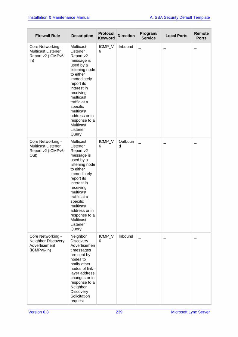
Installation & Maintenance Manual A. SBA Security Default Template
Version 6.8 239 Microsoft Lync Server
Firewall Rule Description Protocol Keyword Direction Program/
Service Local Ports Remote Ports
Core Networking - Multicast Listener Report v2 (ICMPv6-In)
Multicast Listener Report v2 message is used by a listening node to either immediately report its interest in receiving multicast traffic at a specific multicast address or in response to a Multicast Listener Query
ICMP_V6
Inbound _ _ _
Core Networking - Multicast Listener Report v2 (ICMPv6-Out)
Multicast Listener Report v2 message is used by a listening node to either immediately report its interest in receiving multicast traffic at a specific multicast address or in response to a Multicast Listener Query
ICMP_V6
Outbound
_ _ _
Core Networking - Neighbor Discovery Advertisement (ICMPv6-In)
Neighbor Discovery Advertisement messages are sent by nodes to notify other nodes of link-layer address changes or in response to a Neighbor Discovery Solicitation request
ICMP_V6
Inbound _ _ _

Installation & Maintenance Manual 240 Document #: LTRT-39164
Mediant 800B SBA
Firewall Rule Description Protocol Keyword Direction Program/
Service Local Ports Remote Ports
Core Networking - Neighbor Discovery Advertisement (ICMPv6-Out)
Neighbor Discovery Advertisement messages are sent by nodes to notify other nodes of link-layer address changes or in response to a Neighbor Discovery Solicitation request
ICMP_V6
Outbound
_ _ _
Core Networking - Neighbor Discovery Solicitation (ICMPv6-In)
Neighbor Discovery Solicitations are sent by nodes to discover the link-layer address of another on-link IPv6 node
ICMP_V6
Inbound _ _ _
Core Networking - Neighbor Discovery Solicitation (ICMPv6-Out)
Neighbor Discovery Solicitations are sent by nodes to discover the link-layer address of another on-link IPv6 node
ICMP_V6
Outbound
_ _ _
Core Networking - Parameter Problem (ICMPv6-In)
Parameter Problem error messages are sent by nodes as a result of incorrectly generated packets.
ICMP_V6
Inbound _ _ _

Installation & Maintenance Manual A. SBA Security Default Template
Version 6.8 241 Microsoft Lync Server
Firewall Rule Description Protocol Keyword Direction Program/
Service Local Ports Remote Ports
Core Networking - Parameter Problem (ICMPv6-Out)
Parameter Problem error messages are sent by nodes as a result of incorrectly generated packets
ICMP_V6
Outbound
_ _ _
Core Networking - Packet Too Big (ICMPv6-In) Description: . Group: Core Networking Protocol Keyword: ICMP_V6 Direction: Inbound
Packet Too Big error messages are sent from any node that a packet traverses which is unable to forward the packet because the packet is too large for the next link
ICMP_V6
Inbound _ _ _
Core Networking - Packet Too Big (ICMPv6-Out)
Packet Too Big error messages are sent from any node that a packet traverses which is unable to forward the packet because the packet is too large for the next link
ICMP_V6
Outbound
_ _ _
Core Networking - Router Advertisement (ICMPv6-In)
Router Advertisement messages are sent by routers to other nodes for stateless auto-configuration
ICMP_V6
Inbound _ _ _

Installation & Maintenance Manual 242 Document #: LTRT-39164
Mediant 800B SBA
Firewall Rule Description Protocol Keyword Direction Program/
Service Local Ports Remote Ports
Core Networking - Router Advertisement (ICMPv6-Out)
Router Advertisement messages are sent by routers to other nodes for stateless auto-configuration.
ICMP_V6
Outbound
_ _ _
Core Networking - Router Solicitation (ICMPv6-Out)
Router Solicitation messages are sent by nodes seeking routers to provide stateless auto-configuration
ICMP_V6
Outbound
_ _ _
Core Networking - Time Exceeded (ICMPv6-In)
Time Exceeded error messages are generated from any node that a packet traverses if the Hop Limit value is decremented to zero at any point on the path.
ICMP_V6
Inbound _ _ _
Core Networking - Time Exceeded (ICMPv6-Out)
Time Exceeded error messages are generated from any node that a packet traverses if the Hop Limit value is decremented to zero at any point on the path.
ICMP_V6
Outbound
_ _ _

Installation & Maintenance Manual A. SBA Security Default Template
Version 6.8 243 Microsoft Lync Server
Firewall Rule Description Protocol Keyword Direction Program/
Service Local Ports Remote Ports
Core Networking - Internet Group Management Protocol (IGMP-In)
IGMP messages are sent and received by nodes to create, join and depart multicast groups.
IGMP Inbound _ _ _
Core Networking - Internet Group Management Protocol (IGMP-Out)
IGMP messages are sent and received by nodes to create, join and depart multicast groups
IGMP Outbound
_ _ _
Core Networking - IPHTTPS (TCP-In)
Inbound TCP rule to allow IPHTTPS tunneling technology to provide connectivity across HTTP proxies and firewalls.
TCP Inbound _ _ _
Core Networking - IPHTTPS (TCP-Out)
Outbound TCP rule to allow IPHTTPS tunneling technology to provide connectivity across HTTP proxies and firewalls
TCP Outbound
_ _ _
Core Networking - IPv6 (IPv6-In)
Inbound rule required to permit IPv6 traffic for ISATAP (Intra-Site Automatic Tunnel Addressing Protocol) and 6to4 tunneling services.
IPV6 Inbound _ _ _

Installation & Maintenance Manual 244 Document #: LTRT-39164
Mediant 800B SBA
Firewall Rule Description Protocol Keyword Direction Program/
Service Local Ports Remote Ports
Core Networking - IPv6 (IPv6-Out)
Outbound rule required to permit IPv6 traffic for ISATAP (Intra-Site Automatic Tunnel Addressing Protocol) and 6to4 tunneling services
IPV6 Outbound
_ _ _
Core Networking - Teredo (UDP-In)
Inbound UDP rule to allow Teredo edge traversal, a technology that provides address assignment and automatic tunneling for unicast IPv6 traffic when an IPv6/IPv4 host is located behind an IPv4 network address translator.
UDP Inbound _ _ _
Core Networking - Teredo (UDP-Out)
Outbound UDP rule to allow Teredo edge traversal, a technology that provides address assignment and automatic tunneling for unicast IPv6 traffic when an IPv6/IPv4 host is located behind an IPv4 network address translator
UDP Outbound
_ _ _

Installation & Maintenance Manual A. SBA Security Default Template
Version 6.8 245 Microsoft Lync Server
Firewall Rule Description Protocol Keyword Direction Program/
Service Local Ports Remote Ports
File and Printer Sharing (Echo Request - ICMPv4-In)
Echo Request messages are sent as ping requests to other nodes
ICMP_V4
Inbound _ _ _
File and Printer Sharing (Echo Request - ICMPv4-Out)
Echo Request messages are sent as ping requests to other nodes. Group: File and Printer Sharing
ICMP_V4
Outbound
_ _ _
File and Printer Sharing (Echo Request - ICMPv6-In)
Echo Request messages are sent as ping requests to other nodes
ICMP_V6
Inbound _ _ _
File and Printer Sharing (Echo Request - ICMPv6-Out)
Echo Request messages are sent as ping requests to other nodes
ICMP_V6
Outbound
_ _ _
File and Printer Sharing (NB-Datagram-In)
Inbound rule for File and Printer Sharing to allow NetBIOS Datagram transmission and reception. [UDP 138]
UDP Inbound _ 138 _

Installation & Maintenance Manual 246 Document #: LTRT-39164
Mediant 800B SBA
Firewall Rule Description Protocol Keyword Direction Program/
Service Local Ports Remote Ports
File and Printer Sharing (NB-Datagram-Out)
Outbound rule for File and Printer Sharing to allow NetBIOS Datagram transmission and reception. [UDP 138]
UDP Outbound
_ _ 138
File and Printer Sharing (NB-Name-In)
Inbound rule for File and Printer Sharing to allow NetBIOS Name Resolution. [UDP 137]
UDP Inbound _ 137 _
File and Printer Sharing (NB-Session-In)
Inbound rule for File and Printer Sharing to allow NetBIOS Session Service connections. [TCP 139]
TCP Inbound _ 139 _
File and Printer Sharing (NB-Session-Out)
Outbound rule for File and Printer Sharing to allow NetBIOS Session Service connections. [TCP 139]
TCP Outbound
_ _ 139
File and Printer Sharing (Spooler Service - RPC-EPMAP)
Inbound rule for the RPCSS service to allow RPC/TCP traffic for the Spooler Service.
TCP Inbund rpcss RPCEndPointMapper
_

Installation & Maintenance Manual A. SBA Security Default Template
Version 6.8 247 Microsoft Lync Server
Firewall Rule Description Protocol Keyword Direction Program/
Service Local Ports Remote Ports
File and Printer Sharing (SMB-In)
Inbound rule for File and Printer Sharing to allow Server Message Block transmission and reception via Named Pipes. [TCP 445]
TCP Inbound _ 445 _
File and Printer Sharing (SMB-Out)
Outbound rule for File and Printer Sharing to allow Server Message Block transmission and reception via Named Pipes. [TCP 445]
TCP Outbound
_ _ 445
World Wide Web Services (HTTP Traffic-In)
An inbound rule to allow HTTP traffic for Internet Information Services (IIS) [TCP 80]
TCP Inbound _ 80 _
World Wide Web Services (HTTPS Traffic-In)
An inbound rule to allow HTTPS traffic for Internet Information Services (IIS) [TCP 443]
TCP Inbound _ 443 _
Message Queuing Message Queuing
TCP Inbound mqsvc.exe _ _
Message Queuing Description: Group: Message Queuing Protocol Keyword: UDP Direction: Inbound
Message Queuing
UDP Inbound mqsvc.exe _ _
Message Queuing Message Queuing
TCP Outbound
Mqsvc.exe _ _

Installation & Maintenance Manual 248 Document #: LTRT-39164
Mediant 800B SBA
Firewall Rule Description Protocol Keyword Direction Program/
Service Local Ports Remote Ports
Message Queuing Message Queuing
UDP Outbound
Mqsvc.exe _ _
Message Queuing Message Queuing
PGM Inbound _ _ _
Message Queuing Message Queuing
PGM Outbound
_ _ _
Netlogon Service (NP-In)
Inbound rule for the NetLogon service to be remotely managed over Named Pipes
TCP Inbound _ 445 _
Remote Administration (RPC)
Inbound rule for all services to be remotely managed via RPC/TCP
TCP Inbound _ DynamicRPC _
Remote Administration (NP-In)
Inbound rule for all services to be remotely managed over Named Pipes
TCP Inbound _ 445 _
Remote Administration (RPC-EPMAP) Description: .
Inbound rule for the RPCSS service to allow RPC/TCP traffic for all the local services
TCP Inbound rpcss RPCEndPointMapper
_
Remote Desktop (TCP-In)
Inbound rule for the Remote Desktop service to allow RDP traffic. [TCP 3389]
TCP Inbound _ 3389 _

Installation & Maintenance Manual A. SBA Security Default Template
Version 6.8 249 Microsoft Lync Server
Firewall Rule Description Protocol Keyword Direction Program/
Service Local Ports Remote Ports
Remote Event Log Management (RPC)
Inbound rule for the local Event Log service to be remotely managed via RPC/TCP.
TCP Inbound _ DynamicRPC _
Remote Event Log Management (NP-In)
Inbound rule for the local Event Log service to be remotely managed over Named Pipes
TCP Inbound _ 445 _
Remote Event Log Management (RPC-EPMAP)
Inbound rule for the RPCSS service to allow RPC/TCP traffic for the local Event Log Service.
TCP Inbound Rpcss RPCEndPointMapper
_
Windows Firewall Remote Management (RPC)
Inbound rule for the Windows Firewall to be remotely managed via RPC/TCP
TCP Inbound policyagent DynamicRPC _
Windows Firewall Remote Management (RPC-EPMAP)
Inbound rule for the RPCSS service to allow RPC/TCP traffic for the Windows Firewall
TCP Inbound rpcss RPCEndPointMapper
_
SCW remote access firewall rule - Scshost - Dynamic RPC
Allow inbound access for scshost using dynamic RPC and protocol TCP
TCP Inbound scshost DynamicRPC _

Installation & Maintenance Manual 250 Document #: LTRT-39164
Mediant 800B SBA
Firewall Rule Description Protocol Keyword Direction Program/
Service Local Ports Remote Ports
SCW remote access firewall rule - Scshost - End Point RPC Mapper
Allow inbound access for scshost using end point RPC mapper and protocol TCP
TCP Inbound scshost RPCEndPointMapper
_
SCW remote access firewall rule - Svchost - TCP
Allow inbound access for svchost using port 135 and protocol TCP
TCP Inbound svschost 135 _
SCW inbound access firewall rule - System - TCP
Allow inbound access for system using ports 139, 445 and protocol TCP
TCP Inbound _ 139, 445 _
SCW remote access firewall rule - System - UDP
Allow inbound access for system using port 137 and protocol UDP
UDP Inbound _ 137 _
SNMP Service (UDP In)
Inbound rule for the Simple Network Management Protocol (SNMP) Service to allow SNMP traffic. [UDP 161]
UDP Inbound snmp 161 _
SNMP Trap Service (UDP In)
Inbound rule for the SNMP Trap Service to allow SNMP traps. [UDP 162]
UDP Inbound snmptrap 162 LocalSubnet
SNMP Trap Service (UDP In)
Inbound rule for the SNMP Trap Service to allow SNMP traps. [UDP 162]
UDP Inbound snmptrap 162 _
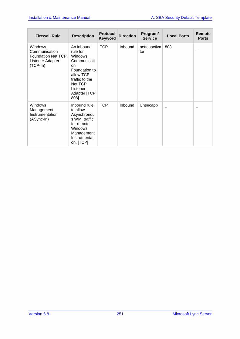
Installation & Maintenance Manual A. SBA Security Default Template
Version 6.8 251 Microsoft Lync Server
Firewall Rule Description Protocol Keyword Direction Program/
Service Local Ports Remote Ports
Windows Communication Foundation Net.TCP Listener Adapter (TCP-In)
An inbound rule for Windows Communication Foundation to allow TCP traffic to the Net.TCP Listener Adapter [TCP 808]
TCP Inbound nettcpactivator
808 _
Windows Management Instrumentation (ASync-In)
Inbound rule to allow Asynchronous WMI traffic for remote Windows Management Instrumentation. [TCP]
TCP Inbound Unsecapp _ _

Installation & Maintenance Manual 252 Document #: LTRT-39164
Mediant 800B SBA
A.6.2 SBA Network Firewall Settings The table below describes the various network firewall settings that are required for connections between the different components in the SBA network.
Table A-6: SBA Network Firewall Setting
Source Destination Destination port Transport Protocol Notes
CMS SBA 445 TCP SMB Central Management Server Replication
Front End Servers SBA 5061 TCP SIP/MTLS SIP Signalling
Front End Servers SBA 444 TCP HTTPS Certificate replication
Front End Servers SBA 50001 TCP SIP/MTLS Centralized Logging
Service
Front End Servers SBA 50002 TCP SIP/MTLS Centralized Logging
Service
Front End Servers SBA 50003 TCP SIP/MTLS Centralized Logging
Service
Front End Servers SBA 5090 TCP SIP/MTLS WinFabFederationPort
Front End Servers SBA 5091 TCP SIP/MTLS WinFabLeaseAgentPort
Front End Servers SBA 5092 TCP SIP/MTLS WinFabClientConnectionP
ort
Front End Servers SBA 5093 TCP SIP/MTLS WinFabIPCPort
Front End Servers SBA 5094 TCP SIP/MTLS WinFabReplicationPort
SBA Front End Servers 444 TCP HTTPS Certificate replication
SBA Front End Servers 5061 TCP SIP/MTLS SIP signalling
SBA Front End Servers 5088 TCP SIP/MTLS Lync 2013 mobility -
UCWA
SBA Front End Servers 5089 TCP SIP/MTLS Lync 2013 mobility-UCWA
SBA Front End Servers 50001 TCP SIP/MTLS Centralized Logging
Service
SBA Front End Servers 50002 TCP SIP/MTLS Centralized Logging
Service
SBA Front End Servers 50003 TCP SIP/MTLS Centralized Logging
Service

Installation & Maintenance Manual A. SBA Security Default Template
Version 6.8 253 Microsoft Lync Server
Source Destination Destination port Transport Protocol Notes
SBA Front End Servers 5090 TCP SIP/MTLS WinFabFederationPort
SBA Front End Servers 5091 TCP SIP/MTLS WinFabLeaseAgentPort
SBA Front End Servers 5092 TCP SIP/MTLS WinFabClientConnectionP
ort
SBA Front End Servers 5093 TCP SIP/MTLS WinFabIPCPort
SBA Front End Servers 5094 TCP SIP/MTLS WinFabReplicationPort
SBA Director 444 TCP HTTPS Certificate replication
SBA Edge Pool 5062 TCP SIP/MTLS SIP connection for requesting MRAS credentials
SBA Edge Pool 443 TCP SRTP Audio Ports to external
SBA Edge Pool 3478 UDP SRTP Audio Ports to external
Mediation Pool
Media Gateway 5067 TCP SIP/MTLS SIP Signalling
Mediation Pool
Media Gateway 5068 TCP SIP SIP Signalling

Installation & Maintenance Manual 254 Document #: LTRT-39164
Mediant 800B SBA
This page is intentionally left blank.

Installation & Maintenance Manual B. Running Anti-Virus Software
Version 6.8 255 Microsoft Lync Server
B Running Anti-Virus Software When Anti-Virus software is run on SBA components, ensure that the Antivirus file scanning exclusions are based on the following Microsoft recommendations: SBA 2010: https://technet.microsoft.com/en-us/library/gg195736.aspx SBA 2013: https://technet.microsoft.com/en-
us/library/dn440138%28v=ocs.15%29.aspx

SBA Installation and Maintenance Manual
www.audiocodes.com www.audiocodes.com