saz3b microprocessor and its applications … · n negative/ sign flag indicates that the result of...
TRANSCRIPT
SAZ3B
MICROPROCESSOR AND
ITS APPLICATIONS
Unit : I -V
TM
SAZ3B –MICROPROCESSORS AND ITS APPLICATIONS 2
2
UNIT-I
Introduction to Micro Computers.
Microprocessor and assembly language
Microprocessor Architecture and its Operations.
8085 MPU
8085 Instruction set and Classifications

TM
SAZ3B –MICROPROCESSORS AND ITS APPLICATIONS 3
BLOCK DIAGRAM OF A BASIC
COMPUTER SYSTEM
ROM RAM I/O
interface
I/O
devices
CPU
3
Basic computer system consist of a Central processing unit (CPU),
memory (RAM and ROM), input/output (I/O) unit.
Block diagram of a basic computer system
Address bus
Data bus Control
bus
TM
SAZ3B –MICROPROCESSORS AND ITS APPLICATIONS 4
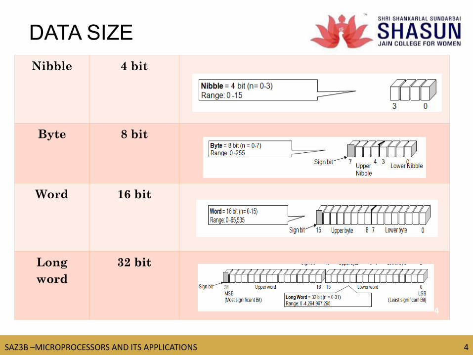
DATA SIZE
Nibble 4 bit
Byte 8 bit
Word 16 bit
Long
word
32 bit
4

TM
SAZ3B –MICROPROCESSORS AND ITS APPLICATIONS 5
https://www.youtube.com/watch?v=yYukhcwX7jc
MICROPROCESSOR
•Microprocessor and Microcontroller consists of the following
functional units

TM
SAZ3B –MICROPROCESSORS AND ITS APPLICATIONS 6
Microprocessor based Bus
Architecture
•8085 is pronounced as "eighty-eighty-five" microprocessor. It is an 8-bit
microprocessor designed by Intel in 1977 using NMOS technology.

TM
SAZ3B –MICROPROCESSORS AND ITS APPLICATIONS 7
INTERNAL STRUCTURE AND
BASIC OPERATION OF
MICROPROCESSOR
ALU
Register
Section
Control and timing section
Address bus
Data bus
Control bus
7 Block diagram of a microprocessor
TM
SAZ3B –MICROPROCESSORS AND ITS APPLICATIONS 8
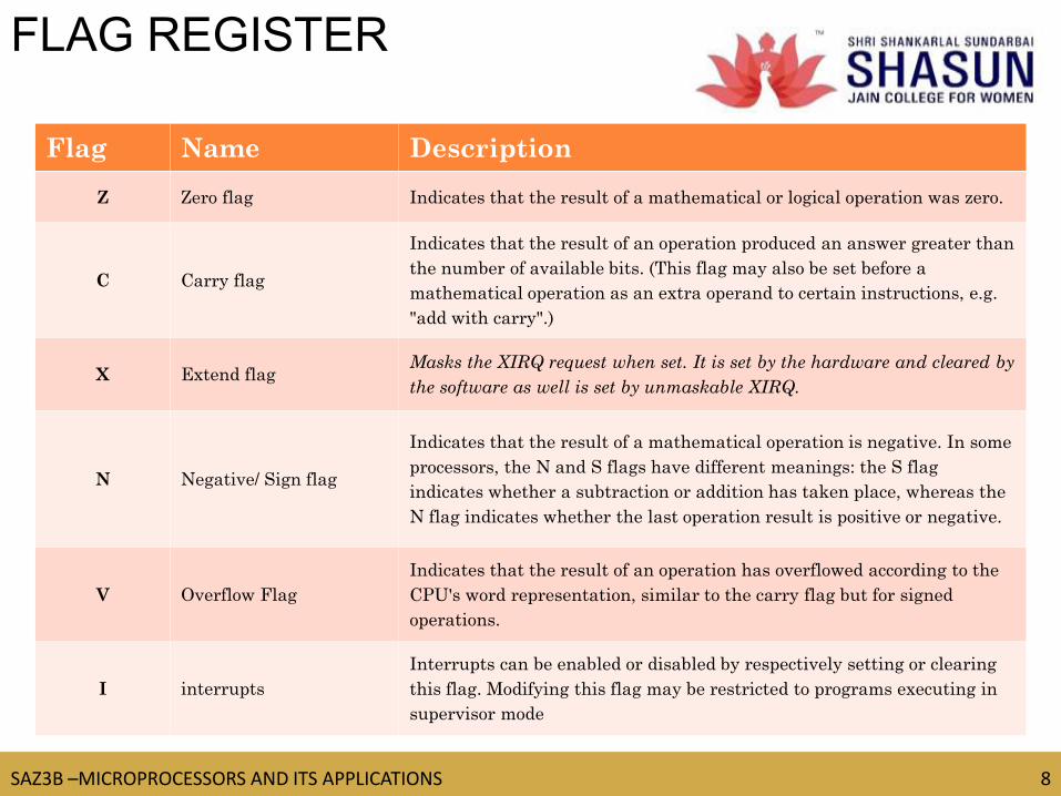
Flag Name Description
Z Zero flag Indicates that the result of a mathematical or logical operation was zero.
C Carry flag
Indicates that the result of an operation produced an answer greater than
the number of available bits. (This flag may also be set before a
mathematical operation as an extra operand to certain instructions, e.g.
"add with carry".)
X Extend flag Masks the XIRQ request when set. It is set by the hardware and cleared by
the software as well is set by unmaskable XIRQ.
N Negative/ Sign flag
Indicates that the result of a mathematical operation is negative. In some
processors, the N and S flags have different meanings: the S flag
indicates whether a subtraction or addition has taken place, whereas the
N flag indicates whether the last operation result is positive or negative.
V Overflow Flag
Indicates that the result of an operation has overflowed according to the
CPU's word representation, similar to the carry flag but for signed
operations.
I interrupts
Interrupts can be enabled or disabled by respectively setting or clearing
this flag. Modifying this flag may be restricted to programs executing in
supervisor mode
FLAG REGISTER

TM
SAZ3B –MICROPROCESSORS AND ITS APPLICATIONS 9
a 16 bit register, used to store the next address of the operation code to be fetched by the CPU.
Not much use in programming, but as an indicator to user only.
Purpose of PC in a Microprocessor
to store address of tos (top of stack)
to store address of next instruction to be executed.
count the number of instructions.
to store base address of the stack.
PROGRAM COUNTER
TM
SAZ3B –MICROPROCESSORS AND ITS APPLICATIONS 10
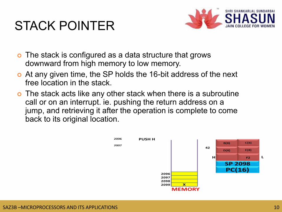
The stack is configured as a data structure that grows downward from high memory to low memory.
At any given time, the SP holds the 16-bit address of the next free location in the stack.
The stack acts like any other stack when there is a subroutine call or on an interrupt. ie. pushing the return address on a jump, and retrieving it after the operation is complete to come back to its original location.
STACK POINTER

TM
SAZ3B –MICROPROCESSORS AND ITS APPLICATIONS 11
PIN DIAGRAM
The following image shows the pin diagram of 8085 Microprocessor

TM
SAZ3B –MICROPROCESSORS AND ITS APPLICATIONS 12
8085 ARCHITECTURE
The following image shows the architecture diagram of 8085
Microprocessor

TM
SAZ3B –MICROPROCESSORS AND ITS APPLICATIONS 13
https://www.youtube.com/watch?v=p4RcMLFIr5o
COMPONENTS OF MP
8085 consists of the following functional units
TM
SAZ3B –MICROPROCESSORS AND ITS APPLICATIONS 1 4
8085 INSTRUCTION SET
https://www.youtube.com/watch?v=fNYglxdl0lw
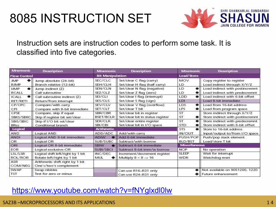
Instruction sets are instruction codes to perform some task. It is
classified into five categories.
TM
SAZ3B –MICROPROCESSORS AND ITS APPLICATIONS 1 5
ASSEMBLY LANGUAGE
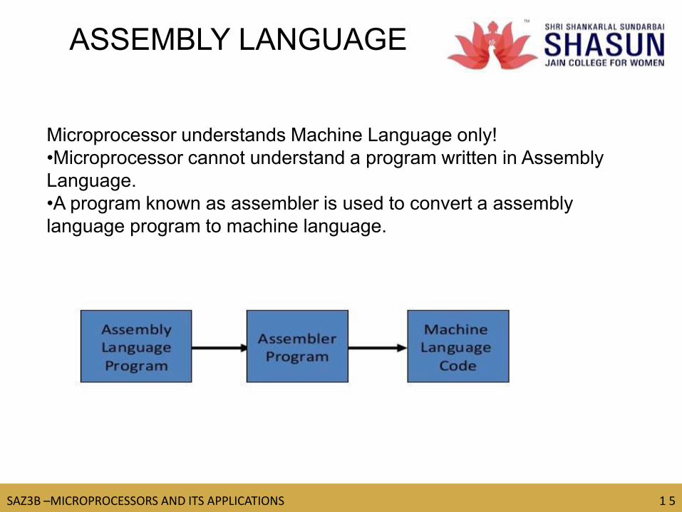
Microprocessor understands Machine Language only!
•Microprocessor cannot understand a program written in Assembly
Language.
•A program known as assembler is used to convert a assembly
language program to machine language.

TM
SAZ3B –MICROPROCESSORS AND ITS APPLICATIONS 16
16
UNIT-II
Writing Assembly level programs.
Programming techniques such as looping, counting and
indexing
Addressing Modes
Data Transfer Instructions
Arithmetic and Logic Operations
Dynamic Debugging

TM
SAZ3B –MICROPROCESSORS AND ITS APPLICATIONS 17
17
ASSEMBLY LEVEL
PROGRAMS
An assembly language, often abbreviated asm, is a low-level programming
language for a computer, or other programmable device, in which there is a
very strong correspondence between the language and the architecture's
machine code instructions.
TM
SAZ3B –MICROPROCESSORS AND ITS APPLICATIONS 1 8
18
LOOPING,COUNTING AND
INDEXING
Looping-In this technique, the program is instructed to
execute certain set of instructions repeatedly to execute a
particular task number of times.
Counting-This technique allows programmer to count how
many times the instruction/set of instructions are executed.
Indexing-This technique allows programmer to point or refer
the data stored in sequential memory location one by one.

TM
SAZ3B –MICROPROCESSORS AND ITS APPLICATIONS 1 9
19
1. Counter is set up by loading an appropriate count in a register.
2. Counting is performed by either incrementing or decrementing the
counter.
3. Loop is set up by a conditional Jump instruction.
4. End of counting is indicated by a flag.
Note: It is easy to count down than count up.
HOW THE COUNTER
WORKS?
https://www.youtube.com/watch?v=1d9sSoYYjcA
TM
SAZ3B –MICROPROCESSORS AND ITS APPLICATIONS 20
20
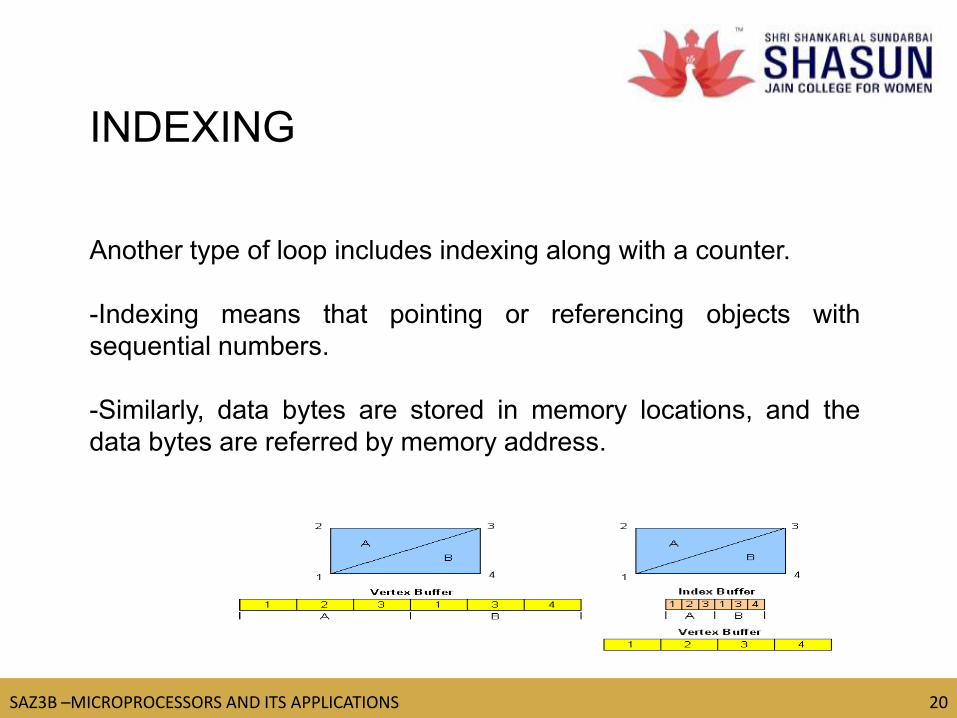
Another type of loop includes indexing along with a counter.
-Indexing means that pointing or referencing objects with
sequential numbers.
-Similarly, data bytes are stored in memory locations, and the
data bytes are referred by memory address.
INDEXING
TM
SAZ3B –MICROPROCESSORS AND ITS APPLICATIONS 21
21
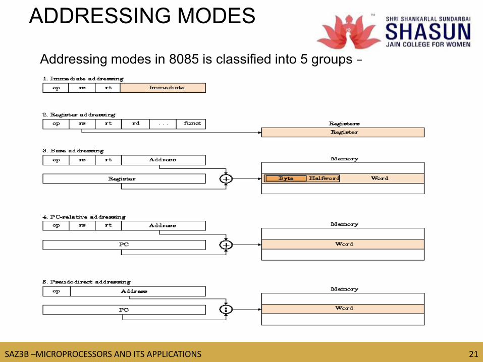
ADDRESSING MODES
Addressing modes in 8085 is classified into 5 groups −

TM
SAZ3B –MICROPROCESSORS AND ITS APPLICATIONS 22
22
SUMMARY OF ADDRESSING
MODES

TM
SAZ3B –MICROPROCESSORS AND ITS APPLICATIONS 23
23
DATA TRANSFER
INSTRUCTIONS
LHLD
16-bit address
Load H and L registers direct The instruction copies the contents of the memory location pointed out by the
address into register L and copies the contents of the next memory location
into register H.
Example − LHLD 3225K
TM
SAZ3B –MICROPROCESSORS AND ITS APPLICATIONS 24
24
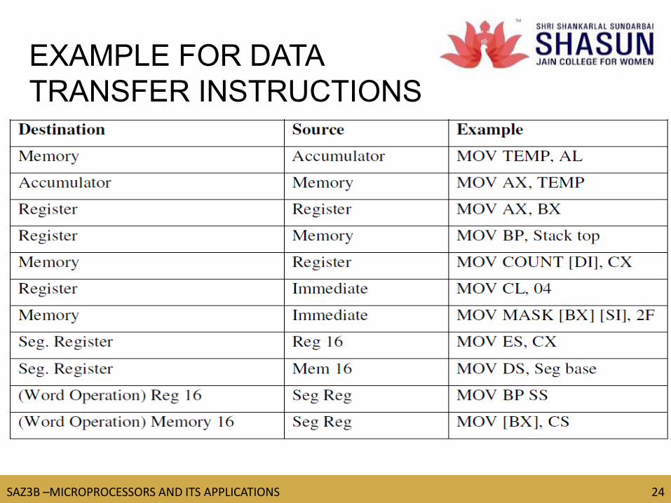
EXAMPLE FOR DATA
TRANSFER INSTRUCTIONS

TM
SAZ3B –MICROPROCESSORS AND ITS APPLICATIONS 25
25
DATA TRANSFER
INSTRUCTIONS
TM
SAZ3B –MICROPROCESSORS AND ITS APPLICATIONS 26
26
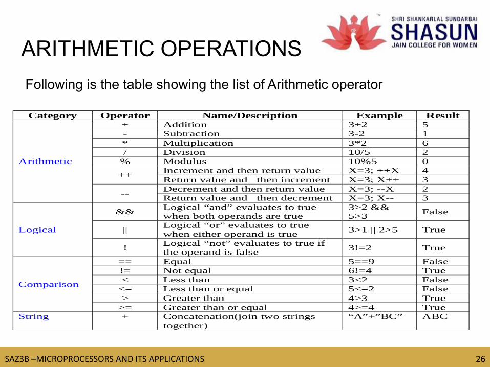
ARITHMETIC OPERATIONS
Following is the table showing the list of Arithmetic operator
TM
SAZ3B –MICROPROCESSORS AND ITS APPLICATIONS 27
27
The 8085 microprocessor performs various arithmetic operations,
such as addition, subtraction, increment, and decrement.
1.ADD
2.ADI
3.SUB
4.SUI
5.INR
6.DCR
ARITHMETIC OPERATIONS
https://www.youtube.com/watch?v=_x82o2YVz9Y
TM
SAZ3B –MICROPROCESSORS AND ITS APPLICATIONS 28
28
LOGICAL INSTRUCTIONS
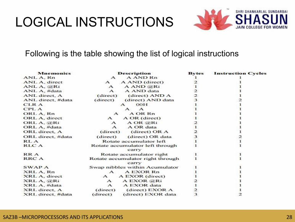
Following is the table showing the list of logical instructions
TM
SAZ3B –MICROPROCESSORS AND ITS APPLICATIONS 29
29
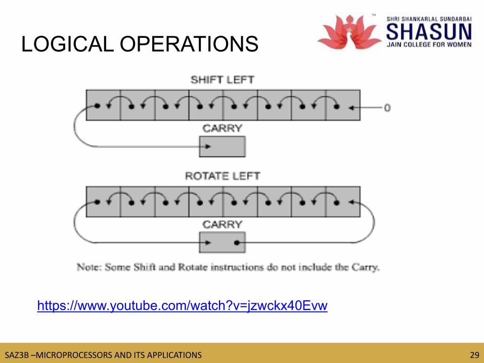
LOGICAL OPERATIONS
https://www.youtube.com/watch?v=jzwckx40Evw
TM
SAZ3B –MICROPROCESSORS AND ITS APPLICATIONS 30
30
-Similar to Troubleshooting hardware.
-It is essential to search carefully for the errors in the
- Program logic,
- Machine codes and
- Execution.
The debugging process can be divided into
-Static Debugging.
-Dynamic Debugging.
DYNAMIC DEBUGGING
https://www.youtube.com/watch?v=P3QfxQHjpgo
TM
SAZ3B –MICROPROCESSORS AND ITS APPLICATIONS 31
31
UNIT-III
Counters and time Delays
HexaDecimal Counter
Modulo 10 Counter
Pulse Timings for Flashing lights
Debugging Counter and Time delay program
Stack
Subroutine
Conditional call and return instructions
TM
SAZ3B –MICROPROCESSORS AND ITS APPLICATIONS 32
32
•A loop counter is set up by loading a register with a certain value
•Then using the DCR (to decrement) and INR (to increment) the contents of
the register are updated.
•A loop is set up with a conditional jump instruction that loops back or not
depending on whether the count has reached the termination count.
COUNTERS
Knowing how many T-States an instruction requires, and keeping in
mind that a T-State is one clock cycle long, we can calculate the
time using the following formula:
Delay = No. of T-States / Frequency
TIME DELAYS
TM
SAZ3B –MICROPROCESSORS AND ITS APPLICATIONS 33
33
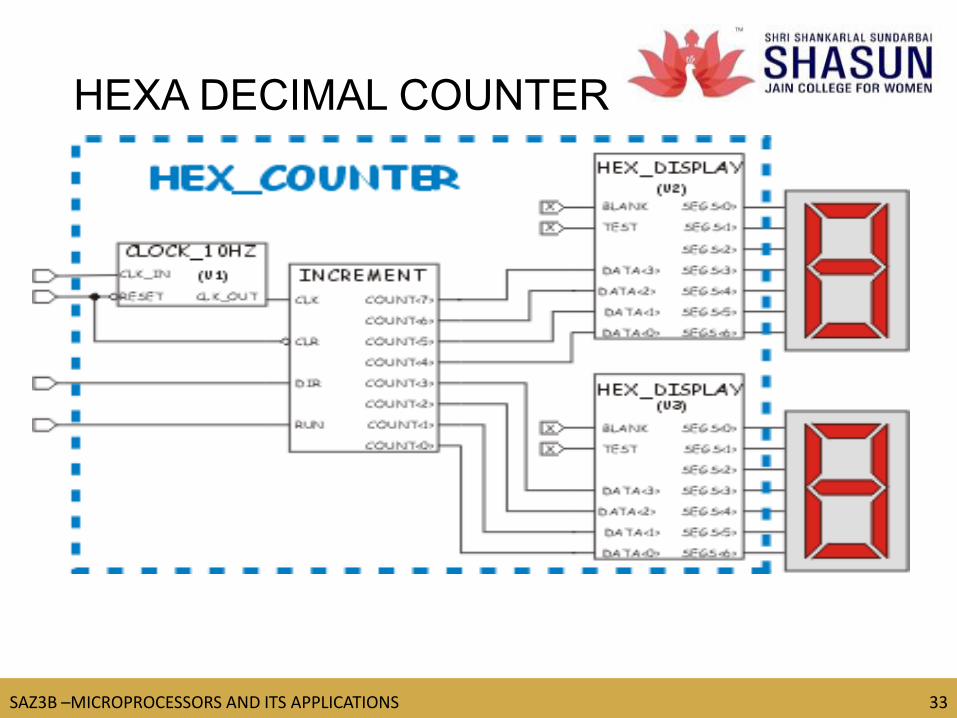
HEXA DECIMAL COUNTER

TM
SAZ3B –MICROPROCESSORS AND ITS APPLICATIONS 34
34
Initialize B as a Counter
Decrement Counter
Load Register C with Delay
Count
Decrement Delay Count
Is Delay
Count =0?
Display Output
Go To Next Count
No
Yes
FLOW CHART OF HEXA
DECIMAL COUNTER

TM
SAZ3B –MICROPROCESSORS AND ITS APPLICATIONS 35
35
•A program to count from 0 to 9 with a one-second delay
between each count.
•At the count of 9, the counter should reset itself to 0 and
repeat the sequence continuously.
•Use register pair HL to set up the delay, and display each
count at one of the output ports.
•Assume the clock frequency of the microcomputer is 1 MHz
MODULO 10 COUNTER
TM
SAZ3B –MICROPROCESSORS AND ITS APPLICATIONS 36
36
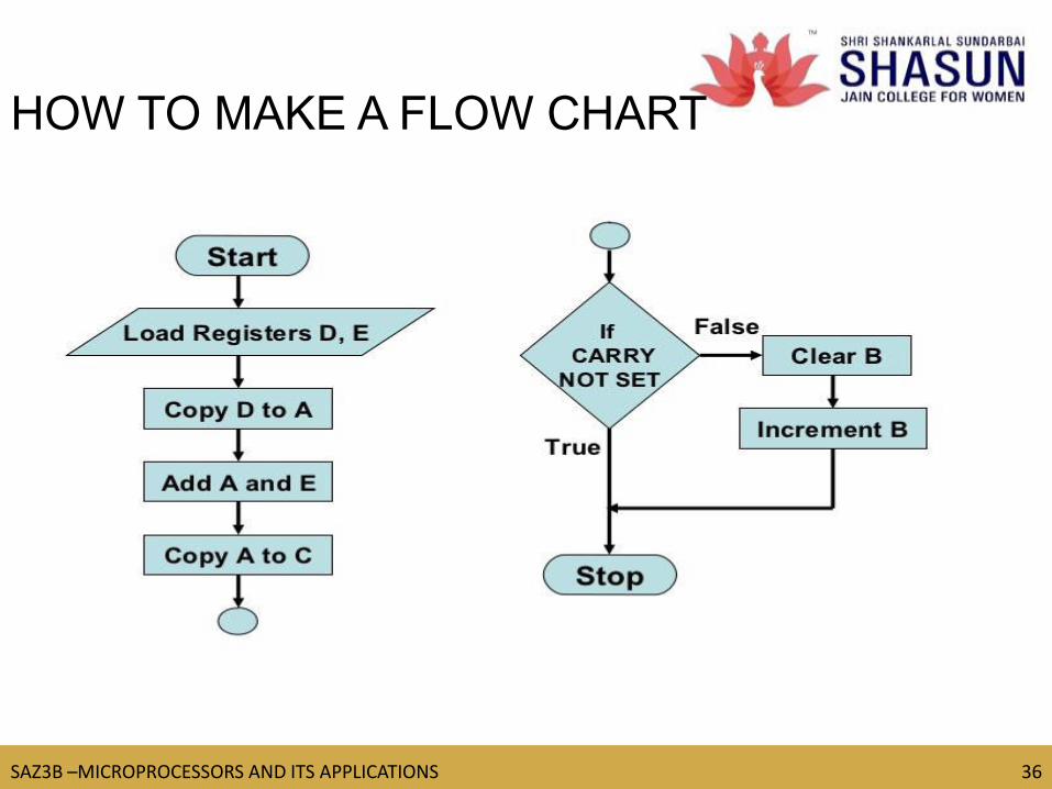
HOW TO MAKE A FLOW CHART

TM
SAZ3B –MICROPROCESSORS AND ITS APPLICATIONS 37
37
PULSE TIMINGS FOR
FLASHING LIGHTS
TM
SAZ3B –MICROPROCESSORS AND ITS APPLICATIONS 38
38
The debugging techniques can be used to check errors in counter program.
Errors in counting T-States in a delay loop. (Load delay register is
mistakenly included in the loop)
Error in recognizing how many times a loop is repeated.
DEBUGGING COUNTER

TM
SAZ3B –MICROPROCESSORS AND ITS APPLICATIONS 39
39
STACK
https://www.youtube.com/watch?v=UjZwIl2Nrp
stack pointer is a small register that stores the address of the
last program request in a stack. Astack is a specialized buffer
which stores data from the top down
TM
SAZ3B –MICROPROCESSORS AND ITS APPLICATIONS 40
40
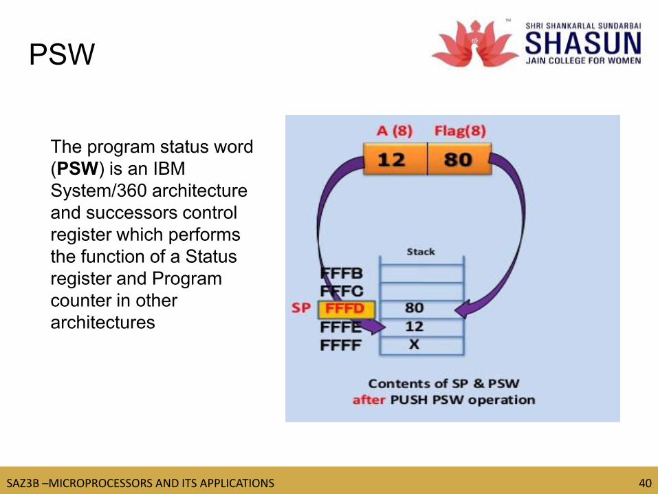
The program status word
(PSW) is an IBM
System/360 architecture
and successors control
register which performs
the function of a Status
register and Program
counter in other
architectures
PSW
TM
SAZ3B –MICROPROCESSORS AND ITS APPLICATIONS 41
41
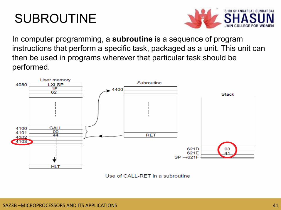
SUBROUTINE
In computer programming, a subroutine is a sequence of program
instructions that perform a specific task, packaged as a unit. This unit can
then be used in programs wherever that particular task should be
performed.
TM
SAZ3B –MICROPROCESSORS AND ITS APPLICATIONS 42
42
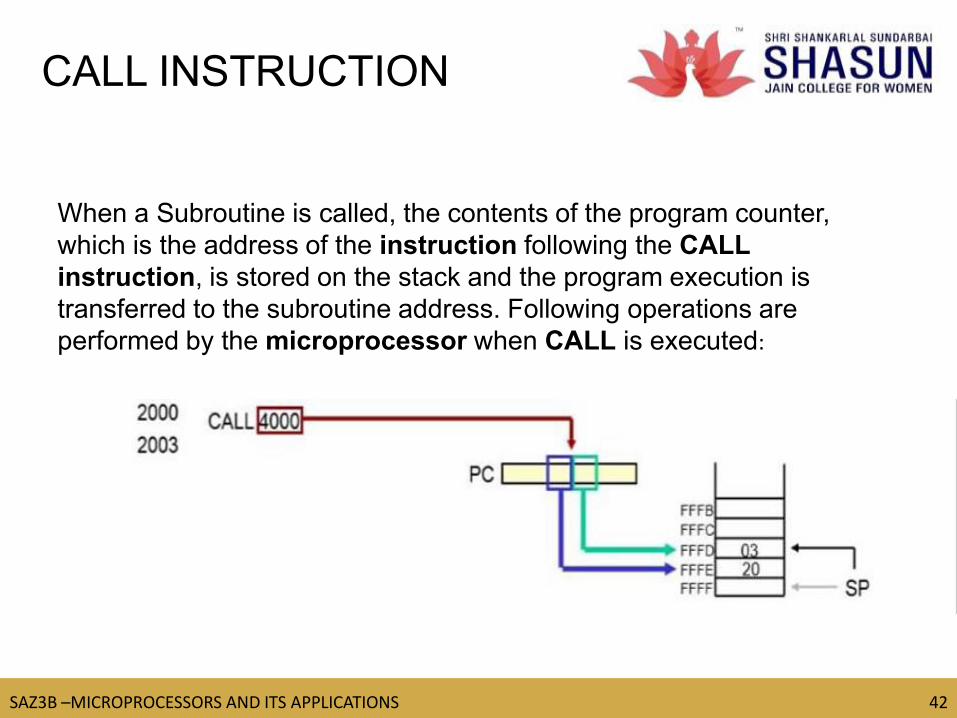
When a Subroutine is called, the contents of the program counter,
which is the address of the instruction following the CALL
instruction, is stored on the stack and the program execution is
transferred to the subroutine address. Following operations are
performed by the microprocessor when CALL is executed:
CALL INSTRUCTION

TM
SAZ3B –MICROPROCESSORS AND ITS APPLICATIONS 43
43 https://www.youtube.com/watch?v=GfI__0DvbHo
RET (1 byte instruction)
–
Retrieve the return address from the top of the
stack
–
Load the program counter with the return
address.
RETURN AND RESTART
INSTRUCTIONS
TM
SAZ3B –MICROPROCESSORS AND ITS APPLICATIONS 44
44
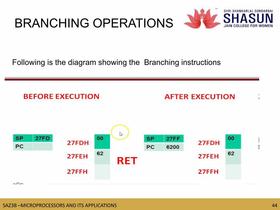
BRANCHING OPERATIONS
Following is the diagram showing the Branching instructions

TM
SAZ3B –MICROPROCESSORS AND ITS APPLICATIONS 45
45
RETURN INSTRUCTIONS
RET (1 byte instruction)
Retrieve the return address from the top of the
stack

TM
SAZ3B –MICROPROCESSORS AND ITS APPLICATIONS 46
46
UNIT-IV
BCD to Binary and Vice Versa
BCD to Hex and Vice Versa
BCD conversions
ASCII to BCD and Vice Versa
BCD to seven segment LED code conversions
Binary to ASCII and Vice Versa
BCD Addition
BCD Subtraction
BCD Multiplication
BCD Division

TM
SAZ3B –MICROPROCESSORS AND ITS APPLICATIONS 47
47
BCD TO BINARY
TM
SAZ3B –MICROPROCESSORS AND ITS APPLICATIONS 48
48
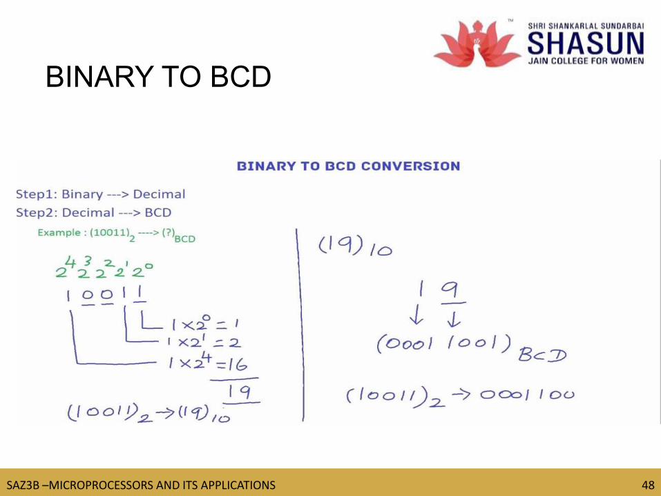
BINARY TO BCD
TM
SAZ3B –MICROPROCESSORS AND ITS APPLICATIONS 49
49
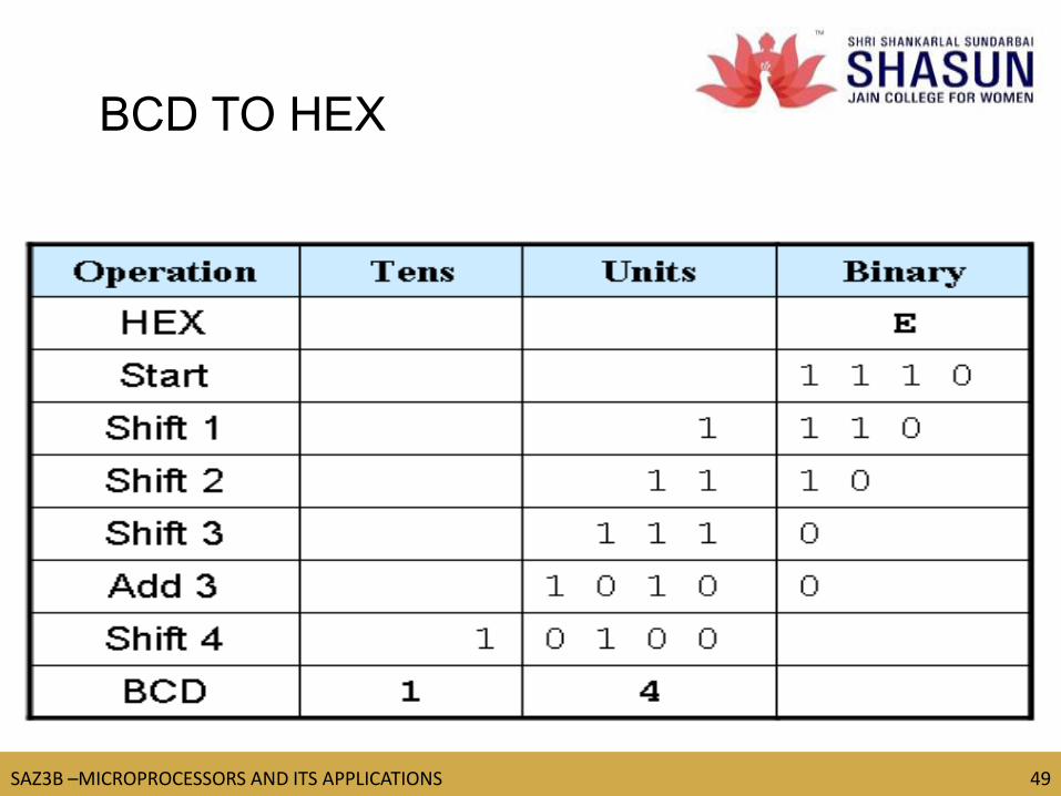
BCD TO HEX
TM
SAZ3B –MICROPROCESSORS AND ITS APPLICATIONS 50
50
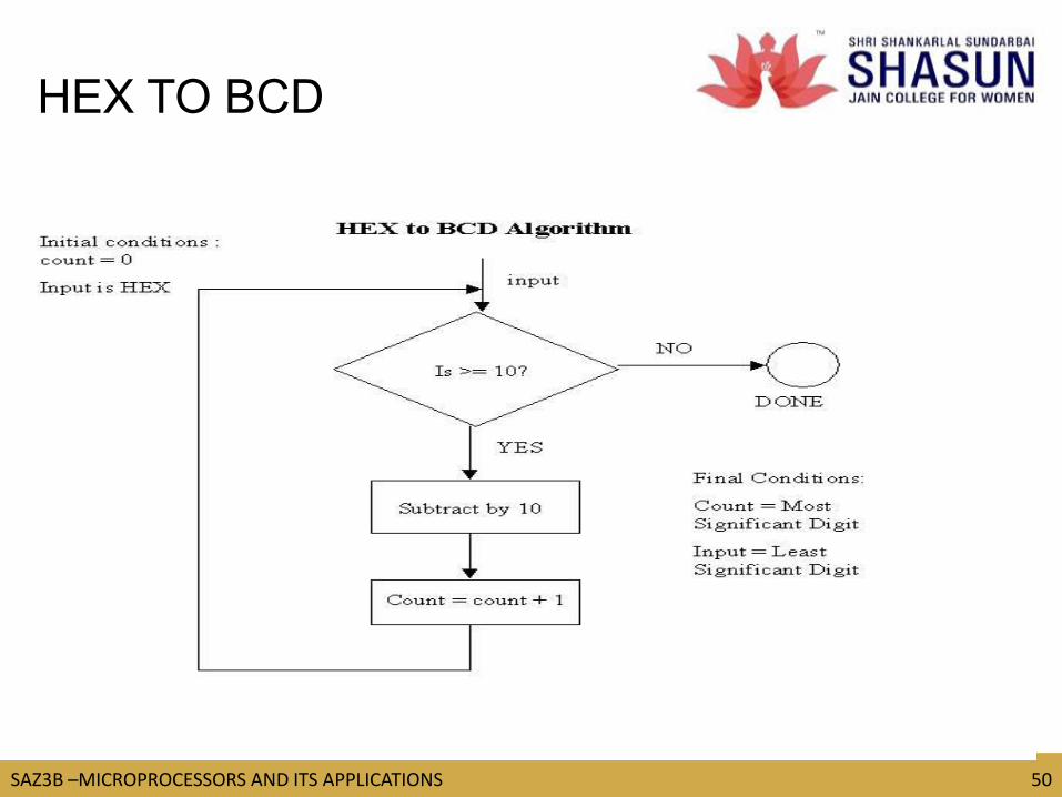
HEX TO BCD

TM
SAZ3B –MICROPROCESSORS AND ITS APPLICATIONS 51
51
ASCII TO BCD
https://www.youtube.com/watch?v=URtoaTlgFs8
TM
SAZ3B –MICROPROCESSORS AND ITS APPLICATIONS 52
52
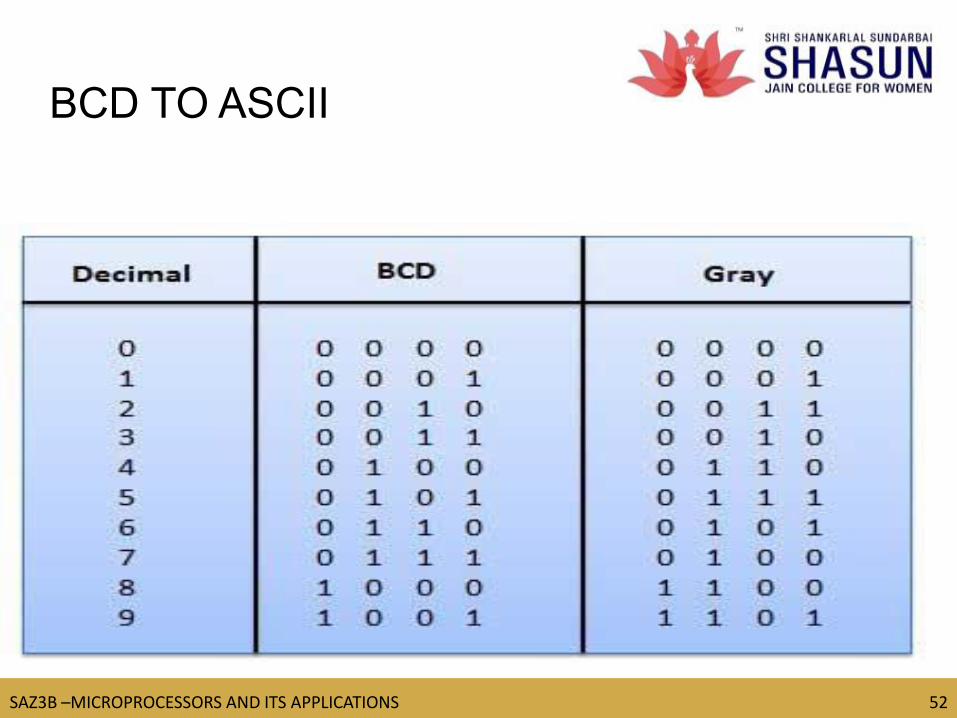
BCD TO ASCII
TM
SAZ3B –MICROPROCESSORS AND ITS APPLICATIONS 53
53
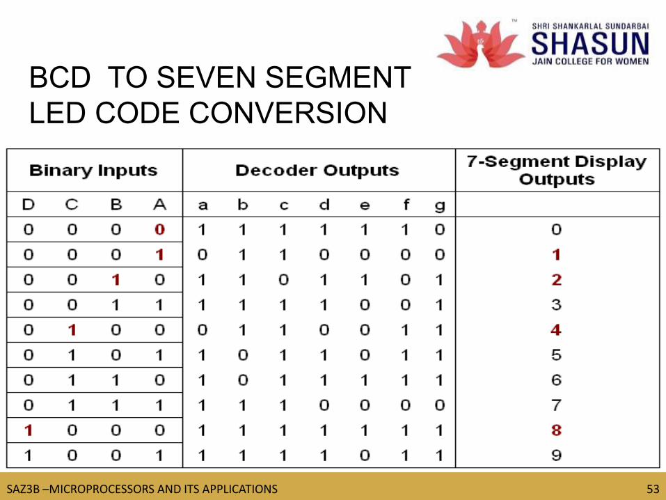
BCD TO SEVEN SEGMENT
LED CODE CONVERSION

TM
SAZ3B –MICROPROCESSORS AND ITS APPLICATIONS 54
54
BINARY TO ASCII
TM
SAZ3B –MICROPROCESSORS AND ITS APPLICATIONS 55
55
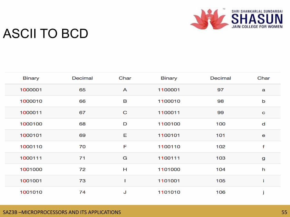
ASCII TO BCD
TM
SAZ3B –MICROPROCESSORS AND ITS APPLICATIONS 56
56
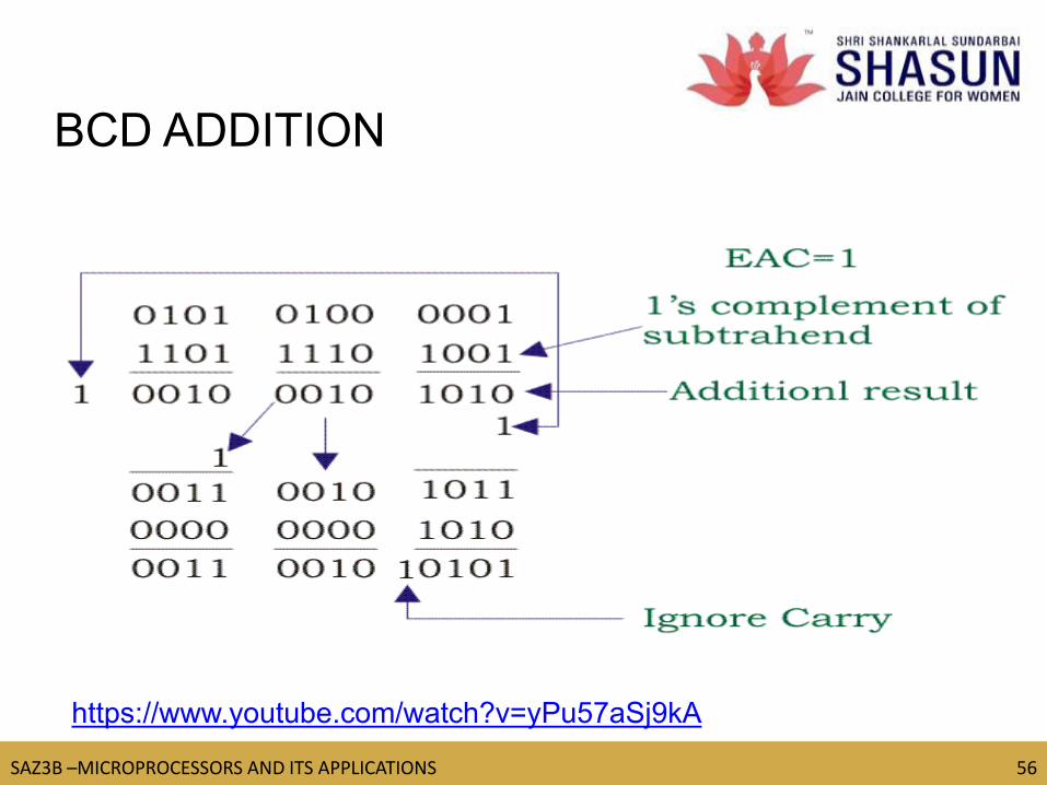
BCD ADDITION
https://www.youtube.com/watch?v=yPu57aSj9kA
TM
SAZ3B –MICROPROCESSORS AND ITS APPLICATIONS 57
57
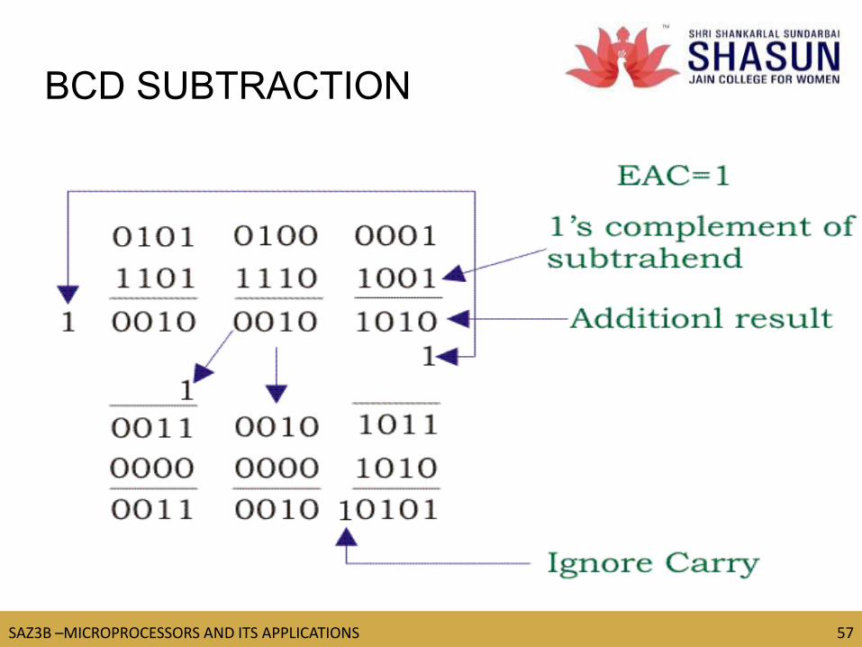
BCD SUBTRACTION

TM
SAZ3B –MICROPROCESSORS AND ITS APPLICATIONS 58
58
BCD MULTIPLICATION

TM
SAZ3B –MICROPROCESSORS AND ITS APPLICATIONS 59
59
BCD DIVISION

TM
SAZ3B –MICROPROCESSORS AND ITS APPLICATIONS 60
60
MULTIBYTE ADDITION

TM
SAZ3B –MICROPROCESSORS AND ITS APPLICATIONS 61
61
UNIT-V
Interrupt
Implementing Interrupts
Multiple Interrupt 8085
Trap Problems
Problems on Implementing 8085 Interrupt
DMA Memory interfaces
RAM and ROM
I/O Interface
Direct I/O Memory mapped I/O
TM
SAZ3B –MICROPROCESSORS AND ITS APPLICATIONS 62
62
INTERRUPTS
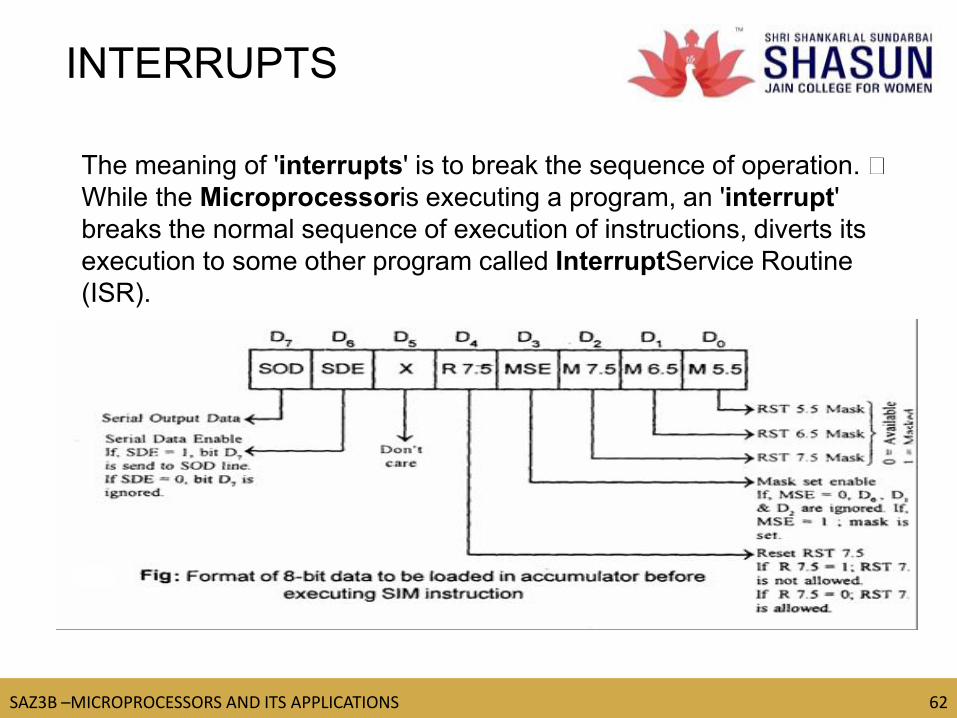
The meaning of 'interrupts' is to break the sequence of operation.
While the Microprocessoris executing a program, an 'interrupt'
breaks the normal sequence of execution of instructions, diverts its
execution to some other program called InterruptService Routine
(ISR).
TM
SAZ3B –MICROPROCESSORS AND ITS APPLICATIONS 63
63
https://www.youtube.com/watch?v=M5HgslgE1tE
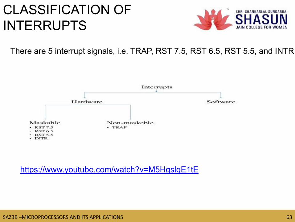
There are 5 interrupt signals, i.e. TRAP, RST 7.5, RST 6.5, RST 5.5, and INTR.
CLASSIFICATION OF
INTERRUPTS
TM
SAZ3B –MICROPROCESSORS AND ITS APPLICATIONS 64
64
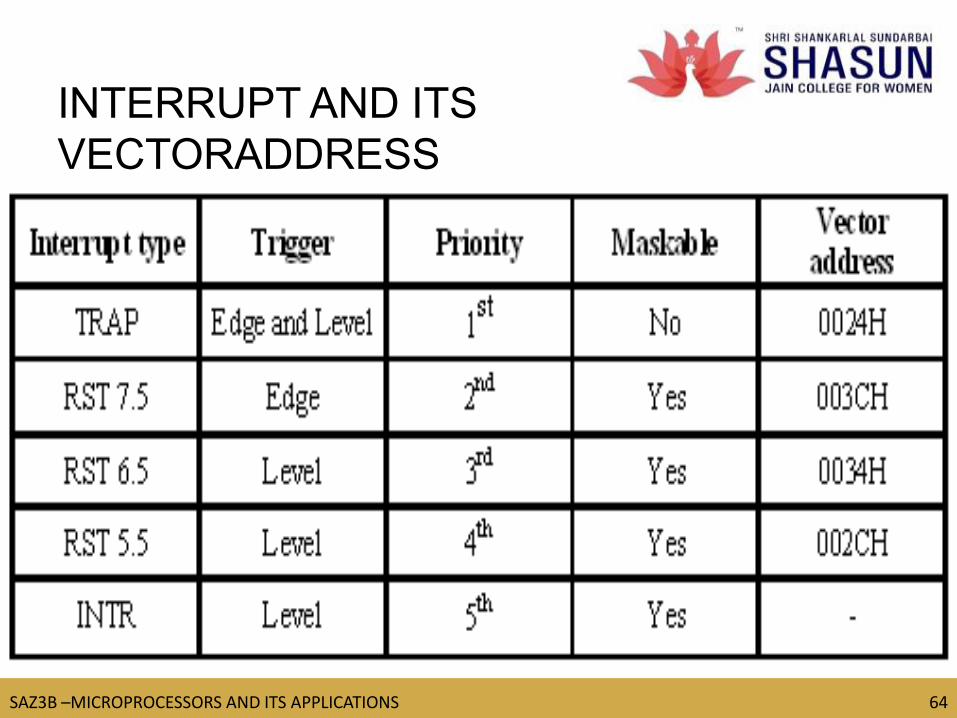
INTERRUPT AND ITS
VECTORADDRESS

TM
SAZ3B –MICROPROCESSORS AND ITS APPLICATIONS 65
65 https://www.youtube.com/watch?v=i2AeDvpj0CM
REPRESENTATION OF
MASKABLEAND NON
MASKABLE INTERRUPTS
Maskable interrupt − In this type of interrupt, we can disable the interrupt by writing some instructions into the program. For
example:RST7.5, RST6.5, RST5.5.
Non-Maskable interrupt − In this type of interrupt, we cannot disable the interrupt by writing some instructions into the program. For
example: TRAP.
TM
SAZ3B –MICROPROCESSORS AND ITS APPLICATIONS 66
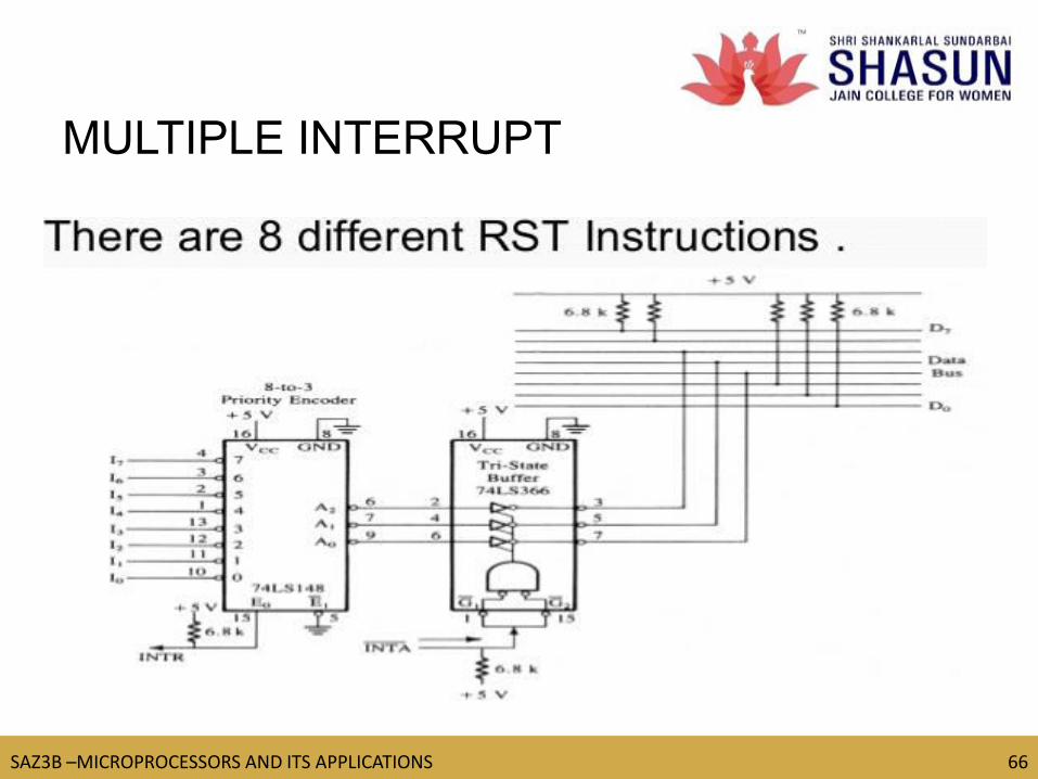
66
MULTIPLE INTERRUPT

TM
SAZ3B –MICROPROCESSORS AND ITS APPLICATIONS 67
67
8085 INTERRUPTS

TM
SAZ3B –MICROPROCESSORS AND ITS APPLICATIONS 68
68
8085 INTERRUPT
TM
SAZ3B –MICROPROCESSORS AND ITS APPLICATIONS 69
69
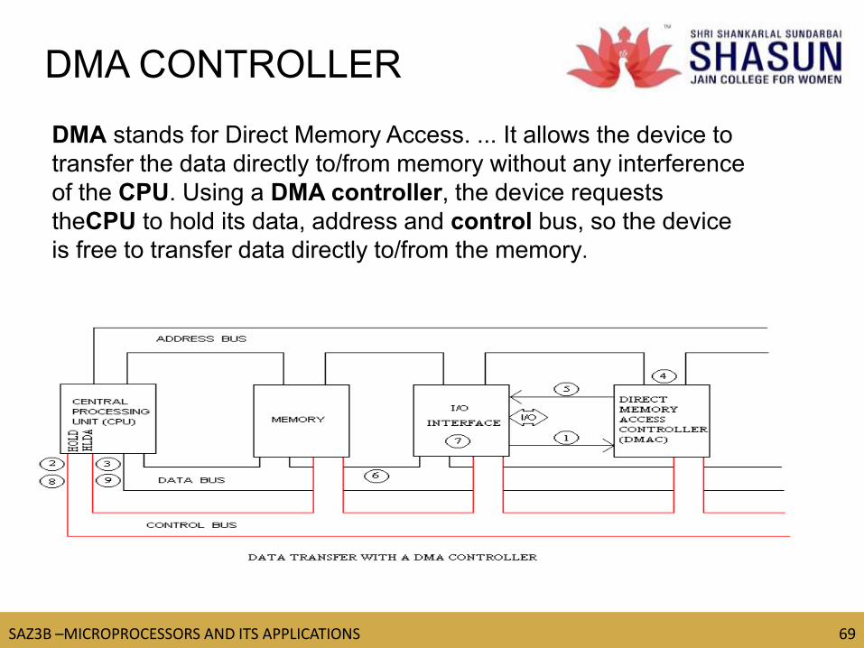
DMA CONTROLLER
DMA stands for Direct Memory Access. ... It allows the device to
transfer the data directly to/from memory without any interference
of the CPU. Using a DMA controller, the device requests
theCPU to hold its data, address and control bus, so the device
is free to transfer data directly to/from the memory.
TM
SAZ3B –MICROPROCESSORS AND ITS APPLICATIONS 70
70
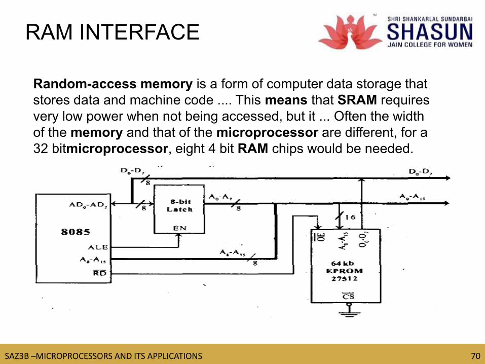
RAM INTERFACE
Random-access memory is a form of computer data storage that
stores data and machine code .... This means that SRAM requires
very low power when not being accessed, but it ... Often the width
of the memory and that of the microprocessor are different, for a
32 bitmicroprocessor, eight 4 bit RAM chips would be needed.

TM
SAZ3B –MICROPROCESSORS AND ITS APPLICATIONS 71
71
IO INTERFACE
There are various communication devices like the keyboard, mouse,
printer, etc. So, we need to interface the keyboard and other devices
with the microprocessor by using latches and buffers. This type of
interfacing is known as I/O interfacing.

TM
SAZ3B –MICROPROCESSORS AND ITS APPLICATIONS 72
72
DIRECT I/O MEMORY

TM
SAZ3B –MICROPROCESSORS AND ITS APPLICATIONS 73
73
D/F BETWEEN MEMORY
MAPPED I/O AND I/O MAPPED I/O
TM
SAZ3B –MICROPROCESSORS AND ITS APPLICATIONS 74
74
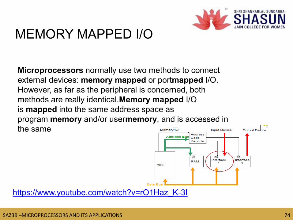
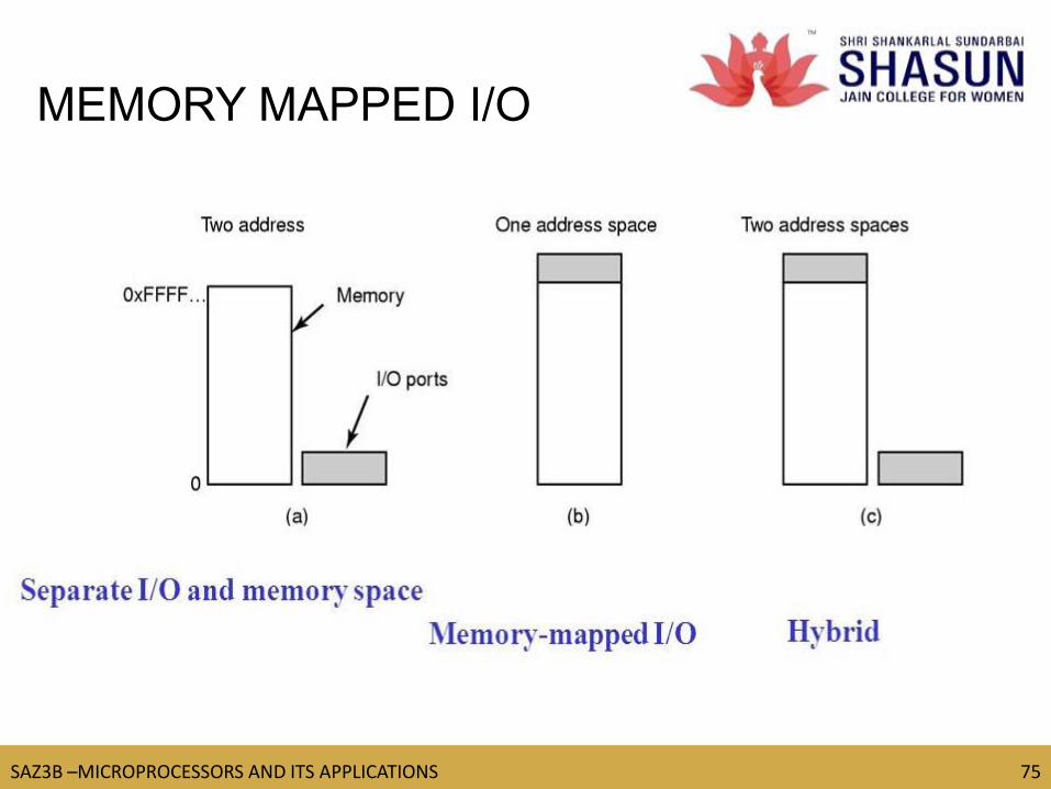
MEMORY MAPPED I/O
https://www.youtube.com/watch?v=rO1Haz_K-3I
Microprocessors normally use two methods to connect
external devices: memory mapped or portmapped I/O.
However, as far as the peripheral is concerned, both
methods are really identical.Memory mapped I/O
is mapped into the same address space as
program memory and/or usermemory, and is accessed in
the same
TM
SAZ3B –MICROPROCESSORS AND ITS APPLICATIONS 75
75
MEMORY MAPPED I/O