sawstopsawstop® owner’s manual contractor saw mobile base model mb-cns-000 l r r aise never place...
TRANSCRIPT
SawStop ®
OWNER’S MANUAL
Contractor Saw Mobile Base
Model MB-CNS-000
Lower
RaiseNever place fingers, toes or other body parts
under the mobile base.
! WARNING
1. Never place fingers, toes or other
body parts under the mobile base.
2. Always use the saw and the mobile
base on a level surface. 3. Lower the saw before using
saw when it is raised off
4. Lower the saw slo
drop back to.
! WARNING
1 SawStop Contractor Mobile Base
Unpacking Your Mobile Base
Safety
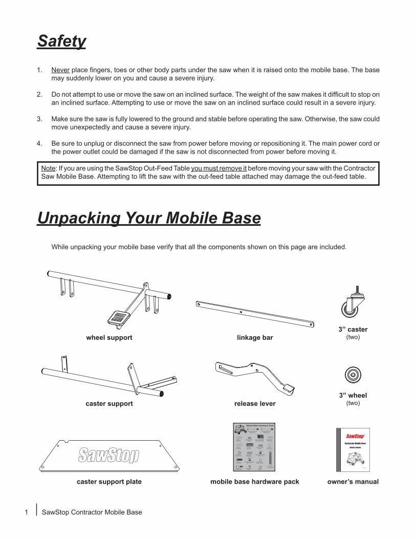
While unpacking your mobile base verify that all the components shown on this page are included.
release lever
3” caster(two)
3” wheel(two)
caster support plate
linkage bar
caster support
wheel support
mobile base hardware pack owner’s manual
SawStopSawStop ®
OWNER’S MANUAL
Contractor Mobile Base
Lower
Raise Never place fingers, toes or other body partsunder the mobile base.
! WARNING
1. Never placefingers, toes or other
body parts under the mobile base.
2. Always use the saw and the mobile
base on a level surface. 3. Lower the saw before us
saw when it is raised off
4. Lower the saw sl
drop back to.
! WARNING
Model MB-CNS-000
Mobile Base Hardware Pack
Nylon Hex Nuts, M6 (2) 4
Lock Washers, M8 x 13.6 (4) 6
Flange Lock Nuts,M6 (2) 9
Shoulder Socket Screw, M8 x 17.7 (1) 15
Shoulder Socket Screw, M8 x 15.7 (1) 13
Nylon Hex Nut, M8 (1) 19
Cap Nut, M8 (1) 20
Extension Spring,(1)
17
Hex Bolts, M8 x 40 (2) 8
Caster Nuts, 3/8” thread (2) 12
Wave Washer, M10.5 x 14.5 (1) 16
Short Fixed Wheel Axle, M6 x 67.6 (1) 1
Long Fixed Wheel Axle, M6 x 73.8 (1) 2
Washers, M6 x 16 (4) 3
Button Head Socket Screws, M8 x 20 (4) 5
Washers, M8 x 18 (4) 7
Hex Screw, M8 x 30 (1) 14
Release Lever Locking Screw (1) 18
Lock Washers, M10.5 x 17 (2) 11
Washers, M10.5 x 25 (2) 10
Lower
Raise Never place fingers,toes or other body partsunder themobile base.
! WARNING
1. Never place fingers, toes or other
body parts under the mobile base.
2. Always use the saw and the mobile
baseon a level surface. 3. Lower the sawbefore using
saw when it is raised off
4.Lower thesaw slo drop back to.
! WARNING
1. Never place fingers, toes or other body parts under the saw when it is raised onto the mobile base. The base may suddenly lower on you and cause a severe injury.
2. Do not attempt to use or move the saw on an inclined surface. The weight of the saw makes it difficult to stop on an inclined surface. Attempting to use or move the saw on an inclined surface could result in a severe injury.
3. Make sure the saw is fully lowered to the ground and stable before operating the saw. Otherwise, the saw could move unexpectedly and cause a severe injury.
4. Be sure to unplug or disconnect the saw from power before moving or repositioning it. The main power cord or the power outlet could be damaged if the saw is not disconnected from power before moving it.
Note: If you are using the SawStop Out-Feed Table you must remove it before moving your saw with the Contractor Saw Mobile Base. Attempting to lift the saw with the out-feed table attached may damage the out-feed table.

SawStop Contractor Mobile Base 2
Installing Your Mobile Base
Mobile Base Hardware Pack
Nylon Hex Nuts, M6 (2) 4
Lock Washers, M8 x 13.6 (4) 6
Flange Lock Nuts,M6 (2) 9
Shoulder Socket Screw, M8 x 17.7 (1) 15
Shoulder Socket Screw, M8 x 15.7 (1) 13
Nylon Hex Nut, M8 (1) 19
Cap Nut, M8 (1) 20
Extension Spring,(1)
17
Hex Bolts, M8 x 40 (2) 8
Caster Nuts, 3/8” thread (2) 12
Wave Washer, M10.5 x 14.5 (1) 16
Short Fixed Wheel Axle, M6 x 67.6 (1) 1
Long Fixed Wheel Axle, M6 x 73.8 (1) 2
Washers, M6 x 16 (4) 3
Button Head Socket Screws, M8 x 20 (4) 5
Washers, M8 x 18 (4) 7
Hex Screw, M8 x 30 (1) 14
Release Lever Locking Screw (1) 18
Lock Washers, M10.5 x 17 (2) 11
Washers, M10.5 x 25 (2) 10
Lower
RaiseNever place fingers,toes or other body parts
under the mobile base.
! WARNING
1. Never place fingers, toes or other
body parts under the mobile base.
2. Always use the saw and the mobile
base on a level surface. 3. Lower the saw before using
saw when it is raised off
4. Lower the saw slo
drop back to.
! WARNING
14
3
Installing Your Mobile Base
Fig. 1
Fig. 2
Fig. 3
1. Locate all of the mobile base components shown on page 1. All of the hardware needed to install the mobile base is located on the mobile base hardware pack (see Fig. 1). In order to easily identify the hardware used in each of the following steps, the different pieces of hardware are numbered on the hardware pack and in the figures. If you are missing the hardware pack or any of the other mobile base components, call the SawStop Service Department at 503-582-9934 for replacements.
You will need the following tools to complete the mobile base installation: • two 10 mm wrenches • two 13 mm wrench • a 14 mm wrench • a 5 mm hex key
Note: The stand for your contractor saw must be fully assembled before installing the mobile base.
2. Take the wheel support and mount one of the 3 inch wheels to the end furthest from the foot pedal. Use the short axle, one M6 washer, and one M6 nylon hex nut to mount the wheel to the support as shown in Fig. 2. Fully tighten the nut using a 10 mm wrench and a 5 mm hex key.
3. Mount the other 3 inch wheel to the other end of the wheel support. Use the long axle, one M6 washer, and one M6 nylon hex nut to mount the wheel to the support as shown in Fig. 3. Do not tighten the nut because it will be removed in a later installation step.
2
4 3
foot pedal3 inch wheel
3 inch wheel
foot pedal
9
9
3
8
3
8
Installing Your Mobile Base
56 7
567
Installing Your Mobile Base
Fig. 4a
Fig. 5
3 SawStop Contractor Mobile Base
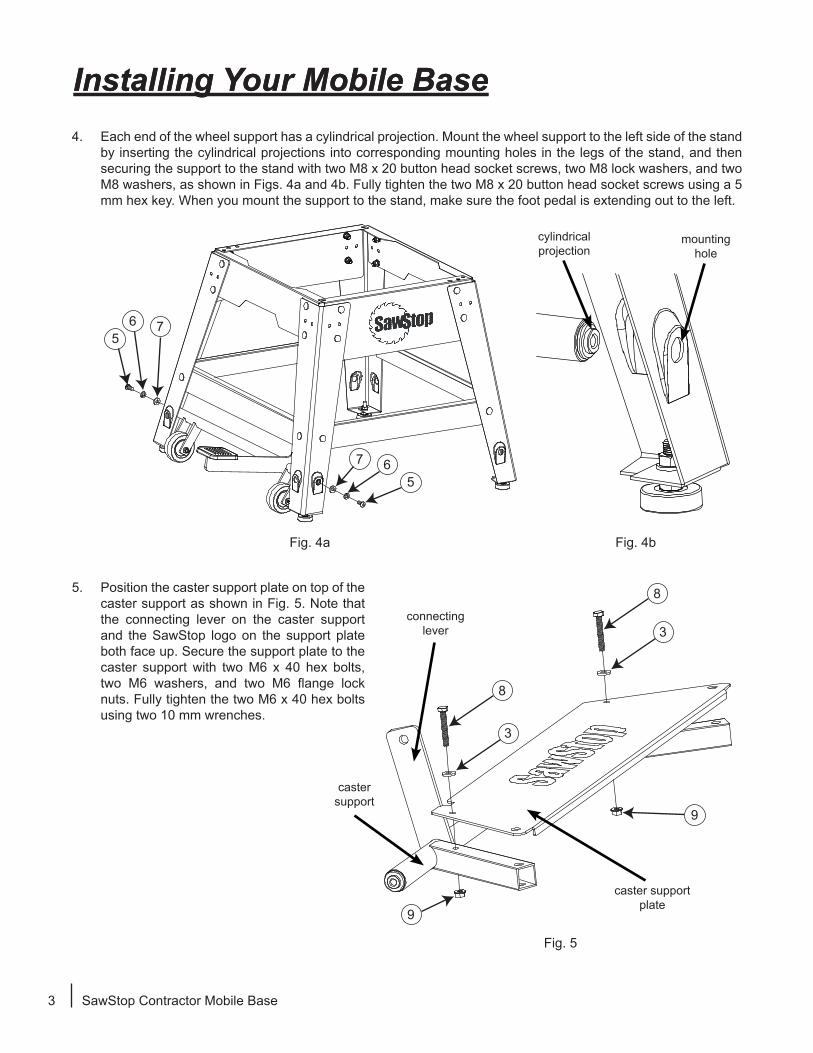
4. Each end of the wheel support has a cylindrical projection. Mount the wheel support to the left side of the stand by inserting the cylindrical projections into corresponding mounting holes in the legs of the stand, and then securing the support to the stand with two M8 x 20 button head socket screws, two M8 lock washers, and two M8 washers, as shown in Figs. 4a and 4b. Fully tighten the two M8 x 20 button head socket screws using a 5 mm hex key. When you mount the support to the stand, make sure the foot pedal is extending out to the left.
5. Position the caster support plate on top of the caster support as shown in Fig. 5. Note that the connecting lever on the caster support and the SawStop logo on the support plate both face up. Secure the support plate to the caster support with two M6 x 40 hex bolts, two M6 washers, and two M6 flange lock nuts. Fully tighten the two M6 x 40 hex bolts using two 10 mm wrenches.
connecting lever
caster support plate
caster support
Fig. 4b
cylindrical projection
mountinghole

Installing Your Mobile Base
56
7
56 7
Fig. 6a
Fig. 7
Fig. 6b
SawStop Contractor Mobile Base 4
6. The caster support must be positioned inside the stand. If your contractor saw is not yet on the stand, then lift the right side of the stand a few inches off the floor and slide the caster support into position between the two right legs, as shown in Fig. 6a. Make sure that the SawStop logo on the support plate is facing up and that the connecting lever is on the inside of the stand. If your contractor saw is already mounted to the stand, you can remove the lower bracket on the right side of the stand and angle the caster support into place as shown in Fig. 6b. Once the caster support is in place, reinstall the bracket that you removed.
7. Each end of the caster support has a cylindrical projection. Mount the caster support to the right side of the stand by inserting the cylindrical projections into corresponding mounting holes in the legs of the stand, and then securing the support to the stand with two M8 x 20 button head socket screws, two M8 lock washers, and two M8 washers, as shown in Fig. 7. Fully tighten the two M8 x 20 button head socket screws using a 5 mm hex key. Make sure that the SawStop logo on the support plate is facing up and that the connecting lever is on the inside of the stand.
lift up the stand and slide the caster support into place
remove the lower bracket on the right side
and angle the caster support into place
Installing Your Mobile Base
11
10
12
34
13
Fig. 8
Fig. 9
Fig. 10
5 SawStop Contractor Mobile Base
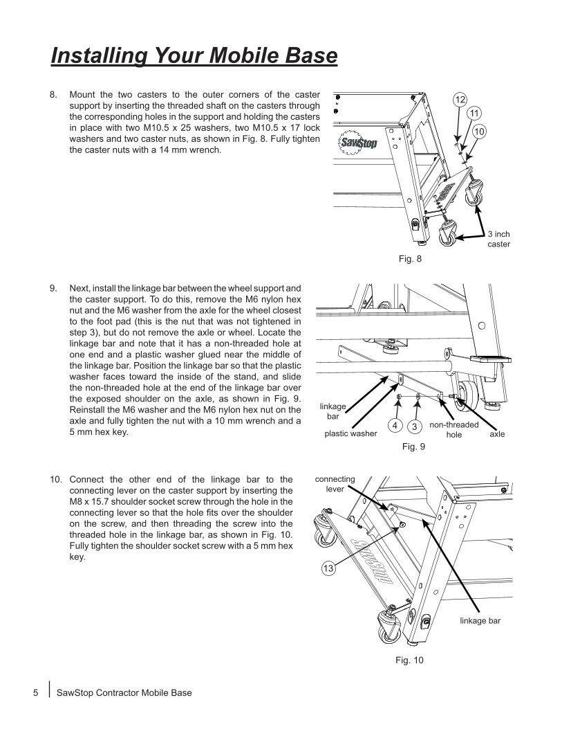
8. Mount the two casters to the outer corners of the caster support by inserting the threaded shaft on the casters through the corresponding holes in the support and holding the casters in place with two M10.5 x 25 washers, two M10.5 x 17 lock washers and two caster nuts, as shown in Fig. 8. Fully tighten the caster nuts with a 14 mm wrench.
9. Next, install the linkage bar between the wheel support and the caster support. To do this, remove the M6 nylon hex nut and the M6 washer from the axle for the wheel closest to the foot pad (this is the nut that was not tightened in step 3), but do not remove the axle or wheel. Locate the linkage bar and note that it has a non-threaded hole at one end and a plastic washer glued near the middle of the linkage bar. Position the linkage bar so that the plastic washer faces toward the inside of the stand, and slide the non-threaded hole at the end of the linkage bar over the exposed shoulder on the axle, as shown in Fig. 9. Reinstall the M6 washer and the M6 nylon hex nut on the axle and fully tighten the nut with a 10 mm wrench and a 5 mm hex key.
10. Connect the other end of the linkage bar to the connecting lever on the caster support by inserting the M8 x 15.7 shoulder socket screw through the hole in the connecting lever so that the hole fits over the shoulder on the screw, and then threading the screw into the threaded hole in the linkage bar, as shown in Fig. 10. Fully tighten the shoulder socket screw with a 5 mm hex key.
linkage bar
linkage bar
connecting lever
plastic washer axlenon-threaded
hole
3 inch caster
Installing Your Mobile Base
15 16
1817
14
Fig. 11
Fig. 12
Fig. 13
SawStop Contractor Mobile Base 6
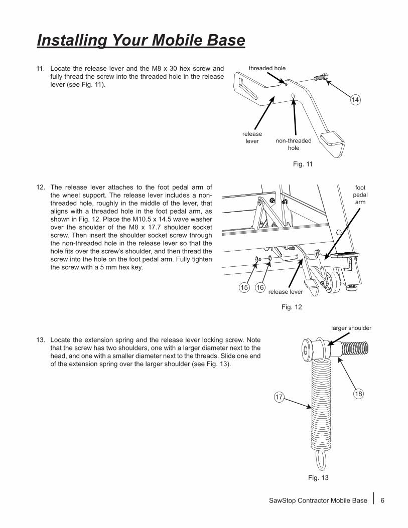
11. Locate the release lever and the M8 x 30 hex screw and fully thread the screw into the threaded hole in the release lever (see Fig. 11).
release lever
12. The release lever attaches to the foot pedal arm of the wheel support. The release lever includes a non-threaded hole, roughly in the middle of the lever, that aligns with a threaded hole in the foot pedal arm, as shown in Fig. 12. Place the M10.5 x 14.5 wave washer over the shoulder of the M8 x 17.7 shoulder socket screw. Then insert the shoulder socket screw through the non-threaded hole in the release lever so that the hole fits over the screw’s shoulder, and then thread the screw into the hole on the foot pedal arm. Fully tighten the screw with a 5 mm hex key.
release lever
foot pedal arm
13. Locate the extension spring and the release lever locking screw. Note that the screw has two shoulders, one with a larger diameter next to the head, and one with a smaller diameter next to the threads. Slide one end of the extension spring over the larger shoulder (see Fig. 13).
larger shoulder
threaded hole
non-threaded hole

Installing Your Mobile Base
19
20
Fig. 16
Fig. 15
Fig. 14
7 SawStop Contractor Mobile Base
Congratulations, your mobile base is now installed.
14. The end of the release lever opposite the foot pedal includes a slot. Pivot the release lever until the slot aligns with the plastic washer and threaded hole in the middle of the linkage bar. Insert the release lever locking screw through the slot in the release lever and thread it into the hole in the linkage bar, making sure to keep the extension spring on the screw (see Fig. 14). Fully tighten the release lever locking screw with a 5 mm hex key.
15. Locate the M8 nylon hex nut and thread it onto the release lever locking screw to hold the screw in place as shown in Fig. 15. Fully tighten the nut with a 13 mm wrench.
16. Stretch the free end of the extension spring over the end of the M8 x 30 hex screw that extends from the release lever. Thread the M8 cap nut onto the M8 x 30 hex screw to hold the extension spring in place (see Fig. 16) , and fully tighten the cap nut with two 13 mm wrenches.
release lever slot

SawStop Contractor Mobile Base 8
Using Your Mobile Base1. To move your saw with the mobile base, step down on the foot pedal to raise the saw off the floor and onto
the wheels (see Fig. 17). Step on the foot pedal until the release lever locking screw slides into the locked position in the release lever. Make sure that your foot does not come into contact with the release lever while you are stepping on the foot pedal to raise the saw, otherwise the mobile base will not stay in the raised position.
2. Push the saw to its desired location. The mobile base has two wheels on the left side and two casters on the right side, and therefore it may be easier to maneuver the saw by pushing from the right side.
3. To unlock the release lever and lower the saw back to the floor, step down on the foot pedal and the release lever simultaneously (see Fig. 18). Slowly lift your foot upwards to allow the saw to gently lower to the floor. Do not step on the release lever without having your foot on the foot pedal or your saw will lower to the floor rapidly.
Fig. 17
Fig. 18
foot pedal -step here to raise
simultaneously step on the foot pedal and the release lever
to lower the saw
release lever locking screw
locked position in the release lever
release lever
Note: The SawStop Contractor Mobile Base has been engineered to lift saws with or without extension tables. You do not need an additional arm extending out from the mobile base to support your extension table.
However, if you have a SawStop 30” Out-Feed Table attached you must remove it before using the mobile base to move your saw.
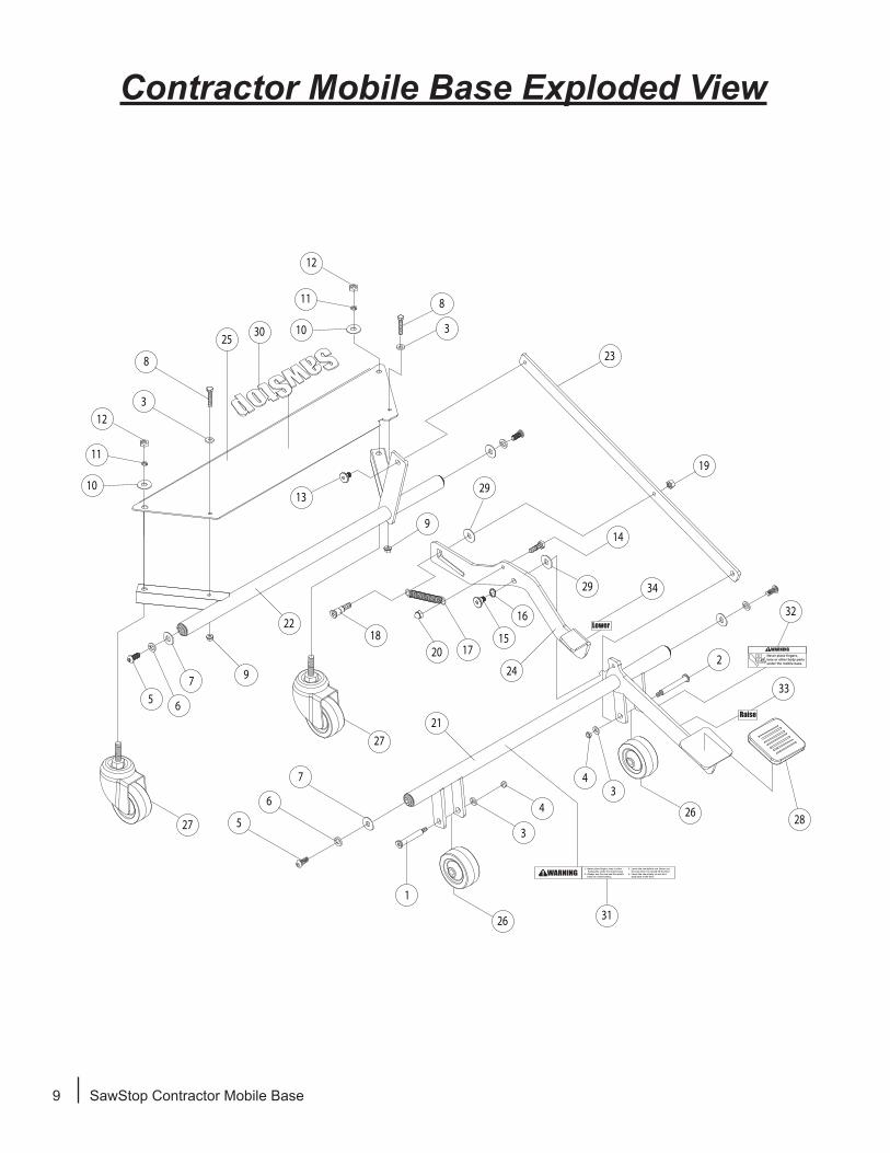
Contractor Mobile Base Exploded View
1
1. Never place fingers, toes or other body parts under the mobile base.2. Always use the saw and the mobile base on a level surface.
Never place fingers, toes or other body parts under the mobile base.
3. Lower the saw before use. Never use the saw when it is raised off the floor. 4. Lower the saw slowly, do not let it drop back to the floor.
! WARNING
! WARNING
Raise
Lower
2
3
3
3
3
4
4
5
5 6
6
7
7
8
8
9
9
10
11
13
14
1517
18
19
20
21
22
23
24
25
26
26
27
27 28
29
29
30
31
32
33
34
12
10
11
12
16
9 SawStop Contractor Mobile Base

Contractor Mobile Base Parts List
SawStop Contractor Mobile Base 10
No. Description Part No. Qty.Complete Mobile Base Assembly MB-CNS-000 1
1 Short Axle M6x67.6 MB-CNS-001 12 Long Axle M6x73.8 MB-CNS-002 13 M6x16x1.5 Washer MB-CNS-003 44 M6 Nylon Hex Nut MB-CNS-004 25 M8x20 Button Head Socket Screw MB-CNS-005 46 M8x13.6 Lock Washer MB-CNS-006 47 M8x18x1.5 Washer MB-CNS-007 48 M6x40 Hex Bolt MB-CNS-008 29 M6 Flange Lock Nut MB-CNS-009 2
10 M10.5x25 Washer MB-CNS-010 211 M10.5x17 Lock Washer MB-CNS-011 212 Caster Nut (3/8” thread) MB-CNS-012 213 M8x1.25x15.7 Shoulder Socket Screw MB-CNS-013 114 M8x30 Hex Screw MB-CNS-014 115 M8x1.25x17.7 Shoulder Socket Screw MB-CNS-015 116 M10.5x14.5 Wave Washer MB-CNS-016 117 Extension Spring MB-CNS-017 118 Release Lever Locking Screw MB-CNS-018 119 M8 Nylon Hex Nut MB-CNS-019 120 M8 Cap Nut MB-CNS-020 121 Wheel Support MB-CNS-021 122 Caster Support MB-CNS-022 123 Linkage Bar MB-CNS-023 124 Release Lever MB-CNS-024 125 Caster Support Plate MB-CNS-025 126 3” Wheel MB-CNS-026 227 3” Caster MB-CNS-027 228 Foot Pad MB-CNS-028 129 Plastic Spacer (Adhesive Backed) MB-CNS-029 230 SawStop Logo Label MB-CNS-030 131 Main Warning Label MB-CNS-031 132 Finger/Toe Warning Label MB-CNS-032 133 Raise Label MB-CNS-033 134 Lower Label MB-CNS-034 1N/A Owner’s Manual MB-CNS-035 1N/A Hardware Pack MB-CNS-036 1
October 2017
© SawStop, LLCAll Rights Reserved.
Updates of this manual may be available at www.sawstop.com.
SawStop, LLC9564 S.W. Tualatin RoadTualatin, Oregon 97062
www.sawstop.com
Main Phone - (503) 570-3200Service - (503) 582-9934
Fax - (503) 570-3303Email: [email protected]
WarrantySawStop warrants to the original retail purchaser of the Contractor Saw Mobile Base accompanying
this manual that the mobile base will be free from defects in material and workmanship for ONE YEAR from the date of purchase. This warranty does not apply to defects arising from misuse, abuse, negligence, accidents, normal wear-and-tear, unauthorized repair or alteration, or lack of maintenance.
Please contact SawStop to take advantage of this warranty. If SawStop determines the mobile base is defective in material or workmanship, and not due to misuse, abuse, negligence, accidents, normal wear-and-tear, unauthorized repair or alteration, or lack of maintenance, then SawStop will, upon proof of purchase and at its expense, send replacement parts to the original retail purchaser necessary to cure the defect. Alternatively, SawStop will repair the mobile base, provided it is returned to SawStop, shipping prepaid, within the warranty period.
SawStop disclaims any and all other express or implied warranties, including merchantability and fitness for a particular purpose. SawStop shall not be liable for death, injuries to persons or property, or incidental, consequential, contingent or special damages arising from the use of the mobile base.
This warranty gives you specific legal rights. You may have other rights which vary from state to state.